
Issue 2
Date of issue:
3rd May 2005
Techne is a trademark.
© Techne, 2003
Tecal 140F, Tecal 425F
and Tecal 650F Calibrators
Operator's Manual


PAGE 1
T e c a l 1 4 0 F, T e c a l 4 2 5 F a n d T e c a l 6 5 0 F O P E R A T O R ’ S M A N U A L
CONTENTS
Tecal Calibrator Operator’s Manual
page
SAFETY AND INSTALLATION
English 4
Français 5
Deutsch 6
Español 7
THE CALIBRATOR 8
Applications 8
Warning 8
Working Conditions 9
Packing 9
Installation 9
Specification Tecal 140F 10
Specification Tecal 425F 11
Specification Tecal 650F 12
WHEN YOU SWITCH ON 13
Front Panel controls 13
Setting the Units for Temperature 13
Setting the Operating Temperature 15
After Use 15
Overtemperaturecut-out 15
RS232 SERIAL INTERFACE (where applicable) 16
Sending data to the PC (Auto Control) 16
TECHNICAL INFORMATION 17
General advice 17
General Fault finding 17
Replacement parts 18
Accessories 18
Inserts Tecal 140F and Tecal 425F 18
Inserts Tecal 650F 19

PAGE 2
T e c a l 1 4 0 F, T e c a l 4 2 5 F a n d T e c a l 6 5 0 F O P E R A T O R ’ S M A N U A L

PAGE 3
T e c a l 1 4 0 F, T e c a l 4 2 5 F a n d T e c a l 6 5 0 F O P E R A T O R ’ S M A N U A L
NOTES

PAGE 4
T e c a l 1 4 0 F, T e c a l 4 2 5 F a n d T e c a l 6 5 0 F O P E R A T O R ’ S M A N U A L
Introduction
Please read all the information in this booklet before using
the unit.
Warning
HIGH TEMPERATURES ARE DANGEROUS: they can
cause serious burns to operators and ignite combustible
material.
Techne have taken great care in the design of these units
to protect operators from hazards, but users should pay
attention to the following points:
• USE CARE AND WEAR PROTECTIVE GLOVES TO
PROTECT HANDS;
• DO NOT put hot objects on or near combustible
objects;
• DO NOT operate the unit close to inflammable liquids
or gases;
• DO NOT place any liquid directly in your unit;
• At all times USE COMMON SENSE.
Operator Safety
All users of Techne equipment must have available the
relevant literature needed to ensure their safety.
It is important that only suitably trained personnel operate
this equipment, in accordance with the instructions
contained in this manual and with general safety standards
and procedures. If the equipment is used in a manner not
specified by Techne the protection provided by the
equipment to the user may be impaired.
All Techne units have been designed to conform to
international safety requirements and are fitted with an
overtemperature cutout. On some models, the cutout is
adjustable and should be set to suit the application. On all
other models the cutout is preset to protect the unit.
If a safety problem should be encountered, switch off at the
mains socket and remove the plug from the supply.
Installation
1. All Techne units are supplied with a power cable. This
may be integral or plug-in.
2. Before connecting the mains supply, check the voltage
against the rating plate. Connect the mains cable to a
suitable plug according to the table below. Note that
the unit must be earthed to ensure proper electrical
safety.
Connections 220/240V 110/120V
Live Brown Black
Neutral Blue White
Earth Green/yellow Green
The fused plug supplied with the mains lead for use in
the UK is fitted with the following value fuse to protect
the cable:
230V UK 10 AMP
The fuse in the unit protects the unit and the operator.
Note that units marked 230V on the rating plate work
at 220V; units marked 120V work at 110V. In both
cases, however, the heating rate will degrade by
approximately 8%. The rating plate is on the rear of the
unit.
3. Plug the mains cable into the socket on the rear of the
unit.
4. Place the unit on a suitable bench or flat workspace, or
in a fume cupboard if required, ensuring that the air
inlet vents on the underside are free from obstruction.
5. Note that the following symbols may be next to the
indicator lamps on the front panel of the units and have
the following meanings:
: the power indicator
: the heater indicator
: the overtemperature indicator
6. Symbols on or near the power switch of the unit have
the following meanings:
I : mains switch On
O : mains switch Off
After use
When you have finished heating samples, remember that
parts of the unit – the tubes, blocks and associated
accessories – may be very hot. Take the precautions listed
earlier.
Guarantee
The unit is guaranteed against any defect in material or
workmanship for the period specified on the enclosed
guarantee card. This period is from the date of purchase,
and within this period all defective parts will be replaced
free of charge provided that the defect is not the result of
misuse, accident or negligence. Servicing under this
guarantee should be obtained from the supplier.
Notwithstanding the description and specification(s) of the
units contained in the Operator’s Manual, Techne hereby
reserves the right to make such changes as it sees fit to the
units or to any component of the units.
This Manual has been prepared solely for the convenience
of Techne customers and nothing in this Instruction Book
shall be taken as a warranty, condition or representation
concerning the description, merchantability, fitness for
purpose or otherwise of the units or components.
User maintenance
NOTE THAT THIS EQUIPMENT SHOULD ONLY BE
DISMANTLED BY PROPERLY TRAINED PERSONNEL.
REMOVING THE SIDE, FRONT OR REAR PANELS
EXPOSES POTENTIALLY LETHAL MAINS VOLTAGES.
THERE ARE NO USER MAINTAINABLE PARTS WITHIN
THE EQUIPMENT.
In the unlikely event that you experience any problems with
your unit which cannot easily be remedied, you should
contact your supplier and return the unit if necessary.
Please include any details of the fault observed and
remember to return the unit in its original packing. Techne
accept no responsibility for damage to units which are not
properly packed for shipping: if in doubt, contact your
supplier. See the Decontamination Certificate supplied
with your unit.
1. Cleaning
Before cleaning your unit ALWAYS disconnect from
the power supply and allow to cool below 50° C.
Your unit can be cleaned by wiping with a damp soapy
cloth. Care should be exercised to prevent water from
running inside the unit. Do not use abrasive cleaners.
2. Fuses
Your unit is protected by one or two fuses. These
should only be changed by suitably qualified personnel.
If the fuses blow persistently, a serious fault is indicated
and you may need to return the unit to your supplier for
repair.

PAGE 5
T e c a l 1 4 0 F, T e c a l 4 2 5 F a n d T e c a l 6 5 0 F O P E R A T O R ’ S M A N U A L
Introduction
Veuillez lire attentivement toutes les instructions de ce
document avant d’utiliser l’appareil.
Avertissement
DANGER DE TEMPERATURES ELEVEES : les opérateurs
peuvent subir de graves brûlures et les matériaux
combustibles risquent de prendre feu.
Techne a apporté un soin tout particulier à la conception de
ces appareils de façon à assurer une protection maximale
des opérateurs, mais il est recommandé aux utilisateurs
de porter une attention spéciale aux points suivants :
• PROCEDER AVEC SOIN ET PORTER DES GANTS
POUR SE PROTEGER LES MAINS.
• NE PAS poser d’objets chauds sur ou près de matériaux
combustibles.
• NE PAS utiliser l’appareil à proximité de liquides ou de
gaz inflammables.
• NE PAS verser de liquide directement dans l’appareil.
• FAIRE TOUJOURS PREUVE DE BON SENS.
Sécurité de l’opérateur
Tous les utilisateurs de produits Techne doivent avoir pris
connaissance des manuels et instructions nécessaires à
la garantie de leur sécurité.
Important : cet appareil doit impérativement être manipulé
par un personnel qualifié et utilisé selon les instructions
données dans ce document, en accord avec les normes et
procédures de sécurité générales. Dans le cas où cet
appareil ne serait pas utilisé selon les consignes précisées
par Techne, la protection pour l’utilisateur ne serait alors
plus garantie.
Tous les appareils Techne sont conçus pour répondre aux
normes de sécurité internationales et sont dotés d’un
coupe-circuit en cas d’excès de température. Sur certains
modèles, ce coupe-circuit est réglable pour s’adapter à
l’application désirée. Sur d’autres modèles, il est pré-
réglée en usine pour assurer la protection de l’appareil.
Dans le cas d’un problème de sécurité, coupez l’alimentation
électrique au niveau de la prise murale et enlevez la prise
connectée à l’appareil.
Installation
1. Tous les appareils Techne sont livrés avec un câble
d’alimentation qui peut être intégré à l’appareil ou à
raccorder.
2. Avant de brancher l’appareil, vérifiez la tension requise
indiquée sur la plaque d’identification. Raccordez le
câble électrique à la prise appropriée en vous reportant
au tableau ci-dessous. Il est important que l’appareil
soit relié à la terre pour assurer la protection
électrique requise.
Connexions 220/240 V 110/120 V
Phase Marron Noir
Neutre Blue Blanc
Terre Vert/juane Vert
Le fusible à l’intérieur de l’appareil est destiné à
assurer la protection de l’appareil et de l’opérateur.
Remarque : les appareils dont la plaque indique 230
V peuvent fonctionner sur 220 V, et ceux dont la plaque
indique 120 V peuvent fonctionner sur 110 V. Dans les
deux cas cependant, le capacité de chauffage diminuera
d’environ 8 %. La plaque d’identification se trouve à
l’arrière de l’appareil.
3. Raccordez le câble d’alimentation à la prise située à
l’arrière de l’appareil.
4. Placez l’appareil sur un plan de travail ou surface
plane, ou le cas échéant, dans une hotte d’aspiration,
en s’assurant que les trous d’aération situés sous
l’appareil ne sont pas obstrués.
5. Les symboles ci-dessous situés à côté des témoins
lumineux sur la face avant de l’appareil ont la
signification suivante :
: témoin d’alimentation
: témoin de chauffage
: témoin d’excès de température
6. Les symboles situés sur ou à côté de l’interrupteur de
l’appareil ont la signification suivante :
O : arrêt
I : marche
Après utilisation
Lorsque vous avez fini de chauffer les échantillons, n’oubliez
pas que certaines parties de l’appareil - les éprouvettes,
leurs supports et autres accessoires - risquent d’être très
chaudes. Il est donc recommandé de toujours prendre les
précautions citées plus haut.
Garantie
L’appareil est garanti contre tout défaut ou vice de fabrication
pour la durée figurant sur la carte de garantie, à compter de
la date d’achat de l’appareil. Au cours de cette période,
toutes les pièces défectueuses seront remplacées
gratuitement, dans la mesure où la défaillance n’est pas
due à une mauvaise utilisation, un accident ou une
négligence. Toute réparation sous garantie sera effectuée
par le fournisseur.
Malgré la description et les spécifications de l’appareil
données dans le manuel de l’utilisateur, Techne se réserve
le droit d’effectuer les changements nécessaires à l’appareil
ou à tout élément qui entre dans sa composition.
Ce manuel a été exclusivement rédigé à l’attention des
clients de Techne, et aucun élément de ce guide
d’instructions ne peut être utilisé comme garantie, condition
ou représentation concernant la description,
commercialisation, adaptation aux conditions d’utilisation
ou autre des appareils ou de leurs composants.
Entretien utilisateur
IMPORTANT : CET APPAREIL NE PEUT ETRE
DEMONTE QUE PAR DU PERSONNEL QUALIFIE.
LORSQUE LES PANNEAUX AVANT, ARRIERE ET
LATERAUX SONT DEMONTES, L’OPERATEUR EST
EXPOSE A DES TENSIONS QUI PEUVENT ETRE
MORTELLES.
CET APPAREIL NE CONTIENT AUCUN ELEMENT QUI
DEMANDE UN ENTRETIEN DE LA PART DE
L’UTILISATEUR.
Dans le cas peu probable où votre appareil présente un
défaut de fonctionnement auquel il est difficile de remédier,
il est alors préférable de contacter votre fournisseur et, le
cas échéant, de renvoyer le matériel. Veuillez inclure une
description détaillée du problème constaté et retourner
l’appareil dans son emballage d’origine. Techne ne sera
pas tenu responsable des dommages subis par tout appareil
dont l’emballage est inadéquat pour le transport. Pour plus
de sûreté, contactez votre fournisseur. Voir le certificat de
décontamination livré avec le produit.
1. Nettoyage
Avant de nettoyer l’appareil, assurez-vous TOUJOURS
que le câble d’alimentation est déconnecté et laissez
la température redescendre en dessous de 50 °C.
Utilisez un chiffon imprégné d’eau savonneuse pour
nettoyer l’appareil. Veillez à ne pas introduire d’eau
dans l’appareil. N’utilisez pas de produits abrasifs.
2. Fusibles
La protection de l’appareil est assurée par un ou deux
fusibles dont le remplacement ne peut être effectué
que par un personnel qualifié.
Si les fusibles sautent sans arrêt, il s’agit d’un problème
sérieux. Nous vous conseillons dans ce cas de prendre
contact avec votre fournisseur pour réparation.

PAGE 6
T e c a l 1 4 0 F, T e c a l 4 2 5 F a n d T e c a l 6 5 0 F O P E R A T O R ’ S M A N U A L
Nach dem Gebrauch
Vergessen Sie nicht, daß Teile des Gerätes (die Gefäße,
die Blöcke und andere Zubehörteile) nach dem Erhitzen
von Proben noch sehr heiß sein können. Bitte beachten
Sie die oben genannten Vorsichtsmaßnahmen.
Garantie
Die Garantiedauer des Gerätes ist auf der beiliegenden
Garantiekarte angegeben und schließt Fehler im Material
oder der Verarbeitung ein. Die Garantiedauer beginnt am
Tag des Einkaufs. Sämtliche defekte Teile werden innerhalb
dieses Zeitraumes kostenlos ersetzt unter der
Voraussetzung, daß dem Defekt keine unsachgemäße
Handhabung, Fahrlässigkeit oder ein Unfall zugrundeliegt.
Der unter diese Garantie fallende Service wird vom
Lieferanten geleistet.
Ungeachtet der in dieser Gebrauchsanweisung enthaltenen
Beschreibungen und Spezifikationen, behält sich Techne
hiermit das Recht vor, Änderungen an den Geräten bzw.
an einzelnen Geräteteilen durchzuführen.
Diese Gebrauchsanleitung wurde ausschließlich dazu
erstellt, um Kunden die Handhabung der Techne-Geräte
zu erleichtern. Nichts in dieser Gebrauchsanleitung darf
als Garantie, Bedingung oder Voraussetzung verstanden
werden, sei es die Beschreibung, Marktgängigkeit,
Zweckdienlichkeit oder sonstiges bezüglich der Geräte
oder deren Bestandteile.
Wartung durch den Bediener
BEACHTEN SIE, DASS DIESES GERÄT NUR VON
TECHNISCHEN FACHKRÄFTEN GEÖFFNET UND
DEMONTIERT WERDEN DARF.
DURCH ENTFERNEN DES GEHÄUSES ODER
GEHÄUSETEILEN SIND BAUTEILE MIT
LEBENGEFÄHRLICHEN SPANNUNGEN FREI
ZUGÄNGLICH.
IM INNERN DES GERÄTES BEFINDEN SICH KEINE
TEILE, DIE VOM ANWENDER GEWARTET WERDEN
MÜSSEN.
Falls Ihr Gerät nicht ordnungsgemäß arbeitet, wenden Sie
sich an Ihren Lieferanten oder senden Sie das Gerät wenn
nötig zurück. Fügen Sie eine genaue Beschreibung des
Defektes bei. Verpacken Sie das Gerät möglichst im
Originalkarton. Bitte beachten Sie, daß Techne und thermo-
DUX keine Haftung bei Transportschäden aufgrund
unzureichender Verpackung übernnehmen. Setzen Sie
sich im Zweifelsfall mit Ihrem Lieferanten in Verbindung.
Bitte beachten Sie die Entgiftungsbescheinigung, die Sie
mit dem Gerät erhalten haben.
1. Reinigen
Bevor Sie Ihr Gerät reinigen, sollten Sie
•zuerst den Netzstecker ziehen
•das Gerät unter 50°C abkühlen lassen.
Ein feuchtes Tuch mit Seifenlösung reinigt Ihr Gerät
am besten. Achten Sie darauf, daß kein Wasser in das
Gerät gelangt. Verwenden Sie keine Scheuermittel.
2. Sicherungen
Die Stromzuleitung ist durch ein oder zwei Sicherungen
geschützt. Diese sollten nur durch qualifiziertes
Fachpersonal ausgetauscht werden. Wenn die
Sicherung wiederholt durchbrennt, liegt ein größerer
Defekt vor. Das Gerät muß zur Reparatur an Ihren
Lieferanten eingesandt werden.
Einleitung
Bitte lesen Sie diese Bedienungsanleitung komplett bevor
Sie dieses Gerät benutzen.
Warnung
HOHE TEMPERATUREN SIND GEFÄHRLICH: sie können
dem Bediener ernsthafte Verletzungen zufügen und
brennbare Materialien können sich leicht entzünden.
Techne hat bei der Konstruktion dieses Gerätes sehr
darauf geachtet, daß der Bediener vor Gefahren geschützt
ist. Dennoch sollten Sie auf die folgenden Punkte achten:
· SEIEN SIE VORSICHTIG UND TRAGEN SIE
SCHUTZHANDSCHUHE
· Legen Sie heiße Gegenstände NICHT auf oder in die
Nähe von leicht brennbaren Materialien; vermeiden
Sie Arbeiten in der Nähe von leicht entzündbaren
Flüssigkeiten oder Gasen.
· Bringen sie KEINE Flüssigkeiten direkt in Ihr Gerät.
· Benutzen Sie immer den normalen Menschenverstand
Sicherheit des Anwenders
Alle Benutzer von Techne Geräten müssen Zugang zu der
entsprechenden Literatur haben, um ihre Sicherheit zu
gewähren.
Es ist wichtig, daß diese Geräte nur von entsprechend
geschultem Personal betrieben werden, das die in dieser
Gebrauchsanweisung enthaltenen Maßnahmen und
allgemeine Sicherheitsbestimmungen und -vorkehrungen
beachtet. Wenn das Gerät anders eingesetzt wird als vom
Hersteller empfohlen, kann dies die persönliche Sicherheit
des Anwenders beeinträchtigen. Die Geräte von Techne
entsprechen den internationalen Sicherheitsbestimmungen
und sind mit einem automatischen
Übertemperaturabschalter ausgestattet. Bei einigen
Modellen ist der Übertemperaturabschalter verstellbar und
sollte je nach Anwendung entsprechend eingestellt werden.
Bei allen anderen Modellen ist der Temperaturschutz
voreingestellt um Schäden am Gerät zu vermeiden. Wenn
ein Sicherheitsproblem auftreten sollte, muß das Gerät
ausgeschaltet und vom Stromnetz getrennt werden.
Installation
1. Alle Techne Geräte werden mit einem
Stromanschlußkabel geliefert. Dieses ist entweder
fest mit dem Gerät verbunden oder zum Einstecken.
2. Vergleichen Sie, ob die Spannung Ihrer
Stromversorgung mit den Angaben auf dem
Typenschild des Geräte übereinstimmen. Verbinden
Sie das Stromanschlußkabel mit einer geeigneten
Stromversorgung gemäß der nächstehenden Tabelle.
Achtung: Das Gerät muß geerdet sein, um die
elektrische Sicherheit zu gewährleisten!
Verbindungen 220/240V 110/120V
Stromführend Braun Schwarz
Neutral Blau Weiß
Erde Grün/Gelb Grün
Geräte, die für 230 Volt ausgelegt sind, können auch
bei 220 Volt arbeiten, Geräte für 120 Volt auch bei 110
Volt. In beiden Fällen verringert sich die Aufheizrate
um ca. 8%. Das Typenschild befindet sich hinten am
Gerät.
3. Stecken Sie das Stromkabel in die vorgesehene Buchse
hinten am Gerät.
4. Stellen Sie das Gerät auf eine ebene Arbeitsfläche
bzw. (falls erforderlich) unter einen Laborabzug.
Beachten Sie, daß die Entlüftungsrippen an der
Geräteunterseite immer frei zugänglich sind.
5. Wenn die Anzeigenlämpchen an der Vorderseite
leuchten, hat dies folgende Bedeutung:
: Gerät ist eingeschaltet
: Gerät heizt
: Übertemperaturschutz ist ausgelöst
6. Die Symbole auf oder neben dem EIN/AUS-Schalter
an der Geräterückseite bedeuten:
I : An
O : Aus

PAGE 7
T e c a l 1 4 0 F, T e c a l 4 2 5 F a n d T e c a l 6 5 0 F O P E R A T O R ’ S M A N U A L
Introducción
Le rogamos lea cuidadosamente la información contenida
en este folleto antes de manipular el aparato.
Aviso
LAS TEMPERATURAS ELEVADAS SON PELIGROSAS:
pueden causarle graves quemaduras y provocar fuego en
materiales combustibles.
Techne ha puesto gran cuidado en el diseño de estos
aparatos para proteger al usuario de cualquier peligro; aún
así se deberá prestar atención a los siguientes puntos:
• EXTREME LAS PRECAUCIONES Y UTILICE
GUANTES PARA PROTEGERSE LAS MANOS;
• NO coloque objetos calientes encima o cerca de
objetos combustibles;
• NO maneje el aparato cerca de líquidos inflamables o
gases;
• NO introduzca ningún líquido directamente en el
aparato;
• UTILICE EL SENTIDO COMUN en todo momento.
Seguridad del usuario
Todos los usuarios de equipos Techne deben disponer de
la información necesaria para asegurar su seguridad.
De acuerdo con las instrucciones contenidas en este
manual y con las normas y procedimientos generales de
seguridad, es muy importante que sólo personal
debidamente capacitado opere estos aparatos. De no ser
así, la protección que el equipo le proporciona al usuario
puede verse reducida.
Todos los equipos Techne han sido diseñados para cumplir
con los requisitos internacionales de seguridad y traen
incorporados un sistema de desconexión en caso de
sobretemperatura. En algunos modelos el sistema de
desconexión es variable, lo que le permite elegir la
temperatura según sus necesidades. En otros, el sistema
de desconexión viene ya ajustado para evitar daños en el
equipo.
En caso de que surgiera un problema de seguridad,
desconecte el equipo de la red.
Instalación
1. Todos los aparatos Techne se suministran con un
cable de alimentación. Puede ser fijo o independiente
del aparato.
2. Antes de conectarlo, compruebe que el voltaje
corresponde al de la placa indicadora. Conecte el
cable de alimentación a un enchufe adecuado según
la tabla expuesta a continuación. El equipo debe estar
conectado a tierra para garantizar la seguridad
eléctrica.
Conexiones 220/240V 110/120V
Linea Marrón Negro
Neutro Azul Blanco
Tierra Verde/amarillo Verde
El fusible una vez instalado protege tanto al equipo
como al usuario.
Asegúrese de que los equipos marcados 230V en la
placa indicadora funcionan a 220V y de que los equipos
marcados 120V funcionan a 110V. No obstante, en
ambos casos la velocidad de calentamiento se verá
reducida en un 8% aproximadamente. La placa
indicadora está situada en la parte posterior del equipo.
3. Conecte el cable a la toma de tensión en la parte
posterior del equipo.
4. Sitúe el aparato en un lugar apropiado tal como una
superficie de trabajo plana, o si fuera necesario incluso
en una campana con extractor de humos,
asegurándose de que las entradas de aire en la parte
inferior no queden obstruidas.
5. Los símbolos, que pueden aparecer junto a las luces
indicadoras en el panel frontal del equipo, tienen los
siguientes significados:
: Indicador de potencia
: Indicador del calor
: Indicador de sobretemperatura
6. Los símbolos que se encuentran en o cerca del
interruptor de alimentación tienen los siguientes
significados:
I : Interruptor principal encendido
O : Interruptor principal apagado
Después de su uso
Cuando haya finalizado el calentamiento de muestras,
recuerde que las piezas del equipo, tales como tubos,
bloques y demás accesorios, pueden estar muy calientes.
Tome las precauciones mencionadas anteriormente.
Garantía
Este aparato está garantizado contra cualquier defecto
material o de fabricación durante el periodo especificado
en la tarjeta de garantía adjunta. Este plazo inicia a partir
de la fecha de compra, y dentro de este periodo todas las
piezas defectuosas serán reemplazadas gratuitamente
siempre que el defecto no sea resultado de un uso
incorrecto, accidente o negligencia. Mientras se encuentre
bajo garantía las revisiones las debe llevar a cabo el
proveedor.
A pesar de la descripción y las especificaciones de los
aparatos contenidas en el Manual del Usuario, Techne se
reserva por medio de este documento el derecho a efectuar
los cambios que estime oportunos tanto en los aparatos
como en cualquier componente de los mismos.
Este manual ha sido preparado exclusivamente para los
clientes de Techne y nada de lo especificado en este
folleto de instrucciones se tomará como una garantía,
condición o aseveración de la descripción, comerciabilidad
o adecuación para cualquier fin específico de los aparatos
o sus componentes.
Mantenimiento
ESTE APARATO DEBE SER DESMONTADO SOLO Y
EXCLUSIVAMENTE POR PERSONAL DEBIDAMENTE
CAPACITADO.
EL RETIRAR LOS PANELES LATERALES, FRONTALES
O TRASEROS SUPONE DEJAR AL DESCUBIERTO
TENSION DE LA RED PELIGROSA.
EL EQUIPO NO CONSTA DE NINGUNA PIEZA DE CUYO
MANTENIMIENTO SE PUEDA ENCARGAR EL USUARIO.
En el caso improbable de que experimentara algún
problema con su aparato que no pudiera resolver con
facilidad, debería ponerse en contacto con su proveedor y
devolverlo si fuera necesario. Indique de forma detallada
todos los defectos que haya notado y devuelva el equipo
en su embalaje original. Techne no aceptará
responsabilidad alguna por daños causados en equipos
que no estuvieran debidamente embalados para su envío;
si tuviera alguna duda, póngase en contacto con su
proveedor. Sírvase consultar el Certificado de
Descontaminación suministrado con su aparato.
1. Limpieza
Antes de limpiar su aparato, desconéctelo SIEMPRE
de la fuente de alimentación y permita que se enfríe
por debajo de los 50°C.
Este aparato se puede limpiar pasándole un paño
húmedo enjabonado. Hágalo con cuidado parae evitar
que caiga agua dentro del mismo. No utilice limpiadores
abrasivos.
2. Fusibles
Su aparato está protegido por uno o dos fusibles. Sólo
deben cambiarlos personal debidamente capacitado.
Si los fusibles se fundieran repetidamente, esto
indicaría una avería grave y puede que tuviera que
devolverle el aparato a su proveedor para su reparación.

PAGE 8
T e c a l 1 4 0 F, T e c a l 4 2 5 F a n d T e c a l 6 5 0 F O P E R A T O R ’ S M A N U A L
THE CALIBRATOR
The Tecal Calibrator is designed to provide safe and convenient calibration
of a wide range of thermal sensors. It features fast heat up times, with
accuracy and repeatability.
Applications
Before using the Tecal, make sure you have read this manual carefully.
If you have any queries, contact your supplier.
The Tecal unit can calibrate temperature probes without the need to return
them to a specialist laboratory. To ensure accuracy the unit must be
operated in an environment with a stable ambient temperature.
The thermal sensors are placed in a well in the temperature controlled block.
A number of inserts with different dimension wells are available to match
standard probe sizes: these are detailed towards the back of this manual.
Maintaining a set temperature
The required temperature is set on the calibrator and the operation of the
probe is checked.
ukAS certificate can be provided, contact your dealer for details.
Warning
HIGH TEMPERATURES ARE DANGEROUS: they can cause serious burns
to operators and ignite combustible material.
Techne have taken great care in the design of these units to protect
operators from hazards, but operators should pay attention to the following
points:
• USE CARE AND WEAR PROTECTIVE GLOVES TO PROTECT
HANDS;
• DO NOT put hot objects on or near combustible objects;
• DO NOT operate the unit close to inflammable liquids or gases;
• DO NOT place any liquid directly in your Tecal unit;
• DO NOT place the unit into its carrying case if the block temperature
exceeds 50°C;
• If you are using a cooling probe, make sure that water is flowing
through the cooling probe BEFORE inserting the probe into the block;
• At all times USE COMMON SENSE.

PAGE 9
T e c a l 1 4 0 F, T e c a l 4 2 5 F a n d T e c a l 6 5 0 F O P E R A T O R ’ S M A N U A L
Working conditions for all claibrators
The Tecal units are designed to work safely under the following conditions:
Ambient temperature range 5°C to 40°C
Humidity Up to 95% relative humidity, non-
condensing
Note: The control specifications quoted are for an ambient temperature
range of 10°C to 30°C. The specification may deteriorate outside this range
but the unit will still work safely.
Radio frequency interference tested and passed to EN50081-1.
Immunity Tested and passed to EN50082-1
Packing
When you receive your unit, make sure you keep the original packing in
case you ever need to return it for service or repair. When returning a unit,
remember to remove the insert from the temperature controlled block.
The unit must be transported in the original packing to avoid damage. The
packing comprises; the unit in the soft carrying case packed with foam into
an outer cardboard box. Techne accepts no responsibility for damage
incurred unless the unit is correctly packed and transported in this way.
Installation
1 Place the unit on a suitable bench, a flat workspace ensuring that the
air inlet and outlet VENTS are not obstructed.
2 Place the appropriate insert in the calibrator.
3 Plug the mains cable into the socket in the side of the unit.
4 Where apprpropriate connect the RS232 socket to a computer. See
page 16.
ON/OFF switch
RS232 9-way
PC serial port Power inlet
where appropriate
Fuses

PAGE 10
T e c a l 1 4 0 F, T e c a l 4 2 5 F a n d T e c a l 6 5 0 F O P E R A T O R ’ S M A N U A L
Specification Tecal 140F
The figures stated in the specification are as measured 0-50 mm from the base of the
well of the insert, using an SPRT, at the time of calibration.
Minimum temperature *45°C below ambient* 81°F below ambient
Typically -20°C in an Typically -4°F in an
ambient of 25°C ambient of 77°F
Maximum temperature 140°C 284°F
Temperature accuracy ±0.3°C ±0.54°F
Temperature uniformity ±0.2°C 0.36°F
Temperature stability after 10 minutes ±0.05°C ±0.09°F
Display resolution 0.01°C 0.1°F
Set point display resolution 0.1°C 0.1°F
Heat up rate 5 minutes 20°C to 100°C 68°F to 182°F
Cool down rate 9 minutes 100°C to 0°C 182°F to 32°F
Fan cooling Automatic Automatic
Dimensions Height/WidthDepth 273mm/207mm/289mm 10.7"/8.2"/11.4"
Large well in the block:
Depth/Diameter 130mm/38.2mm 5.1"/1.5"
Weight 11Kg
Options
Central Well for inserts, see the list of inserts page 18
Full bi-directional RS232 Comms Port 9way D type plus software and cable
Soft carry case
Hard carry case
UKAS calibration certificate
*Although temperature can be set to -40°C this can only be achieved in an ambient of 5°C.

PAGE 11
T e c a l 1 4 0 F, T e c a l 4 2 5 F a n d T e c a l 6 5 0 F O P E R A T O R ’ S M A N U A L
Specification Tecal 425F
The figures stated in the specification are as measured 0-50 mm from the base of the
well of the insert, using an SPRT, at the time of calibration.
Minimum temperature 20°C above ambient 36°F above ambient
Maximum temperature 425°C 797°F
Temperature accuracy ±0.3°C ±0.54°F
Temperature uniformity ±0.2°C 0.36°F
Temperature stability at 200
after 10 minutes ±0.03°C ±0.054°F
Temperature stability at 425
after 10 minutes ±0.05°C ±0.09°FDisplay
resolution 0.01°C 0.1°F
Set point display resolution 0.1°C 0.1°F
Heat up 12 minutes 20°C to 400°C 68°F to 752°F
Cool down 21 minutes 400°C to 100°C 752°F to 182°F
Fan cooling Automatic Automatic
Dimensions Height/WidthDepth 270mm/170mm/255mm 10.6"/6.7"/10.0"
Large well in the block:
Depth/Diameter 130mm/38.2mm 5.1"/1.5"
Weight 6.3Kg
Options
Central Well for inserts, see the list of inserts page 18
Full bi-directional RS232 Comms Port 9way D type plus software and cable
Soft carry case
Hard carry case
UKAS calibration certificate

PAGE 12
T e c a l 1 4 0 F, T e c a l 4 2 5 F a n d T e c a l 6 5 0 F O P E R A T O R ’ S M A N U A L
Specification Tecal 650F
The figures stated in the specification are as measured 0-50 mm from the base of the
well of the insert, using an SPRT, at the time of calibration.
Minimum temperature 25°C above ambient 37°F above ambient
Maximum temperature 650°C 1202°F
Temperature accuracy ±0.4°C ±0.72°F
Temperature uniformity ±1°C ±1.8°F
Temperature stability after 10 minutes ±0.09°C ±0.16°F
Display resolution 0.01°C 0.1°F
Set point display resolution 0.1°C 0.1°F
Heat up 35 minutes 20°C to 600°C 68°F to 1112°F
Cool down 30 minutes 600°C to 200°C 1112°F to 392°F
Fan cooling Automatic Automatic
Dimensions Height/WidthDepth 278mm/170mm/300mm 10.9"/6.7"/11.8"
Large well in the block:
Depth/Diameter 152mm/38.2mm 6.25"/1.5"
Weight 9.6Kg
Options
Central Well for inserts, see the list of inserts page 19
Full bi-directional RS232 Comms Port 9way D type plus software and cable
Soft carry case
Hard carry case
UKAS calibration certificate

PAGE 13
T e c a l 1 4 0 F, T e c a l 4 2 5 F a n d T e c a l 6 5 0 F O P E R A T O R ’ S M A N U A L
Set
∇∇
∇∇
∇
∇∇
∇∇
∇
Set
∇∇
∇∇
∇
∇∇
∇∇
∇
Set
∇∇
∇∇
∇
∇∇
∇∇
∇
WHEN YOU SWITCH ON
When you first switch on, the display will show the edition of the software
which your unit uses. For example software issue "3.13" would be shown
as follows:
It will display this for 1 second, then the actual temperature of the block will
be indicated.
The Front Panel Controls
The front panel controls consist of three buttons for controlling the display, a
five digit LED display and three indicators.
The SET temperature Button
The SET temperature button displays the set temperature when pressed.
The UP ARROW Button
When the SET temperature button is held down and the UP ARROW button
is pressed, the set temperature is increased.

PAGE 14
T e c a l 1 4 0 F, T e c a l 4 2 5 F a n d T e c a l 6 5 0 F O P E R A T O R ’ S M A N U A L
Set
∇∇
∇∇
∇
∇∇
∇∇
∇
The DOWN ARROW Button
When the SET temperature button is held down and the DOWN ARROW
button is pressed, the set temperature is decreased.
Speed of Change of Set Temperature
Each press of the UP ARROW or DOWN ARROW buttons will increase or
decrease the set temperature by 0.1°C. If the buttons are held down the
temperature change will accelerate to 5° per second
Power Indicator
The top indicator shows that there is power to the unit
Power to the Block Indicator
The next indicator shows when there is power to the block.
When the set temperature is different to the block temperature this indicator
will light. If the light is on continuously the block is getting constant power.
The only exception is described under Over-Temperature Indicator. As the
temperature approaches the set temperature the indicator will flash. When
set temperature is reached the indicator will stay on for shorter periods.
Sensor fault Indicator
If there should, for any reason, be a sensor fault, the bottom indicator will
light. The power to the block will have been switched off and the unit will
begin to return to ambient even if the power light is on (the light staying on or
not depends on which circuit has sensed a fault).

PAGE 15
T e c a l 1 4 0 F, T e c a l 4 2 5 F a n d T e c a l 6 5 0 F O P E R A T O R ’ S M A N U A L
Setting the units for temperature
The unit will normally be set to display in °C, if you require it to work and
display in °F press both the UP ARROW and DOWN ARROW buttons at the
same time. To convert back, press both buttons again.
Setting the Operating Temperature
1. To display the set temperature on the digital display, press and hold
the SET Temperature button.
To adjust the set temperature, press the SET Temperature button and
hold it while pressing the UP or DOWN buttons. When the SET
Temperature button is released, the measured temperature is
displayed (in degrees Celsius).
2. Power is switched on to the block (and the indicator comes on) if the
set temperature is higher or lower than the block temperature.
3. When the measured temperature approaches the set temperature, the
"power to the block" indicator will begin to flash. As the measured
temperature stabilises the indicator will stay on for shorter periods.
4. There will be a time-lag between the block and the insert achieving the
set temperature due to thermal contact between them. The display
may reach temperature in 2 or 3 minutes while the insert may take 5
minutes or more to reach temperature.
After Use
1. When you have finished heating samples, remember that parts of the
unit – inserts and associated accessories – may be very hot. Take the
precautions listed earlier. We recommend that the inserts should be
allowed to cool to 70°C before being removed from the Tecal unit.
They will still have to be handled with care
2. If you need to remove an insert while it is hot, fit the extractor tool into
the locating holes and lift the insert out carefully. Never leave the
extractor tool in the insert while it is being used in the Tecal unit.
Overtemperature cut-out
The unit is fitted with an overtemperature cut-out. It will operate if a fault
develops and the unit exceeds its maximum operating temperature. The cut-
out will remove power to the heaters or peltiers and return the unit to
ambient temperature.
If the cut-out trips, the unit needs to be turned off and then turned on again
to reset it.
If the unit is switched off and then switched on again quickly this may cause
the overtemperature cut-out to trip. If this occurs, turn the unit off, wait 5
seconds or more then switch it on again.
Repeated tripping of the cut-out may indicate a fault and you should contact
your supplier for more information

PAGE 16
T e c a l 1 4 0 F, T e c a l 4 2 5 F a n d T e c a l 6 5 0 F O P E R A T O R ’ S M A N U A L
RS232 SERIAL INTERFACE (where applicable)
The calibrator may send data logging information to an PC or compatible
computer by connecting the unit and the PC via an RS232 cable, and
installing the "Calsoft" software, available free of charge from our web-site.
Ensure that there is a connection made before the calibrator is
switched on.
The RS232 cable must be fitted to both the unit and the PC before either unit
is powered up, otherwise, data integrity cannot be guaranteed. Once the
cable is fitted, it does not matter which unit is powered up first.
ON/OFF switch
RS232 9-way
PC serial port Power inlet
Fuses
The following tables indicate the cable specifications for a 9-way PC serial
port:
Calibrator PC
9-way female D type 9-way female D type
pin signal pin
Case F.GND Case
3 TxD 3
2 RxD 2
7 RTS 7
8 CTS 8
6 DSR 6
1CD1
4 DTR 4
5 S.GND 5
Sending data to the PC
The procedure for sending data to the PC is described in the instructions
supplied with the software. The PC must be properly connected by the
RS232 cable and running Calsoft to accept or display data.

PAGE 17
T e c a l 1 4 0 F, T e c a l 4 2 5 F a n d T e c a l 6 5 0 F O P E R A T O R ’ S M A N U A L
TECHNICAL INFORMATION
Brief fault finding notes and lists of replacement parts, accessories and
inserts for the Tecal are given in this section.
NOTE THAT THIS EQUIPMENT SHOULD ONLY BE DISMANTLED BY
PROPERLY TRAINED PERSONNEL. REMOVING THE OUTER COVERS
OR BASE EXPOSES POTENTIALLY LETHAL MAINS VOLTAGES.
THERE ARE NO OPERATOR SERVICEABLE PARTS WITHIN THE
EQUIPMENT.
General advice
In the unlikely event that you experience any problems with your Tecal which
cannot be easily remedied, you should contact your supplier and return the
unit if necessary. Please include any details of the fault observed and
remember to return the unit in its original packing. The insert must be
removed from the unit and packed separately within the case. Techne
accept no responsibility for damage to units which are not properly packed
for shipping: if in doubt, contact your supplier.
General fault finding
HELP display
If HELP is displayed there is a problem with the internal sensing device. The
calibrator should be returned to your supplier for repair.
Over-temperature Cut-out
If the over-temperature cut-out trips it can be reset by switching the unit off,
waiting a few seconds,then switing it on again. If it repeatedly trips, please
contact your local supplier.
Cleaning your Tecal unit
Before cleaning your unit, disconnect from the power supply and allow to
cool to ambient temperature.
You can clean the case of the Tecal with a cloth dipped in water or ethanol
(methanol can also be used). No part of the case or cover should be
immersed in the solvents.
Do not use acetone or abrasive cleaners.
Before using any cleaning or decontamination method except those
recommended in this manual, the responsible body should check with
Techne that the proposed method will not damage the equipment.
Fuses
If neither the power light nor display (on the front panel) is lit, one of the two
fuses may have blown. Make sure there is no external cause (such as a
faulty plug or lead).
Fuses should only be changed by suitably qualified personnel. If the fuses
blow persistently, a serious fault is indicated and you should return the
calibrator to your supplier for repair.
Never fit a fuse rated higher than the value indicated on the unit, serious
damage or personal injury may result.

PAGE 18
T e c a l 1 4 0 F, T e c a l 4 2 5 F a n d T e c a l 6 5 0 F O P E R A T O R ’ S M A N U A L
Replacement parts
Each unit is supplied with an extraction tool and a mains cable. The following
parts may be purchased if replacements or alternatives are required.
6101058 Insert extractor
FCAB10UK Mains cable, 230V UK units
FCABLEEU Mains cable, 230V units
FCABLEUS Mains cable, 120/100V units
Accessories
Part Nº Description
FCAL232 CALSOFT PC software kit (includes RS232 cable)
Supplied with models with RS232 connection
FCALFCSE Soft carrying case
FCALFCSH Hard Carrying case
FDB00CP Cooling probe 425 & 650
requires an insert with a 10mm diameter or larger hole
6103890 RS232 Cable only
Inserts Tecal 140F and Tecal 425F
Inserts are made from aluminium or aluminium-bronze and must be ordered
separately from the calibrator. Each insert is stamped for identification.
A blank insert is available which may be drilled to suit your application.
Aluminium Inserts
Immersion depth 114.3 mm or 4.5"
NUMBER PROBE DIAMETER
METRIC
FINSALA 5 off 6mm
FINSALB 1 off each 10mm, 8mm, 6mm, 4.5mm, 3mm
FINSALC 2 off 6mm, 2 off 10mm
FINSALD 2 off 6mm, 2 off 12mm
FINSALE 1 off 6mm
FINSALZ 1 off 20mm
IMPERIAL
FINSALF 5 off 1/4"
FINSALG 1 off each 3/8", 5/16", 1/4", 3/16", 1/8"
FINSALH 2 off 1/4", 2 off 3/8"
FINSALI 2 off 1/4", 2 off 1/2"
FINSALJ 1 off 1/4"
FINSALL 1 off 9/16"
FINSALM 1 off 5/8"
FINSALN 1 off 3/4"
FINSALO 1 off 11/16"
BLANK
FINSALK BLANK

PAGE 19
T e c a l 1 4 0 F, T e c a l 4 2 5 F a n d T e c a l 6 5 0 F O P E R A T O R ’ S M A N U A L
Inserts Tecal 650F
Inserts are made from aluminium or aluminium-bronze and must be ordered
separately from the calibrator. Each insert is stamped for identification.
A blank insert is available which may be drilled to suit your application.
Aluminium Bronze Inserts
Immersion Depth 152.4 mm or 6"
NUMBER PROBE DIAMETER
METRIC
FINSABA 5 off 6mm
FINSABB 1 off each 10mm, 8mm, 6mm, 4.5mm, 3mm
FINSABC 2 off 6mm, 2 off 10mm
FINSABD 2 off 6mm, 2 off 12mm
FINSABE 1 off 6mm
FINSABZ 1 off 20mm
IMPERIAL
FINSABF 5 off 1/4"
FINSABG 1 off each 3/8", 5/16", 1/4", 3/16", 1/8"
FINSABH 2 off 1/4", 2 off 3/8"
FINSABI 2 off 1/4", 2 off 1/2"
FINSABJ 1 off 1/4"
FINSABL 1 off 9/16"
FINSABM 1 off 5/8"
FINSABN 1 off 3/4"
FINSABO 1 off 11/16"
BLANK
FINSABK BLANK

PAGE 20
T e c a l 1 4 0 F, T e c a l 4 2 5 F a n d T e c a l 6 5 0 F O P E R A T O R ’ S M A N U A L
NOTES

Thank you for reading this data sheet.
For pricing or for further information, please contact us at our UK Office, using the details
below.
UK Office
Keison Products,
P.O. Box 2124, Chelmsford, Essex, CM1 3UP, England.
Tel: +44 (0)330 088 0560
Fax: +44 (0)1245 808399
Email: [email protected]
Please note - Product designs and specifications are subject to change without notice. The user is responsible for determining the
suitability of this product.
Transcripción de documentos
Tecal 140F, Tecal 425F and Tecal 650F Calibrators Operator's Manual Issue 2 Date of issue: 3rd May 2005 Techne is a trademark. © Techne, 2003 T e c a l 1 4 0 F, T e c a l 4 2 5 F a n d T e c a l 6 5 0 F O P E R A T O R ’ S M A N U A L CONTENTS Tecal Calibrator Operator’s Manual page SAFETY AND INSTALLATION English Français Deutsch Español 4 5 6 7 THE CALIBRATOR Applications Warning Working Conditions Packing Installation Specification Tecal 140F Specification Tecal 425F Specification Tecal 650F 8 8 8 9 9 9 10 11 12 WHEN YOU SWITCH ON Front Panel controls Setting the Units for Temperature Setting the Operating Temperature After Use Overtemperaturecut-out 13 13 13 15 15 15 RS232 SERIAL INTERFACE (where applicable) Sending data to the PC (Auto Control) 16 16 TECHNICAL INFORMATION General advice General Fault finding Replacement parts Accessories Inserts Tecal 140F and Tecal 425F Inserts Tecal 650F 17 17 17 18 18 18 19 PAGE 1 T e c a l 1 4 0 F, T e c a l 4 2 5 F a n d T e c a l 6 5 0 F O P E R A T O R ’ S M A N U A L PAGE 2 T e c a l 1 4 0 F, T e c a l 4 2 5 F a n d T e c a l 6 5 0 F O P E R A T O R ’ S M A N U A L NOTES PAGE 3 T e c a l 1 4 0 F, T e c a l 4 2 5 F a n d T e c a l 6 5 0 F O P E R A T O R ’ S M A N U A L Introduction Guarantee Please read all the information in this booklet before using the unit. Warning HIGH TEMPERATURES ARE DANGEROUS: they can cause serious burns to operators and ignite combustible material. Techne have taken great care in the design of these units to protect operators from hazards, but users should pay attention to the following points: • USE CARE AND WEAR PROTECTIVE GLOVES TO PROTECT HANDS; • DO NOT put hot objects on or near combustible objects; • DO NOT operate the unit close to inflammable liquids or gases; • DO NOT place any liquid directly in your unit; • At all times USE COMMON SENSE. Operator Safety All users of Techne equipment must have available the relevant literature needed to ensure their safety. It is important that only suitably trained personnel operate this equipment, in accordance with the instructions contained in this manual and with general safety standards and procedures. If the equipment is used in a manner not specified by Techne the protection provided by the equipment to the user may be impaired. All Techne units have been designed to conform to international safety requirements and are fitted with an overtemperature cutout. On some models, the cutout is adjustable and should be set to suit the application. On all other models the cutout is preset to protect the unit. If a safety problem should be encountered, switch off at the mains socket and remove the plug from the supply. The unit is guaranteed against any defect in material or workmanship for the period specified on the enclosed guarantee card. This period is from the date of purchase, and within this period all defective parts will be replaced free of charge provided that the defect is not the result of misuse, accident or negligence. Servicing under this guarantee should be obtained from the supplier. Notwithstanding the description and specification(s) of the units contained in the Operator’s Manual, Techne hereby reserves the right to make such changes as it sees fit to the units or to any component of the units. This Manual has been prepared solely for the convenience of Techne customers and nothing in this Instruction Book shall be taken as a warranty, condition or representation concerning the description, merchantability, fitness for purpose or otherwise of the units or components. User maintenance NOTE THAT THIS EQUIPMENT SHOULD ONLY BE DISMANTLED BY PROPERLY TRAINED PERSONNEL. REMOVING THE SIDE, FRONT OR REAR PANELS EXPOSES POTENTIALLY LETHAL MAINS VOLTAGES. THERE ARE NO USER MAINTAINABLE PARTS WITHIN THE EQUIPMENT. In the unlikely event that you experience any problems with your unit which cannot easily be remedied, you should contact your supplier and return the unit if necessary. Please include any details of the fault observed and remember to return the unit in its original packing. Techne accept no responsibility for damage to units which are not properly packed for shipping: if in doubt, contact your supplier. See the Decontamination Certificate supplied with your unit. 1. Installation 1. All Techne units are supplied with a power cable. This may be integral or plug-in. 2. Before connecting the mains supply, check the voltage against the rating plate. Connect the mains cable to a suitable plug according to the table below. Note that the unit must be earthed to ensure proper electrical safety. Connections 220/240V 110/120V Live Brown Black Neutral Blue White Earth Green/yellow Green The fused plug supplied with the mains lead for use in the UK is fitted with the following value fuse to protect the cable: 230V UK 10 AMP The fuse in the unit protects the unit and the operator. Note that units marked 230V on the rating plate work at 220V; units marked 120V work at 110V. In both cases, however, the heating rate will degrade by approximately 8%. The rating plate is on the rear of the unit. 3. Plug the mains cable into the socket on the rear of the unit. 4. Place the unit on a suitable bench or flat workspace, or in a fume cupboard if required, ensuring that the air inlet vents on the underside are free from obstruction. 5. Note that the following symbols may be next to the indicator lamps on the front panel of the units and have the following meanings: : the power indicator : the heater indicator : the overtemperature indicator 6. Symbols on or near the power switch of the unit have the following meanings: I : mains switch On O : mains switch Off After use When you have finished heating samples, remember that parts of the unit – the tubes, blocks and associated accessories – may be very hot. Take the precautions listed earlier. PAGE 4 Cleaning Before cleaning your unit ALWAYS disconnect from the power supply and allow to cool below 50° C. Your unit can be cleaned by wiping with a damp soapy cloth. Care should be exercised to prevent water from running inside the unit. Do not use abrasive cleaners. 2. Fuses Your unit is protected by one or two fuses. These should only be changed by suitably qualified personnel. If the fuses blow persistently, a serious fault is indicated and you may need to return the unit to your supplier for repair. T e c a l 1 4 0 F, T e c a l 4 2 5 F a n d T e c a l 6 5 0 F O P E R A T O R ’ S M A N U A L Introduction Après utilisation Veuillez lire attentivement toutes les instructions de ce document avant d’utiliser l’appareil. Avertissement DANGER DE TEMPERATURES ELEVEES : les opérateurs peuvent subir de graves brûlures et les matériaux combustibles risquent de prendre feu. Techne a apporté un soin tout particulier à la conception de ces appareils de façon à assurer une protection maximale des opérateurs, mais il est recommandé aux utilisateurs de porter une attention spéciale aux points suivants : • PROCEDER AVEC SOIN ET PORTER DES GANTS POUR SE PROTEGER LES MAINS. • NE PAS poser d’objets chauds sur ou près de matériaux combustibles. • NE PAS utiliser l’appareil à proximité de liquides ou de gaz inflammables. • NE PAS verser de liquide directement dans l’appareil. • FAIRE TOUJOURS PREUVE DE BON SENS. Sécurité de l’opérateur Tous les utilisateurs de produits Techne doivent avoir pris connaissance des manuels et instructions nécessaires à la garantie de leur sécurité. Important : cet appareil doit impérativement être manipulé par un personnel qualifié et utilisé selon les instructions données dans ce document, en accord avec les normes et procédures de sécurité générales. Dans le cas où cet appareil ne serait pas utilisé selon les consignes précisées par Techne, la protection pour l’utilisateur ne serait alors plus garantie. Tous les appareils Techne sont conçus pour répondre aux normes de sécurité internationales et sont dotés d’un coupe-circuit en cas d’excès de température. Sur certains modèles, ce coupe-circuit est réglable pour s’adapter à l’application désirée. Sur d’autres modèles, il est préréglée en usine pour assurer la protection de l’appareil. Dans le cas d’un problème de sécurité, coupez l’alimentation électrique au niveau de la prise murale et enlevez la prise connectée à l’appareil. Installation 1. Tous les appareils Techne sont livrés avec un câble d’alimentation qui peut être intégré à l’appareil ou à raccorder. 2. Avant de brancher l’appareil, vérifiez la tension requise indiquée sur la plaque d’identification. Raccordez le câble électrique à la prise appropriée en vous reportant au tableau ci-dessous. Il est important que l’appareil soit relié à la terre pour assurer la protection électrique requise. Connexions 220/240 V 110/120 V Phase Marron Noir Neutre Blue Blanc Terre Vert/juane Vert Le fusible à l’intérieur de l’appareil est destiné à assurer la protection de l’appareil et de l’opérateur. Remarque : les appareils dont la plaque indique 230 V peuvent fonctionner sur 220 V, et ceux dont la plaque indique 120 V peuvent fonctionner sur 110 V. Dans les deux cas cependant, le capacité de chauffage diminuera d’environ 8 %. La plaque d’identification se trouve à l’arrière de l’appareil. 3. Raccordez le câble d’alimentation à la prise située à l’arrière de l’appareil. 4. Placez l’appareil sur un plan de travail ou surface plane, ou le cas échéant, dans une hotte d’aspiration, en s’assurant que les trous d’aération situés sous l’appareil ne sont pas obstrués. 5. Les symboles ci-dessous situés à côté des témoins lumineux sur la face avant de l’appareil ont la signification suivante : : témoin d’alimentation Lorsque vous avez fini de chauffer les échantillons, n’oubliez pas que certaines parties de l’appareil - les éprouvettes, leurs supports et autres accessoires - risquent d’être très chaudes. Il est donc recommandé de toujours prendre les précautions citées plus haut. Garantie L’appareil est garanti contre tout défaut ou vice de fabrication pour la durée figurant sur la carte de garantie, à compter de la date d’achat de l’appareil. Au cours de cette période, toutes les pièces défectueuses seront remplacées gratuitement, dans la mesure où la défaillance n’est pas due à une mauvaise utilisation, un accident ou une négligence. Toute réparation sous garantie sera effectuée par le fournisseur. Malgré la description et les spécifications de l’appareil données dans le manuel de l’utilisateur, Techne se réserve le droit d’effectuer les changements nécessaires à l’appareil ou à tout élément qui entre dans sa composition. Ce manuel a été exclusivement rédigé à l’attention des clients de Techne, et aucun élément de ce guide d’instructions ne peut être utilisé comme garantie, condition ou représentation concernant la description, commercialisation, adaptation aux conditions d’utilisation ou autre des appareils ou de leurs composants. Entretien utilisateur IMPORTANT : CET APPAREIL NE PEUT ETRE DEMONTE QUE PAR DU PERSONNEL QUALIFIE. LORSQUE LES PANNEAUX AVANT, ARRIERE ET LATERAUX SONT DEMONTES, L’OPERATEUR EST EXPOSE A DES TENSIONS QUI PEUVENT ETRE MORTELLES. CET APPAREIL NE CONTIENT AUCUN ELEMENT QUI DEMANDE UN ENTRETIEN DE LA PART DE L’UTILISATEUR. Dans le cas peu probable où votre appareil présente un défaut de fonctionnement auquel il est difficile de remédier, il est alors préférable de contacter votre fournisseur et, le cas échéant, de renvoyer le matériel. Veuillez inclure une description détaillée du problème constaté et retourner l’appareil dans son emballage d’origine. Techne ne sera pas tenu responsable des dommages subis par tout appareil dont l’emballage est inadéquat pour le transport. Pour plus de sûreté, contactez votre fournisseur. Voir le certificat de décontamination livré avec le produit. 1. Nettoyage Avant de nettoyer l’appareil, assurez-vous TOUJOURS que le câble d’alimentation est déconnecté et laissez la température redescendre en dessous de 50 °C. Utilisez un chiffon imprégné d’eau savonneuse pour nettoyer l’appareil. Veillez à ne pas introduire d’eau dans l’appareil. N’utilisez pas de produits abrasifs. 2. Fusibles La protection de l’appareil est assurée par un ou deux fusibles dont le remplacement ne peut être effectué que par un personnel qualifié. Si les fusibles sautent sans arrêt, il s’agit d’un problème sérieux. Nous vous conseillons dans ce cas de prendre contact avec votre fournisseur pour réparation. : témoin de chauffage : témoin d’excès de température 6. Les symboles situés sur ou à côté de l’interrupteur de l’appareil ont la signification suivante : O : arrêt I : marche PAGE 5 T e c a l 1 4 0 F, T e c a l 4 2 5 F a n d T e c a l 6 5 0 F O P E R A T O R ’ S M A N U A L Einleitung Nach dem Gebrauch Bitte lesen Sie diese Bedienungsanleitung komplett bevor Sie dieses Gerät benutzen. Warnung HOHE TEMPERATUREN SIND GEFÄHRLICH: sie können dem Bediener ernsthafte Verletzungen zufügen und brennbare Materialien können sich leicht entzünden. Techne hat bei der Konstruktion dieses Gerätes sehr darauf geachtet, daß der Bediener vor Gefahren geschützt ist. Dennoch sollten Sie auf die folgenden Punkte achten: · SEIEN SIE VORSICHTIG UND TRAGEN SIE SCHUTZHANDSCHUHE · Legen Sie heiße Gegenstände NICHT auf oder in die Nähe von leicht brennbaren Materialien; vermeiden Sie Arbeiten in der Nähe von leicht entzündbaren Flüssigkeiten oder Gasen. · Bringen sie KEINE Flüssigkeiten direkt in Ihr Gerät. · Benutzen Sie immer den normalen Menschenverstand Sicherheit des Anwenders Alle Benutzer von Techne Geräten müssen Zugang zu der entsprechenden Literatur haben, um ihre Sicherheit zu gewähren. Es ist wichtig, daß diese Geräte nur von entsprechend geschultem Personal betrieben werden, das die in dieser Gebrauchsanweisung enthaltenen Maßnahmen und allgemeine Sicherheitsbestimmungen und -vorkehrungen beachtet. Wenn das Gerät anders eingesetzt wird als vom Hersteller empfohlen, kann dies die persönliche Sicherheit des Anwenders beeinträchtigen. Die Geräte von Techne entsprechen den internationalen Sicherheitsbestimmungen und sind mit einem automatischen Übertemperaturabschalter ausgestattet. Bei einigen Modellen ist der Übertemperaturabschalter verstellbar und sollte je nach Anwendung entsprechend eingestellt werden. Bei allen anderen Modellen ist der Temperaturschutz voreingestellt um Schäden am Gerät zu vermeiden. Wenn ein Sicherheitsproblem auftreten sollte, muß das Gerät ausgeschaltet und vom Stromnetz getrennt werden. Installation 1. Alle Techne Geräte werden mit einem Stromanschlußkabel geliefert. Dieses ist entweder fest mit dem Gerät verbunden oder zum Einstecken. 2. Vergleichen Sie, ob die Spannung Ihrer Stromversorgung mit den Angaben auf dem Typenschild des Geräte übereinstimmen. Verbinden Sie das Stromanschlußkabel mit einer geeigneten Stromversorgung gemäß der nächstehenden Tabelle. Achtung: Das Gerät muß geerdet sein, um die elektrische Sicherheit zu gewährleisten! Verbindungen 220/240V 110/120V Stromführend Braun Schwarz Neutral Blau Weiß Erde Grün/Gelb Grün Geräte, die für 230 Volt ausgelegt sind, können auch bei 220 Volt arbeiten, Geräte für 120 Volt auch bei 110 Volt. In beiden Fällen verringert sich die Aufheizrate um ca. 8%. Das Typenschild befindet sich hinten am Gerät. 3. Stecken Sie das Stromkabel in die vorgesehene Buchse hinten am Gerät. 4. Stellen Sie das Gerät auf eine ebene Arbeitsfläche bzw. (falls erforderlich) unter einen Laborabzug. Beachten Sie, daß die Entlüftungsrippen an der Geräteunterseite immer frei zugänglich sind. 5. Wenn die Anzeigenlämpchen an der Vorderseite leuchten, hat dies folgende Bedeutung: : Gerät ist eingeschaltet : Gerät heizt : Übertemperaturschutz ist ausgelöst 6. Die Symbole auf oder neben dem EIN/AUS-Schalter an der Geräterückseite bedeuten: I : An O : Aus PAGE 6 Vergessen Sie nicht, daß Teile des Gerätes (die Gefäße, die Blöcke und andere Zubehörteile) nach dem Erhitzen von Proben noch sehr heiß sein können. Bitte beachten Sie die oben genannten Vorsichtsmaßnahmen. Garantie Die Garantiedauer des Gerätes ist auf der beiliegenden Garantiekarte angegeben und schließt Fehler im Material oder der Verarbeitung ein. Die Garantiedauer beginnt am Tag des Einkaufs. Sämtliche defekte Teile werden innerhalb dieses Zeitraumes kostenlos ersetzt unter der Voraussetzung, daß dem Defekt keine unsachgemäße Handhabung, Fahrlässigkeit oder ein Unfall zugrundeliegt. Der unter diese Garantie fallende Service wird vom Lieferanten geleistet. Ungeachtet der in dieser Gebrauchsanweisung enthaltenen Beschreibungen und Spezifikationen, behält sich Techne hiermit das Recht vor, Änderungen an den Geräten bzw. an einzelnen Geräteteilen durchzuführen. Diese Gebrauchsanleitung wurde ausschließlich dazu erstellt, um Kunden die Handhabung der Techne-Geräte zu erleichtern. Nichts in dieser Gebrauchsanleitung darf als Garantie, Bedingung oder Voraussetzung verstanden werden, sei es die Beschreibung, Marktgängigkeit, Zweckdienlichkeit oder sonstiges bezüglich der Geräte oder deren Bestandteile. Wartung durch den Bediener BEACHTEN SIE, DASS DIESES GERÄT NUR VON TECHNISCHEN FACHKRÄFTEN GEÖFFNET UND DEMONTIERT WERDEN DARF. DURCH ENTFERNEN DES GEHÄUSES ODER GEHÄUSETEILEN SIND BAUTEILE MIT LEBENGEFÄHRLICHEN SPANNUNGEN FREI ZUGÄNGLICH. IM INNERN DES GERÄTES BEFINDEN SICH KEINE TEILE, DIE VOM ANWENDER GEWARTET WERDEN MÜSSEN. Falls Ihr Gerät nicht ordnungsgemäß arbeitet, wenden Sie sich an Ihren Lieferanten oder senden Sie das Gerät wenn nötig zurück. Fügen Sie eine genaue Beschreibung des Defektes bei. Verpacken Sie das Gerät möglichst im Originalkarton. Bitte beachten Sie, daß Techne und thermoDUX keine Haftung bei Transportschäden aufgrund unzureichender Verpackung übernnehmen. Setzen Sie sich im Zweifelsfall mit Ihrem Lieferanten in Verbindung. Bitte beachten Sie die Entgiftungsbescheinigung, die Sie mit dem Gerät erhalten haben. 1. Reinigen Bevor Sie Ihr Gerät reinigen, sollten Sie •zuerst den Netzstecker ziehen •das Gerät unter 50°C abkühlen lassen. Ein feuchtes Tuch mit Seifenlösung reinigt Ihr Gerät am besten. Achten Sie darauf, daß kein Wasser in das Gerät gelangt. Verwenden Sie keine Scheuermittel. 2. Sicherungen Die Stromzuleitung ist durch ein oder zwei Sicherungen geschützt. Diese sollten nur durch qualifiziertes Fachpersonal ausgetauscht werden. Wenn die Sicherung wiederholt durchbrennt, liegt ein größerer Defekt vor. Das Gerät muß zur Reparatur an Ihren Lieferanten eingesandt werden. T e c a l 1 4 0 F, T e c a l 4 2 5 F a n d T e c a l 6 5 0 F O P E R A T O R ’ S M A N U A L Introducción Le rogamos lea cuidadosamente la información contenida en este folleto antes de manipular el aparato. Aviso LAS TEMPERATURAS ELEVADAS SON PELIGROSAS: pueden causarle graves quemaduras y provocar fuego en materiales combustibles. Techne ha puesto gran cuidado en el diseño de estos aparatos para proteger al usuario de cualquier peligro; aún así se deberá prestar atención a los siguientes puntos: • EXTREME LAS PRECAUCIONES Y UTILICE GUANTES PARA PROTEGERSE LAS MANOS; • NO coloque objetos calientes encima o cerca de objetos combustibles; • NO maneje el aparato cerca de líquidos inflamables o gases; • NO introduzca ningún líquido directamente en el aparato; • UTILICE EL SENTIDO COMUN en todo momento. Seguridad del usuario Todos los usuarios de equipos Techne deben disponer de la información necesaria para asegurar su seguridad. De acuerdo con las instrucciones contenidas en este manual y con las normas y procedimientos generales de seguridad, es muy importante que sólo personal debidamente capacitado opere estos aparatos. De no ser así, la protección que el equipo le proporciona al usuario puede verse reducida. Todos los equipos Techne han sido diseñados para cumplir con los requisitos internacionales de seguridad y traen incorporados un sistema de desconexión en caso de sobretemperatura. En algunos modelos el sistema de desconexión es variable, lo que le permite elegir la temperatura según sus necesidades. En otros, el sistema de desconexión viene ya ajustado para evitar daños en el equipo. En caso de que surgiera un problema de seguridad, desconecte el equipo de la red. Instalación 1. Todos los aparatos Techne se suministran con un cable de alimentación. Puede ser fijo o independiente del aparato. 2. Antes de conectarlo, compruebe que el voltaje corresponde al de la placa indicadora. Conecte el cable de alimentación a un enchufe adecuado según la tabla expuesta a continuación. El equipo debe estar conectado a tierra para garantizar la seguridad eléctrica. Conexiones 220/240V 110/120V Linea Marrón Negro Neutro Azul Blanco Tierra Verde/amarillo Verde El fusible una vez instalado protege tanto al equipo como al usuario. Asegúrese de que los equipos marcados 230V en la placa indicadora funcionan a 220V y de que los equipos marcados 120V funcionan a 110V. No obstante, en ambos casos la velocidad de calentamiento se verá reducida en un 8% aproximadamente. La placa indicadora está situada en la parte posterior del equipo. 3. Conecte el cable a la toma de tensión en la parte posterior del equipo. 4. Sitúe el aparato en un lugar apropiado tal como una superficie de trabajo plana, o si fuera necesario incluso en una campana con extractor de humos, asegurándose de que las entradas de aire en la parte inferior no queden obstruidas. 5. Los símbolos, que pueden aparecer junto a las luces indicadoras en el panel frontal del equipo, tienen los siguientes significados: 6. Los símbolos interruptor de significados: I O que se encuentran en o cerca del alimentación tienen los siguientes : Interruptor principal encendido : Interruptor principal apagado Después de su uso Cuando haya finalizado el calentamiento de muestras, recuerde que las piezas del equipo, tales como tubos, bloques y demás accesorios, pueden estar muy calientes. Tome las precauciones mencionadas anteriormente. Garantía Este aparato está garantizado contra cualquier defecto material o de fabricación durante el periodo especificado en la tarjeta de garantía adjunta. Este plazo inicia a partir de la fecha de compra, y dentro de este periodo todas las piezas defectuosas serán reemplazadas gratuitamente siempre que el defecto no sea resultado de un uso incorrecto, accidente o negligencia. Mientras se encuentre bajo garantía las revisiones las debe llevar a cabo el proveedor. A pesar de la descripción y las especificaciones de los aparatos contenidas en el Manual del Usuario, Techne se reserva por medio de este documento el derecho a efectuar los cambios que estime oportunos tanto en los aparatos como en cualquier componente de los mismos. Este manual ha sido preparado exclusivamente para los clientes de Techne y nada de lo especificado en este folleto de instrucciones se tomará como una garantía, condición o aseveración de la descripción, comerciabilidad o adecuación para cualquier fin específico de los aparatos o sus componentes. Mantenimiento ESTE APARATO DEBE SER DESMONTADO SOLO Y EXCLUSIVAMENTE POR PERSONAL DEBIDAMENTE CAPACITADO. EL RETIRAR LOS PANELES LATERALES, FRONTALES O TRASEROS SUPONE DEJAR AL DESCUBIERTO TENSION DE LA RED PELIGROSA. EL EQUIPO NO CONSTA DE NINGUNA PIEZA DE CUYO MANTENIMIENTO SE PUEDA ENCARGAR EL USUARIO. En el caso improbable de que experimentara algún problema con su aparato que no pudiera resolver con facilidad, debería ponerse en contacto con su proveedor y devolverlo si fuera necesario. Indique de forma detallada todos los defectos que haya notado y devuelva el equipo en su embalaje original. Techne no aceptará responsabilidad alguna por daños causados en equipos que no estuvieran debidamente embalados para su envío; si tuviera alguna duda, póngase en contacto con su proveedor. Sírvase consultar el Certificado de Descontaminación suministrado con su aparato. 1. Limpieza Antes de limpiar su aparato, desconéctelo SIEMPRE de la fuente de alimentación y permita que se enfríe por debajo de los 50°C. Este aparato se puede limpiar pasándole un paño húmedo enjabonado. Hágalo con cuidado parae evitar que caiga agua dentro del mismo. No utilice limpiadores abrasivos. 2. Fusibles Su aparato está protegido por uno o dos fusibles. Sólo deben cambiarlos personal debidamente capacitado. Si los fusibles se fundieran repetidamente, esto indicaría una avería grave y puede que tuviera que devolverle el aparato a su proveedor para su reparación. : Indicador de potencia : Indicador del calor : Indicador de sobretemperatura PAGE 7 T e c a l 1 4 0 F, T e c a l 4 2 5 F a n d T e c a l 6 5 0 F O P E R A T O R ’ S M A N U A L THE CALIBRATOR The Tecal Calibrator is designed to provide safe and convenient calibration of a wide range of thermal sensors. It features fast heat up times, with accuracy and repeatability. Applications Before using the Tecal, make sure you have read this manual carefully. If you have any queries, contact your supplier. The Tecal unit can calibrate temperature probes without the need to return them to a specialist laboratory. To ensure accuracy the unit must be operated in an environment with a stable ambient temperature. The thermal sensors are placed in a well in the temperature controlled block. A number of inserts with different dimension wells are available to match standard probe sizes: these are detailed towards the back of this manual. Maintaining a set temperature The required temperature is set on the calibrator and the operation of the probe is checked. ukAS certificate can be provided, contact your dealer for details. Warning HIGH TEMPERATURES ARE DANGEROUS: they can cause serious burns to operators and ignite combustible material. Techne have taken great care in the design of these units to protect operators from hazards, but operators should pay attention to the following points: • • • • • • • PAGE 8 USE CARE AND WEAR PROTECTIVE GLOVES TO PROTECT HANDS; DO NOT put hot objects on or near combustible objects; DO NOT operate the unit close to inflammable liquids or gases; DO NOT place any liquid directly in your Tecal unit; DO NOT place the unit into its carrying case if the block temperature exceeds 50°C; If you are using a cooling probe, make sure that water is flowing through the cooling probe BEFORE inserting the probe into the block; At all times USE COMMON SENSE. T e c a l 1 4 0 F, T e c a l 4 2 5 F a n d T e c a l 6 5 0 F O P E R A T O R ’ S M A N U A L Working conditions for all claibrators The Tecal units are designed to work safely under the following conditions: Ambient temperature range 5°C to 40°C Humidity condensing Up to 95% relative humidity, non- Note: The control specifications quoted are for an ambient temperature range of 10°C to 30°C. The specification may deteriorate outside this range but the unit will still work safely. Radio frequency interference tested and passed to EN50081-1. Immunity Tested and passed to EN50082-1 Packing When you receive your unit, make sure you keep the original packing in case you ever need to return it for service or repair. When returning a unit, remember to remove the insert from the temperature controlled block. The unit must be transported in the original packing to avoid damage. The packing comprises; the unit in the soft carrying case packed with foam into an outer cardboard box. Techne accepts no responsibility for damage incurred unless the unit is correctly packed and transported in this way. Installation 1 Place the unit on a suitable bench, a flat workspace ensuring that the air inlet and outlet VENTS are not obstructed. 2 3 4 Place the appropriate insert in the calibrator. Plug the mains cable into the socket in the side of the unit. Where apprpropriate connect the RS232 socket to a computer. See page 16. ON/OFF switch RS232 9-way PC serial port where appropriate Power inlet Fuses PAGE 9 T e c a l 1 4 0 F, T e c a l 4 2 5 F a n d T e c a l 6 5 0 F O P E R A T O R ’ S M A N U A L Specification Tecal 140F The figures stated in the specification are as measured 0-50 mm from the base of the well of the insert, using an SPRT, at the time of calibration. Minimum temperature *45°C below ambient* Typically -20°C in an ambient of 25°C 140°C ±0.3°C ±0.2°C ±0.05°C 0.01°C 0.1°C 20°C to 100°C 100°C to 0°C Automatic 273mm/207mm/289mm 81°F below ambient Typically -4°F in an ambient of 77°F 284°F ±0.54°F 0.36°F ±0.09°F 0.1°F 0.1°F 68°F to 182°F 182°F to 32°F Automatic 10.7"/8.2"/11.4" Maximum temperature Temperature accuracy Temperature uniformity Temperature stability after 10 minutes Display resolution Set point display resolution Heat up rate 5 minutes Cool down rate 9 minutes Fan cooling Dimensions Height/WidthDepth Large well in the block: Depth/Diameter 130mm/38.2mm 5.1"/1.5" Weight 11Kg Options Central Well for inserts, see the list of inserts page 18 Full bi-directional RS232 Comms Port 9way D type plus software and cable Soft carry case Hard carry case UKAS calibration certificate *Although temperature can be set to -40°C this can only be achieved in an ambient of 5°C. PAGE 10 T e c a l 1 4 0 F, T e c a l 4 2 5 F a n d T e c a l 6 5 0 F O P E R A T O R ’ S M A N U A L Specification Tecal 425F The figures stated in the specification are as measured 0-50 mm from the base of the well of the insert, using an SPRT, at the time of calibration. Minimum temperature 20°C above ambient 36°F above ambient Maximum temperature 425°C 797°F Temperature accuracy ±0.3°C ±0.54°F Temperature uniformity ±0.2°C 0.36°F Temperature stability at 200 after 10 minutes ±0.03°C ±0.054°F Temperature stability at 425 after 10 minutes ±0.05°C ±0.09°FDisplay resolution 0.01°C 0.1°F Set point display resolution 0.1°C 0.1°F Heat up 12 minutes 20°C to 400°C 68°F to 752°F Cool down 21 minutes 400°C to 100°C 752°F to 182°F Fan cooling Automatic Automatic Dimensions Height/WidthDepth 270mm/170mm/255mm 10.6"/6.7"/10.0" Large well in the block: Depth/Diameter 130mm/38.2mm 5.1"/1.5" Weight 6.3Kg Options Central Well for inserts, see the list of inserts page 18 Full bi-directional RS232 Comms Port 9way D type plus software and cable Soft carry case Hard carry case UKAS calibration certificate PAGE 11 T e c a l 1 4 0 F, T e c a l 4 2 5 F a n d T e c a l 6 5 0 F O P E R A T O R ’ S M A N U A L Specification Tecal 650F The figures stated in the specification are as measured 0-50 mm from the base of the well of the insert, using an SPRT, at the time of calibration. Minimum temperature 25°C above ambient 37°F above ambient Maximum temperature 650°C 1202°F Temperature accuracy ±0.4°C ±0.72°F Temperature uniformity ±1°C ±1.8°F Temperature stability after 10 minutes ±0.09°C ±0.16°F Display resolution 0.01°C 0.1°F Set point display resolution 0.1°C 0.1°F Heat up 35 minutes 20°C to 600°C 68°F to 1112°F Cool down 30 minutes 600°C to 200°C 1112°F to 392°F Fan cooling Automatic Automatic Dimensions Height/WidthDepth 278mm/170mm/300mm 10.9"/6.7"/11.8" Large well in the block: Depth/Diameter 152mm/38.2mm 6.25"/1.5" Weight 9.6Kg Options Central Well for inserts, see the list of inserts page 19 Full bi-directional RS232 Comms Port 9way D type plus software and cable Soft carry case Hard carry case UKAS calibration certificate PAGE 12 T e c a l 1 4 0 F, T e c a l 4 2 5 F a n d T e c a l 6 5 0 F O P E R A T O R ’ S M A N U A L WHEN YOU SWITCH ON When you first switch on, the display will show the edition of the software which your unit uses. For example software issue "3.13" would be shown as follows: ∇ Set ∇ It will display this for 1 second, then the actual temperature of the block will be indicated. The Front Panel Controls The front panel controls consist of three buttons for controlling the display, a five digit LED display and three indicators. The SET temperature Button ∇ ∇ ∇ Set ∇ The SET temperature button displays the set temperature when pressed. The UP ARROW Button Set When the SET temperature button is held down and the UP ARROW button is pressed, the set temperature is increased. PAGE 13 T e c a l 1 4 0 F, T e c a l 4 2 5 F a n d T e c a l 6 5 0 F O P E R A T O R ’ S M A N U A L The DOWN ARROW Button ∇ Set ∇ When the SET temperature button is held down and the DOWN ARROW button is pressed, the set temperature is decreased. Speed of Change of Set Temperature Each press of the UP ARROW or DOWN ARROW buttons will increase or decrease the set temperature by 0.1°C. If the buttons are held down the temperature change will accelerate to 5° per second Power Indicator The top indicator shows that there is power to the unit Power to the Block Indicator The next indicator shows when there is power to the block. When the set temperature is different to the block temperature this indicator will light. If the light is on continuously the block is getting constant power. The only exception is described under Over-Temperature Indicator. As the temperature approaches the set temperature the indicator will flash. When set temperature is reached the indicator will stay on for shorter periods. Sensor fault Indicator If there should, for any reason, be a sensor fault, the bottom indicator will light. The power to the block will have been switched off and the unit will begin to return to ambient even if the power light is on (the light staying on or not depends on which circuit has sensed a fault). PAGE 14 T e c a l 1 4 0 F, T e c a l 4 2 5 F a n d T e c a l 6 5 0 F O P E R A T O R ’ S M A N U A L Setting the units for temperature The unit will normally be set to display in °C, if you require it to work and display in °F press both the UP ARROW and DOWN ARROW buttons at the same time. To convert back, press both buttons again. Setting the Operating Temperature 1. 2. 3. 4. To display the set temperature on the digital display, press and hold the SET Temperature button. To adjust the set temperature, press the SET Temperature button and hold it while pressing the UP or DOWN buttons. When the SET Temperature button is released, the measured temperature is displayed (in degrees Celsius). Power is switched on to the block (and the indicator comes on) if the set temperature is higher or lower than the block temperature. When the measured temperature approaches the set temperature, the "power to the block" indicator will begin to flash. As the measured temperature stabilises the indicator will stay on for shorter periods. There will be a time-lag between the block and the insert achieving the set temperature due to thermal contact between them. The display may reach temperature in 2 or 3 minutes while the insert may take 5 minutes or more to reach temperature. After Use 1. 2. When you have finished heating samples, remember that parts of the unit – inserts and associated accessories – may be very hot. Take the precautions listed earlier. We recommend that the inserts should be allowed to cool to 70°C before being removed from the Tecal unit. They will still have to be handled with care If you need to remove an insert while it is hot, fit the extractor tool into the locating holes and lift the insert out carefully. Never leave the extractor tool in the insert while it is being used in the Tecal unit. Overtemperature cut-out The unit is fitted with an overtemperature cut-out. It will operate if a fault develops and the unit exceeds its maximum operating temperature. The cutout will remove power to the heaters or peltiers and return the unit to ambient temperature. If the cut-out trips, the unit needs to be turned off and then turned on again to reset it. If the unit is switched off and then switched on again quickly this may cause the overtemperature cut-out to trip. If this occurs, turn the unit off, wait 5 seconds or more then switch it on again. Repeated tripping of the cut-out may indicate a fault and you should contact your supplier for more information PAGE 15 T e c a l 1 4 0 F, T e c a l 4 2 5 F a n d T e c a l 6 5 0 F O P E R A T O R ’ S M A N U A L RS232 SERIAL INTERFACE (where applicable) The calibrator may send data logging information to an PC or compatible computer by connecting the unit and the PC via an RS232 cable, and installing the "Calsoft" software, available free of charge from our web-site. Ensure that there is a connection made before the calibrator is switched on. The RS232 cable must be fitted to both the unit and the PC before either unit is powered up, otherwise, data integrity cannot be guaranteed. Once the cable is fitted, it does not matter which unit is powered up first. ON/OFF switch RS232 9-way PC serial port Power inlet Fuses The following tables indicate the cable specifications for a 9-way PC serial port: Calibrator 9-way female D type pin signal Case F.GND 3 TxD 2 RxD 7 RTS 8 CTS 6 DSR 1 CD 4 DTR 5 S.GND PC 9-way female D type pin Case 3 2 7 8 6 1 4 5 Sending data to the PC The procedure for sending data to the PC is described in the instructions supplied with the software. The PC must be properly connected by the RS232 cable and running Calsoft to accept or display data. PAGE 16 T e c a l 1 4 0 F, T e c a l 4 2 5 F a n d T e c a l 6 5 0 F O P E R A T O R ’ S M A N U A L TECHNICAL INFORMATION Brief fault finding notes and lists of replacement parts, accessories and inserts for the Tecal are given in this section. NOTE THAT THIS EQUIPMENT SHOULD ONLY BE DISMANTLED BY PROPERLY TRAINED PERSONNEL. REMOVING THE OUTER COVERS OR BASE EXPOSES POTENTIALLY LETHAL MAINS VOLTAGES. THERE ARE NO OPERATOR SERVICEABLE PARTS WITHIN THE EQUIPMENT. General advice In the unlikely event that you experience any problems with your Tecal which cannot be easily remedied, you should contact your supplier and return the unit if necessary. Please include any details of the fault observed and remember to return the unit in its original packing. The insert must be removed from the unit and packed separately within the case. Techne accept no responsibility for damage to units which are not properly packed for shipping: if in doubt, contact your supplier. General fault finding HELP display If HELP is displayed there is a problem with the internal sensing device. The calibrator should be returned to your supplier for repair. Over-temperature Cut-out If the over-temperature cut-out trips it can be reset by switching the unit off, waiting a few seconds,then switing it on again. If it repeatedly trips, please contact your local supplier. Cleaning your Tecal unit Before cleaning your unit, disconnect from the power supply and allow to cool to ambient temperature. You can clean the case of the Tecal with a cloth dipped in water or ethanol (methanol can also be used). No part of the case or cover should be immersed in the solvents. Do not use acetone or abrasive cleaners. Before using any cleaning or decontamination method except those recommended in this manual, the responsible body should check with Techne that the proposed method will not damage the equipment. Fuses If neither the power light nor display (on the front panel) is lit, one of the two fuses may have blown. Make sure there is no external cause (such as a faulty plug or lead). Fuses should only be changed by suitably qualified personnel. If the fuses blow persistently, a serious fault is indicated and you should return the calibrator to your supplier for repair. Never fit a fuse rated higher than the value indicated on the unit, serious damage or personal injury may result. PAGE 17 T e c a l 1 4 0 F, T e c a l 4 2 5 F a n d T e c a l 6 5 0 F O P E R A T O R ’ S M A N U A L Replacement parts Each unit is supplied with an extraction tool and a mains cable. The following parts may be purchased if replacements or alternatives are required. 6101058 Insert extractor FCAB10UK FCABLEEU FCABLEUS Mains cable, 230V UK units Mains cable, 230V units Mains cable, 120/100V units Accessories Part Nº FCAL232 Description CALSOFT PC software kit (includes RS232 cable) Supplied with models with RS232 connection FCALFCSE Soft carrying case FCALFCSH Hard Carrying case FDB00CP Cooling probe 425 & 650 requires an insert with a 10mm diameter or larger hole 6103890 RS232 Cable only Inserts Tecal 140F and Tecal 425F Inserts are made from aluminium or aluminium-bronze and must be ordered separately from the calibrator. Each insert is stamped for identification. A blank insert is available which may be drilled to suit your application. Aluminium Inserts Immersion depth 114.3 mm or 4.5" NUMBER METRIC FINSALA FINSALB FINSALC FINSALD FINSALE FINSALZ IMPERIAL FINSALF FINSALG FINSALH FINSALI FINSALJ FINSALL FINSALM FINSALN FINSALO BLANK FINSALK PAGE 18 PROBE DIAMETER 5 1 2 2 1 1 off 6mm off each 10mm, 8mm, 6mm, 4.5mm, 3mm off 6mm, 2 off 10mm off 6mm, 2 off 12mm off 6mm off 20mm 5 off 1/4" 1 off each 3/8", 5/16", 1/4", 3/16", 1/8" 2 off 1/4", 2 off 3/8" 2 off 1/4", 2 off 1/2" 1 off 1/4" 1 off 9/16" 1 off 5/8" 1 off 3/4" 1 off 11/16" BLANK T e c a l 1 4 0 F, T e c a l 4 2 5 F a n d T e c a l 6 5 0 F O P E R A T O R ’ S M A N U A L Inserts Tecal 650F Inserts are made from aluminium or aluminium-bronze and must be ordered separately from the calibrator. Each insert is stamped for identification. A blank insert is available which may be drilled to suit your application. Aluminium Bronze Inserts Immersion Depth 152.4 mm or 6" NUMBER METRIC FINSABA FINSABB FINSABC FINSABD FINSABE FINSABZ IMPERIAL FINSABF FINSABG FINSABH FINSABI FINSABJ FINSABL FINSABM FINSABN FINSABO BLANK FINSABK PROBE DIAMETER 5 1 2 2 1 1 off 6mm off each 10mm, 8mm, 6mm, 4.5mm, 3mm off 6mm, 2 off 10mm off 6mm, 2 off 12mm off 6mm off 20mm 5 off 1/4" 1 off each 3/8", 5/16", 1/4", 3/16", 1/8" 2 off 1/4", 2 off 3/8" 2 off 1/4", 2 off 1/2" 1 off 1/4" 1 off 9/16" 1 off 5/8" 1 off 3/4" 1 off 11/16" BLANK PAGE 19 T e c a l 1 4 0 F, T e c a l 4 2 5 F a n d T e c a l 6 5 0 F O P E R A T O R ’ S M A N U A L NOTES PAGE 20 Thank you for reading this data sheet. For pricing or for further information, please contact us at our UK Office, using the details below. UK Office Keison Products, P.O. Box 2124, Chelmsford, Essex, CM1 3UP, England. Tel: +44 (0)330 088 0560 Fax: +44 (0)1245 808399 Email: [email protected] Please note - Product designs and specifications are subject to change without notice. The user is responsible for determining the suitability of this product.-
 1
1
-
 2
2
-
 3
3
-
 4
4
-
 5
5
-
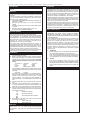 6
6
-
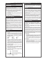 7
7
-
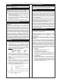 8
8
-
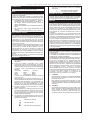 9
9
-
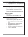 10
10
-
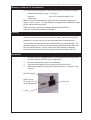 11
11
-
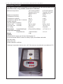 12
12
-
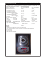 13
13
-
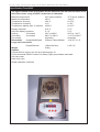 14
14
-
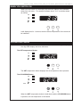 15
15
-
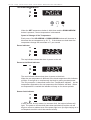 16
16
-
 17
17
-
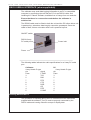 18
18
-
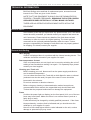 19
19
-
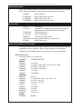 20
20
-
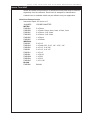 21
21
-
 22
22
-
 23
23


Keison TECHNE Tecal 425F Manual de usuario
- Tipo
- Manual de usuario
- Este manual también es adecuado para
en otros idiomas
Otros documentos
-
Techne TE-10D Manual de usuario
-
 MASS Engineered Design RU-200 Manual de usuario
-
ELICA EAR134S3 Elica Catalog 2018
-
Omega CL770A, CL780A, CL790A El manual del propietario
-
Ohaus HB1AL Manual de usuario
-
Whirlpool GT 385 MIR Guía del usuario
-
-
Tyco Kendall Genius 2 Operation And Service Manual
-
 Hansol Multitech D19AL Manual de usuario
-
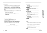 Hansol Multitech D17CL Manual de usuario


