O
ge.com
Water Filtration System
Sistema de Filtraci6n de Agua
GXSL55F GXSL55F
GXSV65F GXSV65F
Safety Instructions ............ 2
System Overview ........... 3-7
Installation Instructions..7-15
Battery Installation ............... 14
Faucet Installation ................ i0
Filter Replacement ............... 15
Flush Procedure .................. 15
Installing the Tubing .............. 13
Sgstem Installation ........... ii, 12
Water Supplg ................... 8, 9
Troubleshooting Tips ........ 16
Consumer Support ........... 20
Instrucciones deseguridad ..... 2
Generalidadesdelsistema .... 3-7
Instruccionesdeinstalaci6n ..7-is
Instalaci6n de la bateria .......... 14
Instalaci6nde la tuberia .......... 13
Instalaci6n del grifo .............. 10
Instalaci6ndel sistema ........ 11,12
Procedimientopara lavar ......... 15
Reposici6n del filtro ............... 15
Suministrodelagua ............. 8,9
Consejos para la soluci6n
de problemas ................. 17
Apoyo al consumidor ........ 19
GXSL55F is Tested and Certified bg NSF
International against NSF/ANSI Standard 42
for the reduction of Chlorine: Taste and Odor
and Particulate Class Iand Standard 53 for the
reduction of Lead, Cgst, Turbiditg, Asbestos,
Mercurg, Lindane, Atrazine, Toxaphene and 2,4-D.
El modelo GXSLggF se ha sometido a la prueba g
ha recibido la certificaci6n de NSFInternational
contra la norma 42 de NSF/ANSI para la reducci6n
de cloro: sabor g olor g clase I de particulas g la
norma 53 para la reducci6n de plomo, quistes,
turbidez, amianto, mercurio, lindano, atrazina,
toxafeno g 2,4-D.
GXSV65Fis Tested and Certified bg NSF
International against NSF/ANSI Standard 42
for the reduction of Chlorine: Taste and Odor
and Particulate Class Iand Standard 53 for the
reduction of Lead, Cyst, Turbidit U,Asbestos,
Mercurg, Lindane, Atrazine, Benzene and VOC.
El modelo GXSV65F se ha sometido a la prueba g
ha recibido la certificaci6n de NSFInternational
contra la norma 42 de NSF/ANSI para la reducci6n
de cloro: sabor g olor g clase I de particulas g la
norma 53 para la reducci6n de plomo, quistes,
turbidez, amianto, mercurio, lindano, atrazina,
bencina g VOC.
184DIO65PO0249-50233 IO-07JR

IMPORTANT SAFETYINFORMATION.
READ ALL INSTRUCTIONS BEFORE
USING.
A WARNING: Foruoursafetu,theinformationinthismanual
must be followed to minimize the riskof propertg damage or personal
injurg.
SAFETYPRECAUTIONS
[] Usethe Water Filtration sustem on a potable, safe-to-drink, home COLD
water supplu onlu. Thefilter canister will not purifu the water, or make it
safe to drink.
[] Do not useon a hot water supplU(IO0°Fmax.).
.Z_WARNING: Do not usewith water that is microbiologicallg
unsafe orof unknown quality without adequate disinfection beforeor after
the system.Systems certified for cystreduction may be usedon disinfected
water that may contain filterable cysts.
PROPERINSTALLATION
ThisWater Filtrationsystem must be properly installed and located in
accordancewith the InstallationInstructions beforeit isused.
[] Install or store where it will not beexposed to temperatures below
freezingor exposed to anUtupe of weather.Water freezing in the sustem
will damage it. Donot attempt to treat water over !00°R
WARNING: Discardall unusedand packaging material after
installation. Smallparts remaining after installation could bea chokehazard.
[] YourWater Filtrationsustem will withstand up to !20 pounds per square
inch (psi)water pressure.If your house water supply pressure ishigher
than !00 psi,install a pressure reducing valve before installing the Water
Filtration system.
READAND FOLLOW THISSAFETY
INFORMATIONCAREFULLY.
SAVE THESE INSTRUCTIONS
INFORMACION DE SEGURIDAD
IMPORTANTE.
LEA TODAS LAS INSTRUCCiONES ANTES
DE USAR.
-4LADVERTENCIA: Parasuseguridad,sedeber_seguirla
informaciGnde este manual para minimizar el riesgode dahosa la
propiedad o lesionespersonales.
PRECAUCIONESDESEGURIDAD
[] UseelSistemade FiltraciGndeAgua solamente en un suministrodeagua
potable FRiAque seasegura para elconsumo.Elcartucho delfiltro no
purificar6 elagua ni la har6 segurapara elconsumo.
[] No use en un suministro de agua caliente (]_00°FMGx.).
A
-&ADVERTENCIA: Nousecon aguaque sea
microbiolGgicamenteinseguraode calidaddesconocidasin unadesinfecciGn
adecuada delsistemaanteso despuds.Lossistemascertificadospara la
reducciGndeesporaspuedenser usadosen agua desinfectadaquepodria
contener esporasfiltrables.
INSTALACI()NCORRECTA
Estesistemade filtraciGndebeser instalado correctamente _Iubicado segE;n
las lnstruccionesde instalaciGnantesde suusa.
[] Instaleo almacene donde no est@expuesto a temperaturas par debajo
del punto de congelaciGno expuesto a ningOntipo de inclemencia
atmosf@ica.Siel agua se congela en elsistema IodaflarG. No intente
tratar el agua par encima de ]_00°R
-& ADVERTENCIA: Desechedespu_sdelainstalaci6ntodos
los materiales de empaquetado _Iaquellos queno fueron usados.Laspartes
pequehasquesobmndespudsdela instalacidnpodrian repmsentarun
peligro.
[] Susistema defiltraci6n de agua soportar6 hasta !20 libras par purgada
cuadrada (psi)de presi6n de agua. Sila presi6ndel suministro de agua de
sucasa esmayor de !00 psi,instale una v61vulareductora de presi6n
antes de instalar el sistema defiltraci6n de agua.
LEAYSIGACUIDADOSAHENTEESTA
INFORMACIONDESEGURIDAD.
CONSERVEESTASINSTRUCCiONES
2

Specifical:ions Guidelines.
Mang bad tastes and/or odors are removed from water using activated
carbon filter canisters.Theg aremost often usedto remove a chlorine taste
and odor.Theg can also reduce other undesirable elements from drinking
water supplies,such as organic chemical contaminants and lead.
NOTE:Small amounts of hydrogen sulfide (noticeable as "rotten egg" odor)
mag be reduced bg taste and odor filters for a short time, but the carbon
media is quickly exhausted Other water conditioning equipment is usually
required for the continuous treatment of hydrogen sulfide.
The Water Filtration System Uses the Following
Canisters
Model G,_SLggF
FQSLFFilter
(1200gallon capacitg)
Filter-White canisters with gellow band
* Reducesdirt, rustand sediment
* ReducesChlorine:Taste andOdor
* ReducesLead
* Reducesfilterable Cgsts(suchas crgptosporidium and giardia)
* ReducesTurbiditg
* ReducesAsbestos
* ReducesMercurU
* ReducesLindane
* ReducesAtrazine
* ReducesToxaphene
. Reduces2,4-D
.0.5-! micron nominal particulate reduction
Thissgstem conforms to NSF/ANSI/42and 53 for the specific performance
claims asverified and sustained bg test data. SeePerformance Data Sheet
for details.
Paul:as de las especificaciones.
Sepueden reducirmuchos malos olores g/o saboresdelagua usando
cartuchos de carbono para elfiltro. Seusan principalmente para reducir el
olor gsabor a clara.Tambi@npueden reducirotros elementos no deseados
delsuministro de agua, talescoma contaminantes quimicos org6nicos g
plomo.
NOTA:Se pueden reducir par poco tiempo pequehas cantidades de sulfuro
de hidr6geno coma elolaf a "huevo podrido" usando filtros de olaf y sabot,
pero el media de carbono se agota rdpidamente. Par Iogeneral, se requieren
otros equipos acondicionadores de agua para el tratamiento continua del
sulfuro de hidr6geno.
El sistema de filtraci6n de agua utiliza los siguientes
cartuchos
1'4odeloGXSL55F
Filtro FQSLF
(capacidad de !200 galones)
Filtro-cartuchos blancos con banda amarilla
* Reducela suciedad,el 6xido g lossedimentos
* Reduceel sabor golor acloro
* Reduceel plomo
* Reducelos quistes filtrables (como cristosporidium ggiardia)
* Reducela turbidez
* Reduceel amianto
* Reduceel mercurio
* Reduceel lindano
* Reducela atrazina
* Reduceeltoxafeno
* Reduce2,4-D
* Reducci6n nominal de particulas de 0,5-! micr6n
Estesistema se conforma alas normas/42 g 53 NSF/ANSIen cuanto
alas afirmaciones especificasde desempeflo segOnverificaci6n
gadmisi6n de losdatos de las pruebas. Consultela hoja de datos del
desempeSo para detalles.

Specifications Guidelines.
The Water Filtration System Usesthe Following
Canisters
Model GXSV55F
FQSVFFilter
(160gallon capacitg)
Filter-White canisters with green band
* Reducesdirt, rustand sediment
* ReducesChlorine:Taste andOdor
* ReducesLead
* Reducesfilterable Cgsts(suchas crgptosporidium and giardia)
* ReducesTurbiditU
* ReducesAsbestos
* ReducesMercurU
* ReducesLindane
* ReducesAtrazine
* ReducesBenzene
* ReducesVOC
* 0.5-1 micron nominal particulate reduction
Thissgstem conforms to NSF/ANSI/42and 53 for the specific performance
claims asverified and sustained bg test data. SeePerformance Data Sheet
for details.
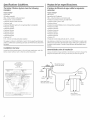
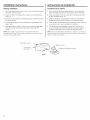
Installation Overview
Locate thedrinking water system on the cold water supply pipe,under the
kitchenand/or bathroom sink,to filter the cold drinking water.
Pautas de los especificaciones.
Elsistema de filtraci6n de agua utiliza los siguientes
cartuchos
Modelo GXSV65F
Filtro FQSVF
(capacidad de 160 galones)
Filtro-cartuchos blancos con banda verde
* Reducela suciedad,el 6xido g lossedimentos
Reduceel sabor golor acloro
Reduceel plomo
Reducelos quistesfiltrables (como cristosporidium ggiardia)
Reducela turbidez
Reduceel amianto
Reduceel mercurio
Reduceel lindano
Reducela atrazina
Reducela bencina
ReduceVOC
Reducci6n nominal de particulas de 0,5-1 micr6n
Estesistema se conforma alas normas/42 g 53 NSF/ANSIen cuanto alas
afirmaciones especificas de desempeflo segOnverificaci6n g admisi6n de
los datos de las pruebas. Consulte la hoja de datos deldesempeflo para
detalles.
Generalidades sobre la instalaci6n
Coloqueel sistemade agua potable en latuberia de suministrode agua fria,
debajo dellavaplatos de lacocina £/o del baho para filtrar elagua ffia.
Stale of C difomil
Dep mmerlt of Healtll Selvices
Waler Treatment Device
Ceilificale Number
04- 1600
Da_ Issued [ eb, u _ry 9 2_)4
] radelnalk Model l)esi_nation Rt, JlavenlentI lenlentx
<:;xstss F ir_S£F
Sink/
Lavaplatos
Hot/ Cold/
Caliente Fr[a
Water Supply Valve /
Wlvula de suministro de agua
FilteredWater Faucet/
Grifodeaguafiltrada
/
Recolector
Outlet/
Salida
FilterCanisters/
Cartuchosdelosfiltros
4

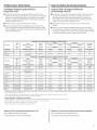
Performance Data Sheet.
SmartWater Filtration systemGXSL55F
Using Filter FQSLF
[] This Sustem has been tested according to NSF/ANSI 42 and 55 for the
reduction of the substances listed below. The concentration of the indicated
substances in water entering the sustem was reduced to a concentration
less than or equalto the permissiblelimit for water leavingthe sustem,as
specified in NSF/ANSI 42 and 55.
[] Actual performancema U var U with local water conditions.
[] Do not use with water that is microbiologicallUunsafe or with water of
unknown qualitUwithout adequatedisinfection before or after the sustem.
Sustemscertified for cUstreduction ma U be used on disinfected waters that
ma U contain filterable custs.
Hoja de datos de funcionamiento.
Cartucho FQSLFde sistema de filtraci6n
GESmartWater GXSL55F
[] Estesistemasehasometidoalas pruebasNSF/ANSI/42y 53afin dereducir
lassustanciaspresentadasacontinuaci6n.Seredujola concentraci6n
delas sustanciasindicadasenel aguaque ingresanenel sistemaa una
concentraci6nmenoroigualal limitepermitidopara elagua que saledel
sistema,comaseespecificaenNSF/ANSI42 y 53.
[] Eldesempeflorealpuedevariarde acuerdoalascondicioneslocales
delagua.
[] No use con agua quesea microbial6gicamente insegura ode calidad
desconocida sinuna desinfecci6nadecuada delsistema anteso despu@s.
Lossistemascertificados para la reducci6nde esporaspueden set usados
en agua desinfectada que podria contener esporasfiltrables.
Parameter
Par4metro
Chlorine/Clara
T&O
Particulate**/
Particulas
USEPA
MCL
USEPA
MCL
Standard No. 42: Aesthetic Effects t Est6ndor No. 42: Efectos est_ticos
Influent
Average
Promedio
influ_ente
1.89 mg/L
5700000 #/mL
Influent
Challenge Concentration
Calidad del
influ_ente concentraci6n
2.0 mg/L +_10%
> 10000 particles/
particulas/mL
Effluent
Average Maximum
Effluq,ente
Promedio MSximo
<0.05 mc)/L 0.06 mg/L
30583 #/mL 69000 #/mL
w
w
Standard No. 53: Health Effects t Est6ndar No. 53: Efectos relativos a la salud
Influent
Average
Promedio
influ_ente
10.73 NTU
166500 #/L
155 HF/L
0.152 mg/L
0.148 mg/L
0.006 mg/L
0.006 mg/L
0.002 mg/L
0.015 mg/L
0.222 mg/L
0.00886 mg/L
USEPA Influent
Parameter MCL Challenge Concentration
USEPA Calidad del
Par5metro MCL influ_ente concentraci6n
Turbidit_/Turbidez 1 NTU*** 11 +_1 NTU***
CL)StS/OUistes 99.95% red. lin. 50000L
Asbestos/Amianto 99% red. 107and/g 108fibers/fibras/L;
fibers/fibras >10 pm
long/de largo
Lead/Homo, 0.015 mg/L 0.15 mg/L +_10%
pH 6.5
Lead/Homo, 0.015 mg/L 0.15 mg/L +_10%
pH 8.5
Hercurg/Hercurio, 0.002 mg/L 0.006 mg/L +_10%
pH 6.5
Hercurg/Hercurio, 0.002 mg/L 0.006 mg/L +_10%
pH 8.5
Lindane 0.0002mg/L 0.002 mg/L +_10%
Toxaphene 0.003mg/L 0.015 +_10%
2,4-D 0.0017mg/L 0.021 mg/L +_10%
Atrazine 0.003 mg/L 0.009 mg/L +_10%
Effluent
Average
Efflu_tente
Promedio M_ximo
0.311 NTU 0.49 NTU
<1 <1
<i <i
<0.001 <0.001
<0.001 <0.001
0.00024 0.0005
0.0007 0.0013
0.000025 0.00002
<0.001 <0.001
0.01/422mg/L 0.059 mg/L
<0.002 <0.002
% Reduction
Average Minimum
% de reducci6n
Promedio Minima
>97.29% 96.84%
99.52% 98.94%
% Reduction
Maximum
Average Minimum
% dereducci6n
Promedio Minima
97.08% 95.15%
>99.99% >99.99%
>99.99% >99.99%
>99.34% >99.29%
>99.31% >99.29%
98.72% 99.31%
87.37% 79.63%
98.97% 98.89%
93.23% 91.67%
93.14% 70.50%
77.33% 76.61%
Min. Required
Reduction
Reducci6n
minima necesaria
>50%
>85%
Min. Required
Reduction
Reducci6n
minima necesaria
0.5 NTU
>99.95%
99%
0.01 mg/L
0.01 mg/L
0.002 mg/L
0.002 mg/L
0.0002 mq/L
0.003 mg/L
0.0017 mq/L
0.003 mg/L
*Tested using a flow rate of 0.78 gpm (2.95 I/min); pressure of 60 psig; pH of 7.5+_0.5;temp. of 68° +_5°F{20° +_3°0 / Probado utilizando una tasa de flujo de 0,78 gpm {2,95 I/min); presi6n de 60 psig;pH
de 7,5+_0,5;temp. de 68° +_5° F (20° +_3° C}
**Measurement in partides/mL Particles usedwere 0.5-1 microns. / Hedici6n en partkulas/mL Los partkulus usadus erun de 0,5-1 micr6n.
***NTU-Nephelometric Turbiditg Units / NTU-unidades de turbidez nefelom@rica
Operetinq Specifications / Especificociones de operoci6n
Capacitg: certified for up to 1200 gallons (4,542 I);up to six months / Capacidad: certificado para hasta 1200 galones {4542 I);hasta seis mesas
Pressure requirement: 35-120 psi(2.8-8.2 bar) / Requerimientos de presi6n: 35-120 psi{2,8-8,2 bar}
Temperature: 33-100°F (0.6-38°C)/ Temperatura: 33°-100 ° F{0,6°-38° C}
Flow rate: 0.78 gpm (2.95 I/min)/ Tasa de flu]o: 0,78 gpm {2,95I/min)
Replacement Niter Canisters/Estimated Replacement Costs
FQSLF-Replacement filter canister $50-55
Forreplacement parts,call toll-free800.626.2002.
Repuestode los cartuchos de losfiltros/Costos estimados de reposici6n
FOSLF-Repuestodelcartucho delfiltro $50-55
Pararepuestos,Ilamegratis a1800.626.2002(EE.UUJ.
5

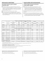
Performance Data Sheet.
SmartWater Filtration systemGXSV65F
Using Filter FQSVF
[] This System has been tested according to NSF/ANSI 42 and 55 for the
reduction of the substances listed below. The concentration of the indicated
substances in water entering the system was reduced to a concentration
less than or equalto the permissiblelimit for water leavingthesystem,as
specified in NSF/ANSI 42 and 55,
[] Actual performancemay vary with local water conditions.
[] Do not use with water that is microbiologicallyunsafe or with water of
unknown quality without adequatedisinfection before or after the system.
Systemscertified for cyst reduction may be used on disinfected waters that
may contain filterable cysts.
Hoja de dates de funcionamiento.
Cartucho FQSVFde sistema de filtraci6n
GESmartWater GXSV65F
[] Estesistemasehasometidoalas pruebasNSF/ANSI42 y 53afin
dereducir lassustanciaspresentadasacontinuaci6n.Seredujola
concentraci6nde lassustanciasindicadasenel agua queingresanen
el sistemaauna concentraci6nmenoro igualal limitepermitidopara
el aguaque saledelsistema,comese especificaen NSF/ANS142y 53.
[] Eldesempeflorealpuedevariar deacuerdoalas condicioneslocales
delagua.
[] No usecon agua quesea microbiol6gicamente insegura ode calidad
desconocida sinuna desinfecci6nadecuada delsistema anteso despu@s.
Lossistemascertificados para la reducci6nde esporaspueden ser usados
en agua desinfectada que podria contener esporasfiltrables.
USEPA
Parameter MCL
USEPA
Par6metro MCL
Chlorine/Cloro
T&O
Particulate**/
Partkulas
Standard No, 42: Aesthetic Effects / Est6ndar No, 42: Efectos est_ticos
Influent
Challenge Concentration
Calidad del
influ_lente concentraci6n
2.0 mg/L +_10%
> 10000 particles/
partkulas/mL
Influent
Average
Promedio
influ_!ente
1.94 mg/L
4100000 #/mL
Standard No. 53: Health Effects
Turbidit_/Turbidez 1 NTU*** 11 +_1 NTU***
C_sts/Ouistes 99.95% red. Nin. 50000L
Asbestos/Amianto 99% red. 107 and/y 10_ fibers/fibres/L;
fibers/fibres >10 pm
long/de largo
Lead/Plomo, 0.015 mg/L 0.15 mg/L +_10%
pH 6.5
Lead/Plomo, 0.015 mg/L 0.15 mg/L +_10%
pH8.5
Hercurg/Hercurio, 0.002 mg/L 0.006 mg/L +_10%
pH 6.5
Hercury/Hercurio, 0.002 mg/L 0.006 mg/L +_10%
pH 8.5
Lindane 0.0002 mg/L 0.002 mg/L +_10%
Benzene 0.001 mg/L 0.015 mq/L +_10%
Atmzine 0.003 mg/L 0.009 mg/L +_10%
VOCReduction / Reducci6n de VOC
Chloroform I 0.080 mq/L I
11.08NTU
141750#/L
168MF/L
0.147 mg/L
0.143 mg/L
0.006033333 mg/L
0.0058 mg/L
0.002016667 mg/L
0.01417 mg/L
0.00830 mg/L
Effluent
Average Maximum
Effluyente
Promedio Mbximo
<0.05 mg/L <0.05 mg/L
24400 #/mL 67000 #/mL
'Est6ndor No. 53: Efectos relatives a la solud
0.21 NTU
< 1 #/L
0.99885891 IF/L
<0.001 mg/L
<0.001 mg/L
<0.0002 mg/L
0.000333 mg/L
<0.00002 mg/L
0.000500 mg/L
0.002000 mg/L
% Reduction
Average Minimum
% dereducci6n
Promedio Minimo
97.41% 97.22%
99.35% 97.84%
0.38 NTU 98.04%
2 #/L >99.99%
<1 HF/L 99.89%
<0.001 mg/L 99.32%
<0.001 mg/L 99.50%
<0.0002 mg/L 96.68%
0.0005 mg/L 94.34%
<0.00002 mg/L 99.00%
0.000500 mg/L 96.47%
0.002000 mg/L 74.82%
96.20%
>99.99%
99.82%
99.29%
99.29%
96.49%
92.06%
98.95%
96.43%
61.54%
Min. Required
Reduction
Reducci6n
minima necesaria
>50%
>85%
0.5 NTU
>99.95%
>99%
0.010 mg/L
0.010 mg/L
0.002 mg/L
0.002 mg/L
0.0002 mg/L
0.005 mg/L
0.003 mg/L
0.30 +_10% 0.31429 mg/L 0.00186429 mq/L 0.0055 mq/L 99.40% 98.28% 95%
*Tested using a flow rate of 0.60 gpm (2.27 I/min); pressure of 60 psig; pH of 7.5+_0.5;temp. of 68° +_5°F {20° +_3°0 / Probado utilizando una tasa deflujo de 0,60 gpm {2,27 I/min); presi6n de 60 psig; pH
de 7,5+_0,5;temp. de 68° +_5° F(20° +_3° C)
**Measurement in particles/mL Partides usedwere 0.5-1 microns. / Hedici6n en particulas/mL Los partkulas usadas eran de 0,5-1 micr6n.
***NTU-Nephelometric Turbidit9 Units / NTU--unidades de turbidez nefelom6trica
Operating Specifications t Especificodones de operoci6n
Capacity: certified for up to 160 gallons (605I);upto six months / Capacidad: certificado para haste 160 galones {605 I);haste seis moses
Pressure requirement: 35-120 psi (2.8-8.2 bar) / Requerimientos de presi6n: 35-120 psi{2,8-8,2 bar)
Temperature: 33-100°F (0.6-38°0 / Tempemtura: 33-100 ° F(0,6°-38° C)
Flow rate: 0.60 gpm (2.27 I/min)/ Tasa de flujo: 0,60 gpm {2,27I/min)
Replacement Filter Canisters/Estimated Replacement Costs
FOSVF-Replacementfilter canister$55-40
Forreplacement parts,call toll-free800.626.2002.
Repuestode los cartuchos de losfiltros/Costos estimados de reposici6n
FQSVF-Repuestodelcartucho delfiltro $55-40
Pararepuestos,Ilamegratis al 800.626.2002(EE.UU.).
6

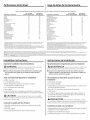
Performance Data Sheet.
Hoja de datos de funcionamiento.
Organic Chemicals Reduced bg Chloroform Surrogate Testing /Quimicos org6nicos reducidos per la prueba sustituta de cloroformo
Avg. / Promedio 1 Max. Effluent /
Contaminant / Contaminante Influent / Influgente (IJg/L)2 Efflugente (iJg/L) 2 Contaminant / Contaminante
Alachlor 50 1.0s Haloketones (HK):
Atrazine 100 3.0s 1,1-dichloro-2-propo none
Benzene 81 1.0s 1,1,1-tdchloro-2-propa none
Carbofuran 190 LO s Heptachlor (H-34, Heptox)
Carbon Tetrachlodde 78 1.8_ Heptochlor Epoxide
Chlorobenzene 77 1.0s Hexochlorobutodiene
Chloropicdn 15 0.24 Hexoc hlorocgclopentodiene
2,4-D 110 1.7_ Lindone
Dibromochloropropane (DBCP) 52 0.02 s Hethoxgchlor
o-Dichlorobenzene 80 LO s Pentachlorophenol
p-Dichlorobenzene 40 1.Os Simazine
1,2-Dichloroethane 88 4.8s Styrene
1,1-Dichloroethylene 83 LO s 1,1,2,2-Tet rachloroetha ne
cis- 1,2-Dichloroet hglene 170 0.5s Tetrachloroethglene
trans- 1,2-Dichloroet hylene 86 LO s Toluene
1,2-Dichloropropane 80 LO s 2,4,5-TP (siDex)
cis- 1,3-Dichloropropylene 79 LO s Tribromoacetic acid
Dinoseb 170 0.24 1,2,4-Trichlorobenzene
Endrin 53 0.59_ 1,1,1-Trichloroet hane
Ethylbenzene 88 LO s 1,l,2-Trichloroet hane
Ethylene Dibromide (EDB) 44 0.02 s Trichlorothylene
Haloacetonitriles (HAN): Trihalomethanes (includes):
Bromochloroacetonitrile 22 0.5_ Chloroform (surrogate chemical)
Dibromoacetonitrile 24 0.64 Bromoform
Dichloroacetonitdle 9.6 0.24 Bromodichloromethane
Trichloroacetonit rile 15 0.5_ Chlorodibromomethane
Xylenes (total)
Avg. / Promedio 1 Max. Effluent /
Influent / Influgente (Hg/L) 2 Efflugente (Hg/L) 2
72 0.1_
826 0.3_
80 0.4s
10.76 0.26
44 Lo s
60 0.002 s
55 O.Ols
50 0.is
96 LO s
120 4.0s
150 0.5s
81 LO s
81 LO s
78 LO s
270 1.6s
42 LO s
160 0.5s
84 4.6_
150 0.5s
180 LO s
300 15
70 LO s
1Infiuent challenge levels are average influent concentrations determined insurrogate quafificotion testing. /
Los nivdes de rata infiugente son cancentreciones influgentes promedia determinodos en pruebos de
calificaci6n sustitutos.
2Hg/L means Micrograms Per Liter./pg/L significa microgromos par litra.
3Maximum product water level was not observed but was set at the detection limit of the analysis. / El nivel
mdxima del oguo del producta no se observ6 pero rue colacada a un Iimite de detecciGn pare el ondlisis.
Maximum product level is set at a value determined in surrogate qualification testing. / El nivel mdxima del
producto es colacada a un valor determinodo par Io prueba de calificociGn sustituta.
sChemical reduction percent and maximum product water level calculated at chloroform 95% breakthrough
point as determined in surrogate qualification testing. / El porcentoje de la reducciGn quimico g el nivel
mdxima del oguo del producto calculada a un punto de rupturo de 95% de claroforma segOn la
determinado en Io prueba de calfficociGn sustituta.
6The surrogate test results for heptachlor Epaxide demonstrated a 98% reduction. These data were used to
calculate an upper occurrence concentration, which would produce o maximum product water level at the tCL. /
Losresultados de lapruebo de sustituciGn pora el Epaxida heptoclaro demostraron uno reducciGn de 98%. Estos
dotos fueron usados para colculor la ocurrencia de uno concentraciGn superior, Io qua produciria un nivel mdxima
de aguo del producto en el HCL.
Testing was performed under standard laboratory conditions; actual performance may vary. / La prueba fue Ilevada a cabo bajo condiciones de laboratorios est6ndares; el rendimiento real podfia variac
NOTE:Substances reduced are not necessarily in your water Filter must be maintained according to manufacturer's instructions, including replacement of filter cartridges. / NOTA: Lassustancias reducidas no est6n necesariamente en su
agua. Elfiltro debe mantenerse de acuerdo con las instrucciones del fabricante, inclugendo los cartuchos de reemplazo.
WARNING: Do not usewith water that is microbiologically unsafe or of unknown quality without adequate disinfection before or after the system. Systems certified for cyst reduction may be used on disinfected waters that contain
filterable cysts. / ADVERTENCIA: No use con agua qua no sea microbiolGgicamente segura o de calidad desconocida sin desinfecciGn adecuada antes g despuGs del sistema. Los sistemas certificados para la reducciGn del quiste
poddan usarse en aguas desinfectadas que contienen quistes filtrable&
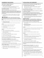
Installation Instructions.
Important Installation Recommendations
A WARNING: headentiremanual.Failureto followallguides
and rulescould causepersonal injury or property damage.
[] Check with your local public works department for plumbing codes.
You must follow their guides us you install the Water Filtration
system.
Tools and Materials Required for Installation
* Phillips screwdriver
* Two (2)adjustable wrenches
* Electric drill and drillbit to drill3/4" hole (type as required)
ifmounting hole is needed for faucet
* 1/16" drillbit (optional for pilot holes)
.Tape measure
* Ifyour main water line isa rigid pipe, you will require a compression
fitting and possibly other plumbing hardware to complete the installation.
A CAUTION: :o avoid damaging the sink, consult a qualified
plumber or installerfor drilling procedures. Specialdrillbits ma_lbe needed
for porcelainor stainlesssteel.
Contents Included with the Product
. Water filter system assembly, including mounting screw and double-
sided tape
. Feed water adapter
. Faucet assembly with electronic base monitor and tubing
instrucciones de instalaci6n.
Recomendaciones importantes para la instalaci6n
A ADVERTENCIA: Leael manual completo. No seguir todas
los pautas _Ireglaspodria causar lesionespersonales_Ia la propiedad.
[] Consulte con su departamento local de obras pSblicas para los
c6digos de plomeria. Usted debe seguir estas pautas a medida qua
instala el sistema de filtraci6n de agua.
Herramientas y materiales necesarios para la
instalaci6n
. Destornillador de estrella
. Dos (2)Ilavesajustables
. Taladro el_ctrico y broca para el taladro para perforar un orificio de 3/4"
paraelgrifo(deltiponecesario)
. Broca de 1/16" para taladro (opcional para orificios piloto)
. Cinta m_trica
. Sisulinea de agua principal esdetuberia rigida, usted necesitar6 un
accesorio de compresiGny posiblemente alguna otra herramienta de
plomeria para completar la instalaciGn.
A PRECAUCION: Para evitar dahosa//avap/atos, consu/te
con unplomero o insta/adorcdificado para losprocedimientosdeperforociGn.
Podrian necesitarse brocas especiales para porcelana o acero inoxidable.
Contenido incluido con el producto
. Ensambladura del sistema de filtraci6n de agua, inclugendo eltornillo de
instalaci6n g cinta con doble adhesivo
. Adaptador para la alimentaci6n de agua
. Ensambladuradelgrifoconunmonitordebaseelectr6nicog tuberia
7

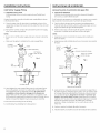
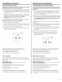
Installation Instructions.
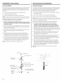
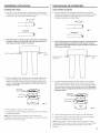
Cold Water Supply Fitting
A. PREFERREDINSTALLATION
(Utilizingexisting kitchen sink water supply valve and flexible faucet
tubing)
Atgpical connection using the included water supplg fitting is shown
in the illustration below.
1. Close the water shut-off valve that is immediatelg in front of the
supplg tube and open the faucets to drain water from the sink cold
water pipe.
2. Remove the nut that connects the cold water faucet to the supplU
tube. Some water mag spill out.
NOTES:
• Besure to turn off the water supplg and open a faucet to drain the
pipe.
,, Make sure the gasket is installed in the water supplg fitting.
ColdWater
FaucetStud
asket
Water Supply Fitting
1/4"Tubingto
_ WaterFilterInlet
Water Pipe _ _v<..4] I
,i
ColdWaterShutoff
f i
3,
4,
5.
Hand-tighten the water supplg fitting onto the cold water faucet.
Be sure the gasket, as shown, is in place before final assemblg.
Finish tightening with an adjustable wrench. Be cureful not to
overtighten or cross-threud, us dumoge to the threuds con
occur. Make sure the !/4" quick connection is not against a wall
that causes the supplg tubing connection to bend. Aquarter turn to
tighten or loosen the adapter mag be necessarg to avoid this.
Reconnect faucet tubing line to the fitting.
Install tubing. (SeeInstalling the Tubing section.)
instrucciones de instalaci6n.
Accesorio para el suministro de agua fria
A. INSTALACIONPREFERIDA
(Utilizando la vdlvula existente de suministro de agua del lavaplatos
de lacocina £ la tuberia flexible delgrifo)
En la ilustraci6n que aparece a continuaci6n se muestra una conexi6n
tipica usando el accesorio para el suministro de agua incluido.
1. Cierre la v61vulade agua que se encuentra inmediatamente en
frente del tubo de suministro L!abra los grifos para dejar correr el
agua de la tuberia de agua fria del lavaplatos.
2. Retire la tuerca que conecta el grifo de agua fria al tubo de
suministro. Es posible que se derrame un poco de agua.
NOTAS:
,, AsegOrese de cerrar el suministro de agua g abra el grifo para
drenar la tuberia.
,, AsegOrese que est@instalada lajunta en el accesorio de suministro
de agua.
3,
Perno del
grifo de
agua fria
Tuer
aguafria _ _J_]
V_lvula de cierre de agua fria
_ Junta
'__ Accesoriode suministrodeagua
by-f" ,_ Tubode1/4"a entrada
_. del filtro deagua
Fig. 1
f i
Ajuste en forma manual el accesorio de suministro de agua fria en
el grifo de agua fria. AsegOreseque lajunta, como se muestra, est_
en su lugar antes del ensamble final. Termine de colocar la misma
con una Ilave de ajuste. Aseg(_rese de no forzur ni presionor por
demos u fin de evitur duffer Io roscu. AsegOrese que la conexi6n
rSpida de !/4" no est_ contra una pared que hugo que la conexi6n
del tubo de suministro se tuerza. Esposible que se necesite
presionar o aflojar el adaptador con un cuarto de giro a fin de
evitar esto.
4. Vuelva a conectar la tuberia del grifo al accesorio.
5. Instale la tuberia. (Consulte la secci6n de Instalaci6n de la tuberia.)
8

Installation Instructions.
Cold Water Supply Fitting (cont.)
B. OPTIONALHOMEINSTALLATION
{Wherecodespermit)-Saddle Valve:Saddlevalvemust be able
to connect with 1/4-inch tubing supplied with system.
Not supplied with product; check gour local hardware or home
service store for product
Saddle valve typically requires 1/2"0D tubing or larger.
NOTE: Codes in the state of Massachusetts require installation bg a
licensed plumber and do not permit the use of the saddle valve. For
installation, use plumbing code 248-CNR of the Commonwealth of
Massachusetts.
1. Turn offthe cold water supplUand install saddlevalve as required
by product selection. (Besure to follow manufacturers' installation
instructions.)
.4LDANGER: If hole is required to be drilled in pipe, to
protect yourself from serious injury or fatal shock, use a battery
powered hand drill onlg to make the hole. DO NOT USE AN ELECTRIC
DRILL.
2. Open saddle valve onlg after complete sgstem has been installed.
C. OPTIONALINSTALLATION
(Forinstallation with rigid pipe between supply valve and sink faucet)
Option 1
1. Remove pipe from supplg valve and sink faucet.
2. Obtain flexible pipe sized to gout plumbing.
3. Install flexible pipe.
4. Go back to A.Preferred Installation section step 3.
Option 2
1. Obtain compression fittings to fit rigid pipe.
2. Obtain ang other fittings required to connect compression fittings
to feed water adapter.
3. Remove pipe from supplg valve.
4. Cut pipe to fit length of assembled fittings and adapter.
5. Install compression fitting to pipe.
6. Go back to A.Preferred Installation section step 3.
NOTE:Above described materials ere not included with the product.
Faucet Spout Installations (seeFig.2,page10)
1. Removespout (A)andfaucet bodg (B)from faucet packaging.
2. Hove the threaded dome-shaped collar (C)on the spout up and awag
from the o-rings on the spout.
3. Gentlginsert the spout into the top of the faucet bodg.
NOTE:Turning the spout left to right during installation will help the
o-rings to slide in easilg.
4. Once the spout (A)has been installed and fullg seated, slide the
threaded collar (C)down to the faucet bodg (B).
5. Tighten the collar bg hand to the faucet badUbg turning in a
clockwise direction.
instrucciones de instalaci6n.
Accesorio para el Suministro de Agua Fria (cont.)
B. INSTALACION OPCIONAL EN ELHOGAR
(Donde Io permitan los c6digos)-Vdlvula de asiento: La vdlvula de
asiento debe poder conectarse con el tuba de 1/4 de pulgada
suministrado con el sistema
No se suministra con el producto; consulte en la ferreteria local o
tienda de servicios para el hogar.
La v_lvula de asiento tipicamente requiere una tuberia con un diSmetro
exterior de 1/2" o superior.
NOTA: Los c6digos del estado de Massachusetts exigen la
instalaci6n par parte de un plomero con licencia g no permite el usa
de una v61vula de asiento. Para la instalaci6n, utilice el c6digo de
plomeria 248-CMR del estado de Massachusetts.
1. Cierre el suministro del agua fria e instale la v61vula de asiento segOn
Io requiera el producto (Cerci6rese de seguir las instrucciones de
instalaci6n del fabricante).
PELIGRO: sisenecesitataladrarunagujeroenla
tuberia, para protegerse contra lesiones serias o choques fatales,
utilice _nicamente un taladro manual operado par bateria para
perforar el orificio. NO UTILICE UN TALADRO ELECTRICO.
2. Abra la v61vulade asiento Onicamente despu_s de haber instalado
todo el sistema.
C. INSTALACION OPCIONAL
IPara la instalaci6n con una tuberia rigida entre la vdlvula de suministro
_Ielgrifo del lavaplatos)
Opci6n 1
1. Remueva la tuberia de la v61vulade suministro gdel grifo del lavaplatos.
2. Obtenga tuberia flexible con un tamaSo acordecon sutuberia
de lacasa.
3. Instale latuberia flexible.
4. Refi@aseaA.Secci6nde instalaci6n preferidaen elpaso 3.
Opci6n2
1. Obtengaaccesoriosdecompresi6nparahacerelajustedela
tuberiarigida.
2. Obtengacualquieraccesoriorequeridoparaconectareladaptador
decompresi6naladaptadorparalaalimentaci6ndeagua.
3. Remuevalatuberiadelavcilvuladesuministro.
4. Carte latuberia para que seajuste ala Iongitud de losaccesorios
ensamblados gal adaptador.
5. Instaleel accesorio de compresi6n ala tuberia.
6. Refi@aseaA.Secci6nde instalaci6n preferidaen elpaso 3.
NOTA:Los materiales descritos anteriormente no est6n incluidos con
el producto.
Instalaci6n del pica del grifo (verFig.2, p6gina 10)
1. Retireel pica (A)g piezadel grifo (B)del paquete del grifo.
2. Hueva elcollar enroscado enforma decopula (C)en el pica hacia arriba
g lejosde los aros t6ricos en el pica.
3. Suavemente inserteel pica en la parte superior de la pieza del grifo.
NOTA: Girar el pica de la izquierda a la derecha durante la
instalaci6n agudar6 a qua los aros t6ricos se deslicen f6cilmente.
4. Una vez que el pica (A)se haga instalado g est_ completamente
acomodado, deslice el collar enroscado (C)hacia abajo en direcci6n
de la pieza del grifo (B).
5. Apriete el collar a mano a la pieza del grifo girando en la direcci6n
del reloj. 9

Installation Instructions.
Faucet Installation
Besurethere is room underneath and above the sink to make the needed
connections. Beforestarting, make surethere issufficient room for the
battery powered faucet base.Selectone of the following places to install
the faucet:
1. Inan existing sink sprag attachment or soap dispenser hole.
Z Ina hole to be drilled inthe sinktop.
3. Ina hole to be drilled inthe countertop, next to the sink.
NOTE:Be sure the faucet base will fit fiat against the surface at the selected
location so the bottom gasket between the base and surface area willseal.
Instolletion Steps (refer to Fig. 2 for clarification)
1. Ifdrilling is needed, make a 3/4" diameter hole,
Be sure to use the proper procedure for drilling porcelain or stainless
steel. Special drill bits meg be needed. Consult o quelified plumber for
the proper procedure.
2. Remove the faucet with pre-installed tubing, thin o-ring (D),faucet base
(E),bottom bose gasket (F),lock washer (G),hex nut (H)and mounting
bracket (I)from the packaging,
3. Feed tubing connected to the faucet through the thin o-ring (D),faucet
bose (E),bottom bose gasket (F),lockwasher (G)and hex
nut (H).
4. Thread the hex nut (H)up the stem of the faucet untilthe height
between the bottom of the basegasket (F)andtop of the lockwasher
(G)isslightlg larger than the thickness of the mounting surface (J).
5. Lower the faucet assemblg into place in the mounting hole and
orient to final position. Place the mounting bracket (I)above the
lock washer (G)around the faucet stem (Fig.3).While holding the
mounting bracket in place, securelg tighten the hex nut.
NOTE:Two people may be required to complete this step.
instrucciones de instalaci6n.
Instuluci6n del grifo
Cerci6rese de que haga suficiente espacio debajo g encima del lavaplatos
para realizar laconexi6n necesaria.Antes de empezar,cerci6rese de que
haua suficiente espacio para la base del grifo operada per bateria.
Seleccioneuno de los siguientes lugares para instalar elgrifo:
1. Enun orificio accesorio rociador existente en ellavaplatos uorificio de
dispensador dejab6n.
2. Enun orificio a perforar en la parte superior del lavaplatos.
3. Enun orificio a perforar en el mostrador, al lade del lavaplatos.
NOTA:Cercidresede que la base delgrifo quedeplana contra la superficieen
la ubicacidnseleccionadade manera que el empaque deabajo entre labase
gel dma de la superficiequedesellado.
Pasos para la instoloci6n (consulte la Fig. 2 pore ocluroci6n)
1. Si es necesario perforar, haga un orificio de 3//4"de di6metro.
Cerci6rese de utilizer el procedimiento correcto pure perforur
porcelono o ocero inoxidoble. Podr[e necesitor braces odicionoles.
Consulte a un plomero calificedo pare el procedimiento correcto.
2. Retire del paquete el grifo con la tuberia preinstalada, are t6rico fine (D),
base del grifo (E),empaque inferior de la base (F),arandela de seguridad
(G),tuerca hexagonal (H)g soporte de montaje (I).
3. Inserte latuberia conectada al grifo atroves delare t6rico fine (D),la
basedel grifo (E),el empaque inferior de la base(F),laarandela de
seguridad (G)g latuerca hexagonal (H).
4. Enrosque la tuerca hexagonal (H)en el v6stago del grifo hasta que la
altura entre la parte inferior del empaque de labase (F)g la parte
superior de laarandela de seguridad (G)sea ligeramente m6s grande
que elgrosor de la superficie de montaje (J).
5. Bajela ensambladura del grifo asu lugar en elorificio de montaje g
oriente hacia laposici6n final. Coloqueel soporte de montaje (I)par
encima de laarandela de seguridad (G),alrededor delv6stago delgrifo
(Fig.3).Mientras sostieneel soporte de montaje en su lugar,apriete
firmemente la tuerca hexagonal.
NOTA:Esposibfeque seannecesariasdospersonaspara completar
este paso.
(B)Faucetbody/
Piezadel grifo
(G)Lockwasher/
ArandeladesegurJdad
(H)Hexnut/
Tuercahexagonal
(I)Mounting
bracket/
Soportede
montaje
(A)Spout/ Pica
(C)Collar/ Collar
(D)O-ring/ Aret6rico
(E)Faucetbase/ Basedel grifo
(F)Gasket/ Empaque
(J)Mountingsurface/
Superficiedemontaje
Fig. 2
:!• ::
<::::::>
Fig. 3
10

Installation Instructions.
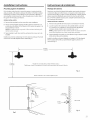
Mounting System Installation
Picka locationunder the sink to mount the system. Location should be
easilgaccessible,with clearance between the bottom ofthe filter canisters
and the floor or bottom of the cabinet; ang lesswill resultin difficultUof
removing filter canisters (seeFig.S).Allow enough spaceon either sideof
the sgstem for the tubing connections.
SCREW INSTALLATION
1,
2.
Removethis template from the manual for easier installation.
The top of the template openings should be placed a minimum of 17
inches above the bottom of the cabinet or floor where the sgstem isto
be mounted (Fig./4and 5).
NOTE:Any distance lower may resultin filter canisters interfering with
the floor when removed.
3. Tapetemplate to wall,then mark the wall where the screws areto be
installed.
Install screws into the wall, leaving 3/16 inch clearance between the head
of the screw and wall (drill pilot holes if needed)(Fig.6).
instrucciones de insteled6n.
Montoje del sistema
Seleccioneuna ubicaci6n debajo del lavaplatos para instalar el sistema.
La ubicaci6n debe ser de fcicilacceso,con espacio entre la basede los
cartuchos de los filtros g el piso o la base del gabinete; cualquier espacio
inferior presentarh dificultades para retirar loscartuchos de losfiltros
(Fig.5).Permitasuficiente espacio para cualquier lado del sistema para
las conexionesde la tuberia.
INSTALACIONDELTORNILLO
1. Remuevaestaplantilladelmanualparauna instalaci6nm6sf6cil.
2. Lapartesuperiordelasaberturasde laplantilladebencolocarse
a unminimade 17pulgadasparencimadelfondodelgabinete
odelpisodondeelsistemasere1montado(Figs.4 y 5).
NOTA:Cualquierdistanciamenorpodriaresultarenqueloscartuchos
delosfiltrosinterfieranconelpisocuandoseanremovidos
3. Peguela plantillaa laparedconcintaadhesiva,luegomarquelapared
dondelostornillosser6ninstalados.
Instale lostornillos en la pared,dejando un huelgo de 3/16 de pulgada
entre la cabeza deltornillo y la pared (taladre agujeros pilotos sies
necesario)(Fig.6).
5inches/
5 pulgadas
17inches/
17pulgadas
Templatefor screw holepatternonbackof filtration system/
Plantillaparael marcodelosagujerosde lostornillos enla parteposteriordel sistemadefiltraci6n
Fig. 4
Bottomof Cabinetor Floor/ Fondodelgabineteo piso
17inches/
17pulgadas
Fig. 5
3/16 inch/
3/16depulgada
Screw/
Tornillo
!
Wall / Pared
Fig. 6
JJ

Installation Instructions.
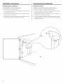
Mounting System Installation
Mounting Sgstem to Screws Installed in Wall
1. Removeshrink wrap from filter system.
2. Hang the system on the previously installed screws using the openings
on the back of the unit (Fig.7).
3. If the head of the screw will not slide into the upper slot, back out the
screw by i/4 turn and try again.
4. If the system istoo loosewhen placed on the wall,tighten the screws
by !//4 turn and try again until a desiredfit isachieved.
instrucciones deinstalaci6n.
Montaje de!sistema
Mantaje del sistema a los tarnillas instaladas en la pared
1. Remueva la envoltura de pliegue del sistema delfiltro.
2. Cuelgueel sistema en los tornillos previamente instalados usando las
aberturas en la parte posterior de la unidad (Fig.7).
3. Sila cabeza de lostornillos no se deslizanen las ranuras superiores,
destornille !//4 de vuelta y trate de nuevo.
4. Siel sistema estcidemasiado flojo cuando sea colocado en lapared,
apriete los tornillos !//4 de vuelta y trate de nuevo hasta que el ajuste
apropiado sea Iogrado.
5inches/
MJn.
17inches/
17pulgadas
Fig. 7
72

Installation Instructions.
Installing the Tubing
1. Measure 3/4" from the end of each remaining piece of tubing (faucet
end and inletend) and mark with a pencil (Fig.8).(Checkfor roundness,
smoothness,cuts, nicks,flat spots and sharp edges.)
3/4"---_-
19mm
INCORRECT
Fig. 8
2. NOTE:Water flow is from left to right. Water inlet is on the left side
and water outlet is on the right side. Failure to follow will result in
water leaks when filter canisters are removed.
........................................,
Inletfromsupplyvalve_ _ Outlet
tofaucet
Pushthe tubing firmly into each fitting on the manifold until the lineis
flush with the fitting collar. (Ifthe tubing isremoved, re-cut the end,
measure,mark and re-insert).Tubing must befully insertedto avoid
leaks(Fig.9).(Toremove tubing, depress end hold white caller; pull
tubing out to remove.)
WhiteCollet(DONOTREMOVE)
I
Insertionline---_-i_ 3/4
i i
Engagement
4"(3/8"tubing) I
Fig. 9
4 Pullout slightly on tubing to ensure a good seal.
5. Install the other endof the tubing from the inlet sideof the manifold to
the feed water adapter.
NOTE:Inspect the ends of the tubing to be sure there are no
imperfections and that the end of the tubing iscut square. It may be
necessary to cut the tubing again.
instrucciones de instalaci6n.
C6mo instalar la tuberie
Midauna distanciade 3//4pulgadadesdeel extremo de cada pieza
restante detuberia (extremodelgrifo gextremo de la entrada) gmarque
con 16piz(Fig.8).(Revisequequede pareja,lisag que no tenga cortes,
hendiduras,puntos pianoso bordesfilosos).
19mm
INCORRECTO
Fig. 8
2. NOTA:El fluja de agua es de izquierda a derecha. La entrada delagua
est6 en el lado izquierdo g la salida en el lado derecho. No seguir
estas instrucciones podria resultar en fugas cuando los cartuchos de
los filtros sean removidos.
Entradade lav_lvula
desuministro
_]iL .......................................... _ J
Salidahacia
el grifo
Empuje latuberia firmemente hacia coda conexi6n en el recolector
hasta que latuberia est6 niveladocon elcollar. (Siseretira latuberia,
vuelva a cortar el extremo, mida, marque y vuelva a insertar).Latuberia
debeestar firmemente insertada para evitarfugas (Fig.9).(Pare retirar
la tuberia: Libere g sostenga la boquilla blanca; hale la tuberia hacia
fuero paro retirurJ
Boquillablanca ,_,l__J..,._
(NORETIRAR)---_-__/
Lineadeinsercbn_'_ 3/4"'_"
I
' Enganche i
3/4" ---_
tuberiade3/8') I
Fig. 9
4 Saque la tuberia ligeramente para asegurar un buen sellamiento.
S. Instaleel otro extremo de latuberia desde el ladode laentrada del
recolector al adaptador de suministro de agua.
NOTA:Inspeccione los extremos del tubo para asegurarse que no
haya imperfecciones y que el extremo de la tuberia se haya cortado
perpendicularmente. Esposible que se necesite volver a cortar
la tuberia.
J3

Installation Instructions.
Battery Installation
Usea small flat bladescrewdriver or cointo remove the battery trag (A)
at the sideof the faucet base.
1,
Z Install oneCR2032,3 volt battery (B)+ sidedown into the battery traU
(A)(Fig.i0).
3. SlidetraL! into faucet base (C)until the battery traU(A)edge isflush with
the side of the base.
4. Theblue light (D)will flash Stimes, indicating a proper installation and
system reset.
5. NormallUthe light isoff. After 6 months of use,the light will flash again
every 30 seconds, indicating the proper time to replace the filter
canister.
NOTE:Theblue light ma_lstop blinking if it is allowed to blinkfor an
extended periodof time. To ensureproper operation,the battery should be
replacedwith everyfilter change.
instrucciones de instalaci6n.
Instalaci6n de la bateria
1. Use un destornillador de pala plana pequeBo o una moneda para
retirar la bandeja de la bateria (A)en el costado de labase del grifo.
2. Instale una bateria CR2032de 3voltios (B)con el lado positivo hacia
abajo en la bandeja (A)(Fig.10).
3. Deslicela bandeja en la base delgrifo (C)hasta que el borde de la
bandeja de la bateria (A)est6 nivelado con el costado de labase.
4. La luzazul (D)seiluminar6 de manera intermitente S veces,indicando
una instalaci6n correcta g la reinicializaci6ndel sistema.
S. Normalmente la luzest6 apagada. Despu6sde 6 mesesde uso,
la luz seencender6 de manera intermitente nuevamente cada 30
segundos, indicando quees elmomento de reemplazar el filtro.
NOTA:La luzazulpuede dejar de encendersesise deja pot un periodo de
tiempo prolongado. Para verificar laoperacidn cormcta, sedebecambiar la
bateria con cada cambio de filtro.
(D)Bluelight/ Luzazul
"""'IV_ _ p'J¢/ (B)Battery / Bateria
(C) Faucet base / _-'<'_-__ + 0/ (A) Battery tray
Basedelgrifo / Bandejadelabateria
Fig.10
14

Installation Instructions.
Replacing the Filter Canisters
Theblue light in the faucetbase will flashevery 30seconds to indicate a
filter change is needed. This occurs every 6months.
1. Removethe filter canisters from the manifold by rotating the canisters
to the left about 1/3 turn (Fig.11).NOTE:Asmall amount of water from
the tubing between the filter and the faucet may comeout. A small towel
should beable to catch it.
2. Removefoil on top of new replacement filter canisters. Installthe new
canisters into the manifold by turning to the right about 1/3 turn until
the alignment marks line up and the filter stops.DO NOT
OVERTIGHTENThefilter will rise up as it isturned.
& Turn handle on faucet to allow trapped air to purge from the system.
NOTE:System may make noise during this procedure.
4. Check for water leaks around the sgstem.
5. Once water starts to flow out of the faucet, allow the sgstem to run for
5 minutes to flush out ang harmless carbon fines that meg be present.
6. Turn off faucet and check around sgstem for leaks.
7. Removebattery tray and replace battery to resettimer. (SeeBattery
Installation for proper procedure).
Fig.11
To remove
Replacement Filter Canisters/Estimated Replacement Costs
FQSLF-Replacement filter canister $30-35
FQSVF--Replacementfilter canister$35-/40
Forreplacement parts,call toll4ree 800.626.2002.
Flush Procedure
Whenever water of unknown quality ispassed through the GEWater
Filtration system, the filter canisters should bediscarded and the filtration
system flushed.
WARNING: thesesustemsshouldonly beusedon
microbiologically safe wate_
Circumstances that may require flushing the system are:
* Boilwater advisorg
* Flooding of the GE Water Filtration sgstem
* Long-term non-use
Theprocedure for flushing the GEWater Filtration system is:
I. See Replacing the FilterCanisters section and follow steps 1-4.
Instruccionesde instalaci6n.
C6mo reemplazar los cartuchos de los filtros
Lo luz ozul en Io bose del grifo se encender_ de formo intermitente cede
30 segundos pore indicor qua es necesorio combior el filtro. Esto ocurre
cede 6 meses.
I. Retireloscartuchosde losfiltros del recolector girando los cartuchos
hacia la izquierda 1/3 de giro.(Fig.11).NOTA:Podr[asotir una pequeha
cantidad de agua de tatuberia entreetfiltro y el grifo, tacuat sepuede
absorber conuna toatta pequeha.
2. Retireelaluminio dela porte superiorde loscartuchosde repuestos.Instole
losnuevoscartuchosenel recolectorgirhndoloshacioIoderechaolrededor
de 1/3 degiro hostoque losmorcas deolineoci6nquedenen lineoy elfiltro
pare.NOAPRIETEENENCESO.Elfiltro podrio levontorseomedido que
segiro.
3. GireIo monijo en el grifo poro permitir que eloire otropodo sepurgue
delsistemo.
NOTA:Es posible que el sistema haga ruido durante este procedimiento.
4. Busque fugas de agua alrededor del sistema.
5. Una vez que el ague empiece a fluir del grifo, deje que el sistema opera
par 5 minutes pare expulsar cualquier traza de carbono que pueda
ester presente.
6. Cierre el grifo g revise alrededor del sistema en busca de fugas.
7. Retire la bandeja de la bateria g vuelva a instalar la bateria pare
inicializar el temporizador. (Vea la instalaci6n de la bateria pare
el procedimiento correcto).
Fig. 11
i /_Para_!i__4_ Para
ins]_arj -" i l '- retirar
Repuestosde los cartuchos del filtros/Costos estimados de reposici6n
FQSLF--Repuestodelcartucho delfiltro $30-35
FQVSF--Repuestodelcartucho delfiltro $35-40
Pararepuestos,Ilamegratis a1800.626.2002(EEUU.).
Procedimiento pare laver
Cada vez que ague de calidad desconocida es pasada a trav6s del
sistema de filtraci6n de agua GE, los cartuchos de los filtros deberian
ser deshechados g el sistema de filtraci6n lavado.
AD VERTENCIA: Estossistemassolamentedeberianusarse
en ague microbiol6gicamente segura.
Los circunstancias qua podrian requerir el lavado del sistema son:
* Advertencia de que hog que hervir el aguo
Inundaci6n del sistema de filtraci6n de agua GE
Largotiempo sin ser usado
Elprocedimiento pare laver el sistema de filtraci6n de ague GEes:
I. Vea la secci6n C6moreemplazar loscartuchos delos filtros g siga los
pasos 1-4.
15

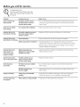
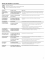
Before gou call for service...
Troubleshooting Tips
Save time and moneg! Review the chart
below first and gou mag not need to call
for service.
Problem Possible Causes What To Do
Water contains ring New filter canisters contain • Turn on the filtered water faucet and allow these harmless carbon
black particles activated carbon,which isa particlesto purge from the canisters.Turn off the faucet when the
harmless black powder, water isclear.
Water has air bubbles Air in sgstem after installation. •Will go awau after water runsfor a while.
and is cloudg
Indicator light on the Sixmonths usage has occurred. • Replaceboth filter canisters and battery in the faucet base.
faucet base is flashing This isthe maximum life of
the filter canisters.
Indicator light on the Normal operation. • Doesnot blinkuntil 6 months of operation haspassed.
faucet baseis not blinking
Batterg mag need to be replaced. • Normalluthe light isnot on.The light blinks everuSOsecondsto
indicate a filter change isneeded.This occurs about every 6 months.
Replacebattery. Indicator light will blinkrapidly 5 times to indicate
proper installation and operation.
Indicator light on the
faucet base is not
working when new
batterg is installed
Batterg mag need to be
replaced or it mag have been
installed incorrectlg.
Observeorientation markings on the holder and install correctly.
Replacebattery if it isold.
Chlorine taste and/or The filter canisters are no
odor in the product water longer removing chlorine
from the water supplg.
• Replace the filter canisters.
Water dispenses The filtershave been installed •A six-month change-out period isrecommended. Replaceboth
verg slowlg for too long. filter canisters.
The filter canisters have • Highsediment levelscan cause premature clogging. Replaceboth
become clogged, filter canisters.
Fittings are leaking Tubing mag not be installed • Fullyfollow the installation instructions and besure the tubing is
properlg, free of nicks,burrs, etc.,and isinstalled to the proper depth.
No water dispensing Filter canisters not fullg installed. • Fullyfollow the filter replacement instructions.
from sgstem
/6

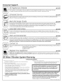
Antes de solicitar un servicio...
Solucionar problemas
iAhorre tiempo g dinero! Revise la siguiente tabla primero
bltol vez no necesitord de solicitor un servicio.
Problema Posibles causas Qu6 hacer
Elagua cantiene Losnuevos cartuchos de los filtros • Abra el grifo de agua filtrada g permita que estaspartfculas inofensivas
pequeflas particulas contienen carbono activado, el cual de carbono sepurguen de loscartuchos. Cierreel grifo cuando elagua
negras es un polvo negro inofensivo, salga limpia.
Elagua tiene burbujas Hag aire en el sistema despu_s • Desaparecer6despu6s de que el agua corra por untiempo.
de aire g est6 turbia de la instalaci6n.
La luz indicadara Han transcurrido seis meses • Reemplaceloscartuchos de losfiltros g la baterfa en la base
en la base delgrifo de uso. Estaes la vida m6xima delgrifo.
est6 intermitente de los cartuchosde losfiltros.
La luz indicadora Esto es normal. • No parpadea hasta que 6 meses de operaci6n han transcurrido.
en la base del grifo
no est6 intermitente. Esposible que la baterJa • Normalmente la luzno est6 encendida. La Iuzseenciende de manera
necesite reemplazo, intermitente para indicar que esnecesario cambiar elfiltro. Esto
ocurre coda seismeses.
• Reemplacela baterfa.La luzindicadora seencendercirapidamente
5 vecespara indicar la instalaci6n g operaci6n correcta.
La luz indicadara
en la base delgrifa
no funciana cuando se
instala una nueva batefia
La baterJa podria necesitar
reemplazo o podrJahaberse
instalado incorrectamente.
• Observelas marcas de orientaci6n en el receptciculoe instale
correctamente. Reemplacela baterfasi est6vieja.
Olor y/o sabor a cloro
en el agua producida
Los cartuchos de los filtms ga
no est_n retimndo el cloro del
suministm de agua.
• Reemplaceloscartuchos de losfiltros.
Elagua se dispensa
mug lentamente
Elfiltro ha estado instalado
por mucho tiempo.
• Serecomienda un periodo de cambio de seismeses.Reemplace
loscartuchos de losfiltros.
Loscartuchos de losfiltms
est_n obstruidos.
•Altos nivelesde sedimento pueden causar una obstrucci6n
prematura. Reemplaceloscartuchos de losfiltros.
Los accesorios
tienen fugas
Esposible que latuberJa • Sigalasinstrucciones de instalaci6n en sutotalidad g asegOrese
no est_ instalada correctamente, qua la tuberfa no posearasguhos,rebabas, etc.g que est_
instalada a una profundidad adecuada.
No sale agua
del sistema
Loscartuchosde losfiltros no • Sigacompletamente lasinstrucciones para reemplazo.
est_n instalados completamentes.
J7

Notes./Notos.
18

Soporte
l
,J
a! consumidor.
Pdgina Web de GE www.GEAppliances.com
LTienealguna pregunta sobre su electrodom@stico?iPruebe la p6ginaWeb de GE24 horas al dia, cualquier dia del ari!! Para magor
convenienciag serviciom6s r6pido,ga puede descargar losManuales de los Propietarioso pedir piezas en linea.
Solidte unareparaci6n www.GEAppliances.corn
Elserviciode e×pertosGEest6 a tan s61oun paso de su puerta, klame a1800.GECARES(800.452.2757)durante horas normales
deoficinaparasolicitarsureparaci6n.
RealLifeDesignStudio(EstudiodediseYToparalavidareal)wwwoGEAppliances.corn
GEapogaelconceptodeDiseroUniversal-productos,serviciosg ambientesque puedenusargentedetodaslasedades,tamaros
gcapacidades.Reconocemosla necesidaddediserarparaunagrangamadehabilidadesg dificultadesfisicasgmentales.Paramas
detallescobrelasaplicacionesdeGEDiseroUniversal,inclugendoideasdediseroparalacocinaparapersonascondiscapacidades,mire
nuestrap6ginaWebhogmismo.Parapersonascondificultadesauditivas,favordeIlamara1800.TDD.GEAC(800.855.4522).
Garantiasampliadas www.GEAppliances.carn
Compreunagarantiaampliadagobtengadetallessobredescuentosespecialesdisponiblesmientrassugarantiaest6a0nactiva.Puede
comprarlaenlineaencualquiermomenta,o Ilamaral(800.626.2224)durantehorasnormalesdeoficina.GEConsumerHomeServices
estar6a0nahicuandosugarantiatermine.
Piezas g accesorios www.GEAppliances.corn
Aquellosindividuosconla calificaci6nnecesariapararepararsuspropioselectrodom@sticospuedenpedirqueselesmanden
laspiezaso accesoriosdirectamentea sushogares(aceptamoslastarjetasVISA,MasterCardg Discover).Hagasupedidoenlineahog,
24horascadadiao Ilamarporteldonoa1800.626.2002durantehorasnormalesdeoficina.
Lasinstruccionesdescritasenestemanualcubrenlosprocedimientosaseguirporcualquierusuario.Cualquierotrareparaci6ndeberia,porreglageneral,
referirseapersonalcalificadoautorizado.Debeejercerseprecauci6ngaque/asreparacionesincorrectaspuedencausarcondicionesdefuncionamiento
_bg uras"
ngose en contocto con nosotros www.GEAppliances.carn
Sinoest6satisfechoconelservicioquerecibedeGE,p6ngaseencontactoconnosotrosennuestrap6ginaWebindicandotodoslos
detallesasicomosunOmerodeteldonoo escribanosa: GeneralManager,CustomerRelations
GEAppliances,AppliancePark
Louisville,KV40225
Registresu electrodomdstico www.GEAppliances.corn
iRegistresunuevoelectrodom_sticoen linea-cuando ustedprefiera!Elregistrarsuproductoatiempoleproporcionar6,sisurgierala
necesidad,unamejorcomunicaci6ngun serviciomasr6pidobajolost@minosdesugarantia.Tambi6npuedeenviarsutarjeta
deregistropre-impresaqueseinclugeenel materialdeembalaje.
Garantia del sistema de filtraci6n de agua GE.
GARANTiA LIMITADA POR UN ANO
• _Qud cubre esta garantia?
- Cualquier defecto de f6brica en los materiales o la manufactura del producto.
• LQud no cubre esta garantia?
- Cortuchodelosfiltros g lasbaterfasdespu6sdetreinto dfaso partir delafecha dela compra.
- Viajes a su casa para enseflarle c6mo usar el producto.
- Instalaci6n o entrega inapropiada, o mantenimiento impropio.
- Palladel producto debido a abuso, mal uso, alteraci6n, uso comercial o uso diferente al
prop6sito deseado con este producto.
- Uso de este producto donde el agua est6 microbiol6gicamente insegura o de calidad
desconocida, sin la adecuada desinfecci6n, antes g despu@sde ser procesada por el
sistema. Lossistemas certificados para reducir el nivelde quistes pueden ser usados
en agua desinfectada que pueda contener quistes que se puedan filtra_
- Dafios causados al producto debido a accidentes, incendio, inundaciones o actos
de la naturaleza.
-- Da_os secundarios o por consecuencia causados por posibles defectos en el
producto, su instalaci6n o reparaci6n.
• _Por cudnto tiempo despu_s de la compra?
-- Un aflo.
• _C6mo hago la reclamaci6n de la garantia?
- Devu61valaal rninorista a quienle cornpr6 elproducto conuna copia de "Proof of
Purchase"(pruebadecornpra).Seleproporcionar6 una unidad nueva o reacondicionada. Esta
garantia excluge los costosde envio o Ilarnadas de servicioa dornicilio.
EXCLUSI6N DE GARANT[AS IPIPL[CITAS--Su _nico g exclusivo derecho es el
cambio del producto, tal g como se indica en esta Garantia limitada.
Cualquier garantia implicita, inclugendo los garantias implicitas de
comerciabilidad o adecuaci6n para un fin determinado, est6n limitadas a
un afio o el periodo de tiempo m6s breve permitido por la leg.
Esta garantia se extiende al comprador original gcualquier comprador
posterior de productos comprados para uso residencial o en la oficina dentro de
Estados Unidos. EnAlaska, la garantia excluge el costo de envio o las visitas de
servicio a su casa u oficina.
Algunos estados no permiten la exclusi6n o las limitaciones de da_os
incidentales o consecuenciales. Esta garantia da derechos legales especificos, g
usted podria tener otros derechos que variar6n de estado a estado. Para saber
cuOlesson sus derechos legales, consulte a la oficina de asuntos del
consumidor local o la oficina del Attomeg General en su Iocalidad.
P6ngase en contacto con nosotros en ge.com, o Ilame sin cargo a1800.9S2.S039.
lmpreso en Estados Unidos 19

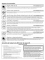
Consumer Support.
GEAppliances Website
Havea questionor needassistancewithyourappliance?TrytheGEAppliancesWebsite24hoursaday,anydayoftheyear!
Forgreaterconvenienceandfasterservice,youcannowdownloadOwner'sManualsor orderpartson-line.
ge.com
Schedule Service ge.com
ExpertGErepair serviceisonly one step away from yourdoor.Schedule yourserviceat your convenience by calling800.GECARES
(800./452.2757)duringnormal business hours.
]
RealLifeDesignStudio
ge.com
GEsupportstheUniversalDesignconcept-products,servicesandenvironmentsthat canbe usedbypeopleofallages,sizes
andcapabilities.Werecognizetheneedtodesignfora widerangeofphysicalandmentalabilitiesandimpairments.Fordetails
ofGE'sUniversalDesignapplications,includingkitchendesignideasforpeoplewithdisabilities,checkoutour Websitetoday.
Forthe hearingimpaired,pleasecall800.TDD.GEAC(800.833.4322).
Extended Warranties
ge.com
Purchasea GEextendedwarrantyandlearnaboutspecialdiscountsthatareavailablewhileyourwarrantyisstillineffect.Youcan
purchaseiton-lineanytime,orcall800.626.2224duringnormalbusinesshours.GEConsumerHomeServiceswillstillbethereafteryour
warrantyexpires.
Parts and Accessories
ge.com
Individualsqualifiedto servicetheirownappliancescanhavepartsor accessoriessentdirectlytotheirhomes(VISA,MasterCardand
Discovercardsareaccepted).Orderon-linetoday,24hourseverydayorby phoneat 800.626.2002duringnormalbusinesshours.
Instructionscontainedin thismanualcoverprocedurestobeperformedby any user.Otherservicinggenera@shouldbereferredto
qualifiedservicepersonnelCautionmustbeexercised,sinceimproperservicingmaycauseunsafeoperation.
Contact Us
ge.com
If youarenotsatisfiedwiththeserviceyoureceivefromGE,contactusonourWebsitewithallthedetailsincludingyourphonenumber,or
writeto: GeneralManager,CustomerRelations
GEAppliances,AppliancePark
Louisville,KY40225
RegisterYourAppliance
ge.com
Registeryour newapplianceon-line-at yourconvenience!Timelyproductregistrationwillallowforenhancedcommunicationand
promptserviceunderthetermsof yourwarranty,shouldtheneedarise.Youmayalsomailinthe preprintedregistrationcardincludedin
thepackingmaterial.
GE Water Filtration Sgstem Warrantg.
LIMITED ONE-YEAR WARRANTY
• What doesthis warranty cover?
- Any defect in materials or workmanship in the manufactured product.
• What doesthis warranty not cover?
- Filter canisters and batteries after 30 dags from date of purchase.
- Servicetrips to your home to teach you how to use the product.
- Improper installation, delivery or maintenance.
- Failure of the product if itis abused, misused,altered, used commercially or
used for other than the intended purpose.
- Use of this product where water is microbiologicallg unsafe or of unknown
quality, without adequate disinfection before or after the system. Systems
certified for cyst reduction may be used on disinfected water that may
contain filterable cysts.
- Damage to the product caused bg accident, fire,floods or acts of God.
- Incidental or consequential damage caused bg possible defects with this
appliance, its installation or repair.
• Forhow tong after the original purchase?
--One (i)yea_
• How do I make a warranty claim?
--Returnto the retailer from which it was purchased, along with a copy of the
"Proof of Purchase."A new or reconditioned unit will be provided.This
warrant 9 excludesthe cost of shipping or service callsto your home.
EXCLUSIONOFIMPLIEDWARRANTIES--Yoursole and exclusive remedy is
product exchangeas provided in this Limited Warranty. Any implied
warranties, including the implied warranties of merchantabilitg orfitness
for a particular purpose, are limited to one year or the shortest period
allowed by law.
This warrantg is extended to the original purchaser and ang succeeding owner
for products purchased for home or office use within the USA.In Alaska, the
warrantg excludes the cost of shipping or service to gour home or office.
Some states donot allow the exclusion or limitation of incidental or consequential
damages. Thiswarrantg gives gouspecific legalrights, and gou mag alsohave other
rights, which varg from state to state. To knowwhat gour legal rights are,consult
gour local or state consumer affairs officeor gour state's Attomeg General.
Contact us at ge.com, or calltoll-free at 800.952.5039.
Printed in the United States
-
 1
1
-
 2
2
-
 3
3
-
 4
4
-
 5
5
-
 6
6
-
 7
7
-
 8
8
-
 9
9
-
 10
10
-
 11
11
-
 12
12
-
 13
13
-
 14
14
-
 15
15
-
 16
16
-
 17
17
-
 18
18
-
 19
19
-
 20
20


GE GXSV65R00 El manual del propietario
- Tipo
- El manual del propietario
- Este manual también es adecuado para
en otros idiomas
- English: GE GXSV65R00 Owner's manual
Artículos relacionados
-
GE GX1S50R00 El manual del propietario
-
-
-
-
-
-
-
-
-
 GE Appliances GXK185KBL El manual del propietario