Yamaha RX-A2020 Guía de instalación

Categoría
Receptores AV
Tipo
Guía de instalación

Este manual también es adecuado para

English
Español
Easy Setup Guide
Guía de configuración sencilla
AV Receiver/Receptor AV
RL
RX-A3020_2020_esg_RLH_cover1.fm Page 1 Wednesday, May 2, 2012 1:47 PM
Black process 45.0° 240.0 LPI
En 1
Check that the following accessories are supplied with the product.
The following cables (not supplied) are required to build the system described in this
document.
Speaker cables (x9)
HDMI cable (x2)
Audio pin cable (x1)
Digital optical cable or stereo pin cable (x1*)
* Not required if your TV supports ARC (Audio Return Channel)
1 Preparation
Accessories
Remote control Batteries (x4)
Insert the batteries the right way round.
AM antenna FM antenna YPAO microphone
Microphone base
(RX-A3020 only)
Power cable
CD-ROM
(Owner’s Manual)
Safety Brochure
Easy Setup Guide
The illustrations of the main unit and remote control used in this guide are of the RX-A3020 (U.S.A.
model), unless otherwise specified.
*RX-A3020: AAA, LR03, UM-4
RX-A2020: AAA, R03, UM-4
*One of the above is supplied depending
on the region of purchase.
*One of the above is supplied depending
on the region of purchase.
*The supplied power
cable varies
depending on the
region of purchase.
*Using for angle
measurement
during YPAO.
Cables required for connections
UAB
This document explains how to set up a 9.1-channel system and play
back surround sound from a BD/DVD on the unit.
To reduce the impact on natural resources, the Owner’s Manual for this product is
supplied on CD-ROM. For more information about this product, refer to the
Owners Manual on the supplied CD-ROM.
PDF versions of this guide and “Owners Manual” can be downloaded from the
following website.
http://download.yamaha.com/
Easy Setup Guide
English
AV Receiver
RX-A3020_2020_esg_body_C.fm Page 1 Wednesday, May 2, 2012 1:58 PM
Black process 45.0° 240.0 LPI
2 En
Set up the speakers in the room using the following diagram as a reference.
For information on speaker systems other than 9.1-channel system, refer to “Owner’s Manual”.
2 Placing speakers
ER
12
39
45
67
10° to 30°10° to 30°
1 Front speaker (L)
2 Front speaker (R)
3 Center speaker
4 Surround speaker (L)
5 Surround speaker (R)
6 Surround back speaker (L)
7 Surround back speaker (R)
E Front presence speaker (L)
R Front presence speaker (R)
9 Subwoofer
1.8 m
(5.9 ft)
0.5 to 1 m
(1.6 to 3.3 ft)
1.8 m
(5.9 ft)
0.3 m (1 ft) or more
0.5 to 1 m
(1.6 to 3.3 ft)
RX-A3020_2020_esg_body_C.fm Page 2 Wednesday, May 2, 2012 1:58 PM
Black process 45.0° 240.0 LPI
En 3
Connecting speaker cables
Speaker cables have two wires. One is for connecting the
negative (–) terminals of the unit and the speaker, and the
other is for the positive (+) terminals. If the wires are
colored to prevent confusion, connect the black wire to
the negative and the other wire to the positive terminals.
a Remove approximately 10
mm (3/8”) of insulation
from the ends of the
speaker cable and twist
the bare wires of the cable
firmly together.
b Loosen the speaker terminal.
c Insert the bare wires of the cable into the gap on the side
(upper right or bottom left) of the terminal.
d Tighten the terminal.
Using a banana plug
(U.S.A., Canada, China,
Australia and General
models only)
a Tighten the speaker
terminal.
b Insert a banana plug into the end of the terminal.
1
Connect the front speakers (1/2)
to the FRONT (//\) and the center
speaker (3) to the CENTER terminal.
2
Connect the surround speakers
(4/5) to the SURROUND (//\)
terminals.
3 Connecting speakers/subwoofer
Under its default settings, the unit is configured for 8-ohm
speakers. When connecting 6-ohm speakers, set the unit’s
speaker impedance to “6 Ω MIN”. For details, see “Setting the
speaker impedance” in “Owner’s Manual”.
Use a subwoofer equipped with built-in amplifier.
Before connecting the speakers, remove the unit’s power cable
from the AC wall outlet and turn off the subwoofer.
Ensure that the core wires of the speaker cable do not touch
each other or come into contact with the unit’s metal areas. This
may damage the unit or the speakers. If the speaker cables
short circuit, “Check SP Wires” will appear on the front display
when the unit is turned on.
FRONT
-
+
aa
b
d
c
– (black)
+ (red)
FRONT
+
a
b
1
2
ZONE OUT/PRE OUT
CENTER
SUBWOOFER
ZONE 2 /
F.PRESENSE
ZONE 3 /
R.PRESENSE
FRONT
SURROUND SUR. BACK
SPEAKERS
CENTER FRONT
SURROUND BACKSURROUND
BI–AMP
ZONE 2/ZONE 3/F.PRESENCE/
ZONE 2/ZONE 3/R.PRESENCE
R L
R L
R
R
R
L
L
L
SINGLE
PRE OUT
SUBWOOFER
CENTER
FRONT
SURROUND SUR. BACK
(SINGLE) (FRONT)
(REAR)
EXTRA SP1
EXTRA SP2
12
3
45
9
ER
67
The unit (rear)
RX-A3020_2020_esg_body_C.fm Page 3 Wednesday, May 2, 2012 1:58 PM
Black process 45.0° 240.0 LPI
4 En
3
Connect the surround back speakers
(6/7) to the SURROUND BACK
(//\) terminals.
4
Connect the front presence speakers
(E/R) to the EXTRA SP 1 (//\)
terminals.
5
Connect the subwoofer (9) to the
SUBWOOFER (1) jack.
1
2
ZONE OUT/PRE OUT
CENTER
SUBWOOFER
ZONE 2 /
F.PRESENSE
ZONE 3 /
R.PRESENSE
FRONT
SURROUND SUR. BACK
SPEAKERS
CENTER FRONT
SURROUND BACKSURROUND
BI–AMP
ZONE 2/ZONE 3/F.PRESENCE/
ZONE 2/ZONE 3/R.PRESENCE
R L
R L
R
R
R
L
L
L
SINGLE
PRE OUT
SUBWOOFER
CENTER
FRONT
SURROUND SUR. BACK
(SINGLE) (FRONT)
(REAR)
EXTRA SP1
EXTRA SP2
12
3
45
9
ER
67
The unit (rear)
1
2
ZONE OUT/PRE OUT
CENTER
SUBWOOFER
ZONE 2 /
F.PRESENSE
ZONE 3 /
R.PRESENSE
FRONT
SURROUND SUR. BACK
SPEAKERS
CENTER FRONT
SURROUND BACKSURROUND
BI–AMP
ZONE 2/ZONE 3/F.PRESENCE/
ZONE 2/ZONE 3/R.PRESENCE
R L
R L
R
R
R
L
L
L
SINGLE
PRE OUT
SUBWOOFER
CENTER
FRONT
SURROUND SUR. BACK
(SINGLE) (FRONT)
(REAR)
EXTRA SP1
EXTRA SP2
12
3
45
9
ER
67
Audio pin cable
The unit (rear)
RX-A3020_2020_esg_body_C.fm Page 4 Wednesday, May 2, 2012 1:58 PM
Black process 45.0° 240.0 LPI
En 5
4 Connecting external devices
INPUT
MAIN ZONE
VOLUME
PURE DIRECT
NETWORKDC OUT
5V
0.5A
( 3
NET
)
MONITOR OUT/
ZONE OUT
HDMI OUT
ARC
(ZONE OUT)
12
HDMI
(1 BD/DVD)
AV 1 AV 2 AV 3 AV 4 AV 5 AV 6 AV 7
TRIGGER
OUT
1
2
RS-232C
YPB PR
YPB PR
YPB PR
MONITOR OUT/ZONE OUT
IN OUT IN OUT
AV 1
AV 3
REMOTE
12
COMPONENT VIDEO
A
AV 2
B
C
AV 4
D
AV OUT
R
L
AV 3 AV 4AV 2AV 1
(1 BD/DVD)
OPTICAL
4
OPTICAL
3
COAXIAL
2
COAXIAL
1
PHONO
GND
AC IN
OPTICAL
1
2
AUDI O 4
MULTI CH INPUT
ZONE OUT/PRE OUT
AUDIO 3AUDI O 2AUDIO 1
(2 TV)
CENTER
SUBWOOFER
ZONE 2 /
F.PRESENSE
ZONE 3 /
R.PRESENSE
FRONT
SURROUND SUR. BACK
SPEAKERS
CENTER FRONT
SURROUND BACKSURROUND
BI–AMP
ZONE 2/ZONE 3/F.PRESENCE/
ZONE 2/ZONE 3/R.PRESENCE
R
5
COAXIAL
6
L
R L
R
R
R
L
L
L
SINGLE
PRE OUT
SUBWOOFER
CENTER
FRONT
SURROUND SUR. BACK
(SINGLE) (FRONT)
(REAR)
EXTRA SP1
EXTRA SP2
12V 0.1A
FM
75Ω
ANTENNA
HD Radio
AM
(4 RADIO)
(1 BD/DVD)
AV 1
HDMI OUT
ARC (ZONE OUT)
12
L
R
OPTICAL
HDMI
HDMI
OPTICAL
AUDIO 1
(2 TV)
5
VOLTAGE SELECTOR
220V-
240V
110V-
120V
L
R
L
R
O
O
HDMI
HDMI
HDMI
a
d
c
HDMI
b
TVAudio out (digital optical or
analog stereo)
HDMI in HDMI out
BD/DVD player
HDMI OUT 1
jack
HDMI (AV 1) jack
AUDIO 1
(OPTICAL or AUDIO) jack
The unit (rear)
To an AC wall
outlet
Turn on the unit
The unit (front)
VOLTAGE SELECTOR
(General model only)
Press the bottom of the
front panel door gently to open the door
1
Connect external devices to the unit.
a Connect a BD/DVD player to the unit with an HDMI
cable.
If the BD/DVD player is currently connected to the
TV directly with an HDMI cable, disconnect the
cable from the TV and connect it to the unit.
b Connect a TV to the unit with the other HDMI cable.
c Connect a TV to the unit with a digital optical cable
or a stereo pin cable.
This connection is required to play back TV audio
on the unit. This connection is not required if your
TV supports ARC (Audio Return Channel).
d Connect the supplied power cable to the unit and
then to an AC wall outlet.
For information on how to connect radio antennas or other
external devices, see “PREPARATIONS” in “Owner’s Manual”.
2
Turn on the unit, the TV and the BD/DVD
player.
3
Use the TV remote control to change the
TV input to video from the unit.
The connections are complete. Proceed to the next
page to optimize the speaker settings.
You can select the on-screen menu language from English (default),
Japanese, French, German, Spanish, Russian and Chinese. For
details, refer to “Owner’s Manual”. In this guide, illustrations of
English menu screens are used as examples.
Before connecting the power cable (General model only)
Make sure you set the switch position of
VOLTAGE SELECTOR according to your local voltage.
Voltages are AC 110-120/220-240 V, 50/60 Hz.
RX-A3020_2020_esg_body_C.fm Page 5 Wednesday, May 2, 2012 1:58 PM
Black process 45.0° 240.0 LPI
6 En
The Yamaha Parametric room Acoustic Optimizer (YPAO) function detects speaker connections, measures the
distances from them to your listening position(s), and then automatically optimizes the speaker settings, such as
volume balance and acoustic parameters, to suit your room.
Preparing for YPAO
5
Optimizing the speaker settings automatically (YPAO)
SOURCE
RECEIVER
AV
AUDIO
1 2 3 4
5 6 7
V-A UX
1 2 3 4
MULTI
PHONO
USB NET
TUNER
[ C ][ A ] [ B ]
CLASSICAL
LIVE
CLUB
ENTERTAIN
MOVIE
STEREO STRAIGHT
INPU
T
PURE
DIRECT
MUTE
TV
SCENE
1 2 3 4
PROGRAM
VOLUME
TV VOL
MUTE
MODE
TO
P MENU
RETURN DISPLAY
POP-UP/MEN
U
TV CH
PRESET
ENTER
ON SCREEN
OPTION
SOU
R
CE
R
E
C
EIV
E
R
AV
A
UD
I
O
1
2
3
4
5
6
7
V-A
U
X
1
2
3
4
MUL
TI
L
L
PH
O
N
O
U
S
B
N
E
T
TUNE
R
[
C
]
[
A
]
[
B
]
Cursor keys
ENTER
RETURN
During the measuring process, test tones are output at high volume. Ensure that the test
tones do not frighten small children. Also, refrain from using this function at night when it
may be a nuisance to others.
During the measuring process, you cannot adjust the volume.
During the measuring process, keep the room as quiet as possible.
Do not connect headphones.
Do not stand between the speakers and the YPAO microphone during the measurement
process (about 3 minutes).
Move to the corner of the room or leave the room.
YPAO MIC
VOLUME HIGH CUT
CROSSOVER/
MIN MAXMIN MAX
The unit (front)
Place the YPAO microphone at your
listening position (same height as your
ears). We recommend the use of a
tripod as a microphone stand. You can
use the tripod screws to fix the
microphone in place. (The microphone
direction is not considered.)
YPAO
microphone
Ear height
Turn on the subwoofer and set
the volume to half. If the
cross-over frequency is
adjustable, set it to maximum.
1
Connect the YPAO microphone to the
YPAO MIC jack on the front panel.
The following screen appears on the TV.
To cancel the operation, disconnect the YPAO microphone
before starting the measurement.
2
To start the measurement, use the cursor
keys to select “Measure” and press
ENTER.
The measurement will start in 10 seconds.
The following screen appears on the TV when
the measurement finishes.
If any error message (such as E-1) or warning message (such
as W-2) appears, see “Error messages” or “Warning
messages” in “Owner’s Manual”.
If the warning message “W-1:Out of Phase” appears, see
“If “W-1:Out of Phase” appears” (next page).
RX-A3020_2020_esg_body_C.fm Page 6 Wednesday, May 2, 2012 1:58 PM
Black process 45.0° 240.0 LPI
En 7
3
Use the cursor keys to select
“Save/Cancel” and press ENTER.
4
Use the cursor keys to select “SAVE” and
press ENTER.
5
Disconnect the YPAO microphone from the
unit.
This completes optimization of the speaker settings.
Follow the procedure below to check the speaker
connections.
Depending on the type of speakers or room
environment, this message may appear even if the
speakers are connected correctly.
a Use the cursor keys to select “Result” and press ENTER.
b Use the cursor keys to select “Wiring”.
c Check the cable connections (+/–) of the speaker that
was identified as being “Reverse” in the warning
message.
If the speaker is connected correctly:
You can save the current settings.
Press RETURN and proceed to step 3.
If the speaker is connected incorrectly:
Turn off the unit, reconnect the speaker cable, and then
try YPAO measurement again.
The YPAO microphone is sensitive to heat, so should not be
placed anywhere where it could be exposed to direct sunlight or
high temperatures (such as on top of AV equipment).
If “W-1:Out of Phase” appears
RX-A3020_2020_esg_body_C.fm Page 7 Wednesday, May 2, 2012 1:58 PM
Black process 45.0° 240.0 LPI
8 En
Now let’s play back a BD/DVD.
We recommend playing back multichannel audio
(5.1-channel or more) to feel surround sound produced
by the unit.
1
Press AV 1 to select “AV 1” as the input
source.
2
Start playback on the BD/DVD player.
3
Press STRAIGHT repeatedly to select
“STRAIGHT”.
To check if sounds are properly heard from all speakers, press
STEREO repeatedly to select “9ch Stereo”.
4
Press VOLUME to adjust the volume.
This completes the basic setup procedure.
Sound is only being output from the front speakers
during multichannel audio playback
Check the digital audio output setting on the BD/DVD
player.
It may be set to 2-channel output (such as PCM).
No sound is coming from a specific speaker
See “Troubleshooting” in “Owner’s Manual”.
6 Playing back a BD/DVD
SOURCE
RECEIVER
AV
AUDIO
1 2 3 4
5 6 7
V-A UX
1 2 3 4
MULTI
PHONO
USB NET
TUNER
[ C ][ A ] [ B ]
CLASSICAL
LIVE
CLUB
ENTERTAIN
MOVIE
STEREO STRAIGHT
INPU
T
PURE
DIRECT
MUTE
TV
SCENE
1 2 3 4
PROGRAM
VOLUME
TV VOL
MUTE
MODE
TO
P MENU
RETURN DISPLAY
POP-UP/MEN
U
TV CH
PRESET
ENTER
ON SCREEN
OPTION
SOU
R
CE
R
E
C
EIV
E
R
AV
A
UD
I
O
2
3
4
5
6
7
V-A
U
X
1
2
3
4
MUL
TI
L
L
PH
O
N
O
U
S
B
N
E
T
TUNE
R
[
C
]
[
A
]
[
B
]
AV 1
STRAIGHT
STEREO
VOLUME
If surround sound is not working
OUT
1
IN
OUT
2
VOLUME
MUTE
DRCADAPTIVE
3
ZONE
2
STEREO
ENHANCER
SLEEP
HD
TUNED
PRE
AMP
PARTY
ZONE
3
ZONE
4
HD
TAG
DOCK
SBLPL SBRSB PR
SW1
SL
SW2SW
SR
PL
CLR
PR
A.Sel:Auto
AV1
SPIMP.-
VOLUME
SBL SBR
SW1
SL SR
CLR
STRAIGHT
VOLUME
SBL SBR
SW1
SL SR
CLR
Main:Volume
Many more features!
The unit has various other functions.
Please refer to “Owner’s Manual” on the supplied
CD-ROM to help you get the most out of the unit.
Connecting other playback
devices
Connect audio devices (such as CD player),
game consoles, camcorders, and many others.
Selecting the sound mode
Select the desired sound program (CINEMA
DSP) or surround decoder suitable for movies,
music, games, sports programs, and other uses.
Playing back from iPod
By using a USB cable supplied with iPod, you
can enjoy iPod music on the unit.
Listening to FM/AM radio
Playing back music stored on
a USB storage device
Playing back the network
contents
Selecting the input source and
favorite settings at once
For more information, see “What you can do
with the unit”.
RX-A3020_2020_esg_body_C.fm Page 8 Wednesday, May 2, 2012 1:58 PM
Black process 45.0° 240.0 LPI
Es 1
Compruebe que se suministran los siguientes accesorios con el producto.
Se necesitan los siguientes cables (no suministrados) para crear el sistema descrito en
este documento.
Cables de altavoz (x9)
Cable HDMI (x2)
Cable de audio con patillas (x1)
Cable óptico digital o cable con clavija estéreo (x1*)
* No es necesario si su TV es compatible con ARC (Audio Return Channel)
1 Preparación
Accesorios
Mando a distancia Pilas (x4)
Inserte las pilas en el sentido correcto.
Antena de AM Antena de FM Micrófono YPAO
Base del
micrófono
(solo
RX-A3020)
Cable de
alimentación
CD-ROM
(Manual
de instrucciones)
Folleto de
seguridad
Guía de
configuración
sencilla
Las ilustraciones de la unidad principal y del mando a distancia utilizadas en esta guía corresponden
al modelo RX-A3020 (modelo de Estados Unidos), a menos que se especifique de otro modo.
*RX-A3020: AAA, LR03, UM-4
RX-A2020: AAA, R03, UM-4
*Se suministra una de las indicadas
arriba, según la región en la que se
realice la compra.
*Se suministra una de las indicadas
arriba, según la región en la que se
realice la compra.
*El cable de
alimentación
suministrado varía
según la región en la
que se realice la
compra.
*Utilizado para la
medición de ángulo
durante YPAO.
Cables necesarios para las conexiones
UAB
En este documento se explica cómo configurar un sistema de 9.1
canales y reproducir el sonido surround de un BD/DVD en la unidad.
Para reducir el impacto en los recursos naturales, el Manual de’Instrucciones de
este producto se suministra en CD-ROM. Para obtener más información sobre el
producto, consulte el Manual de’Instrucciones que encontrará en el CD-ROM
suministrado.
Se pueden descargar versiones PDF de esta guía y el “Manual de Instrucciones”
desde el siguiente sitio web.
http://download.yamaha.com/
Guía de configuración
sencilla
Español
Receptor AV
RX-A3020_2020_esg_RL.fm Page 1 Wednesday, May 30, 2012 4:39 PM
2 Es
Instale los altavoces en la sala con ayuda del diagrama siguiente como referencia.
Para obtener información sobre otros sistemas de altavoces que no sean sistemas de 9.1 canales, consulte el “Manual de Instrucciones”.
2 Colocación de los altavoces
ER
12
39
45
67
De 10° a 30°De 10° a 30°
1 Altavoz delantero (Izq.)
2 Altavoz delantero (Der.)
3 Altavoz central
4 Altavoz surround (Izq.)
5 Altavoz surround (Der.)
6 Altavoz surround trasero (Izq.)
7 Altavoz surround trasero (Der.)
E Altavoz de presencia delantero (Izq.)
R Altavoz de presencia delantero (Der.)
9 Subgraves
1,8m
De 0,5 a 1 m
1,8m
0,3 m o más
De 0,5 a 1 m
RX-A3020_2020_esg_RL.fm Page 2 Wednesday, May 30, 2012 4:39 PM
Es 3
Conexión de los cables de los
altavoces
Los cables de los altavoces tienen dos hilos. Uno es
para conectar los terminales negativos (–) de la unidad
y el altavoz y el otro para los terminales positivos (+). Si
los hilos están codificados por colores para evitar
confusiones, conecte el hilo negro en los terminales
negativos y el otro hilo en los terminales positivos.
a Quite aproximadamente
10 mm de aislamiento de
los extremos del cable del
altavoz y retuerza los
hilos expuestos con
firmeza para juntarlos.
b Afloje el terminal de los
altavoces.
c Introduzca los hilos expuestos del cable en el hueco del
lado (superior derecho o inferior izquierdo) del terminal.
d Apriete el terminal.
Utilización de un conector
tipo banana
(Sólo modelos de EE. UU.,
Canadá, China, Australia
y general)
a Apriete el terminal de los
altavoces.
b Inserte un conector tipo banana en el extremo del terminal.
1
Conecte los altavoces delanteros
(1/2) a los terminales FRONT
(//\) y el altavoz central (3) al
terminal CENTER.
2
Conecte los altavoces surround
(4/5) a los terminales
SURROUND (//\).
3 Conexión de los altavoces y el subgraves
Según sus ajustes predeterminados, la unidad está configurada
para altavoces de 8 . Si conecta altavoces de 6 , ajuste la
impedancia de los altavoces de la unidad en “6 Ω MIN”. Para
conocer más detalles, consulte “Ajuste de la impedancia de los
altavoces” en el “Manual de Instrucciones”.
Utilice un subwoofer que disponga de un amplificador
incorporado.
Antes de conectar los altavoces, retire el cable de alimentación
de la unidad de la toma de CA y apague el altavoz de subgraves.
Asegúrese de que los hilos del núcleo del cable del altavoz no
se tocan entre sí o de que no entran en contacto con las zonas
metálicas de esta unidad. Esto puede dañar la unidad o los
altavoces. Si se produce un cortocircuito en los cables de los
altavoces, aparecerá “Check SP Wires” en el visor delantero
cuando se enciende la unidad.
FRONT
-
+
aa
b
d
c
– (negro)
+ (rojo)
FRONT
+
a
b
Conector tipo
banana
1
2
ZONE OUT/PRE OUT
CENTER
SUBWOOFER
ZONE 2 /
F.PRESENSE
ZONE 3 /
R.PRESENSE
FRONT
SURROUND SUR. BACK
SPEAKERS
CENTER FRONT
SURROUND BACKSURROUND
BI–AMP
ZONE 2/ZONE 3/F.PRESENCE/
ZONE 2/ZONE 3/R.PRESENCE
R L
R L
R
R
R
L
L
L
SINGLE
PRE OUT
SUBWOOFER
CENTER
FRONT
SURROUND SUR. BACK
(SINGLE) (FRONT)
(REAR)
EXTRA SP1
EXTRA SP2
12
3
45
9
ER
67
Unidad (parte trasera)
RX-A3020_2020_esg_RL.fm Page 3 Wednesday, May 30, 2012 4:39 PM
4 Es
3
Conecte los altavoces traseros surround
(6/7) a los terminales
SURROUND BACK (//\).
4
Conecte los altavoces de presencia
delanteros (E/R) a los terminales
EXTRA SP 1 (//\).
5
Conecte el altavoz de subgraves (9)
a la toma SUBWOOFER (1).
1
2
ZONE OUT/PRE OUT
CENTER
SUBWOOFER
ZONE 2 /
F.PRESENSE
ZONE 3 /
R.PRESENSE
FRONT
SURROUND SUR. BACK
SPEAKERS
CENTER FRONT
SURROUND BACKSURROUND
BI–AMP
ZONE 2/ZONE 3/F.PRESENCE/
ZONE 2/ZONE 3/R.PRESENCE
R L
R L
R
R
R
L
L
L
SINGLE
PRE OUT
SUBWOOFER
CENTER
FRONT
SURROUND SUR. BACK
(SINGLE) (FRONT)
(REAR)
EXTRA SP1
EXTRA SP2
12
3
45
9
ER
67
Unidad (parte trasera)
1
2
ZONE OUT/PRE OUT
CENTER
SUBWOOFER
ZONE 2 /
F.PRESENSE
ZONE 3 /
R.PRESENSE
FRONT
SURROUND SUR. BACK
SPEAKERS
CENTER FRONT
SURROUND BACKSURROUND
BI–AMP
ZONE 2/ZONE 3/F.PRESENCE/
ZONE 2/ZONE 3/R.PRESENCE
R L
R L
R
R
R
L
L
L
SINGLE
PRE OUT
SUBWOOFER
CENTER
FRONT
SURROUND SUR. BACK
(SINGLE) (FRONT)
(REAR)
EXTRA SP1
EXTRA SP2
12
3
45
9
ER
67
Cable de audio con clavija
Unidad (parte trasera)
RX-A3020_2020_esg_RL.fm Page 4 Wednesday, May 30, 2012 4:39 PM
Es 5
4 Conexión de los dispositivos externos
INPUT
MAIN ZONE
VOLUME
PURE DIRECT
NETWORKDC OUT
5V
0.5A
( 3
NET
)
MONITOR OUT/
ZONE OUT
HDMI OUT
ARC
(ZONE OUT)
12
HDMI
(1 BD/DVD)
AV 1 AV 2 AV 3 AV 4 AV 5 AV 6 AV 7
TRIGGER
OUT
1
2
RS-232C
YPB PR
YPB PR
YPB PR
MONITOR OUT/ZONE OUT
IN OUT IN OUT
AV 1
AV 3
REMOTE
12
COMPONENT VIDEO
A
AV 2
B
C
AV 4
D
AV OUT
R
L
AV 3 AV 4AV 2AV 1
(1 BD/DVD)
OPTICAL
4
OPTICAL
3
COAXIAL
2
COAXIAL
1
PHONO
GND
AC IN
OPTICAL
1
2
AUDI O 4
MULTI CH INPUT
ZONE OUT/PRE OUT
AUDIO 3AUDI O 2AUDIO 1
(2 TV)
CENTER
SUBWOOFER
ZONE 2 /
F.PRESENSE
ZONE 3 /
R.PRESENSE
FRONT
SURROUND SUR. BACK
SPEAKERS
CENTER FRONT
SURROUND BACKSURROUND
BI–AMP
ZONE 2/ZONE 3/F.PRESENCE/
ZONE 2/ZONE 3/R.PRESENCE
R
5
COAXIAL
6
L
R L
R
R
R
L
L
L
SINGLE
PRE OUT
SUBWOOFER
CENTER
FRONT
SURROUND SUR. BACK
(SINGLE) (FRONT)
(REAR)
EXTRA SP1
EXTRA SP2
12V 0.1A
FM
75Ω
ANTENNA
HD Radio
AM
(4 RADIO)
(1 BD/DVD)
AV 1
HDMI OUT
ARC (ZONE OUT)
12
L
R
OPTICAL
HDMI
HDMI
OPTICAL
AUDIO 1
(2 TV)
5
VOLTAGE SELECTOR
220V-
240V
110V-
120V
L
R
L
R
O
O
HDMI
HDMI
HDMI
a
d
c
HDMI
b
TV
S
alida de audio
ptico digital
o estéreo analógico)
Entrada HDMI
S
alida HDMI
Reproductor BD/DVD
Toma
HDMI OUT 1
Toma HDMI (AV 1)
Toma AUDIO 1
(OPTICAL o AUDIO)
La unidad
(parte trasera)
A una toma
de CA
Encienda la
unidad
La unidad
(parte delantera)
VOLTAGE SELECTOR
(Sólo el modelo general)
Presione suavemente
el botón de la puerta del
panel delantero para abrir la puerta
1
Conecte los dispositivos externos a la unidad.
a Conecte un reproductor BD/DVD a la unidad con un
cable HDMI.
Si el reproductor BD/DVD está conectado
actualmente a la TV directamente con un cable HDMI,
desconecte el cable de la TV y conéctelo a la unidad.
b Conecte un TV a la unidad con el otro cable HDMI.
c Conecte la TV a la unidad mediante un cable óptico
digital o un cable con clavija estéreo.
Esta conexión es necesaria para reproducir audio de
TV en la unidad. Esta conexión no es necesaria si el
TV es compatible con ARC (Audio Return Channel).
d Conecte el cable de alimentación suministrado a la
unidad y después a una toma de pared de CA.
Para obtener información sobre cómo conectar antenas de
radio u otros dispositivos externos, consulte
“PREPARATIVOS” en el “Manual de Instrucciones”.
2
Encienda la unidad, el TV y el reproductor
BD/DVD.
3
Con el mando a distancia del TV, cambie la
entrada de TV a vídeo desde la unidad.
Ya se han realizado todas las conexiones. Continúe
en la página siguiente para optimizar los ajustes de
los altavoces.
Puede seleccionar el idioma de los menús en pantalla entre los
disponibles: español (predeterminado), japonés, francés, alemán,
inglés, ruso y chino. Para conocer más detalles, consulte el “Manual
de Instrucciones”. En esta guía, se utilizan como ejemplos
ilustraciones de las pantallas de menús en inglés.
Antes de conectar el cable de alimentación (Sólo el
modelo general)
Asegúrese de ajustar la posición del conmutador del
VOLTAGE SELECTOR según su tensión local. Las
tensiones son 110-120/220-240 V CA, 50/60 Hz.
RX-A3020_2020_esg_RL.fm Page 5 Wednesday, May 30, 2012 4:39 PM
6 Es
La función Yamaha Parametric room Acoustic Optimizer (YPAO) detecta las conexiones de los altavoces, mide las
distancias desde la posición de escucha y optimiza automáticamente los ajustes de los altavoces como, por ejemplo,
el balance del volumen y los parámetros acústicos, para adecuarlos a la sala.
Preparación para YPAO
5
Optimización de los ajustes de los altavoces
automáticamente (YPAO)
SOURCE
RECEIVER
AV
AUDIO
1 2 3 4
5 6 7
V-A UX
1 2 3 4
MULTI
PHONO
USB NET
TUNER
[ C ][ A ] [ B ]
CLASSICAL
LIVE
CLUB
ENTERTAIN
MOVIE
STEREO STRAIGHT
INPU
T
PURE
DIRECT
MUTE
TV
SCENE
1 2 3 4
PROGRAM
VOLUME
TV VOL
MUTE
MODE
TO
P MENU
RETURN DISPLAY
POP-UP/MEN
U
TV CH
PRESET
ENTER
ON SCREEN
OPTION
SOU
R
CE
R
E
C
EIV
E
R
AV
A
UD
I
O
1
2
3
4
5
6
7
V-A
U
X
1
2
3
4
MUL
TI
L
L
PH
O
N
O
U
S
B
N
E
T
TUNE
R
[
C
]
[
A
]
[
B
]
Teclas del
cursor
ENTER
RETURN
Durante el proceso de medición los tonos de prueba se emiten a alto volumen. Asegúrese
de que los tonos de prueba no asustan a niños pequeños. Asimismo, absténgase de utilizar
esta función por la noche, ya que podría ocasionar molestias a los vecinos.
Durante el proceso de medición no se puede ajustar el volumen.
Durante el proceso de medición mantenga la sala lo más silenciosa posible.
No conecte auriculares.
No permanezca entre los altavoces y el micrófono YPAO durante el proceso de medición
(alrededor de 3 minutos).
Quédese en una esquina de la sala o bien salga de ella.
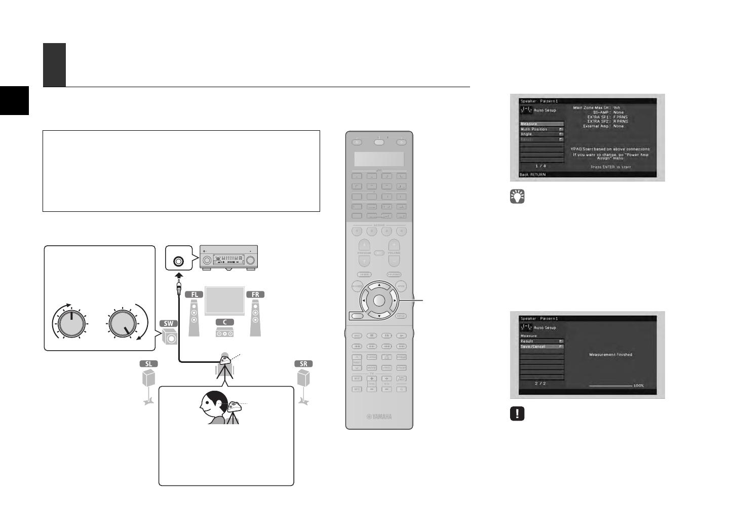
YPAO MIC
VOLUME HIGH CUT
CROSSOVER/
MIN MAXMIN MAX
Unidad (parte delantera)
Coloque el micrófono YPAO en la
posición de escucha (a la misma altura de
sus oídos). Se recomienda utilizar un
trípode como soporte para el micrófono.
Puede utilizar los tornillos del trípode para
fijar el micrófono en su sitio. (No se tiene
en cuenta la dirección del micrófono.)
Micrófono
YPAO
Altura del
oído
Encienda el altavoz de
subgraves y ajuste su volumen
a la mitad. Si se puede ajustar
la frecuencia de cruce, póngala
al máximo.
1
Conecte el micrófono YPAO a la toma
YPAO MIC del panel delantero.
Aparece la siguiente pantalla en el TV.
Para cancelar la operación, desconecte el micrófono YPAO
antes del inicio de la medición.
2
Para iniciar la medición, utilice las teclas
del cursor para seleccionar “Measure”
ypulse ENTER.
La medición comenzará al cabo de 10 segundos.
La siguiente pantalla aparece en el TV cuando
acaba la medición.
Si aparece algún mensaje de error (como E-1) o de
advertencia (como W-2), consulte “Mensajes de error”
o “Mensajes de advertencia” en el “Manual de Instrucciones”.
Si aparece el mensaje de advertencia “W-1:Out of Phase”,
compruebe “Si aparece “W-1:Out of Phase”” (página
siguiente).
RX-A3020_2020_esg_RL.fm Page 6 Wednesday, May 30, 2012 4:39 PM
Es 7
3
Utilice las teclas del cursor para
seleccionar “Save/Cancel” y pulse ENTER.
4
Utilice las teclas del cursor para
seleccionar “SAVE” y pulse ENTER.
5
Desconecte el micrófono YPAO de la
unidad.
Con esto ha finalizado la optimización de los ajustes
de los altavoces.
Siga el procedimiento que se indica a continuación
para comprobar las conexiones de los altavoces.
Dependiendo del tipo de altavoces o el entorno de la
sala, puede aparecer este mensaje, incluso si los
altavoces están correctamente conectados.
a Utilice las teclas del cursor para seleccionar “Result”
y pulse ENTER.
b Utilice las teclas del cursor para seleccionar “Wiring”.
c Compruebe las conexiones del cable (+/–) del altavoz
que se han identificado como “Reverse” en el mensaje de
advertencia.
Si el altavoz está conectado correctamente:
Puede guardar la configuración actual.
Pulse RETURN y continúe al paso 3.
Si el altavoz está conectado incorrectamente:
Apague la unidad, vuelva a conectar el cable del
altavoz e intente realizar de nuevo el proceso de
medición YPAO.
El micrófono YPAO es sensible al calor, por lo que no debe
colocarse en ningún lugar en el que pueda estar expuesto a la
luz solar directa o a altas temperaturas (como en la parte
superior de un equipo de AV).
Si aparece “W-1:Out of Phase”
RX-A3020_2020_esg_RL.fm Page 7 Wednesday, May 30, 2012 4:39 PM
8 Es
Reproduzcamos ahora un BD/DVD.
Recomendamos reproducir audio multicanal (canales
-5.1 o más) para apreciar el sonido surround producido
por la unidad.
1
Pulse AV 1 para seleccionar “AV 1” como
fuente de entrada.
2
Inicie la reproducción en el reproductor
BD/DVD.
3
Pulse STRAIGHT repetidamente para
seleccionar “STRAIGHT”.
Para comprobar si todos los altavoces emiten sonidos
correctamente, pulse STEREO repetidamente para
seleccionar “9ch Stereo”.
4
Pulse VOLUME para ajustar el volumen.
Con esto ha finalizado el procedimiento de
configuración básica.
El sonido sólo se emite por los altavoces delanteros
durante la reproducción de audio multicanal
Compruebe el ajuste de la salida de audio digital del
reproductor BD/DVD.
Se puede ajustar en salida de 2 canales (como PCM).
No se escucha ningún sonido de un altavoz específico
Consulte “Resolución de problemas” en el “Manual de
Instrucciones”.
6 Reproducción de un BD/DVD
SOURCE
RECEIVER
AV
AUDIO
1 2 3 4
5 6 7
V-A UX
1 2 3 4
MULTI
PHONO
USB NET
TUNER
[ C ][ A ] [ B ]
CLASSICAL
LIVE
CLUB
ENTERTAIN
MOVIE
STEREO STRAIGHT
INPU
T
PURE
DIRECT
MUTE
TV
SCENE
1 2 3 4
PROGRAM
VOLUME
TV VOL
MUTE
MODE
TO
P MENU
RETURN DISPLAY
POP-UP/MEN
U
TV CH
PRESET
ENTER
ON SCREEN
OPTION
SOU
R
CE
R
E
C
EIV
E
R
AV
A
UD
I
O
2
3
4
5
6
7
V-A
U
X
1
2
3
4
MUL
TI
L
L
PH
O
N
O
U
S
B
N
E
T
TUNE
R
[
C
]
[
A
]
[
B
]
AV 1
STRAIGHT
STEREO
VOLUME
Si el sonido surround no funciona
OUT
1
IN
OUT
2
VOLUME
MUTE
DRCADAPTIVE
3
ZONE
2
STEREO
ENHANCER
SLEEP
HD
TUNED
PRE
AMP
PARTY
ZONE
3
ZONE
4
HD
TAG
DOCK
SBLPL SBRSB PR
SW1
SL
SW2SW
SR
PL
CLR
PR
A.Sel:Auto
AV1
SPIMP.-
VOLUME
SBL SBR
SW1
SL SR
CLR
STRAIGHT
VOLUME
SBL SBR
SW1
SL SR
CLR
Main:Volume
Muchas más funciones
La unidad posee varias funciones más.
Consulte el “Manual de Instrucciones” en el
CD-ROM suministrado para sacar el máximo
partido a la unidad.
Conexión de otros
dispositivos de reproducción
Conecte dispositivos de audio (como
reproductor CD), consolas de juegos,
videocámaras y muchos otros.
Selección del modo de sonido
Seleccione el programa de sonido que desee
(CINEMA DSP) o el decodificador surround que
sea apropiado para películas, música, juegos,
programas deportivos y otros usos.
Reproducción desde un iPod
Mediante un cable USB suministrado con el iPod,
puede escuchar música del iPod en la unidad.
Escucha de radio FM/AM
Reproducción de música
almacenada en un dispositivo
de almacenamiento USB
Reproducción del contenido de
red
Selección de la fuente de
entrada y los ajustes favoritos
de una vez
Para obtener más información, consulte “Qué
puede hacer con la unidad”.
RX-A3020_2020_esg_RL.fm Page 8 Wednesday, May 30, 2012 4:39 PM
© 2012 Yamaha Corporation Printed in Malaysia ZC34960
RX-A3020_2020_esg_RLH_cover4.fm Page 2 Wednesday, May 2, 2012 2:13 PM
Black process 45.0° 240.0 LPI
  • Page 1 1
  • Page 2 2
  • Page 3 3
  • Page 4 4
  • Page 5 5
  • Page 6 6
  • Page 7 7
  • Page 8 8
  • Page 9 9
  • Page 10 10
  • Page 11 11
  • Page 12 12
  • Page 13 13
  • Page 14 14
  • Page 15 15
  • Page 16 16
  • Page 17 17
  • Page 18 18

Yamaha RX-A2020 Guía de instalación

Categoría
Receptores AV
Tipo
Guía de instalación
Este manual también es adecuado para

En otros idiomas