Dan Dugan Sound Design DUGAN-MY16 Manual de usuario
- Categoría
- Mezcladores de audio
- Tipo
- Manual de usuario
Este manual también es adecuado para

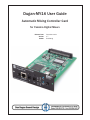
Dugan-MY16 User Guide
Automatic Mixing Controller Card
for Yamaha Digital Mixers
Release Date December 2013
Version 2.7
Author Rob Wenig

Important Safety Instructions and Warnings
The Dugan-MY16’s circuitry is made in the USA and meets applicable national safety
standards.
Safety Instructions
1. Read these instructions.
2. Keep these instructions.
3. Heed all warnings.
4. Follow all instructions.
5. Do not use this apparatus near water.
6. WARNING! To reduce the risk of fire or electric shock, do not expose this appa-
ratus to rain or moisture.
7. Clean only with dry cloth.
8. Do not block any ventilation openings. Install in accordance with the manufac-
turer’s instructions.
9. Do not install near any heat sources such as radiators, heat registers, stoves, or
other apparatus (including amplifiers) that produce heat.
10. Only use attachments/accessories specified by the manufacturer.
11. Unplug this apparatus during lightning storms or when unused for long periods
of time.
12. WARNING! Refer all servicing to qualified service personnel. Servicing is re-
quired when the apparatus has been damaged in any way, such as liquid has been
spilled or objects have fallen into the apparatus, the apparatus has been exposed
to rain or moisture, does not operate normally, or has been dropped.
13. WARNING! No user serviceable parts inside.

FCC
1. IMPORTANT NOTICE: DO NOT MODIFY THIS UNIT! This product, when in-
stalled as indicated in the instructions contained in this manual, meets FCC re-
quirements. Modifications not expressly approved by Dan Dugan Sound Design
may void your authority, granted by the FCC, to use the product.
2. IMPORTANT: When connecting this product to accessories and/or another
product use only high quality shielded cables. Failure to follow instructions could
void your FCC authorization to use this product in the USA.
3. NOTE: This product has been tested and found to comply with the requirements
listed in FCC Regulations, Part 15 for Class “B” digital devices. Compliance with
these requirements provides a reasonable level of assurance that your use of this
product in a residential environment will not result in harmful interference with
other electronic devices. This equipment generates/uses radio frequencies and, if
not installed and used according to the instructions found in the users manual,
may cause interference harmful to the operation of other electronic devices.
Compliance with FCC regulations does not guarantee that interference will not
occur in all installations.
If this product is found to be the source of interference, which can be determined
by turning the host unit OFF and ON, please try to eliminate the problem by using
one of the following measures: Relocate either this product or the device that is be-
ing affected by the interference. Utilize power outlets that are on different branch
(circuit breaker or fuse) circuits or install AC line filter/ s. In the case of radio or
TV interference, relocate/ reorient the antenna. If the antenna lead-in is 300 ohm
ribbon lead, change the lead-in to co-axial type cable. If these corrective measures
do not produce satisfactory results, please contact the local retailer authorized to
distribute this type of product. If you can not locate the appropriate retailer, please
contact Dan Dugan Sound Design.
The above statements apply ONLY to those products manufactured by Dan Dugan
Sound Design.
This device complies with Part 15 of the FCC Rules. Operation is subject to the fol-
lowing two conditions:
1. This device may not cause harmful interference.
- AND -
2. This device must accept any interference received, including interference that
may cause undesired operation.
This Class B digital apparatus complies with Canadian ICES-003.

Precautions
Failure to observe the following warnings may lead to fatality or serious injury from
fire or electric shock.
1. Before installing the card, you must refer to the owner’s manual of the host device
or to the Yamaha website (“Guidance on the use of Mini-YGDAI cards” page) to
verify that your host device supports this card, and to verify the number of cards
that can be installed in combination with other Yamaha or third-party cards.Ya-
maha website: http://www.yamahaproaudio.com/
2. If one or more cards in a combination not endorsed by Yamaha are installed in a
Yamaha device, electrical shock, fire, or malfunction may occur. Please note that
the Dugan-MY16 can be used with the following models of Yamaha product that
accept option I/O cards (Yamaha MY series and third-party products):
PM5D/PM5D-RH, DSP5D, M7CL-48ES, M7CL-48, M7CL-32, MTX5-D, LS9-32,
LS9-16, DM2000, DM1000, 02R96, 01V96, DME64N, DME24N, CL1, CL3, CL5.
3. To use the Dugan-MY16 card in a DM2000 or 02R96, the following system soft-
ware is required: DM2000 Version 1.14 or later. 02R96 Version 1.06 or later. See
the Yamaha Web site for upgrade information.
4. Do not attempt to disassemble or modify the card. Do not apply excessive force
to board connectors or other board components. Mishandling the board may
lead to shock, fire hazard, or equipment failure.
5. To eliminate shock hazard, disconnect the power cable from the main unit before
installing this card.
CAUTION: Failure to observe the following precautions may lead to personal injury, or may result in
damage to equipment or other property.
6. Do not touch the board’s metallic leads (pins) when handling the card. Pins are
sharp and may cause hand cuts.
7. The card is electrostatic-sensitive. Before handling the card, you should briefly
touch the main unit’s metal casing with your bare hand to drain any static charge
from your body.
CAUTION: Dan Dugan Sound Design assumes no responsibility for data loss, equipment damage, or
injury caused by inappropriate handling or usage.

Warranty Statement
Dan Dugan Sound Design warrants that Dugan-MY16 hardware will be free from defects
in components and workmanship for a period of 12 months from the date of invoice.
During the warranty period, Dan Dugan Sound Design will cover the cost of all parts
and labor to remedy the defect, or replace products which prove to be defective.
Dan Dugan Sound Design is not obliged to honor this warranty if the hardware has
failed to be maintained and operated as specified by Dan Dugan Sound Design, in the
accompanying documentation, or other than in accordance with industry standards.
Defects caused by unauthorized modifications, misuse, negligence, act of God or ac-
cident are not covered by this warranty.
Software is provided as a convenience, but due to the wide variety of computer sys-
tems, cannot be guaranteed to work. This Limited Warranty is exclusive and no other
warranty is expressed or implied. Dan Dugan Sound Design does not warrant that D an
Dugan Sound Design software, or any third-party software, is error free.


Dugan-MY16 User Guide
7
Table of Contents
Chapter 1: Introduction ............................................................................................. 9
Theory of Operation................................................................................. 10
Remote Control and Software............................................................. 11
Chapter 2: Installation and Linking................................................................. 13
Installing the Dugan-MY16 Card ........................................................ 13
Choose an Operating Mode ................................................................ 14
Connecting to a Computer or Network ............................................ 16
Linking Multiple Dugans........................................................................ 21
Chapter 3: The Dugan Control Panel ............................................................. 23
Top Pane...................................................................................................... 24
Add Units Manually.............................................................................. 24
Select Units to Display ........................................................................ 25
Setting Controls ........................................................................................ 25
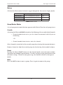
Naming Units and Channels................................................................. 26
Channel Pane ............................................................................................ 26
Level Indicator...................................................................................... 27
Bypass .................................................................................................. 28
Channel Modes .................................................................................... 28
Preset .................................................................................................. 29
Channel Groups.................................................................................... 30
Channel Override ................................................................................. 30
Meters .................................................................................................. 31
Weight .................................................................................................. 31

Dugan-MY16 User Guide
8
Master Pane ............................................................................................... 34
Indicators .............................................................................................. 34
Controls................................................................................................. 36
Typical Operation...................................................................................... 38
Muting Mics on an LS9 .......................................................................... 39
Chapter 4: Updates..................................................................................................... 41
Chapter 5: Specifications....................................................................................... 43

Dugan-MY16 User Guide
9
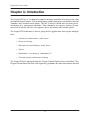
Chapter 1: Introduction
The Dugan-MY16 is a 16-channel automatic mixing controller that plugs into a slot
on Yamaha digital mixers. This multichannel audio signal processor patches into the
Yamaha’s mic channel insert points. The MY16 detects which mics are being used,
and makes fast, transparent crossfades. This eliminates late upcuts, reduces system
noise and feedback, and lets the engineer focus on balance and sound quality.
The Dugan-MY16 enhances a diverse group of live applications that require multiple
mics:
• Conference reinforcement, video trucks
• Houses of worship
• Film and television dialogue, reality shows
• Theater
• Boardrooms, civic meetings, community TV
• Teleconferencing and distance learning
The Dugan-MY16 is operated from the Dugan Control Panel for Java (included). The
Dugan Control Panel for iPad (sold separately) performs the same function on an iPad.

Dugan-MY16 User Guide
10
Theory of Operation
The Dugan-MY16 uses the Dugan Speech System™, a patented and trademarked
automatic mixing function that distributes the gain of one open microphone over
the entire system. This results in a natural one-mic ambience with minimal noise
or feedback. The Dugan Speech System does not limit, compress, or control levels. It per-
forms just one critical function: cuing multiple live mics in situations with unpre-
dictable dialogue. It is essential to distinguish this behavior from the distracting
fluctuation of levels and uneven ambience produced by a conventional noise gate.
When one person talks at a time, the Dugan Speech System rapidly fades that mic’s
gain up and the others down. When the speaker pauses, that mic fades down and the
others up, so the gain of all mics sums to equal that of one mic at full gain. When
the next person talks, the system fades that mic’s gain up and the others down. The
result sounds like passing one mic among several speakers.
When several people talk at once, the gain is shared among active mics. All mics sound
normal when used but there is no change in ambience, noise buildup, or feedback.
While people are talking, use the Yamaha mixer’s faders to set appropriate relative
levels for each mic channel. You can leave the faders up when the mics are not used
because the Dugan Speech System cues the mics up when needed.
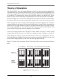
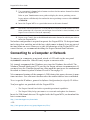
Figure 1-1 shows four snapshots of the Dugan Speech System in action with three
mics.
Figure 1-1 Dugan Speech System
Sound
No one speaking Mic 2 speaking Mic 3 speaking Mics 2 and 3 speaking
at mics (dB)
40
50
60
70
Resulting
automix
gains (dB)
-30
-20
-10
0
1234

Dugan-MY16 User Guide Introduction
11
Frame 1: No one is speaking and the sound levels at all mics are low. The system fades
all channels to a medium gain that sums to one mic at full gain.
Frame 2: One person speaks alone. The system automatically fades their gain to full,
and turns the other two inputs down.
Frame 3: The first person finishes speaking and a second person begins. The system
automatically fades the new speaker’s input gain to full, and turns the other two down.
Frame 4: Two people speak simultaneously. The system automatically shares the
gain between them, and turns the other input down.
Remote Control and Software
Two Java applets are included on a thumb drive or CD, or can be downloaded from
our website:
• The Dugan Control Panel offers expanded operational capabilities (see Chapter 3:
The Dugan Control Panel).
• The Dugan Utility helps you connect to a network and update the firmware (see
Chapter 4: Updates).
The Dugan-MY16 can be controlled with:
• the Dugan Control Panel for Java (included);
• the Dugan Control Panel for iPad (sold separately)
• ASCII commands via Ethernet (contact Dan for information).
Subscribe to the duganusers Yahoo group to be notified when updates are available.

Dugan-MY16 User Guide
12

Dugan-MY16 User Guide
13
Chapter 2: Installation and Linking
This chapter explains how to:
• Install Dugan-MY16 card(s);
• Install the Dugan Control Panel for Dugan-MY16 cards and external Dugans;
• Link Dugan-MY16 cards and external Dugans into a single unified automatic mix-
ing controller.
Installing the Dugan-MY16 Card
Most Yamaha mixers have multiple slots, each of which has 16 channels. The Dugan-
MY16 can be installed in any available slot. The table below shows the current list of
Yamaha mixers that are compatible with the Dugan-MY16.
See YamahaProAudioSupport for the most up to date list.
To begin installing your Dugan-MY16, find your mixer model in the table below, and
set the Native
–Legacy switch accordingly. The Native–Legacy switch maintains Ya-
maha’s compatibility with its older mixers. Some older Yamaha mixers that require
the Legacy setting do not display the correct names for plug-in cards in their insert
patching screen.
* With LS9 firmware v1.21 or earlier, the LS9 insert patch points are pre-fader only. To properly mute
mixer channels, you must use the Dugan Control Panel for Java (included) or the Dugan Control Panel
for iPad (sold separately).
Yamaha Mixer Model Native-Legacy Switch
CL1 Native
CL3 Native
CL5 Native
PM5D/PM5D-RH Native
DSP5D Native
M7CL-48ES Legacy
M7CL-48 Legacy
M7CL-32 Legacy
MTX5-D Native
LS9-32* Legacy
LS9-16* Legacy
DM2000 Legacy
DM1000 Legacy
02R96 Legacy
01V96/01V96i Legacy
DME64N Native
DME24N Native

Dugan-MY16 User Guide
14
Choose an Operating Mode
The operating mode determines sample rate, linking, and channel count. Set the
Yamaha mixer’s sample rate before setting the operating mode (see your Yamaha
mixer’s user guide to learn how).
Choose one of the three operating modes:
Standard
Sixteen Dugan mixing channels at 44.1 or 48 kHz
ADAT I/O connectors can link multiple Dugan units
High-rate
Eight Dugan mixing channels at 88.2 or 96 kHz
ADAT I/O connectors can link multiple Dugan units
Shared
Eight Dugan mixing channels at 44.1 or 48 kHz
The ADAT I/O connectors serve as a general-purpose interface that is available
for patching on channels 9–16 of the Dugan-MY16’s slot. These channels are
unrelated to Dugan mixing and can be used as additional Yamaha mixer I/O.
To use channels 9–16 (as with any digital input), an appropriate synchroniza-
tion source must be selected (see your Yamaha mixer’s user guide).

Dugan-MY16 User Guide Installation and Linking
15
To configure and install the Dugan-MY16 card:
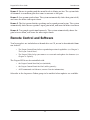
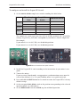
1. Set the 48 kHz–96 kHz sample rate switch according the table below.
The sample rate switch represents low (44.1 or 48 kHz) and high (88.2 or 96 kHz)
settings, respectively, that must correspond to your mixer’s current sample rate.
For example,
If your mixer is set to 44.1 kHz, use the 48 kHz position.
If your mixer is set to 88.2 kHz, use the 96 kHz position.
Figure 2-1 Circuit board and rear panel switches
2. Install the Dugan-MY16 card according to the instructions in your mixer’s user
guide.
3. Turn on the mixer.
If you are using Shared mode, an appropriate synchronization source must be
selected for channels 9–16. See your Yamaha mixer’s user guide for details.
4. Press and hold the RESET button for 3 seconds to restore the Dugan-MY16’s factory
default settings.
5. Set the rear panel LINK–AUDIO switch to the position corresponding to the selected
operating mode (see table above).
6. Set the NORM–SLAVE switch to NORM (up) for unlinked operation.
Mixer Sample
Rate
Sample Rate
Switch
LINK-AUDIO Switch
Standard
44.1 kHz 48 kHz LINK
48 kHz 48 kHz LINK
High Rate
88.2 kHz 96 kHz LINK
96 kHz 96 kHz LINK
Shared
44.1 kHz 48 kHz AUDIO
48 kHz 48 kHz AUDIO

Dugan-MY16 User Guide
16
7. Use your mixer’s channel select button to select the first mixer channel in which
to insert the Dugan-MY16.
Refer to your Yamaha mixer user guide to display the insert patching screen.
Legacy mixers will identify the card on the insert patching screen as either MY16AT
or MY8AE96.
8. Insert the Dugan-MY16 as a post-fader insert on this mic channel.
NOTE: LS9 mixers with firmware version 1.2 and older do not allow post-fader inserts. You must
either update the LS9’s firmware, use the Dugan Control Panel for Java (included), or the
Dugan Control Panel for iPad (sold separately).
9. Repeat steps 7 and 8 for each additional mixer mic channel in which you wish to
insert the Dugan-MY16.
No further configuration is required to operate the Dugan-MY16. We designed nom-
inal settings that work fine out of the box, which comes in handy if you are pressed
for time before an event. However, to take full advantage of the Dugan-MY16’s ad-
vanced features, we recommend installing the Dugan Control Panel software.
Connecting to a Computer or Network
To connect to a computer or network, attach a CAT5 cable to the rear panel
10/100BASE-T connector. Older PCs may require a crossover cable.
We strongly recommend that Windows users turn the Windows firewall off. The
Windows Firewall blocks port 9776 used by the Dugan software to communicate. If
you must leave the Windows firewall on, either open this port or use the workaround
described in Connecting when Windows Firewall is On on page 21.
We recommend turning off the computer’s WiFi during this process because it some-
times interferes. You can turn it back on after the connection has been established.
To set a specific IP address, proceed to Software Configuration for a Specific IP Address.
Two Java applets are provided with the Dugan-MY16:
• The Dugan Control Panel offers expanded operational capabilities.
• The Dugan Utility helps you connect to a network and update the firmware.
Insert the USB thumb drive or CD supplied with the Dugan-MY16, or download the
latest version from:
http://www.dandugan.com/downloads
- OR -
http://tech.groups.yahoo.com/group/duganusers/files/

Dugan-MY16 User Guide Installation and Linking
17
Establishing Network Connections
We recommend completing your network connection with a computer before using the
iPad app.
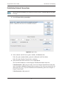
1. Launch Dugan-Utility-yyyymmdd.jar.
Figure 2-2 Dugan Utility
2. Wait a minute and if the list pane is blank, click Refresh List.
If the list pane remains blank, proceed to Manually Add Unit below.
If the list pane displays Dugan units, continue.
3. Click on the first unit in the list so it is highlighted.
The Network Parameters section displays information about that unit.
If Unit Reachable is YES, you are ready to use the Dugan Control Panel with that
unit. If you have additional Dugan units to connect, select the next unit in the list
and repeat this step. If you are finished with installation, proceed to Chapter 4:
Dugan Control Panel.
If Unit Reachable is NO, proceed.
iPad

Dugan-MY16 User Guide
18
4. Press and hold the rear panel NETWORK RESET button for 3 seconds.
This resets the following network parameters to their factory default value.
*xx = last two digits of serial number, unless 00, then use 100
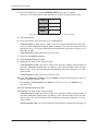
5. Click Refresh List.
6. Click on the first unit in the list so it is highlighted.
If Unit Reachable is YES, you are ready to use the Dugan Control Panel with that
unit. If you have additional Dugan units to connect, select the next unit in the list
and repeat Step 3. If you are finished with installation, proceed to Chapter 4: Du-
gan Control Panel.
If Unit Reachable is NO, proceed to the next step.
7. Select the Use DHCP parameter.
8. Click Send New Params to Unit.
9. Highlight the unit in the list pane again.
If Unit Reachable is YES, this unit is ready to use with the Dugan Control Panel. If
you have additional Dugan units to connect, select the next unit in the list and
repeat Step 3. If you are finished with installation, proceed to Chapter 4: Dugan
Control Panel.
If Unit Reachable is NO, proceed to the next step.
10.Copy This Computer’s IP Address to the IP Address field, and increase the value in
the last (fourth) group by one.
For example, if This Computer’s IP Address is 192.168.1.101, set IP Address to
192.168.1.102.
11.Click Send New Params to Unit.
12.Highlight the unit in the list pane again.
If Unit Reachable is YES, this unit is ready to use with the Dugan Control Panel. If
you have additional Dugan units to connect, select the next unit in the list and
repeat Step 3. If you are finished with installation, proceed to Chapter 4: Dugan
Control Panel.
If Unit Reachable is NO, see Using the Internally Stored Dugan Control Panel on page 19.
IP Address
192.168.1.xx*
Netmask
255.255.255.0
Gateway
192.168.1.254
DHCP
off

Dugan-MY16 User Guide Installation and Linking
19
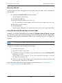
Manually Add Unit
If the Dugan unit does not appear in the Dugan Utility list pane, you can manually
add the unit:
1. Hold down NETWORK RESET for three seconds.
This performs a network reset.
2. Click Manually Add Unit.
3. Enter the default IP address: 192.168.1.xx
xx = last two digits of serial number, unless they are 00, in which case enter 100.
4. Click OK to exit the dialog.
5. Click Refresh List.
If the list pane is still blank, see Using the Internally Stored Dugan Control Panel below.
Using the Internally Stored Dugan Control Panel
Normally, the Dugan Control Panel is run from the Dugan-Control-Panel-vxxx.jar
file. However, if for any reason you do not have that file or an Internet connection,
you can run the Dugan Control Panel from a copy stored in the unit (see Chapter 4:
Updates).
It is not currently possible to run the internally stored Dugan Control Panel from an iPad.
To run the internally stored Dugan Control Panel:
1. Launch your browser.
2. Enter the IP Address of the unit.
3. If you do not know its IP Address, press and hold the rear panel NETWORK RESET
button for 3 seconds.
The IP Address is set to 192.168.1.xx (xx = last two digits of the unit’s serial num-
ber, unless 00, then use 100).
4. Since the Top Pane will be empty, open a separate browser tab for each unit you
wish to operate, and enter its IP Address.
If this does not work, consult the duganusers Yahoo group (http://tech.groups.ya-
hoo.com/group/duganusers
) or contact Dan.
iPad

Dugan-MY16 User Guide
20
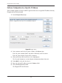
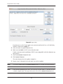
Software Configuration for a Specific IP Address
This section explains to users with IT expertise how to set a specific IP address for any
Dugan unit on the network.
1. Launch Dugan-Utility-vxx.jar.
Figure 2-3 Dugan Utility
2. Wait a minute and if the list pane is blank, click Refresh List.
If the list pane remains blank, skip back to Manually Add Unit above.
If the list pane displays Dugan units, continue.
3. Click on the first unit in the list so it is highlighted.
The Network Parameters section displays information about that unit.
4. If Use DHCP is selected, de-select it.
5. Enter the desired IP address into the IP Address field.
6. Click Send New Params to Unit.
The
Dugan-MY16 will reboot.

Dugan-MY16 User Guide Installation and Linking
21
Connecting when Windows Firewall is On
The Windows Firewall blocks access to port 9776 that is used by the Dugan software.
If you must leave the Windows Firewall on, you can operate the Dugan Control Panel
in a browser window with one connected unit per tab.
1. Enter the Dugan-MY16’s IP address directly in the browser’s address field.
The browser uses the Dugan Control Panel that is stored in the Model E-1A’s hard-
ware, not the version that you may have downloaded to your computer.
The unit will not show up in the Top Pane but the control panel will still work.
2. If you have multiple Dugan units, create a browser tab for each one and enter its
IP Address.
3. Switch tabs to control different units.
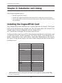
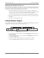
Linking Multiple Dugans
Up to eight Dugan units can be linked into a single automatic mixing system. One
unit must be set to be the master and the others slaves.
Figure 2-4 Linking multiple Dugans
1. Designate one unit as the master by setting the NORM-SLAVE switch on the rear
panel to NORM (up).
2. Designate any other units as slaves by setting their NORM-SLAVE switches on the
rear panel to SLAVE (down).
3. Use ADAT (Toslink) cables to link units in a ring network (see above).
Note that all LINK IN and OUT connectors are used to create the ring.

Dugan-MY16 User Guide
22

Dugan-MY16 User Guide
23
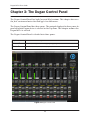
Chapter 3: The Dugan Control Panel
The Dugan Control Panel has both Java and iPad versions. This chapter discusses
the Java version and notes the iPad app’s few differences.
The Dugan Control Panel has three panes. The controls displayed in these panes de-
pend on which Dugan device is selected in the Top Pane. This chapter assumes the
Dugan-MY16 is selected.
The Dugan Control Panel is divided into three panes:
Figure 3-1 Dugan Control Panel
Top Pane
icons for all connected Dugan units
Channel Pane
man, auto, mute, preset, override, group, weight, bypass, and channel name controls
Master Pane
OVERRIDE, PRESET, MUTE, meters, system, and reset controls

Dugan-MY16 User Guide
24
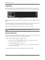
Top Pane
The Top Pane displays all connected Dugan units. The active unit is enclosed by a
yellow rectangle. Click on another unit to select it and deselect the previous unit.
Figure 3-2 Top Pane
Some Yamaha mixers have multiple card slots that can be used for additional Dugan-
MY16s.
All connected Dugan units appear in the Top Pane. If all connected units do not ap-
pear in the Top Pane, see Establishing Network Connections on page 17.
To display a unit’s IP address, hover the mouse over the unit’s name.
To display a unit’s IP address, touch and hold the unit’s name.
Add Units Manually
To add a unit manually with a known IP address, click the + sign at the right of the
Top Pane and enter the IP address in the dialog that appears.
To add a unit manually without a known IP address:
1. Hold down the blue NETWORK RESET button on the rear panel for 3 seconds.
2. Click the + sign at the right of the Top Pane.
3. Enter the default IP address: 192.168.1.xx
xx = last two digits of serial number, unless they are 00, in which case enter 100.
4. Click OK to exit the dialog.
To display a unit’s IP address, hover the mouse over the unit’s name.
iPad

Dugan-MY16 User Guide The Dugan Control Panel
25
Select Units to Display
The Dugan-MY16 is set up by default to find all available units connected to the net-
work automatically. Some facilities have multiple studios on the same network that
operate independently. In that case, you may want to restrict the units shown in the
Top Pane to those in your studio. To do this:
1. Hover the mouse cursor over the names of the units that you want to display, and
note their IP addresses.
2. Ctrl-click on the + sign at the right of the Top Pane.
The + sign turns red.
3. Quit and relaunch the Dugan Control Panel.
It opens with Auto Detect Disabled in the Top Pane
4. Click on the red + sign, and enter the IP address of the first unit you want to add.
5. Repeat step 4 until your units all appear in the Top Pane.
Manually added units must also be removed manually. To remove manually added
units from the Top Pane, shift-click on the
+ sign. A dialog appears to confirm that
they have been removed.
To restore automatic detection, ctrl-click on the + sign, which turns white.
Setting Controls
Controls can be adjusted five ways:
• Enter a dB value in the numeric field.
• Drag in the numeric field (not on iPad).
When a slider is present:
• Drag the slider up or down.
• Click in the slider track to raise or lower the value by 0.5 dB.
• Ctrl-click anywhere on the slider to reset its value to 0 (touch and hold on iPad).

Dugan-MY16 User Guide
26
Naming Units and Channels
Connected units are displayed in the top pane in alphabetical order. To display them
in your own order, use names with number prefixes.
To name a unit and its channels:
1. Select a unit in the top pane.
2. Select the yellow text in the right pane (under the Dugan logo) and type a name.
3. Press the Enter key on the keyboard to set the name.
4. To name a channel, select the yellow text and type a name.
5. Press the Enter key on the keyboard to set the name.
Channel naming is cleared by pressing reset (see page 36).
When the unit is powered up, channel modes are determined by their preset modes;
all other settings are retained.
After configuring settings with the Dugan Control Panel, it can be disconnected. All
settings are retained and the unit continues to function on its own.
Channel Pane
The Channel Pane contains the controls and indicators for each channel. Channels
are always in one of three modes:
man, auto,ormute. The active channel mode illu-
minates. All transitions are made with a smooth, rapid fade. Select a channel mode
by pressing the individual mode buttons or the Master
PRESET button.
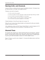
Figure 3-3 shows a typical system: channels 1–4 in
auto with ambient noise, and chan-
nels 5–8 in
mute.

Dugan-MY16 User Guide The Dugan Control Panel
27
Figure 3-3 Channel Pane
Level Indicator
Each channel has a level LED that lights green when the audio level is adequate for
automatic mixing. It should remain green when no one is talking.
•Ifthelevel indicator blinks, raise the Yamaha mixer’s input gain.
•Ifthelevel LED lights red, lower the Yamaha mixer’s input gain until it stays green
at all times.

Dugan-MY16 User Guide
28
Bypass
When bypass is active, the signal passes through without automixing. That channel
appears inactive, with all lights extinguished.
Figure 3-4 bypass button lit
To deactivate bypass, you can:
• Click bypass again;
-OR-
• Click any of the three channel mode buttons.
Channel Modes
Man
Changing channel modes initiates a half-second fade to the new mode. Like radio
buttons, you can only choose one mode at a time.
Figure 3-5 Channel modes
In man mode there is no automixing, and the signal passes through at unity gain.
Man and bypass modes perform similar functions, but we recommend using man dur-
ing live mixing to prevent clicks.

Dugan-MY16 User Guide The Dugan Control Panel
29
Auto
This is the normal Dugan automixing mode.
Mute
The channel is muted when mute is active.
Preset
Use the preset function to store your favorite channel mode settings, which may be
restored by pressing the Master
PRESET button. When the unit powers up, the channels
default to their preset modes.
Figure 3-6 Channel preset (left) and Master PRESET (right) buttons
To set channel presets:
1. Click the channel preset button next to the desired channel mode button.
2. For all unused channels, click the preset button next to the mute button.
The preset indicators should mirror your normal working combination of input modes.
The normal condition can then be restored by pressing the Master
PRESET button.
channel preset
buttons
Master
PRESET
button

Dugan-MY16 User Guide
30
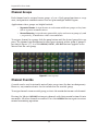
Channel Groups
Each channel can be assigned to one group: a, b, or c. Each group functions as a sep-
arate, independent automatic mixer that can span multiple linked Dugans.
Applications where groups are helpful include:
• Separate Rooms: Assign the mics in each room to different groups so they func-
tion as separate automatic mixers.
• Stereo Panning: Assign the mics panned left, right, and center to groups a, b, and
c, respectively, to maintain a stable stereo ambience.
To assign a channel to a group, click the group button until the desired group letter ap-
pears. The channel strip background is tinted green (
group b) or blue (group c); group a is
not tinted (Figure 3-7). A set of
OVERRIDE, PRESET, and MUTE buttons appears in the
Master Pane for each group.
Figure 3-7 Channel groups
Channel Override
Override can be used to instantly mute all mics except one (the host or chairperson).
However, any number of mics can be included in the override group.
To assign channels to an override group, activate the
override button on each channel.
Pressing the Master
OVERRIDE button puts channels with their override buttons lit into
man mode. All other channels are muted. Press the OVERRIDE button again to restore
normal automixing operation.

Dugan-MY16 User Guide The Dugan Control Panel
31
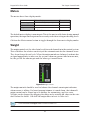
Meters
The meters have three display modes.
Table 3-1 Meter modes
The default meter display is auto mix gain. This is the most useful choice during normal
operation; the input and output meters are only used when setting or checking levels.
Click on the Master
meters button to toggle through the three meter display modes.
Weight
The weight controls set the side-chain levels for each channel into the control system.
This establishes the relative sensitivity of the automatic mix for the channels in use.
They do not change the mix levels. When the
weight controls are balanced, each mic has
an equal opportunity to take over the system: when one person talks into one mic,
he/she gets all the
auto mix gain and the others get turned down.
Figure 3-8 Weight controls
The weight controls should be used to balance the channel auto mix gain indicators
when no one is talking. If a board preamp trimmer is turned down, that channel’s
weight control can be turned up to re-balance the automixing, and vice-versa.
Weights can be changed by dragging the sliders or by entering dB values in the win-
dows below the sliders. Ctrl-click the
weight slider to reset its value to 0.
Touch and hold the weight slider to reset its value to 0.
Meter Displays Meter Color
auto mix gain
action of the Dugan Speech System green
input
input level yellow
output
output level blue
iPad

Dugan-MY16 User Guide
32
It is important to understand that the Speech System works by detecting the ratios of
the levels between channels, not their absolute levels. The
weight control is not a gate
threshold!
The following example explains how weight works (see Figure 3-9).
Raising the
weight control for one channel:
• increases that channel’s auto mix gain display during ambience and decreases it
slightly for the others;
• makes it more difficult for others to speak when someone speaks into the channel
with the higher weight setting.
It is important to understand that this does not set that mic’s level in the mix when
that person speaks alone, but only its sensitivity during automatic mixing compared to
other channels.
Figure 3-9 Changing one channel’s weight control
Lowering the weight control for one channel:
• decreases the auto mix gain display during ambience for that channel and increases
it slightly for the others;
• makes it more difficult for that channel’s talker to be heard over the others.
higher weight lower weight
same
resulting
auto mix gains
input levels

Dugan-MY16 User Guide The Dugan Control Panel
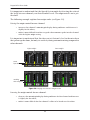
33
For optimal performance, balance the weight controls so the channel gains display ap-
proximately equally when no one is talking. If there is ongoing noise near one mic (e.g.,
computer fan or air vent), suppress it by reducing that channel’s
weight. Of course, you
will hear that noise increase when that talker speaks.
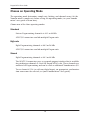
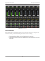
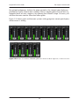
Figure 3-10 shows eight- and four-mic systems with appropriate
auto mix gain displays
when no one is talking.
Figure 3-10 Multiple mic ambience: auto mix gain hovers around -9 dB for eight mics, -6 dB for four mics

Dugan-MY16 User Guide
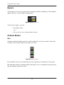
34
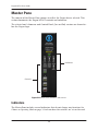
Master Pane
The content of the Master Pane changes to reflect the Dugan device selected. This
section documents the Dugan-MY16’s controls and indicators.
The selected unit’s firmware and Control Panel (Java or iPad) versions are shown be-
low the Dugan logo.
Figure 3-11 Master Pane indicators and controls
Indicators
The Master Pane includes several indicators that do not change any function. See
Choose an Operating Mode on page 14 to learn how the switches are set on the card.
Indicators
Controls

Dugan-MY16 User Guide The Dugan Control Panel
35
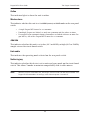
Online
This indicator lights to show the unit is online.
Master-slave
This indicates whether this unit is set to NORM (master) or SLAVE mode on the rear panel
switch.
• A single Dugan-MY16 must be set to master.
• If multiple Dugans are linked, set only one to master and the others to slave.
• If external Dugan automatic mixing controllers are linked with one or more Du-
gan-MY16s, one of the Dugan-MY16s must be set to master.
48k-96k
This indicates whether this unit is set to low (44.1 or 48 kHz) or high (88.2 or 96 kHz)
sample rate on the circuit board switch.
Link-audio
This indicates the operating mode selected on the rear panel switch.
Native-legacy
This indicates whether this device is set to native or legacy mode on the circuit board
switch. This allows Yamaha to maintain compatibility with its older mixers.
NOTE: After all controls have been set, the Dugan Control Panel can be disconnected. The
Dugan-MY16 remembers all settings, even after the power is turned off.

Dugan-MY16 User Guide
36
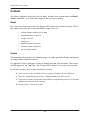
Controls
The Master controls, located on the far right, include reset, system, meters, OVERRIDE,
PRESET, and MUTE. A set of buttons appears for each active group.
Reset
Press the reset button to restore the Dugan-MY16 to factory default settings. This is
the same as pressing the rear panel
RESET button. This sets
• channel modes and presets to auto
• override buttons to inactive
• weights to 0 dB
• groups to a
• bypass buttons to inactive
• channel names to defaults
• meters mode to gain
System
When multiple Dugan units are linked, groups a, b, and c span linked units and operate
as independent automatic mixers.
It is possible to have multiple systems of linked units on your network. These units
will all appear in the Top Pane. The Dugan-MY16 allows 16 systems in a network.
In the rare instance that requires multiple systems:
1. Select the first unit to include in the system by clicking it in the Top Pane.
2. Click the system button and select a unique number for that system.
3. Repeat for each unit in that physically linked system, making sure to use the same
number for each unit in the system.
4. Repeat steps 1–3 for each system.

Dugan-MY16 User Guide The Dugan Control Panel
37
Meters
Click on the Master meters button to toggle through the three meter display modes.
Table 3-2 Meter modes
Group Master Modes
A set of group master mode buttons appears in the Master Pane for each group in use.
Override
Activating the Master OVERRIDE button has the following effect on individual channels:
• Channel override button active: puts the channel in man mode with full gain (no
automixing);
-OR-
• Channel override button inactive: mutes the channel.
Select channel(s) to include in the override group by activating their override button(s).
Remove channel(s) from the override group by deactivating their
override button(s).
Preset
Pressing the Master PRESET button sets the channel modes (man, auto, mute) to those
shown on each channel’s
preset buttons. Use these settings to store your favorite chan-
nel mode settings. When the unit powers up, the channels default to their preset
modes.
Mute
Press the MUTE button to mute a group. Press it again to unmute the group.
Meter Displays Meter Color
auto mix gain
action of the Dugan Speech System green
input
input level yellow
output
output level blue

Dugan-MY16 User Guide
38
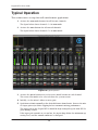
Typical Operation
This section creates a setup that will work for most applications.
1. Activate the auto mode buttons for all live mic channels.
The figure below shows channels 1–4 in auto mode.
2. Activate the mute buttons for all unused channels.
The figure below shows channels 5–8 in mute mode.
Figure 3-12 Typical operation
3. Activate the preset button next to the active mode button on each channel.
This causes that mode to be selected when the system restarts.
4. Initially, set the mixer’s faders to unity gain.
5. Speak into each mic normally at the desired distance from the mic. Increase the mix-
er’s input gain to just below clipping for best automatic mixing performance.
The input gain to the Dugan-MY16 should be high enough keep the level LED lit
green during silences.
If the input gain controls are set too low, the inputs drop below the minimum op-
erating level, and the smooth ambience is disrupted.

Dugan-MY16 User Guide The Dugan Control Panel
39
6. Adjust each live mic channel’s weight setting until the fluctuating ambient noise
registers approximately equally on all auto mix gain meters.
Note that raising one channel’s weight setting causes its auto mix gain to rise and
the others to fall. With balanced weight settings, all mics have equal access to the
system gain.
7. During the event, adjust the faders to refine your mix.
There is usually no need to adjust the Dugan-MY16’s controls during the event.
Since the Dugan Speech System manages gain, there is no need to mute live mic
channels (on the mixer or Dugan-MY16) unless there is disturbing noise.
NOTE: If channel clipping occurs, turn down its input gain on the Yamaha console, and increase
the channel’s weight setting on the Dugan to re-establish the ambient noise balance.
Muting Mics on an LS9
If you have an LS9 mixer with firmware V1.21, or earlier, it does not allow post-fader
inserts. You must use the Dugan Control Panel to operate with the Dugan-MY16.
Mics must be muted by using the Dugan’s mute buttons. Pulling a fader down on the
console will not properly mute a channel. Although that mic is no longer audible in
the mix, it still contributes to the automatic mixing gain computations, and causes
ambient noise fluctuation. At worst, a noise at this mic could cut off another speaker.
To properly mute a channel:
• Leave the console faders up, adjust levels while people are talking, and mute a mic
by pressing the Dugan’s mute mode button. Enable the mic when needed by acti-
vating the auto button. You can use the Master PRESET button as a panic button
to unmute all mics.
Muting mics does not alter the overall ambient sound mix: the Speech System com-
pensates by slightly raising the ambient gains of the other mics to compensate for
the gain subtracted by muting a mic.
-OR-
• Use the bypass button with the console fader pulled down. This keeps the mic in-
stantly available on the fader but removes that mic from automatic mixing.

Dugan-MY16 User Guide
40

Dugan-MY16 User Guide
41
Chapter 4: Updates
Updates for the Dugan-MY16 can be downloaded.
To update the firmware in your Dugan unit, iPad users must connect a computer and run
the Dugan Utility.
To update the Dugan Control Panel for iPad, connect to the Apple App Store.
To update your device’s software and firmware:
1. Connect to the Internet and download Dugan-Software-yyyymmdd.zip from:
http://www.dandugan.com/downloads/
- OR -
http://tech.groups.yahoo.com/group/duganusers/files/
After the download is complete, the Internet connection is no longer necessary.
2. Unzip the software package.
It contains the Dugan-Control-Panel-vxxx.jar and Dugan-Utility-yyyym-
mdd.jar. The Dugan Utility contains the latest versions of both the firmware and
the safety copy of the Dugan Control Panel that loads automatically into the unit.
To revert to a previous version, use the older version of the Dugan Utility.
3. Connect the computer to the Dugan units you wish to update.
4. Launch Dugan-Utility-yyyymmdd.jar.
The Dugan Utility window appears.
iPad

Dugan-MY16 User Guide
42
Figure 4-1 Dugan Utility
If you do not see the Dugan unit(s) on your network in the list, see Establishing
Network Connections
on page 17.
5. Select the unit to update from the list.
6. Make sure Use DHCP is NOT selected for that unit.
Under certain network conditions, DHCP is not compatible with the firmware up-
date process.
7. Click on Send New Params To Unit.
8. Click Update Firmware.
The unit reboots after the update completes.
9. Repeat steps 5 through 8 for each unit you wish to update.
NOTE: To force an update when the Update Firmware button is not blue, Ctrl-click the button.
NOTE: If the firmware update process fails, your unit may not pass audio. To recover from this
condition, repeat steps 5 through 8 above, but Ctrl-click the Update Firmware button.

Dugan-MY16 User Guide
43
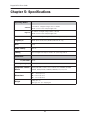
Chapter 5: Specifications
Operating Modes
Standard
16 channels of Dugan mixing at 44.1 or 48 kHz
ADAT connectors link multiple Dugan units
High-rate
8 channels of Dugan mixing at 88.2 or 96 kHz
ADAT connectors link multiple Dugan units
Shared 8 channels of Dugan mixing and 8 channels of general purpose ADAT I/O
Digital I/O
ADAT optical, 24 bit, 44.1/48 kHz (Shared mode only)
Gain
Unity
Audio Latency
0.2 ms
Linking
Up to 8 Dugan units may be linked in an optical ring network
Connectors
10/100 BASE T RJ-45
Linking and Digital I/O ADAT optical
Compatible Yamaha
Mixers
PM5D/PM5D-RH, DSP5D, M7CL, MTX5-D, LS9, DM2000, DM1000,
02R96, 01V96/01V96i, DME64N, DME24N, CL1, CL3, CL5
Dimensions
H = 4.0 cm (1.57 in)
W = 12.0 cm (4.72 in)
D = 17.6 cm (6.91 in)
Weight
160 g (5.6 oz)
0.6 kg (1 lb 5 oz) in shipping box

-
 1
1
-
 2
2
-
 3
3
-
 4
4
-
 5
5
-
 6
6
-
 7
7
-
 8
8
-
 9
9
-
 10
10
-
 11
11
-
 12
12
-
 13
13
-
 14
14
-
 15
15
-
 16
16
-
 17
17
-
 18
18
-
 19
19
-
 20
20
-
 21
21
-
 22
22
-
 23
23
-
 24
24
-
 25
25
-
 26
26
-
 27
27
-
 28
28
-
 29
29
-
 30
30
-
 31
31
-
 32
32
-
 33
33
-
 34
34
-
 35
35
-
 36
36
-
 37
37
-
 38
38
-
 39
39
-
 40
40
-
 41
41
-
 42
42
-
 43
43
-
 44
44


Dan Dugan Sound Design DUGAN-MY16 Manual de usuario
- Categoría
- Mezcladores de audio
- Tipo
- Manual de usuario
- Este manual también es adecuado para
en otros idiomas
- français: Dan Dugan Sound Design DUGAN-MY16 Manuel utilisateur
- italiano: Dan Dugan Sound Design DUGAN-MY16 Manuale utente
- English: Dan Dugan Sound Design DUGAN-MY16 User manual
- Deutsch: Dan Dugan Sound Design DUGAN-MY16 Benutzerhandbuch
- русский: Dan Dugan Sound Design DUGAN-MY16 Руководство пользователя
- Nederlands: Dan Dugan Sound Design DUGAN-MY16 Handleiding
- português: Dan Dugan Sound Design DUGAN-MY16 Manual do usuário
- dansk: Dan Dugan Sound Design DUGAN-MY16 Brugermanual
- polski: Dan Dugan Sound Design DUGAN-MY16 Instrukcja obsługi
- svenska: Dan Dugan Sound Design DUGAN-MY16 Användarmanual
- Türkçe: Dan Dugan Sound Design DUGAN-MY16 Kullanım kılavuzu
- suomi: Dan Dugan Sound Design DUGAN-MY16 Ohjekirja
- română: Dan Dugan Sound Design DUGAN-MY16 Manual de utilizare
Otros documentos
-
Yamaha PM5D El manual del propietario
-
-
-
-
-
Yamaha DM1000 Guía de instalación
-
Yamaha V96i Guía del usuario
-
-
Yamaha LS9-32 Guía de instalación
-