
www.dell.com | support.dell.com
Dell™ PowerEdge™ 6800 Systems
Information Update
信息更新
Mise à jour des informations
Aktuelle Informationen
アップデート情報
설명서 갱신본
Actualización de información


www.dell.com | support.dell.com
Dell™ PowerEdge™ 6800 Systems
Information Update

Notes, Notices, and Cautions
NOTE: A NOTE indicates important information that helps you make better use of your computer.
NOTICE: A NOTICE indicates either potential damage to hardware or loss of data and tells you how to avoid the
problem.
CAUTION: A CAUTION indicates a potential for property damage, personal injury, or death.
____________________
Information in this document is subject to change without notice.
© 2006 Dell Inc. All rights reserved.
Reproduction in any manner whatsoever without the written permission of Dell Inc. is strictly forbidden.
Trademarks used in this text: Dell, the DELL logo, and PowerEdge are trademarks of Dell Inc.; Intel is a registered trademark of Intel Corporation;
Microsoft and Windows are registered trademarks and Windows Server is a trademark of Microsoft Corporation; Red Hat is a registered trademark
of Red Hat Corporation; SUSE is a registered trademark of SUSE LINUX Products GmbH.
Other trademarks and trade names may be used in this document to refer to either the entities claiming the marks and names or their products.
Dell Inc. disclaims any proprietary interest in trademarks and trade names other than its own.
September 2006 P/N F3227 Rev. A09

Information Update 3
Information Update
This document provides information for your system on the following topics:
• Reconfiguring the system for regional power requirements
• Processor upgrades
• Adaptec SCSI Card 39160 expansion-card slot restrictions
• System start-up behavior
• Integrated NIC IPMI port functionality
• Remote Access Controller card interaction with integrated video
• System messages
• Environmental data sheets
• Removing and installing the cooling shroud
• Linux operating system information
– Booting Red Hat
®
Enterprise Linux AS (Version 4) for Intel
®
x86 with more than eight logical
processors
– Using more than eight logical processors with Red Hat Enterprise Linux (Version 4)
for Intel Extended Memory 64 Technology (Intel EM64T)
– Rebooting Red Hat Enterprise Linux AS (Version 4) for Intel EM64T
– NIC device names
• Microsoft
®
Windows Server
™
2003 installation with more than eight logical processors
• Microsoft Windows
®
2000 installation
• Console redirection—escape key sequences
CAUTION: Only trained service technicians are authorized to remove the system cover and access any of
the components inside the system. Before performing any procedure, see your Product Information Guide for
complete information about safety precautions, working inside the computer, and protecting against electrostatic
discharge.

4 Information Update
Reconfiguring the System for Regional Power Requirements
CAUTION: If you relocate a system operating in the 120–127 VAC or 200–240 VAC range to a different geographic
area, ensure that jumper CB_TYPE matches the AC line voltage range of your new location.
If the new power source is less than 120 VAC and you do not reconfigure jumper CB_TYPE for the lower voltage
power source, damage to the system power cable or the system itself may occur.
Ta bl e 1 -1
lists countries where the AC line voltage may be less than 120 V. Confirm the power source in your
particular location and reconfigure the CB_TYPE jumper if necessary.
Table 1-2 and Figure 1-1 show the settings and location of the CB_TYPE jumper.
Table 1-1. Areas Where AC Line Voltage May Be Less Than 120 V
AC Line Voltage Country
100 V Japan, Korea, Okinawa
105 V Korea
110 V Anguilla, Azores, Belgium, Belize, Bolivia, Brazil, Colombia, Curacao, Dominican
Republic, Ecuador, El Salvador, France, Guam, Guyana, Haiti, Honduras, Jamaica,
Lebanon, Panama, Peru, Philippines, Somalia, Surinam, Tahiti, Taiwan, Turkey, Virgin
Islands
115 V Aruba, Barbados, North Mariana Island, St. Pierre & Miquelon, Surinam, Tonga,
Trinidad & Tobago
Table 1-2. Power Configuration Jumper Settings
Jumper Setting Description
CB_TYPE AC line voltage is 120 V or greater*
(default) AC line voltage is less than 120 V
* This jumper is not functional for systems using a line voltage in the range of 200–240 VAC.

Information Update 5
Figure 1-1. Power Configuration Jumper Location
Processor Upgrades
If you add one or more processors to your system, ensure that all processors have the same stepping value
and the same cache size and technology. If you install processors with different speeds, they will operate
at the speed of the slowest processor.
You must install all voltage regulator modules (VRMs) included in the upgrade kit, in addition to the
processors. See "Processors" in your
Installation and Troubleshooting Guide
for details on installing processors
and VRMs.
Adaptec SCSI Card 39160 Expansion-Card Slot Restrictions
If you add an Adaptec SCSI Card 39160 to a system running the Microsoft Windows 2000 Server operating
system, and a Dell™ Remote Access Controller 4/P (DRAC 4/P) card is installed in expansion-card slot 7,
the Adaptec 39160 card must be installed in expansion-card slot 2.
Memory Test at System Start-Up
The
System Memory Testing
option in the System Setup program is disabled by default. If the option is
enabled, the system memory is tested at each system startup. Systems with large memory configurations
may take more time to complete the memory test. See your
User’s Guide
for information on the System
Setup program.

6 Information Update
System Start-Up Behavior
The following system behaviors during system start-up are normal and do not indicate a problem with the
system:
• When AC power is applied to the system, if the System Setup program’s
AC Power Recovery
option is
not set to allow the system to power up when AC power is applied, the cooling fans will spin-up briefly
and then stop. (See your
User’s Guide
for information on the System Setup program.)
• It may take 30 seconds or longer for video to display after the system is powered on.
Integrated NIC IPMI Port Functionality
If you configure the integrated NIC for Intelligent Platform Management Interface (IPMI) pass-through
traffic, and you also configure the system to boot from the network using the same IPMI port, the NIC
will not be available for management traffic during system boot. After system boot is completed, IPMI
functionality is automatically restored.
In addition, if you configure the NIC to support IPMI management traffic, the NIC driver’s Large-Send
Offload (LSO) feature will be disabled on that port.
Remote Access Controller Card Interaction With Integrated Video
If you install an optional remote access controller card for remote systems management, the system’s front
and back panel video ports will be disabled.
System Messages
Table 1-3 provides an updated list of system
status messages that the system’s front panel
LCD may
display at system start-up, if a memory error occurs. See "System Messages" in your
Installation and
Troubleshooting Guide
for additional information about system messages.

Information Update 7
Table 1-3. LCD Status Messages
Line 1
Message
Line 2
Message
Causes Corrective Actions
SYSTEM
ID
SYSTEM NAME SYSTEM ID is a unique name,
five characters or less, defined by
the user.
SYSTEM NAME is a unique
name, 16 characters or less,
defined by the user.
The system ID and name display
under the following conditions:
• The system is powered on.
• The power is off and active
POST errors are displayed.
This message is for information
only.
You can change the system ID
and name in the System Setup
program. See your User's Guide
for instructions.
E0000 OVRFLW CHECK LOG LCD overflow message.
A maximum of three error
messages can display sequentially
on the LCD. The fourth message
displays as the standard overflow
message.
Check the SEL for details on the
events.
E1000 FAIL SAFE Failsafe event. Capture the event log and see
"Getting Help" in your
Installation and Troubleshooting
Guide.
E1000 MISCONFIG Missing or improperly installed
VRMs.
See "Installing a Processor VRM"
in your Installation
and Troubleshooting Guide. If
the VRMs appear to be properly
configured and installed, see
"Getting Help" in your
Installation and Troubleshooting
Guide.
E0119 TEMP AMBIENT Ambient system temperature
is out of acceptable range.
See "Troubleshooting System
Cooling Problems" in your
Installation and Troubleshooting
Guide.
E0119 TEMP PROC # The specified processor is out
of acceptable temperature range.
See "Troubleshooting System
Cooling Problems" in your
Installation and Troubleshooting
Guide.

8 Information Update
E0119 TEMP PLANAR System board temperature is out
of acceptable temperature range.
See "Troubleshooting System
Cooling Problems" in your
Installation and Troubleshooting
Guide.
E0212 PROC VTT Processor VTT voltage is out
of acceptable voltage range.
See "Troubleshooting Power
Supplies" in your Installation
and Troubleshooting Guide.
E0212 VOLT PG n System power supply is out of
acceptable voltage range; faulty
or improperly installed power
supply.
See "Troubleshooting Power
Supplies" in your Installation
and Troubleshooting Guide.
E0212 VOLT PG n Video Video voltage is out of acceptable
voltage range.
See "Getting Help" in your
Installation and Troubleshooting
Guide.
E0212 VOLT BATT ROMB Faulty RAID battery. Replace the RAID battery.
See "Activating the Optional
Integrated RAID Controller"
in your Installation
and Troubleshooting Guide.
E0212 VOLT BATT CMOS Faulty system battery. See "Troubleshooting the System
Battery" in your Installation
and Troubleshooting Guide.
If the problem persists, see "
Getting Help" in your Installation
and Troubleshooting Guide.
E0276 PROC # STATUS Faulty or improperly installed
processor.
See "Troubleshooting the
Microprocessors" in your
Installation and Troubleshooting
Guide.
E0276 PROC # VCORE The VCORE voltage of the
specified processor is out of
acceptable range.
See "Troubleshooting the
Microprocessors" in your
Installation and Troubleshooting
Guide. If the problem still
persists, see "Getting Help"
in your Installation
and Troubleshooting Guide.
Table 1-3. LCD Status Messages (continued)
Line 1
Message
Line 2
Message
Causes Corrective Actions

Information Update 9
E0276 VRM # PG The voltage of the specified VRM
is out of acceptable range.
See "Troubleshooting the
Microprocessors" in your
Installation and Troubleshooting
Guide. If the problem still
persists, see "Getting Help"
in your Installation
and Troubleshooting Guide.
E0276 VCACHE # PG The voltage of the specified
VCACHE is out of acceptable
range.
See "Troubleshooting the
Microprocessors" in your
Installation and Troubleshooting
Guide. If the problem still
persists, see "Getting Help"
in your Installation
and Troubleshooting Guide.
E0276 PS AC CURRENT Power supply AC current is out
of acceptable range.
See "Troubleshooting Power
Supplies" in your Installation
and Troubleshooting Guide.
E0276 PS OVER CURRENT Power supply current is out
of acceptable range.
See "Troubleshooting Power
Supplies" in your Installation
and Troubleshooting Guide.
E0412 RPM FAN PS BLANK Power supply fan RPM is out
of acceptable range.
See "Troubleshooting System
Cooling Problems" in your
Installation and Troubleshooting
Guide.
E0412 RPM FAN n
FAN REDUNDANCY
LOST
Specified cooling fan is faulty,
improperly installed, or missing.
See "Troubleshooting System
Cooling Problems" in your
Installation and Troubleshooting
Guide.
E0780 PROC # CONFIG
ERR
The specified processor has
a configuration error.
See "Troubleshooting the
Microprocessors" in your
Installation and Troubleshooting
Guide.
E0780 PROC # DISABLED The specified processor is
disabled.
See "Troubleshooting the
Microprocessors" in your
Installation and Troubleshooting
Guide.
Table 1-3. LCD Status Messages (continued)
Line 1
Message
Line 2
Message
Causes Corrective Actions

10 Information Update
E0780 PROC n PRESENCE Microprocessor is not installed
in socket n.
Install a microprocessor in socket
n. See "Installing a Processor"
in your Installation
and Troubleshooting Guide.
E07F0 PROC n IERR Faulty or improperly installed
microprocessor.
See "Troubleshooting the
Microprocessors" in your
Installation and Troubleshooting
Guide.
E07FA PROC n THERMTRIP Specified microprocessor is out
of acceptable temperature range
and has halted operation.
See "Troubleshooting System
Cooling Problems" in your
Installation and Troubleshooting
Guide. If the problem persists,
ensure that the microprocessor
heat sinks are properly installed.
See " Removing a Processor"
in your Installation
and Troubleshooting Guide.
NOTE: The LCD continues to
display this message until the
system’s power cord is
disconnected and reconnected to
the AC power source, or the SEL is
cleared using either Server
Assistant or the BMC Management
Utility. See the Dell OpenManage
Baseboard Management
Controller User’s Guide for
information about these utilities.
E0876 PS n MISSING
PS n STATUS
No power available from the
specified power supply; specified
power supply is improperly
installed or faulty.
See "Troubleshooting Power
Supplies" in your Installation
and Troubleshooting Guide.
E0876 PS n PREDICTIVE Power supply voltage is out of
acceptable range; specified power
supply is improperly installed
or faulty.
See "Troubleshooting Power
Supplies" in your Installation
and Troubleshooting Guide.
E0876 PS n AC LOST
PS n AC RANGE
Power source for specified power
supply is unavailable, or out
of acceptable range.
Check the AC power source
for the specified power supply.
Table 1-3. LCD Status Messages (continued)
Line 1
Message
Line 2
Message
Causes Corrective Actions

Information Update 11
E0880 PS REDUNDANCY
LOST
Power supply redundancy has
been lost because a power supply
has been removed from the
system.
Reinstall the power supply
to restore redundancy.
E0D76 BP DRIVE n Faulty or improperly installed
hard drive or RAID controller.
See "Troubleshooting SCSI Hard
Drives," "Troubleshooting a RAID
Controller Card," and
"Troubleshooting the Integrated
RAID Controller" in your
Installation and Troubleshooting
Guide.
E0D76 1x2 Drive n The specified drive on the 1x2
backplane is faulty or improperly
installed, or the RAID controller
is faulty or improperly installed.
See "Troubleshooting SCSI Hard
Drives," "Troubleshooting a RAID
Controller Card," and
"Troubleshooting the Integrated
RAID Controller" in your
Installation and Troubleshooting
Guide.
E0D76 SCSI CONNECTOR SCSI cable is not connected. See "Troubleshooting SCSI Hard
Drives" in your Installation
and Troubleshooting Guide.
EB107 PROC BUS PERR
PROC INIT ERR
PROC PROTOCOL
ERR
Faulty or improperly installed
microprocessor or system board.
See "Troubleshooting the
Microprocessors" in your
Installation and Troubleshooting
Guide.
If the problem persists, see
"Getting Help" in your
Installation and Troubleshooting
Guide.
EB107 PROC MACHINE CHK Faulty or improperly installed
microprocessor or system board.
See "Troubleshooting the
Microprocessors" in your
Installation and Troubleshooting
Guide. If the problem persists,
see "Getting Help" in your
Installation and Troubleshooting
Guide.
EB107 PROC HOT Processor is out of acceptable
temperature range and has halted
operation.
See "Troubleshooting System
Cooling Problems" in your
Installation and Troubleshooting
Guide.
Table 1-3. LCD Status Messages (continued)
Line 1
Message
Line 2
Message
Causes Corrective Actions

12 Information Update
EB10C ECC UNCORR ERR
ECC UNCORR ERR
BANK #
Uncorrectable ECC errors have
occurred in system memory. The
affected memory bank may be
specified.
See "Troubleshooting System
Memory" in your Installation
and Troubleshooting Guide.
EB113 I/O CHANNEL CHK System I/O channel check error
has occurred.
See "Getting Help" in your
Installation and Troubleshooting
Guide.
EB113 PCI PARITY ERR PCI parity error has occurred. See "Troubleshooting Expansion
Cards" in your Installation
and Troubleshooting Guide. If
the problem persists, see "Getting
Help" in your Installation
and Troubleshooting Guide.
EB113 PCI SYSTEM ERR PCI system error has occurred. See "Troubleshooting Expansion
Cards" in your Installation
and Troubleshooting Guide. If
the problem persists, see "Getting
Help" in your Installation
and Troubleshooting Guide.
EB113 PCIE FATAL ERR Fatal PCIe error has occurred. See "Troubleshooting Expansion
Cards" in your Installation
and Troubleshooting Guide. If
the problem persists, see "Getting
Help" in your Installation
and Troubleshooting Guide.
EB113 PCIE NON
FATAL ERR
Non-fatal PCIe error has
occurred.
See "Troubleshooting Expansion
Cards" in your Installation
and Troubleshooting Guide. If
the problem persists, see "Getting
Help" in your Installation
and Troubleshooting Guide.
Table 1-3. LCD Status Messages (continued)
Line 1
Message
Line 2
Message
Causes Corrective Actions

Information Update 13
Environmental Data Sheets
For additional information about environmental measurements for specific system configurations,
see
www.dell.com/environment_datasheets
.
EB113 CHIPSET ERR An error has occurred in the
chipset.
See "Troubleshooting the
Microprocessors" in your
Installation and Troubleshooting
Guide. If the problem persists,
see "Troubleshooting Expansion
Cards" in your Installation
and Troubleshooting Guide.
If the problem still persists, see
"Getting Help" in your
Installation and Troubleshooting
Guide.
EFFF2 ROMB PRESENCE Integrated RAID controller is
activated.
Information only.
I0000 BIB BMC unable to read BIOS Initial
Block (BIB).
See "Getting Help" in your
Installation and Troubleshooting
Guide.
IB110 SBE LOG DISABLED Single-bit error log disabled. Information only.
IB110 LOGGING DISABLED BIOS logging disabled. Information only.
IB10C MEMORY SPARED Memory spare bank enabled. Information only.
IB10C MEMORY MIRRORED Memory mirroring enabled. Information only.
IB10C MEMORY RAID Memory RAID enabled. Information only.
IS000 INTRUSION System cover has been removed. Information only
NOTE: For the full name of an abbreviation or acronym used in this table, see the "Glossary"
in your User’s Guide.
Table 1-3. LCD Status Messages (continued)
Line 1
Message
Line 2
Message
Causes Corrective Actions

14 Information Update
Removing and Installing the Cooling Shroud
To remove the cooling shroud, grasp each end of the shroud and lift the shroud straight up from the system.
To install the cooling shroud, slowly lower the shroud straight down into the system and then press down on
the four icons (above the latches) until the shroud snaps into place. See Figure 1-2.
Figure 1-2. Removing and Installing the Cooling Shroud
cooling shroud
icons (4)
latches (4)

Information Update 15
Linux Operating System Information
Booting Red Hat Enterprise Linux AS (Version 4) for Intel x86 With More than Eight Logical
Processors
A system running the Red Hat Enterprise Linux AS (version 4) for Intel x86 operating system will fail
to boot if it is configured with more than eight logical processors. To work around this issue, pass the
parameter apic=bigsmp to the kernel command line at system boot. A correction for this issue will
be available in a future Red Hat Enterprise Linux Version 4 Update.
Using More than Eight Logical Processors With Red Hat Enterprise Linux (Version 4)
for Intel EM64T
A limitation in the Red Hat Enterprise Linux (version 4) for Intel EM64T operating system will cause the
operating system to use no more than eight logical processors even if more processors are present in your
system. On systems with more than eight logical processors, the Linux operating system will recognize and
report only eight processors. For more information about this limitation, see the
Red Hat Enterprise Linux 4
Update 3 Release Notes
on the Red Hat web site at
http://www.redhat.com/docs/manuals/enterprise/
.
Rebooting Red Hat Enterprise Linux AS (Version 4) for Intel EM64T
The system may hang when the message Restarting System appears while rebooting a system
running the Red Hat Enterprise Linux AS (version 4) for Intel EM64T operating system. If this occurs,
use the power button to power off the system. A correction for this issue will be available in a future
Red Hat Enterprise Linux Version 4 Update.
NIC Device Names
In a system using the Linux operating system without an optional PCI-X NIC card installed, the integrated
NICs are assigned device names
eth0
and
eth1
. However, if you install a PCI-X NIC card, the card’s NIC port
is assigned device name
eth0
(a dual-port card will be assigned device names
eth0
and
eth1)
and the
integrated NICs will be assigned subsequent numbers. The designations are assigned in the order of the PCI
bus scan.
Microsoft Windows Server 2003 Installation With More
than Eight Logical Processors
A system configured with more than eight logical processors may hang during installation of versions
of Microsoft Windows Server 2003 Standard or Enterprise Edition earlier than SP1. To avoid this issue,
temporarily disable Logical Processor in the System Setup program.
(See your
User’s Guide
for
information on the System Setup program.)

16 Information Update
Microsoft Windows 2000 Installation
Installation of Microsoft Windows 2000 Server or Microsoft Windows 2000 Advance Server is
not
supported
on PowerEdge 6800 systems featuring dual-core processors with L3 cache.
NOTE:
Installation of Microsoft Windows 2000 Server or Microsoft Windows 2000 Advanced Server is
supported on PowerEdge 6800 systems featuring single-core processors (with or without L3 cache)
and dual-core processors with L2 cache only.
The processor type can be obtained by one of the following methods:
• Check your system purchase order details.
• Check the system startup screen.
• Check
CPU Information
in the system setup program.
Console Redirection—Escape Key Sequences
The following table updates the escape key sequences for function keys in the "Using Console
Redirection" section of your User’s Guide.
Table 1-4. Escape Sequences for Function Keys
Key(s) Supported Sequence
<F1> <Esc><1>
<F2> <Esc><2>
<F3> <Esc><3>
<F4> <Esc><4>
<F5> <Esc><5>
<F6> <Esc><6>
<F7> <Esc><7>
<F8> <Esc><8>
<F9> <Esc><9>
<F10> <Esc><0>
<F12> <Esc><@>

www.dell.com | support.dell.com
Dell
™
PowerEdge
™
6800 系统
信息更新

注、注意和警告
注:注表示可以帮助您更好地使用计算机的重要信息。
注意:注意表示可能会损坏硬件或导致数据丢失,并告诉您如何避免此类问题。
警告:警告表示可能会导致财产损失、人身伤害甚至死亡。
____________________
本文件中的信息如有更改,恕不另行通知。
© 2006 Dell Inc.
版权所有,翻印必究。
未经
Dell Inc.
书面许可,严禁以任何形式进行复制。
本文中使用的商标:
Dell
、
DELL
徽标和
PowerEdge
是
Dell Inc.
商标;
Intel
是
Intel Corporation
的注册商标;
Microsoft
和
Windows
是
Microsoft Corporation
的注册商标,
Windows Server
是
Microsoft Corporation
的商标;
Red Hat
是
Red Hat Corporation
的注册商
标;
SUSE
是
SUSE LINUX Products GmbH
的注册商标。
本文件中述及的其它商标和产品名称是指拥有相应商标和名称的公司或其制造的产品。
Dell Inc.
对本公司的商标和产品名称之外
的其它商标和产品名称不拥有任何专有权。
2006
年
9
月
P/N F3227
修订版
A09

信息更新 19
信息更新
本说明文件针对您的系统提供了有关以下主题的信息:
•
针对地区性的电源要求重新配置系统
•
处理器升级
•
Adaptec SCSI Card 39160
扩充卡插槽限制
•
系统启动行为
•
集成
NIC IPMI
端口功能
•
远程访问控制器卡与集成视频的相互影响
•
系统信息
•
环境数据表
•
卸下和安装冷却通风罩
•
Linux
操作系统信息
–
当系统配备
8
个以上逻辑处理器时引导适用于
Intel
®
x86
的
Red Hat
®
Enterprise Linux AS
(第
4
版)
–
对适用于
Intel 64
位扩展内存技术
(Intel EM64T)
的
Red Hat Enterprise Linux
(第
4
版)
使用多于八个的逻辑处理器
–
重新引导用于
Intel 64
位扩展内存技术
(Intel EM64T)
的
Red Hat Enterprise Linux AS
(第
4
版)
–
NIC
设备名称
•
在多于八个逻辑处理器时安装
Microsoft
®
Windows Server
™
2003
•
Microsoft Windows
®
2000
安装
•
控制台重定向
-
按键转义序列
警告:只有经过培训的维修技术人员才有权卸下主机盖并拆装系统内部的任何组件。在执行任何过程之
前,请参阅《产品信息指南》,获取有关安全预防措施、拆装计算机内部组件以及防止静电释放的完整
信息。

20 信息更新
针对地区性的电源要求重新配置系统
警告:如果将工作在
120-127 VAC
或
200-240 VAC
范围内的系统重新部署到另一个地区,应确保跳线
CB_TYPE
与新位置的交流线电压范围相符。
如果新电源低于
120 VAC
并且没有针对较低电压电源重新配置跳线
CB_TYPE
,则可能会导致系统电源线或
系统本身损坏。
表
1-1
列出了交流线电压可能低于
120 V
的国家或地区。请确认您所在的特定位置的电源,
并根据需要重新配置
CB_TYPE
跳线。
表
1-2
和图
1-1
说明了
CB_TYPE
跳线的设置和位置。
表
1-1.
交流线电压可能低于
120 V
的地区
交流线电压 国家或地区
100 V
日本、韩国、冲绳群岛
105 V
韩国
110 V
安圭拉、亚述尔群岛、比利时、伯利兹、玻利维亚、巴西、哥伦比亚、
库拉索、多米尼加共和国、厄瓜多尔、萨尔瓦多、法国、关岛、圭亚那、
海地、洪都拉斯、牙买加、黎巴嫩、巴拿马、秘鲁、菲律宾、索马里、
苏里南、塔希提岛、台湾、土尔其、维尔京群岛
115 V
阿鲁巴、巴巴多斯、北马里亚纳群岛、圣皮埃尔和密克隆群岛、苏里南、
汤加、特立尼达和多巴哥
表
1-2.
电源配置跳线设置
跳线 设置 说明
CB_TYPE
交流线电压为
120 V
或更高
*
(默认设置) 交流线电压低于
120 V
* 如果系统使用的线电压在 200-240 VAC 范围内,此跳线不起作用。

信息更新 21
图
1-1.
电源配置跳线位置
处理器升级
如果将一个或多个处理器添加到系统中,应确保所有处理器均具有相同的步进值和相同的缓存大小和
技术。如果安装的处理器具有不同速率,它们将以最慢处理器的速率工作。
除了处理器之外,还必须安装升级套件中附带的所有稳压器模块
(VRM)
。有关安装处理器和
VRM
的
详情,请参阅
《安装与故障排除指南》
中的“处理器”。
Adaptec SCSI Card 39160
扩充卡插槽限制
如果将
Adaptec SCSI Card 39160
添加到运行
Microsoft Windows 2000 Server
操作系统的系统中,并且
Dell
™
远程访问控制器
4/P (DRAC 4/P)
卡安装在扩充卡插槽
7
中,则
Adaptec 39160
卡必须安装在扩充
卡插槽
2
中。
系统启动时的内存测试
系统设置程序中的
System Memory Testing
(系统内存测试)选项默认为禁用。如果启用该选项,系统
每次启动时都会测试系统内存。较大内存配置的系统可能需要更多时间来完成内存测试。有关系统设
置程序的信息,请参阅
《用户指南》
。

22 信息更新
系统启动行为
在系统启动期间,以下系统行为属于正常现象,并不表示系统有问题。
•
当交流电源施加在系统上时,如果系统设置程序的
AC Power Recovery
(交流电源恢复)选项没有
设为允许系统在交流电源接通时启动,冷却风扇将会短暂地转动,然后停止。(有关系统设置程序
的信息,请参阅
《用户指南》
。)
•
在系统通电之后,可能需要
30
秒或更长时间才能显示视频。
集成
NIC IPMI
端口功能
如果将集成
NIC
配置为用于传送智能平台管理接口(
IPMI
,
Intelligent Platform Management
Interface
)直通流量,同时还将系统配置为使用同一个
IPMI
端口通过网络引导,则在系统引导期间,
NIC
将无法用于传送管理流量。系统引导之后,
IPMI
功能会自动恢复。
此外,如果将
NIC
配置为支持
IPMI
管理流量,则
NIC
驱动程序的大量传送卸载
(
LSO
,
Large-Send Offload
)功能将在该端口上禁用。
远程访问控制器卡与集成视频的相互影响
如果安装可选的远程访问控制器卡以用于远程系统管理,则系统前面板和后面板的视频端口
将被禁用。
系统信息
表
1-3
提供了系统状态信息的更新列表,如果系统启动时发生内存错误,系统前面板
LCD
会显示该信
息。有关系统信息的其它信息,请参阅
《安装与故障排除指南》
中的“系统信息”。

信息更新 23
表
1-3. LCD
状态信息
第
1
行
信息
第
2
行
信息
原因 纠正措施
SYSTEM
ID
SYSTEM NAME
SYSTEM ID(系统标识)是一
个少于或等于
5
个字符的唯
一名称,由用户定义。
SYSTEM NAME(系统名称)
是一个少于或等于
16
个字符的
唯一名称,由用户定义。
如果出现以下情况,将会显
示系统标识和名称:
• 系统已开机。
• 电源已关闭,并且显示活动
POST
错误。
此信息仅供参考。
您可以在系统设置程序中更改系
统标识和名称。有关说明,
请参阅《用户指南》。
E0000 OVRFLW CHECK LOG
LCD
溢出信息。
LCD
上最多可连续显示三
则错误信息。第四则信息将
作为标准溢出信息显示。
查看
SEL
以了解事件的详
细信息。
E1000 FAIL SAFE
故障保护事件。 获取事件日志,并请参阅
《安装与故障排除指南》中的
“获得帮助”。
E1000 MISCONFIG
缺少
VRM
或
VRM
安装
不正确。
请参阅《安装与故障排除指南》
中的“安装处理器
VRM
”。
如果
VRM
已正确配置和安装,
请参阅《安装与故障排除指南》
中的“获得帮助”。
E0119 TEMP AMBIENT
系统环境温度已超出可接受
的范围。
请参阅《安装与故障排除指南》
中的“排除系统冷却问题”。
E0119 TEMP PROC #
指定的处理器已超出可接受
的温度范围。
请参阅《安装与故障排除指南》
中的“排除系统冷却问题”。
E0119 TEMP PLANAR
系统板温度已超出可接受的
温度范围。
请参阅《安装与故障排除指南》
中的“排除系统冷却问题”。
E0212 PROC VTT
处理器
VTT
电压已超出可接受
的电压范围。
请参阅《安装与故障排除指南》
中的“排除电源设备故障”。
E0212 VOLT PG n
系统电源设备已超出可接受的
电压范围;电源设备出现故
障或安装不正确。
请参阅《安装与故障排除指南》
中的“排除电源设备故障”。

24 信息更新
E0212 VOLT PG n Video
视频电压已超出可接受的电
压范围。
请参阅《安装与故障排除指南》
中的“获得帮助”。
E0212 VOLT BATT ROMB
RAID
电池出现故障。 更换
RAID
电池。请参阅
《安装与故障排除指南》中的
“激活可选的集成
RAID
控制器”。
E0212 VOLT BATT CMOS
系统电池出现故障。 请参阅《安装与故障排除指南》
中的“排除系统电池故障”。
如果问题仍然存在,请参阅
《安装与故障排除指南》中的
“获得帮助”。
E0276 PROC # STATUS
处理器出现故障或安装不正确。 请参阅《安装与故障排除指南》
中的“排除微处理器故障”。
E0276 PROC # VCORE
指定处理器的
VCORE
电压
已超出可接受的范围。
请参阅《安装与故障排除指南》
中的“排除微处理器故障”。
如果问题仍然存在,请参阅
《安装与故障排除指南》中的
“获得帮助”。
E0276 VRM # PG
指定
VRM
的电压已超出
可接受的范围。
请参阅《安装与故障排除指南》
中的“排除微处理器故障”。
如果问题仍然存在,请参阅
《安装与故障排除指南》中的
“获得帮助”。
E0276 VCACHE # PG
指定
VCACHE
的电压已
超出可接受的范围。
请参阅《安装与故障排除指南》
中的“排除微处理器故障”。
如果问题仍然存在,请参阅
《安装与故障排除指南》中的
“获得帮助”。
E0276 PS AC CURRENT
电源设备交流电流已超出
可接受的范围。
请参阅《安装与故障排除指南》
中的“排除电源设备故障”。
E0276 PS OVER CURRENT
电源设备电流已超出可接
受的范围。
请参阅《安装与故障排除指南》
中的“排除电源设备故障”。
E0412 RPM FAN PS BLANK
电源设备风扇
RPM
已超出
可接受的范围。
请参阅《安装与故障排除指南》
中的“排除系统冷却问题”。
表
1-3. LCD
状态信息
(续)
第
1
行
信息
第
2
行
信息
原因 纠正措施

信息更新 25
E0412 RPM FAN n
FAN REDUNDANCY
LOST
指定的冷却风扇出现故障、
安装不正确或未安装。
请参阅《安装与故障排除指南》
中的“排除系统冷却问题”。
E0780 PROC # CONFIG
ERR
指定的处理器出现配置错误。 请参阅《安装与故障排除指南》
中的“排除微处理器故障”。
E0780 PROC # DISABLED
禁用了指定的处理器。 请参阅《安装与故障排除指南》
中的“排除微处理器故障”。
E0780 PROC n PRESENCE
微处理器未安装在插槽
n
中。 在插槽
n
中安装微处理器。
请参阅《安装与故障排除指南》
中的“安装处理器”。
E07F0 PROC n IERR
微处理器出现故障或安装
不正确。
请参阅《安装与故障排除指南》
中的“排除微处理器故障”。
E07FA PROC n THERMTRIP
指定的微处理器超出可接
受的温度范围,已停止操作。
请参阅《安装与故障排除指南》
中的“排除系统冷却问题”。
如果问题仍然存在,请确保微处
理器散热器已正确安装。请参阅
《安装与故障排除指南》中的
“卸下处理器”。
注:
LCD 会继续显示该信息,
直到系统的电源线与交流电源断
开连接然后重新连接,或使用
Server Assistant 或 BMC
Management Utility 清除 SEL。
有关这些公用程序的信息,
请参阅 《Dell OpenManage 底板
管理控制器用户指南》。
E0876 PS n MISSING
PS n STATUS
指定的电源设备未提供电源;
指定的电源设备安装不正确
或出现故障。
请参阅《安装与故障排除指南》
中的“排除电源设备故障”。
E0876 PS n PREDICTIVE
电源设备的电压已超出可接
受的范围;指定的电源设备
安装不正确或出现故障。
请参阅《安装与故障排除指南》
中的“排除电源设备故障”。
E0876 PS n AC LOST
PS n AC RANGE
指定的电源设备的电源没有电,
或已超出可接受的范围。
请检查指定的电源设备的交
流电源。
E0880 PS REDUNDANCY
LOST
由于已从系统中卸下电源设备,
因此缺少了冗余电源设备。
重新安装电源设备以恢复冗余。
表
1-3. LCD
状态信息
(续)
第
1
行
信息
第
2
行
信息
原因 纠正措施

26 信息更新
E0D76 BP DRIVE n
硬盘驱动器或
RAID
控制器
出现故障或安装不正确。
请参阅《安装与故障排除指南》
中的“排除
SCSI
硬盘驱动器故
障”、“排除
RAID
控制器卡故
障”或“排除集成
RAID
控制器
故障”。
E0D76 1x2 DRIVE n
1x2
背板上的指定驱动器出现
故障或安装不正确,或
RAID
控制器出现故障或安装不正确。
请参阅《安装与故障排除指南》
中的“排除
SCSI
硬盘驱动器故
障”、“排除
RAID
控制器卡故
障”或“排除集成
RAID
控制器
故障”。
E0D76 SCSI CONNECTOR
SCSI
电缆断开。 请参阅《安装与故障排除指南》
中的“排除
SCSI
硬盘驱动
器故障”。
EB107 PROC BUS PERR
PROC INIT ERR
PROC PROTOCOL
ERR
微处理器或主板出现故障或
安装不正确。
请参阅《安装与故障排除指南》
中的“排除微处理器故障”。
如果问题仍然存在,请参阅
《安装与故障排除指南》中的
“获得帮助”。
EB107 PROC MACHINE CHK
微处理器或主板出现故障或
安装不正确。
请参阅《安装与故障排除指南》
中的“排除微处理器故障”。
如果问题仍然存在,请参阅
《安装与故障排除指南》中的
“获得帮助”。
EB107 PROC HOT
处理器超出可接受的温度范围,
已停止操作。
请参阅《安装与故障排除指南》
中的“排除系统冷却问题”。
EB10C ECC UNCORR ERR
ECC UNCORR ERR
BANK #
系统内存中发生不可修复的
ECC
错误。可能指定了受影
响的内存组。
请参阅《安装与故障排除指南》
中的“排除系统内存故障”。
EB113 I/O CHANNEL CHK
出现系统
I/O
信道检查错误。
请参阅《安装与故障排除指南》
中的“获得帮助”。
EB113 PCI PARITY ERR
出现了
PCI
奇偶校验错误。 请参阅《安装与故障排除指南》
中的“排除扩充卡故障”。
如果问题仍然存在,请参阅
《安装与故障排除指南》中的
“获得帮助”。
表
1-3. LCD
状态信息
(续)
第
1
行
信息
第
2
行
信息
原因 纠正措施

信息更新 27
EB113 PCI SYSTEM ERR
出现了
PCI
系统错误。 请参阅《安装与故障排除指南》
中的“排除扩充卡故障”。
如果问题仍然存在,请参阅
《安装与故障排除指南》中的
“获得帮助”。
EB113 PCIE FATAL ERR
出现了严重的
PCIe
错误。 请参阅《安装与故障排除指南》
中的“排除扩充卡故障”。
如果问题仍然存在,请参阅
《安装与故障排除指南》中的
“获得帮助”。
EB113 PCIE NON FATAL
ERR
出现了非严重的
PCIe
错误。 请参阅《安装与故障排除指南》
中的“排除扩充卡故障”。
如果问题仍然存在,请参阅
《安装与故障排除指南》中的
“获得帮助”。
EB113 CHIPSET ERR
芯片组出现错误。 请参阅《安装与故障排除指南》
中的“排除微处理器故障”。
如果问题仍然存在,请参阅
《安装与故障排除指南》中的
“排除扩充卡故障”。如果问题
仍然存在,请参阅《安装与故障
排除指南》中的“获得帮助”。
EFFF2 ROMB PRESENCE
已激活集成的
RAID
控制器。 仅供参考。
I0000 BIB
BMC
无法读取
BIOS
初始块
(BIB)
。
请参阅《安装与故障排除指南》
中的“获得帮助”。
IB110 SBE LOG DISABLED
已禁用单一位错误日志。 仅供参考。
IB110 LOGGING DISABLED
已禁用
BIOS
日志记录。 仅供参考。
IB10C MEMORY SPARED
内存备用记忆库已启用。 仅供参考。
IB10C MEMORY MIRRORED
内存镜像功能已启用。 仅供参考。
IB10C MEMORY RAID
已启用内存
RAID
。 仅供参考。
IS000 INTRUSION
主机盖被卸下。 仅供参考
注:
有关本表中缩写词或缩略词的全名,请参阅 《用户指南》中的 “词汇表”。
表
1-3. LCD
状态信息
(续)
第
1
行
信息
第
2
行
信息
原因 纠正措施


信息更新 29
Linux
操作系统信息
当系统配备
8
个以上逻辑处理器时引导适用于
Intel x86
的
Red Hat Enterprise
Linux AS
(第
4
版)
如果一台运行适用于
Intel x86
的
Red Hat Enterprise Linux AS
(第
4
版)操作系统的系统配置了
8
个以
上的逻辑处理器,系统将无法引导。要解决这一问题,请在系统引导时将参数
apic=bigsmp
传递到
内核命令行。在将来的
Red Hat Enterprise Linux
第
4
版更新中将提供此问题的修正。
对适用于
Intel EM64T
的
Red Hat Enterprise Linux
(第
4
版)使用多于八个的逻辑处理器
适用于
Intel EM64T
的
Red Hat Enterprise Linux
(第
4
版)操作系统存在一个限制,该限制导致操作
系统所使用的逻辑处理器不得超过八个,即使系统中的处理器多于八个也是如此。对于配备的逻辑处
理器超过八个的系统,此
Linux
操作系统将只识别和报告八个处理器。有关这一限制的详情,请参阅
Red Hat
网站
http://www.redhat.com/docs/manuals/enterprise/
上的
Red Hat Enterprise Linux 4
更新
3
版
本注释。
重新引导适用于
Intel EM64T
的
Red Hat Enterprise Linux AS
(第
4
版)
当重新引导运行用于
Intel EM64T
的
Red Hat Enterprise Linux AS
(第
4
版)操作系统的系统时,
在出现信息
Restarting System
(重新启动系统)
时,该系统可能会挂起。如果出现这种情况,
请使用电源按钮关闭系统。在将来的
Red Hat Enterprise Linux
第
4
版更新中将提供此问题的修正。
NIC
设备名称
在使用
Linux
操作系统且没有安装可选
PCI-X NIC
卡的系统中,为集成
NIC
分配的设备名称是
eth0
和
eth1
。但是,如果安装
PCI-X NIC
卡,则为该卡的
NIC
端口分配设备名称
eth0
(将为双端口卡
分配设备名称
eth0
和
eth1
)
,而为集成
NIC
分配后续编号。这些指定名称按
PCI
总线扫描序
列分配。
在多于八个逻辑处理器时安装
Microsoft Windows Server 2003
在安装低于
SP1
的
Microsoft Windows Server 2003
标准版或企业版时,配置八个以上逻辑处理器的系统
可能会挂起。要避免这一问题,请在系统设置程序中暂时禁用
Logical Processor
(逻辑处理器)。
(有关系统设置程序的详细信息,请参阅
《用户指南》
。)

30 信息更新
Microsoft Windows 2000
安装
在配备双核处理器(带
L3
高速缓存)的
PowerEdge 6800
系统上,不支持安装
Microsoft Windows 2000
Server
或
Microsoft Windows 2000 Advance Server
。
注:
如果
PowerEdge 6800
系统配备的是单核心处理器(带或不带
L3
高速缓存)和只带
L2
高速缓
存的双核处理器,则支持安装
Microsoft Windows 2000 Server
或
Microsoft Windows 2000
Advanced Server
。
可以通过以下方法之一获得处理器类型:
•
检查您的系统采购订单详细信息。
•
检查系统启动屏幕。
•
在系统设置程序中检查
CPU Information
(
CPU
信息)。
控制台重定向
-
按键转义序列
下表更新了
《用户指南》
的“使用控制台重定向”部分中的功能键的按键转义序列。
表
1-4.
功能键的转义序列
按键 支持的序列
<F1> <Esc><1>
<F2> <Esc><2>
<F3> <Esc><3>
<F4> <Esc><4>
<F5> <Esc><5>
<F6> <Esc><6>
<F7> <Esc><7>
<F8> <Esc><8>
<F9> <Esc><9>
<F10> <Esc><0>
<F12> <Esc><@>
F3227eb9.fm Page 30 Tuesday, September 5, 2006 11:14 AM

www.dell.com | support.dell.com
Systèmes Dell™ PowerEdge™ 6800
Mise à jour des informations

Remarques, avis et précautions
REMARQUE : une REMARQUE indique des informations importantes qui peuvent vous aider à mieux utiliser
votre ordinateur.
AVIS : un AVIS vous avertit d'un risque de dommage matériel ou de perte de données et vous indique comment éviter
le problème.
PRÉCAUTION : une PRÉCAUTION indique un risque potentiel d'endommagement du matériel, de blessure corporelle
ou de mort.
____________________
Les informations contenues dans ce document peuvent être modifiées sans préavis.
© 2006 Dell Inc. Tous droits réservés.
La reproduction de ce document de quelque manière que ce soit sans l'autorisation écrite de Dell Inc. est strictement interdite.
Marques utilisées dans ce document : Dell, le logo DELL et PowerEdge sont des marques de Dell Inc. ; Intel est une marque déposée de Intel
Corporation ; Microsoft et Windows sont des marques déposées de Microsoft Corporation ; Windows Server est une marque de Microsoft
Corporation ; Red Hat est une marque déposée de Red Hat Corporation ; SUSE est une marque déposée de SUSE LINUX Products GmbH.
Tous les autres noms de marques et marques commerciales utilisés dans ce document se rapportent aux sociétés propriétaires des marques et
des noms de ces produits. Dell Inc. décline tout intérêt dans l'utilisation des marques déposées et des noms de marques ne lui appartenant pas.
Septembre 2006 P/N F3227 Rev. A09

Mise à jour des informations 33
Mise à jour des informations
Ce document traite des sujets suivants :
• Reconfiguration du système en fonction de normes électriques locales
• Mises à niveau des processeurs
• Restriction liée à l'installation de la carte SCSI 39160 Adaptec dans un logement d'extension
• Comportement du système au démarrage
• Port IPMI intégré du NIC
• Interaction de la carte RAC avec la vidéo intégrée
• Messages du système
• Feuilles techniques sur l'environnement système
• Installation et retrait du carénage de ventilation
• Informations concernant le système d'exploitation Linux
– Démarrage de Red Hat
®
Enterprise Linux AS (version 4) pour Intel
®
x86 sur les systèmes
comprenant plus de huit processeurs logiques
– Utilisation de Red Hat Enterprise Linux (version 4) pour Intel EM64T avec plus
de huit processeurs logiques
– Redémarrage de Red Hat Enterprise Linux AS (version 4) pour Intel EM64T
– Noms de périphériques NIC
• Installation de Microsoft
®
Windows Server
™
2003 sur des systèmes équipés de plus
de huit processeurs logiques
• Installation de Microsoft Windows
®
2000
• Redirection de console : séquences de touches utilisant la touche Échap
PRÉCAUTION : seuls les techniciens de maintenance qualifiés sont habilités à retirer le capot du système pour
accéder aux composants internes. Avant de commencer toute intervention, consultez le Guide d'informations sur
le produit pour obtenir des informations détaillées sur les consignes de sécurité, les interventions dans
l'ordinateur et la protection contre les décharges électrostatiques.

34 Mise à jour des informations
Reconfiguration du système en fonction de normes électriques
locales
PRÉCAUTION : si vous déplacez le système d'une région utilisant une alimentation de 120–127 ou 200–240 V.c.a
vers une autre zone géographique, vérifiez que le cavalier CB_TYPE est sur la position appropriée pour la région
de destination. Si vous ne réglez pas ce cavalier sur la tension la plus basse alors que la nouvelle source
d'alimentation utilise une tension inférieure à 120 V.c.a, vous risquez d'endommager le système ou le cordon
d'alimentation.
Le tableau 1-1
répertorie les pays pouvant utiliser une tension inférieure à 120 V. Vérifiez la tension utilisée
dans la région où vous vous trouvez et modifiez la position du cavalier CB_TYPE si nécessaire.
Le tableau 1-2 et la figure 1-1 présentent les réglages et l'emplacement du cavalier CB_TYPE.
Tableau 1-1. Régions dans lesquelles la tension d'alimentation peut être inférieure à 120 V
Tension
d'alimentation
en CA.
Pays
100 V Japon, Corée, Okinawa
105 V Corée
110 V Anguilla, Açores, Belgique, Belize, Bolivie, Brésil, Colombie, Curaçao, République
dominicaine, Équateur, France, Guam, Guyana, Haïti, Honduras, Îles vierges, Jamaïque,
Liban, Panama, Pérou, Philippines, Salvador, Somalie, Surinam, Tahiti, Taiwan, Turquie
115 V Aruba, Barbade, Île North Mariana, St. Pierre & Miquelon, Surinam, Tonga,
Trinidad & Tobago
Tableau 1-2. Réglages du cavalier pour la configuration de l'alimentation
Cavalier Paramètre Description
CB_TYPE Alimentation en 120 V ou supérieure*
(par défaut) Alimentation en 120 V ou inférieure
* Ce cavalier ne fonctionne pas sur les systèmes utilisant une tension d'alimentation de 200-240 V.c.a.

Mise à jour des informations 35
Figure 1-1. Emplacement du cavalier de configuration de l'alimentation
Mises à niveau des processeurs
Si vous ajoutez un ou plusieurs processeurs au système, vérifiez que tous les processeurs ont le même
numéro de série type (stepping) et utilisent une mémoire cache de même taille et basée sur la même
technologie. Si les processeurs ont des vitesses différentes, ils fonctionneront tous à la vitesse du processeur
le plus lent.
En plus des processeurs, vous devez installer tous les modules régulateurs de tension (VRM) inclus dans le
kit de mise à niveau. Pour plus d'informations sur l'installation des processeurs et des VRM, voir la section
“Processeurs” dans le
Guide d'installation et de dépannage
.
Restriction liée à l'installation de la carte SCSI 39160 Adaptec
dans un logement d'extension
Si vous utilisez un système Microsoft Windows 2000 Server sur lequel un contrôleur DRAC (Dell™ Remote
Access Controller) 4/P est installé dans le logement 7, la carte SCSI 39160 Adaptec doit être placée dans le
logement 2.

36 Mise à jour des informations
Test de la mémoire au démarrage du système
Par défaut, l'option
System Memory Testing
(Test de la mémoire système) est désactivée dans le programme
de configuration du système. Si elle est activée, la mémoire système est testée à chaque démarrage. Ce test
peut durer plus longtemps sur les systèmes disposant d'une quantité de mémoire importante. Consultez le
Guide d'utilisation
pour plus d'informations sur le programme de configuration du système.
Comportement du système au démarrage
Les événements suivants constatés au démarrage du système sont normaux et ne signalent pas la présence
d'un incident :
• Lorsque le système est alimenté en CA, si l'option
AC Power Recovery
(Retour de l'alimentation
secteur) du programme de configuration du système n'est pas configurée pour que le système soit mis
sous tension lors de son branchement sur le secteur, les ventilateurs se mettent en marchent
brièvement puis s'arrêtent. Consultez le
Guide d'utilisation
pour plus d'informations sur le programme
de configuration du système.
• Le délai nécessaire pour l'affichage vidéo peut prendre plus de trente secondes après la mise sous
tension du système.
Port IPMI intégré du NIC
Si vous configurez le NIC intégré pour le trafic IPMI (Intelligent Platform Management Interface) et si vous
configurez également le système pour qu'il démarre à partir du réseau en utilisant le même port IPMI,
le NIC ne peut pas traiter le trafic de gestion au démarrage du système. Une fois le démarrage effectué,
la fonctionnalité IPMI est automatiquement restaurée.
En outre, si vous configurez le NIC pour la prise en charge du trafic de gestion IPMI, la fonction LSO
(Large-Send Offload) du pilote du NIC est désactivée sur le port correspondant.
Interaction de la carte RAC avec la vidéo intégrée
Si vous installez une carte RAC pour la gestion des systèmes distants, les ports vidéo avant et arrière
du système sont désactivés.

Mise à jour des informations 37
Messages système
Le
tableau 1-3 contient la liste à jour des
messages d'état qui peuvent s'afficher sur l'écran LCD du
panneau avant
si une erreur mémoire se produit au démarrage du système. Pour plus d'informations sur
les messages du système, voir la section “Messages système” dans le
Guide d'installation et de dépannage
.
Tableau 1-3. Messages d'état affichés sur l'écran LCD
Message sur
la ligne 1
Message sur la ligne 2 Causes Actions correctrices
ID DU
SYSTÈME
NOM DU SYSTÈME ID DU SYSTÈME est un nom
unique, contenant un maximum
de cinq caractères définis par
l'utilisateur.
NOM DU SYSTÈME est un nom
unique, contenant un maximum
de 16 caractères définis par
l'utilisateur.
L'ID et le nom du système
s'affichent dans les cas suivants :
• Le système est sous tension.
• Le système est hors tension
et des erreurs POST sont
affichées.
Ce message est affiché
uniquement pour information.
Vous pouvez modifier
l'identificateur et le nom du
système dans le programme
de configuration du système.
Consultez le document User's
Guide (Guide d'utilisation)
pour obtenir des instructions.
E0000 OVRFLW CHECK LOG Les messages à afficher dépassent
la capacité de l'écran LCD.
L'écran LCD ne peut afficher que
trois messages d'erreur à la suite.
Le quatrième message indique
que la capacité de l'écran est
à son maximum.
Vérifiez le journal d'événements
du système pour plus de détails.
E1000 FAIL SAFE Événement Failsafe. Faites une copie du journal
d'événements et reportez-vous
à la section “Getting Help”
(Obtention d'aide) du document
Installation and Troubleshooting
Guide (Guide d'installation
et de dépannage).

38 Mise à jour des informations
E1000 MISCONFIG Des modules VRM sont mal
installés ou manquants.
Voir “Installing a Processor VRM”
(Installation d'un module VRM
de processeur), dans le document
Installation and Troubleshooting
Guide (Guide d'installation et de
dépannage). Si les modules VRM
semblent installés et configurés
correctement, reportez-vous à la
section “Getting Help”
(Obtention d'aide) du document
Installation and Troubleshooting
Guide (Guide d'installation et de
dépannage).
E0119 TEMP AMBIENT La température ambiante du
système est en dehors des limites
autorisées.
Voir “Troubleshooting System
Cooling Problems” (Dépannage
des incidents de refroidissement
du système), dans le document
Installation and Troubleshooting
Guide (Guide d'installation et
de dépannage).
E0119 TEMP PROC # La température du processeur
spécifié est en dehors des limites
autorisées.
Voir “Troubleshooting System
Cooling Problems” (Dépannage
des incidents de refroidissement
du système), dans le document
Installation and Troubleshooting
Guide (Guide d'installation et
de dépannage).
E0119 TEMP PLANAR La température de la carte
système est en dehors des
limites autorisées.
Voir “Troubleshooting System
Cooling Problems” (Dépannage
des incidents de refroidissement
du système), dans le document
Installation and Troubleshooting
Guide (Guide d'installation et
de dépannage).
E0212 PROC VTT La tension VTT du processeur
spécifié est en dehors des
limites autorisées.
Voir “Troubleshooting Power
Supplies” (Dépannage des blocs
d'alimentation), dans le
document Installation and
Troubleshooting Guide (Guide
d'installation et de dépannage).
Tableau 1-3. Messages d'état affichés sur l'écran LCD (suite)
Message sur
la ligne 1
Message sur la ligne 2 Causes Actions correctrices

Mise à jour des informations 39
E0212 VOLT PG n L'alimentation du système a
dépassé la plage de tension
autorisée ; installation incorrecte
ou panne d'alimentation.
Voir “Troubleshooting Power
Supplies” (Dépannage des blocs
d'alimentation), dans le
document Installation and
Troubleshooting Guide (Guide
d'installation et de dépannage).
E0212 VOLT PG n Video La tension d'alimentation de
la carte graphique est en dehors
des limites autorisées.
Voir “Getting Help” (Obtention
d'aide), dans le document
Installation and Troubleshooting
Guide (Guide d'installation et
de dépannage).
E0212 VOLT BATT ROMB La pile RAID est défectueuse. Remplacez la pile RAID.
Voir “Activating the Optional
Integrated RAID Controller”
(Activation du contrôleur RAID
intégré en option), dans le
document Installation and
Troubleshooting Guide (Guide
d'installation et de dépannage).
E0212 VOLT BATT CMOS La pile système est défectueuse. Voir “Troubleshooting the System
Battery” (Dépannage de la pile du
système), dans le document
Installation and Troubleshooting
Guide (Guide d'installation et de
dépannage). Si l'incident persiste,
voir “Getting Help” (Obtention
d'aide), dans le document
Installation and Troubleshooting
Guide (Guide d'installation et
de dépannage).
E0276 PROC # STATUS Le processeur est défectueux
ou mal installé.
Voir “Troubleshooting the
Microprocessors” (Dépannage
des microprocesseurs), dans le
document Installation and
Troubleshooting Guide (Guide
d'installation et de dépannage).
Tableau 1-3. Messages d'état affichés sur l'écran LCD (suite)
Message sur
la ligne 1
Message sur la ligne 2 Causes Actions correctrices

40 Mise à jour des informations
E0276 PROC # VCORE La tension VCORE du processeur
spécifié est en dehors des limites
autorisées.
Voir “Troubleshooting the
Microprocessors” (Dépannage
des microprocesseurs), dans
le document Installation and
Troubleshooting Guide (Guide
d'installation et de dépannage).
Si l'incident persiste, voir
“Getting Help” (Obtention
d'aide), dans le document
Installation and Troubleshooting
Guide (Guide d'installation et
de dépannage).
E0276 VRM # PG La tension des modules VRM
est en dehors des limites
autorisées.
Voir “Troubleshooting the
Microprocessors” (Dépannage
des microprocesseurs), dans le
document Installation and
Troubleshooting Guide (Guide
d'installation et de dépannage).
Si l'incident persiste, voir
“Getting Help” (Obtention
d'aide), dans le document
Installation and Troubleshooting
Guide (Guide d'installation et
de dépannage).
E0276 VCACHE # PG La tension du VCACHE spécifié
est en dehors des limites
autorisées.
Voir “Troubleshooting the
Microprocessors” (Dépannage
des microprocesseurs), dans
le document Installation and
Troubleshooting Guide (Guide
d'installation et de dépannage).
Si l'incident persiste, voir
“Getting Help” (Obtention
d'aide), dans le document
Installation and Troubleshooting
Guide (Guide d'installation
et de dépannage).
Tableau 1-3. Messages d'état affichés sur l'écran LCD (suite)
Message sur
la ligne 1
Message sur la ligne 2 Causes Actions correctrices

Mise à jour des informations 41
E0276 PS AC CURRENT Le courant alternatif du bloc
d'alimentation est en dehors
des limites autorisées.
Voir “Troubleshooting Power
Supplies” (Dépannage des blocs
d'alimentation), dans le
document Installation and
Troubleshooting Guide (Guide
d'installation et de dépannage).
E0276 PS OVER CURRENT Le courant du bloc d'alimen-
tation est en dehors des limites
autorisées.
Voir “Troubleshooting Power
Supplies” (Dépannage des blocs
d'alimentation), dans le
document Installation and
Troubleshooting Guide (Guide
d'installation et de dépannage).
E0412 RPM FAN PS BLANK Le nombre de tours par minute
(RPM) du ventilateur du bloc
d'alimentation est en dehors
des limites autorisées.
Voir “Troubleshooting System
Cooling Problems” (Dépannage
des incidents de refroidissement
du système), dans le document
Installation and Troubleshooting
Guide (Guide d'installation et
de dépannage).
E0412 RPM FAN n
FAN REDUNDANCY
LOST
Le ventilateur spécifié est
défectueux ou manquant,
ou bien il est installé de
façon incorrecte.
Voir “Troubleshooting System
Cooling Problems” (Dépannage
des incidents de refroidissement
du système), dans le document
Installation and Troubleshooting
Guide (Guide d'installation et
de dépannage).
E0780 PROC # CONFIG
ERR
La configuration du processeur
indiqué comporte des erreurs.
Voir “Troubleshooting the
Microprocessors” (Dépannage
des microprocesseurs), dans le
document Installation and
Troubleshooting Guide (Guide
d'installation et de dépannage).
E0780 PROC # DISABLED Le processeur indiqué est
désactivé.
Voir “Troubleshooting the
Microprocessors” (Dépannage
des microprocesseurs), dans le
document Installation and
Troubleshooting Guide (Guide
d'installation et de dépannage).
Tableau 1-3. Messages d'état affichés sur l'écran LCD (suite)
Message sur
la ligne 1
Message sur la ligne 2 Causes Actions correctrices

42 Mise à jour des informations
E0780 PROC n PRESENCE Le microprocesseur n'est pas
installé dans le support n.
Installez un microprocesseur dans
le support n. Voir “Installing a
Processor” (Installation d'un
processeur), dans le document
Installation and Troubleshooting
Guide (Guide d'installation et
de dépannage).
E07F0 PROC n IERR Le microprocesseur est
défectueux ou mal installé.
Voir “Troubleshooting the
Microprocessors” (Dépannage
des microprocesseurs, dans le
document Installation and
Troubleshooting Guide (Guide
d'installation et de dépannage).
Tableau 1-3. Messages d'état affichés sur l'écran LCD (suite)
Message sur
la ligne 1
Message sur la ligne 2 Causes Actions correctrices

Mise à jour des informations 43
E07FA PROC n THERMTRIP La température du micropro-
cesseur spécifié est en dehors des
limites autorisées et celui-ci s'est
arrêté.
Voir “Troubleshooting System
Cooling Problems” (Dépannage
des incidents de refroidissement
du système), dans le document
Installation and Troubleshooting
Guide (Guide d'installation et de
dépannage). Si l'incident persiste,
assurez-vous que les dissipateurs
de chaleur du microprocesseur
sont correctement installés.
Voir “Removing a Processor”
(Retrait d'un processeur), dans
le document Installation and
Troubleshooting Guide (Guide
d'installation et de dépannage).
REMARQUE : l'écran LCD
continue à afficher ce message
jusqu'à ce que le câble
d'alimentation du système soit
débranché puis rebranché à la
source d'alimentation en CA,
ou jusqu'à ce que le journal
d'événements soit vidé à l'aide
de Server Assistant ou de BMC
Management Utility. Consultez
le document Dell OpenManage
Baseboard Management
Controller User's Guide (Guide
d'utilisation du contrôleur BMC
Dell OpenManage) pour plus
d'informations concernant ces
utilitaires.
E0876 PS n MISSING
PS n STATUS
La source d'alimentation
spécifiée n'est pas disponible,
ou bien le bloc d'alimentation
est défectueux ou mal installé.
Voir “Troubleshooting Power
Supplies” (Dépannage des blocs
d'alimentation), dans le
document Installation and
Troubleshooting Guide (Guide
d'installation et de dépannage).
Tableau 1-3. Messages d'état affichés sur l'écran LCD (suite)
Message sur
la ligne 1
Message sur la ligne 2 Causes Actions correctrices

44 Mise à jour des informations
E0876 PS n PREDICTIVE La tension du bloc d'alimentation
est en dehors des limites
autorisées. Le bloc d'alimentation
indiqué est défectueux ou mal
installé.
Voir “Troubleshooting Power
Supplies” (Dépannage des blocs
d'alimentation), dans le
document Installation and
Troubleshooting Guide (Guide
d'installation et de dépannage).
E0876 PS n AC LOST
PS n AC RANGE
La source d'alimentation du bloc
d'alimentation indiqué est
indisponible ou en dehors des
limites autorisées.
Vérifiez la source d'alimentation
du bloc d'alimentation indiqué.
E0880 PS REDUNDANCY
LOST
Les blocs d'alimentation ne sont
plus redondants car l'un d'entre
eux a été retiré du système.
Réinstallez le bloc d'alimentation
pour rétablir la redondance.
E0D76 BP DRIVE n Le disque dur ou le contrôleur
RAID est défectueux ou mal
installé.
Voir “Troubleshooting SCSI Hard
Drives” (Dépannage des disques
durs SCSI), “Troubleshooting a
RAID Controller Card” (Dépan-
nage d'une carte contrôleur
RAID) et “Troubleshooting the
Integrated RAID Controller”
(Dépannage du contrôleur RAID
intégré), dans le document Instal-
lation and Troubleshooting Guide
(Guide d'installation et de dépan-
nage).
E0D76 1x2 Drive n Le lecteur connecté au fond de
panier 1x2 ou le contrôleur RAID
est défectueux ou mal installé.
Voir “Troubleshooting SCSI Hard
Drives” (Dépannage des disques
durs SCSI), “Troubleshooting
a RAID Controller Card”
(Dépannage d'une carte
contrôleur RAID) et
“Troubleshooting the Integrated
RAID Controller” (Dépannage
du contrôleur RAID intégré),
dans le document Installation
and Troubleshooting Guide
(Guide d'installation et de
dépannage).
Tableau 1-3. Messages d'état affichés sur l'écran LCD (suite)
Message sur
la ligne 1
Message sur la ligne 2 Causes Actions correctrices

Mise à jour des informations 45
E0D76 SCSI CONNECTOR Le câble SCSI n'est pas connecté. Voir “Troubleshooting SCSI Hard
Drives” (Dépannage des disques
durs SCSI), dans le document
Installation and Troubleshooting
Guide (Guide d'installation et
de dépannage).
EB107 PROC BUS PERR
PROC INIT ERR
PROC PROTOCOL
ERR
La carte système ou le micropro-
cesseur est défectueux
ou mal installé.
Voir “Troubleshooting the
Microprocessors” (Dépannage
des microprocesseurs), dans
le document Installation and
Troubleshooting Guide (Guide
d'installation et de dépannage).
Si l'incident persiste, voir
“Getting Help” (Obtention
d'aide), dans le document
Installation and Troubleshooting
Guide (Guide d'installation et
de dépannage).
EB107 PROC MACHINE CHK La carte système ou le micropro-
cesseur est défectueux
ou mal installé.
Voir “Troubleshooting the
Microprocessors” (Dépannage
des microprocesseurs), dans
le document Installation and
Troubleshooting Guide (Guide
d'installation et de dépannage).
Si l'incident persiste, voir
“Getting Help” (Obtention
d'aide), dans le document
Installation and Troubleshooting
Guide (Guide d'installation et
de dépannage).
EB107 PROC HOT La température du processeur est
en dehors des limites autorisées
et celui-ci s'est arrêté.
Voir “Troubleshooting System
Cooling Problems” (Dépannage
des incidents de refroidissement
du système), dans le document
Installation and Troubleshooting
Guide (Guide d'installation et
de dépannage).
Tableau 1-3. Messages d'état affichés sur l'écran LCD (suite)
Message sur
la ligne 1
Message sur la ligne 2 Causes Actions correctrices

46 Mise à jour des informations
EB10C ECC UNCORR ERR
ECC UNCORR ERR
BANK #
Des erreurs ECC ne pouvant pas
être corrigées se sont produites
dans la mémoire système.
Le banc de mémoire affecté
peut également être indiqué.
Voir “Troubleshooting System
Memory” (Dépannage de la
mémoire système), dans le
document Installation and
Troubleshooting Guide (Guide
d'installation et de dépannage).
EB113 I/O CHANNEL CHK Erreur de vérification du canal
d'E-S du système.
Voir “Getting Help” (Obtention
d'aide), dans le document
Installation and Troubleshooting
Guide (Guide d'installation et
de dépannage).
EB113 PCI PARITY ERR Erreur de parité PCI. Voir “Troubleshooting Expansion
Cards” (Dépannage des cartes
d'extension), dans le document
Installation and Troubleshooting
Guide (Guide d'installation et de
dépannage). Si l'incident persiste,
voir “Getting Help” (Obtention
d'aide), dans le document
Installation and Troubleshooting
Guide (Guide d'installation et
de dépannage).
EB113 PCI SYSTEM ERR Erreur système PCI. Voir “Troubleshooting Expansion
Cards” (Dépannage des cartes
d'extension), dans le document
Installation and Troubleshooting
Guide (Guide d'installation et de
dépannage). Si l'incident persiste,
voir “Getting Help” (Obtention
d'aide), dans le document
Installation and Troubleshooting
Guide (Guide d'installation et
de dépannage).
Tableau 1-3. Messages d'état affichés sur l'écran LCD (suite)
Message sur
la ligne 1
Message sur la ligne 2 Causes Actions correctrices

Mise à jour des informations 47
EB113 PCIE FATAL ERR Erreur fatale PCIe. Voir “Troubleshooting Expansion
Cards” (Dépannage des cartes
d'extension), dans le document
Installation and Troubleshooting
Guide (Guide d'installation et de
dépannage). Si l'incident persiste,
voir “Getting Help” (Obtention
d'aide), dans le document
Installation and Troubleshooting
Guide (Guide d'installation et
de dépannage).
EB113 PCIE NON FATAL
ERR
Erreur non fatale PCIe. Voir “Troubleshooting Expansion
Cards” (Dépannage des cartes
d'extension), dans le document
Installation and Troubleshooting
Guide (Guide d'installation et de
dépannage). Si l'incident persiste,
voir “Getting Help” (Obtention
d'aide), dans le document
Installation and Troubleshooting
Guide (Guide d'installation et
de dépannage).
EB113 CHIPSET ERR Erreur liée au jeu de puces
(chipset).
Voir “Troubleshooting the
Microprocessors” (Dépannage
des microprocesseurs), dans le
document Installation and
Troubleshooting Guide (Guide
d'installation et de dépannage).
Si l'incident persiste, voir
“Troubleshooting Expansion
Cards” (Dépannage des cartes
d'extension), dans le document
Installation and Troubleshooting
Guide (Guide d'installation et de
dépannage). Si l'incident persiste
toujours, voir “Getting Help”
(Obtention d'aide), dans le
document Installation and
Troubleshooting Guide (Guide
d'installation et de dépannage).
Tableau 1-3. Messages d'état affichés sur l'écran LCD (suite)
Message sur
la ligne 1
Message sur la ligne 2 Causes Actions correctrices

48 Mise à jour des informations
Feuilles techniques sur l'environnement système
Pour plus d'informations concernant les mesures d'exploitation liées à différentes configurations spécifiques,
rendez-vous sur le site
www.dell.com/environment_datasheets
.
EFFF2 ROMB PRESENCE Le contrôleur RAID intégré
est activé.
Ce message s'affiche uniquement
à titre d'information.
I0000 BIB Le contrôleur BMC ne parvient
pas à lire le bloc initial du BIOS
(BIB).
Voir “Getting Help” (Obtention
d'aide), dans le document
Installation and Troubleshooting
Guide (Guide d'installation et
de dépannage).
IB110 SBE LOG DISABLED Le journal des erreurs sur un seul
bit (SBE) est désactivé.
Ce message s'affiche uniquement
à titre d'information.
IB110 LOGGING DISABLED La journalisation du BIOS est
désactivée.
Ce message s'affiche uniquement
à titre d'information.
IB10C MEMORY SPARED Le banc de réserve est activé
dans la mémoire.
Ce message s'affiche uniquement
à titre d'information.
IB10C MEMORY MIRRORED La mise en miroir de la mémoire
est activée.
Ce message s'affiche uniquement
à titre d'information.
IB10C MEMORY RAID Le RAID mémoire est activé. Ce message s'affiche uniquement
à titre d'information.
IS000 INTRUSION Le capot du système a été retiré. Ce message s'affiche uniquement
à titre d'information.
REMARQUE : pour obtenir le nom complet d'une abréviation ou d'un acronyme utilisé dans ce tableau,
reportez-vous au glossaire du document User's Guide (Guide d'utilisation).
Tableau 1-3. Messages d'état affichés sur l'écran LCD (suite)
Message sur
la ligne 1
Message sur la ligne 2 Causes Actions correctrices

Mise à jour des informations 49
Installation et retrait du carénage de ventilation
Pour retirer le carénage de ventilation, saisissez-le à chaque extrémité puis soulevez-le pour l'extraire
du système. Pour l'installer, abaissez-le doucement sur le système et appuyez sur les quatre icônes situées
au-dessus des loquets, jusqu'à ce que le carénage se mette en place. Voir la figure 1-2.
Figure 1-2. Installation et retrait du carénage de ventilation
Carénage de ventilation
Icônes (4)
Loquets (4)

50 Mise à jour des informations
Informations concernant le système d'exploitation Linux
Démarrage de Red Hat Enterprise Linux AS version 4 pour Intel x86 sur les systèmes comprenant
plus de huit processeurs logiques
Les systèmes Red Hat Enterprise Linux AS version 4 pour Intel x86 ne peuvent pas démarrer s'ils sont
configurés avec plus de huit processeurs logiques. Pour éviter ce problème, indiquez le paramètre
apic=bigsmp sur la ligne de commande du noyau au démarrage du système. Un correctif sera
disponible dans une future mise à jour de Red Hat Enterprise Linux version 4.
Utilisation de Red Hat Enterprise Linux (version 4) pour Intel EM64T avec plus de huit processeurs
logiques
En raison d'une restriction liée à Red Hat Enterprise Linux (version 4) pour Intel EM64T, le système
d'exploitation ne peut pas utiliser plus de 8 processeurs logiques. Linux ne reconnaît pas les processeurs
logiques supplémentaires et n'en identifie que huit. Pour plus d'informations, consultez le document
Red Hat Enterprise Linux 4 Update 3 Release Notes
(Red Hat Enterprise Linux 4 Update 3 -
Notes d'édition), disponible à l'adresse
http://www.redhat.com/docs/manuals/enterprise/
.
Redémarrage de Red Hat Enterprise Linux AS version 4 pour Intel EM64T
Sous Red Hat Enterprise Linux AS version 4 pour Intel EM64T, il est possible que le système se bloque
à l'affichage du message Restarting System (Redémarrage du système). Si cela se produit, éteignez
le système à l'aide du bouton d'alimentation. Un correctif sera disponible dans une future mise à jour de
Red Hat Enterprise Linux version 4.
Noms de périphériques NIC
Sur les systèmes Linux non équipés d'une carte NIC PCI-X en option, les NIC intégrés sont associés aux
noms de périphériques
eth0
et
eth1
. Si vous installez une carte NIC PCI-X, le port réseau de cette carte est
associé au nom de périphérique
eth0
(ou
eth0
et
eth1
dans le cas d'une carte double port), et les NIC
intégrés sont associés à des numéros qui se suivent. Ces désignations sont attribuées dans l'ordre de
recherche des périphériques sur le bus PCI.
Installation de Microsoft Windows Server 2003 sur des systèmes
équipés de plus de huit processeurs logiques
Sur les systèmes configurés avec plus de huit processeurs logiques, il est possible qu'un blocage se
produise pendant l'installation de certaines versions de Microsoft Windows Server 2003 Standard
Edition ou Enterprise Edition antérieures au SP1. Pour éviter ce problème, désactivez temporairement
l'option Logical Processor (Processeur logique) dans le programme de configuration du système.
Consultez le
Guide d'utilisation
pour plus d'informations sur ce programme.

Mise à jour des informations 51
Installation de Microsoft Windows 2000
L'installation de Microsoft Windows 2000 Server ou de Microsoft Windows 2000 Advanced Server
n'est
pas prise en charge
sur les systèmes PowerEdge 6800 équipés de processeurs double cœur avec mémoire
cache L3.
REMARQUE :
l'installation de Microsoft Windows 2000 Server ou de Microsoft Windows 2000
Advanced Server est prise en charge uniquement sur les systèmes PowerEdge 6800 équipés de
processeurs à un seul cœur (avec ou sans mémoire cache L3) et de processeurs double cœur
avec mémoire cache L2.
Pour identifier le type de processeur installé, utilisez l'une des méthodes suivantes :
• Vérifiez les informations figurant sur le bon de commande du système.
• Vérifiez l'écran de démarrage du système.
• Vérifiez la section
CPU Information
(Informations sur le processeur) dans le programme
de configuration du système.
Redirection de console : séquences de touches utilisant la touche
Échap
Le tableau suivant met à jour les informations de la section “Utilisation de la redirection de console”
du Guide d'utilisation.
Tableau 1-4. Séquences de touches utilisant la touche Échap pour des touches de fonctions
Touche(s) Séquence prise en charge
<F1> <Échap><1>
<F2> <Échap><2>
<F3> <Échap><3>
<F4> <Échap><4>
<F5> <Échap><5>
<F6> <Échap><6>
<F7> <Échap><7>
<F8> <Échap><8>
<F9> <Échap><9>
<F10> <Échap><0>
<F12> <Échap><@>
F3227eb9.fm Page 51 Wednesday, September 6, 2006 3:43 PM

52 Mise à jour des informations

www.dell.com | support.dell.com
Dell™ PowerEdge™ 6800-Systeme
Aktuelle Informationen

Anmerkungen, Hinweise und Warnungen
ANMERKUNG: Eine ANMERKUNG macht auf wichtige Informationen aufmerksam, die die Arbeit mit dem Computer
erleichtern.
HINWEIS: Ein HINWEIS warnt vor möglichen Beschädigungen der Hardware oder vor Datenverlust und zeigt auf,
wie derartige Probleme vermieden werden können.
VORSICHT: Hiermit werden Sie auf eine potentiell gefährliche Situation hingewiesen, die zu Sachschäden,
Verletzungen oder zum Tod führen könnte.
____________________
Irrtümer und technische Änderungen vorbehalten.
© 2006 Dell Inc. Alle Rechte vorbehalten.
Die Reproduktion dieses Dokuments in jeglicher Form ist ohne schriftliche Genehmigung von Dell Inc. streng verboten.
Marken in diesem Text: Dell, das DELL Logo und PowerEdge sind Marken von Dell Inc.; Intel ist eine eingetragene Marke von
Intel Corporation; Microsoft und Windows sind eingetragene Marken und Windows Server ist eine Marke von Microsoft Corporation;
Red Hat ist eine eingetragene Marke von Red Hat Corporation; SUSE ist eine eingetragene Marke von SUSE LINUX Products GmbH.
Alle anderen in dieser Dokumentation genannten Marken und Handelsbezeichnungen sind Eigentum der jeweiligen Hersteller und Firmen.
Dell Inc. erhebt keinen Anspruch auf Marken und Handelsbezeichnungen mit Ausnahme der eigenen.
September 2006 P/N F3227 Rev. A09

Aktuelle Informationen 55
Aktuelle Informationen
Dieses Dokument enthält aktuelle Informationen zum System. Folgende Themen werden behandelt:
• Umkonfigurieren des Systems für regionale Stromversorgungsbedingungen
• Prozessor-Upgrades
• Beschränkung bei Erweiterungskartensteckplatz mit Adaptec SCSI-Karte 39160
• Systemverhalten beim Start
• IPMI-Portfunktionalität des integrierten NICs
• Wechselwirkung von Remote-Access-Controllerkarte mit integrierter Grafikkarte
• Systemmeldungen
• Umwelt-Datenblätter
• Entfernen und Installieren des Kühlgehäuses
• Informationen zum Betriebssystem Linux
– Starten von Red Hat
®
Enterprise Linux AS (Version 4) für Intel x86 mit mehr als acht logischen
Prozessoren
– Verwendung von mehr als acht logischen Prozessoren bei Red Hat Enterprise Linux (Version 4)
für Intel Extended Memory 64 Technology (Intel EM64T)
– Neustarten von Red Hat Enterprise Linux AS (Version 4) für Intel EM64T
(Intel Extended Memory 64 Technology)
– NIC-Gerätenamen
• Installation von Microsoft
®
Windows Server
™
2003 mit mehr als acht logischen Prozessoren
• Installation von Microsoft Windows
®
2000
• Konsolenumleitung – Escape-Tastensequenzen
VORSICHT: Das Entfernen der Gehäuseabdeckung sowie die Wartung der Bauteile im Innern des Systems darf
nur von zugelassenen Servicetechnikern vorgenommen werden. Beachten Sie bei sämtlichen Vorgängen die
Sicherheitsvorkehrungen und die Hinweise für das Arbeiten im Innern des Computers und zum Schutz vor
elektrischer Entladung, die im Product Information Guide (Produktinformationshandbuch) beschrieben sind.

56 Aktuelle Informationen
Umkonfigurieren des Systems für regionale
Stromversorgungsbedingungen
VORSICHT: Wenn Sie ein System für die Betriebsbereiche 120-127 VAC oder 200-240 VAC in einen anderen
geographischen Bereich verlegen, müssen Sie darauf achten, dass die Einstellung des Jumpers CB_TYPE
der Netzspannung am neuen Standort entspricht. Wenn bei der neuen Spannungsquelle weniger als 120 VAC
zur Verfügung stehen und Sie den Jumper CB_TYPE nicht für die niedrigere Spannung umkonfigurieren, kann
das Netzstromkabel des Systems oder das System selbst beschädigt werden.
In
Tabelle 1-1
sind Länder aufgeführt, in denen die Netzspannung unter Umständen weniger als 120 V
beträgt. Überprüfen Sie diese Angaben vor Ort und setzen Sie gegebenenfalls den Jumper CB_TYPE um.
In Tabelle 1-2 und Abbildung 1-1 sind die Stellungen und die Position des Jumpers CB_TYPE dargestellt.
Tabelle 1-1. Länder mit eventuell weniger als 120 V Netzspannung
Netzspannung Land
100 V Japan, Korea, Okinawa
105 V Korea
110 V Anguilla, Azoren, Belgien, Belize, Bolivien, Brasilien, Kolumbien, Curaçao,
Dominikanische Republik, Ecuador, El Salvador, Frankreich, Guam, Guyana, Haiti,
Honduras, Jamaika, Libanon, Panama, Peru, Philippinen, Somalia, Surinam, Tahiti,
Taiwan, Türkei, Jungferninseln
115 V Aruba, Barbados, Nordmarianen, St. Pierre und Miquelon, Surinam, Tonga,
Trinidad und Tobago
Tabelle 1-2. Jumperpositionen für die Betriebsspannungsanpassung
Jumper Einstellung Beschreibung
CB_TYPE Netzspannung beträgt 120 V oder darüber*
(Voreinstellung) Netzspannung beträgt weniger als 120 V
* Dieser Jumper funktioniert nicht bei Systemen mit einer Betriebsspannung im Bereich 200-240 VAC.

Aktuelle Informationen 57
Abbildung 1-1. Position des Jumpers für die Betriebsspannungsanpassung
Prozessor-Upgrades
Wenn Sie dem System einen oder mehrere Prozessoren hinzufügen, achten Sie darauf, dass alle Prozessoren
hinsichtlich Stepping-Wert, Cache-Größe und Technologie gleich sind. Wenn Sie Prozessoren mit
unterschiedlichen Taktfrequenzen installieren, werden sie mit der Frequenz des langsamsten Prozessors
betrieben.
Zusätzlich müssen Sie alle im Upgrade-Kit enthaltenen Spannungsreglermodule (VRMs) installieren.
Ausführliche Informationen zum Installieren von Prozessoren und Spannungsreglermodulen (VRM) finden
Sie im Abschnitt „Prozessoren“ in der
Installation and Troubleshooting Guide
(Anleitung zur Installation
und Fehlerbehebung).
Beschränkung bei Erweiterungskartensteckplatz mit Adaptec
SCSI-Karte 39160
Wenn Sie eine Adaptec SCSI-Karte 39160 in einem System mit dem Betriebssystem Microsoft Windows
2000 Server einsetzen und sich eine DRAC 4/P-Karte (Dell™ Remote Access Controller 4/P) im
Erweiterungskartensteckplatz 7 befindet, muss die Adaptec 39160-Karte im Erweiterungskartensteckplatz 2
installiert werden.

58 Aktuelle Informationen
Speicherprüfung bei Systemstart
Die Option
System Memory Testing
im System-Setup-Programm ist standardmäßig deaktiviert. Wenn die
Option aktiviert ist, wird der Systemspeicher bei jedem Systemstart überprüft. Bei Systemen mit großem
Speicher dauert diese Überprüfung unter Umständen eine gewisse Zeit. (Informationen zum System-
Setup-Programm finden Sie im
User’s Guide
[Benutzerhandbuch].)
Systemverhalten beim Start
Das folgende Systemverhalten beim Start ist normal und deutet nicht auf ein Problem mit dem System hin:
• Wenn das System mit der Netzstromquelle verbunden wird und im System-Setup-Programm die
Option
AC Power Recovery
nicht gesetzt ist, laufen die Lüfter nur kurz an und stoppen danach. Bei
aktivierter Option wird das System beim Verbinden mit dem Netzstrom hochgefahren. (Informationen
zum System-Setup-Programm finden Sie im
User’s Guide
[Benutzerhandbuch].)
• Nach dem Einschalten des Systems kann es 30 Sekunden oder länger dauern, bis auf dem Bildschirm
eine Anzeige erscheint.
IPMI-Portfunktionalität des integrierten NICs
Wenn Sie den integrierten NIC für durchgehenden IPMI-Datenverkehr (Intelligent Platform Management
Interface) konfigurieren und Sie außerdem das System über den gleichen IPMI-Port vom Netzwerk booten
lassen, steht der NIC während des Startvorgangs für Verwaltungsdatenverkehr nicht zur Verfügung. Nach
Abschluss des Systemstarts wird die IPMI-Funktionalität automatisch wiederhergestellt.
Wenn Sie den NIC für die Unterstützung von IPMI-Verwaltungsdatenverkehr konfigurieren, wird darüber
hinaus die LSO-Funktion (Large-Send Offload) an diesem Port deaktiviert.
Wechselwirkung von Remote-Access-Controllerkarte
mit integrierter Grafikkarte
Wenn Sie eine optionale Remote-Access-Controllerkarte zur Fernverwaltung des Systems installieren,
werden die Bildschirmanschlüsse auf der Vorder- und Rückseite des Systems deaktiviert.

Aktuelle Informationen 59
Systemmeldungen
Tabel l e 1 -3
enthält eine aktualisierte Liste mit Systemstatusmeldungen, die im Fall eines Speicherfehlers
eventuell beim Systemstart auf der vorderen LCD-Anzeige erscheinen. Weitere Informationen
über Systemmeldungen erhalten Sie im Abschnitt „Systemmeldungen“ in der
Installation and
Troubleshooting Guide
(Anleitung zur Installation und Fehlerbehebung).
Tabelle 1-3. Meldungen auf der LCD-Statusanzeige
Zeile 1
Meldung
Zeile 2
Meldung
Ursachen Maßnahmen
SYSTEM
ID
SYSTEM NAME Die SYSTEM ID ist ein eindeutiger
Name mit höchstens fünf Zeichen,
der vom Benutzer festgelegt wird.
Der SYSTEM NAME ist ein
eindeutiger Name mit höchstens
16 Zeichen, der vom Benutzer
festgelegt wird.
Die System-ID und der Systemname
werden unter den folgenden
Bedingungen angezeigt:
• Das System ist eingeschaltet.
• Das System ist ausgeschaltet
und aktive POST-Fehler werden
angezeigt.
Diese Meldung dient nur zur
Information.
Sie können die System-ID und
den Namen im System-Setup-
Programm ändern. Anweisungen
hierzu finden Sie im User's Guide
(Benutzerhandbuch).
E0000 OVRFLW CHECK LOG LCD-Überlaufmeldung
Auf der LCD-Anzeige können
höchstens drei Fehlermeldungen
angezeigt werden. Anstelle der
vierten Meldung wird die Standard-
Überlaufmeldung angezeigt.
Weitere Informationen zu
den Ereignissen sind im
Systemereignisprotokoll (SEL)
enthalten.
E1000 FAIL SAFE Failsafe-Ereignis. Lassen Sie das Ereignisprotokoll
anzeigen und lesen Sie „Wie Sie
Hilfe bekommen“ in der
Installation and Troubleshooting
Guide (Anleitung zur Installation
und Fehlerbehebung).

60 Aktuelle Informationen
E1000 MISCONFIG Fehlende und falsch installierte
Spannungsreglermodule (VRM).
Siehe dazu „Installation eines
Prozessor-Spannungsregler-
moduls (VRM)“ in der Instal-
lation and Troubleshooting Guide
(Anleitung zur Installation und
Fehlerbehebung). Wenn die
VRMs offenbar korrekt konfigu-
riert und installiert sind, lesen Sie
„Hilfestellung“ in der Instal-
lation and Troubleshooting Guide
(Anleitung zur Installation und
Fehlerbehebung).
E0119 TEMP AMBIENT Umgebungstemperatur des Systems
liegt außerhalb des zulässigen
Bereichs.
Siehe „Troubleshooting System
Cooling Problems“ in der
Installation and Troubleshooting
Guide (Anleitung zur Installation
und Fehlerbehebung).
E0119 TEMP PROC # Der angegebene Mikroprozessor
befindet sich außerhalb des
zulässigen Temperaturbereichs.
Siehe „Fehlerbehebung bei
der Systemkühlung“ in der
Installation and Troubleshooting
Guide (Anleitung zur Installation
und Fehlerbehebung).
E0119 TEMP PLANAR Systemplatinentemperatur ist
außerhalb des zulässigen Bereichs.
Siehe „Fehlerbehebung bei
der Systemkühlung“ in der
Installation and Troubleshooting
Guide (Anleitung zur Installation
und Fehlerbehebung).
E0212 PROC VTT VTT-Spannung des Prozessors ist
außerhalb des zulässigen Bereichs.
Siehe „Fehlerbehebung bei
Netzteilen“ in der Installation
and Troubleshooting Guide
(Anleitung zur Installation
und Fehlerbehebung).
E0212 VOLT PG n Systemnetzteil ist außerhalb
des zulässigen Spannungsbereichs;
Netzteil defekt oder nicht
ordnungsmäßig installiert.
Siehe „Fehlerbehebung bei
Netzteilen“ in der Installation
and Troubleshooting Guide
(Anleitung zur Installation
und Fehlerbehebung).
Tabelle 1-3. Meldungen auf der LCD-Statusanzeige (Fortsetzung)
Zeile 1
Meldung
Zeile 2
Meldung
Ursachen Maßnahmen

Aktuelle Informationen 61
E0212 VOLT PG n Video Grafikspannung ist außerhalb
des zulässigen Bereichs.
Lesen Sie den Abschnitt „Wie Sie
Hilfe bekommen“ in der
Installation and Troubleshooting
Guide (Anleitung zur Installation
und Fehlerbehebung).
E0212 VOLT BATT ROMB Defekter RAID-Akku. Ersetzen Sie den RAID-Akku.
Siehe „Optionalen integrierten
RAID-Controller aktivieren“
in der Installation and
Troubleshooting Guide
(Anleitung zur Installation
und Fehlerbehebung).
E0212 VOLT BATT CMOS Fehlerhafte Systembatterie. Siehe „Fehlerbehebung bei
der Systembatterie“ in der
Installation and Troubleshooting
Guide (Anleitung zur Installation
und Fehlerbehebung). Wenn das
Problem weiterhin besteht, lesen
Sie „Hilfestellung“ in der
Installation and Troubleshooting
Guide (Anleitung zur Installation
und Fehlerbehebung).
E0276 PROC # STATUS Fehlerhafter oder nicht ordnungs-
gemäß installierter Prozessor.
Siehe „Fehlerbehebung bei
den Mikroprozessoren“ in der
Installation and Troubleshooting
Guide (Anleitung zur Installation
und Fehlerbehebung).
E0276 PROC # VCORE Die VCORE-Spannung des
angegebenen Prozessors ist
außerhalb des zulässigen Bereichs.
Siehe „Fehlerbehebung bei
den Mikroprozessoren“ in der
Installation and Troubleshooting
Guide (Anleitung zur Installation
und Fehlerbehebung). Wenn das
Problem weiterhin besteht, lesen
Sie den Abschnitt „Wie Sie Hilfe
bekommen“ in der Installation
and Troubleshooting Guide
(Anleitung zur Installation
und Fehlerbehebung).
Tabelle 1-3. Meldungen auf der LCD-Statusanzeige (Fortsetzung)
Zeile 1
Meldung
Zeile 2
Meldung
Ursachen Maßnahmen

62 Aktuelle Informationen
E0276 VRM # PG Die Spannung des angegebenen
Spannungsreglermoduls (VRM) ist
außerhalb des zulässigen Bereichs.
Siehe „Fehlerbehebung bei
den Mikroprozessoren“ in der
Installation and Troubleshooting
Guide (Anleitung zur Installation
und Fehlerbehebung). Wenn das
Problem weiterhin besteht, lesen
Sie den Abschnitt „Wie Sie Hilfe
bekommen“ in der Installation
and Troubleshooting Guide
(Anleitung zur Installation
und Fehlerbehebung).
E0276 VCACHE # PG Die Spannung des angegebenen
VCACHE ist außerhalb des
zulässigen Bereichs.
Siehe „Fehlerbehebung bei
den Mikroprozessoren“ in der
Installation and Troubleshooting
Guide (Anleitung zur Installation
und Fehlerbehebung). Wenn das
Problem weiterhin besteht, lesen
Sie den Abschnitt „Wie Sie Hilfe
bekommen“ in der Installation
and Troubleshooting Guide
(Anleitung zur Installation
und Fehlerbehebung).
E0276 PS AC CURRENT Wechselstromstärke des Netzteils
ist außerhalb des zulässigen Bereichs.
Siehe „Fehlerbehebung bei
Netzteilen“ in der Installation
and Troubleshooting Guide
(Anleitung zur Installation
und Fehlerbehebung).
E0276 PS OVER CURRENT Stromstärke des Netzteils ist
außerhalb des zulässigen Bereichs.
Siehe „Fehlerbehebung bei
Netzteilen“ in der Installation
and Troubleshooting Guide
(Anleitung zur Installation
und Fehlerbehebung).
E0412 RPM FAN PS BLANK Drehzahl des Netzteillüfters ist
außerhalb des zulässigen Bereichs.
Siehe „Fehlerbehebung bei
der Systemkühlung“ in der
Installation and Troubleshooting
Guide (Anleitung zur Installation
und Fehlerbehebung).
Tabelle 1-3. Meldungen auf der LCD-Statusanzeige (Fortsetzung)
Zeile 1
Meldung
Zeile 2
Meldung
Ursachen Maßnahmen

Aktuelle Informationen 63
E0412 RPM FAN n
FAN REDUNDANCY
LOST
Angegebener Lüfter ist defekt,
nicht ordnungsgemäß installiert
oder fehlt.
Siehe „Troubleshooting System
Cooling Problems“ in der
Installation and Troubleshooting
Guide (Anleitung zur Installation
und Fehlerbehebung).
E0780 PROC # CONFIG
ERR
Der angegebene Prozessor weist
einen Konfigurationsfehler auf.
Siehe „Fehlerbehebung bei
den Mikroprozessoren“ in der
Installation and Troubleshooting
Guide (Anleitung zur Installation
und Fehlerbehebung).
E0780 PROC # DISABLED Der angegebene Prozessor ist
deaktiviert.
Siehe „Fehlerbehebung bei
den Mikroprozessoren“ in der
Installation and Troubleshooting
Guide (Anleitung zur Installation
und Fehlerbehebung).
E0780 PROC n PRESENCE Im Sockel n ist kein Mikroprozessor
installiert.
Installieren Sie im Sockeln
einen Mikroprozessor.
Siehe „Installation eines
Prozessors“ in der Installation
and Troubleshooting Guide
(Anleitung zur Installation
und Fehlerbehebung).
E07F0 PROC n IERR Defekter oder nicht ordnungsgemäß
installierter Mikroprozessor.
Siehe „Fehlerbehebung bei
den Mikroprozessoren“ in der
Installation and Troubleshooting
Guide (Anleitung zur Installation
und Fehlerbehebung).
Tabelle 1-3. Meldungen auf der LCD-Statusanzeige (Fortsetzung)
Zeile 1
Meldung
Zeile 2
Meldung
Ursachen Maßnahmen

64 Aktuelle Informationen
E07FA PROC n THERMTRIP Angegebener Mikroprozessor
befindet sich außerhalb des
zulässigen Temperaturbereichs
und wurde angehalten.
Siehe „Troubleshooting System
Cooling Problems“ in der Instal-
lation and Troubleshooting Guide
(Anleitung zur Installation und
Fehlerbehebung). Wenn das
Problem weiterhin besteht, über-
prüfen Sie, ob die Kühlkörper der
Mikroprozessoren ordnungsge-
mäß installiert sind. Siehe
„Prozessor ausbauen“ in der
Installation and Troubleshooting
Guide (Anleitung zur Installation
und Fehlerbehebung).
ANMERKUNG: Auf dem LCD-
Display wird diese Meldung so
lange angezeigt, bis das Netz-
stromkabel des Systems getrennt
und wieder mit der Wechselspan-
nungsquelle verbunden wird, oder
bis das SEL gelöscht wird, entwe-
der mit Server-Assistant oder dem
BMC-Verwaltungsprogramm.
Informationen zu diesen Dienstpro-
grammen finden Sie im Dokument
Dell OpenManage Baseboard
Management Controller User’s
Guide (Benutzerhandbuch zum Dell
OpenManage Baseboard Manage-
ment Controller).
E0876 PS n MISSING
PS n STATUS
Das angegebene Netzteil gibt keine
Leistung ab; angegebenes Netzteil
ist nicht ordnungsgemäß installiert
oder defekt.
Siehe „Fehlerbehebung bei
Netzteilen“ in der Installation
and Troubleshooting Guide
(Anleitung zur Installation und
Fehlerbehebung).
E0876 PS n PREDICTIVE Die Spannung des Netzteils befindet
sich außerhalb des zulässigen
Bereichs; angegebenes Netzteil
nicht ordnungsgemäß installiert
oder defekt.
Siehe „Fehlerbehebung bei
Netzteilen“ in der Installation
and Troubleshooting Guide
(Anleitung zur Installation
und Fehlerbehebung).
Tabelle 1-3. Meldungen auf der LCD-Statusanzeige (Fortsetzung)
Zeile 1
Meldung
Zeile 2
Meldung
Ursachen Maßnahmen

Aktuelle Informationen 65
E0876 PS n AC LOST
PS n AC RANGE
Die Spannungsquelle für das
angegebene Netzteil ist nicht
verfügbar oder befindet sich
außerhalb des zulässigen Bereichs.
Überprüfen Sie die
Wechselstromquelle für
das angegebene Netzteil.
E0880 PS REDUNDANCY
LOST
Die Lüfterredundanz ist aufgehoben,
da ein Netzteil aus dem System
entfernt wurde.
Installieren Sie das Netzteil
wieder, um die Redundanz
wiederherzustellen.
E0D76 BP DRIVE n Festplatte oder RAID-Controller
defekt oder nicht ordnungsgemäß
installiert.
Siehe „Beheben von Störungen
bei SCSI-Festplatten”, „Beheben
von Störungen bei einer RAID-
Controllerkarte“ und „Beheben
von Störungen beim integrierten
RAID-Controller“ in der
Installation and Troubleshooting
Guide (Anleitung zur Installation
und Fehlerbehebung).
E0D76 1x2 Drive n Das angegebene Laufwerk an der
1x2 Rückwandplatine ist fehlerhaft
oder falsch installiert, oder der
RAID-Controller ist fehlerhaft
oder falsch installiert.
Siehe „Beheben von Störungen
bei SCSI-Festplatten”, „Beheben
von Störungen bei einer RAID-
Controllerkarte“ und „Beheben
von Störungen beim integrierten
RAID-Controller“ in der
Installation and Troubleshooting
Guide (Anleitung zur Installation
und Fehlerbehebung).
E0D76 SCSI CONNECTOR SCSI-Kabel ist nicht angeschlossen. Siehe „Beheben von Störungen
bei SCSI-Festplatten“ in der
Installation and Troubleshooting
Guide (Anleitung zur Installation
und Fehlerbehebung).
EB107 PROC BUS PERR
PROC INIT ERR
PROC PROTOCOL
ERR
Mikroprozessor oder Systemplatine
defekt oder nicht ordnungsgemäß
installiert.
Siehe „Beheben von Störungen
bei der Mikroprozessoren“ in der
Installation and Troubleshooting
Guide (Anleitung zur Installation
und Fehlerbehebung).
Wenn das Problem weiterhin
besteht, lesen Sie „Hilfestellung“
in der Installation and
Troubleshooting Guide
(Anleitung zur Installation
und Fehlerbehebung).
Tabelle 1-3. Meldungen auf der LCD-Statusanzeige (Fortsetzung)
Zeile 1
Meldung
Zeile 2
Meldung
Ursachen Maßnahmen

66 Aktuelle Informationen
EB107 PROC MACHINE CHK Mikroprozessor oder Systemplatine
defekt oder nicht ordnungsgemäß
installiert.
Siehe „Fehlerbehebung bei
den Mikroprozessoren“ in der
Installation and Troubleshooting
Guide (Anleitung zur Installation
und Fehlerbehebung). Wenn das
Problem weiterhin besteht, lesen
Sie den Abschnitt „Wie Sie Hilfe
bekommen“ in der Installation
and Troubleshooting Guide
(Anleitung zur Installation
und Fehlerbehebung).
EB107 PROC HOT Prozessor befindet sich außerhalb
des zulässigen Temperaturbereichs
und wurde angehalten.
Siehe „Fehlerbehebung bei
der Systemkühlung“ in der
Installation and Troubleshooting
Guide (Anleitung zur Installation
und Fehlerbehebung).
EB10C ECC UNCORR ERR
ECC UNCORR ERR
BANK #
Im Systemspeicher sind nicht
korrigierbare ECC-Fehler
aufgetreten. Die betroffene
Speicherbank wird eventuell
angegeben.
Siehe „Fehlerbehebung beim
Systemspeicher“ in der
Installation and Troubleshooting
Guide (Anleitung zur Installation
und Fehlerbehebung).
EB113 I/O CHANNEL CHK Prüffehler bei System-E/A-Kanal
ist aufgetreten.
Lesen Sie den Abschnitt „Wie
Sie Hilfe bekommen“ in der
Installation and Troubleshooting
Guide (Anleitung zur Installation
und Fehlerbehebung).
EB113 PCI PARITY ERR PCI-Paritätsfehler ist aufgetreten. Siehe „Fehlerbehebung bei
Erweiterungskarten“ in der
Installation and Troubleshooting
Guide (Anleitung zur Installation
und Fehlerbehebung). Wenn das
Problem weiterhin besteht, lesen
Sie den Abschnitt „Wie Sie Hilfe
bekommen“ in der Installation
and Troubleshooting Guide
(Anleitung zur Installation
und Fehlerbehebung).
Tabelle 1-3. Meldungen auf der LCD-Statusanzeige (Fortsetzung)
Zeile 1
Meldung
Zeile 2
Meldung
Ursachen Maßnahmen

Aktuelle Informationen 67
EB113 PCI SYSTEM ERR PCI-Systemfehler ist aufgetreten. Siehe „Fehlerbehebung bei
Erweiterungskarten“ in der
Installation and Troubleshooting
Guide (Anleitung zur Installation
und Fehlerbehebung). Wenn das
Problem weiterhin besteht, lesen
Sie den Abschnitt „Wie Sie Hilfe
bekommen“ in der Installation
and Troubleshooting Guide
(Anleitung zur Installation
und Fehlerbehebung).
EB113 PCIE FATAL ERR Schwerwiegender PCIe-Fehler
ist aufgetreten.
Siehe „Fehlerbehebung bei
Erweiterungskarten“ in der
Installation and Troubleshooting
Guide (Anleitung zur Installation
und Fehlerbehebung). Wenn das
Problem weiterhin besteht, lesen
Sie den Abschnitt „Wie Sie Hilfe
bekommen“ in der Installation
and Troubleshooting Guide
(Anleitung zur Installation
und Fehlerbehebung).
EB113 PCIE NON FATAL
ERR
Nicht schwerwiegender PCIe-Fehler
ist aufgetreten.
Siehe „Fehlerbehebung bei
Erweiterungskarten“ in der
Installation and Troubleshooting
Guide (Anleitung zur Installation
und Fehlerbehebung). Wenn das
Problem weiterhin besteht, lesen
Sie den Abschnitt „Wie Sie Hilfe
bekommen“ in der Installation
and Troubleshooting Guide
(Anleitung zur Installation
und Fehlerbehebung).
Tabelle 1-3. Meldungen auf der LCD-Statusanzeige (Fortsetzung)
Zeile 1
Meldung
Zeile 2
Meldung
Ursachen Maßnahmen

68 Aktuelle Informationen
EB113 CHIPSET ERR Ein Fehler ist im Chipsatz
aufgetreten.
Siehe „Fehlerbehebung bei den
Mikroprozessoren“ in der Instal-
lation and Troubleshooting Guide
(Anleitung zur Installation und
Fehlerbehebung). Wenn das
Problem weiterhin besteht,
lesen Sie den Abschnitt „Fehler-
behebung bei Erweiterungs-
karten“ in der Installation
and Troubleshooting Guide
(Anleitung zur Installation
und Fehlerbehebung). Wenn das
Problem weiterhin besteht, lesen
Sie den Abschnitt „Wie Sie Hilfe
bekommen“ in der Installation
and Troubleshooting Guide
(Anleitung zur Installation
und Fehlerbehebung).
EFFF2 ROMB PRESENCE Integrierter RAID-Controller
ist aktiviert.
Dient nur zur Information.
I0000 BIB BMC kann den BIOS Initial Block
(BIB) nicht lesen.
Lesen Sie den Abschnitt „Wie
Sie Hilfe bekommen“ in der
Installation and Troubleshooting
Guide (Anleitung zur Installation
und Fehlerbehebung).
IB110 SBE LOG DISABLED Einzelbitfehlerprotokoll
ist deaktiviert.
Dient nur zur Information.
IB110 LOGGING DISABLED BIOS-Protokollierung
ist deaktiviert.
Dient nur zur Information.
IB10C MEMORY SPARED Ersatzspeicherblock ist aktiviert. Dient nur zur Information.
IB10C MEMORY MIRRORED Speicherspiegelung ist aktiviert. Dient nur zur Information.
IB10C MEMORY RAID Speicher-RAID ist aktiviert. Dient nur zur Information.
IS000 INTRUSION Systemabdeckung wurde
abgenommen.
Dient nur zur Information.
ANMERKUNG: Die vollständigen Bezeichnungen der in dieser Tabelle verwendeten Abkürzungen und Akronyme
können Sie dem Glossar im User’s Guide (Benutzerhandbuch) entnehmen.
Tabelle 1-3. Meldungen auf der LCD-Statusanzeige (Fortsetzung)
Zeile 1
Meldung
Zeile 2
Meldung
Ursachen Maßnahmen

Aktuelle Informationen 69
Umwelt-Datenblätter
Weitere Informationen über Umweltdaten bei spezifischen Systemkonfigurationen finden Sie
unter
www.dell.com/environment_datasheets
.
Entfernen und Installieren des Kühlgehäuses
Um das Kühlgehäuse zu entfernen, fassen Sie es an beiden Enden an und heben Sie es dann gerade nach
oben aus dem System. Um das Kühlgehäuse zu installieren, senken Sie das Blech gerade nach unten in
das System ab. Drücken Sie es dann an den vier durch Symbole gekennzeichneten Stellen über den
Halteklemmen hinunter, bis es einrastet. Siehe Abbildung 1-2.
Abbildung 1-2. Kühlgehäuse entfernen und installieren
Kühlgehäuse
Symbole (4)
Halteklemmen (4)

70 Aktuelle Informationen
Informationen zum Betriebssystem Linux
Starten von Red Hat Enterprise Linux AS (Version 4) für Intel x86 mit mehr als acht logischen
Prozessoren
Ein System mit dem Betriebssystem Red Hat Enterprise Linux AS (Version 4) für Intel x86 lässt sich nicht
starten, wenn es mit mehr als acht logischen Prozessoren konfiguriert ist. Um dieses Problem zu umgehen,
übergeben Sie beim Systemstart auf der Kernel-Befehlszeile den Parameter
apic=bigsmp
. Dieses
Problem wird in einem zukünftigen Update für Red Hat Enterprise Linux Version 4 behoben.
Verwenden von mehr als acht logischen Prozessoren bei Red Hat Enterprise Linux (Version 4)
für Intel EM64T
Wegen einer Beschränkung von Red Hat Enterprise Linux (Version 4) für Intel EM64T kann das Betriebs-
system nicht mehr als acht logische Prozessoren verwenden, selbst wenn mehr Prozessoren im System
vorhanden sind. Bei Systemen mit mehr als acht logischen Prozessoren erkennt und meldet Linux nur
acht Prozessoren. Weitere Informationen über diese Beschränkung erhalten Sie in den
Red Hat Enterprise
Linux 4 Update 3 Release Notes
(Versionshinweisen zu Red Hat Enterprise Linux 4 Update 3) auf der
Website von Red Hat unter
http://www.redhat.com/docs/manuals/enterprise/
.
Neustart von Red Hat Enterprise Linux AS (Version 4) für Intel EM64T
Das System reagiert eventuell nicht mehr, wenn bei einem Neustart von Red Hat Enterprise Linux AS
(Version 4) für Intel EM64T die Meldung
Restarting System
angezeigt wird. Verwenden Sie in
diesem Fall den Netzschalter, um das System auszuschalten. Dieses Problem wird in einem zukünftigen
Update für Red Hat Enterprise Linux Version 4 behoben.
NIC-Gerätenamen
Bei einem System unter Linux ohne optionale PCI-X NIC-Karte sind den integrierten NICs die Geräte-
namen
eth0
und
eth1
zugewiesen. Wenn Sie jedoch eine PCI-X NIC-Karte installieren, erhält der NIC-Port
der Karte den Gerätenamen
eth0
(bei einer Karte mit zwei Ports die Gerätenamen
eth0
und
eth1
), und den
integrierten NICs werden nachfolgende Nummern zugewiesen. Die Bezeichnungen werden in der Reihen-
folge der PCI-Bus-Erkennung vergeben.
Installation von Microsoft Windows Server 2003
mit mehr als acht logischen Prozessoren
Ein System mit mehr als acht logischen Prozessoren kann bei der Installation von Microsoft Windows
Server 2003 Standard oder Enterprise Edition vor SP1 eventuell abstürzen. Um dies zu vermeiden,
deaktivieren Sie vorübergehend die Option
Logical Processor
(Logischer Prozessor) im System-Setup-
Programm. (Informationen zum System-Setup-Programm finden Sie im
User’s Guide
[Benutzerhandbuch].)

Aktuelle Informationen 71
Installation von Microsoft Windows 2000
PowerEdge 6800-Systeme, die Dual-Core-Prozessoren mit L3-Cache verwenden, laufen
nicht
unter
den Betriebssystemen Microsoft Windows 2000 Server oder Microsoft Windows 2000 Advance Server.
ANMERKUNG:
PowerEdge 6800-Systeme, die Single-Core-Prozessoren mit oder ohne L3-Cache
bzw. Dual-Core-Prozessoren mit L2-Cache einsetzen, laufen hingegen unter den Betriebssystemen
Microsoft Windows 2000 Server oder Microsoft Windows 2000 Advanced Server.
Genaue Angaben zum Prozessortyp finden Sie an folgenden Orten:
• Auf der Bestellung für Ihr System
• Auf dem Startbildschirm Ihres Systems
• Im System-Setup-Programm unter
CPU Information
(Informationen zum Prozessor).
Konsolenumleitung – Escape-Tastensequenzen
Die folgende Tabelle aktualisiert die Liste der Escape-Sequenzen für Funktionstasten im Abschnitt
„Verwenden der Konsolenumleitung“ im
User’s Guide
(Benutzerhandbuch).
Tabelle 1-4. Escape-Sequenzen für Funktionstasten
Taste(n) Unterstützte Sequenz
<F1> <Esc><1>
<F2> <Esc><2>
<F3> <Esc><3>
<F4> <Esc><4>
<F5> <Esc><5>
<F6> <Esc><6>
<F7> <Esc><7>
<F8> <Esc><8>
<F9> <Esc><9>
<F10> <Esc><0>
<F12> <Esc><@>
F3227eb9.fm Page 71 Wednesday, September 6, 2006 3:48 PM

72 Aktuelle Informationen

www.dell.com | support.dell.com
Dell™ PowerEdge™ 6800 システム
アップデート情報

メモ、注意、警告
メモ: コンピュータを使いやすくするための重要な情報を説明しています。
注意: ハードウェアの損傷やデータの損失の可能性を示し、その危険を回避するための方法を説明してい
ます。
警告: 物的損害、けが、または死亡の原因となる可能性があることを示します。
____________________
本書の内容は予告なく変更されることがあります。
©2006すべての著作権は Dell Inc. にあります。
Dell Inc. の書面による許可のない複製は、いかなる形態においても厳重に禁じられています。
本書で使用されている商標について:Dell、DELL ロゴ、および PowerEdge は Dell Inc. の商標です。Intel は Intel Corporation
の登録商標です。Microsoft および Windows は Microsoft Corporation の登録商標です。Windows Server は Microsoft
Corporation の商標です。Red Hat は Red Hat Corporation の登録商標です。SUSE は SUSE LINUX Products GmbH の登録商
標です。
本書では、必要に応じて上記以外の商標や会社名が使用されている場合がありますが、これらの商標や会社名は、
一切 Dell Inc. に所属するものではありません。
2006 年 9 月 P/N F3227 Rev. A09

アップデート情報 75
アップデート情報
本書では、以下のトピックについて、ご使用のシステムに関する情報を提供します。
•
ご使用になる地域の電源の要件に合わせたシステムの再設定
•
プロセッサのアップグレード
•
Adaptec SCSI
カード
39160
の拡張カードスロットの制限事項
•
システム起動時の動作
•
内蔵
NIC IPMI
ポートの機能
•
リモートアクセスコントローラカードとオンボードビデオのやり取り
•
システムメッセージ
•
環境データシート
•
エアフローカバーの取り外しと取り付け
•
Linux
オペレーティングシステムの情報
–
9
つ以上の論理プロセッサを搭載した
Red Hat
®
Enterprise Linux AS
(バージョン
4
)
for Intel x86
の起動
–
Red Hat Enterprise Linux
(バージョン
4
)
for Intel Extended Memory 64 Technology
(
Intel EM64T
)で
9
つ以上の論理プロセッサを使用する場合
–
Red Hat Enterprise Linux AS
(バージョン
4
)
for Intel Extended Memory 64 Technology
(
Intel EM64T
)の再起動
–
NIC
デバイスの名前
•
9
つ以上の論理プロセッサを搭載したシステムへの
Microsoft
®
Windows Server
™
2003
のインストール
•
Microsoft Windows
®
2000
のインストール
•
コンソールリダイレクション
―
エスケープキーシーケンス
警告: システムのカバーを取り外して内部の部品に手を触れる作業は、トレーニングを受けたサービ
ス技術者のみが行ってください。安全上の注意、コンピュータ内部の作業、および静電気障害への対
処の詳細については、手順を実行する前に『製品情報ガイド』を参照してください。

76 アップデート情報
ご使用になる地域の電源の要件に合わせたシステムの再設定
警告: AC 120 ~ 127 V または 200 ~ 240 V の範囲で動作しているシステムを別の地域に移動する場合
は、ジャンパ CB_TYPE が新しい場所の AC ライン電圧範囲に適合することを確認してください。
新しい電源が AC 120 V を下回る場合は、ジャンパ CB_TYPE を低い電圧の電源向けに再設定しないと、
システムの電源ケーブルまたはシステム自体が損傷する可能性があります。
表 1-1
に、
AC
ライン電圧が
120 V
を下回る可能性のある国の一覧を示します。システムをご使用にな
る地域の電源を確認し、必要に応じて、
CB_TYPE
ジャンパを再設定してください。
表
1-2
と図
1-1
は、
CB_TYPE
ジャンパの設定と位置を示したものです。
表 1-1 AC ライン電圧が 120 V を下回る可能性のある地域
AC ライン電圧 国
100 V
日本、韓国、沖縄
105 V
韓国
110 V
アングイラ、アゾレス諸島、ベルギー、ベリーズ、ボリビア、ブラジル、コロンビ
ア、キュラソー島、ドミニカ共和国、エクアドル、エルサルバドル、フランス、グ
アム、ガイアナ、ハイチ、ホンジュラス、ジャマイカ、レバノン、パナマ、ペルー、
フィリピン、ソマリア、スリナム、タヒチ島、台湾、トルコ、バージン諸島
115 V
アルーバ、バルバドス、北マリアナ諸島、サンピエール島、ミクロン島、スリナ
ム、トンガ、トリニダード・トバゴ
表 1-2 電源構成のジャンパ設定
ジャンパ 設定 説明
CB_TYPE
AC
ライン電圧は
120 V
以上
*
(デフォルト)
AC
ライン電圧は
120 V
未満
* このジャンパは、AC 200 ~ 240 V の範囲のライン電圧を使用するシステムでは機能しません。

アップデート情報 77
図 1-1 電源構成のジャンパの位置
プロセッサのアップグレード
1
つまたは複数のプロセッサをシステムに追加する場合は、すべてのプロセッサのステッピング番
号、キャッシュサイズ、およびテクノロジが同じであることを確認してください。動作速度の異な
るプロセッサを取り付けると、遅い方のプロセッサの速度で動作します。
プロセッサに加えて、アップグレードキットに含まれているすべての電圧レギュレータモジュール
(
VRM
)を取り付ける必要があります。プロセッサと
VRM
の取り付けの詳細については、『インストー
ル
&
トラブルシューティング』の「プロセッサ」を参照してください。
Adaptec SCSI カード 39160 の拡張カードスロットの制限事項
Microsoft Windows 2000 Server
オペレーティングシステムを実行しているシステムに
Adaptec
SCSI Card 39160
を追加し、
Dell™ Remote Access Controller 4/P
(
DRAC 4/P
)カードが拡張カード
スロット
7
に取り付けられている場合、
Adaptec 39160
カードは拡張カードスロット
2
に取り付け
る必要があります。

78 アップデート情報
システム起動時のメモリテスト
セットアップユーティリティの
システムメモリテスト
オプションは、デフォルトで無効に設定され
ています。このオプションを有効にすると、システムを起動するたびにシステムメモリのテストが実
行されます。メモリの容量が大きい構成のシステムは、メモリテストに要する時間が長くなる場合が
あります。セットアップユーティリティについては、『ユーザーズガイド』を参照してください。
システム起動時の動作
システム起動時における以下のシステム動作は正常であり、システムに問題があることを示すもの
ではありません。
•
セットアップユーティリティの
AC Power Recovery
オプションが
AC
電力の供給時にシス
テムの電源が入るように設定されていない状態で、システムに
AC
電力を供給した場合に、
冷却ファンが一時的にスピンアップした後、停止する(セットアップユーティリティについて
は、『ユーザーズガイド』を参照してください)。
•
システムの電源を入れた後、ビデオが表示されるまでに
30
秒またはそれ以上かかる場合
がある。
内蔵 NIC IPMI ポートの機能
内蔵
NIC
を
IPMI
(
Intelligent Platform Management Interface
)パススルートラフィック用に構成
し、また、同じ
IPMI
ポートを使用してシステムがネットワークから起動するように構成した場合、
システム起動時に
NIC
を管理トラフィックに使用できません。システム起動が完了した後、
IPMI
の
機能は自動的に復元されます。
また、
IPMI
管理トラフィックをサポートするように
NIC
を設定すると、
NIC
ドライバの
LSO
(
Large-Send Offload
)機能はそのポートで無効になります。
リモートアクセスコントローラカードとオンボードビデオの
やり取り
リモートシステム管理用にオプションのリモートアクセスコントローラカードを取り付けた場合、
システムの正面および背面パネルのビデオポートが無効になります。

アップデート情報 79
システムメッセージ
表
1-3
には、メモリエラーが発生した場合にシステム起動時に前面パネルの
LCD
に表示されるシス
テムステータスメッセージの新しい一覧を示します。システムメッセージの詳細については、
『インストール
&
トラブルシューティング』の「システムメッセージ」を参照してください。
表 1-3 LCD ステータスメッセージ
1 行目の
メッセージ
2 行目の
メッセージ
原因 対応処置
SYSTEM
ID
SYSTEM NAME
SYSTEM ID は、ユーザーが定
義する 5 文字以下の一意の名
前です。
SYSTEM NAME は、ユーザー
が定義する 16 文字以下の一
意の名前です。
システム ID とシステム名は、
以下の状況で表示されます。
• システムの電源が入っ
ている。
• 電源が切れており、アク
ティブ POST エラーが表示さ
れている。
このメッセージは情報の表示の
みです。
システムの ID と名前はセット
アップユーティリティで変更で
きます。 手順については、『ユー
ザーズガイド』を参照してくだ
さい。
E0000 OVRFLW CHECK LOG
LCD オーバーフローメッ
セージ。
LCD には、最大 3 つのエラー
メッセージを連続して表示で
きます。 4 番目のメッセージ
は標準オーバーフローメッ
セージとして表示されます。
イベントの詳細については、
SEL を確認してください。
E1000 FAIL SAFE
フェイルセーフイベント。 イベントログを記録して、『イン
ストール&トラブルシューティ
ング』の「困ったときは」を参照
してください。
E1000 MISCONFIG
VRM が取り付けられていな
いか、正しく取り付けられて
いません。
『インストール&トラブル
シューティング』の「プロセッサ
VRM の取り付け」を参照してく
ださい。 VRM が正しく構成さ
れ、取り付けられていると思わ
れる場合は、『インストール&ト
ラブルシューティング』の「困っ
たときは」を参照してください。

80 アップデート情報
E0119 TEMP AMBIENT
システム環境温度が許容範囲
外です。
『インストール&トラブル
シューティング』の
「Troubleshooting System
Cooling Problems」を参照して
ください。
E0119 TEMP PROC #
表示されているプロセッサの
温度が許容範囲外です。
『インストール&トラブル
シューティング』の「システム冷
却問題のトラブルシューティン
グ」を参照してください。
E0119 TEMP PLANAR
システム基板の温度が許容範
囲外です。
『インストール&トラブル
シューティング』の「システム冷
却問題のトラブルシューティン
グ」を参照してください。
E0212 PROC VTT
プロセッサ VTT の電圧が許
容範囲外です。
『インストール&トラブル
シューティング』の「電源ユニッ
トのトラブルシューティング」
を参照してください。
E0212 VOLT PG n
電源ユニットの電圧が許容範
囲外です。電源ユニットに障
害があるか、または正しく取
り付けられていません。
『インストール&トラブル
シューティング』の「電源ユニッ
トのトラブルシューティング」
を参照してください。
E0212 VOLT PG n Video
ビデオの電圧が許容範囲
外です。
『インストール&トラブル
シューティング』の「困ったとき
は」を参照してください。
E0212 VOLT BATT ROMB
RAID バッテリーの不良です。 RAID バッテリーを交換しま
す。 『インストール&トラブル
シューティング』の「オプション
の内蔵 RAID コントローラの有
効化」を参照してください。
E0212 VOLT BATT CMOS
システムバッテリーに障害
があります。
『インストール&トラブル
シューティング』の
「システム
バッテリのトラブルシューティ
ング」を参照してください。 問
題が解決しない場合は、『インス
トール&トラブルシューティン
グ』の「困ったときは」を参照し
てください。
表 1-3 LCD ステータスメッセージ (続き)
1 行目の
メッセージ
2 行目の
メッセージ
原因 対応処置

アップデート情報 81
E0276 PROC # STATUS
プロセッサに障害があるか、
または正しく取り付けられ
ていません。
『インストール&トラブル
シューティング』の「マイクロプ
ロセッサのトラブルシューティ
ング」を参照してください。
E0276 PROC # VCORE
表示されているプロセッサの
VCORE 電圧が許容範囲
外です。
『インストール&トラブル
シューティング』の「マイクロプ
ロセッサのトラブルシューティ
ング」を参照してください。 問
題が解決しない場合は、『インス
トール&トラブルシューティン
グ』の「困ったときは」を参照し
てください。
E0276 VRM # PG
表示されている VRM の電
圧が許容範囲外です。
『インストール&トラブル
シューティング』の「マイクロプ
ロセッサのトラブルシューティ
ング」を参照してください。 問
題が解決しない場合は、『インス
トール&トラブルシューティン
グ』の「困ったときは」を参照し
てください。
E0276 VCACHE # PG
表示されている VCACHE の
電圧が許容範囲外です。
『インストール&トラブル
シューティング』の「マイクロプ
ロセッサのトラブルシューティ
ング」を参照してください。 問
題が解決しない場合は、『インス
トール&トラブルシューティン
グ』の「困ったときは」を参照し
てください。
E0276 PS AC CURRENT
電源ユニットの AC 電流が許
容範囲外です。
『インストール&トラブル
シューティング』の「電源ユニッ
トのトラブルシューティング」
を参照してください。
E0276 PS OVER CURRENT
電源ユニットの電流が許容範
囲外です。
『インストール&トラブル
シューティング』の「電源ユニッ
トのトラブルシューティング」
を参照してください。
E0412 RPM FAN PS BLANK
電源ユニットファンの RPM
が許容範囲外です。
『インストール&トラブル
シューティング』の「システム冷
却問題のトラブルシューティン
グ」を参照してください。
表 1-3 LCD ステータスメッセージ (続き)
1 行目の
メッセージ
2 行目の
メッセージ
原因 対応処置

82 アップデート情報
E0412 RPM FAN n
FAN REDUNDANCY
LOST
表示されている冷却ファンに
障害があるか、取り付けが正
しくないか、または取り付け
られていません。
『インストール&トラブル
シューティング』の「システム冷
却問題のトラブルシューティン
グ」を参照してください。
E0780 PROC # CONFIG
ERR
表示されているプロセッサの
構成にエラーがあります。
『インストール&トラブル
シューティング』の「マイクロプ
ロセッサのトラブルシューティ
ング」を参照してください。
E0780 PROC # DISABLED
表示されているプロセッサは
無効になっています。
『インストール&トラブル
シューティング』の「マイクロプ
ロセッサのトラブルシューティ
ング」を参照してください。
E0780 PROC n PRESENCE
マイクロプロセッサがソケッ
ト
n
に取り付けられていま
せん。
マイクロプロセッサをソケット
n
に取り付けます。 『インス
トール&トラブルシューティン
グ』の「プロセッサの取り付け」
を参照してください。
E07F0 PROC n IERR
マイクロプロセッサに障害が
あるか、または正しく取り付
けられていません。
『インストール&トラブル
シューティング』の「マイクロプ
ロセッサのトラブルシューティ
ング」を参照してください。
表 1-3 LCD ステータスメッセージ (続き)
1 行目の
メッセージ
2 行目の
メッセージ
原因 対応処置

アップデート情報 83
E07FA PROC n THERMTRIP
表示されているマイクロプロ
セッサが温度の許容範囲を超
えたため動作を停止しま
した。
『インストール&トラブル
シューティング』の「インストー
ル&トラブルシューティング」
を参照してください。 問題が解
決しない場合は、マイクロプロ
セッサのヒートシンクが正しく
取り付けられていることを確認
します。 『インストール&トラブ
ルシューティング』の「プロセッ
サの取り外し」を参照してくだ
さい。
メモ:
システムの電源コードを
AC
コンセントから抜いてもう
一度つなぐか、
Server Assistant
または
BMC
管理ユーティリ
ティのいずれかを使用して
SEL
をクリアするまで、
LCD
にはこ
のメッセージが表示されます。
ユーティリティの使い方につい
ては、『
Dell OpenManage
ベー
スボード管理コントローラユー
ザーズガイド』を参照してくだ
さい。
E0876 PS n MISSING
PS n STATUS
表示されている電源ユニット
から電力が得られません。表
示されている電源ユニットに
障害があるか、または正しく
取り付けられていません。
『インストール&トラブル
シューティング』の「電源ユニッ
トのトラブルシューティング」
を参照してください。
E0876 PS n PREDICTIVE
電源電圧が許容範囲にありま
せん。表示されている電源が
正しく取り付けられていない
か障害を起こしています。
『インストール&トラブル
シューティング』の「電源ユニッ
トのトラブルシューティング」
を参照してください。
E0876 PS n AC LOST
PS n AC RANGE
表示されている電源ユニット
に AC 電源が供給されていな
いか、AC 電源の電圧が許容範
囲外です。
表示されている電源ユニットの
AC 電源を確認してください。
E0880 PS REDUNDANCY
LOST
電源ユニットの 1 台がシステ
ムから取り外されたために、
電源ユニットの冗長性が失わ
れています。
電源ユニットを再び取り付け
て、冗長性を回復してください。
表 1-3 LCD ステータスメッセージ (続き)
1 行目の
メッセージ
2 行目の
メッセージ
原因 対応処置

84 アップデート情報
E0D76 BP DRIVE n
ハードドライブまたは RAID
コントローラに障害がある
か、または正しく取り付けら
れていません。
『インストール&トラブル
シューティング』の「SCSI ハー
ドドライブのトラブルシュー
ティング」、「RAID コントロー
ラカードのトラブルシューティ
ング」、および「内蔵 RAID コン
トローラのトラブルシューティ
ング」を参照してください。
E0D76 1x2 Drive n
1x2 バックプレーン上の表示
されているドライブが故障し
ているか、正しく取り付けら
れていないか、または RAID
コントローラが故障している
か、正しく取り付けられてい
ません。
『インストール&トラブル
シューティング』の「SCSI ハー
ドドライブのトラブルシュー
ティング」、「RAID コントロー
ラカードのトラブルシューティ
ング」、および「内蔵 RAID コン
トローラのトラブルシューティ
ング」を参照してください。
E0D76 SCSI CONNECTOR
SCSI ケーブルが接続されてい
ません。
『インストール&トラブル
シューティング』の「SCSI ハー
ドドライブのトラブルシュー
ティング」を参照してください。
EB107 PROC BUS PERR
PROC INIT ERR
PROC PROTOCOL
ERR
マイクロプロセッサまたはシ
ステム基板に障害があるか、
または正しく取り付けられて
いません。
『インストール&トラブル
シューティング』の「マイクロプ
ロセッサのトラブルシューティ
ング」を参照してください。
問題が解決しない場合は、『イン
ストール&トラブルシューティ
ング』の「困ったときは」を参照
してください。
EB107 PROC MACHINE CHK
マイクロプロセッサまたはシ
ステム基板に障害があるか、
または正しく取り付けられて
いません。
『インストール&トラブル
シューティング』の「マイクロプ
ロセッサのトラブルシューティ
ング」を参照してください。 問
題が解決しない場合は、『インス
トール&トラブルシューティン
グ』の「困ったときは」を参照し
てください。
EB107 PROC HOT
プロセッサの温度が許容範囲
を超えたため動作を停止しま
した。
『インストール&トラブル
シューティング』の「システム冷
却問題のトラブルシューティン
グ」を参照してください。
表 1-3 LCD ステータスメッセージ (続き)
1 行目の
メッセージ
2 行目の
メッセージ
原因 対応処置

アップデート情報 85
EB10C ECC UNCORR ERR
ECC UNCORR ERR
BANK #
システムメモリに修正不能な
ECC エラーが発生しました。
エラーの発生したメモリバン
クが表示される場合があり
ます。
『インストール & トラブル
シューティングガイド』の「シス
テムメモリのトラブルシュー
ティング」を参照してください。
EB113 I/O CHANNEL CHK
システム I/O チャネルの
チェックエラーが発生し
ました。
『インストール&トラブル
シューティング』の「困ったとき
は」を参照してください。
EB113 PCI PARITY ERR
PCI パリティーエラーが発生
しました。
『インストール&トラブル
シューティング』の「拡張カード
のトラブルシューティング」を
参照してください。 問題が解決
しない場合は、『インストール&
トラブルシューティング』の
「困ったときは」を参照してくだ
さい。
EB113 PCI SYSTEM ERR
PCI システムエラーが発生し
ました。
『インストール&トラブル
シューティング』の「拡張カード
のトラブルシューティング」を
参照してください。 問題が解決
しない場合は、『インストール&
トラブルシューティング』の
「困ったときは」を参照してくだ
さい。
EB113 PCIE FATAL ERR
PCIe に致命的なエラーが発
生しました。
『インストール&トラブル
シューティング』の「拡張カード
のトラブルシューティング」を
参照してください。 問題が解決
しない場合は、『インストール&
トラブルシューティング』の
「困ったときは」を参照してくだ
さい。
EB113 PCIE NON FATAL
ERR
PCIe に致命的ではないエ
ラーが発生しました。
『インストール&トラブル
シューティング』の「拡張カード
のトラブルシューティング」を
参照してください。 問題が解決
しない場合は、『インストール&
トラブルシューティング』の
「困ったときは」を参照してくだ
さい。
表 1-3 LCD ステータスメッセージ (続き)
1 行目の
メッセージ
2 行目の
メッセージ
原因 対応処置

86 アップデート情報
EB113 CHIPSET ERR
チップセットにエラーが発生
しました。
『インストール&トラブル
シューティング』の「マイクロプ
ロセッサのトラブルシューティ
ング」を参照してください。 問
題が解決しない場合は、『インス
トール&トラブルシューティン
グ』の「拡張カードのトラブル
シューティング」を参照してく
ださい。 問題が解決しない場合
は、『インストール&トラブル
シューティング』の「困ったとき
は」を参照してください。
EFFF2 ROMB PRESENCE
内蔵 RAID コントローラがア
クティブです。
情報表示のみです。
I0000 BIB
BMC が BIB(BIOS Initial
Block)を読み取ることができ
ません。
『インストール&トラブル
シューティング』の「困ったとき
は」を参照してください。
IB110 SBE LOG DISABLED
シングルビットエラーのログ
が無効になっています。
情報表示のみです。
IB110 LOGGING DISABLED
BIOS ロギングが無効になっ
ています。
情報表示のみです。
IB10C MEMORY SPARED
メモリのスペアバンクが有効
になっています。
情報表示のみです。
IB10C MEMORY MIRRORED
メモリのミラーリングが有効
になっています。
情報表示のみです。
IB10C MEMORY RAID
メモリ RAID が有効になって
います。
情報表示のみです。
IS000 INTRUSION
システムカバーが取り外され
ています。
情報表示のみです。
メモ:
この表で使用されている略語や頭字語の正式名称については、『ユーザーズガイド』
の「用語集」を参照してください。
表 1-3 LCD ステータスメッセージ (続き)
1 行目の
メッセージ
2 行目の
メッセージ
原因 対応処置


88 アップデート情報
Linux オペレーティングシステムの情報
8 つ以上の論理プロセッサを搭載した Red Hat Enterprise Linux AS(バージョン 4)
for Intel x86 の起動
8
つ以上の論理プロセッサを使用するシステム構成で
Red Hat Enterprise Linux AS
(バージョン
4
)
for Intel x86
オペレーティングシステムを実行しようとすると、起動しない場合があります。この
問題を回避するには、システム起動時にカーネルコマンドラインにパラメータ
apic=bigsmp
をパ
スします。この問題を修正するパッチは、将来の
Red Hat Enterprise Linux
バージョン
4
アップ
デートで用意される予定です。
Red Hat Enterprise Linux(バージョン 4)for Intel EM64T で 9 つ以上の論理プロセッサを使
用する場合
システムに
9
つ以上のプロセッサがある場合でも、
Red Hat Enterprise Linux
(バージョン
4
)
for
Intel EM64T
の制限により、この
OS
で使用できる論理プロセッサの数は
8
つまでに限定されます。
論理プロセッサを
9
つ以上持つシステムでは、
Linux OS
はプロセッサを
8
つしか認識
/
報告しませ
ん。この制限の詳細については、
Red Hat
ウェブサイト
http://www.redhat.com/docs/manuals/enterprise/
で『
Red Hat Enterprise Linux 4 Update 3
Release Notes
』(
Red Hat Enterprise Linux 4 Update 3
リリースノート)を参照してください。
Red Hat Enterprise Linux AS(バージョン 4)for Intel EM64T の再起動
Red Hat Enterprise Linux AS(バージョン 4)for the Intel EM64T オペレーティングシステムを
実行しているシステムの再起動中に Restarting System(システムを再起動中)というメッ
セージが表示されると、システムがハングすることがあります。この場合は、電源ボタンを使っ
てシステムの電源を切ります。この問題を修正するパッチは、将来の Red Hat Enterprise Linux
バージョン 4 アップデートで用意される予定です。
NIC デバイスの名前
オプションの
PCI-X NIC
カードを取り付けずに
Linux
オペレーティングシステムを使用しているシ
ステムでは、内蔵
NIC
にデバイス名
eth0
および
eth1
が割り当てられます。ただし、
PCI-X NIC
カードを取り付ける場合は、カードの
NIC
ポートにデバイス名
eth0
(デュアルポートカードの場合
はデバイス名
eth0
および
eth1
)が割り当てられ、内蔵
NIC
にはこれに続く番号が割り当てられま
す。割り当てられるデバイス名は
PCI
バスのスキャン順に従って指定されます。

アップデート情報 89
8 つ以上の論理プロセッサを搭載したシステムへの
Microsoft Windows Server 2003 のインストール
8 つ以上の論理プロセッサを使用するシステム構成では、SP1 よりも古いバージョンの
Microsoft Windows Server 2003 Standard または Enterprise Edition をインストールしようとす
ると、フリーズする場合があります。この問題を回避するには、セットアップユーティリティで
Logical Processor(論理プロセッサ)を一時的に無効にします
(セットアップユーティリティ
については、『ユーザーズガイド』を参照してください)。
Microsoft Windows 2000 のインストール
L3
キャッシュ付きのデュアルコアプロセッサが搭載された
PowerEdge 6800
システムには、
Microsoft Windows 2000 Server
または
Microsoft Windows 2000 Advance Server
をインストール
できません。
メモ:
Microsoft Windows 2000 Server
または
Microsoft Windows 2000 Advanced Server
をインストー
ルできる
PowerEdge 6800
システムは、シングルコアプロセッサ(
L3
キャッシュ付きかどうかは
問わない)、または
L2
キャッシュのみが装備されたデュアルコアプロセッサが搭載されたもの
に限られます。
プロセッサのタイプは、次のいずれかの方法で確認できます。
•
システムの注文書の明細を確認する。
•
システムのスタートアップ画面を確認する。
•
セットアップユーティリティで
CPU Information
(
CPU
情報)を確認する。
F3227eb9.fm Page 89 Tuesday, September 5, 2006 1:22 PM

90 アップデート情報
コンソールリダイレクション ― エスケープキーシーケンス
次の表は、『ユーザーズガイド』の「コンソールリダイレクションの使い方」にあるファンク
ションキーのエスケープキーシーケンスを更新するものです。
表 1-4 ファンクションキーのエスケープシーケンス
キー 対応するシーケンス
<F1> <Esc><1>
<F2> <Esc><2>
<F3> <Esc><3>
<F4> <Esc><4>
<F5> <Esc><5>
<F6> <Esc><6>
<F7> <Esc><7>
<F8> <Esc><8>
<F9> <Esc><9>
<F10> <Esc><0>
<F12> <Esc><@>

www.dell.com | support.dell.com
Dell™ PowerEdge™ 6800 시스템
설명서 갱신본

참고 , 알림 , 주의
참고: 참고는 컴퓨터를 보다 효율적으로 사용하는데 도움이 되는 중요 정보를 제공합니다.
주의사항: 알림은 하드웨어의 손상 또는 데이터 유실 위험을 설명하며, 이러한 문제를 방지할 수 있는 방법을
알려줍니다.
주의: 주의는 재산상의 피해나 심각한 부상 또는 사망을 유발할 수 있는 위험이 있음을 나타냅니다.
____________________
본 설명서에 수록된 정보는 사전 통보 없이 변경될 수 있습니다.
© 2006 Dell Inc. All rights reserved.
어떠한 경우에도 Dell Inc.의 사전 승인 없이 무단 복제하는 행위는 엄격하게 금지되어 있습니다.
본 설명서에 사용된 상표인 Dell, DELL 로고 및 PowerEdge는 Dell Inc.의 상표입니다. Intel은 Intel Corporation의 등록 상표입니다.
Microsoft 및 Windows는 Microsoft Corporation의 등록 상표이고 Windows Server는 Microsoft Corporation의 상표입니다. Red Hat은
Red Hat Corporation의
등록 상표입니다. SUSE는 SUSE LINUX Products GmbH의 등록 상표입니다.
본 설명서에서 특정 회사의 표시나 제품 이름을 지칭하기 위해 기타 상표나 상호를 사용할 수도 있습니다. Dell Inc.는 자사가 소유
하고 있는 것 이외에 기타 모든 등록 상표 및 상표 이름에 대한 어떠한 소유권도 보유하지 않습니다.
2006 년 9 월 P/N F3227 Rev. A09

설명서 갱신본 93
설명서 갱신본
본
설명서는
다음
내용에
관한
시스템의
정보를
제공합니다
.
•
지역별
전원
사양에
따른
시스템
재구성
•
프로세서
업그레이드
• Adaptec SCSI
카드
39160
확장
카드
슬롯
제한
•
시스템
시동
시
동작
•
내장
NIC IPMI
포트
기능
•
원격
액세스
컨트롤러
카드와
내장
비디오의
상호
작용
•
시스템
메시지
•
환경
데이터
시트
•
냉각기
덮개
제거
및
설치
• Linux
운영
체제
정보
–8
개
이상의
논리
프로세서를
가지는
시스템에서
Intel x86
용
Red Hat
®
Enterprise Linux AS
(
버전
4)
부팅
– Intel EM64T(Intel Extended Memory 64 Technology)
용
Red Hat Enterprise Linux (Version 4)
에
8
개
이상의
논리
프로세서
사용
– Intel EM64T (Intel Extended Memory 64 Technology)
용
Red Hat Enterprise Linux AS (
버전
4)
재부팅
–NIC
장치
이름
•8
개
이상의
논리
프로세서를
가지는
시스템에
Microsoft
®
Windows Server
™
2003
설치
• Microsoft Windows
®
2000
설치
•
콘솔
재지정
—
이스케이프
키
시퀀스
주의 : 숙련된 서비스 기술자만이 시스템 덮개를 열고 시스템 내부의 구성요소에 액세스할 수 있습니다 .
절차를 수행하기 전에 제품 정보 안내에서 안전 지침 , 컴퓨터 내부 작업 및 정전기 방전 보호에 대한 자세
한 내용을 참조하십시오 .

94 설명서 갱신본
지역별 전원 사양에 따른 시스템 재구성
주의 : 120–127 VAC 또는 200–240 VAC 범위에서 작동하는 시스템을 다른 지역으로 옮기려는 경우 점퍼
CB_TYPE 가 새 지역의 AC 회선 전압 범위와 일치하는지 확인하십시오 . 새로운 전원이
120 VAC 보다 낮고 저전압 전원에 맞춰 점퍼 CB_TYPE 를 재구성하지 않을 경우 시스템 전원 케이블이나 시
스템 자체에 손상이 발생할 수 있습니다 .
표 1-1
은
AC
회선
전압이
120 V
보다
낮을
수
있는
국가의
목록입니다
.
특정
위치의
전원을
확인하고
필요
한
경우
CB_TYPE
점퍼를
재구성하십시오
.
표
1-2
및
그림
1-1
은
CB_TYPE
점퍼의
설정
및
위치를
보여줍니다
.
표 1-1. AC 회선 전압이 120 V 보다 낮을 수 있는 지역
AC 회선 전압 국가
100 V
일본
,
한국
,
오키나와
105 V
한국
110 V
안길라
,
아조레스
,
벨기에
,
벨리즈
,
볼리비아
,
브라질
,
콜롬비아
,
쿠라카오
,
도미
니카
공화국
,
에콰도르
,
엘살바도르
,
프랑스
,
괌
,
가이아나
,
아이티
,
온두라스
,
자
메이카
,
레바논
,
파나마
,
필리핀
,
소말리아
,
수리남
,
타히티
,
대만
,
터키
,
버진
제도
115 V
아루바
,
바베이도스
,
북마리아나
제도
,
생
피에르미클룽
,
수리남
,
통가
,
트리니다드
토바고
표 1-2. 전원 구성 점퍼 설정
점퍼 설정 설명
CB_TYPE
AC
회선
전압이
120 V
이상인
경우
*
(
기본값
)AC
회선
전압이
120 V
미만인
경우
* 이 점퍼는 200–240 VAC 범위의 회선 전압을 사용하는 시스템에는 작동하지 않습니다 .

설명서 갱신본 95
그림 1-1. 전원 구성 점퍼 위치
프로세서 업그레이드
시스템에
하나
이상의
프로세서를
추가하는
경우
모든
프로세서가
동일한
스테핑
값을
가지며
동일한
캐쉬
크기
및
기술을
사용하는지
확인하십시오
.
속도가
다른
프로세서를
설치할
경우
가장
느린
프로세
서의
속도로
작동됩니다
.
프로세서
외에도
업그레이드
키트에
포함된
모든
VRM (Voltage Regulator Module)
을
설치해야
합니다
.
프로세서
및
VRM
설치에
대한
자세한
내용은
설치
및
문제
해결
설명서의
"
프로세서
"
를
참조하십시오
.
Adaptec SCSI 카드 39160 확장 카드 슬롯 제한
Adaptec SCSI
카드
39160
을
Microsoft Windows 2000 Server
운영
체제를
실행하고
있는
시스템에
추가
하고
Dell
™
Remote Access Controller 4/P(DRAC 4/P)
카드가
확장
카드
슬롯
7
에
설치되어
있는
경우
확
장
카드
슬롯
2
에
Adaptec 39160
카드가
설치되어야
합니다
.
시스템 시작 시 메모리 테스트
시스템
설치
프로그램의
System Memory Testing
(
시스템
메모리
테스트
)
옵션은
기본적으로
사용되지
않습니다
.
이
옵션을
사용하는
경우에는
시스템을
시작할
때마다
시스템
메모리
테스트가
수행됩니다
.
대용량
메모리
구성을
사용하는
시스템의
경우
메모리
테스트에
다소
시간이
걸릴
수도
있습니다
.
시스
템
설치
프로그램에
대한
자세한
내용은
사용
설명서를
참조하십시오
.

96 설명서 갱신본
시스템 시동 시 동작
시스템
시작
중에
다음과
같은
시스템
동작은
정상적인
동작으로서
시스템
문제가
아닙니다
.
•AC
전원
공급
시
시스템
전원을
켤
수
있도록
시스템
설치
프로그램의
AC Power Recovery
(AC
전
원
복구
)
옵션을
설정하지
않은
경우에는
시스템에
AC
전원이
공급될
때
냉각
팬이
잠시
회전하다
가
정지합니다
. (
시스템
설치
프로그램에
대한
자세한
내용은
사용
설명서를
참조하십시오
.)
•
시스템
전원이
켜진
후
비디오가
표시되는
데
30
초
이상이
걸릴
수
있습니다
.
내장 NIC IPMI 포트 기능
IPMI(Intelligent Platform Management Interface) Pass-Through
트래픽용
내장
NIC
를
구성하고
동일한
IPMI
포트를
사용하여
네트워크에서
부팅하도록
시스템을
구성하는
경우
시스템
부팅
중에
관리
트래
픽에
NIC
을
사용할
수
없게
됩니다
.
시스템
부팅이
완료되면
IPMI
기능이
자동으로
복원됩니다
.
또한
IPMI
관리
트래픽을
지원하도록
NIC
을
구성하는
경우
해당
포트에서
NIC
드라이버의
LSO
(Large-Send Offload)
기능도
사용할
수
없게
됩니다
.
원격 액세스 컨트롤러 카드와 내장 비디오의 상호 작용
원격
시스템
관리를
위해
원격
액세스
컨트롤러
카드
(
선택
사양
)
를
설치하는
경우
시스템의
전면
및
후면
패널
비디오
포트를
사용할
수
없게
됩니다
.
시스템 메시지
표
1-3
는
메모리
오류가
발생하는
경우
시스템
전면
패널
LCD
가
시스템
시작
시
표시할
수
있는
시스템
상태
메시지의
업데이트된
목록을
보여줍니다
.
시스템
메시지에
대한
추가
정보는
설치
및
문제
해결
설
명서의
"
시스템
메시지
"
를
참조하십시오
.
표 1-3. LCD 상태 메시지
라인 1
메시지
라인 2
메시지
원인 조치
SYSTEM
ID
SYSTEM NAME
SYSTEM ID
는
사용자가
정의
하는
고유한
이름으로
5
자
이하
입니다
.
SYSTEM NAME
은
사용자가
정
의하는
고유한
이름으로
16
자
이하입니다
.
시스템
ID
와
이름은
다음과
같
은
조건에서
표시됩니다
.
•
시스템의
전원이
켜진
경우
.
•
전원이
꺼지고
활성
POST
오류가
표시된
경우
.
이
메시지는
참조용입니다
.
시스템
설치
프로그램에서
시스
템
ID
와
이름을
변경할
수
있습니
다
.
지침은
사용
설명서를
참조하
십시오
.

설명서 갱신본 97
E0000 OVRFLW CHECK LOG
LCD
오버플로
메시지
.
최대
세
개의
오류
메시지를
LCD
에
순차적으로
표시할
수
있습니다
.
네
번째
메시지가
표
준
오버플로
메시지로
표시됩
니다
.
이벤트에
대한
세부사항은
SEL
을
참조하십시오
.
E1000 FAIL SAFE
Failsafe
이벤트
.
이벤트
로그를
캡쳐하고
설치
및문제
해결
설명서의
"
도움말
얻기
"
를
참조하십시오
.
E1000 MISCONFIG
VRM
이
설치되어
있지
않거나
잘못
설치되었습니다
.
설치
및
문제
해결
설명서의
"
프로세서
VRM
설치
"
를
참조
하십시오
. VRM
의
설치
및
구
성이
제대로
이루어졌다고
생
각되면
설치
및
문제
해결
설
명서의
"
도움말
얻기
"
를
참조
하십시오
.
E0119 TEMP AMBIENT
시스템
온도가
적당한
범위를
벗어납니다
.
설치
및문제
해결
설명서의
"
시스템
냉각
문제점
해결
"
을
참조하십시오
.
E0119 TEMP PROC #
지정된
프로세서가
적당한
온
도
범위를
벗어납니다
.
설치
및문제
해결
설명서의
"
시스템
냉각
문제
해결
"
을
참조하십시오
.
E0119 TEMP PLANAR
시스템
보드
온도가
적당한
범
위를
벗어납니다
.
설치
및문제
해결
설명서의
"
시스템
냉각
문제
해결
"
을
참조하십시오
.
E0212 PROC VTT
프로세서
VTT
전압이
적당한
전압
범위를
벗어납니다
.
설치
및문제
해결
설명서의
"
전원
공급
장치
문제
해결
"
을
참조하십시오
.
E0212 VOLT PG n
시스템
전원
공급
장치가
적당
한
전압
범위를
벗어납니다
.
전
원
공급
장치가
고장났거나
잘
못
설치되었습니다
.
설치
및문제
해결
설명서의
"
전원
공급
장치
문제
해결
"
을
참조하십시오
.
E0212 VOLT PG n Video
비디오
전압이
적당한
전압
범
위를
벗어납니다
.
설치
및문제
해결
설명서의
"
도움말
얻기
"
를
참조하십
시오
.
표 1-3. LCD 상태 메시지 ( 계속 )
라인 1
메시지
라인 2
메시지
원인 조치

98 설명서 갱신본
E0212 VOLT BATT ROMB
결함
있는
RAID
전지
RAID
전지를
교체하십시오
.
설치
및문제
해결
설명서의
"
선택적인
통합된
RAID
컨트롤러
활성화
"
를
참조하십시오
.
E0212 VOLT BATT CMOS
시스템
전지에
결함이
있습
니다
.
설치
및문제
해결
설명서의
"
시스템
전지
문제
해결
"
을
참조하십시오
.
설치
및문제
해결
설명서의
"
도움말
얻기
"
를
참조하십시오
.
E0276 PROC # STATUS
프로세서에
결함이
있거나
잘못
설치되었습니다
.
설치
및문제
해결
설명서의
"
마이크로프로세서
문제
해
결
"
을
참조하십시오
.
E0276 PROC # VCORE
지정한
프로세서의
VCORE
전압이
적당한
범위를
벗어납
니다
.
설치
및문제
해결
설명서의
"
마이크로프로세서
문제
해
결
"
을
참조하십시오
.
문제가
계속되면
설치
및문제
해결
설명서의
"
도움말
얻기
"
를
참
조하십시오
.
E0276 VRM # PG
지정한
VRM
의
전압이
적당한
범위를
벗어납니다
.
설치
및문제
해결
설명서의
"
마이크로프로세서
문제
해
결
"
을
참조하십시오
.
문제가
계속되면
설치
및문제
해결
설명서의
"
도움말
얻기
"
를
참
조하십시오
.
E0276 VCACHE # PG
지정한
VCACHE
의
전압이
적
당한
범위를
벗어납니다
.
설치
및문제
해결
설명서의
"
마이크로프로세서
문제
해
결
"
을
참조하십시오
.
문제가
계속되면
설치
및문제
해결
설명서의
"
도움말
얻기
"
를
참
조하십시오
.
E0276 PS AC CURRENT
전원
공급
장치
AC
전류가
적당
한
범위를
벗어납니다
.
설치
및문제
해결
설명서의
"
전원
공급
장치
문제
해결
"
을
참조하십시오
.
E0276 PS OVER CURRENT
전원
공급
장치
전류가
적당한
범위를
벗어납니다
.
설치
및문제
해결
설명서의
"
전원
공급
장치
문제
해결
"
을
참조하십시오
.
E0412 RPM FAN PS BLANK
전원
공급
장치
팬
RPM
이
적당
한
범위를
벗어납니다
.
설치
및문제
해결
설명서의
"
시스템
냉각
문제
해결
"
을
참조하십시오
.
표 1-3. LCD 상태 메시지 ( 계속 )
라인 1
메시지
라인 2
메시지
원인 조치

설명서 갱신본 99
E0412 RPM FAN n
FAN REDUNDANCY
LOST
지정한
냉각
팬에
결함이
있거
나
잘못
설치되었거나
없습
니다
.
설치
및문제
해결
설명서의
"
시스템
냉각
문제점
해결
"
을
참조하십시오
.
E0780 PROC # CONFIG
ERR
지정한
프로세서에
구성
오류
가
있습니다
.
설치
및문제
해결
설명서의
"
마이크로프로세서
문제
해
결
"
을
참조하십시오
.
E0780 PROC # DISABLED
지정한
프로세서가
비활성화되
어
있습니다
.
설치
및문제
해결
설명서의
"
마이크로프로세서
문제
해
결
"
을
참조하십시오
.
E0780 PROC n PRESENCE
마이크로프로세서가
n
소켓에
설치되지
않았습니다
.
마이크로프로세서를
n
소켓
에
설치하십시오
.
설치
및문
제
해결
설명서의
"
프로세서
설치
"
를
참조하십시오
.
E07F0 PROC n IERR
마이크로프로세서에
결함이
있
거나
잘못
설치되었습니다
.
설치
및문제
해결
설명서의
"
마이크로프로세서
문제
해
결
"
을
참조하십시오
.
E07FA PROC n THERMTRIP
지정한
마이크로프로세서가
적
당한
온도
범위를
벗어났고
작
동이
정지되었습니다
.
설치
및문제
해결
설명서의
"
시스템
냉각
문제점
해결
"
을
참조하십시오
.
문제점이
계
속되면
마이크로프로세서
방
열판이
올바르게
설치되어
있는지
확인하십시오
.
설치
및문제
해결
설명서의
"
프로
세서
제거
"
를
참조하십시오
.
참고:
시스템의
전원
코드를
뺐다가
AC
전원에
다시
연결
하거나
Server Assistant
또는
BMC
관리
유틸리티를
사용
하여
SEL
을
지울
때까지
LCD
에서
이
메시지를
계속
표시합니다
.
이
유틸리티에
대한
자세한
내용은
Dell OpenManage BMC
(Baseboard Management
Controller)
사용
설명서를
참조하십시오
.
표 1-3. LCD 상태 메시지 ( 계속 )
라인 1
메시지
라인 2
메시지
원인 조치

100 설명서 갱신본
E0876 PS n MISSING
PS n STATUS
지정한
전원
공급
장치에서
전
원을
사용할
수
없습니다
.
지정
한
전원
공급
장치가
잘못
설치
되었거나
결함이
있습니다
.
설치
및문제
해결
설명서의
"
전원
공급
장치
문제
해결
"
을
참조하십시오
.
E0876 PS n PREDICTIVE
전원
공급
장치
전압이
적당한
범위를
벗어납니다
.
지정한
전
원
공급
장치가
잘못
설치되었
거나
결함이
있습니다
설치
및문제
해결
설명서의
"
전원
공급
장치
문제
해결
"
을
참조하십시오
.
E0876 PS n AC LOST
PS n AC RANGE
지정한
전원
공급
장치의
전원
을
사용할
수
없거나
적당한
범
위를
벗어납니다
.
지정한
전원
공급
장치의
AC
전원을
확인하십시오
.
E0880 PS REDUNDANCY
LOST
전원
공급
장치가
시스템에서
분리되었으므로
전원
공급
장
치
중복은
없어졌습니다
.
전원
공급
장치를
다시
설치하여
중복성을
복원하십시오
.
E0D76 BP DRIVE n
설치한
하드
드라이브나
RAID
컨트롤러에
결함이
있거나
잘
못
설치되었습니다
.
설치
및문제
해결
설명서의
"SCSI
하드
드라이브
문제
해
결
", "RAID
컨트롤러
카드
문
제
해결
"
및
"
통하된
RAID
컨
트롤러
문제
해결
"
을
참조하
십시오
.
E0D76 1x2 Drive n
1x2
후면의
지정
드라이브에
결함
이
있거나
잘못
설치되었거나
,
RAID
컨트롤러가
결함이
있거나
잘못
설치되었습니다
.
설치
및문제
해결
설명서의
"SCSI
하드
드라이브
문제
해결
",
"RAID
컨트롤러
카드
문제
해결
"
및
"
통하된
RAID
컨트롤러
문제
해결
"
을
참조하십시오
.
E0D76 SCSI CONNECTOR
SCSI
케이블이
연결되어
있지
않습니다
.
설치
및문제
해결
설명서의
"SCSI
하드
드라이브
문제
해
결
"
을
참조하십시오
.
EB107 PROC BUS PERR
PROC INIT ERR
PROC PROTOCOL
ERR
설치된
마이크로프로세서나
시
스템
보드에
결함이
있거나
잘
못
설치되었습니다
.
설치
및문제
해결
설명서의
"
마이크로프로세서
문제
해
결
"
을
참조하십시오
.
설치
및문제
해결
설명서의
"
도움말
얻기
"
를
참조하
십시오
.
표 1-3. LCD 상태 메시지 ( 계속 )
라인 1
메시지
라인 2
메시지
원인 조치

설명서 갱신본 101
EB107 PROC MACHINE CHK
설치된
마이크로프로세서나
시
스템
보드에
결함이
있거나
잘
못
설치되었습니다
.
설치
및문제
해결
설명서의
"
마이크로프로세서
문제
해
결
"
을
참조하십시오
.
문제가
계속되면
설치
및문제
해결
설명서의
"
도움말
얻기
"
를
참
조하십시오
.
EB107 PROC HOT
프로세서가
적당한
온도
범위
를
벗어났고
작동이
정지되었
습니다
.
설치
및문제
해결
설명서의
"
시스템
냉각
문제
해결
"
을
참조하십시오
.
EB10C ECC UNCORR ERR
ECC UNCORR ERR
BANK #
시스템
메모리에
복구할
수
없
는
ECC
오류가
발생했습니다
.
영향을
받은
메모리
뱅크가
지
정될
수
있습니다
.
설치
및문제
해결
설명서의
"
시스템
메모리
문제
해결
"
을
참조하십시오
.
EB113 I/O CHANNEL CHK
시스템
I/O
채널
점검
오류가
발생했습니다
.
설치
및문제
해결
설명서의
"
도움말
얻기
"
를
참조하십
시오
.
EB113 PCI PARITY ERR
PCI
패리티
오류가
발생했습
니다
.
설치
및문제
해결
설명서의
"
확장
카드
문제
해결
"
을
참
조하십시오
.
문제가
계속되
면
설치
및문제
해결
설명서
의
"
도움말
얻기
"
를
참조하십
시오
.
EB113 PCI SYSTEM ERR
PCI
시스템
오류가
발생했습
니다
.
설치
및문제
해결
설명서의
"
확장
카드
문제
해결
"
을
참
조하십시오
.
문제가
계속되
면
설치
및문제
해결
설명서
의
"
도움말
얻기
"
를
참조하십
시오
.
EB113 PCIE FATAL ERR
치명적인
PCIe
오류가
발생했
습니다
.
설치
및문제
해결
설명서의
"
확장
카드
문제
해결
"
을
참
조하십시오
.
문제가
계속되
면
설치
및문제
해결
설명서
의
"
도움말
얻기
"
를
참조하십
시오
.
EB113 PCIE NON FATAL
ERR
치명적이지
않은
PCIe
오류가
발생했습니다
.
설치
및문제
해결
설명서의
"
확장
카드
문제
해결
"
을
참
조하십시오
.
문제가
계속되
면
설치
및문제
해결
설명서
의
"
도움말
얻기
"
를
참조하십
시오
.
표 1-3. LCD 상태 메시지 ( 계속 )
라인 1
메시지
라인 2
메시지
원인 조치

102 설명서 갱신본
환경 데이터 시트
특정
시스템
구성을
위한
환경
계측에
대한
추가
정보는
www.dell.com/environment_datasheets
를
참조하십시오
.
EB113 CHIPSET ERR
칩셋에
오류가
발생했습니다
.
설치
및문제
해결
설명서의
"
마이크로프로세서
문제
해
결
"
을
참조하십시오
.
문제가
계속되면
설치
및문제
해결
설명서의
"
확장
카드
문제
해
결
"
을
참조하십시오
.
문제가
계속되면
설치
및문제
해결
설명서의
"
도움말
얻기
"
를
참
조하십시오
.
EFFF2 ROMB PRESENCE
통합된
RAID
컨트롤러가
활성화되었습니다
.
참조용입니다
.
I0000 BIB
BMC
가
BIB(BIOS Initial Block)
를
읽을
수
없습니다
.
설치
및문제
해결
설명서의
"
도움말
얻기
"
를
참조하십시
오
.
IB110 SBE LOG DISABLED
단일
비트
오류
로그가
비활성
화되어
있습니다
.
참조용입니다
.
IB110 LOGGING DISABLED
BIOS
로깅이
비활성화되어
있
습니다
.
참조용입니다
.
IB10C MEMORY SPARED
메모리
스페어
뱅크가
활성화
되었습니다
.
참조용입니다
.
IB10C MEMORY MIRRORED
메모리
미러
기능이
활성화되
었습니다
.
참조용입니다
.
IB10C MEMORY RAID
메모리
RAID
가
활성화되었습
니다
.
참조용입니다
.
IS000 INTRUSION
시스템
덮개가
제거되었습니다
.
참조용입니다
.
참고:
이
표에
나오는
약어
및
머리
글자의
전체
이름은
사용
설명서의
"
용어집
"
을
참조하십시오
.
표 1-3. LCD 상태 메시지 ( 계속 )
라인 1
메시지
라인 2
메시지
원인 조치


104 설명서 갱신본
Linux 운영 체제 정보
8개 이상의 논리 프로세서를 가지는 시스템에 Intel x86용 Red Hat Enterprise Linux AS
(버전 4) 부팅
Intel x86 운영 체제용 Red Hat Enterprise Linux AS(버전 4)를 실행하는 시스템은 8개 이상의 논리 프
로세서로 구성되는 경우 부팅에 실패합니다. 이 문제를 해결하려면 apic=bigsmp 매개변수를 시스
템 부팅 시 커널 명령줄로 전달하십시오. 이 문제는 추후 Red Hat Enterprise Linux 버전 4 Update에
서 해결될 것입니다.
Intel EM64T 용 Red Hat Enterprise Linux (Version 4) 에 8 개 이상의 논리 프로세서 사용
Intel EM64T
용
Red Hat Enterprise Linux (version 4)
운영
체제의
제한으로
인해
시스템에
더
많은
프로
세서가
있을
경우
운영
체제에서
8
개
이상의
논리
프로세서를
사용하게
됩니다
. 8
개
이상의
논리
프로세
서가
있는
시스템에서는
Linux
운영
체제가
8
개의
프로세서만
인식
및
보고합니다
.
이러한
제한에
대한
자세한
내용은
Red Hat
웹
사이트
(
http://www.redhat.com/docs/manuals/enterprise/
)
의
Red Hat Enterprise
Linux 4
업데이트
3
릴리즈
노트를
참조하십시오
.
Intel EM64T 용 Red Hat Enterprise Linux AS( 버전 4) 재부팅
Intel EM64T용 Red Hat Enterprise Linux AS(버전 4) 운영 체제를 실행하는 시스템을 재부팅할 때 메
시지 Restarting System이 표시될 때 시스템이 멈출 수 있습니다. 이 문제가 발생하면 전원 단추
를 눌러 시스템의 전원을 끄십시오. 이 문제는 추후 Red Hat Enterprise Linux 버전 4 Update에서 해
결될 것입니다.
NIC 장치 이름
PCI-X NIC
카드
(
선택
사양
)
가
설치되지
않은
Linux
운영
체제를
사용하는
시스템에서는
내장형
NIC
의
장치
이름으로
eth0
과
eth1
이
지정됩니다
.
그러나
PCI-X NIC
카드를
설치하는
경우
카드의
NIC
포트에
장치
이름
eth0
이
지정되고
(
이중
포트
카드에
장치
이름
eth0
및
eth1
이
지정됨
)
내장형
NIC
에
후속
번호
가
지정됩니다
.
대상
위치는
PCI
버스
스캔
순서에
따라
지정됩니다
.
8 개 이상의 논리 프로세서를 가지는 시스템에
Microsoft Windows Server 2003 설치
8개 이상의 논리 프로세서로 구성된 시스템에 Microsoft Windows Server 2003 Standard 또는
Enterprise Edition SP1 이전 버전을 설치할 경우 설치 중에 시스템이 멈춥니다. 이 문제를 방지하려
면 시스템 설치 프로그램에서 Logical Processor (논리 프로세서)를 일시적으로 비활성화하십시오.
(
시스템
설치
프로그램에
대한
자세한
내용은
사용 설명서
를
참조하십시오
.)

설명서 갱신본 105
Microsoft Windows 2000 설치
Microsoft Windows 2000 Server
또는
Microsoft Windows 2000 Advance Server
설치는
L3
캐쉬의
듀얼
코어
프로세서가
탑재된
PowerEdge 6800
시스템에서는
지원되지
않습니다
.
참고:
Microsoft Windows 2000 Server
또는
Microsoft Windows 2000 Advanced Server
설치는
단일
코어
프로세서
(L3
캐쉬
장착
또는
미장착
)
및
L2
캐쉬의
듀얼
코어
프로세서가
탑재된
PowerEdge 6800
시스템에서는
지원됩니다
.
프로세서
종류는
다음
방법
중
하나를
사용하여
알아낼
수
있습니다
.
•
시스템
구매
주문서를
확인합니다
.
•
시스템
시작
화면을
확인합니다
.
•
시스템
설치
프로그램에서
CPU Information(CPU
정보
)
을
확인합니다
.
콘솔 재지정 N 이스케이프 키 시퀀스
다음 표는 사용 설명서의 "콘솔 재지정 사용"에 나와있는 기능 키의 이스케이프 키 시퀀스 부분을 갱
신한 것입니다.
표 1-4. 기능 키의 이스케이프 시퀀스
키지원되는 문자열
<F1> <Esc><1>
<F2> <Esc><2>
<F3> <Esc><3>
<F4> <Esc><4>
<F5> <Esc><5>
<F6> <Esc><6>
<F7> <Esc><7>
<F8> <Esc><8>
<F9> <Esc><9>
<F10> <Esc><0>
<F12> <Esc><@>
F3227eb9.fm Page 105 Tuesday, September 5, 2006 3:07 PM

106 설명서 갱신본

www.dell.com | support.dell.com
Sistemas Dell™ PowerEdge™ 6800
Actualización de información

Notas, avisos y precauciones
NOTA: una NOTA proporciona información importante que le ayudará a utilizar mejor el ordenador.
AVISO: un AVISO indica la posibilidad de daños en el hardware o la pérdida de datos, e informa de cómo evitar
el problema.
PRECAUCIÓN: un mensaje de PRECAUCIÓN indica el riesgo de daños materiales, lesiones corporales o incluso
la muerte.
____________________
La información contenida en este documento puede modificarse sin previo aviso.
© 2006 Dell Inc. Reservados todos los derechos.
Queda estrictamente prohibida la reproducción de este documento en cualquier forma sin la autorización por escrito de Dell Inc.
Marcas comerciales utilizadas en este texto: Dell, el logotipo de DELL y PowerEdge son marcas comerciales de Dell Inc.; Intel es una marca
comercial registrada de Intel Corporation; Microsoft y Windows son marcas comerciales registradas y Windows Server es una marca comercial
de Microsoft Corporation; Red Hat es una marca comercial registrada de Red Hat Corporation; SUSE es una marca comercial registrada de
SUSE LINUX Products GmbH.
Otras marcas y otros nombres comerciales pueden utilizarse en este documento para hacer referencia a las entidades que los poseen
o a sus productos. Dell Inc. renuncia a cualquier interés sobre la propiedad de marcas y nombres comerciales que no sean los suyos.
Septiembre de 2006 P/N F3227 Rev. A09

Actualización de información 109
Actualización de información
En este documento se proporciona información sobre los temas siguientes relativos al sistema:
• Nueva configuración del sistema según los requisitos regionales de alimentación
• Adición de procesadores
• Restricciones para la ranura de la tarjeta de expansión Adaptec SCSI 39160
• Comportamiento de inicio del sistema
• Funciones de puerto IPMI de NIC integrada
• Interacción de la tarjeta controladora de acceso remoto con las funciones de vídeo integradas
• Mensajes del sistema
• Hojas de datos medioambientales
• Extracción e instalación de la cubierta de refrigeración
• Información sobre el sistema operativo Linux
– Inicio de Red Hat
®
Enterprise Linux AS (versión 4) para Intel x86 con más de ocho procesadores
lógicos
– Uso de más de ocho procesadores lógicos con Red Hat Enterprise Linux (versión 4) para
Intel Extended Memory 64 Technology (Intel EM64T)
– Reinicio de Red Hat Enterprise Linux AS (versión 4) para Intel Extended Memory 64 Technology
(Intel EM64T)
– Nombres de dispositivo de la NIC
• Instalación de Microsoft
®
Windows Server
™
2003 con más de ocho procesadores lógicos
• Instalación de Microsoft Windows
®
2000
• Redirección de consola: secuencias con la tecla Esc
PRECAUCIÓN: los técnicos de servicio especializados son las únicas personas autorizadas para retirar las
cubiertas y acceder a los componentes internos del sistema. Antes de realizar cualquier procedimiento, consulte
la Guía de información del producto para obtener información completa sobre las precauciones de seguridad,
la manipulación de las piezas internas del ordenador y la protección contra descargas electrostáticas.

110 Actualización de información
Nueva configuración del sistema según los requisitos regionales
de alimentación
PRECAUCIÓN: si traslada un sistema que funciona en el rango de 120 a 127 V o de 200 a 240 V CA a un área
geográfica diferente, compruebe que el puente CB_TYPE se corresponda con el rango de voltaje de línea de CA
de la nueva ubicación. Si la nueva fuente de alimentación es inferior a 120 V CA y no se vuelve a configurar el
puente CB_TYPE en función de la fuente de alimentación de voltaje inferior, el cable de alimentación del sistema
o el propio sistema pueden resultar dañados.
En la
tabla 1-1
se enumeran los países cuyo voltaje de línea de CA puede ser inferior a 120 V. Averigüe
la fuente de alimentación de la ubicación donde se encuentra y vuelva a configurar el puente CB_TYPE
si es necesario.
En la tabla 1-2 y en la figura 1-1 se muestran los valores y la ubicación del puente CB_TYPE.
Tabla 1-1. Áreas cuyo voltaje de línea de CA puede ser inferior a 120 V
Voltaje de línea
de CA
País
100 V Japón, Corea, Okinawa
105 V Corea
110 V Anguila, Azores, Bélgica, Belice, Bolivia, Brasil, Colombia, Curasao, República
Dominicana, Ecuador, El Salvador, Francia, Guam, Guayana, Haití, Honduras, Jamaica,
Líbano, Panamá, Perú, Filipinas, Somalia, Surinam, Tahití, Taiwán, Turquía, Islas
Vírgenes
115 V Aruba, Barbados, Islas Marianas del Norte, San Pedro y Miquelón, Surinam, Tonga,
Trinidad y Tobago
Tabla 1-2. Valores del puente de configuración de alimentación
Puente Opción Descripción
CB_TYPE El voltaje de línea de CA es de 120 V como mínimo.*
(predet.) El voltaje de línea de CA es inferior a 120 V.
* Este puente no funciona en sistemas que utilizan un voltaje de línea cuyo rango es de 200 a 240 V CA.

Actualización de información 111
Figura 1-1. Ubicación del puente de configuración de alimentación
Adición de procesadores
Si añade al sistema uno o varios procesadores, asegúrese de que todos los procesadores tengan el mismo
número de versión y de que el tamaño de caché y la tecnología sean iguales. Si instala procesadores de
velocidades diferentes, funcionarán a la velocidad del procesador más lento.
Debe instalar todos los módulos reguladores de voltaje (VRM) incluidos en el kit de actualización, además
de los procesadores. Consulte la sección relativa a los procesadores en la
Guía de instalación y solución de
problemas
para obtener información detallada sobre cómo instalar procesadores y VRM.
Restricciones para la ranura de la tarjeta de expansión
Adaptec SCSI 39160
Si añade una tarjeta Adaptec SCSI 39160 a un sistema que ejecuta el sistema operativo Microsoft
Windows 2000 Server y tiene instalada una tarjeta Dell™ Remote Access Controller 4/P (DRAC 4/P)
en la ranura de tarjeta de expansión 7, la tarjeta Adaptec 39160 deberá instalarse en la ranura de tarjeta
de expansión 2.

112 Actualización de información
Prueba de memoria al iniciar el sistema
La opción
System Memory Testing
(Prueba de memoria del sistema) del programa de configuración del
sistema está desactivada de manera predeterminada. Si se activa esta opción, se realizará una prueba de
memoria del sistema cada vez que se inicie el sistema. En los sistemas con grandes configuraciones de
memoria, la prueba de memoria puede tardar más tiempo en completarse. Consulte la
Guía del usuario
para obtener información acerca del programa de configuración del sistema.
Comportamiento de inicio del sistema
Los siguientes comportamientos del sistema durante el inicio son normales y no indican ningún problema
con el sistema:
• Cuando el sistema recibe alimentación de CA, si la opción
AC Power Recovery
(Recuperación de la
alimentación de CA) del programa de configuración del sistema no está definida para permitir que el
sistema se encienda cuando recibe alimentación de CA, los ventiladores de refrigeración se encenderán
momentáneamente y se apagarán. Consulte la
Guía del usuario
para obtener información acerca del
programa de configuración del sistema.
• Una vez encendido el sistema, pueden transcurrir 30 segundos o más para que aparezca la imagen
en la pantalla.
Funciones de puerto IPMI de NIC integrada
Si configura la NIC integrada para el tráfico de paso a través IPMI (Intelligent Platform Management
Interface) y también configura el sistema para que se inicie desde la red mediante el mismo puerto IPMI,
la NIC no estará disponible para el tráfico de administración durante el inicio del sistema. Una vez
finalizado el inicio del sistema, las funciones IPMI se restauran automáticamente.
Además, si configura la NIC para que admita el tráfico de administración IPMI, la función LSO (Large-Send
Offload, delegación de grandes envíos) del controlador de la NIC se desactivará en ese puerto.
Interacción de la tarjeta controladora de acceso remoto con las
funciones de vídeo integradas
Si instala una tarjeta controladora de acceso remoto opcional para la administración remota de sistemas,
se desactivarán los puertos de vídeo del panel frontal y posterior del sistema.
Mensajes del sistema
En la
tabla 1-3 se proporciona una lista actualizada de los mensajes de estado del sistema
que se mostrará
en la pantalla LCD del panel frontal
al iniciar el sistema si se produce un error de memoria
.
Consulte la
sección relativa a los mensajes del sistema de la
Guía de instalación y solución de problemas
para obtener
información adicional sobre los mensajes del sistema.

Actualización de información 113
Tabla 1-3. Mensajes de estado de la pantalla LCD
Línea 1
mensaje
Línea 2
mensaje
Causas Acciones correctivas
SYSTEM
ID
SYSTEM NAME SYSTEM ID es un nombre
exclusivo de cinco caracteres
como máximo definido por el
usuario.
SYSTEM NAME es un nombre
exclusivo de 16 caracteres como
máximo definido por el usuario.
La ID y el nombre del sistema
aparecen en las siguientes
condiciones:
• El sistema está encendido.
• La alimentación está
desconectada y aparecen
errores POST activos.
Este mensaje es meramente
informativo.
Puede modificar la ID y
el nombre del sistema en el
programa de configuración
del sistema. Para obtener
instrucciones al respecto,
consulte la Guía del usuario.
E0000 OVRFLW CHECK LOG Mensaje de desbordamiento
de la pantalla LCD.
Se puede mostrar de forma
secuencial un máximo de tres
mensajes de error en la pantalla
LCD. El cuarto mensaje aparece
como el mensaje de
desbordamiento estándar.
Consulte el SEL para obtener
información de los eventos.
E1000 FAIL SAFE Evento a prueba de errores. Realice una captura del registro
de eventos y consulte “Obtención
de ayuda” en la Guía de insta-
lación y solución de problemas.
E1000 MISCONFIG Faltan los VRM o se han instalado
incorrectamente.
Consulte “Instalación de un VRM
de procesador” en la Guía de
instalación y solución de
problemas. Si los VRM están
correctamente configurados e
instalados, consulte la sección
“Obtención de ayuda” en la Guía
de instalación y solución de
problemas.
E0119 TEMP AMBIENT La temperatura ambiente
del sistema supera el intervalo
aceptable.
Consulte “Solución de problemas
de refrigeración del sistema” en la
Guía de instalación y solución
de problemas.

114 Actualización de información
E0119 TEMP PROC # La temperatura del procesador
especificado se encuentra fuera
del intervalo de temperaturas
aceptable.
Consulte “Solución de problemas
de refrigeración del sistema”
en la Guía de instalación y
solución de problemas.
E0119 TEMP PLANAR La temperatura de la placa base
se encuentra fuera del intervalo
de temperaturas aceptable.
Consulte “Solución de problemas
de refrigeración del sistema”
en la Guía de instalación y
solución de problemas.
E0212 PROC VTT El voltaje VTT del procesador se
encuentra fuera del intervalo de
voltaje aceptable.
Consulte “Solución de problemas
de las fuentes de alimentación”
en la Guía de instalación y
solución de problemas.
E0212 VOLT PG n La fuente de alimentación del
sistema se encuentra fuera del
intervalo de voltaje aceptable;
la fuente de alimentación es
defectuosa o se ha instalado
incorrectamente.
Consulte “Solución de problemas
de las fuentes de alimentación”
en la Guía de instalación y
solución de problemas.
E0212 VOLT PG n Video El voltaje del vídeo se encuentra
fuera del intervalo de voltaje
aceptable.
Consulte “Obtención de ayuda”
en la Guía de instalación y
solución de problemas.
E0212 VOLT BATT ROMB La batería RAID es defectuosa. Reemplace la batería RAID.
Consulte “Activación de la
controladora RAID integrada
opcional” en la Guía de
instalación y solución
de problemas.
E0212 VOLT BATT CMOS La batería del sistema es
defectuosa.
Consulte “Solución de problemas
de la batería del sistema” en la
Guía de instalación y solución
de problemas. Si el problema
persiste, consulte “Obtención de
ayuda” en la Guía de instalación
y solución de problemas.
E0276 PROC # STATUS El procesador es defectuoso o se
ha instalado incorrectamente.
Consulte “Solución de problemas
de los microprocesadores” en la
Guía de instalación y solución
de problemas.
Tabla 1-3. Mensajes de estado de la pantalla LCD (continuación)
Línea 1
mensaje
Línea 2
mensaje
Causas Acciones correctivas

Actualización de información 115
E0276 PROC # VCORE El voltaje VCORE del procesador
especificado se encuentra fuera
del intervalo aceptable.
Consulte “Solución de problemas
de los microprocesadores” en la
Guía de instalación y solución
de problemas. Si el problema
persiste, consulte “Obtención de
ayuda” en la Guía de instalación
y solución de problemas.
E0276 VRM # PG El voltaje del VRM especificado
se encuentra fuera del intervalo
aceptable.
Consulte “Solución de problemas
de los microprocesadores” en la
Guía de instalación y solución
de problemas. Si el problema
persiste, consulte “Obtención de
ayuda” en la Guía de instalación
y solución de problemas.
E0276 VCACHE # PG El voltaje de la VCACHE
especificada se encuentra fuera
del intervalo aceptable.
Consulte “Solución de problemas
de los microprocesadores” en la
Guía de instalación y solución
de problemas. Si el problema
persiste, consulte “Obtención de
ayuda” en la Guía de instalación
y solución de problemas.
E0276 PS AC CURRENT La corriente de CA de la fuente
de alimentación se encuentra
fuera del intervalo aceptable.
Consulte “Solución de problemas
de las fuentes de alimentación”
en la Guía de instalación y
solución de problemas.
E0276 PS OVER CURRENT La corriente de la fuente de
alimentación se encuentra fuera
del intervalo aceptable.
Consulte “Solución de problemas
de las fuentes de alimentación”
en la Guía de instalación y
solución de problemas.
E0412 RPM FAN PS BLANK El RPM del ventilador de la
fuente de alimentación se
encuentra fuera del intervalo
aceptable.
Consulte “Solución de problemas
de refrigeración del sistema” en
la Guía de instalación y solución
de problemas.
E0412 RPM FAN n
FAN REDUNDANCY
LOST
Falta el ventilador de
refrigeración especificado, es
defectuoso o se ha instalado
incorrectamente.
Consulte “Solución de problemas
de refrigeración del sistema” en
la Guía de instalación y solución
de problemas.
Tabla 1-3. Mensajes de estado de la pantalla LCD (continuación)
Línea 1
mensaje
Línea 2
mensaje
Causas Acciones correctivas

116 Actualización de información
E0780 PROC # CONFIG
ERR
Hay un error de configuración
en el procesador especificado.
Consulte “Solución de problemas
de los microprocesadores” en
la Guía de instalación y solución
de problemas.
E0780 PROC # DISABLED El procesador especificado
está desactivado.
Consulte “Solución de problemas
de los microprocesadores” en
la Guía de instalación y solución
de problemas.
E0780 PROC n PRESENCE El microprocesador no está
instalado en el zócalo n.
Instale un microprocesador en
el zócalo n. Consulte “Instalación
de un procesador” en la Guía
de instalación y solución de
problemas.
E07F0 PROC n IERR El microprocesador es defectuoso
o se ha instalado
incorrectamente.
Consulte “Solución de problemas
de los microprocesadores” en
la Guía de instalación y solución
de problemas.
Tabla 1-3. Mensajes de estado de la pantalla LCD (continuación)
Línea 1
mensaje
Línea 2
mensaje
Causas Acciones correctivas

Actualización de información 117
E07FA PROC n THERMTRIP La temperatura del microproce-
sador especificado se encuentra
fuera del intervalo
de temperaturas aceptable,
y se ha interrumpido su
funcionamiento.
Consulte “Solución de problemas
de refrigeración del sistema” en
la Guía de instalación y solución
de problemas. Si el problema
persiste, compruebe que los
disipadores de calor del
microprocesador estén instalados
correctamente. Consulte
“Extracción de un procesador”
en la Guía de instalación y
solución de problemas.
NOTA: la pantalla LCD continúa
mostrando este mensaje hasta que
se desconecta el cable de alimen-
tación del sistema o se vuelve a
conectar a la fuente de energía
de CA, o hasta que se vacía el SEL
mediante la utilidad de adminis-
tración de la BMC o Server
Assistant. Para obtener infor-
mación sobre estas utilidades,
consulte la publicación Dell
OpenManage Baseboard
Management Controller User’s
Guide (Guía del usuario de la
controladora de administración
de la placa base de Dell
OpenManage).
E0876 PS n MISSING
PS n STATUS
No hay alimentación disponible
en la fuente de alimentación
especificada; la fuente de
alimentación especificada es
defectuosa o está instalada
incorrectamente.
Consulte “Solución de problemas
de las fuentes de alimentación”
en la Guía de instalación y
solución de problemas.
E0876 PS n PREDICTIVE El voltaje de la fuente de alimen-
tación se encuentra fuera del
intervalo aceptable, o la fuente
de alimentación especificada
es defectuosa o se ha instalado
incorrectamente.
Consulte “Solución de problemas
de las fuentes de alimentación”
en la Guía de instalación y
solución de problemas.
Tabla 1-3. Mensajes de estado de la pantalla LCD (continuación)
Línea 1
mensaje
Línea 2
mensaje
Causas Acciones correctivas

118 Actualización de información
E0876 PS n AC LOST
PS n AC RANGE
La fuente de energía para
la fuente de alimentación
especificada no está disponible
o se encuentra fuera del intervalo
aceptable.
Compruebe si existe corriente
alterna para la fuente de
alimentación especificada.
E0880 PS REDUNDANCY
LOST
Se ha perdido la redundancia de
la fuente de alimentación, ya que
se ha extraído una fuente de
alimentación del sistema.
Vuelva a instalar la fuente de
alimentación para restablecer
la redundancia.
E0D76 BP DRIVE n Falta la controladora RAID o la
unidad de disco duro, o se han
instalado incorrectamente.
Consulte “Solución de problemas
de las unidades de disco duro
SCSI”, “Solución de problemas
de una tarjeta controladora
RAID” y “Solución de problemas
de la controladora RAID
integrada” en la Guía de
instalación y solución
de problemas.
E0D76 1x2 Drive n La unidad del plano posterior 1x2
especificada o la controladora
RAID son defectuosas o se han
instalado incorrectamente.
Consulte “Solución de problemas
de las unidades de disco duro
SCSI”, “Solución de problemas
de una tarjeta controladora
RAID” y “Solución de problemas
de la controladora RAID
integrada” en la Guía de
instalación y solución
de problemas.
E0D76 SCSI CONNECTOR El cable SCSI no está conectado. Consulte “Solución de problemas
de las unidades de disco duro
SCSI” en la Guía de instalación
y solución de problemas.
EB107 PROC BUS PERR
PROC INIT ERR
PROC PROTOCOL
ERR
El microprocesador o la placa
base son defectuosos o se han
instalado incorrectamente.
Consulte “Solución de problemas
de los microprocesadores” en la
Guía de instalación y solución
de problemas.
Si el problema persiste, consulte
“Obtención de ayuda” en la Guía
de instalación y solución
de problemas.
Tabla 1-3. Mensajes de estado de la pantalla LCD (continuación)
Línea 1
mensaje
Línea 2
mensaje
Causas Acciones correctivas

Actualización de información 119
EB107 PROC MACHINE CHK El microprocesador o la placa
base son defectuosos o se han
instalado incorrectamente.
Consulte “Solución de problemas
de los microprocesadores” en la
Guía de instalación y solución
de problemas. Si el problema
persiste, consulte “Obtención de
ayuda” en la Guía de instalación
y solución de problemas.
EB107 PROC HOT La temperatura del procesador se
encuentra fuera del intervalo de
temperaturas aceptable, y se ha
interrumpido su funcionamiento.
Consulte “Solución de problemas
de refrigeración del sistema” en
la Guía de instalación y solución
de problemas.
EB10C ECC UNCORR ERR
ECC UNCORR ERR
BANK #
Se han producido errores de ECC
incorregibles en la memoria
del sistema. Es posible que se
especifique el banco de memoria
afectado.
Consulte “Solución de problemas
de la memoria del sistema” en
la Guía de instalación y solución
de problemas.
EB113 I/O CHANNEL CHK Se ha producido un error de
comprobación del canal de E/S
del sistema.
Consulte “Obtención de ayuda”
en la Guía de instalación y
solución de problemas.
EB113 PCI PARITY ERR Se ha producido un error de
paridad PCI.
Consulte “Solución de problemas
de tarjetas de expansión” en la
Guía de instalación y solución
de problemas. Si el problema
persiste, consulte “Obtención de
ayuda” en la Guía de instalación
y solución de problemas.
EB113 PCI SYSTEM ERR Se ha producido un error
en el sistema PCI.
Consulte “Solución de problemas
de tarjetas de expansión” en la
Guía de instalación y solución
de problemas. Si el problema
persiste, consulte “Obtención de
ayuda” en la Guía de instalación
y solución de problemas.
EB113 PCIE FATAL ERR Se ha producido un error
PCIe grave.
Consulte “Solución de problemas
de tarjetas de expansión” en la
Guía de instalación y solución
de problemas. Si el problema
persiste, consulte “Obtención de
ayuda” en la Guía de instalación
y solución de problemas.
Tabla 1-3. Mensajes de estado de la pantalla LCD (continuación)
Línea 1
mensaje
Línea 2
mensaje
Causas Acciones correctivas

120 Actualización de información
EB113 PCIE NON FATAL
ERR
Se ha producido un error
PCIe que no es grave.
Consulte “Solución de problemas
de tarjetas de expansión” en la
Guía de instalación y solución
de problemas. Si el problema
persiste, consulte “Obtención de
ayuda” en la Guía de instalación
y solución de problemas.
EB113 CHIPSET ERR Se ha producido un error
en el conjunto de chips.
Consulte “Solución de problemas
de los microprocesadores” en la
Guía de instalación y solución
de problemas. Si el problema
persiste, consulte “Solución de
problemas de tarjetas de
expansión” en la Guía de
instalación y solución
de problemas. Si el problema
persiste, consulte “Obtención de
ayuda” en la Guía de instalación y
solución de problemas.
EFFF2 ROMB PRESENCE La controladora RAID integrada
está activada.
Mensaje meramente informativo.
I0000 BIB La BMC no puede leer el bloque
inicial del BIOS (BIB).
Consulte “Obtención de ayuda”
en la Guía de instalación y
solución de problemas.
IB110 SBE LOG DISABLED Se ha desactivado el registro
de errores de un bit.
Mensaje meramente informativo.
IB110 LOGGING DISABLED Se ha desactivado el registro
del BIOS.
Mensaje meramente informativo.
IB10C MEMORY SPARED El banco de memoria de repuesto
se ha activado.
Mensaje meramente informativo.
IB10C MEMORY MIRRORED La duplicación de memoria está
activada.
Mensaje meramente informativo.
IB10C MEMORY RAID Se ha activado la RAID
de memoria.
Mensaje meramente informativo.
IS000 INTRUSION Se ha extraído la cubierta
del sistema.
Mensaje meramente informativo.
NOTA: para ver el nombre completo de las abreviaturas o acrónimos utilizados en esta tabla,
consulte el glosario de la Guía del usuario.
Tabla 1-3. Mensajes de estado de la pantalla LCD (continuación)
Línea 1
mensaje
Línea 2
mensaje
Causas Acciones correctivas

Actualización de información 121
Hojas de datos medioambientales
En
www.dell.com/environment_datasheets
, hallará más información sobre medidas medioambientales
relativas a determinadas configuraciones de sistema.
Extracción e instalación de la cubierta de refrigeración
Para extraer la cubierta de refrigeración, sujete la cubierta por cada extremo y extráigala del sistema hacia
arriba. Para instalar la cubierta de refrigeración, coloque lentamente la cubierta encima del sistema y, a
continuación, presione los cuatro iconos (encima de los pestillos) hasta que la cubierta quede bien encajada.
Vea la figura 1-2.
Figura 1-2. Extracción e instalación de la cubierta de refrigeración
Cubierta de refrigeración
Iconos (4)
Pestillos (4)

122 Actualización de información
Información sobre el sistema operativo Linux
Inicio de Red Hat Enterprise Linux AS (versión 4) para Intel x86 con más de ocho procesadores
lógicos
Un sistema que ejecute Red Hat Enterprise Linux AS (versión 4) para el sistema operativo Intel x86 no
podrá iniciarse si está configurado con más de ocho procesadores lógicos. Para solucionar este problema,
introduzca el parámetro
apic=bigsmp
en la línea de comandos del kernel al iniciar el sistema. En una
próxima actualización de Red Hat Enterprise Linux versión 4 este problema quedará corregido.
Uso de más de ocho procesadores lógicos con Red Hat Enterprise Linux (versión 4)
para Intel EM64T
Una limitación en el sistema operativo Red Hat Enterprise Linux (versión 4) para Intel EM64T hace
que el sistema operativo utilice un máximo de ocho procesadores lógicos aunque haya más procesadores
presentes en el sistema. En sistemas con más de ocho procesadores lógicos, el sistema operativo Linux
reconocerá y notificará sólo ocho procesadores. Para obtener más información acerca de esta limitación,
consulte las notas de última hora de
Red Hat Enterprise Linux 4 actualización 3
en la página web de Red Hat
http://www.redhat.com/docs/manuals/enterprise/
.
Reinicio de Red Hat Enterprise Linux AS (versión 4) para Intel EM64T
El sistema puede bloquearse si aparece el mensaje
Restarting System
(Reiniciando el sistema)
cuando se reinicia un sistema que ejecuta Red Hat Enterprise Linux AS (versión 4) para el sistema operativo
Intel EM64T. Cuando eso ocurra, utilice el botón de encendido para apagar el sistema. En una próxima
actualización de Red Hat Enterprise Linux versión 4 este problema quedará corregido.
Nombres de dispositivo de la NIC
En un sistema donde se utiliza el sistema operativo Linux sin una tarjeta NIC PCI-X opcional, las NIC
integradas tienen asignados los nombres de dispositivo
eth0
y
eth1
. No obstante, si instala una tarjeta
NIC PCI-X, se asignará al puerto NIC de la tarjeta el nombre de dispositivo
eth0
(a una tarjeta de dos
puertos se le asignarán los nombres de dispositivo
eth0
y
eth1)
y a las NIC integradas se les asignarán
los números subsiguientes. Los nombres se asignan en el orden de búsqueda del bus PCI.
Instalación de Microsoft Windows Server 2003
con más de ocho procesadores lógicos
Un sistema configurado con más de ocho procesadores lógicos se puede bloquear durante la instalación
de versiones de Microsoft Windows Server 2003 Standard o Enterprise Edition anteriores a SP1. Para evitar
este problema, desactive temporalmente el
Logical Processor
(Procesador lógico) en el programa de confi-
guración del sistema. Consulte la
Guía del usuario
para obtener información acerca del programa de
configuración del sistema.

Actualización de información 123
Instalación de Microsoft Windows 2000
Los sistemas PowerEdge 6800 con procesadores de doble núcleo con caché L3
no
admiten la instalación
de Microsoft Windows 2000 Server o Microsoft Windows 2000 Advanced Server.
NOTA:
los sistemas PowerEdge 6800 con procesadores de un solo núcleo (con o sin caché L3) y
procesadores de doble núcleo sólo con caché L2 admiten la instalación de Microsoft Windows 2000
Server o Microsoft Windows 2000 Advanced Server.
Para identificar el tipo de procesador, siga uno de los métodos siguientes:
• Consulte los datos del pedido de compra del sistema.
• Consulte la pantalla de inicio del sistema.
• Consulte la pantalla de información de la CPU en el programa de configuración del sistema.
Redirección de consola: secuencias con la tecla Esc
En la tabla siguiente aparecen las secuencias con la tecla Esc actualizadas para las teclas de función
de la sección “Uso de la redirección de consola” de la
Guía del usuario
.
Tabla 1-4. Secuencias con la tecla Esc para teclas de función
Tecla(s) Secuencia admitida
<F1> <Esc><1>
<F2> <Esc><2>
<F3> <Esc><3>
<F4> <Esc><4>
<F5> <Esc><5>
<F6> <Esc><6>
<F7> <Esc><7>
<F8> <Esc><8>
<F9> <Esc><9>
<F10> <Esc><0>
<F12> <Esc><@>
F3227eb9.fm Page 123 Wednesday, September 6, 2006 3:48 PM

124 Actualización de información
-
 1
1
-
 2
2
-
 3
3
-
 4
4
-
 5
5
-
 6
6
-
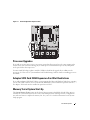 7
7
-
 8
8
-
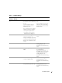 9
9
-
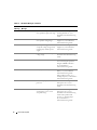 10
10
-
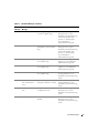 11
11
-
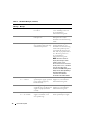 12
12
-
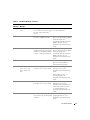 13
13
-
 14
14
-
 15
15
-
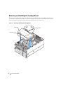 16
16
-
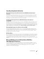 17
17
-
 18
18
-
 19
19
-
 20
20
-
 21
21
-
 22
22
-
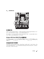 23
23
-
 24
24
-
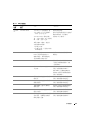 25
25
-
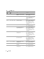 26
26
-
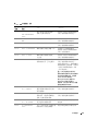 27
27
-
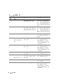 28
28
-
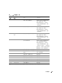 29
29
-
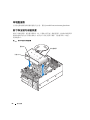 30
30
-
 31
31
-
 32
32
-
 33
33
-
 34
34
-
 35
35
-
 36
36
-
 37
37
-
 38
38
-
 39
39
-
 40
40
-
 41
41
-
 42
42
-
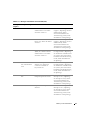 43
43
-
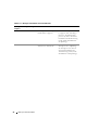 44
44
-
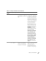 45
45
-
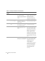 46
46
-
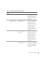 47
47
-
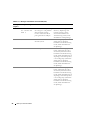 48
48
-
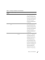 49
49
-
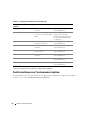 50
50
-
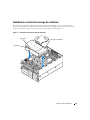 51
51
-
 52
52
-
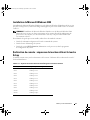 53
53
-
 54
54
-
 55
55
-
 56
56
-
 57
57
-
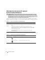 58
58
-
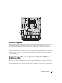 59
59
-
 60
60
-
 61
61
-
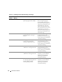 62
62
-
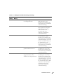 63
63
-
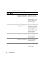 64
64
-
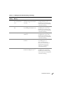 65
65
-
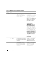 66
66
-
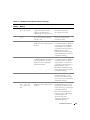 67
67
-
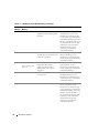 68
68
-
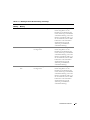 69
69
-
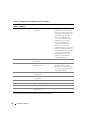 70
70
-
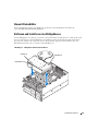 71
71
-
 72
72
-
 73
73
-
 74
74
-
 75
75
-
 76
76
-
 77
77
-
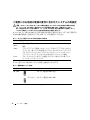 78
78
-
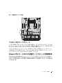 79
79
-
 80
80
-
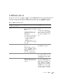 81
81
-
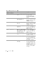 82
82
-
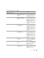 83
83
-
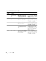 84
84
-
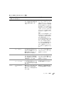 85
85
-
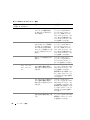 86
86
-
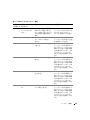 87
87
-
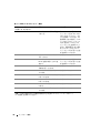 88
88
-
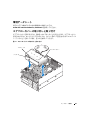 89
89
-
 90
90
-
 91
91
-
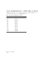 92
92
-
 93
93
-
 94
94
-
 95
95
-
 96
96
-
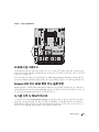 97
97
-
 98
98
-
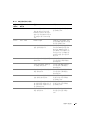 99
99
-
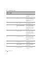 100
100
-
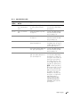 101
101
-
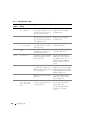 102
102
-
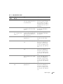 103
103
-
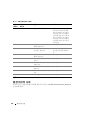 104
104
-
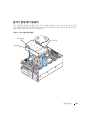 105
105
-
 106
106
-
 107
107
-
 108
108
-
 109
109
-
 110
110
-
 111
111
-
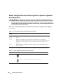 112
112
-
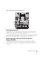 113
113
-
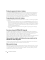 114
114
-
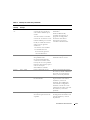 115
115
-
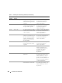 116
116
-
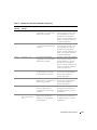 117
117
-
 118
118
-
 119
119
-
 120
120
-
 121
121
-
 122
122
-
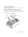 123
123
-
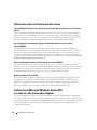 124
124
-
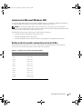 125
125
-
 126
126


Dell 6800 Manual de usuario
- Tipo
- Manual de usuario
- Este manual también es adecuado para
en otros idiomas
- français: Dell 6800 Manuel utilisateur
- Deutsch: Dell 6800 Benutzerhandbuch
- 日本語: Dell 6800 ユーザーマニュアル
Artículos relacionados
-
Dell PowerEdge 6850 serie Guía del usuario
-
-
-
-
-
-
-
Dell PowerEdge 2800 Guía del usuario
-
-