Alpine HCE-C105 El manual del propietario
- Categoría
- Sistemas de video del coche
- Tipo
- El manual del propietario

R
ALPINE ELECTRONICS MARKETING, INC.
1-1-8 Nishi Gotanda,
Shinagawa-ku,
Tokyo 141-0031, Japan
Phone 03-5496-8231
ALPINE ELECTRONICS OF AMERICA, INC.
19145 Gramercy Place, Torrance,
California 90501, U.S.A.
Phone 1-800-ALPINE-1 (1-800-257-4631)
ALPINE ELECTRONICS OF CANADA, INC.
777 Supertest Road, Toronto,
Ontario M3J 2M9, Canada
Phone 1-800-ALPINE-1 (1-800-257-4631)
ALPINE ITALIA S.p.A.
Viale C. Colombo 8, 20090 Trezzano
Sul Naviglio (MI), Italy
Phone 02-484781
ALPINE ELECTRONICS DE ESPAÑA, S.A.
Portal de Gamarra 36, Pabellón, 32
01013 Vitoria (Alava)-APDO 133, Spain
Phone 945-283588
ALPINE ELECTRONICS (BENELUX) GmbH
Leuvensesteenweg 510-B6,
1930 Zaventem, Belgium
Phone 02-725-13 15
ALPINE ELECTRONICS OF AUSTRALIA PTY. LTD.
161-165 Princes Highway, Hallam
Victoria 3803, Australia
Phone 03-8787-1200
ALPINE ELECTRONICS GmbH
Frankfurter Ring 117, 80807 München, Germany
Phone 089-32 42 640
ALPINE ELECTRONICS OF U.K. LTD.
Alpine House
Fletchamstead Highway, Coventry CV4 9TW, U.K.
Phone 0870-33 33 763
ALPINE ELECTRONICS FRANCE S.A.R.L.
(RCS PONTOISE B 338 101 280)
98, Rue de la Belle Etoile, Z.I. Paris Nord Il,
B.P. 50016, 95945 Roissy Charles de Gaulle
Cedex, France
Phone 01-48638989
HCE-C105
• OWNER’S MANUAL
Please read before using this equipment.
• MODE D’EMPLOI
Veuillez lire avant d’utiliser cet appareil.
• MANUAL DE OPERACIÓN
Léalo antes de utilizar este equipo.
• BEDIENUNGSANLEITUNG
Lesen Sie diese Bedienungsanleitung bitte vor Gebrauch
des Gerätes.
• ISTRUZIONI PER L’USO
Si prega di leggere prima di utilizzare il attrezzatura.
• ANVÄNDARHANDLEDNING
Innan du använder utrustningen bör du läsa igenom denna
användarhandledning.
•
Rearview Camera
Designed by ALPINE Japan
Printed in Korea (Y)
68-12118Z92-A
Kukje Printing Co., Ltd
127-2 Gamjeon-dong
Sasang-gu
Busan Korea
Operating Instructions
English
WARNING
This symbol means important instructions. Failure to heed
them can result in serious injury or death.
WHEN REVERSING THE CAR, CHECKING BEHIND AND AROUND THE CAR
MUST BE DONE VISUALLY BY THE DRIVER.
The rearview camera assists the driver in checking behind by sending images to the screen
showing conditions behind the car. The camera uses a wide-angle lens, therefore, there is a
difference in distance perspective between what is normally seen and what appears on the
screen. Also, the images shown by the camera are reversed, so as to appear the same as what is
seen through the rearview mirror.
DO NOT DISASSEMBLE OR ALTER.
Doing so may result in an accident, fire or electric shock.
KEEP SMALL OBJECTS SUCH AS SCREWS OUT OF THE REACH OF CHILDREN.
Swallowing them may result in serious injury. If swallowed, consult a physician immediately.
USE THE CORRECT AMPERE RATING WHEN REPLACING FUSES.
Failure to do so may result in fire or electric shock.
USE ONLY IN CARS WITH A 12 VOLT NEGATIVE GROUND.
(Check with your dealer if you are not sure.) Failure to do so may result in fire, etc.
BEFORE WIRING, DISCONNECT THE CABLE FROM THE NEGATIVE BATTERY
TERMINAL.
Failure to do so may result in electric shock or injury due to electrical shorts.
DO NOT USE BOLTS OR NUTS IN THE BRAKE OR STEERING SYSTEMS TO
MAKE GROUND CONNECTIONS.
Bolts or nuts used for the brake or steering systems (or any other safety-related system), or
tanks should NEVER be used for installations or ground connections. Using such parts could
disable control of the vehicle and cause fire etc.
DO NOT DAMAGE PIPE OR WIRING WHEN DRILLING HOLES.
When drilling holes in the chassis for installation, take precautions so as not to contact, damage
or obstruct pipes, fuel lines, tanks or electrical wiring. Failure to take such precautions may
result in fire.
MAKE THE CORRECT CONNECTIONS.
Failure to make the proper connections may result in fire or product damage.
USE THIS PRODUCT FOR MOBILE 12V APPLICATIONS.
Use for other than its designed application may result in fire, electric shock or other injury.
CHECK THAT THE CAMERA MOUNTING IS ATTACHED SECURELY, AND THAT
THE SCREWS ARE TIGHT BEFORE DRIVING.
Failure to do so may result in an accident.
WHEN INSTALLING THE CAMERA, OR WHEN CHECKING IT IS INSTALLED
SECURELY, DO SO AFTER PARKING THE CAR IN A LEVEL, SAFE PLACE,
TURNING OFF THE ENGINE, AND APPLYING THE HAND BRAKE.
Failure to do so may result in an accident.
WHEN USING A DRILL TO MAKE A HOLE, TAKE PRECAUTIONS SUCH AS
WEARING GOGGLES SO FRAGMENTS DO NOT GET INTO THE EYES.
Failure to do so may result in injury.
CAUTION
This symbol means important instructions. Failure to heed
them can result in injury or material property damage.
HAVE THE WIRING AND INSTALLATION DONE BY EXPERTS.
The wiring and installation of this unit requires special technical skill and experience. To ensure
safety, always contact the dealer where you purchased this product to have the work done.
ARRANGE THE WIRING SO IT IS NOT CRIMPED OR PINCHED BY A SHARP
METAL EDGE.
Route the cables and wiring away from moving parts (like the seat rails) or sharp or pointed
edges. This will prevent crimping and damage to the wiring. If wiring passes through a hole in
metal, use a rubber grommet to prevent the wire’s insulation from being cut by the metal edge
of the hole.
USE SPECIFIED ACCESSORY PARTS AND INSTALL THEM SECURELY.
Be sure to use only the specified accessory parts. Use of other than designated parts may
damage this unit internally or may not securely install the unit in place. This may cause parts to
become loose resulting in hazards or product failure.
HALT USE IMMEDIATELY IF A PROBLEM APPEARS.
Failure to do so may cause personal injury or damage to the product. Return it to your
authorized Alpine dealer or the nearest Alpine Service Centre for repairing.
EXCEPT FOR THE REARVIEW CAMERA ITSELF, DO NOT ATTACH ANY PARTS TO
AREAS WHICH WILL GET WET, OR WHERE THERE IS A LOT OF HUMIDITY OR
DUST.
Failure to do so may result in fire or damage.
DO NOT ATTACH THE CAMERA MOUNTING TO FLUOROCARBON RESIN
FINISHED CAR BODIES OR GLASS.
Doing so could cause the strength of the camera mounting to weaken, which could cause it to
fall of and cause accidents, injury, or damage to the car body.
DO NOT ATTACH THE CAMERA MOUNTING TO ANY SURFACE WHERE THE
ENTIRE ADHESIVE SURFACE CANNOT BE APPLIED.
Doing so could cause the strength of the camera mounting to weaken, which could cause it to
fall of and cause accidents, injury, or damage to the car body.
PRECAUTIONS
• Do not assert any excess pressure to the camera or the mounting, as this could cause the
camera direction to shift, or the camera mounting to come off.
•To prevent the camera lens, mounting and cords from changing colour or shape, or from
deteriorating, wipe with a chemical-free, damp cloth.
• When washing the car, do not using an automatic car washer, or high-pressure washer.
Doing so could cause the camera to come off, damage to the camera cord, or may allow
water to enter the camera or the inside of the car.
• Be sure to disconnect the cable from the (–) battery post before installing your HCE-C105.
This will reduce any chance of damage to the unit in case of a short-circuit.
• Be sure to connect the colour coded leads according to the diagram. Incorrect connections
may cause the unit to malfunction or damage to the vehicle's electrical system.
• When making connections to the vehicle's electrical system, be aware of the factory
installed components (e.g. on-board computer). Do not tap into these leads to provide
power for this unit. When connecting the HCE-C105 to the fuse box, make sure the fuse for
the intended circuit of the HCE-C105 has the appropriate amperage. Failure to do so may
result in damage to the unit and/or the vehicle. When in doubt, consult your Alpine dealer.
• In some cases, to attach the camera, a hole must be drilled in the car body, requiring use of
touch-up paint (retail product) for rust-prevention, and should be prepared beforehand.
Mode d'emploi
Français
AVERTISSEMENT
Ce symbole désigne des instructions importantes. Le non-
respect de ces instructions peut entraîner de graves
blessures, voire la mort.
LORSQUE LE CONDUCTEUR FAIT MARCHE ARRI
È
RE, IL DOIT FAIRE
ATTENTION
À
CE QUI SE PASSE DERRI
È
RE ET SUR LES C
Ô
T
É
S.
La caméra arrière aide le conducteur à contrôler ce qui se passe derrière le véhicule en
transmettant sur l’écran une vue de l’arrière. La caméra utilise un objectif grand-angulaire et
par conséquent, la distance perçue par le conducteur est différente de la perspective qui
s’affiche à l’écran. De plus, les images captées par la caméra sont inversées afin qu’elles
reproduisent exactement la vue du rétroviseur.
NE PAS DESASSEMBLER NI MODIFIER L’APPAREIL.
Il y a risque d’accident, d’incendie ou de choc électrique.
GARDER LES PETITS OBJETS COMME LES VIS HORS DE PORTEE DES
ENFANTS.
L’ingestion de tels objets peut entraîner de graves blessures. En cas d’ingestion, consulter
immédiatement un médecin.
UTILISER DES FUSIBLES DE L’AMPERAGE APPROPRIE.
Il y a risque d’incendie ou de décharge électrique.
A UTILISER UNIQUEMENT SUR DES VOITURES A MASSE NEGATIVE DE 12
VOLTS.
(Vérifiez auprès de votre concessionnaire si vous n’en êtes pas certain.) Il y a risque d’incendie,
etc.
AVANT TOUTE CONNEXION, DEBRANCHER LE CABLE DE LA BORNE NEGATIVE
DE LA BATTERIE.
Il y a risque de choc électrique ou de blessure par courts-circuits.
NE PAS UTILISER DES ECROUS NI DES BOULONS DU CIRCUIT DE FREINAGE
OU DE DIRECTION POUR LES CONNEXIONS DE MASSE.
Les boulons et les écrous utilisés pour les circuits de freinage et de direction (ou de tout autre
système de sécurité) ou les réservoirs ne peuvent JAMAIS être utilisés pour l’installation ou la
liaison à la masse. L’utilisation de ces organes peut désactiver le système de contrôle du
véhicule et causer un incendie, etc.
NE PAS ENDOMMAGER DE CONDUITES NI DE CABLES LORS DU FORAGE DES
TROUS.
Lors du forage de trous dans le châssis en vue de l’installation, veiller à ne pas entrer en
contact, endommager ni obstruer de conduites, de tuyaux à carburant ou de fils électriques. Le
non-respect de cette précaution peut entraîner un incendie.
EFFECTUER CORRECTEMENT LES CONNEXIONS.
Il y a risque de blessures ou de dommages à l’appareil.
UTILISER CET APPAREIL POUR DES APPLICATIONS MOBILES DE 12 V.
Toute utilisation autre que l’application désignée comporte un risque d’incendie, de choc
électrique ou de blessure.
AVANT LA CONDUITE, V
É
RIFIEZ QUE LE SUPPORT DE LA CAM
É
RA EST
CORRECTEMENT FIX
É
ET QUE LES VIS SONT BIEN SERR
É
ES.
Faute de quoi, vous pourriez avoir un accident.
POUR INSTALLER LA CAMÉRA OU POUR VÉRIFIER QU’ELLE EST
CORRECTEMENT INSTALLÉE, GAREZ VOTRE VÉHICULE DANS UN LIEU SÛR ET
SUR UNE SURFACE PLANE, COUPEZ LE MOTEUR ET METTEZ LE FREIN À MAIN.
Faute de quoi, vous pourriez avoir un accident.
SI VOUS UTILISEZ UNE PERCEUSE POUR FAIRE UN TROU, VEILLEZ
À
BIEN
VOUS PROT
É
GER AVEC DES LUNETTES SP
É
CIALES AFIN QU’AUCUN D
É
BRIS
NE P
É
N
È
TRE DANS VOS YEUX.
Faute de quoi, vous pourriez vous blesser.
ATTENTION
Ce symbole désigne des instructions importantes. Le non-
respect de ces instructions peut entraîner des blessures ou
des dommages matériels.
FAIRE INSTALLER LE CABLAGE ET L’APPAREIL PAR DES EXPERTS.
Le câblage et l’installation de cet appareil requiert des compétences techniques et de
l’expérience. Pour garantir la sécurité, faire procéder à l’installation de cet appareil par le
distributeur qui vous l’a vendu.
FAIRE CHEMINER LE CABLAGE DE MANIERE A NE PAS LE COINCER CONTRE
UNE ARETE METALLIQUE.
Faire cheminer les câbles à l’écart des pièces mobiles (comme les rails d’un siège) et des arêtes
acérées ou pointues. Cela évitera ainsi de coincer et d’endommager les câbles. Si un câble passe
dans un orifice métallique, utiliser un passe-cloison en caoutchouc pour éviter que la gaine
isolante du câble ne soit endommagée par le rebord métallique de l’orifice.
UTILISER LES ACCESSOIRES SPECIFIES ET LES INSTALLER CORRECTEMENT.
Utiliser uniquement les accessoires spécifiés. L’utilisation d’autres composants que les
composants spécifiés peut causer des dommages internes à cet appareil ou son installation
risque de ne pas être effectuée correctement. Les pièces utilisées risquent de se desserrer et de
provoquer des dommages ou une défaillance de l’appareil.
INTERROMPRE TOUTE UTILISATION EN CAS DE PROBLEME.
Le non-respect de cette précaution peut entraîner des blessures ou endommager l’appareil.
Retourner l’appareil auprès du distributeur Alpine agréé ou un centre de service après-vente
Alpine en vue de la réparation.
OUTRE LA CAMÉRA ARRI
È
RE, NE FIXEZ AUCUN OBJET DANS UN ENDROIT
EXPOSÉ
À
L’HUMIDITÉ OU
À
LA POUSSI
È
RE.
Faute de quoi, vous pourriez endommager votre véhicule ou provoquer un incendie.
NE FIXEZ PAS LE SUPPORT DE LA CAMÉRA SUR DES REVÊTEMENTS EN
RÉSINE FLUOROCARBONÉE OU EN VERRE.
Cela risquerait de diminuer la résistance du support de la caméra, celui-ci pourrait tomber et
provoquer un accident et des blessures ou endommager le revêtement du véhicule.
ÉVITEZ TOUT EMPLACEMENT DONT LA SURFACE N’EST PAS ASSEZ LARGE
POUR FIXER LE SUPPORT DE LA CAMÉRA.
Cela risquerait de diminuer la résistance du support de la caméra, celui-ci pourrait tomber et
provoquer un accident et des blessures ou endommager le revêtement du véhicule.
PRÉCAUTIONS
• N’exercez aucune pression excessive sur la caméra ou sur le support ; la caméra pourrait se
déplacer et le support pourrait se détacher.
• Pour éviter que l’objectif change de couleur, que le support se déforme ou que les câbles se
détériorent, nettoyez-les avec un chiffon humide en fibres naturelles.
•Lorsque vous nettoyez votre véhicule, n’utilisez pas les stations de lavage automatique ou
les laveurs à haute pression. La caméra pourrait se détacher, endommager le câble et de
l’eau risquerait de pénétrer à l’intérieur du véhicule et de la caméra.
• S’assurer de déconnecter le câble du pôle (–) de la batterie avant l’installation du HCE-
C105. Ceci reduit les risques d’endommager l’unité en cas de court-circuit.
•S’assurer de connecter les conducteurs codés en couleur se conformant au schéma. Des
connexions incorrectes peuvent occasionner le manuvais fonctionnement de l’unité ou le
dégât du système électrique du véhicule.
• Lors de la connexion des câbles au système électrique du véhicule, il faut être conscient des
composants installés en usine (tel qu’un ordinateur de bord). S’assurer de ne pas brancher à
ces conducteurs pour fournir l’alimentation à cette unité. Lors de la connexion du HCE-
C105 au boîtier à fusible, s’assurer que le fusible du circuit désigné pour le HCE-C105 a
l’ampérage approprié. Sinon, I’unité et/ou le véhicule peuvent être endommagés. En cas de
doute, consulter le revendeur Alpine.
•Dans certains cas, il est nécessaire de percer un trou dans la carrosserie pour installer la
caméra ; dans ce cas, prévoyez une retouche avec une peinture spéciale (vendue dans le
commerce) afin de protéger le véhicule contre la rouille.
Manual de instrucciones
Español
ADVERTENCIA
Este símbolo indica que las instrucciones son importantes.
De no tenerse en cuenta, podría ocasionarse heridas graves
o muerte.
DURANTE LA MARCHA ATR
Á
S DEL VEHÍCULO, EL CONDUCTOR DEBE
CONTROLAR VISUALMENTE LAS VISTAS LATERAL Y POSTERIOR DEL COCHE.
La cámara trasera ayuda al conductor a comprobar el estado de la vista posterior enviando
imágenes a la pantalla. La cámara utiliza lentes de gran ángulo, por lo que existen diferencias
de perspectiva de distancia entre lo que se ve por la pantalla y lo que hay en realidad.
Asimismo, las imágenes que muestra la cámara están invertidas y se visualizan del mismo
modo que si se viesen a través del espejo retrovisor.
NO DESMONTE NI ALTERE LA UNIDAD.
Si lo hace, podrá ocasionar un accidente, un incendio o una descarga eléctrica.
MANTENGA LOS OBJETOS PEQUEÑOS, COMO LOS TORNILLOS, FUERA DEL
ALCANCE DE LOS NIÑOS.
La ingestión de estos objetos puede provocar lesiones graves. Si esto ocurre, consulte con un
médico inmediatamente.
UTILICE EL AMPERAJE CORRECTO CUANDO CAMBIE FUSIBLES.
De lo contrario, puede producirse un incendio o una descarga eléctrica.
UTILICE LA UNIDAD SOLAMENTE EN VEHÍCULOS QUE TENGAN 12 VOLTIOS
CON NEGATIVO A MASA.
(Consulte a su distribuidor en caso de duda.) De no ser así, podría ocasionar un incendio, etc.
ANTES DE EFECTUAR EL CABLEADO, DESCONECTE EL CABLE DEL TERMINAL
NEGATIVO DE LA BATERÍA.
De no hacerlo así, podría ocasionar una descarga eléctrica o heridas debido a cortocircuitos
eléctricos.
NO UTILICE TUERCAS O PERNOS EN EL SISTEMA DE FRENOS O DE DIRECCIÓN
PARA REALIZAR LAS CONEXIONES A MASA.
Los pernos o tuercas empleados en los sistemas de freno o de dirección (o en cualquier otro
sistema relacionado con la seguridad del vehículo), o los depósitos, NUNCA deben utilizarse
para instalaciones de cableado o conexión a masa. Si utiliza tales partes podrá incapacitar el
control del vehículo y provocar un incendio, etc.
EVITE DAÑAR LOS TUBOS Y EL CABLEADO CUANDO TALADRE AGUJEROS.
Si taladra agujeros en el chasis durante la instalación, tome las precauciones necesarias para no
rozar, dañar u obstruir los tubos, las tuberías de combustible, los depósitos o el cableado
eléctrico. De lo contrario, podría provocar un incendio.
REALICE LAS CONEXIONES CORRECTAMENTE.
Una conexión incorrecta puede producir un incendio o dañar el equipo.
UTILICE ESTE PRODUCTO CON APLICACIONES MÓVILES DE 12 V.
Si se emplea para otra aplicación distinta de la prevista, podría producirse un incendio, una
descarga eléctrica u otras lesiones.
ANTES DE INICIAR LA MARCHA, VERIFIQUE QUE EL SOPORTE DE LA CÁMARA SE
HA FIJADO CORRECTAMENTE Y QUE LOS TORNILLOS ESTÁN BIEN APRETADOS.
De lo contrario, podría tener un accidente.
AL INSTALAR LA C
Á
MARA, O DURANTE LA COMPROBACIÓN DE SU
INSTALACIÓN, LLEVE A CABO LA VERIFICACIÓN CON EL VEHÍCULO APARCADO
EN UN LUGAR SEGURO Y NIVELADO, CON EL MOTOR APAGADO Y CON EL
FRENO DE MANO PUESTO.
De lo contrario, podría tener un accidente.
SI UTILIZA UN TALADRO PARA HACER LOS AGUJEROS, PROTÉJASE
ADECUADAMENTE CON GAFAS PROTECTORAS PARA EVITAR QUE LOS
POSIBLES FRAGMENTOS LE ALCANCEN LOS OJOS.
De lo contrario, podría hacerse daño.
PRUDENCIA
Este símbolo indica que las instrucciones son importantes.
De no tenerse en cuenta, podría ocasionarse heridas graves
o daños materiales.
CONFÍE EL CABLEADO Y LA INSTALACIÓN A PROFESIONALES.
El cableado y la instalación de este equipo requieren una competencia y experiencia técnica
confirmada. Para garantizar la seguridad, póngase siempre en contacto con el distribuidor al que
ha comprado el equipo para confiarle estas tareas.
DISPONGA EL CABLEADO DE FORMA QUE LOS CABLES NO SE DOBLEN, NO SE
CONTRAIGAN NI ROCEN UN BORDE METÁLICO AFILADO.
Aleje los cables y el cableado de piezas móviles (como los raíles de los asientos) o de bordes
puntiagudos o afilados. De esta forma evitará dobleces y daños en el cableado. Si los cables se
introducen por un orificio de metal, utilice una arandela de goma para evitar que el borde
metálico del orificio corte el aislamiento del cable.
UTILICE LOS ACCESORIOS ESPECIFICADOS E INSTÁLELOS CORRECTAMENTE.
Asegúrese de utilizar los accesorios especificados solamente. La utilización de otras piezas no
designadas puede ser la causa de daños en el interior de la unidad o de una instalación
incorrecta. Las piezas pueden aflojarse, lo que, además de ser peligroso, puede provocar
averías.
DEJE DE USAR LA UNIDAD INMEDIATAMENTE SI APARECE ALGÚN PROBLEMA.
Su uso en estas condiciones podría ocasionar lesiones personales o daños al producto. Lleve la
unidad a un distribuidor Alpine autorizado o al Centro de servicio Alpine más próximo para
repararla.
SALVO LA PROPIA C
Á
MARA TRASERA, NO COLOQUE NINGUNA OTRA PIEZA
EN
Á
REAS EN LAS QUE PUDIERAN MOJARSE O DONDE SE ACUMULE MUCHA
HUMEDAD Y POLVO.
De lo contrario, podría provocar un incendio o una avería.
NO COLOQUE EL SOPORTE DE LA C
Á
MARA SOBRE ELEMENTOS DEL
VEHÍCULO CON ACABADO DE RESINA DE FLUOROCARBONO NI SOBRE
ELEMENTOS DE VIDRIO.
Si lo hace, podría reducir la resistencia del soporte de la cámara y hacer que se caiga,
provocando un accidente, daños o averías en la carrocería.
NO COLOQUE EL SOPORTE DE LA C
Á
MARA EN NINGUNA SUPERFICIE EN LA
QUE NO SE PUEDA FIJAR LA SUPERFICIE ADHESIVA POR COMPLETO.
Si lo hace, podría reducir la resistencia del soporte de la cámara y hacer que se caiga,
provocando un accidente, daños o averías en la carrocería.
PRECAUCIONES
•No aplique ninguna presión adicional a la cámara o a su soporte, ya que podría alterar la
dirección de la cámara o desprender el soporte.
•Para evitar que cambie la forma y el color de la lente, el soporte o los cables de la cámara y para
impedir que se deterioren, realice la limpieza con un paño húmedo y sin productos químicos.
•Cuando lave el coche, no lo haga en túneles de lavado ni con máquinas de limpieza a
presión. Si lo hace, la cámara podría desprenderse, el cable podría dañarse o podría
introducirse agua en la cámara o en el interior del vehículo.
• Asegúrese de desconectar el cable del polo (–) de la batería antes de instalar su HCE-C105.
Esto reducirá las posibilidades de averiar la unidad en caso de cortocircuito.
• Asegúrese de conectar los conductores con clave de colores según el diagrama. Unas
conexiones incorrectas pueden ocasionar un mal funcionamiento de la unidad o pueden
dañar el sistema eléctrico del vehículo.
•Cuando haga las conexiones al sistema eléctrico del vehículo, tenga en cuenta los
componentes que vienen instalados de fábrica (como un computador incorporado, por
ejemplo). No conecte a estos conductores para proporcionar alimentación a esta unidad. Al
conectar el HCE-C105 a la caja de fusibles, asegúrese de que el fusible designado para el
circuito del HCE-C105 sea del amperaje adecuado. De lo contrario, Ia unidad y/o el
vehículo podrán sufrir daños. Cuando tenga dudas, consulte a su distribuidor Alpine.
• En algunos casos, es preciso taladrar un agujero en la carrocería del vehículo para colocar
la cámara, por lo que deberá utilizar pintura para retocar la carrocería y evitar la oxidación.
Esto debe estar preparado antes de llevar a cabo la instalación.
Bedienungsanleitung
WARNUNG
Dieses Symbol weist auf wichtige Anweisungen hin. Bei
Nichtbeachtung besteht die Gefahr von schweren
Verletzungen oder Todesfällen.
WENN DER RÜCKWÄRTSGANG EINGELEGT IST, MUSS DER FAHRER DARAUF
ACHTEN, WAS SICH HINTER ODER NEBEN SEINEM AUTO BEFINDET.
Die Rückfahrkamera hilft dem Fahrer dabei zu sehen, was sich hinter dem Auto befindet, indem
sie Bilder von den Gegebenheiten hinter dem Auto auf den Bildschirm überträgt. Die Kamera
verfügt über ein Weitwinkelobjektiv, daher ist die Perspektive der Distanzen zwischen dem, was
man mit bloßem Auge sieht und dem, was auf dem Bildschirm angezeigt wird, unterschiedlich.
Darüber hinaus ist das von der Kamera angezeigte Bild seitenverkehrt, sodass es der Anzeige
im Rückspiegel entspricht.
GERÄT NICHT ÖFFNEN.
Andernfalls besteht Unfallgefahr, Feuergefahr oder die Gefahr eines elektrischen Schlages.
KLEINE GEGENSTÄNDE WIE SCHRAUBEN VON KINDERN FERNHALTEN.
Werden solche Gegenstände verschluckt, besteht die Gefahr schwerwiegender Verletzungen.
Suchen Sie unverzüglich einen Arzt auf, wenn ein Kind einen solchen Gegenstand verschluckt.
SICHERUNGEN IMMER DURCH SOLCHE MIT DER RICHTIGEN AMPEREZAHL
ERSETZEN.
Andernfalls besteht Feuergefahr oder die Gefahr eines elektrischen Schlages.
NUR IN FAHRZEUGEN MIT 12-VOLT-BORDNETZ UND MINUS AN MASSE
VERWENDEN.
Fragen Sie im Zweifelsfall Ihren Händler. Andernfalls besteht Feuergefahr usw.
VOR DEM ANSCHLUSS DAS KABEL VOM MINUSPOL DER BATTERIE
ABKLEMMEN.
Andernfalls besteht die Gefahr eines elektrischen Schlages oder Verletzungsgefahr durch einen
Kurzschluss.
BOLZEN UND MUTTERN DER BREMSANLAGE NICHT ALS MASSEPUNKTE
VERWENDEN.
Verwenden Sie für Einbau oder Massenanschluss NIEMALS Bolzen oder Muttern der Brems-
bzw. Lenkanlage oder eines anderen sicherheitsrelevanten Systems oder des Benzintanks.
Andernfalls besteht die Gefahr, dass Sie die Kontrolle über das Fahrzeug verlieren oder ein
Feuer ausbricht.
BEIM BOHREN VON LÖCHERN LEITUNGEN UND KABEL NICHT BESCHÄDIGEN.
Wenn Sie beim Einbauen Löcher in das Fahrzeugchassis bohren, achten Sie unbedingt darauf,
die Kraftstoffleitungen und andere Leitungen, den Benzintank und elektrische Kabel nicht zu
berühren, zu beschädigen oder zu blockieren. Andernfalls besteht Feuergefahr.
AUF KORREKTE ANSCHLÜSSE ACHTEN.
Bei fehlerhaften Anschlüssen besteht Feuergefahr, und es kann zu Schäden am Gerät kommen.
DAS GERÄT NUR AN EIN 12-V-BORDNETZ IN EINEM FAHRZEUG
ANSCHLIESSEN.
Andernfalls besteht Feuergefahr, die Gefahr eines elektrischen Schlages oder anderer
Ve rletzungen.
ÜBERPRÜFEN SIE VOR DEM LOSFAHREN, OB DIE KAMERAHALTERUNG FEST
ANGEBRACHT IST UND OB DIE SCHRAUBEN FESTGEZOGEN SIND.
Andernfalls kann es zu einem Unfall kommen.
WENN SIE DIE KAMERA MONTIEREN ODER IHRE MONTAGE ÜBERPRÜFEN
MÖCHTEN, TUN SIE DIES AN EINEM EBENEN, SICHEREN ORT, SCHALTEN SIE
DEN MOTOR AUS, UND ZIEHEN SIE DIE HANDBREMSE AN.
Andernfalls kann es zu einem Unfall kommen.
WENN SIE MITHILFE EINES BOHRERS EIN LOCH BOHREN, SETZEN SIE EINE
SCHUTZBRILLE AUF, DAMIT KEINE SPLITTER IN DIE AUGEN GELANGEN
KÖNNEN.
Andernfalls könnten Sie sich verletzen.
VORSICHT
Dieses Symbol weist auf wichtige Anweisungen hin. Bei
Nichtbeachtung besteht die Gefahr von Verletzungen bzw.
Sachschäden.
VERKABELUNG UND EINBAU VON FACHPERSONAL AUSFÜHREN LASSEN.
Die Verkabelung und der Einbau dieses Geräts erfordern technisches Geschick und Erfahrung.
Zu Ihrer eigenen Sicherheit sollten Sie Verkabelung und Einbau dem Händler überlassen, bei
dem Sie das Gerät erworben haben.
DIE KABEL SO VERLEGEN, DASS SIE NICHT GEKNICKT ODER DURCH SCHARFE
KANTEN GEQUETSCHT WERDEN.
Verlegen Sie die Kabel so, dass sie sich nicht in beweglichen Teilen wie den Sitzschienen
verfangen oder an scharfen Kanten oder spitzen Ecken beschädigt werden können. So
verhindern Sie eine Beschädigung der Kabel. Wenn Sie ein Kabel durch eine Bohrung in einer
Metallplatte führen, schützen Sie die Kabelisolierung mit einer Gummitülle vor Beschädigung
durch die Metallkanten der Bohrung.
NUR DAS VORGESCHRIEBENE ZUBEHÖR VERWENDEN UND DIESES SICHER
EINBAUEN.
Verwenden Sie ausschließlich das vorgeschriebene Zubehör. Andernfalls wird das Gerät
möglicherweise beschädigt, oder es lässt sich nicht sicher einbauen. Wenn sich Teile lösen,
stellen diese eine Gefahrenquelle dar, und es kann zu Betriebsstörungen kommen.
DAS GERÄT NICHT WEITERBENUTZEN, WENN EIN PROBLEM AUFTRITT.
Andernfalls kann es zu Verletzungen oder Schäden am Gerät kommen. Geben Sie das Gerät zu
Reparaturzwecken an einen autorisierten Alpine-Händler oder den nächsten Alpine-Kundendienst.
BRINGEN SIE MIT AUSNAHME DER R
Ü
CKFAHRKAMERA SELBST KEINE TEILE AN
STELLEN AN, DIE NASS WERDEN K
Ö
NNEN ODER AN DENEN VIEL FEUCHTIGKEIT
ODER STAUB ENTSTEHT.
Andernfalls kann ein Feuer oder Schaden verursacht werden.
BRINGEN SIE DIE KAMERAHALTERUNG NICHT AN EINER KAROSSERIE MIT
KUNSTHARZEN AUS FLUORIERTEM KOHLENWASSERSTOFF ODER AN
GLASSFLÄCHEN AN.
Andernfalls könnte die Stärke der Kamerabefestigung abnehmen, sodass die Kamera abfallen
und Unfälle, Verletzungen oder Beschädigungen an der Karosserie verursachen kann.
BRINGEN SIE DIE KAMERAHALTERUNG NICHT AN EINER OBERFLÄCHE AN,
AUF DIE NICHT DIE GESAMTE KLEBEFLÄCHE ANGEWANDT WERDEN KANN.
Andernfalls könnte die Stärke der Kamerabefestigung abnehmen, sodass die Kamera abfallen
und Unfälle, Verletzungen oder Beschädigungen an der Karosserie verursachen kann.
VORSICHTSMASSNAHMEN
• Üben Sie keinen übermäßigen Druck auf die Kamera oder Halterung aus, da dies dazu führen kann, dass
sich die Richtung der Kamera verändert oder dass sich die Kamerahalterung löst.
• Um zu verhindern, dass sich das Kameraobjektiv, die Befestigung und die Kabel in Farbe oder Form
verändern oder verschlechtern, reinigen Sie sie mit einem feuchten, chemikalienfreien Tuch.
•Wenn Sie das Auto waschen, nutzen Sie keine automatische Waschanlage und keinen Hochdruckreiniger.
Andernfalls kann sich die Kamera lösen, das Kamerakabel beschädigt werden oder Wasser ins Innere der
Kamera oder des Autos eindringen.
•Trennen Sie unbedingt das Kabel vom negativen (–) Pol der Batterie, bevor Sie den HCE-C105 installieren.
Dadurch vermeiden Sie die Gefahr einer Beschädigung des Geräts, falls es zu einem Kurzschluss kommt.
• Schließen Sie die farbcodierten Leitungen wie im Diagramm angegeben an. Falsche Verbindungen können
zu Fehlfunktionen am Gerät oder zu Beschädigungen am elektrischen System des Fahrzeugs führen.
•Wenn Sie Anschlüsse an das elektrische System des Fahrzeugs vornehmen, berücksichtigen Sie bitte alle
werkseitig bereits installierten Komponenten (z. B. Bord-Computer). Zapfen Sie nicht die Leitungen
solcher Komponenten an, um dieses Gerät mit Strom zu versorgen. Wenn Sie den HCE-C105 an den
Sicherungskasten anschließen, achten Sie darauf, dass die Sicherung für den Stromkreis, an den Sie das
obengenannte Gerät anschließen wollen, einen geeigneten Ampere-Wert aufweist. Andernfalls kann es zu
Schäden am Gerät und/oder am Fahrzeug kommen. Wenden Sie sich im Zweifelsfall bitte an Ihren
ALPINE-Händler.
• In manchen Fällen muss zum Befestigen der Kamera ein Loch in die Karosserie gebohrt werden, welches
zur Vorbeugung von Roststellen Reparaturlack (im Handel erhältlich) erfordert und im Voraus angemischt
werden sollte.
Istruzioni per l'uso
Italiano
AVVERTIMENTO
Questo simbolo indica istruzioni importanti. La non
osservanza di tali norme potrebbe causare gravi ferite o
morte.
NELLE MANOVRE DI RETROMARCIA, IL CONDUCENTE DEVE ESEGUIRE UNA
VERIFICA VISIVA NELLA PARTE POSTERIORE E INTORNO AL VEICOLO.
La telecamera per la retromarcia consente al conducente di controllare la parte posteriore del
veicolo visualizzando le relative immagini sullo schermo. Poiché la telecamera si avvale di un
obiettivo grandangolare, tenere presente che la distanza effettiva a occhio nudo è diversa da
quella visibile sullo schermo Inoltre, le immagini mostrate dalla telecamera sono capovolte e
vengono presentate così come verrebbero viste attraverso lo specchietto retrovisore.
NON SMONTARE O MODIFICARE.
Tale azione potrebbe causare incidenti, incendi o scosse elettriche.
TENERE LE PARTI PICCOLE QUALI LE VITI FUORI DALLA PORTATA DEI
BAMBINI.
Se ingeriti potrebbero causare gravi danni. In caso di ingerimento, consultare immediatamente
un medico.
USARE FUSIBILI DI RICAMBIO DELL’AMPERAGGIO CORRETTO.
Altrimenti potrebbero derivarne incendi o scosse elettriche.
UTILIZZARE SOLO IN VEICOLI CON TERRA NEGATIVA A 12 VOLT (se non si è
sicuri, controllare con il proprio rivenditore).
Diversamente si potrebbero causare incendi o altri danni.
PRIMA DI ESEGUIRE I COLLEGAMENTI, SCOLLEGARE IL CAVO DEL
TERMINALE NEGATIVO DELLA BATTERIA.
Altrimenti potrebbero derivare scosse elettriche o altre lesioni dovute a cortocircuiti.
PER ESEGUIRE I COLLEGAMENTI DI TERRA, NON UTILIZZARE BULLONI O
DADI DEI SISTEMI DI FRENATA O DI STERZO.
Non utilizzare MAI bulloni o dadi dei sistemi di frenata e di sterzo (o di qualsiasi altro sistema
di sicurezza), o dei serbatoi per eseguire l’installazione o per i collegamenti di terra. L’utilizzo
di queste parti potrebbe inibire il controllo del veicolo e causare incendi o altro.
NELL’EFFETTUARE I FORI, NON DANNEGGIARE I TUBI O I CAVI.
Nell’effettuare i fori nel telaio per l’installazione, fare attenzione a non entrare in contatto,
danneggiare o ostruire i tubi, i condotti della benzina, i serbatoi o i cavi elettrici. La non
osservanza di queste precauzioni potrebbe causare incendi.
ESEGUIRE CORRETTAMENTE I COLLEGAMENTI.
Altrimenti ne potrebbero derivarne incendi o danni al prodotto.
UTILIZZARE IL PRODOTTO IN VEICOLI CON BATTERIA DA 12 V.
Un utilizzo diverso da quello indicato potrebbe causare incendi, scosse elettriche o altri
incidenti.
PRIMA DI AVVIARE IL VEICOLO, ACCERTARSI CHE IL SUPPORTO DELLA
TELECAMERA SIA FISSATO SALDAMENTE E CHE LE VITI SIANO SERRATE IN
MODO ADEGUATO.
Il mancato rispetto di tali precauzioni può essere causa di incidenti.
PER MONTARE LA TELECAMERA O VERIFICARE CHE SIA STATA FISSATA
SALDAMENTE, PARCHEGGIARE IL VEICOLO SU UN PIANO LIVELLATO E
SICURO, SPEGNERE IL MOTORE E INSERIRE IL FRENO DI STAZIONAMENTO.
Il mancato rispetto di tali precauzioni può essere causa di incidenti.
QUANDO SI USA UN TRAPANO PER EFFETTUARE UN FORO, PRENDERE LE
DOVUTE PRECAUZIONI, AD ESEMPIO INDOSSARE OCCHIALI PROTETTIVI PER
GLI OCCHI.
Il mancato rispetto di tali precauzioni può essere causa di lesioni personali.
ATTENZIONE
Questo simbolo indica istruzioni importanti. La non
osservanza di queste norme potrebbe causare ferite o
provocare danni alle cose.
I COLLEGAMENTI E L’INSTALLAZIONE DEVONO ESSERE EFFETTUATI DA
PERSONALE QUALIFICATO.
I collegamenti e l’installazione dell’apparecchio richiedono conoscenze tecniche ed esperienza
particolari. Per ragioni di sicurezza, contattare sempre il rivenditore presso il quale è stato
acquistato il prodotto per eseguire l’installazione.
SISTEMARE I CAVI IN MODO CHE NON VENGANO PIEGATI O COMPRESSI DA
PARTI METALLICHE TAGLIENTI.
Per evitare che vengano danneggiati o piegati, sistemare i cavi e i fili lontano da parti mobili
(quali le guide dei sedili) o da parti taglienti o aguzze. Se i cavi vengono fatti passare attraverso
un foro metallico, utilizzare un anello di gomma per evitare che l’isolante dei cavi venga
tagliato dal bordo metallico del foro.
UTILIZZARE LE PARTI ACCESSORIE SPECIFICATE E INSTALLARLE IN MODO
CORRETTO.
Assicurarsi di utilizzare solo parti accessorie specificate. L’utilizzo di altri componenti potrebbe
danneggiare l’apparecchio all’interno o determinare in un’installazione non corretta. I
componenti potrebbero non rimanere collegati in modo saldo e provocare problemi di
funzionamento o pericoli.
INTERROMPERE IMMEDIATAMENTE L’USO IN CASO DI PROBLEMI.
Diversamente si potrebbero causare danni alla persona o al prodotto. Per riparazioni, rivolgersi
ad un rivenditore autorizzato Alpine o al più vicino centro di assistenza Alpine.
FATTA ECCEZIONE PER LA TELECAMERA DI RETROMARCIA IN SÉ, NON
FISSARE PARTI SU ZONE CHE POSSONO BAGNARSI O ESSERE INTERESSATE
DA UMIDITÀ O POLVERE.
Il mancato rispetto di tale precauzione può essere causa di incendi o danni.
NON FISSARE IL SUPPORTO DELLA TELECAMERA SU FINESTRINI DI VETRO O
PARTI DI CARROZZERIA TRATTATE CON RESINA FLUOROCARBONICA.
In caso contrario, il supporto della telecamera non avrebbe sufficiente presa e potrebbe
staccarsi provocando incidenti, lesioni personali o danni alla carrozzeria.
NON FISSARE IL SUPPORTO DELLA TELECAMERA SU SUPERFICI CHE NON
CONSENTONO DI INCOLLARE L’INTERA BASE ADESIVA.
In caso contrario, il supporto della telecamera non avrebbe sufficiente presa e potrebbe
staccarsi provocando incidenti, lesioni personali o danni alla carrozzeria.
PRECAUZIONI
• Non esercitare una pressione eccessiva sulla telecamera o il suo supporto, poiché ciò potrebbe
deviarne l’orientamento o farla staccare dalla superficie.
• Per evitare che l’obiettivo, il supporto e i cavi della telecamera cambino di colore o forma o
vengano danneggiati, pulire questi elementi usando un panno umido privo di prodotti chimici.
• Per lavare il veicolo non ricorrere a lavaggi automatici o idropulitrici ad alta pressione. Infatti,
l’eccessiva forza applicata da questi metodi può far staccare la telecamera, danneggiarne i cavi o
consentire all’acqua di penetrare nella telecamera o nell’abitacolo.
• Assicurarsi di scollegare il cavo dal polo negativo (–) della batteria prima di installare il lettore
HCE-C105. Così facendo, il rischio di danni all’apparecchio in caso di cortocircuiti viene ridotto.
• Assicurarsi di collegare i cavi differenziati in base al colore in base al diagramma. Collegamenti
errati potrebbero causare problemi di funzionamento o danneggiare il sistema elettrico
dell’automobile.
• Nell’effettuare i collegamenti al sistema elettrico dell’automobile, tenere conto dei componenti
installati in fabbrica (ad esempio, computer di bordo). Non utilizzare questi cavi per fornire
alimentazione all’apparecchio. Quando il lettore HCE-C105 viene collegato alla scatola dei
fusibili, assicurarsi che il fusibile preposto al collegamento con il circuito del lettore HCE-C105
sia dell’amperaggio corretto. Diversamente, l’apparecchio e/o l’automobile potrebbero venire
danneggiati. Se non si è certi dell’amperaggio, contattare un rivenditore ALPINE.
• In molti casi, per fissare la telecamera è necessario praticare un foro nella carrozzeria, nel qual
caso è necessaria una vernice di ritocco antiruggine (prodotto in commercio) da tenere a portata
di mano.
Om dessa instruktioner
Svenska
VARNING!
Den här symbolen markerar viktig information. Ignorera inte
det som sägs här, eftersom det kan leda till allvarliga
olyckor, till och med med dödlig utgång.
NÄR BILEN SKA BACKAS MÅSTE FÖRAREN VISUELLT KONTROLLERA BAKOM
OCH RUNT BILEN.
Backkameran hjälper föraren att titta bakåt genom att skicka bilder till skärmen, där den visar
förhållandena bakom bilen. Kameran använder en vidvinkellins, så därför skiljer sig det
verkliga avståndet från det avstånd man upplever på skärmbilden. Bilderna som kameran visar
har också spegelvänts, så att de visas på samma sätt som det man ser i backspegeln.
TAG INTE ISÄR OCH GÖR INGA ÄNDRINGAR.
Det kan resultera i en olycka, brand eller elektriska stötar.
FÖRVARA MINDRE FÖREMÅL, SOM T.EX. SKRUVEN, UTOM RÄCKHÅLL FÖR
BARN.
Om något föremål skulle sväljas, skall en läkare kontaktas omedelbart.
ANVÄND RÄTT AMPERETAL VID BYTE AV SÄKRINGAR.
Fel amperetal kan orsaka brand eller elektriska stötar.
ANVÄND BARA ENHETEN I BILAR MED 12-VOLTSYSTEM SOM HAR NEGATIV
(–) JORD.
(Återförsäljaren kan hjälpa dig om du är osäker.) Felaktig anslutning kan resultera i brand,
elektriska stötar eller andra skador.
KOPPLA UR KABELN FRÅN DET NEGATIVA (–) UTTAGET PÅ BILBATTERIET
INNAN ANSLUTNINGARNA GÖRS.
Detta för att undvika risken för elektriska stötar eller olycksfall på grund av kortslutning.
MONTERA VARKEN MUTTRAR ELLER BULTAR I NÅGON DEL AV
BROMSSYSTEMET VID JORDANSLUTNINGAR.
Bultar eller muttrar som hör till någon vätsketank, styr- eller bromssystemet (eller något annan
system som är av betydelse för säkerheten) ska ALDRIG användas för kabeldragning eller
jordanslutning. Användandet av sådana delar kan leda till att fordonets styrförmåga försämras
och orsaka bromsfel, brand eller personskada.
SE TILL ATT VARKEN RÖR, VÄTSKELEDNINGAR ELLER KABLAR VIDRÖRS,
SKADAS ELLER FÖRHINDRAS VID BORRNING AV HÅL.
Undersök chassit innan hålen borras så att inte några slangar, kablar, bränsleledningar eller
liknande råkar skadas. Det kan leda till att brand uppstår.
GÖR ANSLUTNINGARNA PÅ KORREKT SÄTT.
Felaktiga anslutningar kan orsaka brand eller skador på enheten.
DEN HÄR PRODUKTEN ÁR ENDAST AVSEDD FÖR MONTERING I BILAR MED 12
VOLTS-SYSTEM.
Annan användning kan resultera i brand, elektriska stötar eller andra skador.
KONTROLLERA ATT KAMERANS FÄSTE SITTER ORDENTLIGT OCH ATT
SKRUVARNA ÄR ÅTDRAGNA INNAN KÖRNING AV BILEN PÅBÖRJAS.
En olycka kan inträffa om detta inte kontrolleras.
NÄR KAMERAN SKA INSTALLERAS, ELLER NÄR MAN KONTROLLERAR ATT
DEN INSTALLERATS KORREKT, MÅSTE BILEN FÖRST PARKERAS PÅ EN PLAN,
SÄKER PLATS, MOTORN STÄNGAS AV OCH HANDBROMSEN DRAS ÅT.
En olycka kan inträffa om detta inte kontrolleras.
ANVÄND SKYDDSGLASÖGON OM DU BORRAR HÅL, SÅ ATT INTE FRAGMENT
HAMNAR I DINA ÖGON.
Personskador kan inträffa om detta inte kontrolleras.
FÖRSIKTIGT!
Den här symbolen markerar viktig information. Ignorera inte
det som sägs här eftersom det kan leda till skador på
person eller egendom.
LÅT EN FACKKUNNIG TEKNIKER GÖRA KABELDRAGNINGEN OCH
MONTERINGEN.
Kabeldragningen och monteringen av denna apparat kräver teknisk kunskap och erfarenhet.
Kontakta återförsäljaren, som sålde apparaten, för utförandet av säker montering.
DRA KABLARNA RAKA OCH SÅ ATT DE INTE KOMMER I KLÄM ELLER SKAVER
MOT SKARPA KANTER.
Undvik kläm- och nötskador genom att se till att kablarna går fria från rörliga delar (t.ex.
bilsätenas glidbanor) och skarpa och spetsiga kanter. Om kablarna måste dras genom hål i
plåten bör gummibussningar användas som skydd, så att inte kablarna ligger och nöter mot
metallen.
ANVÄND ALLTID SPECIFICERADE TILLBEHÖR OCH MONTERA TILLBEHÖREN
ORDENTLIGT.
Användandet av andra delar än som är avsedda för denna apparat kan leda till att apparaten
skadas invändigt eller till ostadig montering på grund av lossnande delar.
AVBRYT GENAST ANVÄNDNING OM PROBLEM UPPSTÅR.
I annat fall kan personskador eller skador på själva enheten uppstå. Lämna apparaten till
återförsäljaren för reparation.
FÖRUTOM SJÄLVA KAMERAN FÅR INGA ANDRA DELAR MONTERAS PÅ
PLATSER SOM KAN BLI VÅTA, ELLER DÄR DET FINNS MYCKET FUKT ELLER
DAMM.
Om detta inte beaktas kan det orsaka brand eller skador.
MONTERA INTE KAMERAFÄSTET PÅ PLÅT ELLER GLAS SOM BEHANDLATS
MED FLUORETENPLAST.
Detta kan försvaga kamerafästet som eventuellt kan ramla av och orsaka olyckor, personskador
eller skador på bilens kaross.
MONTERA INTE KAMERAFÄSTET PÅ EN YTA DÄR INTE HELA DEN
SJÄLVHÄFTANDE YTAN KAN APPLICERAS.
Detta kan försvaga kamerafästet som eventuellt kan ramla av och orsaka olyckor, personskador
eller skador på bilens kaross.
ATT OBSERVERA
• Utsätt inte kameran eller fästet för ytterligare belastning, eftersom det kan få kamerans
riktning att ändras eller fästet att lossna.
•För att kameralinsen, fästet och sladdarna inte ska missfärgas, deformeras eller försämras,
kan du torka av dem med en fuktig trasa, fri från kemikalier.
•Använd inte automatiska biltvättar eller högtrycksprutor när bilen ska rengöras. Det kan få
kameran att lossa, skada kamerans sladd eller få vatten att tränga in i kameran eller bilen.
•Koppla bort kabeln från batteriets minuspol (–) innan du installerar HCE-C105. Då
undviker du risken för kortslutningar som kan skada enheten.
• Se till att du ansluter de färgmärkta kablarna enligt kopplingsschemat. Felaktiga
anslutningar kan göra så att enheten inte fungerar som den ska, och kan också orsaka
skador på fordonets elsystem.
•När du gör anslutningarna till fordonets elsystem måste du ta hänsyn till de komponenter
som redan är installerade (t.ex. en dator). Använd inte ledningarna till sådana komponenter
som strömförsörjningskablar för den här enheten. När du ansluter HCE-C105 till
säkringsplinten måste du se till att säkringen för den krets du tänker använda har rätt
amperetal för HCE-C105. Om du ansluter till en säkring med fel amperetal riskerar du att
skada enheten och/eller fordonets elsystem. Kontakta din ALPINE-återförsäljare om du
känner dig osäker.
•I vissa fall måste ett hål borras i karossen för infästning av kameran. Då behöver hålet först
också behandlas med rostskyddsfärg (återförsäljarprodukt).
•
•
•
•
•
•
•
FOR CAR USE ONLY/NUR FÜR AUTOMOBIL GEBRAUCH/POUR APPLICATION AUTOMOBILE/PARA USO
EN AUTOMÓVILES/SOLO PER L’UTILIZZO IN AUTOMOBILE/ENDAST FÖR BILBRUK/
Bedienungsanleitung
Deutsch

Svenska
• Montera kamerakabeln och RCA-förlängningskabeln en bit ifrån
radioantennen och antennkabeln. Störningar kan uppstå om de hamnar för
nära varandra eller om de lindas ihop.
•
Installation/Installation/Instalación/Montage/Montaggio/Montering/
Check Accessory Parts/Vérifiez les accessoires/Compruebe los accesorios/Überprüfen Sie, ob alle Teile
mitgelifert wurden/Verificare le componenti accessorie/Kontrollera medföljande delar/
1 Camera (0.5m)
1 Caméra (0,5 m)
1 Cámara (0,5 m)
1 Kamera (0,5 m)
1
Telecamera (0,5m)
1 Kamera (0,5m)
1
2 Power unit (Reverse/
ACC/GND: 1m)
2
Bloc d’alimentation
(Reverse/ACC/GND : 1 m)
2
Unidad de alimentación
(Marcha atrás/ACC/
TIERRA: 1 m)
2 Netzteil (Rückfahr/
ACC/Masse: 1 m)
2 Alimentatore
(Reverse/
ACC/GND: 1m)
2 Strömenhet (Back/
ACC/GND: 1m)
2
3 Camera mounting
3 Support de la caméra
3 Soporte de la cámara
3 Kamerahalterung
3 Supporto telecamera
3 Kamerafäste
3
4 Hex screw
4 Vis à tête
hexagonale
4 Tornillo hexagonal
4 Inbus-Schraube
4 Vite a testa
esagonale
4 Insexskruv
4
5 Hexagonal wrench
5 Clé hexagonale
5 Llave hexagonal
5 Inbus-Schrauben-
schlüssel
5 Chiave esagonale
5 Insexnyckel
5
6 RCA extension cable (5m)
6 Câble rallonge RCA
(5 mètres)
6 Cable de extensión RCA
(5 m)
6 RCA-Verlängerungskabel
(5 m)
6 Prolunga RCA (5 m)
6 RCA-förlängningskabel
(5 m)
6
7 ACC connection
cable (6m)
7 Câble de connexion
ACC (6m)
7 Cable de conexión
ACC (6m)
7 ACC-
Verbindungskabel (6m)
7
Cavo di collegamento
ACC (6m)
7
ACC
anslutningskabel (6m)
7 (6m)
8 Waterproofing pad
8 Protège-câbles
imperméable
8 Dispositivo protector
resistente al agua
8 Wasserdichtes Polster
8 Protezione impermeabile
8 Vattentätningsdyna
8
9 Waterproofing pad adhesive
sheet
9 Adhésif pour protège-câbles
imperméable
9 Hoja adhesiva para el
dispositivo protector
resistente al agua
9 Klebestreifen für
wasserdichtes Polster
9 Foglio adesivo protezione
impermeabile
9 Självhäftande ark för
vattentätningsdyna
9
! Cord clamper
! Attache-fils
! Fijador de cables
! Kabelklemme
! Fermacavo
! Sladdklämma
!
" Velcro fastener
" Bande velcro
" Fijador de velcro
" Klettverschluss
" Velcro di fissaggio
" Kardborre
"
# Tapping screw
# Vis autotaraudeuse
# Tornillo macho
roscador
# Blechschraube
# Vite autofilettante
# Gängpressad skruv
#
Installation Location/Emplacement de l’installation/Ubicación de la instalación/Montageort/Posizione di montaggio/Monteringsplats/
Install to the Rear Garnish/Installez la caméra sur
la carrosserie arrière/Instalación en el acabado
trasero/Montage am Heckklappengriff/
Montaggio sulla modanatura posteriore/
Montering i bakluckan/
Fig.1/Schéma 1/Fig.1/
Abb. 1/Fig.1/Bild 1/
Fig.2/Schéma 2/Fig.2/
Abb. 2/Fig.2/Bild 2/
English
1 Attach the camera to the camera mounting 3.
Pull the camera cable through to the camera mounting 3, and
secure with the hex screws 4 (see Fig. 1).
2Loosen the camera mounting 3 and angle adjustment screw.
Determine the attachment angle, and carefully tighten the angle
adjustment screw.
3
Make a 13 mm hole in the rear garnish camera mounting (see Fig. 2).
4
Pull the camera cable inside the car through the hole made in step 3.
5 Peel off the adhesive seal from the camera mounting and attach
the camera mounting on the chassis of the vehicle. If required,
fix the camera mounting using tapping screws.
• Attach the camera in a position where it does not touch the number plate.
• Use retail touch-up paint to paint the surface and surrounding area when a
hole has been made in a metal surface.
•Waterproof securely the hole made for the camera cable using a
commercially-available waterproof tape or sealing material.
• If necessary, use a tapping screw # to fix the camera mounting (In the case
of a plastic mount area).
Français
1 Fixez la caméra sur le support 3. Passez le câble de la caméra
dans le support 3, puis fixez-le à l’aide des vis hexagonaux 4
(schéma 1).
2 Déserrez le support de la caméra 3 et insérez en angle la vis
de réglage. Choisissez l’angle de fixation, puis reserrez
délicatement la vis dans cet angle.
3 Faites un trou de 13 mm dans la carrosserie arrière pour fixer le
support de la caméra (schéma 2).
4 Faites passer le câble de la caméra à l’intérieur du véhicule par
le trou fait à l’étape 3.
5 Retirez le film protecteur du support de la caméra, puis fixez ce
dernier sur le châssis du véhicule. Le cas échéant, fixez le
support à l’aide des vis autotaraudeuses.
•Fixez la caméra de façon à ce qu’elle ne touche pas la plaque d’immatriculation.
•Si vous avez percé un trou dans une surface métallique, une retouche est
nécessaire sur et autour de la surface avec une peinture spéciale.
• Le trou permettant de faire passer le câble de la caméra doit être
imperméable : pour cela, utilisez du ruban adhésif imperméable ou un autre
produit d’étanchéité vendu dans le commerce.
• Si besoin est, utilisez une vis autotaraudeuse # pour fixer le support de la
caméra (notamment si la surface de montage est en plastique).
Español
1 Coloque la cámara en el soporte de la cámara 3. Tire del cable
de la cámara a través del soporte de la cámara 3 y fíjelo con
los tornillos hexagonales 4 (véase la figura 1).
2 Afloje el soporte de la cámara 3 e inserte en ángulo el tornillo
de ajuste. Calcule el ángulo de fijación y, con cuidado, apriete el
tornillo en dicho ángulo.
3 Realice un agujero de 13 mm en el soporte de la cámara del
acabado trasero (véase la figura 2).
4Tire del cable de la cámara desde el interior del coche a través
el agujero del paso 3.
5 Retire el sello adhesivo del soporte de la cámara y fíjelo en el
chasis del vehículo. Si fuera necesario, fije el soporte de la
cámara con ayuda de los tornillos embriados suministrados.
• Coloque la cámara en una posición en la que no toque la matrícula.
• Utilice pintura para retocar la superficie y el área que rodea el agujero
realizado en la superficie de metal.
•Para garantizar que el orificio de paso del cable de la cámara sea resistente
al agua, utilice cualquier cinta o material aislante resistente al agua
disponible en tiendas.
• Si es necesario, utilice un tornillo macho roscador # para fijar el soporte
de la cámara (en caso de que el área de instalación sea de plástico).
Deutsch
1 Befestigen Sie die Kamera an der Kamerahalterung 3. Führen
Sie das Kamerakabel durch die Kamerahalterung 3, und
befestigen Sie sie mit den Inbus-Schrauben 4 (siehe Abb.1).
2 Lösen Sie die Kamerahalterung 3 und die Schraube zur
Winkelanpassung. Bestimmen Sie den Winkel für die
Anbringung, und ziehen Sie die Schraube für die
Winkelanpassung vorsichtig fest.
3 Bohren Sie ein 13 mm großes Loch in die Heckklappengriff-
Kamerahalterung (siehe Abb. 2).
4 Führen Sie das Kamerakabel durch das in Schritt 3 gebohrte
Loch ins Auto.
5
Lösen Sie die Klebefolie von der Kamerahalterung, und bringen
Sie die Kamerahalterung an der Fahrzeugkarosserie an.
Befestigen Sie die Kamerahalterung gegebenenfalls mit
Schneidschrauben.
• Befestigen Sie die Kamera so, dass sie nicht das Nummernschild berührt.
• Bringen Sie Reparaturlack auf der Oberfläche und um das Loch herum an,
wenn Sie ein solches in eine Metalloberfläche gebohrt haben.
•Dichten Sie das für das Kamerakabel gebohrte Loch mit handelsüblichem
Dichtband oder Dichtungsmaterial wasserdicht ab.
•
Falls nötig, befestigen Sie die Kamerahalterung mit einer Blechschraube #
(falls der Befestigungsbereich aus Plastik besteht).
Italiano
1 Montare la telecamera sul supporto3. Inserire il cavo nel
supporto della telecamera 3 e fissare quest’ultimo usando le
viti a testa esagonale 4 (Fig. 1).
2 Allentare il supporto 3 e la vite di regolazione dell’angolazione.
Stabilire l’angolazione di montaggio e serrare lentamente la vite
di regolazione.
3Effettuare un foro da 13 mm sul supporto di montaggio nella
modanatura posteriore (Fig. 2).
4Tirare il cavo della telecamera nell’abitacolo attraverso il foro
praticato al punto 3.
5 Rimuovere la pellicola protettiva dell’adesivo dal supporto della
telecamera e fissare quest’ultimo sul telaio del veicolo.
Se necessario, fissare il supporto della telecamera utilizzando
viti filettanti.
•Fissare la telecamera in una posizione in cui non tocchi la targa.
• Utilizzare la vernice di ritocco sulla superficie e intorno al foro praticato
sulla superficie metallica.
•
Verificare che il foro effettuato per il cavo della telecamera sia a tenuta utilizzando
un nastro impermeabilizzante o un sigillante disponibile in commercio.
•Se necessario, utilizzare una vite autofilettante
#
per montare il supporto
della telecamera (se la superficie di montaggio è in plastica).
Svenska
1 Montera kameran i kamerafästet 3. Dra igenom kamerakabeln till
kamerafästet 3 och dra fast den med insexskruvarna 4 (se Bild 1).
2
Lossa skruven till kamerafästet 3 och vinkeljusteringen. Bestäm
infästningsvinkeln och dra försiktigt åt justeringsskruven.
3 Borra ett 13 mm hål i bakluckan där kamerafästet ska monteras
(se Bild 2).
4 Dra in kamerakabeln i bilen genom hålet som borrades i steg 3.
5
Ta bort skyddet på kamerafästets självhäftande yta och montera
kamerafästet på bilen. Vid behov kan kameran monteras med skruvar.
• Montera kameran i en position där den inte kommer i kontakt med
nummerplåten.
•Använd rostskyddsfärg på ytan och området kring det borrade hålet om det
gjorts i en yta av metall.
•Täta genomföringshålet för kabeln ordentligt med tape eller tätningsmassa.
•Använd vid behov en gängpressad skruv
#
för att fixera kamerafästet (om
fästytan är av plast).
1 3
3 4
2 3
3
Installing the Power Unit/Installation du bloc
d’alimentation/Instalación de la unidad de
alimentación/Montage des Netzteils/Installazione
dell’alimentatore/Installation av strömenheten/
Fig. 6/Schéma 6/Fig. 6/
Abb.6/Fig. 6/Bild 6/
English
1 Attach the Velcro fastener (hard side) " to the bottom of the
power unit 2 (see Fig. 6).
2 Attach the Velcro fastener (soft side) " to the floor, and secure
the power unit 2.
• When attaching the Velcro fastenerg (hard side) " to the floor carpet, do so
without the Velcro fastener (soft side) " attached.
Français
1 Fixez la bande velcro (côté rugueux) " sous le bloc
d’alimentation 2 (schéma 6).
2 Fixez la bande velcro (côté doux) " au sol, puis attachez le
bloc d’alimentation 2.
• Lorsque vous fixez la bande velcro (côté rugueux) " au sol, fixez-la sans
décoller le côté doux de la bande velcro ".
Español
1 Coloque el fijador de velcro (cara dura) " en la parte inferior
de la unidad de alimentación 2 (véase la figura 6).
2 Coloque el fijador de velcro (cara blanda) " en el suelo y fije la
unidad de alimentación 2.
• Al colocar el fijador de velcro (cara dura) " en la moqueta del suelo,
hágalo sin despegar la cara blanda del velcro ".
Deutsch
1 Befestigen Sie den Klettverschluss (harte Seite) " unten am
Netzteil 2 (siehe Abb. 6).
2 Befestigen Sie den Klettverschluss (weiche Seite) " am
Boden, und befestigen Sie das Netzteil 2.
•
Wenn Sie den Klettverschluss (harte Seite) " am Bodenteppich befestigen,
nehmen Sie dazu die andere Hälfte des Klettverschlusses (weiche Seite) " ab.
Italiano
1 Incollare il Velcro di fissaggio (parte rigida) " sul fondo
dell’alimentatore 2 (Fig. 6).
2 Incollare il Velcro di fissaggio (parte morbida) " sul pavimento
e fissare l’alimentatore 2.
•Per fissare il Velcro (parte rigida) " al tappetino del pavimento, eliminare
la parte morbida ".
Connections/Raccordements/Conexiones/
Anschlüsse/Collegamenti/Anslutningar/
English
• Install the camera cable and RCA extension cable wiring away from the
radio antenna and antenna cable. If they are too close, or wrapped together,
noise can result.
Adjusting the Camera Angle/Réglage de l’angle de
la caméra/Ajuste del ángulo de la cámara/
Anpassen des Kamerawinkels/Regolazione
dell’angolazione della telecamera/
Justering av kameravinkeln/
English
Caution
When adjusting the camera angle, do so after turning
off the engine and applying the hand brake to avoid
an accident.
1Put the gear shift into reverse (R), and check the image from
the camera on the display.
2 Loosen the camera mounting 3 and angle adjustment screw.
Determine the camera angle, and carefully tighten the angle
adjustment screw.
Français
Attention
Veillez à couper le moteur et à mettre le frein à main
avant de régler l’angle de la caméra afin d’éviter tout
accident.
1 Mettez le levier de vitesse en marche arrière (R), puis vérifiez
l’image de la caméra affichée à l’écran.
2 Déserrez le support de la caméra 3 et insérez en angle la vis
de réglage. Choisissez l’angle de la caméra, puis reserrez
délicatement la vis dans l’angle.
Español
Precaución
Cuando ajuste el ángulo de la cámara, apague
primero el motor y ponga el freno de mano para
evitar posibles accidentes.
1 Ponga la palanca de marchas en marcha atrás (R) y
compruebe la imagen de la cámara que se muestra en la
pantalla.
2 Afloje el soporte de la cámara 3 e inserte en ángulo el tornillo
de ajuste. Calcule el ángulo de la cámara y, con cuidado,
apriete el tornillo en dicho ángulo.
Deutsch
Vorsicht
Wenn Sie den Kamerawinkel einstellen, schalten Sie
zunächst den Motor aus und ziehen Sie die
Handbremse an, damit es zu keinem Unfall kommt.
1 Legen Sie den Rückwärtsgang (R) ein, und überprüfen Sie das
Bild der Kamera auf dem Bildschirm.
2 Lösen Sie die Kamerahalterung 3 und die Schraube zur
Winkelanpassung. Bestimmen Sie den Kamerawinkel, und
ziehen Sie die Schraube für die Winkelanpassung vorsichtig
fest.
Securing the Camera Cable/Fixation du câble de la
caméra/Fijación del cable de la cámara/Befestigen
des Kamerakabels/Fissaggio del cavo della
telecamera/Infästning av kamerakabeln/
English
1 Secure the camera cable while referring to Fig. 7.
Attach the waterproof pad 8 with the waterproof pad adhesive
sheet 9, and secure any slack cable around the waterproof
pad 8 using the cord clamp !.
• Ensure the cable does not get caught in the trunk, rear door(s) or any
hinges.
• The cable should go on the outside of car hinges and harness covers.
•After completing wiring, open and close the trunk and the rear doors several
times to confirm the cable is not getting caught or rubbing anywhere.
Français
1 Fixez le câble de la caméra en vous reportant au schéma 7.
Fixez le protège-câbles 8 sur son ruban adhésif 9, puis fixez
et tendez le câble sortant du protège-câbles 8 à l’aide de
l’attache-fils !.
•Assurez-vous que le câble n’est pas coincé dans la malle, dans les portes
arrières ou dans une charnière.
• Le câble doit être hors des protections des charnières et des harnais.
• Une fois le câblage terminé, ouvrez et refermez plusieurs fois la malle
arrière et les portes arrières afin de vous assurez que le câble n’est pas
coincé et qu’il ne subit aucun frottement.
Español
1 Fije el cable de la cámara siguiendo el diagrama de la figura 7.
Coloque el dispositivo protector resistente al agua 8 con la
hoja adhesiva correspondiente 9 y fije cualquier cable que
sobresalga alrededor del dispositivo resistente al agua 8 con
ayuda del fijador de cables !.
•Verifique que el cable no queda atrapado en el maletero, las puertas
traseras o en cualquier bisagra.
• El cable debe estar fuera de las protecciones de las bisagras y arneses del
vehículo.
• Una vez finalizado el cableado, abra y cierre el maletero y las puertas
traseras varias veces para comprobar que el cable no queda atrapado ni
plegado en ningún sitio.
Deutsch
1 Befestigen Sie das Kamerakabel anhand Abb. 7.
Befestigen Sie das wasserdichte Polster 8 mit dem
Klebestreifen für das wasserdichte Polster 9 und befestigen
Sie lose Kabel um das wasserdichte Polster 8 herum mit der
Kabelklemme !.
•Vergewissern Sie sich, dass das Kabel nicht im Kofferraum, an den hinteren
Türen oder Scharnieren eingeklemmt wird.
• Das Kabel sollte über die Scharniere und Kabelabdeckungen hinweg
geführt werden.
• Nachdem die Verkabelung erfolgt ist, öffnen und schließen Sie den
Kofferraum und die hinteren Türen mehrmals, um sicherzustellen, dass das
Kabel nicht eingeklemmt oder berührt wird.
Italiano
1 Fissare il cavo della telecamera come mostrato nella Fig. 7.
Incollare la protezione impermeabile 8 dal lato adesivo 9 e
fermare eventuali parti del cavo allentate intorno alla protezione
8 utilizzando il fermacavo !.
• Accertarsi che il cavo non rimanga impigliato nel portabagagli, negli
sportelli posteriori o nelle cerniere.
• Il cavo deve passare all’esterno delle cerniere dell’auto e dei copricavi.
• Al termine del collegamento, aprire e chiudere più volte il portabagagli e gli
sportelli posteriori, verificando che il cavo non rimanga impigliato o strisci
con parti del veicolo.
Svenska
1 Fäst kamerakabeln enligt anvisningarna i Bild 7.
Sätt fast den vattentäta dynan 8 med det självhäftande arket
för vattentätningsdynan 9 och fäst eventuellt slak kabel rund
den vattentäta dynan 8 med sladdklämman !.
• Se till att kabeln inte fastnar i bagageluckan, bakdörren eller gångjärnen.
• Kabeln ska löpa utanför bilens gångjärn och kabelskydden.
• När dragningen utförts ska du öppna och stänga bagageluckan och
bakdörrarna flera gånger, så att kabeln inte fastnar eller skaver någonstans.
4
5
•
•
•
•
#
Italiano
Attenzione
Per evitare incidenti, prima di regolare l’angolazione
della telecamera spegnere il motore e inserire il freno
di stazionamento.
1 Inserire la retromarcia (R) e controllare l’immagine rimandata sul
display dalla telecamera.
2 Allentare il supporto della telecamera 3 e la vite di regolazione
dell’angolazione. Stabilire l’angolazione della telecamera e
serrare lentamente la vite di regolazione.
Svenska
Försiktighet
För att undvika olyckor ska justering av kamerans
vinkel göras först när bilen stängts av och
handbromsen dragits åt.
1Lägg i backen (R) och kontrollera bilden från kameran på
skärmen.
2 Lossa skruven till kamerafästet 3 och vinkeljusteringen.
Bestäm kameravinkeln och dra försiktigt åt justeringsskruven.
1
2 3
1
9 8 !
8
•
•
•
x 2
x 5
x 4
2.5
13
30
21
138°
(A) Rearview camera/Caméra arrière/Cámera trasera/
Rückfahrkamera/Telecamera per retromarcia/Backkamera/
(B) To Power unit/Vers le bloc d’alimentation/A la unidad de
alimentación/An Netzteil/All’unità di alimentazione/Till
strömförsörjningsenheten/
(C) Clamper/Attache-fils/Fijador/Klammer/Elemento di
fissaggio/Klämma/
(D) Waterproofing pad/Protège-câbles imperméable/Dispositivo
protector resistente al agua/Wasserdichtes Polster/
Protezione impermeabile/Vattentätningsdyna/
x 2
$ Camera extension
cable (3.5m)
$ Câble rallonge de la
caméra (3,5 m)
$
Cable de extensión de
la cámara (3,5 m)
$ Kameraverlänge-
rungskabel (3,5 m)
$ Cavo di prolunga per
la telecamera (3,5m)
$ Kameraförläng-
ningskabel (3,5m)
$
REAR CAMERA
1
2
3 4
5
Français
• Installez le câble de la caméra et le câble rallonge RCA à l’écart de
l’antenne radio et du câble d’antenne. S’ils sont trop prêts les uns des
autres, des interférences peuvent se produire.
Español
•Instale el cable de la cámara y el cable de extensión RCA desde la antena
de radio y el cable de la antena. Si están demasiado cerca o entrelazados,
podían producirse interferencias.
Deutsch
•Installieren Sie das Kamerakabel und das RCA-Verlängerungskabel nicht in
der Nähe der Radioantenne und des Antennenkabels. Wenn sie sich zu dicht
beieinander befinden oder miteinander verwickelt werden, können
Störgeräusche auftreten.
Italiano
• Installare il cavo della telecamera e la prolunga RCA lontano dall’antenna
radio e dal relativo filo. Se sono troppo vicini o uniti, i cavi possono
produrre disturbi.
N.
O
1
2
3
4
5
Conectar a
Conecte el cable de
extensión RCA
(incluido) y, a
continuación, el
conector de entrada
de la cámara del
dispositivo conectado.
Conecte el cable
de extensión de la
cámara a la
cámara trasera.
Conecte el cable al
borne positivo de la
alimentación de faros
traseros del vehículo, o
bien a la posición ACC.
Conecte el cable
correctamente a una
pieza metálica del
chasis del vehículo. Si
no lo hace, la unidad
podría no funcionar
correctamente.
Especificación/
Función
Emite la imagen
de la cámara en el
monitor o en el
sistema de
navegación
conectado.
Recibe la señal de
vídeo de la
cámara trasera.
7,5 A
Cuando el vehículo
circula marcha
atrás, este cable se
utiliza para
alimentar la unidad.
Fije el cable
correctamente a
una pieza metálica
del chasis del
vehículo.
Nombre
Conector de
salida de vídeo
Conector de
cámara trasera
Fusible
Cable Marcha
atrás/ACC
Cable de tierra
Color del
cable
Naranja/
Blanco
Negro
Anschluss
Zum Anschließen des
RCA-
Verlängerungskabels
(mitgeliefert) hier und an
den
Kameravideoeingang am
angeschlossenen Gerät.
Zum Anschließen
des Kameraverlän-
gerungskabels an
die Rückfahrkamera.
Zum Anschließen
des Kabels an den
positiven Pol des
Rückfahrscheinwerfers
am Fahrzeug oder an
den ACC-Anschluss.
Schließen Sie das Kabel
sicher an ein Metallteil
der Fahrzeugkarosserie
an.Andernfalls kann es
zu Fehlfunktionen
kommen.
Spezifikation/
Funktion
Zum Ausgeben
eines
Kamerabildes an
den
angeschlossenen
Monitor oder das
Navigationssystem.
Zum Einspeisen
des Videosignals
von der
Rückfahrkamera.
7,5 A
Beim
Rückwärtsfahren
wird das Gerät
über dieses Kabel
mit Strom
versorgt.
Befestigen Sie das
Kabel sicher an
einem Metallteil
der
Fahrzeugkarosserie.
Bezeichnung
Videoausgang
Anschluss für
Rückfahrkamera
Sicherung
Rückfahr-/ACC-
Kabel
Massekabel
Kabelfarbe
Orange/
weiß
Schwarz
No.
1
2
3
4
5
Connect to
Connect the RCA
extension cable
(included), and
then to the camera
video input
connector of the
connected device.
Connect the
camera extension
cable to the rear
camera.
Connect the lead
to the positive side
of the rear lamp
feed of the vehicle,
or the ACC
position.
Connect the lead
securely to a metal
part of the car’s
chassis. Failure to
do so may cause a
malfunction.
Specification/
Function
Outputs a camera
video on the
connected monitor
or navigation
system.
Inputs the rear
camera video
signal.
7.5A
When reversing
the vehicle, the
lead is used to
supply power to
the unit.
Fix the lead
securely to a metal
part of the car’s
chassis.
Name
Video Output
Connector
Rear Camera
Connector
Fuse
Reverse/ACC
Lead
Ground Lead
Lead
colour
Orange/
white
Black
Nr.
1
2
3
4
5
Anslut till
Anslut RCA
förlängningskabel
(ingår), och
därefter till
kamerans
videoingång på den
anslutna enheten.
Anslut kameraför-
längningskabeln till
kameran.
Anslut denna
ledning till den
positiva sidan för
strömmatningen till
backlampan, eller
ACC-läget.
Anslut ledningen
till en metalldel i
bilens kaross. Se
till att jordningen är
ordentlig, i annat
fall fungerar inte
enheten.
Specifikation/
Funktion
Visar en
kamerabild på en
ansluten monitor
eller
navigationssystem.
Videosignal från
kameran.
7,5A
Denna ledning
används för att ge
ström till enheten
när backen läggs i.
Fäst ledningen till
en metalldel i
bilens kaross.
Namn
Kontakt för
videoutgång
Anslutning för
kamera
Säkring
Back/ACC-
ledning
Jordledning
Kabelfärg
Orange/
vit
Svart
N.
1
2
3
4
5
Collegare a
Collegare il cavo di
prolunga RCA
(incluso), quindi
collegarlo al
connettore di
ingresso video della
telecamera del
dispositivo collegato.
Collegare il cavo di
prolunga delle
telecamera alla
telecamera posteriore.
Collegare il cavo al
lato positivo
dell’alimentatore
del faro posteriore
del veicolo o in
posizione ACC.
Collegare saldamente
il cavo ad una parte
metallica del telaio
del veicolo. In caso
contrario, potrebbero
verificarsi problemi di
funzionamento.
Caratteristica
tecnica/Funzione
Riproduce
un’immagine della
videocamera sul
monitor o sul
sistema di
navigazione
collegato.
Immette il segnale
video della
telecamera
posteriore.
7,5A
Quando si procede
in retromarcia, il
cavo viene
utilizzato per fornire
alimentazione
all’unità.
Fissare
saldamente il cavo
ad una parte
metallica del telaio
del veicolo.
Nome
Connettore
uscita video
Connettore
videocamera
posteriore
Fusibile
Cavo Reverse/
ACC
Cavo di massa
Colore
cavo
Arancione/
bianco
Nero
N
O
1
2
3
4
5
Le raccorder à
Raccordez-le au câble
rallonge RCA (fourni),
puis au connecteur
d’entrée vidéo de la
caméra du
périphérique connecté.
Connectez le câble
rallonge de la caméra
à la caméra arrière.
Connectez ce fil à la
borne positive de
l’alimentation du feu
arrière du véhicule, ou
placez la clé de contact
en position ACC.
Raccordez ce
connecteur
correctement à un
élément métallique du
châssis du véhicule.
Dans le cas contraire,
un dysfonctionnement
peut se produire.
Caractéristique/
fonction
Reproduit l’image
de la caméra sur
le moniteur
connecté ou le
système de
navigation.
Diffuse le signal
vidéo de la
caméra arrière.
7,5 A
Lorsque vous
faites marche
arrière, ce fil est
utilisé pour
alimenter l’unité.
Fixez ce
connecteur
correctement à un
élément métallique
du châssis du
véhicule.
Nom
Connecteur de
sortie vidéo
Connecteur de
la caméra arrière
Fusible
Fil Reverse/ACC
Conducteur de
terre
Couleur du
connecteur
Orange/
blanc
Noir
1
2
3
4
5
105°
Nr.
1
2
3
4
5
Velcro fastener
(hard side)/
Bande velcro
(côté rugueux)/
Fijador de velcro
(cara dura)/
Klettverschluss
(harte Seite)/
Velcro di
fissaggio (parte
rigida)/Kardborre
(hårda sidan)/
Bottom of power
unit/Bloc
d’alimentation/
Parte inferior de
unidad de
alimentación/
Boden des
Netzteils/Fondo
dell’alimentatore/
Strömenhetens
undersida/
Svenska
1 Fäst kardborren (hårda sidan) " på strömenhetens undersida
2 (se Bild 6).
2Fäst kardborren (mjuka sidan) " i golvet och se till att
strömenheten 2 sitter på plats.
• När kardborren (hårda sidan) " sätts fast i golvmattan, ska detta göras
innan den mjuka kardborren " fästs.
1 " 2
2 " 2
• "
"
Fig. 7/Schéma 7/Fig. 7/Abb. 7/Fig. 7/Bild 7/
C
D
B
A
Specifications/Spécifications/Especificaciones/
Technische Daten/Caratteristiche techniche/
Tekniska data/
English
Power Requirements ..................................... 14.4V DC
Ground Type ................................................... Negative ground type
Power Consumption ...................................... less than 2.4W
Output Image .................................................. Mirror image, VBS (NTSC
Colour signal system)
Output Drive Capacity ................................... 75 ohms
Image Sensor ................................................. 1/4 type colour CCD image
sensor, aspect ratio 4 : 3
Effective Number of Pixels ............................ 510 (horizontal) x 492 (vertical)
approximately 250,000 pixels
Lens Section .................................................. Focal length: f=1.28mm,
brightness: F=2.8
Angle of field .................................................. Horizontal: 138˚, Vertical: 105˚
Automatic Image Adjusting Function .......... Automatic metering
adjustment, Automatic white
balance adjustment
Synchro-System ............................................. Internal synchronization
S/N ratio .......................................................... 40dB or more
Resolution (horizontal,centre area) ............. 300 lines
Illumination Range ......................................... Approx. 1.5 lx to 100,000 lx
Operating Temperature Range
• Camera section ........................................ –30˚C to +70˚C
•Power section ........................................... –30˚C to +60˚C
External Dimensions (W x H x D)
•Camera section (except projection on the rear)
................................................................... 23.4mm x 23.4mm x 24.6mm
•Power section (except projection)
................................................................... 100mm x 50mm x 25mm
Weight
• Camera section (including cable) ........... 37g
•Power section (including cable) ............. 182g
Français
Puissance requise ......................................... 14,4 V DC
Type de masse ............................................... Masse négative
Consommation d’énergie .............................. moins de 2,4 W
Image reproduite ............................................ Image miroir, VBS (système de
signaux couleur NTSC)
Capacité d’excitation de sortie ..................... 75 ohms
Capteur d’image ............................................. Capteur d’image CCD couleur
1/4", format d’image 4:3
Nombre effectif de pixels ..............................
510 (horizontal) x 492 (vertical),
environ
250.000 pixels
Section de l’objectif ....................................... Focale: f = 1,28 mm,
luminosité: F = 2,8
Angle de champ ............................................. Horizontal : 138°, Vertical :105°
Fonction de réglage automatique de l’image
......................................................................... Réglage automatique de la
mesure, Réglage automatique
de la balance des blancs
Système de synchronisation ........................ Synchronisation interne
Rapport signal sur bruit ................................ 40 dB ou plus
Résolution (horizontale,zone centrale) ........ 300 lignes
Plage d’illumination ....................................... environ 1,5 à 100.000 lx
Plage de températures de fonctionnement
• Section de la caméra ............................... –30 à +70 °C
• Section d’alimentation ............................. –30 à +60 °C
Dimensions externes (l x H x P)
• Section de la caméra ............................... 23,4 x 23,4 x 24,6 mm
(partie saillante arrière non comprise)
• Section d’alimentation ............................. 100 x 50 x 25 mm
(partie saillante non comprise)
Poids
•Section de la caméra (câble compris) .......... 37g
• Section d’alimentation (câble compris) ....... 182g
Español
Requisitos de alimentación .......................... 14,4 V CC
Tipo de toma de tierra ................................... Tipo toma de tierra negativa
Consumo de energía ..................................... menos de 2,4 W
Imagen de salida ............................................
Imagen en espejo, VBS (sistema
de señal a color NTSC)
Capacidad de impulso de salida .................. 75 ohmios
Sensor de imagen .......................................... Sensor de imagen CCD de 1/4
pulg., relación de aspecto 4:3
Número efectivo de píxeles… ....................... 510 (horizontal) x 492
(vertical), aproximadamente
250.000 píxeles
Sección de la lente ........................................ Longitud focal: f = 1,28 mm,
brillo: F = 2,8
Ángulo de campo ........................................... Horizontal: 138°, Vertical: 105°
Función de ajuste de imagen automático
...................................................................... Ajuste de medición
automático, ajuste automático
del balance de blancos
Sistema de sincronización ............................ Sincronización interna
Relación señal-ruido ..................................... Como mínimo 40 dB
Resolución (horizontal, área central) ........... 300 líneas
Alcance de la iluminación ............................. aprox. de 1,5 a 100.000 lx
Intervalo de temperatura de funcionamiento
•Sección de cámara ................................... –Entre 30 y +70°C
• Sección de alimentación ......................... –Entre 30 y +60°C
Dimensiones externas (ancho x alto x largo)
•Sección de cámara ................................... 23,4 x 23,4 x 24,6 mm
(excepto proyección trasera)
• Sección de alimentación ......................... 100 x 50 x 25 mm
(excepto proyección)
Peso
• Sección de cámara (incluido cable) ............... 37g
• Sección de alimentación (incluido cable) ...... 182g
Deutsch
Energieanforderungen ........................... 14,4V Gleichstrom
Erdung ..................................................... Negative Erdung
Energieverbrauch ................................... weniger als 2,4W
Ausgangsbild .......................................... Seitenverkehrt, VBS (NTSC-
Farbsystem)
Ausgangsimpedanz ................................ 75 Ohm
Bildsensor ............................................... 1/4-Zoll-Farb-CCD-Bildsensor,
Bildseitenverhältnis 4 : 3
Effektive Pixel .......................................... 510 (horizontal) x 492 (vertikal),
ca. 250.000 Pixel
Objektiv .................................................... Brennweite: f = 1,28 mm,
Blendenbereich: F = 2,8
Blickwinkel .............................................. Horizontal: 138°, Vertikal: 105°
Automatische Bildjustierung ................. Automatischer Belichtungs-
ausgleich, automatischer
Weißabgleich
Synchronisationssystem ....................... Interne Synchronisation
Signal-Rauschabstand ........................... 40 dB oder höher
Auflösung (horizontal, Bildmitte)……… 300 Zeilen
Beleuchtungsstärke ............................... ca. 1,5 bis 100.000 lx
Betriebstemperatur
• Kamera ............................................... –30 bis +70 °C
• Netzteil ............................................... –30 bis +60 °C
Äußere Abmessungen (BxHxT)
• Kamera (ohne hinteren Überstand) ... 23,4 x 23,4 x 24,6 mm
•Netzteil (ohne Überstand) ................... 100 x 50 x 25 mm
Gewicht
• Kamera (einschließlich Kabel) ......... 37g
• Netzteil (einschließlich Kabel) ......... 182g
Italiano
Potenza richiesta .................................... 14,4 V CC
Tipo di terra ............................................. Massa negativa
Consumo energetico .............................. meno di 2,4 W
Immagine in uscita ................................. Immagine speculare, VBS (sistema
dei segnali a colori NTSC)
Capacità impulso in uscita .................... 75 ohm
Sensore immagini ................................... Sensore immagini CCD a colori da
1/4, rapporto di formato 4 : 3
Numero effettivo di pixel ........................ 510 (orizzontale) x 492 (verticale),
circa 250.000 pixel
Sezione dell’obiettivo ............................. Lunghezza focale:
f = 1,28mm, luminosità: F = 2,8
Angolo di campo ..................................... Orizzontale: 138°, Verticale: 105°
Funzione di regolazione automatica delle immagini
................................................................ Regolazione automatica della
misurazione, Regolazione automa-
tica bilanciamento del bianco
Sistema di sincronizzazione .................. Sincronizzazione interna
Rapporto segnale/rumore ...................... 40dB o superiore
Risoluzione (orizzontale, area centrale)
................................................................ 300 linee
Campo di illuminazione .......................... circa da 1,5 a 100.000 lx
Intervallo di temperatura di funzionamento
•Sezione telecamera ........................... da –30 a +70°C
•Sezione alimentatore ........................ da –30 a +60°C
Dimensioni esterne (L x A x P)
•Sezione telecamera ........................... 23,4 x 23,4 x 24,6mm
(esclusa proiezione sul retro)
•Sezione alimentatore ........................ 100 x 50 x 25mm
(esclusa proiezione)
Peso
• Sezione telecamera (inclusi cavi) ........... 37g
• Sezione alimentatore (inclusi cavi) ......... 182g
Svenska
Strömbehov .................................................... 14,4 V DC
Jordning .......................................................... Negativ jord
Effektförbrukning ........................................... mindre än 2,4 W
Utmatningsbild ............................................... Spegelbild, VBS (NTSC
färgsignalsystem)
Utgångskapacitet ........................................... 75 ohm
Bildsensor ...................................................... typ 1/4 färg CCD bildsensor,
bildförhållande 4 : 3
Effektivt antal bildpunkter… ......................... 510 (horisontellt) x 492
(vertikalt), ungefär 250.000
pixels
Objektiv ........................................................... Brännvidd: f = 1,28 mm,
ljusstyrka: F = 2,8
Fältvinkel ........................................................ Horisontell: 138°, Vertikal: 105°
Automatisk bildjustering ............................... Automatisk mätningsjustering,
Automatisk justering av
vitbalans
Synkroniseringssystem ................................ Intern synkronisering
Signalbrusförhållande ................................... 40 dB eller mer
Upplösning (horisontell, mittenområdet) .... 300 rader
Belysningsintervall ........................................ ungefär 1,5 till 100.000 lx
Driftstemperatur
• Kamera ...................................................... –30 till +70°C
•Strömförsörjning ...................................... –30 till +60°C
Utvändiga mått (B x H x D)
• Kamera ...................................................... 23,4 x 23,4 x 24,6 mm
(förutom utskjutning bakåt)
•Strömförsörjning ...................................... 100 x 50 x 25 mm
(förutom utskjutande del)
Vikt
• Kamera (inklusive kabel) ......................... 37g
• Strömförsörjning (inklusive kabel) ......... 182g
.......................................................... 14.4V DC
..........................................................
.......................................................... 2.4W
.......................................................... VBS NTSC
................................................... 75
....................................................... 1/4 CCD
4 : 3
....................................................... 510 x 492
250000
.......................................................... f=1.28mm F=2.8
.................................................................. 138° 105°
............................................
..........................................................
.............................................................. 40dB
.............................. 300
.......................................................... 1.5 lx 100000 lx
• ..................................................... –30°C +70°C
• ..................................................... –30°C +60°C
• ................. 23.4mm x 23.4mm x 24.6mm
• ........................ 100mm x 50mm x 25mm
• ............................... 37g
• ............................... 182g
Transcripción de documentos
FOR CAR USE ONLY/NUR FÜR AUTOMOBIL GEBRAUCH/POUR APPLICATION AUTOMOBILE/PARA USO EN AUTOMÓVILES/SOLO PER L’UTILIZZO IN AUTOMOBILE/ENDAST FÖR BILBRUK/汽車專用 Operating Instructions Mode d'emploi Manual de instrucciones English WARNING R Rearview Camera WHEN REVERSING THE CAR, CHECKING BEHIND AND AROUND THE CAR MUST BE DONE VISUALLY BY THE DRIVER. The rearview camera assists the driver in checking behind by sending images to the screen showing conditions behind the car. The camera uses a wide-angle lens, therefore, there is a difference in distance perspective between what is normally seen and what appears on the screen. Also, the images shown by the camera are reversed, so as to appear the same as what is seen through the rearview mirror. HCE-C105 DO NOT DISASSEMBLE OR ALTER. Doing so may result in an accident, fire or electric shock. ARRANGE THE WIRING SO IT IS NOT CRIMPED OR PINCHED BY A SHARP METAL EDGE. Route the cables and wiring away from moving parts (like the seat rails) or sharp or pointed edges. This will prevent crimping and damage to the wiring. If wiring passes through a hole in metal, use a rubber grommet to prevent the wire’s insulation from being cut by the metal edge of the hole. USE SPECIFIED ACCESSORY PARTS AND INSTALL THEM SECURELY. Swallowing them may result in serious injury. If swallowed, consult a physician immediately. Be sure to use only the specified accessory parts. Use of other than designated parts may damage this unit internally or may not securely install the unit in place. This may cause parts to become loose resulting in hazards or product failure. USE ONLY IN CARS WITH A 12 VOLT NEGATIVE GROUND. (Check with your dealer if you are not sure.) Failure to do so may result in fire, etc. BEFORE WIRING, DISCONNECT THE CABLE FROM THE NEGATIVE BATTERY TERMINAL. Failure to do so may result in electric shock or injury due to electrical shorts. DO NOT USE BOLTS OR NUTS IN THE BRAKE OR STEERING SYSTEMS TO MAKE GROUND CONNECTIONS. Bolts or nuts used for the brake or steering systems (or any other safety-related system), or tanks should NEVER be used for installations or ground connections. Using such parts could disable control of the vehicle and cause fire etc. • ANVÄNDARHANDLEDNING Innan du använder utrustningen bör du läsa igenom denna användarhandledning. DO NOT DAMAGE PIPE OR WIRING WHEN DRILLING HOLES. • 用戶說明書 使用前請一定閱讀本說明書。 MAKE THE CORRECT CONNECTIONS. Failure to do so may cause personal injury or damage to the product. Return it to your authorized Alpine dealer or the nearest Alpine Service Centre for repairing. When drilling holes in the chassis for installation, take precautions so as not to contact, damage or obstruct pipes, fuel lines, tanks or electrical wiring. Failure to take such precautions may result in fire. EXCEPT FOR THE REARVIEW CAMERA ITSELF, DO NOT ATTACH ANY PARTS TO AREAS WHICH WILL GET WET, OR WHERE THERE IS A LOT OF HUMIDITY OR DUST. USE THIS PRODUCT FOR MOBILE 12V APPLICATIONS. ALPINE ELECTRONICS OF AUSTRALIA PTY. LTD. 161-165 Princes Highway, Hallam Victoria 3803, Australia Phone 03-8787-1200 ALPINE ITALIA S.p.A. Viale C. Colombo 8, 20090 Trezzano Sul Naviglio (MI), Italy Phone 02-484781 ALPINE ELECTRONICS GmbH Frankfurter Ring 117, 80807 München, Germany Phone 089-32 42 640 ALPINE ELECTRONICS DE ESPAÑA, S.A. Portal de Gamarra 36, Pabellón, 32 01013 Vitoria (Alava)-APDO 133, Spain Phone 945-283588 ALPINE ELECTRONICS OF U.K. LTD. Alpine House Fletchamstead Highway, Coventry CV4 9TW, U.K. Phone 0870-33 33 763 ALPINE ELECTRONICS FRANCE S.A.R.L. (RCS PONTOISE B 338 101 280) 98, Rue de la Belle Etoile, Z.I. Paris Nord Il, B.P. 50016, 95945 Roissy Charles de Gaulle Cedex, France Phone 01-48638989 ALPINE ELECTRONICS (BENELUX) GmbH Leuvensesteenweg 510-B6, 1930 Zaventem, Belgium Phone 02-725-13 15 Kukje Printing Co., Ltd 127-2 Gamjeon-dong Sasang-gu Busan Korea GERÄT NICHT ÖFFNEN. Andernfalls besteht Unfallgefahr, Feuergefahr oder die Gefahr eines elektrischen Schlages. SICHERUNGEN IMMER DURCH SOLCHE MIT DER RICHTIGEN AMPEREZAHL ERSETZEN. BOLZEN UND MUTTERN DER BREMSANLAGE NICHT ALS MASSEPUNKTE VERWENDEN. Verwenden Sie für Einbau oder Massenanschluss NIEMALS Bolzen oder Muttern der Bremsbzw. Lenkanlage oder eines anderen sicherheitsrelevanten Systems oder des Benzintanks. Andernfalls besteht die Gefahr, dass Sie die Kontrolle über das Fahrzeug verlieren oder ein Feuer ausbricht. BEIM BOHREN VON LÖCHERN LEITUNGEN UND KABEL NICHT BESCHÄDIGEN. Wenn Sie beim Einbauen Löcher in das Fahrzeugchassis bohren, achten Sie unbedingt darauf, die Kraftstoffleitungen und andere Leitungen, den Benzintank und elektrische Kabel nicht zu berühren, zu beschädigen oder zu blockieren. Andernfalls besteht Feuergefahr. AUF KORREKTE ANSCHLÜSSE ACHTEN. Bei fehlerhaften Anschlüssen besteht Feuergefahr, und es kann zu Schäden am Gerät kommen. DO NOT ATTACH THE CAMERA MOUNTING TO ANY SURFACE WHERE THE ENTIRE ADHESIVE SURFACE CANNOT BE APPLIED. Doing so could cause the strength of the camera mounting to weaken, which could cause it to fall of and cause accidents, injury, or damage to the car body. CHECK THAT THE CAMERA MOUNTING IS ATTACHED SECURELY, AND THAT THE SCREWS ARE TIGHT BEFORE DRIVING. PRECAUTIONS • • Failure to do so may result in an accident. WHEN INSTALLING THE CAMERA, OR WHEN CHECKING IT IS INSTALLED SECURELY, DO SO AFTER PARKING THE CAR IN A LEVEL, SAFE PLACE, TURNING OFF THE ENGINE, AND APPLYING THE HAND BRAKE. Failure to do so may result in an accident. • • • WHEN USING A DRILL TO MAKE A HOLE, TAKE PRECAUTIONS SUCH AS WEARING GOGGLES SO FRAGMENTS DO NOT GET INTO THE EYES. Do not assert any excess pressure to the camera or the mounting, as this could cause the camera direction to shift, or the camera mounting to come off. To prevent the camera lens, mounting and cords from changing colour or shape, or from deteriorating, wipe with a chemical-free, damp cloth. When washing the car, do not using an automatic car washer, or high-pressure washer. Doing so could cause the camera to come off, damage to the camera cord, or may allow water to enter the camera or the inside of the car. Be sure to disconnect the cable from the (–) battery post before installing your HCE-C105. This will reduce any chance of damage to the unit in case of a short-circuit. Be sure to connect the colour coded leads according to the diagram. Incorrect connections may cause the unit to malfunction or damage to the vehicle's electrical system. When making connections to the vehicle's electrical system, be aware of the factory installed components (e.g. on-board computer). Do not tap into these leads to provide power for this unit. When connecting the HCE-C105 to the fuse box, make sure the fuse for the intended circuit of the HCE-C105 has the appropriate amperage. Failure to do so may result in damage to the unit and/or the vehicle. When in doubt, consult your Alpine dealer. In some cases, to attach the camera, a hole must be drilled in the car body, requiring use of touch-up paint (retail product) for rust-prevention, and should be prepared beforehand. VORSICHT Dieses Symbol weist auf wichtige Anweisungen hin. Bei Nichtbeachtung besteht die Gefahr von Verletzungen bzw. Sachschäden. VERKABELUNG UND EINBAU VON FACHPERSONAL AUSFÜHREN LASSEN. Die Verkabelung und der Einbau dieses Geräts erfordern technisches Geschick und Erfahrung. Zu Ihrer eigenen Sicherheit sollten Sie Verkabelung und Einbau dem Händler überlassen, bei dem Sie das Gerät erworben haben. DIE KABEL SO VERLEGEN, DASS SIE NICHT GEKNICKT ODER DURCH SCHARFE KANTEN GEQUETSCHT WERDEN. Verlegen Sie die Kabel so, dass sie sich nicht in beweglichen Teilen wie den Sitzschienen verfangen oder an scharfen Kanten oder spitzen Ecken beschädigt werden können. So verhindern Sie eine Beschädigung der Kabel. Wenn Sie ein Kabel durch eine Bohrung in einer Metallplatte führen, schützen Sie die Kabelisolierung mit einer Gummitülle vor Beschädigung durch die Metallkanten der Bohrung. NUR DAS VORGESCHRIEBENE ZUBEHÖR VERWENDEN UND DIESES SICHER EINBAUEN. Verwenden Sie ausschließlich das vorgeschriebene Zubehör. Andernfalls wird das Gerät möglicherweise beschädigt, oder es lässt sich nicht sicher einbauen. Wenn sich Teile lösen, stellen diese eine Gefahrenquelle dar, und es kann zu Betriebsstörungen kommen. Andernfalls kann es zu Verletzungen oder Schäden am Gerät kommen. Geben Sie das Gerät zu Reparaturzwecken an einen autorisierten Alpine-Händler oder den nächsten Alpine-Kundendienst. BRINGEN SIE MIT AUSNAHME DER RÜCKFAHRKAMERA SELBST KEINE TEILE AN STELLEN AN, DIE NASS WERDEN KÖNNEN ODER AN DENEN VIEL FEUCHTIGKEIT ODER STAUB ENTSTEHT. Andernfalls kann ein Feuer oder Schaden verursacht werden. BRINGEN SIE DIE KAMERAHALTERUNG NICHT AN EINER KAROSSERIE MIT KUNSTHARZEN AUS FLUORIERTEM KOHLENWASSERSTOFF ODER AN GLASSFLÄCHEN AN. Andernfalls könnte die Stärke der Kamerabefestigung abnehmen, sodass die Kamera abfallen und Unfälle, Verletzungen oder Beschädigungen an der Karosserie verursachen kann. BRINGEN SIE DIE KAMERAHALTERUNG NICHT AN EINER OBERFLÄCHE AN, AUF DIE NICHT DIE GESAMTE KLEBEFLÄCHE ANGEWANDT WERDEN KANN. Andernfalls könnte die Stärke der Kamerabefestigung abnehmen, sodass die Kamera abfallen und Unfälle, Verletzungen oder Beschädigungen an der Karosserie verursachen kann. VORSICHTSMASSNAHMEN • Andernfalls besteht Feuergefahr, die Gefahr eines elektrischen Schlages oder anderer Verletzungen. • ÜBERPRÜFEN SIE VOR DEM LOSFAHREN, OB DIE KAMERAHALTERUNG FEST ANGEBRACHT IST UND OB DIE SCHRAUBEN FESTGEZOGEN SIND. Andernfalls kann es zu einem Unfall kommen. • • WENN SIE DIE KAMERA MONTIEREN ODER IHRE MONTAGE ÜBERPRÜFEN MÖCHTEN, TUN SIE DIES AN EINEM EBENEN, SICHEREN ORT, SCHALTEN SIE DEN MOTOR AUS, UND ZIEHEN SIE DIE HANDBREMSE AN. Andernfalls kann es zu einem Unfall kommen. WENN SIE MITHILFE EINES BOHRERS EIN LOCH BOHREN, SETZEN SIE EINE SCHUTZBRILLE AUF, DAMIT KEINE SPLITTER IN DIE AUGEN GELANGEN KÖNNEN. Andernfalls könnten Sie sich verletzen. • NE PAS UTILISER DES ECROUS NI DES BOULONS DU CIRCUIT DE FREINAGE OU DE DIRECTION POUR LES CONNEXIONS DE MASSE. Les boulons et les écrous utilisés pour les circuits de freinage et de direction (ou de tout autre système de sécurité) ou les réservoirs ne peuvent JAMAIS être utilisés pour l’installation ou la liaison à la masse. L’utilisation de ces organes peut désactiver le système de contrôle du véhicule et causer un incendie, etc. FAIRE CHEMINER LE CABLAGE DE MANIERE A NE PAS LE COINCER CONTRE UNE ARETE METALLIQUE. Faire cheminer les câbles à l’écart des pièces mobiles (comme les rails d’un siège) et des arêtes acérées ou pointues. Cela évitera ainsi de coincer et d’endommager les câbles. Si un câble passe dans un orifice métallique, utiliser un passe-cloison en caoutchouc pour éviter que la gaine isolante du câble ne soit endommagée par le rebord métallique de l’orifice. UTILISER LES ACCESSOIRES SPECIFIES ET LES INSTALLER CORRECTEMENT. Utiliser uniquement les accessoires spécifiés. L’utilisation d’autres composants que les composants spécifiés peut causer des dommages internes à cet appareil ou son installation risque de ne pas être effectuée correctement. Les pièces utilisées risquent de se desserrer et de provoquer des dommages ou une défaillance de l’appareil. AVVERTIMENTO Üben Sie keinen übermäßigen Druck auf die Kamera oder Halterung aus, da dies dazu führen kann, dass sich die Richtung der Kamera verändert oder dass sich die Kamerahalterung löst. Um zu verhindern, dass sich das Kameraobjektiv, die Befestigung und die Kabel in Farbe oder Form verändern oder verschlechtern, reinigen Sie sie mit einem feuchten, chemikalienfreien Tuch. Wenn Sie das Auto waschen, nutzen Sie keine automatische Waschanlage und keinen Hochdruckreiniger. Andernfalls kann sich die Kamera lösen, das Kamerakabel beschädigt werden oder Wasser ins Innere der Kamera oder des Autos eindringen. Trennen Sie unbedingt das Kabel vom negativen (–) Pol der Batterie, bevor Sie den HCE-C105 installieren. Dadurch vermeiden Sie die Gefahr einer Beschädigung des Geräts, falls es zu einem Kurzschluss kommt. Schließen Sie die farbcodierten Leitungen wie im Diagramm angegeben an. Falsche Verbindungen können zu Fehlfunktionen am Gerät oder zu Beschädigungen am elektrischen System des Fahrzeugs führen. Wenn Sie Anschlüsse an das elektrische System des Fahrzeugs vornehmen, berücksichtigen Sie bitte alle werkseitig bereits installierten Komponenten (z. B. Bord-Computer). Zapfen Sie nicht die Leitungen solcher Komponenten an, um dieses Gerät mit Strom zu versorgen. Wenn Sie den HCE-C105 an den Sicherungskasten anschließen, achten Sie darauf, dass die Sicherung für den Stromkreis, an den Sie das obengenannte Gerät anschließen wollen, einen geeigneten Ampere-Wert aufweist. Andernfalls kann es zu Schäden am Gerät und/oder am Fahrzeug kommen. Wenden Sie sich im Zweifelsfall bitte an Ihren ALPINE-Händler. In manchen Fällen muss zum Befestigen der Kamera ein Loch in die Karosserie gebohrt werden, welches zur Vorbeugung von Roststellen Reparaturlack (im Handel erhältlich) erfordert und im Voraus angemischt werden sollte. ATTENZIONE Questo simbolo indica istruzioni importanti. La non osservanza di tali norme potrebbe causare gravi ferite o morte. DURANTE LA MARCHA ATRÁS DEL VEHÍCULO, EL CONDUCTOR DEBE CONTROLAR VISUALMENTE LAS VISTAS LATERAL Y POSTERIOR DEL COCHE. La cámara trasera ayuda al conductor a comprobar el estado de la vista posterior enviando imágenes a la pantalla. La cámara utiliza lentes de gran ángulo, por lo que existen diferencias de perspectiva de distancia entre lo que se ve por la pantalla y lo que hay en realidad. Asimismo, las imágenes que muestra la cámara están invertidas y se visualizan del mismo modo que si se viesen a través del espejo retrovisor. NO DESMONTE NI ALTERE LA UNIDAD. Si lo hace, podrá ocasionar un accidente, un incendio o una descarga eléctrica. MANTENGA LOS OBJETOS PEQUEÑOS, COMO LOS TORNILLOS, FUERA DEL ALCANCE DE LOS NIÑOS. La ingestión de estos objetos puede provocar lesiones graves. Si esto ocurre, consulte con un médico inmediatamente. UTILICE EL AMPERAJE CORRECTO CUANDO CAMBIE FUSIBLES. OUTRE LA CAMÉRA ARRIÈRE, NE FIXEZ AUCUN OBJET DANS UN ENDROIT EXPOSÉ À L’HUMIDITÉ OU À LA POUSSIÈRE. Faute de quoi, vous pourriez endommager votre véhicule ou provoquer un incendie. NE FIXEZ PAS LE SUPPORT DE LA CAMÉRA SUR DES REVÊTEMENTS EN RÉSINE FLUOROCARBONÉE OU EN VERRE. Cela risquerait de diminuer la résistance du support de la caméra, celui-ci pourrait tomber et provoquer un accident et des blessures ou endommager le revêtement du véhicule. ÉVITEZ TOUT EMPLACEMENT DONT LA SURFACE N’EST PAS ASSEZ LARGE POUR FIXER LE SUPPORT DE LA CAMÉRA. Cela risquerait de diminuer la résistance du support de la caméra, celui-ci pourrait tomber et provoquer un accident et des blessures ou endommager le revêtement du véhicule. EFFECTUER CORRECTEMENT LES CONNEXIONS. Il y a risque de blessures ou de dommages à l’appareil. UTILISER CET APPAREIL POUR DES APPLICATIONS MOBILES DE 12 V. • • Toute utilisation autre que l’application désignée comporte un risque d’incendie, de choc électrique ou de blessure. • AVANT LA CONDUITE, VÉRIFIEZ QUE LE SUPPORT DE LA CAMÉRA EST CORRECTEMENT FIXÉ ET QUE LES VIS SONT BIEN SERRÉES. • Faute de quoi, vous pourriez avoir un accident. POUR INSTALLER LA CAMÉRA OU POUR VÉRIFIER QU’ELLE EST CORRECTEMENT INSTALLÉE, GAREZ VOTRE VÉHICULE DANS UN LIEU SÛR ET SUR UNE SURFACE PLANE, COUPEZ LE MOTEUR ET METTEZ LE FREIN À MAIN. • • (Consulte a su distribuidor en caso de duda.) De no ser así, podría ocasionar un incendio, etc. ANTES DE EFECTUAR EL CABLEADO, DESCONECTE EL CABLE DEL TERMINAL NEGATIVO DE LA BATERÍA. De no hacerlo así, podría ocasionar una descarga eléctrica o heridas debido a cortocircuitos eléctricos. NO UTILICE TUERCAS O PERNOS EN EL SISTEMA DE FRENOS O DE DIRECCIÓN PARA REALIZAR LAS CONEXIONES A MASA. Los pernos o tuercas empleados en los sistemas de freno o de dirección (o en cualquier otro sistema relacionado con la seguridad del vehículo), o los depósitos, NUNCA deben utilizarse para instalaciones de cableado o conexión a masa. Si utiliza tales partes podrá incapacitar el control del vehículo y provocar un incendio, etc. EVITE DAÑAR LOS TUBOS Y EL CABLEADO CUANDO TALADRE AGUJEROS. Si taladra agujeros en el chasis durante la instalación, tome las precauciones necesarias para no rozar, dañar u obstruir los tubos, las tuberías de combustible, los depósitos o el cableado eléctrico. De lo contrario, podría provocar un incendio. PRÉCAUTIONS • UTILICE LA UNIDAD SOLAMENTE EN VEHÍCULOS QUE TENGAN 12 VOLTIOS CON NEGATIVO A MASA. N’exercez aucune pression excessive sur la caméra ou sur le support ; la caméra pourrait se déplacer et le support pourrait se détacher. Pour éviter que l’objectif change de couleur, que le support se déforme ou que les câbles se détériorent, nettoyez-les avec un chiffon humide en fibres naturelles. Lorsque vous nettoyez votre véhicule, n’utilisez pas les stations de lavage automatique ou les laveurs à haute pression. La caméra pourrait se détacher, endommager le câble et de l’eau risquerait de pénétrer à l’intérieur du véhicule et de la caméra. S’assurer de déconnecter le câble du pôle (–) de la batterie avant l’installation du HCEC105. Ceci reduit les risques d’endommager l’unité en cas de court-circuit. S’assurer de connecter les conducteurs codés en couleur se conformant au schéma. Des connexions incorrectes peuvent occasionner le manuvais fonctionnement de l’unité ou le dégât du système électrique du véhicule. Lors de la connexion des câbles au système électrique du véhicule, il faut être conscient des composants installés en usine (tel qu’un ordinateur de bord). S’assurer de ne pas brancher à ces conducteurs pour fournir l’alimentation à cette unité. Lors de la connexion du HCEC105 au boîtier à fusible, s’assurer que le fusible du circuit désigné pour le HCE-C105 a l’ampérage approprié. Sinon, I’unité et/ou le véhicule peuvent être endommagés. En cas de doute, consulter le revendeur Alpine. Dans certains cas, il est nécessaire de percer un trou dans la carrosserie pour installer la caméra ; dans ce cas, prévoyez une retouche avec une peinture spéciale (vendue dans le commerce) afin de protéger le véhicule contre la rouille. Si se emplea para otra aplicación distinta de la prevista, podría producirse un incendio, una descarga eléctrica u otras lesiones. De lo contrario, podría tener un accidente. AL INSTALAR LA CÁMARA, O DURANTE LA COMPROBACIÓN DE SU INSTALACIÓN, LLEVE A CABO LA VERIFICACIÓN CON EL VEHÍCULO APARCADO EN UN LUGAR SEGURO Y NIVELADO, CON EL MOTOR APAGADO Y CON EL FRENO DE MANO PUESTO. SI UTILIZA UN TALADRO PARA HACER LOS AGUJEROS, PROTÉJASE ADECUADAMENTE CON GAFAS PROTECTORAS PARA EVITAR QUE LOS POSIBLES FRAGMENTOS LE ALCANCEN LOS OJOS. Faute de quoi, vous pourriez vous blesser. De lo contrario, podría hacerse daño. Om dessa instruktioner 操作說明 VARNING! FÖRSIKTIGT! DRA KABLARNA RAKA OCH SÅ ATT DE INTE KOMMER I KLÄM ELLER SKAVER MOT SKARPA KANTER. 否則,可能導致意外事故、火災或觸電。 TAG INTE ISÄR OCH GÖR INGA ÄNDRINGAR. Per evitare che vengano danneggiati o piegati, sistemare i cavi e i fili lontano da parti mobili (quali le guide dei sedili) o da parti taglienti o aguzze. Se i cavi vengono fatti passare attraverso un foro metallico, utilizzare un anello di gomma per evitare che l’isolante dei cavi venga tagliato dal bordo metallico del foro. Undvik kläm- och nötskador genom att se till att kablarna går fria från rörliga delar (t.ex. bilsätenas glidbanor) och skarpa och spetsiga kanter. Om kablarna måste dras genom hål i plåten bör gummibussningar användas som skydd, så att inte kablarna ligger och nöter mot metallen. 不要讓兒童觸及像螺絲這樣的小物體。 NON SMONTARE O MODIFICARE. PRIMA DI ESEGUIRE I COLLEGAMENTI, SCOLLEGARE IL CAVO DEL TERMINALE NEGATIVO DELLA BATTERIA. Altrimenti potrebbero derivare scosse elettriche o altre lesioni dovute a cortocircuiti. PER ESEGUIRE I COLLEGAMENTI DI TERRA, NON UTILIZZARE BULLONI O DADI DEI SISTEMI DI FRENATA O DI STERZO. Non utilizzare MAI bulloni o dadi dei sistemi di frenata e di sterzo (o di qualsiasi altro sistema di sicurezza), o dei serbatoi per eseguire l’installazione o per i collegamenti di terra. L’utilizzo di queste parti potrebbe inibire il controllo del veicolo e causare incendi o altro. NELL’EFFETTUARE I FORI, NON DANNEGGIARE I TUBI O I CAVI. Nell’effettuare i fori nel telaio per l’installazione, fare attenzione a non entrare in contatto, danneggiare o ostruire i tubi, i condotti della benzina, i serbatoi o i cavi elettrici. La non osservanza di queste precauzioni potrebbe causare incendi. Diversamente si potrebbero causare danni alla persona o al prodotto. Per riparazioni, rivolgersi ad un rivenditore autorizzato Alpine o al più vicino centro di assistenza Alpine. FATTA ECCEZIONE PER LA TELECAMERA DI RETROMARCIA IN SÉ, NON FISSARE PARTI SU ZONE CHE POSSONO BAGNARSI O ESSERE INTERESSATE DA UMIDITÀ O POLVERE. Il mancato rispetto di tale precauzione può essere causa di incendi o danni. NON FISSARE IL SUPPORTO DELLA TELECAMERA SU FINESTRINI DI VETRO O PARTI DI CARROZZERIA TRATTATE CON RESINA FLUOROCARBONICA. In caso contrario, il supporto della telecamera non avrebbe sufficiente presa e potrebbe staccarsi provocando incidenti, lesioni personali o danni alla carrozzeria. NON FISSARE IL SUPPORTO DELLA TELECAMERA SU SUPERFICI CHE NON CONSENTONO DI INCOLLARE L’INTERA BASE ADESIVA. In caso contrario, il supporto della telecamera non avrebbe sufficiente presa e potrebbe staccarsi provocando incidenti, lesioni personali o danni alla carrozzeria. ESEGUIRE CORRETTAMENTE I COLLEGAMENTI. PRECAUZIONI Altrimenti ne potrebbero derivarne incendi o danni al prodotto. UTILIZZARE IL PRODOTTO IN VEICOLI CON BATTERIA DA 12 V. Un utilizzo diverso da quello indicato potrebbe causare incendi, scosse elettriche o altri incidenti. PRIMA DI AVVIARE IL VEICOLO, ACCERTARSI CHE IL SUPPORTO DELLA TELECAMERA SIA FISSATO SALDAMENTE E CHE LE VITI SIANO SERRATE IN MODO ADEGUATO. Il mancato rispetto di tali precauzioni può essere causa di incidenti. PER MONTARE LA TELECAMERA O VERIFICARE CHE SIA STATA FISSATA SALDAMENTE, PARCHEGGIARE IL VEICOLO SU UN PIANO LIVELLATO E SICURO, SPEGNERE IL MOTORE E INSERIRE IL FRENO DI STAZIONAMENTO. • • • • • • Il mancato rispetto di tali precauzioni può essere causa di incidenti. QUANDO SI USA UN TRAPANO PER EFFETTUARE UN FORO, PRENDERE LE DOVUTE PRECAUZIONI, AD ESEMPIO INDOSSARE OCCHIALI PROTETTIVI PER GLI OCCHI. Il mancato rispetto di tali precauzioni può essere causa di lesioni personali. • Non esercitare una pressione eccessiva sulla telecamera o il suo supporto, poiché ciò potrebbe deviarne l’orientamento o farla staccare dalla superficie. Per evitare che l’obiettivo, il supporto e i cavi della telecamera cambino di colore o forma o vengano danneggiati, pulire questi elementi usando un panno umido privo di prodotti chimici. Per lavare il veicolo non ricorrere a lavaggi automatici o idropulitrici ad alta pressione. Infatti, l’eccessiva forza applicata da questi metodi può far staccare la telecamera, danneggiarne i cavi o consentire all’acqua di penetrare nella telecamera o nell’abitacolo. Assicurarsi di scollegare il cavo dal polo negativo (–) della batteria prima di installare il lettore HCE-C105. Così facendo, il rischio di danni all’apparecchio in caso di cortocircuiti viene ridotto. Assicurarsi di collegare i cavi differenziati in base al colore in base al diagramma. Collegamenti errati potrebbero causare problemi di funzionamento o danneggiare il sistema elettrico dell’automobile. Nell’effettuare i collegamenti al sistema elettrico dell’automobile, tenere conto dei componenti installati in fabbrica (ad esempio, computer di bordo). Non utilizzare questi cavi per fornire alimentazione all’apparecchio. Quando il lettore HCE-C105 viene collegato alla scatola dei fusibili, assicurarsi che il fusibile preposto al collegamento con il circuito del lettore HCE-C105 sia dell’amperaggio corretto. Diversamente, l’apparecchio e/o l’automobile potrebbero venire danneggiati. Se non si è certi dell’amperaggio, contattare un rivenditore ALPINE. In molti casi, per fissare la telecamera è necessario praticare un foro nella carrozzeria, nel qual caso è necessaria una vernice di ritocco antiruggine (prodotto in commercio) da tenere a portata di mano. NO COLOQUE EL SOPORTE DE LA CÁMARA SOBRE ELEMENTOS DEL VEHÍCULO CON ACABADO DE RESINA DE FLUOROCARBONO NI SOBRE ELEMENTOS DE VIDRIO. Si lo hace, podría reducir la resistencia del soporte de la cámara y hacer que se caiga, provocando un accidente, daños o averías en la carrocería. NO COLOQUE EL SOPORTE DE LA CÁMARA EN NINGUNA SUPERFICIE EN LA QUE NO SE PUEDA FIJAR LA SUPERFICIE ADHESIVA POR COMPLETO. Si lo hace, podría reducir la resistencia del soporte de la cámara y hacer que se caiga, provocando un accidente, daños o averías en la carrocería. PRECAUCIONES • • • • • Det kan resultera i en olycka, brand eller elektriska stötar. FÖRVARA MINDRE FÖREMÅL, SOM T.EX. SKRUVEN, UTOM RÄCKHÅLL FÖR BARN. Den här symbolen markerar viktig information. Ignorera inte det som sägs här eftersom det kan leda till skador på person eller egendom. 警告 Kabeldragningen och monteringen av denna apparat kräver teknisk kunskap och erfarenhet. Kontakta återförsäljaren, som sålde apparaten, för utförandet av säker montering. INTERROMPERE IMMEDIATAMENTE L’USO IN CASO DI PROBLEMI. De lo contrario, podría provocar un incendio o una avería. No aplique ninguna presión adicional a la cámara o a su soporte, ya que podría alterar la dirección de la cámara o desprender el soporte. Para evitar que cambie la forma y el color de la lente, el soporte o los cables de la cámara y para impedir que se deterioren, realice la limpieza con un paño húmedo y sin productos químicos. Cuando lave el coche, no lo haga en túneles de lavado ni con máquinas de limpieza a presión. Si lo hace, la cámara podría desprenderse, el cable podría dañarse o podría introducirse agua en la cámara o en el interior del vehículo. Asegúrese de desconectar el cable del polo (–) de la batería antes de instalar su HCE-C105. Esto reducirá las posibilidades de averiar la unidad en caso de cortocircuito. Asegúrese de conectar los conductores con clave de colores según el diagrama. Unas conexiones incorrectas pueden ocasionar un mal funcionamiento de la unidad o pueden dañar el sistema eléctrico del vehículo. Cuando haga las conexiones al sistema eléctrico del vehículo, tenga en cuenta los componentes que vienen instalados de fábrica (como un computador incorporado, por ejemplo). No conecte a estos conductores para proporcionar alimentación a esta unidad. Al conectar el HCE-C105 a la caja de fusibles, asegúrese de que el fusible designado para el circuito del HCE-C105 sea del amperaje adecuado. De lo contrario, Ia unidad y/o el vehículo podrán sufrir daños. Cuando tenga dudas, consulte a su distribuidor Alpine. En algunos casos, es preciso taladrar un agujero en la carrocería del vehículo para colocar la cámara, por lo que deberá utilizar pintura para retocar la carrocería y evitar la oxidación. Esto debe estar preparado antes de llevar a cabo la instalación. ANVÄND RÄTT AMPERETAL VID BYTE AV SÄKRINGAR. Användandet av andra delar än som är avsedda för denna apparat kan leda till att apparaten skadas invändigt eller till ostadig montering på grund av lossnande delar. (Återförsäljaren kan hjälpa dig om du är osäker.) Felaktig anslutning kan resultera i brand, elektriska stötar eller andra skador. KOPPLA UR KABELN FRÅN DET NEGATIVA (–) UTTAGET PÅ BILBATTERIET INNAN ANSLUTNINGARNA GÖRS. Detta för att undvika risken för elektriska stötar eller olycksfall på grund av kortslutning. MONTERA VARKEN MUTTRAR ELLER BULTAR I NÅGON DEL AV BROMSSYSTEMET VID JORDANSLUTNINGAR. Bultar eller muttrar som hör till någon vätsketank, styr- eller bromssystemet (eller något annan system som är av betydelse för säkerheten) ska ALDRIG användas för kabeldragning eller jordanslutning. Användandet av sådana delar kan leda till att fordonets styrförmåga försämras och orsaka bromsfel, brand eller personskada. SE TILL ATT VARKEN RÖR, VÄTSKELEDNINGAR ELLER KABLAR VIDRÖRS, SKADAS ELLER FÖRHINDRAS VID BORRNING AV HÅL. AVBRYT GENAST ANVÄNDNING OM PROBLEM UPPSTÅR. I annat fall kan personskador eller skador på själva enheten uppstå. Lämna apparaten till återförsäljaren för reparation. Felaktiga anslutningar kan orsaka brand eller skador på enheten. FÖRUTOM SJÄLVA KAMERAN FÅR INGA ANDRA DELAR MONTERAS PÅ PLATSER SOM KAN BLI VÅTA, ELLER DÄR DET FINNS MYCKET FUKT ELLER DAMM. Om detta inte beaktas kan det orsaka brand eller skador. MONTERA INTE KAMERAFÄSTET PÅ PLÅT ELLER GLAS SOM BEHANDLATS MED FLUORETENPLAST. Detta kan försvaga kamerafästet som eventuellt kan ramla av och orsaka olyckor, personskador eller skador på bilens kaross. (如果您無法確定,請向您的代理商確認。)否則可能會造成火災或電擊。 在進行配線之前,請拆下連接在電池負極端子上的電纜。 否則可能會因短路造成電擊或傷害。 煞車或轉向系統(或任何其他安全有關系統),或油箱上用的螺栓或螺母,絕對不能利 用於安裝或接地線。否則,將導致汽車控制困難或發生火災等。 鑽孔時注意別損傷配管或電線。 當在底盤上鑽安裝孔時,須特別注意別碰傷管道燃油線路,油箱或電線。否則,可能導 致火災。 使用專用配件並進行安全安裝。 注意限使用指定的附件。使用其他設計零件,可能損壞本機內部,或不能牢固地安裝到 位。導致零件鬆脫發生危險或使機器故障。 ATT OBSERVERA • • • • • Utsätt inte kameran eller fästet för ytterligare belastning, eftersom det kan få kamerans riktning att ändras eller fästet att lossna. För att kameralinsen, fästet och sladdarna inte ska missfärgas, deformeras eller försämras, kan du torka av dem med en fuktig trasa, fri från kemikalier. Använd inte automatiska biltvättar eller högtrycksprutor när bilen ska rengöras. Det kan få kameran att lossa, skada kamerans sladd eller få vatten att tränga in i kameran eller bilen. Koppla bort kabeln från batteriets minuspol (–) innan du installerar HCE-C105. Då undviker du risken för kortslutningar som kan skada enheten. Se till att du ansluter de färgmärkta kablarna enligt kopplingsschemat. Felaktiga anslutningar kan göra så att enheten inte fungerar som den ska, och kan också orsaka skador på fordonets elsystem. När du gör anslutningarna till fordonets elsystem måste du ta hänsyn till de komponenter som redan är installerade (t.ex. en dator). Använd inte ledningarna till sådana komponenter som strömförsörjningskablar för den här enheten. När du ansluter HCE-C105 till säkringsplinten måste du se till att säkringen för den krets du tänker använda har rätt amperetal för HCE-C105. Om du ansluter till en säkring med fel amperetal riskerar du att skada enheten och/eller fordonets elsystem. Kontakta din ALPINE-återförsäljare om du känner dig osäker. I vissa fall måste ett hål borras i karossen för infästning av kameran. Då behöver hålet först också behandlas med rostskyddsfärg (återförsäljarprodukt). 否則,可能使個人受傷害或損壞了產品。請將本產品送回到指定的Alpine代銷店或附近 的Alpine服務中心修理。 除後視攝影鏡頭本身,切勿將任何部件安裝在可能會弄濕的部位,或潮濕 和有很多灰塵的地方。 否則可能導致著火或損壞。 切勿將攝影鏡頭安裝在塗有氟碳化合物的車身或車玻璃上。 否則會造成攝影鏡頭的安裝強度減弱,並可能造成攝影鏡頭掉落而引起交通事故、人員 受傷或損壞車身。 切勿將攝影鏡頭安裝在整個表面都無法使用黏合劑的任何表面。 否則會造成攝影鏡頭的安裝強度減弱,並可能造成攝影鏡頭掉落而引起交通事故、人員 受傷或損壞車身。 連接不妥當,可能導致火災或損壞產品。 使用前請注意 應用在別型汽車,可能導致火災、觸電或其他傷害。 • 在駕駛前請檢查攝影鏡頭是否安裝牢固,螺絲是否擰緊。 • 否則可能導致事故發生。 En olycka kan inträffa om detta inte kontrolleras. Personskador kan inträffa om detta inte kontrolleras. 電纜、電線須適當迂回避開移動性部件(例如座位滑動軌道)或銳利金屬邊緣以防鉗傷 電線。電線須穿過金屬板孔時,請用橡皮墊圈套住以防電線的絕緣層被金屬孔邊緣割 傷。 發生問題時,請立即停止使用。 僅用於12伏負極(-)接地的汽車。 本產品請應用於12V型式的汽車。 En olycka kan inträffa om detta inte kontrolleras. ANVÄND SKYDDSGLASÖGON OM DU BORRAR HÅL, SÅ ATT INTE FRAGMENT HAMNAR I DINA ÖGON. 更換保險絲時須選用規定安培值的保險絲。 MONTERA INTE KAMERAFÄSTET PÅ EN YTA DÄR INTE HELA DEN SJÄLVHÄFTANDE YTAN KAN APPLICERAS. • NÄR KAMERAN SKA INSTALLERAS, ELLER NÄR MAN KONTROLLERAR ATT DEN INSTALLERATS KORREKT, MÅSTE BILEN FÖRST PARKERAS PÅ EN PLAN, SÄKER PLATS, MOTORN STÄNGAS AV OCH HANDBROMSEN DRAS ÅT. 吞下小物體會引起嚴重的傷害。如果誤吞,請立即請醫生診治。 進行正確的連接。 Annan användning kan resultera i brand, elektriska stötar eller andra skador. KONTROLLERA ATT KAMERANS FÄSTE SITTER ORDENTLIGT OCH ATT SKRUVARNA ÄR ÅTDRAGNA INNAN KÖRNING AV BILEN PÅBÖRJAS. 安排配線使不至於被銳利金屬邊鉗夾傷。 Detta kan försvaga kamerafästet som eventuellt kan ramla av och orsaka olyckor, personskador eller skador på bilens kaross. • DEN HÄR PRODUKTEN ÁR ENDAST AVSEDD FÖR MONTERING I BILAR MED 12 VOLTS-SYSTEM. 本裝置的配線和安裝需要專門的技術和經驗。為了確保安全,請與您購買的經銷商聯絡 以便安全地進行安裝。 不可利用煞車或轉向系統上的螺栓或螺母連接地線。 Undersök chassit innan hålen borras så att inte några slangar, kablar, bränsleledningar eller liknande råkar skadas. Det kan leda till att brand uppstår. GÖR ANSLUTNINGARNA PÅ KORREKT SÄTT. 請專業人員進行配線和安裝。 汽車後視攝影鏡頭可將影像發送到螢幕上,顯示汽車背後的情況來幫助駕駛員查看。由 於攝影鏡頭使用了廣角鏡頭,因此正常觀看與螢幕上出現的距離感有一定的差異。另 外,攝影鏡頭顯示的影像是反向的,因此與透過後視鏡看見的是相同的影像。 否則可能引起火災或觸電。 ANVÄND ALLTID SPECIFICERADE TILLBEHÖR OCH MONTERA TILLBEHÖREN ORDENTLIGT. ANVÄND BARA ENHETEN I BILAR MED 12-VOLTSYSTEM SOM HAR NEGATIV (–) JORD. 此標誌提醒用戶當前的操作指示非常重要。如果不按其操作, 可 能會受傷或損壞設備。 倒車時,駕駛員必須確認汽車後面和周圍都能看見。 不要分解或改造。 Om något föremål skulle sväljas, skall en läkare kontaktas omedelbart. Fel amperetal kan orsaka brand eller elektriska stötar. 注意 此標誌提醒用戶當前的操作指示非常重要。如果不按其操作, 可 能會造成嚴重的傷亡事故。 Backkameran hjälper föraren att titta bakåt genom att skicka bilder till skärmen, där den visar förhållandena bakom bilen. Kameran använder en vidvinkellins, så därför skiljer sig det verkliga avståndet från det avstånd man upplever på skärmbilden. Bilderna som kameran visar har också spegelvänts, så att de visas på samma sätt som det man ser i backspegeln. Diversamente si potrebbero causare incendi o altri danni. SALVO LA PROPIA CÁMARA TRASERA, NO COLOQUE NINGUNA OTRA PIEZA EN ÁREAS EN LAS QUE PUDIERAN MOJARSE O DONDE SE ACUMULE MUCHA HUMEDAD Y POLVO. 中文(繁) I collegamenti e l’installazione dell’apparecchio richiedono conoscenze tecniche ed esperienza particolari. Per ragioni di sicurezza, contattare sempre il rivenditore presso il quale è stato acquistato il prodotto per eseguire l’installazione. UTILIZZARE SOLO IN VEICOLI CON TERRA NEGATIVA A 12 VOLT (se non si è sicuri, controllare con il proprio rivenditore). Su uso en estas condiciones podría ocasionar lesiones personales o daños al producto. Lleve la unidad a un distribuidor Alpine autorizado o al Centro de servicio Alpine más próximo para repararla. Svenska La telecamera per la retromarcia consente al conducente di controllare la parte posteriore del veicolo visualizzando le relative immagini sullo schermo. Poiché la telecamera si avvale di un obiettivo grandangolare, tenere presente che la distanza effettiva a occhio nudo è diversa da quella visibile sullo schermo Inoltre, le immagini mostrate dalla telecamera sono capovolte e vengono presentate così come verrebbero viste attraverso lo specchietto retrovisore. Altrimenti potrebbero derivarne incendi o scosse elettriche. Asegúrese de utilizar los accesorios especificados solamente. La utilización de otras piezas no designadas puede ser la causa de daños en el interior de la unidad o de una instalación incorrecta. Las piezas pueden aflojarse, lo que, además de ser peligroso, puede provocar averías. De lo contrario, podría tener un accidente. LÅT EN FACKKUNNIG TEKNIKER GÖRA KABELDRAGNINGEN OCH MONTERINGEN. USARE FUSIBILI DI RICAMBIO DELL’AMPERAGGIO CORRETTO. UTILICE LOS ACCESORIOS ESPECIFICADOS E INSTÁLELOS CORRECTAMENTE. • ANTES DE INICIAR LA MARCHA, VERIFIQUE QUE EL SOPORTE DE LA CÁMARA SE HA FIJADO CORRECTAMENTE Y QUE LOS TORNILLOS ESTÁN BIEN APRETADOS. NÄR BILEN SKA BACKAS MÅSTE FÖRAREN VISUELLT KONTROLLERA BAKOM OCH RUNT BILEN. Assicurarsi di utilizzare solo parti accessorie specificate. L’utilizzo di altri componenti potrebbe danneggiare l’apparecchio all’interno o determinare in un’installazione non corretta. I componenti potrebbero non rimanere collegati in modo saldo e provocare problemi di funzionamento o pericoli. Aleje los cables y el cableado de piezas móviles (como los raíles de los asientos) o de bordes puntiagudos o afilados. De esta forma evitará dobleces y daños en el cableado. Si los cables se introducen por un orificio de metal, utilice una arandela de goma para evitar que el borde metálico del orificio corte el aislamiento del cable. UTILICE ESTE PRODUCTO CON APLICACIONES MÓVILES DE 12 V. I COLLEGAMENTI E L’INSTALLAZIONE DEVONO ESSERE EFFETTUATI DA PERSONALE QUALIFICATO. UTILIZZARE LE PARTI ACCESSORIE SPECIFICATE E INSTALLARLE IN MODO CORRETTO. DISPONGA EL CABLEADO DE FORMA QUE LOS CABLES NO SE DOBLEN, NO SE CONTRAIGAN NI ROCEN UN BORDE METÁLICO AFILADO. • NELLE MANOVRE DI RETROMARCIA, IL CONDUCENTE DEVE ESEGUIRE UNA VERIFICA VISIVA NELLA PARTE POSTERIORE E INTORNO AL VEICOLO. Se ingeriti potrebbero causare gravi danni. In caso di ingerimento, consultare immediatamente un medico. El cableado y la instalación de este equipo requieren una competencia y experiencia técnica confirmada. Para garantizar la seguridad, póngase siempre en contacto con el distribuidor al que ha comprado el equipo para confiarle estas tareas. Una conexión incorrecta puede producir un incendio o dañar el equipo. Den här symbolen markerar viktig information. Ignorera inte det som sägs här, eftersom det kan leda till allvarliga olyckor, till och med med dödlig utgång. SISTEMARE I CAVI IN MODO CHE NON VENGANO PIEGATI O COMPRESSI DA PARTI METALLICHE TAGLIENTI. CONFÍE EL CABLEADO Y LA INSTALACIÓN A PROFESIONALES. REALICE LAS CONEXIONES CORRECTAMENTE. Questo simbolo indica istruzioni importanti. La non osservanza di queste norme potrebbe causare ferite o provocare danni alle cose. TENERE LE PARTI PICCOLE QUALI LE VITI FUORI DALLA PORTATA DEI BAMBINI. Este símbolo indica que las instrucciones son importantes. De no tenerse en cuenta, podría ocasionarse heridas graves o daños materiales. DEJE DE USAR LA UNIDAD INMEDIATAMENTE SI APARECE ALGÚN PROBLEMA. Le non-respect de cette précaution peut entraîner des blessures ou endommager l’appareil. Retourner l’appareil auprès du distributeur Alpine agréé ou un centre de service après-vente Alpine en vue de la réparation. Italiano Tale azione potrebbe causare incidenti, incendi o scosse elettriche. PRUDENCIA Este símbolo indica que las instrucciones son importantes. De no tenerse en cuenta, podría ocasionarse heridas graves o muerte. De lo contrario, puede producirse un incendio o una descarga eléctrica. Lors du forage de trous dans le châssis en vue de l’installation, veiller à ne pas entrer en contact, endommager ni obstruer de conduites, de tuyaux à carburant ou de fils électriques. Le non-respect de cette précaution peut entraîner un incendie. SI VOUS UTILISEZ UNE PERCEUSE POUR FAIRE UN TROU, VEILLEZ À BIEN VOUS PROTÉGER AVEC DES LUNETTES SPÉCIALES AFIN QU’AUCUN DÉBRIS NE PÉNÈTRE DANS VOS YEUX. Istruzioni per l'uso • DAS GERÄT NUR AN EIN 12-V-BORDNETZ IN EINEM FAHRZEUG ANSCHLIESSEN. A UTILISER UNIQUEMENT SUR DES VOITURES A MASSE NEGATIVE DE 12 VOLTS. NE PAS ENDOMMAGER DE CONDUITES NI DE CABLES LORS DU FORAGE DES TROUS. Designed by ALPINE Japan Printed in Korea (Y) 68-12118Z92-A • Le câblage et l’installation de cet appareil requiert des compétences techniques et de l’expérience. Pour garantir la sécurité, faire procéder à l’installation de cet appareil par le distributeur qui vous l’a vendu. Il y a risque d’incendie ou de décharge électrique. Il y a risque de choc électrique ou de blessure par courts-circuits. • Fragen Sie im Zweifelsfall Ihren Händler. Andernfalls besteht Feuergefahr usw. Andernfalls besteht die Gefahr eines elektrischen Schlages oder Verletzungsgefahr durch einen Kurzschluss. FAIRE INSTALLER LE CABLAGE ET L’APPAREIL PAR DES EXPERTS. Faute de quoi, vous pourriez avoir un accident. DAS GERÄT NICHT WEITERBENUTZEN, WENN EIN PROBLEM AUFTRITT. VOR DEM ANSCHLUSS DAS KABEL VOM MINUSPOL DER BATTERIE ABKLEMMEN. UTILISER DES FUSIBLES DE L’AMPERAGE APPROPRIE. Doing so could cause the strength of the camera mounting to weaken, which could cause it to fall of and cause accidents, injury, or damage to the car body. Use for other than its designed application may result in fire, electric shock or other injury. Andernfalls besteht Feuergefahr oder die Gefahr eines elektrischen Schlages. NUR IN FAHRZEUGEN MIT 12-VOLT-BORDNETZ UND MINUS AN MASSE VERWENDEN. L’ingestion de tels objets peut entraîner de graves blessures. En cas d’ingestion, consulter immédiatement un médecin. AVANT TOUTE CONNEXION, DEBRANCHER LE CABLE DE LA BORNE NEGATIVE DE LA BATTERIE. • KLEINE GEGENSTÄNDE WIE SCHRAUBEN VON KINDERN FERNHALTEN. Werden solche Gegenstände verschluckt, besteht die Gefahr schwerwiegender Verletzungen. Suchen Sie unverzüglich einen Arzt auf, wenn ein Kind einen solchen Gegenstand verschluckt. GARDER LES PETITS OBJETS COMME LES VIS HORS DE PORTEE DES ENFANTS. DO NOT ATTACH THE CAMERA MOUNTING TO FLUOROCARBON RESIN FINISHED CAR BODIES OR GLASS. Deutsch Die Rückfahrkamera hilft dem Fahrer dabei zu sehen, was sich hinter dem Auto befindet, indem sie Bilder von den Gegebenheiten hinter dem Auto auf den Bildschirm überträgt. Die Kamera verfügt über ein Weitwinkelobjektiv, daher ist die Perspektive der Distanzen zwischen dem, was man mit bloßem Auge sieht und dem, was auf dem Bildschirm angezeigt wird, unterschiedlich. Darüber hinaus ist das von der Kamera angezeigte Bild seitenverkehrt, sodass es der Anzeige im Rückspiegel entspricht. NE PAS DESASSEMBLER NI MODIFIER L’APPAREIL. (Vérifiez auprès de votre concessionnaire si vous n’en êtes pas certain.) Il y a risque d’incendie, etc. Failure to do so may result in injury. Bedienungsanleitung Bedienungsanleitung WENN DER RÜCKWÄRTSGANG EINGELEGT IST, MUSS DER FAHRER DARAUF ACHTEN, WAS SICH HINTER ODER NEBEN SEINEM AUTO BEFINDET. La caméra arrière aide le conducteur à contrôler ce qui se passe derrière le véhicule en transmettant sur l’écran une vue de l’arrière. La caméra utilise un objectif grand-angulaire et par conséquent, la distance perçue par le conducteur est différente de la perspective qui s’affiche à l’écran. De plus, les images captées par la caméra sont inversées afin qu’elles reproduisent exactement la vue du rétroviseur. Failure to do so may result in fire or damage. Failure to make the proper connections may result in fire or product damage. WARNUNG ADVERTENCIA Ce symbole désigne des instructions importantes. Le nonrespect de ces instructions peut entraîner des blessures ou des dommages matériels. INTERROMPRE TOUTE UTILISATION EN CAS DE PROBLEME. • ISTRUZIONI PER L’USO Si prega di leggere prima di utilizzare il attrezzatura. Dieses Symbol weist auf wichtige Anweisungen hin. Bei Nichtbeachtung besteht die Gefahr von schweren Verletzungen oder Todesfällen. LORSQUE LE CONDUCTEUR FAIT MARCHE ARRIÈRE, IL DOIT FAIRE ATTENTION À CE QUI SE PASSE DERRIÈRE ET SUR LES CÔTÉS. HALT USE IMMEDIATELY IF A PROBLEM APPEARS. • BEDIENUNGSANLEITUNG Lesen Sie diese Bedienungsanleitung bitte vor Gebrauch des Gerätes. ALPINE ELECTRONICS OF CANADA, INC. 777 Supertest Road, Toronto, Ontario M3J 2M9, Canada Phone 1-800-ALPINE-1 (1-800-257-4631) The wiring and installation of this unit requires special technical skill and experience. To ensure safety, always contact the dealer where you purchased this product to have the work done. Failure to do so may result in fire or electric shock. • MANUAL DE OPERACIÓN Léalo antes de utilizar este equipo. ATTENTION Ce symbole désigne des instructions importantes. Le nonrespect de ces instructions peut entraîner de graves blessures, voire la mort. Español HAVE THE WIRING AND INSTALLATION DONE BY EXPERTS. KEEP SMALL OBJECTS SUCH AS SCREWS OUT OF THE REACH OF CHILDREN. USE THE CORRECT AMPERE RATING WHEN REPLACING FUSES. • MODE D’EMPLOI Veuillez lire avant d’utiliser cet appareil. ALPINE ELECTRONICS OF AMERICA, INC. 19145 Gramercy Place, Torrance, California 90501, U.S.A. Phone 1-800-ALPINE-1 (1-800-257-4631) AVERTISSEMENT This symbol means important instructions. Failure to heed them can result in injury or material property damage. Il y a risque d’accident, d’incendie ou de choc électrique. • OWNER’S MANUAL Please read before using this equipment. ALPINE ELECTRONICS MARKETING, INC. 1-1-8 Nishi Gotanda, Shinagawa-ku, Tokyo 141-0031, Japan Phone 03-5496-8231 CAUTION This symbol means important instructions. Failure to heed them can result in serious injury or death. Français • 安裝攝影鏡頭時,或者在檢查安裝是否牢固時,請將車停在平整、安全的 地面上,關閉引擎並採取手煞車,然後再進行檢查。 • 否則可能導致事故發生。 • 使用鑽孔機鑽孔時,請採取預防措施,如戴好防護眼鏡,防止碎片進入眼 睛。 • 否則可能導致受傷。 • 切勿對攝影鏡頭或安裝架施加任何過大的壓力,否則會造成攝影鏡頭移動或攝影鏡 頭安裝架脫落。 為了保護攝影鏡頭內部的鏡頭、安裝架和電線不變色或變形、惡化,請使用不含化 學成分的濕布擦拭。 洗車時,切勿使用自動洗車設備或高壓洗車工具。否則會造成攝影鏡頭脫落、損壞 攝影鏡頭電線,或可能讓水進入攝影鏡頭或汽車內部。 在安裝您的HCE-C105前, 請確認從電池(-) 極上斷開電纜。這將減少因出現短路而 損壞本機的機會。 請確認已按圖示連接了彩色標誌的導線。錯誤的連接會導致本機故障甚或車輛電氣 系統的損壞。 在與車輛電氣系統連接時, 請小心工廠安裝的器件 (例如,板載電腦)。請勿搭接這 些導線向本機供電。在將HCE-C105接到保險絲盒上時,請確認用於HCE-C105的電路 上的保險絲具有正確的安培數。否則會損壞本機和 / 或車輛。如果有疑問, 請洽詢 您的ALPINE經銷商。 在某些情況下,安裝攝影鏡頭必須在車身上鑽一個孔,因此需要使用補色筆(零售 產品)以防生鏽,並應事先準備。 Install to the Rear Garnish/Installez la caméra sur la carrosserie arrière/Instalación en el acabado trasero/Montage am Heckklappengriff/ Montaggio sulla modanatura posteriore/ Montering i bakluckan/安裝在後飾條上 Check Accessory Parts/Vérifiez les accessoires/Compruebe los accesorios/Überprüfen Sie, ob alle Teile mitgelifert wurden/Verificare le componenti accessorie/Kontrollera medföljande delar/檢查附隨部件 2.5 13 x2 30 1 1 1 1 1 1 1 Camera (0.5m) Caméra (0,5 m) Cámara (0,5 m) Kamera (0,5 m) Telecamera (0,5m) Kamera (0,5m) 攝像頭(0.5m) 2 Power unit (Reverse/ ACC/GND: 1m) 2 Bloc d’alimentation (Reverse/ACC/GND : 1 m) 2 Unidad de alimentación (Marcha atrás/ACC/ TIERRA: 1 m) 2 Netzteil (Rückfahr/ ACC/Masse: 1 m) 2 Alimentatore (Reverse/ ACC/GND: 1m) 2 Strömenhet (Back/ ACC/GND: 1m) 2 電源裝置(倒車/ACC/ GND: 1m) 3 3 3 3 3 3 3 Camera mounting Support de la caméra Soporte de la cámara Kamerahalterung Supporto telecamera Kamerafäste 攝影鏡頭安裝架 4 Hex screw 4 Vis à tête hexagonale 4 Tornillo hexagonal 4 Inbus-Schraube 4 Vite a testa esagonale 4 Insexskruv 4 六角螺絲 21 5 5 5 5 Hexagonal wrench Clé hexagonale Llave hexagonal Inbus-Schraubenschlüssel 5 Chiave esagonale 5 Insexnyckel 5 六角扳手 Fig.1/Schéma 1/Fig.1/ Abb. 1/Fig.1/Bild 1/圖1 1 Attach the camera to the camera mounting 3. Pull the camera cable through to the camera mounting 3, and secure with the hex screws 4 (see Fig. 1). 2 Loosen the camera mounting 3 and angle adjustment screw. Determine the attachment angle, and carefully tighten the angle adjustment screw. 3 Make a 13 mm hole in the rear garnish camera mounting (see Fig. 2). 4 Pull the camera cable inside the car through the hole made in step 3. 5 Peel off the adhesive seal from the camera mounting and attach the camera mounting on the chassis of the vehicle. If required, fix the camera mounting using tapping screws. • • • 7 ACC connection cable (6m) 7 Câble de connexion ACC (6m) 7 Cable de conexión ACC (6m) 7 ACCVerbindungskabel (6m) 7 Cavo di collegamento ACC (6m) 7 ACC anslutningskabel (6m) 7 ACC連接電纜 (6m) 8 Waterproofing pad 8 Protège-câbles imperméable 8 Dispositivo protector resistente al agua 8 Wasserdichtes Polster 8 Protezione impermeabile 8 Vattentätningsdyna 8 防水墊 9 Waterproofing pad adhesive sheet 9 Adhésif pour protège-câbles imperméable 9 Hoja adhesiva para el dispositivo protector resistente al agua 9 Klebestreifen für wasserdichtes Polster 9 Foglio adesivo protezione impermeabile 9 Självhäftande ark för vattentätningsdyna 9 防水墊黏合片 1 Fixez la caméra sur le support 3. Passez le câble de la caméra dans le support 3, puis fixez-le à l’aide des vis hexagonaux 4 (schéma 1). 2 Déserrez le support de la caméra 3 et insérez en angle la vis de réglage. Choisissez l’angle de fixation, puis reserrez délicatement la vis dans cet angle. 3 Faites un trou de 13 mm dans la carrosserie arrière pour fixer le support de la caméra (schéma 2). 4 Faites passer le câble de la caméra à l’intérieur du véhicule par le trou fait à l’étape 3. 5 Retirez le film protecteur du support de la caméra, puis fixez ce dernier sur le châssis du véhicule. Le cas échéant, fixez le support à l’aide des vis autotaraudeuses. • • • x2 x5 ! ! ! ! ! ! ! Cord clamper Attache-fils Fijador de cables Kabelklemme Fermacavo Sladdklämma 電線夾 " " " " " " " Velcro fastener Bande velcro Fijador de velcro Klettverschluss Velcro di fissaggio Kardborre 魔術貼 Svenska Nr. 1 2 3 4 5 • Namn Kontakt för videoutgång Anslutning för kamera Säkring Back/ACCledning Jordledning Anslut till Visar en kamerabild på en ansluten monitor eller navigationssystem. Anslut RCA förlängningskabel (ingår), och därefter till kamerans videoingång på den anslutna enheten. Videosignal från kameran. Anslut kameraförlängningskabeln till kameran. 1 Coloque la cámara en el soporte de la cámara 3. Tire del cable de la cámara a través del soporte de la cámara 3 y fíjelo con los tornillos hexagonales 4 (véase la figura 1). 2 Afloje el soporte de la cámara 3 e inserte en ángulo el tornillo de ajuste. Calcule el ángulo de fijación y, con cuidado, apriete el tornillo en dicho ángulo. 3 Realice un agujero de 13 mm en el soporte de la cámara del acabado trasero (véase la figura 2). 4 Tire del cable de la cámara desde el interior del coche a través el agujero del paso 3. 5 Retire el sello adhesivo del soporte de la cámara y fíjelo en el chasis del vehículo. Si fuera necesario, fije el soporte de la cámara con ayuda de los tornillos embriados suministrados. • • Adjusting the Camera Angle/Réglage de l’angle de la caméra/Ajuste del ángulo de la cámara/ Anpassen des Kamerawinkels/Regolazione dell’angolazione della telecamera/ Justering av kameravinkeln/調整攝影鏡頭角度。 138° 105° Svart Fäst ledningen till en metalldel i bilens kaross. Anslut denna ledning till den positiva sidan för strömmatningen till backlampan, eller ACC-läget. Anslut ledningen till en metalldel i bilens kaross. Se till att jordningen är ordentlig, i annat fall fungerar inte enheten. When adjusting the camera angle, do so after turning off the engine and applying the hand brake to avoid an accident. 1 Put the gear shift into reverse (R), and check the image from the camera on the display. 2 Loosen the camera mounting 3 and angle adjustment screw. Determine the camera angle, and carefully tighten the angle adjustment screw. 在相連的顯示器或 導航系統上輸出攝 像頭影像。 連接RCA延長線(附 帶),然後連接到 相連裝置的攝像頭 視訊輸入連接器。 將攝像頭延長線連 接到後攝像頭。 1 視訊輸出連接器 2 後攝像頭連接器 輸入後攝像頭視訊 訊號。 3 保險絲 7.5A 倒車/ACC導線 倒車時,該導線用 於對裝置供電。 將導線連接到車輛 後車燈供電的正 極,或者ACC位置。 將導線牢牢固定到 汽車底盤的金屬零 件上。 將導線牢固地連接 到汽車底盤的金屬 零件上。如果不這 樣做,可能會導致 故障。 4 5 接地導線 橙色/ 白色 黑色 安裝攝影鏡頭電纜線與RCA延長電纜線時必須遠離收音機天線和天線電 纜線佈線。如果這些電纜線太靠近,或者相互纏繞,則會產生干擾。 1 Inserire la retromarcia (R) e controllare l’immagine rimandata sul display dalla telecamera. 2 Allentare il supporto della telecamera 3 e la vite di regolazione dell’angolazione. Stabilire l’angolazione della telecamera e serrare lentamente la vite di regolazione. Svenska Español Precaución För att undvika olyckor ska justering av kamerans vinkel göras först när bilen stängts av och handbromsen dragits åt. 1 Lägg i backen (R) och kontrollera bilden från kameran på skärmen. 2 Lossa skruven till kamerafästet 3 och vinkeljusteringen. Bestäm kameravinkeln och dra försiktigt åt justeringsskruven. • • • • Befestigen Sie die Kamera so, dass sie nicht das Nummernschild berührt. Bringen Sie Reparaturlack auf der Oberfläche und um das Loch herum an, wenn Sie ein solches in eine Metalloberfläche gebohrt haben. Dichten Sie das für das Kamerakabel gebohrte Loch mit handelsüblichem Dichtband oder Dichtungsmaterial wasserdicht ab. Falls nötig, befestigen Sie die Kamerahalterung mit einer Blechschraube # (falls der Befestigungsbereich aus Plastik besteht). Italiano 1 Montare la telecamera sul supporto3. Inserire il cavo nel supporto della telecamera 3 e fissare quest’ultimo usando le viti a testa esagonale 4 (Fig. 1). 2 Allentare il supporto 3 e la vite di regolazione dell’angolazione. Stabilire l’angolazione di montaggio e serrare lentamente la vite di regolazione. 3 Effettuare un foro da 13 mm sul supporto di montaggio nella modanatura posteriore (Fig. 2). 4 Tirare il cavo della telecamera nell’abitacolo attraverso il foro praticato al punto 3. 5 Rimuovere la pellicola protettiva dell’adesivo dal supporto della telecamera e fissare quest’ultimo sul telaio del veicolo. Se necessario, fissare il supporto della telecamera utilizzando viti filettanti. • • • • Fissare la telecamera in una posizione in cui non tocchi la targa. Utilizzare la vernice di ritocco sulla superficie e intorno al foro praticato sulla superficie metallica. Verificare che il foro effettuato per il cavo della telecamera sia a tenuta utilizzando un nastro impermeabilizzante o un sigillante disponibile in commercio. Se necessario, utilizzare una vite autofilettante # per montare il supporto della telecamera (se la superficie di montaggio è in plastica). 1 Montera kameran i kamerafästet 3. Dra igenom kamerakabeln till kamerafästet 3 och dra fast den med insexskruvarna 4 (se Bild 1). 2 Lossa skruven till kamerafästet 3 och vinkeljusteringen. Bestäm infästningsvinkeln och dra försiktigt åt justeringsskruven. 3 Borra ett 13 mm hål i bakluckan där kamerafästet ska monteras (se Bild 2). 4 Dra in kamerakabeln i bilen genom hålet som borrades i steg 3. 5 Ta bort skyddet på kamerafästets självhäftande yta och montera kamerafästet på bilen. Vid behov kan kameran monteras med skruvar. • • • • Montera kameran i en position där den inte kommer i kontakt med nummerplåten. Använd rostskyddsfärg på ytan och området kring det borrade hålet om det gjorts i en yta av metall. Täta genomföringshålet för kabeln ordentligt med tape eller tätningsmassa. Använd vid behov en gängpressad skruv # för att fixera kamerafästet (om fästytan är av plast). • • • • 將攝影鏡頭安裝在不會碰到車牌的位置。 如果是在金屬表面鑽的孔,請使用零售的補色筆在表面和孔的周圍區 域補色。 用市面上有售的防水膠帶或密封材料對用於攝像頭電纜的孔進行防水 處理。 如果有必要,請使用一個自攻螺絲 # 固定攝影鏡頭安裝架(在安裝部 位是塑料的情況下)。 Installing the Power Unit/Installation du bloc d’alimentation/Instalación de la unidad de alimentación/Montage des Netzteils/Installazione dell’alimentatore/Installation av strömenheten/ 1 將攝影鏡頭安裝在攝影鏡頭安裝架上3。將攝影鏡頭電纜線穿過 攝影鏡頭安裝架3,然後用六角螺絲4固定(見圖1)。 2 鬆開攝影鏡頭安裝架3和角度調整螺絲。確定安裝角度,並小心 擰緊角度調整螺絲。 3 在後飾條攝影鏡頭安裝架上鑽一個13mm孔(見圖2)。 Bottom of power unit/Bloc d’alimentation/ Parte inferior de unidad de alimentación/ Boden des Netzteils/Fondo dell’alimentatore/ Strömenhetens undersida/ 電源裝置底部 Fig. 6/Schéma 6/Fig. 6/ Abb.6/Fig. 6/Bild 6/圖6 • • • Ensure the cable does not get caught in the trunk, rear door(s) or any hinges. The cable should go on the outside of car hinges and harness covers. After completing wiring, open and close the trunk and the rear doors several times to confirm the cable is not getting caught or rubbing anywhere. Français 1 Fixez le câble de la caméra en vous reportant au schéma 7. Fixez le protège-câbles 8 sur son ruban adhésif 9, puis fixez et tendez le câble sortant du protège-câbles 8 à l’aide de l’attache-fils !. • • Assurez-vous que le câble n’est pas coincé dans la malle, dans les portes arrières ou dans une charnière. Le câble doit être hors des protections des charnières et des harnais. Une fois le câblage terminé, ouvrez et refermez plusieurs fois la malle arrière et les portes arrières afin de vous assurez que le câble n’est pas coincé et qu’il ne subit aucun frottement. Español 1 Fije el cable de la cámara siguiendo el diagrama de la figura 7. Coloque el dispositivo protector resistente al agua 8 con la hoja adhesiva correspondiente 9 y fije cualquier cable que sobresalga alrededor del dispositivo resistente al agua 8 con ayuda del fijador de cables !. • Verifique que el cable no queda atrapado en el maletero, las puertas traseras o en cualquier bisagra. El cable debe estar fuera de las protecciones de las bisagras y arneses del vehículo. Una vez finalizado el cableado, abra y cierre el maletero y las puertas traseras varias veces para comprobar que el cable no queda atrapado ni plegado en ningún sitio. 1 Befestigen Sie das Kamerakabel anhand Abb. 7. Befestigen Sie das wasserdichte Polster 8 mit dem Klebestreifen für das wasserdichte Polster 9 und befestigen Sie lose Kabel um das wasserdichte Polster 8 herum mit der Kabelklemme !. 固定攝影鏡頭電纜線 • Deutsch • • Vergewissern Sie sich, dass das Kabel nicht im Kofferraum, an den hinteren Türen oder Scharnieren eingeklemmt wird. Das Kabel sollte über die Scharniere und Kabelabdeckungen hinweg geführt werden. Nachdem die Verkabelung erfolgt ist, öffnen und schließen Sie den Kofferraum und die hinteren Türen mehrmals, um sicherzustellen, dass das Kabel nicht eingeklemmt oder berührt wird. CD B • • • (A) Rearview camera/Caméra arrière/Cámera trasera/ Rückfahrkamera/Telecamera per retromarcia/Backkamera/ 後視攝影鏡頭 (B) To Power unit/Vers le bloc d’alimentation/A la unidad de alimentación/An Netzteil/All’unità di alimentazione/Till strömförsörjningsenheten/至電源裝置 (C) Clamper/Attache-fils/Fijador/Klammer/Elemento di fissaggio/Klämma/電線夾 (D) Waterproofing pad/Protège-câbles imperméable/Dispositivo protector resistente al agua/Wasserdichtes Polster/ Protezione impermeabile/Vattentätningsdyna/防水墊 Fig. 7/Schéma 7/Fig. 7/Abb. 7/Fig. 7/Bild 7/圖7 Accertarsi che il cavo non rimanga impigliato nel portabagagli, negli sportelli posteriori o nelle cerniere. Il cavo deve passare all’esterno delle cerniere dell’auto e dei copricavi. Al termine del collegamento, aprire e chiudere più volte il portabagagli e gli sportelli posteriori, verificando che il cavo non rimanga impigliato o strisci con parti del veicolo. Svenska 1 Fäst kamerakabeln enligt anvisningarna i Bild 7. Sätt fast den vattentäta dynan 8 med det självhäftande arket för vattentätningsdynan 9 och fäst eventuellt slak kabel rund den vattentäta dynan 8 med sladdklämman !. • • • Se till att kabeln inte fastnar i bagageluckan, bakdörren eller gångjärnen. Kabeln ska löpa utanför bilens gångjärn och kabelskydden. När dragningen utförts ska du öppna och stänga bagageluckan och bakdörrarna flera gånger, så att kabeln inte fastnar eller skaver någonstans. O N När kardborren (hårda sidan) " sätts fast i golvmattan, ska detta göras innan den mjuka kardborren " fästs. Nom • • 如果將魔術貼(硬面)"固定在汽車地毯上,則不需要貼魔術貼(軟 面)"就可固定電源裝置。 Diffuse le signal vidéo de la caméra arrière. Fusible 7,5 A 4 Velcro fastener (hard side)/ Bande velcro (côté rugueux)/ Fijador de velcro (cara dura)/ Klettverschluss (harte Seite)/ Velcro di fissaggio (parte rigida)/Kardborre (hårda sidan)/ 魔術貼(硬面) 5 3 4 No. 1 Lorsque vous fixez la bande velcro (côté rugueux) " au sol, fixez-la sans décoller le côté doux de la bande velcro ". 2 3 Al colocar el fijador de velcro (cara dura) " en la moqueta del suelo, hágalo sin despegar la cara blanda del velcro ". 4 Name 5 Wenn Sie den Klettverschluss (harte Seite) " am Bodenteppich befestigen, nehmen Sie dazu die andere Hälfte des Klettverschlusses (weiche Seite) " ab. Lead colour Video Output Connector Fuse Reverse/ACC Lead Ground Lead Specification/ Function Connect to Outputs a camera video on the connected monitor or navigation system. Connect the RCA extension cable (included), and then to the camera video input connector of the connected device. Inputs the rear camera video signal. Rear Camera Connector Deutsch 1 Befestigen Sie den Klettverschluss (harte Seite) " unten am Netzteil 2 (siehe Abb. 6). 2 Befestigen Sie den Klettverschluss (weiche Seite) " am Boden, und befestigen Sie das Netzteil 2. Installez le câble de la caméra et le câble rallonge RCA à l’écart de l’antenne radio et du câble d’antenne. S’ils sont trop prêts les uns des autres, des interférences peuvent se produire. • N.O 1 2 Connect the camera extension cable to the rear camera. 3 Nombre When reversing the vehicle, the Orange/ lead is used to white supply power to the unit. Black Fix the lead securely to a metal part of the car’s chassis. Connect the lead to the positive side of the rear lamp feed of the vehicle, or the ACC position. 4 Connect the lead securely to a metal part of the car’s chassis. Failure to do so may cause a malfunction. 5 Install the camera cable and RCA extension cable wiring away from the radio antenna and antenna cable. If they are too close, or wrapped together, noise can result. • Color del Especificación/ cable Función Conector de salida de vídeo Conector de cámara trasera Fusible 7.5A Italiano Anschluss Zum Ausgeben eines Kamerabildes an den angeschlossenen Monitor oder das Navigationssystem. Zum Anschließen des RCAVerlängerungskabels (mitgeliefert) hier und an den Kameravideoeingang am angeschlossenen Gerät. Zum Anschließen des Kameraverlängerungskabels an die Rückfahrkamera. 1 Videoausgang 2 Anschluss für Rückfahrkamera Zum Einspeisen des Videosignals von der Rückfahrkamera. 3 Sicherung 7,5 A 4 Rückfahr-/ACCKabel Beim Rückwärtsfahren Orange/ wird das Gerät weiß über dieses Kabel mit Strom versorgt. 5 Massekabel Befestigen Sie das Kabel sicher an Schwarz einem Metallteil der Fahrzeugkarosserie. Zum Anschließen des Kabels an den positiven Pol des Rückfahrscheinwerfers am Fahrzeug oder an den ACC-Anschluss. Schließen Sie das Kabel sicher an ein Metallteil der Fahrzeugkarosserie an.Andernfalls kann es zu Fehlfunktionen kommen. • Installieren Sie das Kamerakabel und das RCA-Verlängerungskabel nicht in der Nähe der Radioantenne und des Antennenkabels. Wenn sie sich zu dicht beieinander befinden oder miteinander verwickelt werden, können Störgeräusche auftreten. Cable Marcha atrás/ACC Cable de tierra Conectar a N. Emite la imagen de la cámara en el monitor o en el sistema de navegación conectado. Conecte el cable de extensión RCA (incluido) y, a continuación, el conector de entrada de la cámara del dispositivo conectado. Recibe la señal de vídeo de la cámara trasera. Conecte el cable de extensión de la cámara a la cámara trasera. 1 Conecte el cable al borne positivo de la alimentación de faros traseros del vehículo, o bien a la posición ACC. Fije el cable correctamente a una pieza metálica del chasis del vehículo. Conecte el cable correctamente a una pieza metálica del chasis del vehículo. Si no lo hace, la unidad podría no funcionar correctamente. Negro Colore cavo Connettore uscita video Caratteristica tecnica/Funzione Collegare a Riproduce un’immagine della videocamera sul monitor o sul sistema di navigazione collegato. Collegare il cavo di prolunga RCA (incluso), quindi collegarlo al connettore di ingresso video della telecamera del dispositivo collegato. Collegare il cavo di prolunga delle telecamera alla telecamera posteriore. 2 Connettore videocamera posteriore Immette il segnale video della telecamera posteriore. 3 Fusibile 7,5A 7,5 A Cuando el vehículo circula marcha Naranja/ atrás, este cable se Blanco utiliza para alimentar la unidad. Nome 4 5 Cavo Reverse/ ACC Quando si procede in retromarcia, il Arancione/ cavo viene bianco utilizzato per fornire alimentazione all’unità. Collegare il cavo al lato positivo dell’alimentatore del faro posteriore del veicolo o in posizione ACC. Cavo di massa Fissare saldamente il cavo ad una parte metallica del telaio del veicolo. Collegare saldamente il cavo ad una parte metallica del telaio del veicolo. In caso contrario, potrebbero verificarsi problemi di funzionamento. Nero Instale el cable de la cámara y el cable de extensión RCA desde la antena de radio y el cable de la antena. Si están demasiado cerca o entrelazados, podían producirse interferencias. • Installare il cavo della telecamera e la prolunga RCA lontano dall’antenna radio e dal relativo filo. Se sono troppo vicini o uniti, i cavi possono produrre disturbi. Per fissare il Velcro (parte rigida) " al tappetino del pavimento, eliminare la parte morbida ". 中文(繁) 1 參考圖7固定攝影鏡頭電纜線。 使用防水墊黏合片9安裝防水墊8,然後使用電線固定夾!固 定防水墊8旁邊所有鬆散的電纜線。 • • • Kabelfarbe Spezifikation/ Funktion Italiano 1 Coloque el fijador de velcro (cara dura) " en la parte inferior de la unidad de alimentación 2 (véase la figura 6). 2 Coloque el fijador de velcro (cara blanda) " en el suelo y fije la unidad de alimentación 2. • Raccordez ce connecteur correctement à un élément métallique du châssis du véhicule. Dans le cas contraire, un dysfonctionnement peut se produire. Bezeichnung Español English When attaching the Velcro fastenerg (hard side) " to the floor carpet, do so without the Velcro fastener (soft side) " attached. 1 Incollare il Velcro di fissaggio (parte rigida) " sul fondo dell’alimentatore 2 (Fig. 6). 2 Incollare il Velcro di fissaggio (parte morbida) " sul pavimento e fissare l’alimentatore 2. Noir Connectez ce fil à la borne positive de l’alimentation du feu arrière du véhicule, ou placez la clé de contact en position ACC. 5 Español • Conducteur de terre Fixez ce connecteur correctement à un élément métallique du châssis du véhicule. Nr. 2 • 1 Fixez la bande velcro (côté rugueux) " sous le bloc d’alimentation 2 (schéma 6). 2 Fixez la bande velcro (côté doux) " au sol, puis attachez le bloc d’alimentation 2. • Fil Reverse/ACC Lorsque vous faites marche Orange/ arrière, ce fil est blanc utilisé pour alimenter l’unité. REAR CAMERA 1 Connectez le câble rallonge de la caméra à la caméra arrière. Connecteur de la caméra arrière 3 Connections/Raccordements/Conexiones/ Anschlüsse/Collegamenti/Anslutningar/連接 Raccordez-le au câble rallonge RCA (fourni), puis au connecteur d’entrée vidéo de la caméra du périphérique connecté. 2 Deutsch Le raccorder à Reproduit l’image de la caméra sur le moniteur connecté ou le système de navigation. Connecteur de sortie vidéo 1 將魔術貼(硬面)"貼在電源裝置2的底部(見圖6)。 2 將魔術貼(軟面)"貼在行李箱地板上,然後固定電源裝置2。 Français • Couleur du Caractéristique/ connecteur fonction 1 中文(繁) English 確保電纜線不會卡在行李箱、後車門或鉸鍊內。 電纜線應排列在汽車鉸鍊和汽車內部線路蓋子的外面。 完成佈線後,打開、關閉行李箱和後車窗數次,來確定電纜線不會被 卡住或有磨擦。 Specifications/Spécifications/Especificaciones/ Technische Daten/Caratteristiche techniche/ Tekniska data/規格 English Power Requirements ..................................... Ground Type ................................................... Power Consumption ...................................... Output Image .................................................. Output Drive Capacity ................................... Image Sensor ................................................. Effective Number of Pixels ............................ Lens Section .................................................. Angle of field .................................................. Automatic Image Adjusting Function .......... 14.4V DC Negative ground type less than 2.4W Mirror image, VBS (NTSC Colour signal system) 75 ohms 1/4 type colour CCD image sensor, aspect ratio 4 : 3 510 (horizontal) x 492 (vertical) approximately 250,000 pixels Focal length: f=1.28mm, brightness: F=2.8 Horizontal: 138˚, Vertical: 105˚ Automatic metering adjustment, Automatic white balance adjustment Internal synchronization 40dB or more 300 lines Approx. 1.5 lx to 100,000 lx Synchro-System ............................................. S/N ratio .......................................................... Resolution (horizontal,centre area) ............. Illumination Range ......................................... Operating Temperature Range • Camera section ........................................ –30˚C to +70˚C • Power section ........................................... –30˚C to +60˚C External Dimensions (W x H x D) • Camera section (except projection on the rear) ................................................................... 23.4mm x 23.4mm x 24.6mm • Power section (except projection) ................................................................... 100mm x 50mm x 25mm Weight • Camera section (including cable) ........... 37g • Power section (including cable) ............. 182g Plage d’illumination ....................................... environ 1,5 à 100.000 lx Plage de températures de fonctionnement • Section de la caméra ............................... –30 à +70 °C • Section d’alimentation ............................. –30 à +60 °C Dimensions externes (l x H x P) • Section de la caméra ............................... 23,4 x 23,4 x 24,6 mm (partie saillante arrière non comprise) • Section d’alimentation ............................. 100 x 50 x 25 mm (partie saillante non comprise) Poids • Section de la caméra (câble compris) .......... 37g • Section d’alimentation (câble compris) ....... 182g Español Requisitos de alimentación .......................... Tipo de toma de tierra ................................... Consumo de energía ..................................... Imagen de salida ............................................ Capacidad de impulso de salida .................. Sensor de imagen .......................................... Número efectivo de píxeles… ....................... Sección de la lente ........................................ 14,4 V CC Tipo toma de tierra negativa menos de 2,4 W Imagen en espejo, VBS (sistema de señal a color NTSC) 75 ohmios Sensor de imagen CCD de 1/4 pulg., relación de aspecto 4:3 510 (horizontal) x 492 (vertical), aproximadamente 250.000 píxeles Longitud focal: f = 1,28 mm, brillo: F = 2,8 Horizontal: 138°, Vertical: 105° Ángulo de campo ........................................... Función de ajuste de imagen automático ...................................................................... Ajuste de medición automático, ajuste automático del balance de blancos Sistema de sincronización ............................ Sincronización interna Relación señal-ruido ..................................... Como mínimo 40 dB Resolución (horizontal, área central) ........... 300 líneas Alcance de la iluminación ............................. aprox. de 1,5 a 100.000 lx Intervalo de temperatura de funcionamiento • Sección de cámara ................................... –Entre 30 y +70°C • Sección de alimentación ......................... –Entre 30 y +60°C Dimensiones externas (ancho x alto x largo) • Sección de cámara ................................... 23,4 x 23,4 x 24,6 mm (excepto proyección trasera) • Sección de alimentación ......................... 100 x 50 x 25 mm (excepto proyección) Peso • Sección de cámara (incluido cable) ............... 37g • Sección de alimentación (incluido cable) ...... 182g Capacité d’excitation de sortie ..................... Capteur d’image ............................................. Nombre effectif de pixels .............................. Section de l’objectif ....................................... 14,4 V DC Masse négative moins de 2,4 W Image miroir, VBS (système de signaux couleur NTSC) 75 ohms Capteur d’image CCD couleur 1/4", format d’image 4:3 510 (horizontal) x 492 (vertical), environ 250.000 pixels Focale: f = 1,28 mm, luminosité: F = 2,8 Horizontal : 138°, Vertical :105° Angle de champ ............................................. Fonction de réglage automatique de l’image ......................................................................... Réglage automatique de la mesure, Réglage automatique de la balance des blancs Système de synchronisation ........................ Synchronisation interne Rapport signal sur bruit ................................ 40 dB ou plus Résolution (horizontale,zone centrale) ........ 300 lignes Energieanforderungen ........................... 14,4V Gleichstrom Erdung ..................................................... Negative Erdung Energieverbrauch ................................... weniger als 2,4W Ausgangsbild .......................................... Seitenverkehrt, VBS (NTSCFarbsystem) Ausgangsimpedanz ................................ 75 Ohm Bildsensor ............................................... 1/4-Zoll-Farb-CCD-Bildsensor, Bildseitenverhältnis 4 : 3 Effektive Pixel .......................................... 510 (horizontal) x 492 (vertikal), ca. 250.000 Pixel Objektiv .................................................... Brennweite: f = 1,28 mm, Blendenbereich: F = 2,8 Blickwinkel .............................................. Horizontal: 138°, Vertikal: 105° Automatische Bildjustierung ................. Automatischer Belichtungsausgleich, automatischer Weißabgleich Synchronisationssystem ....................... Interne Synchronisation Signal-Rauschabstand ........................... 40 dB oder höher Auflösung (horizontal, Bildmitte)……… 300 Zeilen –30 till +70°C –30 till +60°C 23,4 x 23,4 x 24,6 mm 100 x 50 x 25 mm 37g 182g Italiano Potenza richiesta .................................... 14,4 V CC Tipo di terra ............................................. Massa negativa Consumo energetico .............................. meno di 2,4 W Immagine in uscita ................................. Immagine speculare, VBS (sistema dei segnali a colori NTSC) Capacità impulso in uscita .................... 75 ohm Sensore immagini ................................... Sensore immagini CCD a colori da 1/4, rapporto di formato 4 : 3 Numero effettivo di pixel ........................ 510 (orizzontale) x 492 (verticale), circa 250.000 pixel Sezione dell’obiettivo ............................. Lunghezza focale: f = 1,28mm, luminosità: F = 2,8 Angolo di campo ..................................... Orizzontale: 138°, Verticale: 105° Funzione di regolazione automatica delle immagini ................................................................ Regolazione automatica della misurazione, Regolazione automatica bilanciamento del bianco Sistema di sincronizzazione .................. Sincronizzazione interna Rapporto segnale/rumore ...................... 40dB o superiore Risoluzione (orizzontale, area centrale) ................................................................ 300 linee Campo di illuminazione .......................... circa da 1,5 a 100.000 lx Intervallo di temperatura di funzionamento • Sezione telecamera ........................... da –30 a +70°C • Sezione alimentatore ........................ da –30 a +60°C Dimensioni esterne (L x A x P) • Sezione telecamera ........................... 23,4 x 23,4 x 24,6mm (esclusa proiezione sul retro) • Sezione alimentatore ........................ 100 x 50 x 25mm (esclusa proiezione) Peso • Sezione telecamera (inclusi cavi) ........... 37g • Sezione alimentatore (inclusi cavi) ......... 182g Svenska Deutsch Puissance requise ......................................... Type de masse ............................................... Consommation d’énergie .............................. Image reproduite ............................................ Driftstemperatur • Kamera ...................................................... • Strömförsörjning ...................................... Utvändiga mått (B x H x D) • Kamera ...................................................... (förutom utskjutning bakåt) • Strömförsörjning ...................................... (förutom utskjutande del) Vikt • Kamera (inklusive kabel) ......................... • Strömförsörjning (inklusive kabel) ......... Beleuchtungsstärke ............................... ca. 1,5 bis 100.000 lx Betriebstemperatur • Kamera ............................................... –30 bis +70 °C • Netzteil ............................................... –30 bis +60 °C Äußere Abmessungen (B x H x T) • Kamera (ohne hinteren Überstand) ... 23,4 x 23,4 x 24,6 mm • Netzteil (ohne Überstand) ................... 100 x 50 x 25 mm Gewicht • Kamera (einschließlich Kabel) ......... 37g • Netzteil (einschließlich Kabel) ......... 182g Français Italiano 1 Fissare il cavo della telecamera come mostrato nella Fig. 7. Incollare la protezione impermeabile 8 dal lato adesivo 9 e fermare eventuali parti del cavo allentate intorno alla protezione 8 utilizzando il fermacavo !. • 1 Attach the Velcro fastener (hard side) " to the bottom of the power unit 2 (see Fig. 6). 2 Attach the Velcro fastener (soft side) " to the floor, and secure the power unit 2. English 1 Secure the camera cable while referring to Fig. 7. Attach the waterproof pad 8 with the waterproof pad adhesive sheet 9, and secure any slack cable around the waterproof pad 8 using the cord clamp !. Français 1 Fäst kardborren (hårda sidan) " på strömenhetens undersida 2 (se Bild 6). 2 Fäst kardborren (mjuka sidan) " i golvet och se till att strömenheten 2 sitter på plats. 安裝電源裝置 中文(繁) Securing the Camera Cable/Fixation du câble de la caméra/Fijación del cable de la cámara/Befestigen des Kamerakabels/Fissaggio del cavo della telecamera/Infästning av kamerakabeln/ A 4 將攝影鏡頭電纜線透過步驟3中所鑽的孔穿入汽車。 5 從攝像頭安裝板上撕下黏性密封材料,然後將攝像頭安裝板裝到 車輛底盤上。必要時,請用攻絲螺絲固定攝像頭安裝板。 Svenska • Vorsicht 1 Legen Sie den Rückwärtsgang (R) ein, und überprüfen Sie das Bild der Kamera auf dem Bildschirm. 2 Lösen Sie die Kamerahalterung 3 und die Schraube zur Winkelanpassung. Bestimmen Sie den Kamerawinkel, und ziehen Sie die Schraube für die Winkelanpassung vorsichtig fest. 1 Befestigen Sie die Kamera an der Kamerahalterung 3. Führen Sie das Kamerakabel durch die Kamerahalterung 3, und befestigen Sie sie mit den Inbus-Schrauben 4 (siehe Abb.1). 2 Lösen Sie die Kamerahalterung 3 und die Schraube zur Winkelanpassung. Bestimmen Sie den Winkel für die Anbringung, und ziehen Sie die Schraube für die Winkelanpassung vorsichtig fest. 3 Bohren Sie ein 13 mm großes Loch in die HeckklappengriffKamerahalterung (siehe Abb. 2). 4 Führen Sie das Kamerakabel durch das in Schritt 3 gebohrte Loch ins Auto. 5 Lösen Sie die Klebefolie von der Kamerahalterung, und bringen Sie die Kamerahalterung an der Fahrzeugkarosserie an. Befestigen Sie die Kamerahalterung gegebenenfalls mit Schneidschrauben. 1 將檔位放入倒車檔位(R),然後從顯示器上查看來自攝影鏡頭的 影像。 2 鬆開攝影鏡頭安裝架3和角度調整螺絲。 確定攝影鏡頭角度,然 後小心擰緊角度調整螺絲。 1 Ponga la palanca de marchas en marcha atrás (R) y compruebe la imagen de la cámara que se muestra en la pantalla. 2 Afloje el soporte de la cámara 3 e inserte en ángulo el tornillo de ajuste. Calcule el ángulo de la cámara y, con cuidado, apriete el tornillo en dicho ángulo. Wenn Sie den Kamerawinkel einstellen, schalten Sie zunächst den Motor aus und ziehen Sie die Handbremse an, damit es zu keinem Unfall kommt. Para garantizar que el orificio de paso del cable de la cámara sea resistente al agua, utilice cualquier cinta o material aislante resistente al agua disponible en tiendas. Si es necesario, utilice un tornillo macho roscador # para fijar el soporte de la cámara (en caso de que el área de instalación sea de plástico). Deutsch • 調整攝影鏡頭角度時,必須先關閉汽車引擎並採取手煞 車,以免發生事故。 Cuando ajuste el ángulo de la cámara, apague primero el motor y ponga el freno de mano para evitar posibles accidentes. Deutsch • • 小心 1 Mettez le levier de vitesse en marche arrière (R), puis vérifiez l’image de la caméra affichée à l’écran. 2 Déserrez le support de la caméra 3 et insérez en angle la vis de réglage. Choisissez l’angle de la caméra, puis reserrez délicatement la vis dans l’angle. 連接到 Per evitare incidenti, prima di regolare l’angolazione della telecamera spegnere il motore e inserire il freno di stazionamento. 中文(繁) 中文(繁) 規格/功能 Attenzione Français Attention • Italiano Försiktighet Caution Veillez à couper le moteur et à mettre le frein à main avant de régler l’angle de la caméra afin d’éviter tout accident. 導線 顏色 Coloque la cámara en una posición en la que no toque la matrícula. Utilice pintura para retocar la superficie y el área que rodea el agujero realizado en la superficie de metal. English 7,5A Denna ledning används för att ge Orange/ ström till enheten vit när backen läggs i. Fixez la caméra de façon à ce qu’elle ne touche pas la plaque d’immatriculation. Si vous avez percé un trou dans une surface métallique, une retouche est nécessaire sur et autour de la surface avec une peinture spéciale. Le trou permettant de faire passer le câble de la caméra doit être imperméable : pour cela, utilisez du ruban adhésif imperméable ou un autre produit d’étanchéité vendu dans le commerce. Si besoin est, utilisez une vis autotaraudeuse # pour fixer le support de la caméra (notamment si la surface de montage est en plastique). Español Montera kamerakabeln och RCA-förlängningskabeln en bit ifrån radioantennen och antennkabeln. Störningar kan uppstå om de hamnar för nära varandra eller om de lindas ihop. 編號 名稱 • Kabelfärg Specifikation/ Funktion # Tapping screw # Vis autotaraudeuse # Tornillo macho roscador # Blechschraube # Vite autofilettante # Gängpressad skruv # 自攻螺絲 $ Camera extension cable (3.5m) $ Câble rallonge de la caméra (3,5 m) $ Cable de extensión de la cámara (3,5 m) $ Kameraverlängerungskabel (3,5 m) $ Cavo di prolunga per la telecamera (3,5m) $ Kameraförlängningskabel (3,5m) $ 攝像頭延長線(3.5m) Attach the camera in a position where it does not touch the number plate. Use retail touch-up paint to paint the surface and surrounding area when a hole has been made in a metal surface. Waterproof securely the hole made for the camera cable using a commercially-available waterproof tape or sealing material. If necessary, use a tapping screw # to fix the camera mounting (In the case of a plastic mount area). Français • x4 Fig.2/Schéma 2/Fig.2/ Abb. 2/Fig.2/Bild 2/圖2 English • 6 RCA extension cable (5m) 6 Câble rallonge RCA (5 mètres) 6 Cable de extensión RCA (5 m) 6 RCA-Verlängerungskabel (5 m) 6 Prolunga RCA (5 m) 6 RCA-förlängningskabel (5 m) 6 RCA延長電纜線(5m) Svenska Installation Location/Emplacement de l’installation/Ubicación de la instalación/Montageort/Posizione di montaggio/Monteringsplats/安裝位置 Installation/Installation/Instalación/Montage/Montaggio/Montering/安裝 Strömbehov .................................................... Jordning .......................................................... Effektförbrukning ........................................... Utmatningsbild ............................................... Utgångskapacitet ........................................... Bildsensor ...................................................... Effektivt antal bildpunkter… ......................... Objektiv ........................................................... Fältvinkel ........................................................ Automatisk bildjustering ............................... Synkroniseringssystem ................................ Signalbrusförhållande ................................... Upplösning (horisontell, mittenområdet) .... Belysningsintervall ........................................ 14,4 V DC Negativ jord mindre än 2,4 W Spegelbild, VBS (NTSC färgsignalsystem) 75 ohm typ 1/4 färg CCD bildsensor, bildförhållande 4 : 3 510 (horisontellt) x 492 (vertikalt), ungefär 250.000 pixels Brännvidd: f = 1,28 mm, ljusstyrka: F = 2,8 Horisontell: 138°, Vertikal: 105° Automatisk mätningsjustering, Automatisk justering av vitbalans Intern synkronisering 40 dB eller mer 300 rader ungefär 1,5 till 100.000 lx 中文(繁) 電源要求 接地類型 功率消耗 輸出影像 .......................................................... .......................................................... .......................................................... .......................................................... 輸出驅動容量 ................................................... 影像感應器 ....................................................... 有效畫素數 ....................................................... 鏡頭部份 .......................................................... 視角 .................................................................. 自動影像調節功能 ............................................ 同步系統 .......................................................... 訊噪比 .............................................................. 解析度(水平,中央區域) .............................. 照明範圍 .......................................................... 工作溫度範圍 • 相機部份 ..................................................... • 電源部份 ..................................................... 外部尺寸(寬 x 高 x 深) • 相機部份(背部突出部份除外) ................. • 電源部份(突出部份除外) ........................ 重量 • 相機部份(包括電纜) ............................... • 電源部份(包括電纜) ............................... 14.4V DC 負接地類型 小於 2.4W 鏡像,VBS(NTSC 彩色訊號 系統) 75 歐姆 1/4 型彩色 CCD 影像感應器, 長寬比 4 : 3 510(水平)x 492(垂直) 約 250000 畫素 焦距:f=1.28mm,亮度:F=2.8 水平:138°,垂直:105° 自動測光調節,自動白平衡調節 內部同步 40dB 或以上 300 行 約 1.5 lx 至 100000 lx –30°C 至 +70°C –30°C 至 +60°C 23.4mm x 23.4mm x 24.6mm 100mm x 50mm x 25mm 37g 182g-
 1
1
-
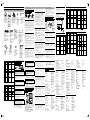 2
2


Alpine HCE-C105 El manual del propietario
- Categoría
- Sistemas de video del coche
- Tipo
- El manual del propietario
en otros idiomas
- français: Alpine HCE-C105 Le manuel du propriétaire
- italiano: Alpine HCE-C105 Manuale del proprietario
- English: Alpine HCE-C105 Owner's manual
- Deutsch: Alpine HCE-C105 Bedienungsanleitung
- svenska: Alpine HCE-C105 Bruksanvisning
Artículos relacionados
-
Alpine HCE-C105 Manual de usuario
-
Alpine HCE-C107D El manual del propietario
-
Alpine HCE-C117D El manual del propietario
-
-
-
Alpine HCE-C157D El manual del propietario
-
Alpine HCE-C1100 El manual del propietario
-
-
-
Alpine HCE-C127D El manual del propietario