Broan 157 Guía de instalación
- Categoría
- Calentadores espaciales
- Tipo
- Guía de instalación

READ AND SAVE
THESE INSTRUCTIONS
MODEL 157
CEILING HEATER
LEA Y CONSERVE
ESTAS INSTRUCCIONES
INSTALLER: Leave This Manual With The Homeowner. HOMEOWNER: Use and Care Information on Page 3.
INSTALADOR: Deje este manual con el dueño de casa. DUEÑO DE CASA: Información del uso y mantenimiento en la página 3.
SAFETY NOTES
1. ALL ELECTRICAL WORK MUST BE DONE IN AC-
CORDANCE WITH LOCAL AND/OR NATIONAL
ELECTRICAL CODE AS APPLICABLE. FOR
SAFETY, THIS PRODUCT MUST BE GROUNDED.
IF YOU ARE UNFAMILIAR WITH METHODS OF
INSTALLING ELECTRICAL WIRING, SECURE THE
SERVICES OF A QUALIFIED ELECTRICIAN.
2. TURN OFF POWER AT SERVICE ENTRANCE BE-
FORE INSTALLING, WIRING OR SERVICING THIS
PRODUCT.
3. This product is designed for horizontal ceiling in-
stallation only. DO NOT MOUNT THIS PRODUCT
ON A WALL OR SLOPED CEILING.
4. Do not install heater closer than 12" to any adja-
cent vertical surface.
5. To avoid electrical shock:
• DO NOT install unit in a tub or shower enclo-
sure.
• NEVER place a switch where it can be reached
from a tub or shower.
6. Provide heater with a SEPARATE 15 AMP (mini-
mum), 120 VAC circuit.
7. DO NOT CONNECT HEATER TO DIMMER
SWITCH OR SPEED CONTROL.
8. To avoid motor bearing damage and noisy and/or
unbalanced impellers, keep drywall spray, con-
struction dust, etc. off power unit.
9. Please read specification label on product for fur-
ther information and requirements.
PLAN THE
INSTALLATION
This heater is intended to be used to supply supple-
mental heat from a ceiling location in new or existing
construction.
Choose a location where edge of heater will be at least
12" from any adjacent vertical surface.
The heater can be operated using an ON/OFF switch,
timer (Broan Model 59W/59V 60-Minute or Broan
Model 61W/61V 15-Minute Timer), or thermostat
(Broan Model 86W Line-Voltage Thermostat). Pur-
chase the control separately.
Plan to supply the heater with proper line voltage and
appropriate power cable for its maximum wattage rat-
ing.
The heater attaches directly to any standard 3½" and
4" round, or 4" octagonal ceiling electrical box.
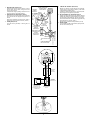
Follow these basic steps when installing this heater:
(FIG. 1)
• Mount electrical box in ceiling and attach power
cable to it.
• Connect wiring and fasten heater to electrical
box.
• Install grille.
INSTALLATION
1. Mount electrical box. (FIG. 2)
Position electrical box flush or slightly recessed
in ceiling and mount it securely.
2. Connect wiring. (FIG. 3)
Run electrical cable into box and secure with ap-
propriate connector. Allow 6" of wire inside box.
FIG. 1
HEATER
CALENTADOR
FIG. 2
FIG. 3
MODELO 157
CALENTADOR DE CIELO RASO
GRILLE SCREW
TORNILLO DE LA
REJILLA
CEILING
ELECTRICAL
BOX
CAJA
ELECTRICA DEL
CIELO RASO
CEILING
JOIST
VIGA DEL
CIELO RASO
DRYWALL
PARED DE YESO
INSTRUCCIONES DE
SEGURIDAD
1. TODO EL TRABAJO ELECTRICO DEBE REALIZARSE
DE ACUERDO CON LOS CODIGOS ELECTRICOS
LOCALES Y/O NACIONALES CORRESPONDIENTES.
PARA SU SEGURIDAD, ESTE PRODUCTO DEBE
SER CONECTADO A TIERRA. SI USTED NO ESTA
FAMILIARIZADO CON LOS METODOS DE
INSTALACION DEL CABLEADO ELECTRICO,
OBTENGA LOS SERVICIOS DE UN ELECTRICISTA
COMPETENTE.
2. CORTE LA ENERGIA EN LA ENTRADA DE SERVICIO
ANTES DE INSTALAR, CONECTAR O DAR SERVICIO
A ESTE PRODUCTO.
3. Este producto ha sido diseñado para instalación en cielo
raso horizontal solamente. NO MONTE ESTE
PRODUCTO EN UNA PARED O CIELO RASO
INCLINADO.
4. No instale el calentador a menos de 30,48 cm (12 pulg.)
de alguna superficie vertical adyacente.
5. Para evitar golpe eléctrico:
• NO instale la unidad en una bañera o recinto de ducha.
• NUNCA coloque un interruptor en un lugar que pueda
ser alcanzado desde una bañera o ducha.
6. Proporcione al calentador un circuito SEPARADO de 15
AMP (mínimo), 120 VCA.
7. NO CONECTE EL CALENTADOR A UN VARIADOR DE
LUZ O A UN CONTROL DE VELOCIDAD.
8. Para evitar daños al cojinete del motor e impulsores
ruidosos y/o desequilibrados, mantenga la unidad de
energía lejos de rocíos de yeso, polvo de construcción,
etc.
9. Para más información y requisitos, lea la etiqueta de
especificación sobre el producto.
PLANIFICACION DE LA
INSTALACION
Este calentador ha sido diseñado para proporcionar
calefacción adicional desde el cielo raso en una
construcción nueva o una ya existente.
Escoja un lugar en que el borde del calentador se
encuentre por lo menos a 30,48 cm (12 pulg.) de cualquier
superficie vertical adyacente.
Para el funcionamiento de este calentador se puede usar
un interruptor ON/OFF (ENCENDIDO/APAGADO),
temporizador (Broan Modelo 59W/59V de 60 minutos, o
temporizador Broan Modelo 61W/61V de 15 minutos), o
termostato (Broan Modelo 86W de tensión de línea).
Adquiera el control en forma separada.
Proporcione al calentador la tensión de línea y cable de
energía eléctrica correctos para su vatiaje maximo.
El calentador se conecta directamente a una caja eléctrica
rondo estándar de cielo raso de 8,89 cm y 10,16 cm (3½
o 4 pulg.), o una caja eléctrica octagonal estándar de cielo
raso de 10,16 cm (3½ o 4 pulg.).
Al instalar este calentador, siga estos pasos básicos:
(FIG. 1)
• Monte la caja eléctrica en el cielo raso y conecte el cable
de energía eléctrica a la misma.
• Conecte el cableado y fije el calentador a la caja eléctrica.
• Instale la rejilla.
INSTALACION
1. Monte la caja eléctrica. (FIG. 2)
Coloque la caja eléctrica a nivel o un poco hacia adentro
en el cielo raso y fíjela de forma segura.
2. Conecte el cableado. (FIG. 3)
Coloque el cable eléctrico en la caja y asegúrelo con el
conector apropiado. Deje 15,24 cm (6 pulg.) de cable
dentro de la caja.

FIG. 4
FIG. 5
FIG. 6
GROUND TIERRA
BLACK
NEGRO
120 VCA 60 HZ LINE
IN
LINEA DE ENTRADA
DE 120 VCA 60
HZ
GROUND
SCREW
TORNILLO
DE TIERRA
GREEN OR BARE WIRE
ALAMBRE VERDE
O DESCUBIERTO
WHITE
BLANCO
BLACK
NEGRO
SWITCH BOX
CAJA DEL
INTERRUPTOR
TOGGLE SWITCH
TIMER OR
THERMOSTAT
TEMPORIZADOR DE
INTERRUPTOR DE
PALANCA
ACODILLADA O
TERMOSTATO
WHITE BLANCO
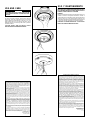
3. Wire the heater. (FIGS. 4 & 5)
Attach electrical power cable to heater. Connect
black to black, white to white, and green or bare
wire to ground screw.
Complete the wiring by adding a wall control. Fol-
low the pictorial or schematic diagram.
4. Attach heater to electrical box. (FIG. 6)
Tuck wires up into electrical box. Fit screw heads
from electrical box into appropriate keyholes, as
shown.
Twist heater clockwise to hold it in place. (FIG. 7)
Tighten two (2) electrical box screws. (FIG. 8)
5. Install grille. (FIG. 9)
Use grille screw (provided) to attach grille, as
shown.
2
3. Cableado del calentador. (FIGS. 4 & 5)
Enchufe el cable de energía eléctrica al calentador.
Conecte negro a negro, blanco a blanco, y cable verde
o descubierto al tornillo de tierra.
Complete el cableado agregando un control de pared.
Siga el diagrama de figuras o esquemático.
4. Fije el calentador a la caja eléctrica. (FIG. 6)
Coloque los cables dentro de la caja eléctrica. Meta las
cabezas de tornillo para la caja eléctrica en los ojos de
las cerraduras correspondientes, tal como se muestra.
Gire el al calentador en el sentido de las agujas del reloj
para mantenerlo en su lugar. (FIG. 7)
Apriete dos (2) tornillos de la caja eléctrica. (FIG. 8)
5. Instale la rejilla.
Use el tornillo de rejilla (proporcionado) para fijar ésta,
tal como se muestra. (FIG. 9)
M
HEATING ELEMENT
ELEMENTO DE CALOR
BLACK
NEGRO
BLACK
NEGRO
GROUND / TIERRA
WHITE
BLANCO
BLACK
NEGRO
WHITE
BLANCO
GROUND
TIERRA
WHITE
BLANCO
120 VAC LINE IN
LINEA DE ENTRADA
120 VCA
SWITCH BOX
CAJA DE
INTERRUPTORES
TOGGLE SWITCH, TIMER,
OR THERMOSTAT
TEMPORIZADOR DE
INTERRUPTOR, DE
PALANCA ACODILLADA,
O TERMOSTATO
CEILING BOX
CAJA DE
CIELO RASO
THERMAL CUTOFF
TERMICA
INTERRUPTOR

GARANTIA BROAN LIMITADA POR UN AÑO
Broan garantiza al consumidor comprador original de sus productos que
dichos productos carecerán de defectos en materiales o en mano de obra
por un período de un año a partir de la fecha original de compra. NO
EXISTEN OTRAS GARANTIAS, NI EXPLICITAS NI IMPLICITAS,
INCLUYENDO, PERO NO LIMITADAS A, GARANTIAS IMPLICITAS DE
COMERCIALIZACION O APTITUD PARA UN PROPOSITO PARTICULAR.
Durante el período de un año, y a su propio criterio, Broan reparará o
reemplazará, sin costo alguno, cualquier producto o pieza que se encuentre
defectuosa bajo condiciones normales de servicio y uso.
ESTA GARANTIA NO SE APLICA A TUBOS Y ARRANCADORES DE
LAMPARAS FLUORESCENTES. Esta garantía no cubre (a) mantenimiento
y servicio normales ni (b) cualquier producto o piezas que hayan sido
utilizadas de forma errónea, negligente, que hayan tenido un accidente, o
que hayan sido reparadas o mantenidas incorrectamente (por otras
compañías que no sean Broan), instalación defectuosa, o instalación
contraria a las instrucciones de instalación recomendadas.
La duración de cualquier garantía implícita se limita a un período de un año
como se especifica en la garantía expresa. Algunos estados no permiten
limitaciones en cuanto al tiempo de expiración de una garantía implícita,
por lo que la limitación antes mencionada puede no corresponderle.
LA OBLIGACION DE BROAN DE REPARAR O REEMPLAZAR, SIGUIENDO
EL CRITERIO DE BROAN, DEBERA SER EL UNICO Y EXCLUSIVO
RECURSO LEGAL DEL COMPRADOR BAJO ESTA GARANTIA. BROAN
NO SERA RESPONSABLE POR DAÑOS INCIDENTALES,
CONSIGUIENTES, O POR DAÑOS ESPECIALES RESULTANTES A RAIZ
DEL USO O DESEMPEÑO DEL PRODUCTO.
Algunos estados no permiten la exclusión o limitación de daños incidentales
o consiguientes, por lo que la limitación antes mencionada puede no aplicarse
a usted.
Esta garantía le proporciona derechos legales específicos, y usted puede
también tener otros derechos, los cuales varían de estado a estado. Esta
garantía reemplaza todas las garantías anteriores.
Para tener derecho al servicio de garantía, usted debe (a) notificar a Broan
en la dirección que se menciona abajo o al teléfono:1-800-637-1453 en los
E.E. U.U., (b) dar el número del modelo y la identificación de la pieza, y (c)
describir la naturaleza de cualquier defecto en el producto o pieza. En el
momento de solicitar servicio cubierto por la garantía, usted debe presentar
comprobación de la fecha original de compra.
Broan-NuTone LLC
926 West State Street,
Hartford, WI 53027.
U.S.A.
USO Y MANTENIMIENTO
DESCONECTE EL SUMINISTRO DE ENERGÍA ELÉCTRICA
EN LA ENTRADA DE SERVICIO ANTES DE EFECTUAR LA
LIMPIEZA, O DAR SERVICIO A LA UNIDAD
LIMPIEZA
Para hace la limpieza del equipo del calentador, limpie con
cuidado a través de la rejilla del calentador, usando el
cepillo redondo en su aspiradora. Quite las acumulaciones
de polvo, pelusa, etc., que puedan impedir el flujo de aire
a través del calentador. Ese bloqueo disminuirá la eficiencia
y creará una posible condición de sobrecalentamiento.
CUIDADO: LAS PIEZAS METALICAS Y ELECTRICAS
NUNCA SE DEBEN SUMERGIR EN AGUA.
USE AND CARE
DISCONNECT ELECTRIC POWER SUPPLY AT SER-
VICE ENTRANCE BEFORE CLEANING OR SERVIC-
ING UNIT.
CLEANING
To clean the heater assembly, carefully clean through
heater grille, using the round brush tool on your vacuum
cleaner. Remove accumulations of dust, lint, etc., that
might impede the flow of air through the heater. Such
blockage will lower its efficiency and create a possible
overheat condition.
CAUTION: METAL AND ELECTRICAL PARTS
SHOULD NEVER BE IMMERSED IN WATER.
3
CAUTION
FIG. 7
FIG. 8
FIG. 9
BROAN ONE YEAR LIMITED WARRANTY
Broan warrants to the original consumer purchaser of its products that
such products will be free from defects in materials or workmanship for a
period of one year from the date of original purchase. THERE ARE NO
OTHER WARRANTIES, EXPRESS OR IMPLIED, INCLUDING, BUT NOT
LIMITED TO, IMPLIED WARRANTIES OF MERCHANTABILITY OR FIT-
NESS FOR A PARTICULAR PURPOSE.
During this one-year period, Broan will, at its option, repair or replace,
without charge, any product or part which is found to be defective under
normal use and service.
THIS WARRANTY DOES NOT EXTEND TO FLUORESCENT LAMP
STARTERS AND TUBES. This warranty does not cover (a) normal main-
tenance and service or (b) any products or parts which have been sub-
ject to misuse, negligence, accident, improper maintenance or repair
(other than by Broan), faulty installation or installation contrary to recom-
mended installation instructions.
The duration of an implied warranty is limited to the one-year period as
specified for the express warranty. Some states do not allow limitation
on how long an implied warranty lasts, so the above limitation may not
apply to you.
BROAN’S OBLIGATION TO REPAIR OR REPLACE, AT BROAN’S OP-
TION, SHALL BE THE PURCHASER’S SOLE AND EXCLUSIVE REM-
EDY UNDER THIS WARRANTY. BROAN SHALL NOT BE LIABLE FOR
INCIDENTAL, CONSEQUENTIAL OR SPECIAL DAMAGES ARISING
OUT OF OR IN CONNECTION WITH PRODUCT USE OR PERFOR-
MANCE. Some states do not allow the exclusion or limitation of inciden-
tal or consequential damages, so the above limitation may not apply to
you.
This warranty gives you specific legal rights, and you may also have
other rights, which vary from state to state. This warranty supersedes all
prior warranties.
To qualify for warranty service, you must (a) notify Broan at the address
stated below or telephone: 1-800-637-1453, (b) give the model number
and part identification and (c) describe the nature of any defect in the
product or part. At the time of requesting warranty service, you must
present evidence of the original purchase date.
Broan-NuTone LLC
926 West State Street,
Hartford, WI 53027

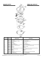
SERVICE PARTS
MODEL 157
PIEZAS DE SERVICIO
MODELO 157
Broan-NuTone LLC, 926 West State Street, Hartford, WI 53027 (1-800-637-1453)
99042185F
➘➘
➘➘
➘
20
➘➘
➘➘
➘
5
2
➘➘
➘➘
➘
➘➘
➘➘
➘
1
➙➙
➙➙
➙
3
➙➙
➙➙
➙
7
➙➙
➙➙
➙9
➙➙
➙➙
➙21
➙➙
➙➙
➙
➙➙
➙➙
➙
6
8
➙➙
➙➙
➙
11
➙➙
➙➙
➙
12
➙➙
➙➙
➙
10
➙➙
➙➙
➙
13
➙➙
➙➙
➙
14
➙➙
➙➙
➙
15
➙➙
➙➙
➙
4
➙➙
➙➙
➙
16
➙➙
➙➙
➙
17
➙➙
➙➙
➙
18
➙➙
➙➙
➙
19
➙➙
➙➙
➙
9
➙➙
➙➙
➙
14
Encargue piezas de servicio por "NO. PIEZ" -no por
"NO. CODIGO".
Order replacement parts by "PART NO." - NOT by KEY NO."
KEY NO. PART NO.
NO. CODIGO NO. PIEZ DESCRIPTION DESCRIPION
1 99150611 Green Ground Screw, #8B-18 x 3/8" Hex Hd. Tornillo Verde Tierra #8B-18 x 3/8" Cabeza Hexagonal
2 04200-14 #8-32 Hex Nut w/serrated Washer (2 Req.) #8-32 Tuerca Hexagonal con Arandela Estriada (Necesita 2)
3 05100-13 Cup Washer Arandela Acopada
4 04126-00 #8B Sheet Metal Nut - "U" Type #8B Tuerca de Chapa - En "U"
5 98008740 Ceiling Pan Collar de Techo
6 02159-00 Bushing Buje
7 99270721 Terminal Block Bloque Terminal
8 02144-01 Black Wire Assembly Haz de Alambres Negros
9 99160313 #6-32 x ¼" Pan Hd. Mach. Screw (4 Req.) #6-32 x ¼" Tornillo para Metales de Cabeza Chata (Necesita4)
10 99150527 #8B-18 x ½" PH Pan Hd. Screw #8B-18 x ½" PH Tornillo de Cabeza Chata
11 99080437 Motor Motor
12 06116-00 Fan Blade Aspa de Ventilador
13 98008741 Reflector Reflector
14 99150478 #8B-18 x 3/8" PH Truss Hd. Screw (6 Req.) #8B-18 x 3/8" Tornillo de Cabez Segmentada (Necesita 6)
15 98008742 Element Support (3 Req.) Soporte de Elemento (Necesita 3)
16 99270744 Element Elemento
17 25045-00 Grille Rejilla
18 99090680 Nameplate Plaquita
19 99150491 #8B-18 x 3/8" Phillips Pan Hd. Screw #8B-18 x 3/8" Tornillo de Cabez Chata Phillips
20 06317-00 Installation Hook Gancho para Instalación
21 97013088 White Wire Assembly Haz de Alambres Blancos
Transcripción de documentos
MODEL 157 CEILING HEATER MODELO 157 CALENTADOR DE CIELO RASO READ AND SAVE THESE INSTRUCTIONS LEA Y CONSERVE ESTAS INSTRUCCIONES SAFETY NOTES INSTRUCCIONES DE SEGURIDAD 1. ALL ELECTRICAL WORK MUST BE DONE IN ACCORDANCE WITH LOCAL AND/OR NATIONAL ELECTRICAL CODE AS APPLICABLE. FOR SAFETY, THIS PRODUCT MUST BE GROUNDED. IF YOU ARE UNFAMILIAR WITH METHODS OF INSTALLING ELECTRICAL WIRING, SECURE THE SERVICES OF A QUALIFIED ELECTRICIAN. 2. TURN OFF POWER AT SERVICE ENTRANCE BEFORE INSTALLING, WIRING OR SERVICING THIS PRODUCT. 3. This product is designed for horizontal ceiling installation only. DO NOT MOUNT THIS PRODUCT ON A WALL OR SLOPED CEILING. 4. Do not install heater closer than 12" to any adjacent vertical surface. 5. To avoid electrical shock: • DO NOT install unit in a tub or shower enclosure. • NEVER place a switch where it can be reached from a tub or shower. 6. Provide heater with a SEPARATE 15 AMP (minimum), 120 VAC circuit. 7. DO NOT CONNECT HEATER TO DIMMER SWITCH OR SPEED CONTROL. 8. To avoid motor bearing damage and noisy and/or unbalanced impellers, keep drywall spray, construction dust, etc. off power unit. 9. Please read specification label on product for further information and requirements. PLAN THE INSTALLATION This heater is intended to be used to supply supplemental heat from a ceiling location in new or existing construction. Choose a location where edge of heater will be at least 12" from any adjacent vertical surface. The heater can be operated using an ON/OFF switch, timer (Broan Model 59W/59V 60-Minute or Broan Model 61W/61V 15-Minute Timer), or thermostat (Broan Model 86W Line-Voltage Thermostat). Purchase the control separately. Plan to supply the heater with proper line voltage and appropriate power cable for its maximum wattage rating. The heater attaches directly to any standard 3½" and 4" round, or 4" octagonal ceiling electrical box. Follow these basic steps when installing this heater: (FIG. 1) • Mount electrical box in ceiling and attach power cable to it. • Connect wiring and fasten heater to electrical box. • Install grille. CEILING ELECTRICAL BOX CAJA ELECTRICA DEL DRYWALL CIELO RASO PARED DE YESO FIG. 1 PLANIFICACION DE LA INSTALACION HEATER CALENTADOR GRILLE SCREW TORNILLO DE LA REJILLA FIG. 2 INSTALLATION 1. Mount electrical box. (FIG. 2) Position electrical box flush or slightly recessed in ceiling and mount it securely. 2. Connect wiring. (FIG. 3) Run electrical cable into box and secure with appropriate connector. Allow 6" of wire inside box. CEILING JOIST VIGA DEL CIELO RASO FIG. 3 1. TODO EL TRABAJO ELECTRICO DEBE REALIZARSE DE ACUERDO CON LOS CODIGOS ELECTRICOS LOCALES Y/O NACIONALES CORRESPONDIENTES. PARA SU SEGURIDAD, ESTE PRODUCTO DEBE SER CONECTADO A TIERRA. SI USTED NO ESTA FAMILIARIZADO CON LOS METODOS DE INSTALACION DEL CABLEADO ELECTRICO, OBTENGA LOS SERVICIOS DE UN ELECTRICISTA COMPETENTE. 2. CORTE LA ENERGIA EN LA ENTRADA DE SERVICIO ANTES DE INSTALAR, CONECTAR O DAR SERVICIO A ESTE PRODUCTO. 3. Este producto ha sido diseñado para instalación en cielo raso horizontal solamente. NO MONTE ESTE PRODUCTO EN UNA PARED O CIELO RASO INCLINADO. 4. No instale el calentador a menos de 30,48 cm (12 pulg.) de alguna superficie vertical adyacente. 5. Para evitar golpe eléctrico: • NO instale la unidad en una bañera o recinto de ducha. • NUNCA coloque un interruptor en un lugar que pueda ser alcanzado desde una bañera o ducha. 6. Proporcione al calentador un circuito SEPARADO de 15 AMP (mínimo), 120 VCA. 7. NO CONECTE EL CALENTADOR A UN VARIADOR DE LUZ O A UN CONTROL DE VELOCIDAD. 8. Para evitar daños al cojinete del motor e impulsores ruidosos y/o desequilibrados, mantenga la unidad de energía lejos de rocíos de yeso, polvo de construcción, etc. 9. Para más información y requisitos, lea la etiqueta de especificación sobre el producto. Este calentador ha sido diseñado para proporcionar calefacción adicional desde el cielo raso en una construcción nueva o una ya existente. Escoja un lugar en que el borde del calentador se encuentre por lo menos a 30,48 cm (12 pulg.) de cualquier superficie vertical adyacente. Para el funcionamiento de este calentador se puede usar un interruptor ON/OFF (ENCENDIDO/APAGADO), temporizador (Broan Modelo 59W/59V de 60 minutos, o temporizador Broan Modelo 61W/61V de 15 minutos), o termostato (Broan Modelo 86W de tensión de línea). Adquiera el control en forma separada. Proporcione al calentador la tensión de línea y cable de energía eléctrica correctos para su vatiaje maximo. El calentador se conecta directamente a una caja eléctrica rondo estándar de cielo raso de 8,89 cm y 10,16 cm (3½ o 4 pulg.), o una caja eléctrica octagonal estándar de cielo raso de 10,16 cm (3½ o 4 pulg.). Al instalar este calentador, siga estos pasos básicos: (FIG. 1) • Monte la caja eléctrica en el cielo raso y conecte el cable de energía eléctrica a la misma. • Conecte el cableado y fije el calentador a la caja eléctrica. • Instale la rejilla. INSTALACION 1. Monte la caja eléctrica. (FIG. 2) Coloque la caja eléctrica a nivel o un poco hacia adentro en el cielo raso y fíjela de forma segura. 2. Conecte el cableado. (FIG. 3) Coloque el cable eléctrico en la caja y asegúrelo con el conector apropiado. Deje 15,24 cm (6 pulg.) de cable dentro de la caja. INSTALLER: Leave This Manual With The Homeowner. HOMEOWNER: Use and Care Information on Page 3. INSTALADOR: Deje este manual con el dueño de casa. DUEÑO DE CASA: Información del uso y mantenimiento en la página 3. FIG. 4 3. Cableado del calentador. (FIGS. 4 & 5) Enchufe el cable de energía eléctrica al calentador. Conecte negro a negro, blanco a blanco, y cable verde o descubierto al tornillo de tierra. Complete el cableado agregando un control de pared. Siga el diagrama de figuras o esquemático. 4. Fije el calentador a la caja eléctrica. (FIG. 6) Coloque los cables dentro de la caja eléctrica. Meta las cabezas de tornillo para la caja eléctrica en los ojos de las cerraduras correspondientes, tal como se muestra. Gire el al calentador en el sentido de las agujas del reloj para mantenerlo en su lugar. (FIG. 7) Apriete dos (2) tornillos de la caja eléctrica. (FIG. 8) 5. Instale la rejilla. Use el tornillo de rejilla (proporcionado) para fijar ésta, tal como se muestra. (FIG. 9) GREEN OR BARE WIRE ALAMBRE VERDE O DESCUBIERTO GROUND SCREW TORNILLO WHITE DE TIERRA BLANCO BLACK NEGRO TOGGLE SWITCH TIMER OR THERMOSTAT TEMPORIZADOR DE INTERRUPTOR DE PALANCA ACODILLADA O TERMOSTATO GROUND TIERRA BLACK NEGRO 120 VCA 60 HZ LINE IN LINEA DE ENTRADA DE 120 VCA 60 HZ WHITE BLANCO SWITCH BOX CAJA DEL INTERRUPTOR FIG. 5 M HEATING ELEMENT ELEMENTO DE CALOR WHITE BLANCO BLACK CEILING BOX CAJA DE CIELO RASO BLACK NEGRO TOGGLE SWITCH, TIMER, OR THERMOSTAT TEMPORIZADOR DE INTERRUPTOR, DE PALANCA ACODILLADA, O TERMOSTATO WHITE BLANCO BLACK NEGRO WHITE BLANCO GROUND TIERRA NEGRO THERMAL CUTOFF TERMICA INTERRUPTOR GROUND / TIERRA 3. Wire the heater. (FIGS. 4 & 5) Attach electrical power cable to heater. Connect black to black, white to white, and green or bare wire to ground screw. Complete the wiring by adding a wall control. Follow the pictorial or schematic diagram. 4. Attach heater to electrical box. (FIG. 6) Tuck wires up into electrical box. Fit screw heads from electrical box into appropriate keyholes, as shown. Twist heater clockwise to hold it in place. (FIG. 7) Tighten two (2) electrical box screws. (FIG. 8) 5. Install grille. (FIG. 9) Use grille screw (provided) to attach grille, as shown. 120 VAC LINE IN LINEA DE ENTRADA 120 VCA FIG. 6 2 SWITCH BOX CAJA DE INTERRUPTORES USE AND CARE USO Y MANTENIMIENTO FIG. 7 DESCONECTE EL SUMINISTRO DE ENERGÍA ELÉCTRICA EN LA ENTRADA DE SERVICIO ANTES DE EFECTUAR LA LIMPIEZA, O DAR SERVICIO A LA UNIDAD CAUTION DISCONNECT ELECTRIC POWER SUPPLY AT SERVICE ENTRANCE BEFORE CLEANING OR SERVICING UNIT. LIMPIEZA Para hace la limpieza del equipo del calentador, limpie con cuidado a través de la rejilla del calentador, usando el cepillo redondo en su aspiradora. Quite las acumulaciones de polvo, pelusa, etc., que puedan impedir el flujo de aire a través del calentador. Ese bloqueo disminuirá la eficiencia y creará una posible condición de sobrecalentamiento. CUIDADO: LAS PIEZAS METALICAS Y ELECTRICAS NUNCA SE DEBEN SUMERGIR EN AGUA. CLEANING To clean the heater assembly, carefully clean through heater grille, using the round brush tool on your vacuum cleaner. Remove accumulations of dust, lint, etc., that might impede the flow of air through the heater. Such blockage will lower its efficiency and create a possible overheat condition. CAUTION: METAL AND ELECTRICAL PARTS SHOULD NEVER BE IMMERSED IN WATER. FIG. 8 FIG. 9 BROAN ONE YEAR LIMITED WARRANTY Broan warrants to the original consumer purchaser of its products that such products will be free from defects in materials or workmanship for a period of one year from the date of original purchase. THERE ARE NO OTHER WARRANTIES, EXPRESS OR IMPLIED, INCLUDING, BUT NOT LIMITED TO, IMPLIED WARRANTIES OF MERCHANTABILITY OR FITNESS FOR A PARTICULAR PURPOSE. During this one-year period, Broan will, at its option, repair or replace, without charge, any product or part which is found to be defective under normal use and service. THIS WARRANTY DOES NOT EXTEND TO FLUORESCENT LAMP STARTERS AND TUBES. This warranty does not cover (a) normal maintenance and service or (b) any products or parts which have been subject to misuse, negligence, accident, improper maintenance or repair (other than by Broan), faulty installation or installation contrary to recommended installation instructions. The duration of an implied warranty is limited to the one-year period as specified for the express warranty. Some states do not allow limitation on how long an implied warranty lasts, so the above limitation may not apply to you. BROAN’S OBLIGATION TO REPAIR OR REPLACE, AT BROAN’S OPTION, SHALL BE THE PURCHASER’S SOLE AND EXCLUSIVE REMEDY UNDER THIS WARRANTY. BROAN SHALL NOT BE LIABLE FOR INCIDENTAL, CONSEQUENTIAL OR SPECIAL DAMAGES ARISING OUT OF OR IN CONNECTION WITH PRODUCT USE OR PERFORMANCE. Some states do not allow the exclusion or limitation of incidental or consequential damages, so the above limitation may not apply to you. This warranty gives you specific legal rights, and you may also have other rights, which vary from state to state. This warranty supersedes all prior warranties. To qualify for warranty service, you must (a) notify Broan at the address stated below or telephone: 1-800-637-1453, (b) give the model number and part identification and (c) describe the nature of any defect in the product or part. At the time of requesting warranty service, you must present evidence of the original purchase date. Broan-NuTone LLC 926 West State Street, Hartford, WI 53027 GARANTIA BROAN LIMITADA POR UN AÑO Broan garantiza al consumidor comprador original de sus productos que dichos productos carecerán de defectos en materiales o en mano de obra por un período de un año a partir de la fecha original de compra. NO EXISTEN OTRAS GARANTIAS, NI EXPLICITAS NI IMPLICITAS, INCLUYENDO, PERO NO LIMITADAS A, GARANTIAS IMPLICITAS DE COMERCIALIZACION O APTITUD PARA UN PROPOSITO PARTICULAR. Durante el período de un año, y a su propio criterio, Broan reparará o reemplazará, sin costo alguno, cualquier producto o pieza que se encuentre defectuosa bajo condiciones normales de servicio y uso. ESTA GARANTIA NO SE APLICA A TUBOS Y ARRANCADORES DE LAMPARAS FLUORESCENTES. Esta garantía no cubre (a) mantenimiento y servicio normales ni (b) cualquier producto o piezas que hayan sido utilizadas de forma errónea, negligente, que hayan tenido un accidente, o que hayan sido reparadas o mantenidas incorrectamente (por otras compañías que no sean Broan), instalación defectuosa, o instalación contraria a las instrucciones de instalación recomendadas. La duración de cualquier garantía implícita se limita a un período de un año como se especifica en la garantía expresa. Algunos estados no permiten limitaciones en cuanto al tiempo de expiración de una garantía implícita, por lo que la limitación antes mencionada puede no corresponderle. LA OBLIGACION DE BROAN DE REPARAR O REEMPLAZAR, SIGUIENDO EL CRITERIO DE BROAN, DEBERA SER EL UNICO Y EXCLUSIVO RECURSO LEGAL DEL COMPRADOR BAJO ESTA GARANTIA. BROAN NO SERA RESPONSABLE POR DAÑOS INCIDENTALES, CONSIGUIENTES, O POR DAÑOS ESPECIALES RESULTANTES A RAIZ DEL USO O DESEMPEÑO DEL PRODUCTO. Algunos estados no permiten la exclusión o limitación de daños incidentales o consiguientes, por lo que la limitación antes mencionada puede no aplicarse a usted. Esta garantía le proporciona derechos legales específicos, y usted puede también tener otros derechos, los cuales varían de estado a estado. Esta garantía reemplaza todas las garantías anteriores. Para tener derecho al servicio de garantía, usted debe (a) notificar a Broan en la dirección que se menciona abajo o al teléfono:1-800-637-1453 en los E.E. U.U., (b) dar el número del modelo y la identificación de la pieza, y (c) describir la naturaleza de cualquier defecto en el producto o pieza. En el momento de solicitar servicio cubierto por la garantía, usted debe presentar comprobación de la fecha original de compra. Broan-NuTone LLC 926 West State Street, Hartford, WI 53027. U.S.A. 3 SERVICE PARTS 1 ➘ ➘ MODEL 157 PIEZAS DE SERVICIO 2 5 ➙ ➙ ➙ 10 6 11 8 ➙ 9➙ ➙ 12 13 ➙ 21 ➙ ➙ ➙ 4 ➙ ➙ ➙ ➙ 1 2 3 4 5 6 7 8 9 10 11 12 13 14 15 16 17 18 19 20 21 14 16 ➙ KEY NO. 14 15 ➙ 9➙ NO. CODIGO MODELO 157 ➘ 7➙ 20 ➘ 3➙ 17 18 19 PART NO. NO. PIEZ 99150611 04200-14 05100-13 04126-00 98008740 02159-00 99270721 02144-01 99160313 99150527 99080437 06116-00 98008741 99150478 98008742 99270744 25045-00 99090680 99150491 06317-00 97013088 DESCRIPTION Green Ground Screw, #8B-18 x 3/8" Hex Hd. #8-32 Hex Nut w/serrated Washer (2 Req.) Cup Washer #8B Sheet Metal Nut - "U" Type Ceiling Pan Bushing Terminal Block Black Wire Assembly #6-32 x ¼" Pan Hd. Mach. Screw (4 Req.) #8B-18 x ½" PH Pan Hd. Screw Motor Fan Blade Reflector #8B-18 x 3/8" PH Truss Hd. Screw (6 Req.) Element Support (3 Req.) Element Grille Nameplate #8B-18 x 3/8" Phillips Pan Hd. Screw Installation Hook White Wire Assembly DESCRIPION Tornillo Verde Tierra #8B-18 x 3/8" Cabeza Hexagonal #8-32 Tuerca Hexagonal con Arandela Estriada (Necesita 2) Arandela Acopada #8B Tuerca de Chapa - En "U" Collar de Techo Buje Bloque Terminal Haz de Alambres Negros #6-32 x ¼" Tornillo para Metales de Cabeza Chata (Necesita4) #8B-18 x ½" PH Tornillo de Cabeza Chata Motor Aspa de Ventilador Reflector #8B-18 x 3/8" Tornillo de Cabez Segmentada (Necesita 6) Soporte de Elemento (Necesita 3) Elemento Rejilla Plaquita #8B-18 x 3/8" Tornillo de Cabez Chata Phillips Gancho para Instalación Haz de Alambres Blancos Order replacement parts by "PART NO." - NOT by KEY NO." Encargue piezas de servicio por "NO. PIEZ" -no por "NO. CODIGO". Broan-NuTone LLC, 926 West State Street, Hartford, WI 53027 (1-800-637-1453) 99042185F-
 1
1
-
 2
2
-
 3
3
-
 4
4


Broan 157 Guía de instalación
- Categoría
- Calentadores espaciales
- Tipo
- Guía de instalación
en otros idiomas
- English: Broan 157 Installation guide