Questions, problems, missing parts? Before returning to your retailer, call
our customer service department at 1-866-573-0674, 7:30 am - 4:15 pm EST,
Monday through Friday or email customerservice@usaprocom.com
FIB100 BLOWER ACCESSORY
INSTALLATION INSTRUCTIONS
WARNING: ELECTRICAL GROUNDING INSTRUCTIONS This
appliance is equipped with a three-prong (grounding) plug for your
protection against shock hazard and should be plugged directly into
a properly grounded three-prong receptacle.
Spanish/Español
Page 13

www.usaprocom.com
200016-01D2
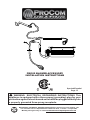
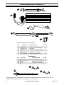
Parts included with this kit
Item Part No. Description Qty
A XB001-01 Power Cord 1
B XB002-01F Blower 1
C XB003-01 Temperature Sensor 1
D XB004-01F Connect Wire 1
E PF06-0400-A Rocker Switch 1
PACKAGE CONTENTS
A
B
C
AA
BB
CC
D
E
Hardware
Item Part No. Description Qty
AA GB/T 845-4.2*9.5F M4.2x8 Screw 6
BB VL057-01 Cable Tie 6
CC 4*8 M4.0x8 Screw 1
If any of these pieces are missing or damaged call ProCom Heating, Inc. at 1-866-573-0674
for referral information.

www.usaprocom.com
3200016-01D
SAFETY
IMPORTANT: Read all instruc-
tions and warnings carefully
before starting installation. Fail-
ure to follow these instructions
may result in a possible electric
shock, re hazard and will void
the warranty.
• Read all instructions before using this ap-
pliance.
• If possible always unplug this appliance
when not in use.
• Do not operate any heater with a damaged
cord or plug or after the appliance malfunc-
tions, has been dropped or damaged in any
manner.
• Any repairs to this appliance should be
carried out by a qualied service person.
• Under no circumstances should this ap-
pliance be modied. Parts having to be
removed for servicing must be replaced
prior to operating this appliance again.
• Do not use outdoors.
• Never locate this appliance where it may
fall into a bathtub or other water container.
• Do not run cord under carpeting. Do not
cover cord with throw rugs, runners or the
like. Arrange cord away from trafc areas
and where it will not be tripped over.
• To disconnect this appliance, turn controls
to the off position, then remove plug from
outlet.
• Connect to properly grounded outlets only.
• This appliance, when installed must be
electrically grounded in accordance with
local codes, with the current CSA C22.1
Canadian Electrical Codes or for USA
installations, follow local codes and the
National Electric Code, ANSI/NFPA No. 70.
• Do not insert or allow foreign objects to
enter any ventilation or exhaust opening
as this may cause an electric shock, re
or damage the appliance.
• To prevent possible re, do not block air
intakes or exhaust in any manner.
• Use this appliance only as described in this
manual. Any other use not recommended
by the manufacturer may cause re, electric
shock or injury to persons.
• Avoid the use of an extension cord because
of the risk of overheating the cord and the
risk of re. Extension cords are for tempo-
rary use only. If an extension cord must be
used, it must be UL/CSA certied, rated
at 10A (1250W), 125V maximum with 16
AWG minimum and constructed of two
current carrying conductors with ground. A
heavy duty extension cord with the shortest
length possible for the connection is recom-
mended and must not be longer than 50 ft.
(15.2 m). Do not coil or cover the extension
cord.

www.usaprocom.com
200016-01D4
PREPARATION
Tools Required
• Phillips Screwdriver
• Wire Cutter
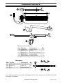
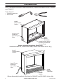
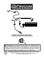
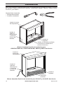
Blower Assembly Installation Position for PC32VFC and PC36VFC Series Only
Install
Rocker
Switch
Install Rocker Switch
(Controls are Behind
Access Door)
Install
Blower
Assembly
Install
Blower
Assembly
Install
Temperature
Sensor
Install
Temperature
Sensor
Blower Assembly Installation Position for
CRHFD28TCM-6-AU, CRHFD32RT-M-MO, FBD28 and FBD32 Series Only
Note: This blower contains assembly instructions for the following models and item numbers.
For the CRHFD28TCM-6-AU, CRHFD32RT-M-MO, FBD28 and FBD32 series, PC32VFC
and PC36VFC.
Install Power
Cord and
Grounding
Wire
Install Power
Cord and
Grounding
Wire

www.usaprocom.com
5200016-01D
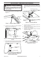
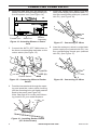
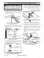
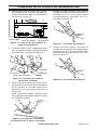
WARNING: Before installing
the blower, be certain to turn off
the unit, and allow time for unit
to cool down.
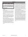
1. Remove upper rebox by unscrewing
left and right screws on the rebox (see
Figure 1).
Figure 1 - Remove Upper Firebox
Figure 2 - Remove Heat Insulation Board
Cover
Figure 3 - Attach Temperature Sensor to
Heat Insulation Board
Figure 4 - Attaching Wiring
2. Unscrew two screws on heat insulation
board cover (see Figure 2).
3. Afx temperature sensor to heat insulation
board cover with two M4.2X8 screws (AA).
4. Insert wires into the space between wire
protecting board and shell. Attach the
wires to the top cover with wire routing
clip.
Wire Routing Clip
Temperature
Sensor
Screw (AA)
Protecting
Board
INSTALLING TEMPERATURE SENSOR
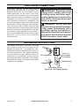
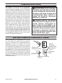
5. Connect wires to temperature sensor as
shown in Figure 5.
6. Reinstall heat installation board cover with
2 screws (see Figure 2).
7. Replace upper rebox using 2 screws
removed in step 1.
Figure 5 - Connecting Wires to
Temperature Sensor
Temperature
Sensor
Wiring

www.usaprocom.com
200016-01D6
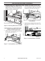
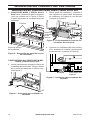
4. Attach blower with M4.0X8 screws (CC),
after manually installing it into slots, (see
Figure 9).
Figure 8 - Positioning Blower Assembly
to Shell Board
Figure 9 - Installing Blower Assembly
3. Set blower plane and attach to two brack-
ets of shell board. Make sure blower is
installed into the slots (see Figure 8).
Blower
Assembly
Install
Blower
into Slots
Screws
Blower Access Panel
Figure 7 - Inserting Blower into Fireplace
CRHFD28TCM-6-AU, CRHFD32RT-M-MO,
FBD28 and FBD32 Series Only
2. Insert blower into the bottom space of
burner pan. Pay attention not to touch
wires inside (see Figure 7).
Figure 6 - Removing Blower Access Panel
INSTALLING BLOWER ASSEMBLY
1. CRHFD32RT-M-MO and FBD32 Series
Only Remove 2 screws securing panel as
shown in Figure 6. Remove panel to gain
access to blower compartment.
CRHFD28TCM-6-AU, CRHFD32RT-M-MO, FBD28 and FBD32 Series Only

www.usaprocom.com
7200016-01D
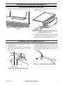
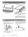
INSTALLING BLOWER ASSEMBLY
1. Remove blower access panel (see Fig-
ure 10).
Figure 10 - Removing Blower Access
Panel
Figure 11 - Attaching Blower Assembly to
Blower Access Panel
PC32VFC and PC36VFC Series Only
2. Mount blower onto blower access panel,
(see Figure 11).
3. Carefully insert blower and wiring through
access hole. Reinstall blower access
panel with screws removed in step 1.
Figure 12 - Installing Power Cord
Figure 13 - Attaching Grounding Wire
1. Insert power cord wires through hole in
side of rebox.
2. Attach the power cord to the replace
with three M4.2X8 screws (AA), (see
Figure 12).
AA
3. Install grounding terminal to the back wall
of rebox with 1) M4.2X8 screw (AA). The
hole for installing the screw is marked
with the grounding symbol as shown in
Figure 13.
AA
Power Cord
CONNECTING POWER SUPPLY

www.usaprocom.com
200016-01D8
Figure 14 - Attaching Blower to Power
Cord
4. Insert the male port from the blower as-
sembly into the corresponding female port
from the power cord, (see Figure 14).
Blower
Assembly
Female Port
Male Port
5. Connect the AUTO, OFF, MAN wires to
the three corresponding male tabs on the
rocker switch (see Figure 15).
AUTO
OFF (O)
MAN
Rocker Switch
Figure 15 - Connecting Wires to Rocker
Switch
Figure 16 - Installing Rocker Switch
(PC Series Shown)
Figure 17 - Connecting P1 Wires
Figure 18 - Connecting P2 Wires
6. Feed the harness back through the open-
ing and push the rocker switch housing
into the mounting hole until tightly seated
ush to the panel (see Figure 16).
Note: See page 4 for rocker switch hous-
ing location for your model replace.
MAN O AUTO
7. Insert the female port, which is on the
white power supply wire (marked with P1),
into the corresponding male port. (marked
with P1), (see Figure 18).
P1
P2
8. Insert the male port, which is on the black
power supply wire (marked with P2), into
the corresponding female port (marked
with P2), (see Figure 17).
CONNECTING POWER SUPPLY

www.usaprocom.com
9200016-01D
ELECTRICAL CONNECTION
A 15 amp, 120 Volt, 60 Hz circuit with a
properly grounded outlet is required. The
replace should be on a dedicated circuit.
Other appliances on the same circuit may
cause the circuit breaker to trip, or the fuse to
blow when the heater is in operation. Plan the
installation to avoid the use of an extension
cord. Extension cords are for temporary use
only. If an extension cord must be used, it must
be UL/CSA certied, rated at 10A (1250W),
125V maximum with 16 AWG minimum and
constructed of two current carrying conductors
with ground. A heavy duty extension cord with
the shortest length possible for the connec-
tion is recommended and must not be longer
than 50 ft. (15.2 m). Do not coil or cover the
extension cord.
WARNING: Electrical outlet
wiring must comply with local
building codes and other appli-
cable regulations to reduce the
risk of re, electrical shock and
injury to persons.
WARNING: Do not use this
replace if any part of it has been
under water. Immediately call a
qualied service technician to
inspect the replace and replace
any part of the electrical system
which has been under water.
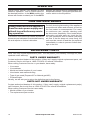
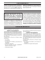
GROUNDING INSTRUCTIONS
This heater is for use on 120 volts. The cord
has a plug as shown at A in Figure 19. An
adapter as shown at C is available for con-
necting three-blade grounding-type plugs to
two-slot receptacles. The green grounding
lug extending from the adapter must be
connected to a permanent ground such as
a properly grounded outlet box. The adapter
should not be used if a three-slot grounded
receptacle is available.
Grounding Pin
Grounding Means
Metal Screw
Cover of
Grounded
Outlet Box
A
B
C
Adapter
Figure 19 - Grounding Options

www.usaprocom.com
200016-01D10
OPERATION
Using rocker switch, turn blower on and
check for operation. Turn on rocker switch to
the desired position. In the MAN position the
blower will remain constantly on. In the AUTO
position the blower will be controlled by the
temperature sensor. To stop the operation turn
rocker switch to the O position.
Note: Use only original replacement parts. This will protect your warranty coverage for parts
replaced under warranty.
PARTS UNDER WARRANTY
Contact authorized dealers of this product. If they can’t supply original replacement parts, call
Customer Service toll free at 1-866-573-0674 for referral information.
When calling Customer Service or your dealer, have ready:
• Your name
• Your address
• Model and serial number of your heater
• How heater was malfunctioning
• Type of gas used (Propane/LP or Natural gas/NG)
• Purchase date
Usually, we will ask you to return the defective part to the factory
PARTS NOT UNDER WARRANTY
Contact authorized dealers of this product. If they can’t supply original replacement part(s)
call Customer Service toll free at 1-866-573-0674 for referral information.
When calling Customer Service have ready:
• Model number of your heater
• The replacement part number
REPLACEMENT PARTS
CARE AND MAINTENANCE
Always disconnect the appliance
from the main power supply and
allow it to cool before any servic-
ing operation.
The motors used on the fan heater and ame
blower are pre-lubricated for extended bearing
life and require no further lubrication.
Periodic cleaning/vacuuming of the appliance
around the air intake and exhaust, as well as
the fan heater is recommended. For heavy
or continuous use, periodic cleaning must
be done more frequently. If the heater blows
alternating cold and warm air, check the fan
for free movement and for debris restricting
air ow. If the fan does not move freely, the
unit must be turned off and the fan replaced
immediately in order to prevent further dam-
age to the unit.

www.usaprocom.com
11200016-01D
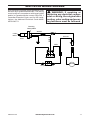
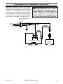
ELECTRICAL WIRING DIAGRAM
Any electrical re-wiring of this appliance must
be done by a qualied electrician. This wiring
must be done in accordance with local codes
and/or in Canada with the current CSA C22.1
Canadian Electrical Code, and for US instal-
lations, the National Electrical Code ANSI/
NFPA NO 70.
WARNING: If repairing or
replacing any electrical compo-
nent or wiring, the original wire
routing, color coding and secur-
ing locations must be followed.
Blower
BLACK
WHITE
GREEN
BLACK
RED
~120V
60Hz
Bushing
Strain Relief
Power
Cord
Rocker Switch
Temperature Sensor
AUTO OFF MAN

200016-01
Rev. D
01/16
REGISTER YOUR PRODUCT AT WWW.USAPROCOM.COM
IMPORTANT: We urge you to register your product within 10 days of date of installation, complete
with entire serial number which can be found on the rating plate. Please ll out the warranty infor-
mation above for your personal records. Retain this manual for future reference.
Always specify model and serial numbers when communicating with customer service.
We reserve the right to amend these specications at any time without notice. The only warranty applicable
is our standard written warranty. We make no other warranty, expressed or implied.
LIMITED WARRANTY
ProCom Heating, Inc. warrants this product to be free from defects in materials and components for ONE
(1) year from the date of rst purchase, provided that the product has been properly installed by a qualied
installer in accordance with all local codes and instructions furnished with the unit, operated and main-
tained in accordance with all applicable instructions. To make a claim under this warranty, the Bill of Sale
or cancelled check must be presented.
RESPONSIBILITY OF OWNER
This warranty is extended only to the original retail purchaser. This warranty covers the cost of part(s)
required to restore this heater to proper operating condition. Warranty part(s) MUST be obtained through
ProCom Heating, Inc. who will provide original factory replacement parts. Failure to use original factory
replacement parts voids this warranty. The heater MUST be installed by a qualied installer in accordance
with all local codes and instructions furnished with the unit.
WHAT IS NOT COVERED
This warranty does not apply to parts that are not in original condition because of normal wear and tear or
parts that fail or become damaged as a result of misuse, accidents, lack of proper maintenance or defects
caused by improper installation. Travel, diagnostic cost, labor, transportation and any and all such other
costs related to repairing a defective heater will be the responsibility of the owner.
TO THE FULL EXTENT ALLOWED BY THE LAW OF THE JURISDICTION THAT GOVERNS THE SALE
OF THE PRODUCT, THIS EXPRESS WARRANTY EXCLUDES ANY AND ALL OTHER EXPRESSED
WARRANTIES AND LIMITS THE DURATION OF ANY AND ALL IMPLIED WARRANTIES. INCLUDING
WARRANTIES OF MERCHANTABILITY AND FITNESS FOR A PARTICULAR PURPOSE TO ONE (1)
YEAR ON ALL COMPONENTS FROM THE DATE OF FIRST PURCHASE. PROCOM HEATING, INC.'S
LIABILITY IS HEREBY LIMITED TO THE PURCHASE PRICE OF THE PRODUCT AND PROCOM HEAT-
ING, INC. SHALL NOT BE LIABLE FOR ANY OTHER DAMAGES WHATSOEVER INCLUDING INDIRECT.
INCIDENTAL OR CONSEQUENTIAL DAMAGES.
Some states do not allow a limitation on how long an implied warranty lasts or an exclusion or limitation of
accidental or consequential damages, the above limitation on implied warranties, or exclusion or limitation
on damages may not apply to you.
This warranty gives you specic legal right, and you may also have other rights that vary from state to state.
WARRANTY
KEEP THIS WARRANTY
Model _______________________________
Serial No. ____________________________
Date Purchased _______________________
Keep receipt for warranty verication.
ProCom Heating, Inc.
Bowling Green, KY 42101
www.usaprocom.com
1-866-573-0674

¿Preguntas, problemas, piezas faltantes? Antes de volver a la tienda, llame a
nuestro Departamento de Servicio al Cliente al 1-866-573-0674, de lunes a viernes de
7:30 a.m. a 4:15 p.m., Hora del Centro, o envíe un correo electrónico a
customerservice@usaprocom.com.
FIB100 ACCESORIO SOPLADOR
INSTRUCCIONES DE INSTALACIÓN
ADVERTENCIA: INSTRUCCIONES PARA LA CONEXIÓN ELÉC-
TRICA A TIERRA Este aparato está equipado con un enchufe de tres
clavijas (con conexión a tierra) para protegerlo contra el riesgo de
descargas eléctricas y debe ser enchufado directamente a un toma-
corriente de tres patas con conexión a tierra receptáculo.

www.usaprocom.com
200016-01D14
Piezas incluidas con este equipo
Art. Pieza # Descripción Cant.
A XB001-01 Cable de alimentación 1
B XB002-01F Soplador 1
C XB003-01 Sensor de temperatura 1
D XB004-01F Cables conectores 1
E PF06-0400-A Interruptor oscilante 1
CONTENIDO DEL PAQUETE
A
B
C
AA
BB
D
E
Si alguna de estas piezas falta o está dañado llamada ProCom Calefacción, Inc. al
1-866-573-0674 para obtener información de referencia.
CC
Hardware
Art. Pieza # Descripción Cant.
AA GB/T 845-4.2*9.5F M4.2x9.5 Tornillo 6
BB VL057-01 Amarre de cable 6
CC 4*8 M4.2x9.5 Tornillo 1

www.usaprocom.com
15200016-01D
SEGURIDAD
IMPORTANTE: Lea con atención
todas las instrucciones y ad-
vertencias antes de comenzar
la instalación. Si no se siguen
las instrucciones, se puede
provocar una descarga eléctri-
ca o riesgo de incendio, lo que
anulará la garantía.
• Lea todas las instrucciones antes de usar
este electrodoméstico.
• Si es posible, siempre desenchufe este
electrodoméstico cuando no lo use.
• No opere ningún calentador con un cable
o enchufe dañados, o después de fallas
del mismo, de que se haya dejado caer o
dañado de cualquier forma.
• Toda reparación de este electrodoméstico
debe realizarla un técnico calicado.
• Bajo ninguna circunstancia se debe mo-
dicar este electrodoméstico. Las piezas
que se deben retirar para reparación se
deben reemplazar antes de volver a hacer
funcionar este electrodoméstico.
• No lo use en exteriores.
• Nunca coloque este calentador donde se
pueda caer dentro de una bañera u otro
contenedor de agua.
• No coloque el cable debajo de una al-
fombra. No cubra el cable con alfombras,
tapetes o similares. Coloque el cable lejos
de zonas de tránsito en donde nadie se
pueda tropezar y caer.
• Para desconectar este electrodoméstico,
gire los controles a la posición de apagado
y luego retire el enchufe del tomacorriente.
• Conecte sólo a tomacorrientes con la de-
bida puesta a tierra.
• Cuando está instalado, este electrodomés-
tico debe presentar una puesta eléctrica a
tierra conforme a los códigos locales, a los
Códigos de Electricidad de Canadá CSA
C22.1 o, para instalaciones en EE.UU.,
seguir los códigos locales y el Código
Nacional de Electricidad, ANSI/NFPA No.
70.
• No introduzca objetos extraños ni permita
que entren en las aberturas de escape o
ventilación, ya que pueden provocar des-
cargas eléctricas, incendios o daños en el
electrodoméstico.
• Para evitar incendios, no bloquee las entra-
das ni salidas de aire de ninguna manera.
• Utilice este electrodoméstico sólo como se
describe en este manual. Cualquier otro
uso no recomendado por el fabricante pue-
de causar incendios, descargas eléctricas
o lesiones personales.
• Evite utilizar extensiones eléctricas para
evitar riesgos de sobrecalentamiento y de
incendio. Las extensiones eléctricas son
sólo para uso temporal. De ser necesaria
una extensión eléctrica, ésta debe estar
certicada UL/CSA, clasicada como 10
A (1250 W), 125 V como máximo con 16
AWG como mínimo y fabricada con dos
conductores de corriente con puesta a tie-
rra. Se recomienda una extensión eléctrica
para trabajo pesado de la menor longitud
posible para la conexión, que no sobrepase
los 15,24 m (50 pies). No enrolle ni cubra
la extensión eléctrica.

www.usaprocom.com
200016-01D16
PREPARACIÓN
Herramientas necesarias
• Phillips destornillador
• Cortador de alambre
Nota: Este soplador contiene instrucciones de montaje de los siguientes modelos y números
de artículos. Para el CRHFD28TCM-6-AU, CRHFD32RT-M-MO, FBD28 y FBD32 series,
PC32VFC y PC36VFC.
Instale el
interruptor
oscilante
Instale el interruptor oscilante
(controles son detrás de la
puerta de acceso)
Blower Asamblea Posición de instalación para PC32VFC y PC36VFC Solo Series
Instale el
soplador
Instale el
soplador
Instale el
sensor de
temperatura
Instale el sensor
de temperatura
Instale el
cable de
alimentación
y conexión
a tierra del
alambre
Instale el
cable de
alimentación
y conexión
a tierra del
alambre
Blower Asamblea Posición de instalación para
CRHFD28TCM-6-AU, CRHFD32RT-M-MO, FBD28 y FBD32 Solo Series

www.usaprocom.com
17200016-01D
Figura 1 - Retire la cámara de
combustión superior
Figura 2 - Retire la cubierta del panel de
aislamiento térmico
Figura 3 - Fijar Sensor de temperatura de
panel de aislamiento térmico
Figura 4 - Conexión del cableado
Clip de enrutamiento de cables
Sensor de
temperatura
Tornillo (AA)
Protección
de la junta
Figura 5 - Conexión de los cables de
sensor de temperatura
Sensor de
temperatura
Cables
INSTALACIÓN DEL SENSOR DE TEMPERATURA
ADVERTENCIA: Antes de
instalar el ventilador, asegúrese
de apagar la unidad, y dar tiempo
para que la unidad se enfríe.
1. Retire la cámara de combustión superior
desatornillando los tornillos izquierdo y
derecho en la cámara de combustión
(consulte la gura 1).
2. Afloje los dos tornillos de la cubierta
paneles de aislamiento térmico (consulte
gura 2).
3. Sensor de temperatura para calentar Fije
cubierta de la placa de aislamiento con
dos M4.2X8 tornillos (AA).
4. Inserte los cables en el espacio entre
el cable y el tablero de protección shell.
Conecte los cables de la cubierta superior
con el clip de enrutamiento de cables.
5. Conectar los cables al sensor de tempe-
ratura como se muestra en la Figura 5.
6. Reinstale la cubierta del panel de insta-
lación de calor con 2 tornillos (consulte
Figura 2).
7. Reemplace la cámara de combustión
superior con 2 tornillos retirados en el
paso 1.

www.usaprocom.com
200016-01D18
INSTALACIÓN DEL CONJUNTO DEL VENTILADOR
CRHFD28TCM-6-AU, CRHFD32RT-M-MO, FBD28 y FBD32 Series Sólo
1. CRHFD32RT-M-MO y FBD32 Series
Sólo Retire 2 tornillos de jación del panel
como se muestra en la Figura 6. Retire
el panel de acceso al compartimento del
ventilador.
Figura 8 - Posicionamiento conjunto del
ventilador de shell junta
Figura 9 - Instalación del ensamblaje del
soplador
Ensamblaje del
soplador
Instale el
ventilador
en las
ranuras
Figura 7 - Colocación del ventilador en
chimenea
Figura 6 - Extracción del panel de acceso
del ventilador
CRHFD28TCM-6-AU, CRHFD32RT-M-MO,
FBD28 y FBD32 Series Sólo
2. Inserte ventilador en el espacio inferior de
la bandeja del quemador. Tenga cuidado
de no tocar los cables en el interior (con-
sulte gura 7).
3. Denir plano del ventilador y conectar a
dos soportes de placa shell. Asegúrese
de ventilador se instala en las ranuras
(consulte la Figura 8).
4. Conecte con ventilador M4.0X8 tornillos
(CC), después de instalar manualmente
en las ranuras, (consulte la Figura 9).
Tornillos
Panel de acceso
del ventilador

www.usaprocom.com
19200016-01D
Figura 10 - Extracción del panel de
acceso del soplador
Figura 11 - Colocación de ensamblaje del
soplador de al panel de acceso del del
soplador
Figura 12 - Instalación del cable de
alimentación
Figura 13 - Conexión a tierra del alambre
AA
AA
Cable de alimentación
INSTALACIÓN DEL CONJUNTO DEL VENTILADOR
PC32VFC and Only Series PC36VFC
1. Retire el panel de acceso del soplador
(consulte la Figura 10).
2. Montar ventilador en el panel de acceso
del soplador (consulte la Figura 11).
3. Inserte cuidadosamente ventilador y el
cableado a través del oricio de acceso.
Vuelva a instalar el panel de acceso del
ventilador con los tornillos que quitó en el
paso 1.
CONEXIÓN DE LA FUENTE DE ALIMENTACIÓN
1. Inserte los cables del cable de alimenta-
ción a través del agujero en el lado de la
cámara de combustión.
2. Conecte el cable de alimentación a la
chimenea con tres M4.2X8 tornillos (AA),
(consulte la Figura 12).
3. Instale el terminal de masa en la pared
trasera de la cámara de combustión
con 1) M4.2X8 tornillo (AA). El agujero
para instalar el tornillo está marcado con
el símbolo de puesta a tierra como se
muestra en la Figura 13.

www.usaprocom.com
200016-01D20
Figura 14 - Colocación del soplador al
cable de alimentación
Ensamblaje
del soplador
Puerto mujer
Varón del puerto
AUTO
OFF (O)
MAN
Figura 16 - Instalación Interruptor
oscilante (PC de la serie se muestra)
MAN O AUTO
P1
P2
CONEXIÓN DE LA FUENTE DE ALIMENTACIÓN
4. Introduzca el puerto macho del conjunto
del ventilador en el puerto hembra co-
rrespondiente del cable de alimentación
(consulte la Figura 14).
5. Conecte el AUTO, OFF, cables MAN a las
tres lengüetas macho correspondientes
del interruptor (consulte la Figura 15).
Interruptor oscilante
Figura 15 - Conexión de cables a
interruptor oscilante
6. Pase el arnés a través de la abertura y
empuje la caja del interruptor basculante
en el agujero de montaje hasta bien
sentado a ras del panel (consulte la
Figura 16).
Nota: Consulte la página 16 para la caja
del interruptor basculante ubicación para
su chimenea modelo.
7. Insertar el puerto hembra, que está en
el cable de suministro de energía blanco
(marcado con P1), en el puerto macho
correspondiente. (marcado con P1),
(consulte la Figura 18).
8. Insertar el puerto macho, que está en
el cable de suministro de energía negro
(marcado con P2), en el puerto hembra
correspondiente (marcado con P2), (con-
sulte la Figura 17).
Figura 18 - Conexión de cables P2
Figura 17 - Conexión de cables P1

www.usaprocom.com
21200016-01D
CONEXIÓN ELÉCTRICA
Se requiere un circuito de 15 amperios,
120 voltios y 60 Hz con un tomacorriente
correctamente conectado a tierra. Preferente-
mente, la chimenea debe estar en un circuito
dedicado, ya que la conexión de otros arte-
factos al mismo circuito puede provocar que
el interruptor de circuito se desconecte o que
el fusible se funda cuando el calentador está
en funcionamiento. Planique la instalación
para evitar el uso de una extensión eléctrica.
Las extensiones eléctricas son sólo para uso
temporal. De ser necesaria una extensión
eléctrica, ésta debe estar certificada UL/
CSA, clasicada como 10 A (1250 W), 125 V
como máximo, con 16 AWG como mínimo y
fabricada con dos conductores de corriente
con conexión a tierra. Se recomienda una
extensión eléctrica para trabajo pesado de la
menor longitud posible para la conexión, que
no sobrepase los 50 pies (15,2 m). No enrolle
ni cubra la extensión eléctrica.
ADVERTENCIA: El cableado
del tomacorriente debe cumplir
con los códigos de construcción
locales y con otras normas que
correspondan para reducir el
riesgo de incendio, descarga
eléctrica y lesiones.
ADVERTENCIA: No utilice
esta chimenea si alguna de sus
piezas estuvo sumergida en
agua. Llame de inmediato a un
técnico en mantenimiento cali-
cado a n de que inspeccione la
chimenea y remplace cualquier
pieza del sistema eléctrico que
haya estado bajo agua.
INSTRUCCIONES DE CONEXIÓN A TIERRA
Este calentador fue diseñado para su uso
en 120 voltios. El cable tiene un enchufe,
como se muestra en A. Hay disponible un
adaptador, como se muestra en C, para
conectar enchufes con conexión a tierra de
tres clavijas a receptáculos de dos ranuras.
La orejeta verde de conexión a tierra que sale
del adaptador se debe conectar permanente-
mente a tierra, como a través de una caja de
un tomacorriente correctamente conectado
a tierra. El adaptador no se debe usar si hay
disponible un receptáculo de tres ranuras de
conexión a tierra.
Grounding Pin
Grounding Means
Metal Screw
Cover of
Grounded
Outlet Box
A
B
C
Adapter
Adaptador
Medios de conexión
a tierra
Tornillo de
metal
Tapa de
la caja del
tomacorriente
de conexión
a tierra
Clavija con
conexión a tierra

www.usaprocom.com
200016-01D22
FUNCIONAMIENTO
Con el interruptor oscilante, encienda el
soplador y compruebe el funcionamiento.
Gire el interruptor oscilante hasta la posición
deseada. En la posición MAN (MANUAL)
permanecerá continuamente encendido. El
sensor de temperatura controlará la posición
AUTO (AUTOMÁTICO). Para detener el
funcionamiento, gire el interruptor oscilante
hasta la posición O.
Nota: use sólo piezas de repuesto originales. Esto protegerá la cobertura de su garantía para
partes remplazadas bajo la garantía.
PIEZAS DE REPUESTO
CUIDADO Y MANTENIMIENTO
Siempre desconecte el elec-
trodoméstico del suministro
eléctrico principal y permita
que se enfríe antes de cualquier
operación de mantenimiento.
Los motores usados en el calentador de
ventilador y el soplador de llamas vienen
lubricados previamente para prolongar la vida
útil de los rodamientos y no necesitan otra
lubricación. Sin embargo, se recomienda una
limpieza o aspiración periódica del electrodo-
méstico alrededor de la entrada y salida de
aire, así como del calentador de ventilador.
Para un uso pesado o continuo, la limpieza
periódica se debe realizar con mayor frecuen-
cia. Si el calentador sopla alternadamente aire
frío y cálido, compruebe que el ventilador se
mueva libremente y que no haya desechos
que obstruyan el ujo de aire. Si el ventilador
no se mueve libremente, la unidad se debe
apagar y el ventilador se debe reemplazar
inmediatamente para evitar daños a la unidad.
PIEZAS CON GARANTÍA
Comuníquese con los distribuidores autoriza-
dos de este producto. Si no pueden proporcio-
narle las piezas originales de repuesto, llame
gratis al Departamento de Servicio al Cliente
al 1-866-573-0674 para obtener información
de referencia.
Cuando llame a Servicio al Cliente, tenga
preparados:
• su nombre,
• su dirección
• los números de modelo y de serie de su
calentador,
• la falla del calentador,
• Tipo de suministro de gas y propano/LP
tamaño del tanque de gas
• la fecha de compra
Por lo general, le pediremos que devuelva la
pieza a la fábrica.
PIEZAS SIN GARANTÍA
Comuníquese con los distribuidores autori-
zados de este producto. Si no pueden sumi-
nistrarle piezas de repuesto originales, llame
gratis al Departamento de Servicio al Cliente
al 1-866-573-0674 para obtener información
de referencia.
Cuando llame a Servicio al Cliente, tenga
preparados:
• los números de modelo y de serie de su
calentador,
• el número de la pieza de repuesto.

www.usaprocom.com
23200016-01D
DIAGRAMA DEL CABLEADO ELÉCTRICO
Todo nuevo cableado eléctrico del electro-
doméstico debe realizarlo un electricista
calicado. Este cableado se debe realizar de
acuerdo con códigos locales o, en Canadá,
de acuerdo con el Código de Electricidad de
Canadá CSA C22.1 actual, y para las instala-
ciones en EE.UU., de acuerdo con el código
nacional de electricidad, ANSI/NFPA No. 70.
ADVERTENCIA: Si se repara
o reemplaza cualquier compo-
nente eléctrico o cableado, se
deben seguir las rutas originales
de los cables, los códigos de co-
lor y las ubicaciones de jación.
Blower
BLACK
WHITE
GREEN
BLACK
RED
~120V
60Hz
Bushing
Strain Relief
Power
Cord
Rocker Switch
Temperature Sensor
AUTO OFF MAN
BLANCO
VERDE
NEGRO
ROJO
NEGRO
Soplador
Alivio de tensión
de boquilla
Sensor de temperatura
Interruptor oscilante
Cable de
alimentación

200016-01
Rev. D
01/16
ProCom Heating, Inc.
Bowling Green, KY 42101
www.usaprocom.com
1-866-573-0674
GARANTÍA
GUARDE ESTA GARANTÍA
Modelo __________________________________
Número de serie __________________________
Fecha de compra _________________________
Conserve su recibo para la vericación de la garantía.
REGISTRE SU PRODUCTO EN WWW.USAPROCOM.COM
IMPORTANTE: Le pedimos que registre su producto dentro de los 10 días de la fecha de instalación,
lleve a cabo con el número de serie completa que se puede encontrar en la placa de característi-
cas. Por favor llene la información anterior garantía para sus archivos personales. Conserve este
manual para futuras consultas.
Siempre especique números de serie y modelo cuando se comunique con servicio al cliente.
Nos reservamos el derecho a modicar estas especicaciones en cualquier momento sin previo aviso. La única
garantía aplicable es nuestra garantía escrita estándar. No hacemos ninguna otra garantía, expresa o implícita.
GARANTÍA LIMITADA
ProCom Heating, Inc. garantiza que este producto está libre de defectos en materiales y componentes
por 1 desde la fecha de la primera compra, siempre que el producto ha sido correctamente instalado por
personal calicado de conformidad con todos los códigos locales e instrucciones de la unidad, operado y
mantenido de conformidad con todas las instrucciones aplicables. Para hacer un reclamo bajo esta garantía,
la factura de venta o cheque cancelado deberá presentarse.
RESPONSABILIDAD DEL PROPIETARIO
Esta garantía se extiende sólo al comprador original. Esta garantía cubre el costo de las piezas necesarias
para restaurar este calentador y dejarlo en buen estado de funcionamiento. Las piezas de garantía deben
obtenerse a través de ProCom Heating, Inc. que ofrece piezas originales de fábrica. No utilizar repuestos
originales de fábrica anula esta garantía. El calentador debe ser instalado por personal calicado de con-
formidad con todos los códigos locales e instrucciones de la unidad.
LO QUE NO ESTÁ CUBIERTO
Esta garantía no se aplica a piezas que no están en condición original debido a desgaste normal o que
o se dañen debido a mal uso, accidentes, falta de mantenimiento adecuado o defectos causados por la
instalación incorrecta. Viajes, costo de diagnóstico, trabajo, transporte y todos los gastos relacionados con
la reparación de un calentador defectuoso será responsabilidad del propietario.
EN LA MEDIDA PERMITIDA POR LA LEY DE LA JURISDICCIÓN QUE RIGE LA VENTA DEL PRODUCTO,
ESTA GARANTÍA EXPRESA EXCLUYE CUALQUIERA Y TODAS LAS OTRAS GARANTÍAS EXPRESADAS
Y LIMITA LA DURACIÓN DE CUALQUIER GARANTÍA IMPLÍCITA. INCLUYENDO LAS GARANTÍAS DE
COMERCIABILIDAD Y ADECUACIÓN PARA UN PROPÓSITO PARTICULAR A 1 UN AÑO EN TODOS
LOS COMPONENTES DE LA FECHA DE LA PRIMERA COMPRA. LA RESPONSABILIDAD DE PROCOM
HEATING, INC. QUEDARÁ LIMITADA AL PRECIO DE COMPRA DEL PRODUCTO Y PRO-COM NO
SERÁ RESPONSABLE POR CUALQUIER OTRO DAÑO INCLUYENDO DAÑOS INDIRECTOS. DAÑOS
INCIDENTALES O CONSECUENTES.
Algunos Estados no permiten una limitación sobre cuánto tiempo una garantía implícita dura o una exclu-
sión o limitación de daños fortuitos o consecuentes, la limitación anterior sobre las garantías implícitas o
la exclusión o limitación de daños puede no aplicarse a usted.
Esta garantía le otorga derechos legales especícos, y usted también puede tener otros derechos que
varían de Estado a estado.
-
 1
1
-
 2
2
-
 3
3
-
 4
4
-
 5
5
-
 6
6
-
 7
7
-
 8
8
-
 9
9
-
 10
10
-
 11
11
-
 12
12
-
 13
13
-
 14
14
-
 15
15
-
 16
16
-
 17
17
-
 18
18
-
 19
19
-
 20
20
-
 21
21
-
 22
22
-
 23
23
-
 24
24


Procom FIB100 Guía de instalación
- Tipo
- Guía de instalación
- Este manual también es adecuado para
en otros idiomas
- English: Procom FIB100 Installation guide