Pioneer DJM-750-K El manual del propietario
- Categoría
- Controladores de DJ
- Tipo
- El manual del propietario
Este manual también es adecuado para

DJ MIXER
MESA DE MEZCLAS DJ
DJM-750
Read Before Use (Important)/Quick Start Guide
Léalo antes de usar (Importante)/Guía de inicio rápido
EspañolEnglish
http://pioneerdj.com/support/
The Pioneer DJ support site shown above offers FAQs, information on software and various other types of
information and services to allow you to use your product in greater comfort.
El sitio de asistencia Pioneer DJ mostrado arriba ofrece las preguntas frecuentes, información del software y
varios otros tipos de información y servicios que le permitirán usar su producto con mayor confort.

2
En
Thank you for buying this Pioneer product. Please read through these operating instructions so you will know how to operate your model properly. After
you have finished reading the instructions, put them away in a safe place for future reference.
In some countries or regions, the shape of the power plug and power outlet may sometimes differ from that shown in the explanatory drawings.
However the method of connecting and operating the unit is the same.
CAUTION
TO PREVENT THE RISK OF ELECTRIC SHOCK, DO NOT
REMOVE COVER (OR BACK). NO USER-SERVICEABLE
PARTS INSIDE. REFER SERVICING TO QUALIFIED
SERVICE PERSONNEL.
D3-4-2-1-1_B1_En
WARNING
This equipment is not waterproof. To prevent a fire or
shock hazard, do not place any container filled with
liquid near this equipment (such as a vase or flower
pot) or expose it to dripping, splashing, rain or
moisture.
D3-4-2-1-3_A1_En
WARNING
To prevent a fire hazard, do not place any naked flame
sources (such as a lighted candle) on the equipment.
D3-4-2-1-7a_A1_En
Operating Environment
Operating environment temperature and humidity:
+5 °C to +35 °C (+41 °F to +95 °F); less than 85 %RH
(cooling vents not blocked)
Do not install this unit in a poorly ventilated area, or in
locations exposed to high humidity or direct sunlight (or
strong artificial light).
D3-4-2-1-7c*_A2_En
NOTE:
This equipment has been tested and found to comply with the limits for a Class B digital device, pursuant to Part 15
of the FCC Rules. These limits are designed to provide reasonable protection against harmful interference in a
residential installation. This equipment generates, uses, and can radiate radio frequency energy and, if not installed
and used in accordance with the instructions, may cause harmful interference to radio communications. However,
there is no guarantee that interference will not occur in a particular installation. If this equipment does cause
harmful interference to radio or television reception, which can be determined by turning the equipment off and on,
the user is encouraged to try to correct the interference by one or more of the following measures:
— Reorient or relocate the receiving antenna.
— Increase the separation between the equipment and receiver.
— Connect the equipment into an outlet on a circuit different from that to which the receiver is connected.
— Consult the dealer or an experienced radio/TV technician for help.
D8-10-1-2_A1_En
FEDERAL COMMUNICATIONS COMMISSION DECLARATION OF CONFORMITY
This device complies with part 15 of the FCC Rules. Operation is subject to the following two conditions: (1) This
device may not cause harmful interference, and (2) this device must accept any interference received, including
interference that may cause undesired operation.
Product Name: DJ MIXER
Model Number: DJM-750-K, DJM-750-S
Responsible Party Name: PIONEER ELECTRONICS (USA) INC.
SERVICE SUPPORT DIVISION
Address: 1925 E. DOMINGUEZ ST. LONG BEACH, CA 90810-1003, U.S.A.
Phone: 1-800-421-1404
URL: http://www.pioneerelectronics.com
D8-10-4*_C1_En
Information to User
Alterations or modifications carried out without
appropriate authorization may invalidate the user’s
right to operate the equipment.
D8-10-2_A1_En
CAUTION
This product satisfies FCC regulations when shielded cables and connectors are used to connect the unit to other
equipment. To prevent electromagnetic interference with electric appliances such as radios and televisions, use
shielded cables and connectors for connections.
D8-10-3a_A1_En
VENTILATION CAUTION
When installing this unit, make sure to leave space
around the unit for ventilation to improve heat radiation
(at least 5 cm at rear, and 3 cm at each side).
WARNING
Slots and openings in the cabinet are provided for
ventilation to ensure reliable operation of the product,
and to protect it from overheating. To prevent fire
hazard, the openings should never be blocked or
covered with items (such as newspapers, table-cloths,
curtains) or by operating the equipment on thick carpet
or a bed.
D3-4-2-1-7b*_A1_En

3
En
WARNING
Store small parts out of the reach of children and
infants. If accidentally swallowed, contact a doctor
immediately.
D41-6-4_A1_En
POWER-CORD CAUTION
Handle the power cord by the plug. Do not pull out the
plug by tugging the cord and never touch the power
cord when your hands are wet as this could cause a
short circuit or electric shock. Do not place the unit, a
piece of furniture, etc., on the power cord, or pinch the
cord. Never make a knot in the cord or tie it with other
cords. The power cords should be routed such that they
are not likely to be stepped on. A damaged power cord
can cause a fire or give you an electrical shock. Check
the power cord once in a while. When you find it
damaged, ask your nearest PIONEER authorized
service center or your dealer for a replacement.
S002*_A1_En
For Taiwan exclusively
Taiwanese two pin flat-bladed plug
K056_A1_En
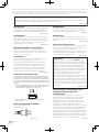
LINE VOLTAGE SELECTOR SWITCH
The line voltage selector switch is located on the side panel of this
mixier.The factory setting for the voltage selector is 220-240V. Check
that it is set properly before plugging the power cord into the outlet.
If the voltage is not properly set or if you move to an area where the
voltage requirements differ, adjust the selector switch as follows:
Use a medium-sized (flat blade) screwdriver. Insert the tip of the
screwdriver into the groove of the selector switch and set it so that
the power voltage marking of your area points to the arrow.
110-120V 220-240V
VOLTAGE
SELECTOR
For Taiwan, please set to 110-120V before using.
CAUTION
The POWER switch on this unit will not completely
shut off all power from the AC outlet. Since the power
cord serves as the main disconnect device for the
unit, you will need to unplug it from the AC outlet to
shut down all power. Therefore, make sure the unit
has been installed so that the power cord can be
easily unplugged from the AC outlet in case of an
accident. To avoid fire hazard, the power cord should
also be unplugged from the AC outlet when left
unused for a long period of time (for example, when
on vacation).
D3-4-2-2-2a*_A1_En

4
En
Before you start
How to read this manual
Be sure to read both this leaflet and the Operating Instructions contained on the CD-ROM accompanying this product! Both documents include impor-
tant information that you must understand before using this product.
! In this manual, names of channels and buttons indicated on the product, names of menus in the software, etc., are indicated within square brack-
ets ([ ]). (e.g. [MASTER] channel, [ON/OFF], [File] menu)
What’s in the box
! Driver software/operating instructions CD-ROM
! USB cable
! Power cord(s)
! Read Before Use (Important)/Quick Start Guide (this document)
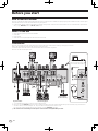
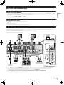
Connections
Be sure to turn off the power and unplug the power cord from the power outlet whenever making or changing connections.
Refer to the operating instructions for the component to be connected.
Connect the power cord after all the connections between devices have been completed.
Be sure to use the included power cord.
OFF
RETURN
L
1 GND
2 HOT
3 COLD
LR
R
L
R
L
R
L
R
CH 4CH 3
L
R
PHONO
CH 1
CD/LINE
L
R
PHONOCD/LINE
L
RR
LINECD/LINE
L
LINECD/LINE
SIGNAL GNDSIGNAL GND
MASTER1
BOOTH
REC OUTMASTER2
CH2
CONTROL
DIGITAL
MASTER OUT
CH 2
(MONO)
LR
(MONO)
SEND
POWER
AC IN
ON
CH3
L
R
L
R
To power outlet
Analog player Analog player
L
R
L
R
Pioneer DJ players
L
R
Power amplifier
(for booth monitor)
L
R
Power amplifier
12
1 2 534
a 9 8 7 6
MASTER
0
LEVEL
CUE
PHONES
MIC
LEVEL
MI
CU
SB
Microphone
Headphones
Computer
Be sure to connect using
the included USB cable.
b
c
d
! To use the fader start function, connect a control cable (page 8).
1 Be sure to use the [MASTER1] terminals only for a balanced output. Connection with an unbalanced input (such as RCA) using an XLR to RCA
converter cable (or converter adapter), etc., may lower the sound quality and/or result in noise.
For connection with an unbalanced input (such as RCA), use the [MASTER2] terminals.
2 Be careful not to accidentally insert the power cord of another unit to [MASTER1] terminal.

5
En
English
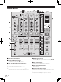
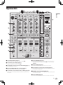
1 POWER button (page 7)
Turns this unit’s power on and off.
2 PHONO terminals
Connect to a phono level (MM cartridge) output device. Do not input
line level signals.
To connect a device to the [PHONO] terminals, remove the short-
circuit pin plug inserted in the terminals.
Insert this short-circuit pin plug into the [PHONO] terminals when
nothing is connected to them to cut external noise.
3 CD/LINE terminals
Connect to a DJ player or a line level output component.
4 SIGNAL GND terminal
Connects an analog player’s ground wire here. This helps reduce
noise when the analog player is connected.
5 LINE terminals
Connect to a cassette deck or a line level output component.
6 CONTROL terminal
This is a Ø 3.5 mm mini phone jack type DJ player control terminal.
If you connect a Pioneer DJ player using a control cable (supplied
with a DJ player), you can start playback of control other operations
of the DJ player with the fader of this unit.
7 BOOTH terminals
These are output terminals for a booth monitor.
8 MASTER2 terminals
Connect to a power amplifier, etc.
9 MASTER1 terminals
Connect to a power amplifier, etc.
Be sure to use these as balanced outputs. Be careful not to acci-
dentally insert the power cord of another unit.
a AC IN
Connects to a power outlet using the included power cord. Wait until
all connections between the equipment are completed before con-
necting the power cord.
Be sure to use the included power cord.
b MIC terminal (page 8)
Connects a microphone here.
c USB terminal
Connect the computer.
d PHONES terminal (page 7)
Connect headphones here.
WARNING
The short-circuit pin plugs out of the reach of children and infants. If
accidentally swallowed, contact a doctor immediately.

6
En
Operation
MIC
LEVEL
EQ
0
POWER
MIC USB
AUTO
/ TAP
BOOST
CH SELECT
PARAMETER
1 2 3 4
MIC
A B
MST
TIME
MAX
LEVEL /DEPTH
ON / OFF
MIN
BEAT EFFECTS
BEAT
TAP
ON/OFF
ROBOT
SPIRAL
PHASER
ROLL
SLIP ROLL
REV ROLL
FLANGER
TRANS
FILTER
SND/ RTN
VINYL BRAKE
REVERB
ECHO
DELAY
HI
LOW
12 12
12 12
ON
TALK
OVER
OFF
CH-2 CH-3
FADER START
MIDI
HEAD PHONES
STEREOMONO SPLIT
MASTER
0
MIXING
LEVEL
CUE
PHONES
BA THRU
10
9
8
7
6
5
4
3
2
1
0
BA THRU
10
9
8
7
6
5
4
3
2
1
0
OVER
10
7
4
2
1
-
1
-
2
-
3
-
5
-
7
-
10
-
15
-
24
RL
dB
0
BA THRU
10
9
8
7
6
5
4
3
2
1
0
CD/LINE
PHONO
USB
7/8
EQ /
TRIM
9
HI
6
-
26
/
MID
6
-
26
/
LOW
6
-
26
/
ISO
OVER
10
7
4
2
1
-
1
-
2
-
3
-
5
-
7
-
10
-
15
-
24
dB
0
BA THRU
STEREO
EQ
MONO
BA
ISOLATOR
WAKE UP
LEVEL
0
BALANCE
RL
MASTER
BOOTH MONITOR
EQ CURVE
CH FADER
CROSS FADER
0
START
/STOP
AUTO
TAP
BPM
%
ms
1
2
3
4
MIC
CF.A
CF.B
MASTER
CROSS FADER ASSIGN
HEADPHONE CUE
CUE
SOUND COLOR FX
LOW HI
CD/LINE
LINE
USB
5/6
EQ /
TRIM
9
HI
6
-
26
/
MID
6
-
26
/
LOW
6
-
26
/
ISO
OVER
10
7
4
2
1
-
1
-
2
-
3
-
5
-
7
-
10
-
15
-
24
dB
0
CD/LINE
LINE
USB
3/4
EQ /
TRIM
9
HI
6
-
26
/
MID
6
-
26
/
LOW
6
-
26
/
ISO
OVER
10
7
4
2
1
-
1
-
2
-
3
-
5
-
7
-
10
-
15
-
24
dB
0
CD/LINE
PHONO
USB
1/2
EQ /
TRIM
9
HI
6
-
26
/
MID
6
-
26
/
LOW
6
-
26
/
ISO
OVER
10
7
4
2
1
-
1
-
2
-
3
-
5
-
7
-
10
-
15
-
24
dB
0
SETUP
CUE
NOISE
JET
CRUSH
FILTER
1
3
5
6
7
4
2
n
f
g
c
i
j
k
l
m
d
a
b
9
c
e
8
h
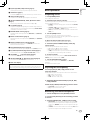
1 MIC LEVEL control (page 8)
Adjusts the sound level output from the [MIC] channel.
2 EQ (HI, LOW) controls (page 8)
Adjusts the sound quality of the [MIC] channel.
3 OFF, ON, TALK OVER selector switch (page 8)
Turns the microphone on/off.
4 FADER START (CH-2, CH-3) buttons (page 8)
These turn the fader start function on/off.
5 MONO SPLIT, STEREO selector switch (page 7)
Switches how the monitor sound output from the headphones is
distributed.
6 MIXING control (page 7)
This adjusts the monitor volume balance of the sound of channels for
which the [CUE] button is pressed and the sound of the [MASTER]
channel.
7 LEVEL control (page 7)
Adjusts the sound level output from the headphones.
8 Input selector switches (page 7)
Selects the input source of each channel from the components con-
nected to this unit.
9 Channel Level Indicator (page 7)
Displays the sound level of the respective channels before passing
through the channel faders.
a TRIM control (page 7)
Adjusts the level of audio signals input in each channel.

7
En
English
b EQ/ISO (HI, MID, LOW) controls (page 7)
These adjust the sound quality of the respective channels.
c CUE button (page 7)
Presses the [CUE] button(s) for the channel(s) you want to monitor.
d Channel Fader (page 7)
Adjusts the level of audio signals output in each channel.
e CROSS FADER ASSIGN (A, THRU, B) selector switch
(page 7)
Sets the output destination of each channel to [A] or [B].
f Crossfader (page 7)
Outputs audio signals assigned by the crossfader assign switch cor-
responding to the curve characteristics selected by [CROSS FADER]
(Crossfader Curve Selector Switch).
g MASTER LEVEL control (page 7)
Adjusts the audio level output from the [MASTER1] and [MASTER2]
terminals.
h Master Level Indicator (page 7)
Displays the audio level output from the [MASTER1] and [MASTER2]
terminals.
i MONO, STEREO selector switch (page 8)
Switches the sound output from the [MASTER1] terminals, etc.,
between monaural and stereo.
j BOOTH MONITOR control (page 8)
Adjusts the level of audio signals output from the [BOOTH] terminal.
k EQ CURVE (ISOLATOR, EQ) selector switch (page 7)
Switches the function of the [EQ/ISO (HI, MID, LOW)] controls.
l CH FADER ( , ) selector switch (page 8)
Switches the channel fader’s curve characteristics.
m CROSS FADER ( , , ) selector switch (page 8)
This switches the crossfader curve characteristics.
n Main unit display
Do not pull on the channel fader and crossfader knobs with excessive
force. The knobs have a structure by which they cannot be pulled off
easily. Pulling the knobs strongly may result in damaging the unit.
Basic Operation
Outputting sound
1 Press [POWER] button.
Turn on the power of this unit.
2 Switch the input selector switches.
Selects the input sources for the different channels from among the
devices connected to this unit.
— [PHONO]: Selects the analog player connected to the [PHONO]
terminals.
— [CD/LINE], [LINE]: Selects the DJ player or cassette deck con-
nected to the [CD/LINE] or [LINE] terminals.
— [USB */*]: Selects the sound of the computer connected to the
[USB] port.
3 Turn the [TRIM] control.
Adjusts the level of audio signals input in each channel.
The corresponding channel level indicator lights when audio signals are
being properly input to that channel.
4 Move the channel fader away from you.
Adjusts the level of audio signals output in each channel.
5 Switch the [CROSS FADER ASSIGN (A, THRU, B)]
selector switch.
Switches the output destination of each channel.
— [A]: Assigns to [A] (left) of the crossfader.
— [B]: Assigns to [B] (right) of the crossfader.
— [THRU]: Selects this when you do not want to use the crossfader.
(The signals do not pass through the crossfader.)
6 Set the crossfader.
This operation is not necessary when the [CROSS FADER ASSIGN (A,
THRU, B)] selector switch is set to [THRU].
7 Turn the [MASTER LEVEL] control.
Audio signals are output from the [MASTER1] and [MASTER2]
terminals.
The master level indicator lights.
Adjusting the sound quality
Turn the [EQ/ISO (HI, MID, LOW)] controls for the
respective channels.
The adjustable ranges for the respective controls are as shown below.
! HI: –26 dB to +6 dB (13 kHz)
! MID: –26 dB to +6 dB (1 kHz)
! LOW: –26 dB to +6 dB (70 Hz)
Switching the function of the [EQ/ISO (HI, MID,
LOW)] controls
Switch the [EQ CURVE (ISOLATOR, EQ)] selector switch.
— [ISOLATOR]: Functions as an isolator.
— [EQ]: The equalizer function is set.
Monitoring sound with headphones
1 Connect headphones to the [PHONES] terminal.
2 Press the [CUE] button(s) for the channel(s) you want
to monitor.
3 Switch the [MONO SPLIT, STEREO] selector switch.
— [MONO SPLIT]: The sound of the channels for which the [CUE]
button is pressed is output from the headphones output’s left
channel, the [MASTER] channel sound is output from the right
channel.
— [STEREO]: The sound of the channels for which the [CUE] button
is pressed is output from the headphones in stereo.

8
En
4 Turn the [MIXING] control.
This adjusts the monitor volume balance of the sound of channels for
which the [CUE] button is pressed and the sound of the [MASTER]
channel.
5 Turn the [LEVEL] control for [HEADPHONES].
The sound of the channels for which the [CUE] button is pressed is
output from the headphones.
! When the [CUE] button is pressed again, monitoring is canceled.
Switching the fader curve
Select the channel fader curve characteristics
Switch the [CH FADER (
, )] selector switch.
— [ ]: The curve rises suddenly at the back side.
— [ ]: The curve rises gradually (the sound gradually increases as
the channel fader is moved away from the front side).
Select the crossfader curve characteristics
Switch the [CROSS FADER (
, , )] selector switch.
— [ ]: Makes a sharply increasing curve (if the crossfader is
moved away from the [A] side, audio signals are immediately
output from the [B] side).
— [ ]: Makes a curve shaped between the two curves above and
below.
— [ ]: Makes a gradually increasing curve (if the crossfader is
moved away from the [A] side, the sound on the [B] side gradu-
ally increases, while the sound on the [A] gradually decreases).
Starting playback on a DJ player using
the fader (fader start)
If you connect a Pioneer DJ player using a control cable (supplied with
a DJ player), you can start playback of control other operations of the DJ
player with the fader of this unit.
Connect this unit and Pioneer DJ player beforehand. For instructions on
connections, see Connections on page 4.
Start playback using the channel fader
1 Set the [CROSS FADER ASSIGN (A, THRU, B)] selector
switch to [THRU].
2 Press one of the [FADER START (CH-2, CH-3)] buttons.
Select the channel to be started with the fader start function.
3 Set the channel fader to the nearest position towards
you.
4 Set the cue on the DJ player.
The DJ player pauses playback at the cue point.
5 Move the channel fader away from you.
Playback starts on the DJ player.
! If you set the channel fader back to the original position, the player
instantaneously returns to the cue point already set and pauses
playback (back cue).
Start playback using the crossfader
1 Set the [CROSS FADER ASSIGN (A, THRU, B)] selector
switch to [A] or [B].
2 Press one of the [FADER START (CH-2, CH-3)] buttons.
Select the channel to be started with the fader start function.
3 Set the crossfader.
Set to the edge opposite the side on which the channel you want to use
with the fader start function is set.
4 Set the cue on the DJ player.
The DJ player pauses playback at the cue point.
5 Set the crossfader.
Playback starts on the DJ player.
! If you set the crossfader back to the original position, the player
instantaneously returns to the cue point already set and pauses
playback (back cue).
Using a microphone
1 Connect the microphone to the [MIC] jack.
2 Set the [OFF, ON, TALK OVER] selector switch to [ON]
or [TALK OVER].
— [ON]: The indicator lights.
— [TALK OVER]: The indicator flashes.
! When set to [TALK OVER], the sound of channels other than the
[MIC] channel is attenuated by 18 dB (default) when a sound of –10
dB or greater is input to the microphone.
! The audio attenuation level for the [TALK OVER] mode can be
changed at the [USER SETUP] screen. For instructions on changing
the level, see this product’s operating instructions.
! The talk over mode can be switched between the normal mode and
the advanced mode. For instructions on changing the mode, see this
product’s operating instructions.
3 Turn the [MIC LEVEL] control.
Adjust the level of the sound output from the [MIC] channel.
! Pay attention that rotating to the extreme right position outputs a
very loud sound.
4 Input audio signals to the microphone.
Adjusting the sound quality
Turn the [MIC] channels’ [EQ (HI, LOW)] controls.
The adjustable ranges for the respective controls are as shown below.
! HI: –12 dB to +12 dB (10 kHz)
! LOW: –12 dB to +12 dB (100 Hz)
Switching between monaural and stereo
audio
This switches the sound output from the [MASTER1], [MASTER2],
[BOOTH], [REC OUT], [PHONES], [DIGITAL MASTER OUT] and [USB]
terminals between monaural and stereo.
! To adjust the sound output from the [USB] terminals, select [REC
OUT] at [Mixer Audio Output] in the setting utility.
Switch the [MONO, STEREO] selector switch.
— [MONO]: Outputs monaural audio.
— [STEREO]: Outputs stereo audio.
Adjusting the L/R balance of audio
The left/right balance of the sound output from the [MASTER1],
[MASTER2], [BOOTH], [REC OUT], [PHONES], [DIGITAL MASTER OUT]
and [USB] terminals can be adjusted.
! To adjust the sound output from the [USB] terminals, select [REC
OUT] at [Mixer Audio Output] in the setting utility.
1 Set the [MONO, STEREO] selector switch to [STEREO].
2 Turn the [BALANCE] control.
The sound’s left/right balance changes according to the direction in
which the [BALANCE] control is turned and its position.
! Rotating to the rightmost position outputs only the right sound of
stereo audio. Rotating to the leftmost position outputs only the left
sound of stereo audio.
Audio is output from the [BOOTH]
terminal
Turn the [BOOTH MONITOR] control.
Adjusts the level of audio signals output from the [BOOTH] terminal.

9
En
English
Additional information
About trademarks and registered
trademarks
! Pioneer is a registered trademark of PIONEER CORPORATION.
! Microsoft, Windows and Windows Vista are either registered trade-
marks or trademarks of Microsoft Corporation in the United States
and/or other countries.
! Apple, Macintosh and Mac OS are trademarks of Apple Inc., regis-
tered in the U.S. and other countries.
! ASIO is a trademark of Steinberg Media Technologies GmbH.
! The names of companies and products mentioned herein are the
trademarks of their respective owners.
Specifications
General
Power requirements ........AC 110 V to 120 V or 220 V to 240 V, 50 Hz/60 Hz
Power consumption ............................................................................... 32 W
Power consumption (standby) ........................................................... 0.45 W
Main unit weight ...................................................................................7.6 kg
Max. external dimensions ........320 mm (W) × 108 mm (H) × 376 mm (D)
Tolerable operating temperature ........................................+5 °C to +35 °C
Tolerable operating humidity ...................... 5 % to 85 % (no condensation)
Audio Section
Sampling rate ......................................................................................96 kHz
MASTER D/A converter .......................................................................24 bits
Other A/D and D/A converters ............................................................24 bits
Frequency characteristic
CD/LINE ........................................................................... 20 Hz to 20 kHz
S/N ratio (rated output, A-WEIGHTED)
PHONO............................................................................................ 92 dB
CD/LINE ......................................................................................... 106 dB
MIC .................................................................................................. 84 dB
Total harmonic distortion (20 kHzBW)
CD/LINE — MASTER1.................................................................0.004 %
Standard input level / Input impedance
PHONO.............................................................................–52 dBu/47 kW
CD/LINE ............................................................................ –12 dBu/47 kW
MIC .................................................................................. –52 dBu/8.5 kW
RETURN ............................................................................–12 dBu/49 kW
Standard output level / Load impedance / Output impedance
MASTER1 ................................................ +6 dBu/10 kW/360 W or lower
MASTER2 ................................................ +2 dBu/10 kW/390 W or lower
REC OUT .....................................................–8 dBu/10 kW/22 W or lower
BOOTH .................................................... +2 dBu/10 kW/390 W or lower
SEND .......................................................–12 dBu/10 kW/390 W or lower
PHONES ................................................... +8.5 dBu/32 W/10 W or lower
Rated output level / Load impedance
MASTER1 ........................................................................ +24 dBu/10 kW
MASTER2 ........................................................................ +20 dBu/10 kW
Crosstalk
LINE ................................................................................................. 82 dB
Channel equalizer characteristic
HI .....................................................................–26 dB to +6 dB (13 kHz)
MID .................................................................... –26 dB to +6 dB (1 kHz)
LOW ..................................................................–26 dB to +6 dB (70 Hz)
Microphone equalizer characteristic
HI ...................................................................–12 dB to +12 dB (10 kHz)
LOW ..............................................................–12 dB to +12 dB (100 Hz)
Input / Output terminals
PHONO input terminal
RCA pin jack ....................................................................................2 sets
CD/LINE input terminal
RCA pin jacks ..................................................................................4 sets
LINE input terminal
RCA pin jack ....................................................................................2 sets
MIC input terminal
XLR connector/phone jack (Ø 6.3 mm) ...........................................1 set
RETURN Input terminals
Phone jack (Ø 6.3 mm) ..................................................................... 1 set
MASTER output terminal
XLR connector...................................................................................1 set
RCA pin jacks ....................................................................................1 set
BOOTH output terminal
RCA pin jacks ....................................................................................1 set
REC OUT output terminal
RCA pin jacks ....................................................................................1 set
SEND output terminal
Phone jack (Ø 6.3 mm) ..................................................................... 1 set
DIGITAL MASTER OUT coaxial output terminal
RCA pin jacks ....................................................................................1 set
PHONES output terminal
Stereo phone jack (Ø 6.3 mm) .........................................................1 set
USB terminal
B type ................................................................................................. 1 set
CONTROL terminal
Mini phone jack (Ø 3.5 mm) ...........................................................2 sets
— The specifications and design of this product are subject to
change without notice.
— Be sure to use the [MASTER1] terminals only for a balanced
output. Connection with an unbalanced input (such as RCA)
using an XLR to RCA converter cable (or converter adapter), etc.,
may lower the sound quality and/or result in noise.
For connection with an unbalanced input (such as RCA), use the
[MASTER2] terminals.
! © 2013 PIONEER CORPORATION. All rights reserved.

2
Es
Le damos las gracias por la adquisición de este producto Pioneer. Lea a fondo estas instrucciones de utilización para que aprenda a utilizar correctamente su
modelo. Después de haber terminado de leer estas instrucciones, guárdelas en un lugar seguro para, en caso de ser necesario, consultarlas en el futuro.
En algunos países o regiones, la forma de la clavija de alimentación y de la toma de corriente pueden ser algunas veces diferentes de la mostrada en
las ilustraciones explicativas. Sin embargo, el método de conexión y funcionamiento de la unidad es el mismo.
PRECAUCIÓN
PARA PREVENIR EL PELIGRO DE CHOQUE ELÉCTRICO
NO REMOVER LA TAPA NI LAS PARTES DENTRO NO
UTILIZADAS, LLAMAR UNA PERSONA CUALIFICADA.
D3-4-2-1-1_B1_Es
ADVERTENCIA
Este aparato no es impermeable. Para evitar el riesgo
de incendio y de descargas eléctricas, no ponga ningún
recipiente lleno de líquido (como pueda ser un vaso o
un florero) cerca del aparato ni lo exponga a goteo,
salpicaduras, lluvia o humedad.
D3-4-2-1-3_A1_Es
ADVERTENCIA
Para evitar el peligro de incendio, no ponga nada con
fuego encendido (como pueda ser una vela) encima del
aparato.
D3-4-2-1-7a_A1_Es
Entorno de funcionamiento
Temperatura y humedad del entorno de funcionamiento
+5 °C a +35 °C; menos del 85 % de humedad relativa
(rejillas de refrigeración no obstruidas)
No instale este aparato en un lugar mal ventilado, ni en
lugares expuestos a alta humedad o a la luz directa del
sol (o de otra luz artificial potente).
D3-4-2-1-7c*_A1_Es
PRECAUCIÓN
El interruptor de la alimentación POWER de este
aparato no corta por completo toda la alimentación
de la toma de corriente de CA. Puesto que el cable de
alimentación hace las funciones de dispositivo de
desconexión de la corriente para el aparato, para
desconectar toda la alimentación del aparato deberá
desenchufar el cable de la toma de corriente de CA.
Por lo tanto, asegúrese de instalar el aparato de
modo que el cable de alimentación pueda
desenchufarse con facilidad de la toma de corriente
de CA en caso de un accidente. Para evitar correr el
peligro de incendio, el cable de alimentación también
deberá desenchufarse de la toma de corriente de CA
cuando no se tenga la intención de utilizarlo durante
mucho tiempo seguido (por ejemplo, antes de irse de
vacaciones).
D3-4-2-2-2a*_A1_Es
ADVERTENCIA
Guarde las piezas pequeñas fuera del alcance de los
niños. Si las ingirieran accidentalmente, póngase de
inmediato en contacto con un médico.
D41-6-4_A1_Es
PRECAUCIONES CONCERNIENTES A LA
MANIPULACIÓN DEL CABLE DE
ALIMENTACIÓN
Tome el cable de alimentación por la clavija. No
extraiga la clavija tirando del cable. Nunca toque el
cable de alimentación cuando sus manos estén
mojadas, ya que esto podría causar cortocircuitos o
descargas eléctricas. No coloque la unidad, algún
mueble, etc., sobre el cable de alimentación.
Asegúrese de no hacer nudos en el cable ni de unirlo a
otros cables. Los cables de alimentación deberán ser
dispuestos de tal forma que la probabilidad de que
sean pisados sea mínima. Una cable de alimentación
dañado podrá causar incendios o descargas eléctricas.
Revise el cable de alimentación está dañado, solicite el
reemplazo del mismo al centro de servicio autorizado
PIONEER más cercano, o a su distribuidor.
S002*_A1_Es
Para uso exclusivo en Taiwán
Clavija Taiwanesa de dos
contactos planos
K056_A1_Es
AVISO
Este producto cumple con las normas de la FCC cuando se usan conectores y cables blindados para conectar la
unidad a otro equipo. Para impedir la interferencia electromagnética con aparatos eléctricos tales como radios y
televisiones, use conectores y cables blindados para hacer las conexiones.
D8-10-3a_A1_Es
SELECTOR DE TENSION DE LINEA
El selector de tension esta situado en el panel posterior de esta
consola de mezcla. El selector de tension sale de fabrica ajustado
para 220-240 V. Compruebe que este correctamente ajustado antes
de enchufar el cable de alimentacion a la toma de alimentacion. Si la
tension no esta correctamente ajustada, ajuste el selector del modo
siguiente:
Utilice un destornillador de tamano medio (cabeza plana). Inserte
la punta del destornillador en la ranura del selector y girelo de
modo que la flecha indique la tension de su zona.
110-120V 220-240V
VOLTAGE
SELECTOR
Para Taiwan, ajustelo para 110-120 V antes de ponerlo en
funcionamiento.
PRECAUCIÓN PARA LA VENTILACIÓN
Cuando instale este aparato, asegúrese de dejar
espacio en torno al mismo para la ventilación con el fin
de mejorar la disipación de calor (por lo menos 5 cm
detrás, y 3 cm en cada lado).
ADVERTENCIA
Las ranuras y aberturas de la caja del aparato sirven
para su ventilación para poder asegurar un
funcionamiento fiable del aparato y para protegerlo
contra sobrecalentamiento. Para evitar el peligro de
incendio, las aberturas nunca deberán taparse ni
cubrirse con nada (como por ejemplo, periódicos,
manteles, cortinas) ni ponerse en funcionamiento el
aparato sobre una alfombra gruesas o una cama.
D3-4-2-1-7b*_A1_Es

3
Es
Antes de comenzar
Cómo leer este manual
Asegúrese de leer este folleto y el manual de instrucciones contenido en el CD-ROM suministrado con este producto. Ambos documentos incluyen
información importante que usted deberá entender antes de usar este producto.
! En este manual, los nombres de canales y botones indicados en el producto, los nombres de menús del software, etc., se indican dentro de corche-
tes ([ ]). (p. ej.: Canal [MASTER], [ON/OFF], menú [File])
Contenido de la caja
! CD-ROM de software controlador/manual de instrucciones
! Cable USB
! Cable(s) de alimentación
! Léalo antes de usar (Importante)/Guía de inicio rápido (este manual)
Conexiones
Asegúrese de desconectar la alimentación y desenchufar el cable de alimentación de la toma de corriente siempre que haga o cambie conexiones.
Consulte el manual de instrucciones del componente que va a ser conectado.
Conecte el cable de alimentación después de terminar las conexiones entre los aparatos.
Asegúrese de usar el cable de alimentación incluido.
OFF
RETURN
L
1 GND
2 HOT
3 COLD
LR
R
L
R
L
R
L
R
CH 4CH 3
L
R
PHONO
CH 1
CD/LINE
L
R
PHONOCD/LINE
L
RR
LINECD/LINE
L
LINECD/LINE
SIGNAL GNDSIGNAL GND
MASTER1
BOOTH
REC OUTMASTER2
CH2
CONTROL
DIGITAL
MASTER OUT
CH 2
(MONO)
LR
(MONO)
SEND
POWER
AC IN
ON
CH3
L
R
L
R
A una toma
de corriente
Reproductor analógico Reproductor analógico
L
R
L
R
Reproductores DJ de Pioneer
L
R
Amplificador de potencia
(para monitor de cabina)
L
R
Amplificador de
potencia
12
1 2 534
a 9 8 7 6
MASTER
0
LEVEL
CUE
PHONES
MIC
LEVEL
MI
CU
SB
Micrófono
Auriculares
Ordenador
Asegúrese de conectar usando
el cable USB incluido.
b
c
d
! Para usar la función de inicio de fader, conecte un cable de control (página 7).
1 Asegúrese de usar los terminales [MASTER1] sólo para una salida equilibrada. La conexión con una entrada desequilibrada (tal como RCA)
usando un XLR a un cable de convertidor RCA (o adaptador de convertidor), etc., puede reducir la calidad del sonido y/o crear ruido.
Para la conexión con una entrada desequilibrada (tal como RCA), use los terminales [MASTER2].
2 Tenga cuidado para no conectar por error el cable de alimentación de otra unidad al terminal [MASTER1].
Español

4
Es
1 Botón POWER (página 6)
Conecta y desconecta la alimentación de esta unidad.
2 Terminales PHONO
Conecte a un aparato con salida fonográfica (cápsula MM). No
introduzca señales de nivel de línea.
Para conectar un aparato a los terminales [PHONO], retire la clavija
de cortocircuito insertada en los terminales.
Inserte esta clavija de cortocircuito en los terminales [PHONO]
cuando no haya nada conectado a ellos para cortar el ruido externo.
3 Terminales CD/LINE
Conecte a un reproductor DJ o a un componente de salida de nivel
de línea.
4 Terminal SIGNAL GND
Conecta aquí el cable de tierra de un reproductor analógico.
Esto ayuda a reducir el ruido cuando se conecta un reproductor
analógico.
5 Terminales LINE
Conecte a una platina de casete o a un componente de salida de
nivel de línea.
6 Terminal CONTROL
Éste es un terminal de control de reproductor DJ del tipo de minico-
nector telefónico de Ø 3,5 mm.
Si conecta un reproductor DJ de Pioneer usando un cable de control
(suministrado con el reproductor DJ), usted puede iniciar la repro-
ducción o el control de otra operaciones del reproductor DJ con el
fader de esta unidad.
7 Terminales BOOTH
Éstos son terminales de salida para un monitor de cabina.
8 Terminales MASTER2
Conecte a un amplificador de potencia, etc.
9 Terminales MASTER1
Conecte a un amplificador de potencia, etc.
Asegúrese de usar éstas como salidas balanceadas. Tenga cui-
dado para no conectar por error el cable de alimentación de
otra unidad.
a AC IN
Conecta a una toma de corriente con el cable de alimentación
incluido. Espere hasta que todas las conexiones entre el equipo
estén terminadas antes de conectar el cable de alimentación.
Asegúrese de usar el cable de alimentación incluido.
b Terminal MIC (página 7)
Conecta un micrófono aquí.
c Terminal USB
Conecte el ordenador.
d Terminal PHONES (página 6)
Conecte aquí los auriculares.
ADVERTENCIA
Las clavijas de cortocircuito deberán guardarse fuera del alcance
de los niños y los bebés. Si alguien traga una de ellas por accidente,
póngase en contacto inmediatamente con un médico.

5
Es
Español
Operación
MIC
LEVEL
EQ
0
POWER
MIC USB
AUTO
/ TAP
BOOST
CH SELECT
PARAMETER
1 2 3 4
MIC
A B
MST
TIME
MAX
LEVEL /DEPTH
ON / OFF
MIN
BEAT EFFECTS
BEAT
TAP
ON/OFF
ROBOT
SPIRAL
PHASER
ROLL
SLIP ROLL
REV ROLL
FLANGER
TRANS
FILTER
SND/ RTN
VINYL BRAKE
REVERB
ECHO
DELAY
HI
LOW
12 12
12 12
ON
TALK
OVER
OFF
CH-2 CH-3
FADER START
MIDI
HEAD PHONES
STEREOMONO SPLIT
MASTER
0
MIXING
LEVEL
CUE
PHONES
BA THRU
10
9
8
7
6
5
4
3
2
1
0
BA THRU
10
9
8
7
6
5
4
3
2
1
0
OVER
10
7
4
2
1
-
1
-
2
-
3
-
5
-
7
-
10
-
15
-
24
RL
dB
0
BA THRU
10
9
8
7
6
5
4
3
2
1
0
CD/LINE
PHONO
USB
7/8
EQ /
TRIM
9
HI
6
-
26
/
MID
6
-
26
/
LOW
6
-
26
/
ISO
OVER
10
7
4
2
1
-
1
-
2
-
3
-
5
-
7
-
10
-
15
-
24
dB
0
BA THRU
STEREO
EQ
MONO
BA
ISOLATOR
WAKE UP
LEVEL
0
BALANCE
RL
MASTER
BOOTH MONITOR
EQ CURVE
CH FADER
CROSS FADER
0
START
/STOP
AUTO
TAP
BPM
%
ms
1
2
3
4
MIC
CF.A
CF.B
MASTER
CROSS FADER ASSIGN
HEADPHONE CUE
CUE
SOUND COLOR FX
LOW HI
CD/LINE
LINE
USB
5/6
EQ /
TRIM
9
HI
6
-
26
/
MID
6
-
26
/
LOW
6
-
26
/
ISO
OVER
10
7
4
2
1
-
1
-
2
-
3
-
5
-
7
-
10
-
15
-
24
dB
0
CD/LINE
LINE
USB
3/4
EQ /
TRIM
9
HI
6
-
26
/
MID
6
-
26
/
LOW
6
-
26
/
ISO
OVER
10
7
4
2
1
-
1
-
2
-
3
-
5
-
7
-
10
-
15
-
24
dB
0
CD/LINE
PHONO
USB
1/2
EQ /
TRIM
9
HI
6
-
26
/
MID
6
-
26
/
LOW
6
-
26
/
ISO
OVER
10
7
4
2
1
-
1
-
2
-
3
-
5
-
7
-
10
-
15
-
24
dB
0
SETUP
CUE
NOISE
JET
CRUSH
FILTER
1
3
5
6
7
4
2
n
f
g
c
i
j
k
l
m
d
a
b
9
c
e
8
h
1 Control MIC LEVEL (página 7)
Ajusta la salida del nivel de sonido desde el canal [MIC].
2 Controles EQ (HI, LOW) (página 7)
Ajusta la calidad del sonido del canal [MIC].
3 Conmutador selector OFF, ON, TALK OVER (página 7)
Enciende/apaga el micrófono.
4 Botones FADER START (CH-2, CH-3) (página 7)
Éstos activan/desactivan la función de inicio del fader.
5 Conmutador selector MONO SPLIT, STEREO (página 6)
Cambia cómo se distribuye la salida de sonido de monitoreo de los
auriculares.
6 Control MIXING (página 6)
Éste ajusta el balance del volumen de monitoreo del sonido de los
canales para los que se pulsa el botón [CUE] y el sonido del canal
[MASTER].
7 Control LEVEL (página 6)
Ajusta la salida del nivel de sonido desde los auriculares.
8 Conmutadores selectores de entrada (página 6)
Selecciona la fuente de entrada de cada canal desde los componen-
tes conectados a esta unidad.
9 Indicador de nivel de canal (página 6)
Visualiza el nivel del sonido de los diferentes canales antes de pasar
por los fader de canales.
a Control TRIM (página 6)
Ajusta el nivel de las señales de audio introducidas en cada canal.

6
Es
b Controles EQ/ISO (HI, MID, LOW) (página 6)
Éstos ajustan la calidad del sonido de diferentes canales.
c Botón CUE (página 6)
Pulsa el botón, o botones, [CUE] del canal, o canales, que quiera
monitorear.
d Fader de canal (página 6)
Ajusta el nivel de las señales de audio que salen en cada canal.
e Conmutador selector CROSS FADER ASSIGN (A, THRU, B)
(página 6)
Establezca el destino de salida de cada canal en [A] o [B].
f Crossfader (página 6)
Envía señales de audio asignadas por el conmutador de asignación
de crossfader correspondiente a las características de curva selec-
cionadas por [CROSS FADER] (conmutador selector de curva de
crossfader).
g Control MASTER LEVEL (página 6)
Ajusta la salida de nivel de audio de los terminales [MASTER1] y
[MASTER2].
h Indicador de nivel maestro (página 6)
Visualiza la salida de nivel de audio de los terminales [MASTER1] y
[MASTER2].
i Conmutador selector MONO, STEREO (página 7)
Cambia la salida de sonido desde los terminales [MASTER1], etc.
entre mono y estéreo.
j Control BOOTH MONITOR (página 7)
Ajusta el nivel de las señales de audio que salen por el terminal
[BOOTH].
k Conmutador selector EQ CURVE (ISOLATOR, EQ)
(página 6)
Cambia la función de los controles [EQ/ISO (HI, MID, LOW)].
l Conmutador selector CH FADER ( , ) (página 7)
Cambia las características de la curva del fader de canales.
m Conmutador selector CROSS FADER ( , , )
(página 7)
Cambia las características de curva de crossfader.
n Pantalla de la unidad principal
No tire del fader de canales ni de los controles crossfader con una
fuerza excesiva. Los controles tienen una estructura que no permite
extraerlos fácilmente. Tirar con fuerza de los controles podría dañar la
unidad.
Funcionamiento básico
Salida de sonido
1 Pulse el botón [POWER].
Conecte la alimentación de esta unidad.
2 Cambia los conmutadores selectores de entrada.
Selecciona las fuentes de entrada para los canales diferentes de entre
los aparatos conectados a esta unidad.
— [PHONO]: Selecciona el reproductor analógico conectado a los
terminales [PHONO].
— [CD/LINE], [LINE]: Selecciona el reproductor DJ o la platina de
casete conectado a los terminales [CD/LINE] o [LINE].
— [USB */*]: Selecciona el sonido del ordenador conectado al
puerto [USB].
3 Gire el control [TRIM].
Ajusta el nivel de las señales de audio introducidas en cada canal.
El indicador de nivel de canal correspondiente se enciende cuando las
señales de audio están entrando correctamente en ese canal.
4 Mueva el fader de canal alejándolo de usted.
Ajusta el nivel de las señales de audio que salen en cada canal.
5 Cambie el conmutador selector [CROSS FADER ASSIGN
(A, THRU, B)].
Cambia el destino de salida de cada canal.
— [A]: Asigna a [A] (izquierda) del crossfader.
— [B]: Asigna a [B] (derecha) del crossfader.
— [THRU]: Selecciona esto cuando no quiera usar el crossfader.
(Las señales no pasan a través del crossfader.)
6 Ajuste el crossfader.
Esta operación no es necesaria cuando el conmutador selector
[CROSS FADER ASSIGN (A, THRU, B)] se pone en [THRU].
7 Gire el control [MASTER LEVEL].
Las señales de audio salen por los terminales [MASTER1] y [MASTER2].
El indicador de nivel maestro se enciende.
Ajuste de la calidad del sonido
Gire los controles [EQ/ISO (HI, MID, LOW)] de los
diferentes canales.
Las gamas ajustables de los controles respectivos se muestran abajo.
! HI: –26 dB a +6 dB (13 kHz)
! MID: –26 dB a +6 dB (1 kHz)
! LOW: –26 dB a +6 dB (70 Hz)
Cambio de la función de los controles [EQ/ISO
(HI, MID, LOW)]
Cambie el conmutador selector [EQ CURVE (ISOLATOR,
EQ)].
— [ISOLATOR]: Funciona como un aislador.
— [EQ]: La función de ecualizador se establece.
Monitoreo de sonido con auriculares
1 Conecte los auriculares al terminal [PHONES].
2 Pulse el botón, o botones, [CUE] del canal, o canales,
que quiera monitorear.
3 Cambie el conmutador selector [MONO SPLIT, STEREO].
— [MONO SPLIT]: El sonido de los canales para los que se pulsa el
botón [CUE] sale por el canal izquierdo de la salida de los auri-
culares, mientras que el sonido del canal [MASTER] sale por el
canal derecho.
— [STEREO]: El sonido de los canales para los que se pulsa el botón
[CUE] sale por los auriculares en estéreo.

7
Es
Español
4 Gire el control [MIXING].
Éste ajusta el balance del volumen de monitoreo del sonido de los cana-
les para los que se pulsa el botón [CUE] y el sonido del canal [MASTER].
5 Gire el control [LEVEL] para [HEADPHONES].
El sonido de los canales para los que se pulsa el botón [CUE] sale por los
auriculares.
! Cuando se pulsa de nuevo el botón [CUE], el monitoreo se cancela.
Cambio de la curva de fader
Seleccione las características de la curva de fader
de canales
Cambie el conmutador selector [CH FADER (
, )].
— [ ]: La curva sube bruscamente en el lado posterior.
— [ ]: La curva sube gradualmente (el sonido aumenta gradual-
mente al alejar el fader de canal del lado delantero).
Seleccione las características de curva de
crossfader
Cambie el conmutador selector [CROSS FADER (
, , )].
— [ ]: Hace una curva que aumenta bruscamente (si el crossfa-
der se separa del lado [A] salen inmediatamente señales de
audio desde el lado [B]).
— [ ]: Hace una curva que está a medias de las dos curvas de
arriba y abajo.
— [ ]: Hace una curva que aumenta gradualmente (si el crossfa-
der se separa del lado [A], el sonido del lado [B] aumenta
gradualmente, mientras que el sonido del lado [A] se reduce
gradualmente).
Inicio de reproducción en un reproductor
DJ usando el fader (inicio de fader)
Si conecta un reproductor DJ de Pioneer usando un cable de control
(suministrado con el reproductor DJ), usted puede iniciar la reproduc-
ción o el control de otra operaciones del reproductor DJ con el fader de
esta unidad.
Conecte de antemano esta unidad y el reproductor DJ de Pioneer. Para
conocer instrucciones de conexión, vea Conexiones en la página 3.
Inicie la reproducción usando un fader de canales
1 Ponga el conmutador selector [CROSS FADER ASSIGN
(A, THRU, B)] en [THRU].
2 Pulse uno de los botones [FADER START (CH-2, CH-3)].
Seleccione el canal que va a ser iniciado con la función de inicio del fader.
3 Ponga el fader de canales en la posición más próxima
a usted.
4 Ajuste el cue del reproductor DJ.
El reproductor DJ hace una pausa en la reproducción en el punto cue.
5 Mueva el fader de canal alejándolo de usted.
La reproducción empieza en el reproductor DJ.
! Si vuelve a ajustar el fader de canal en la posición original, el repro-
ductor vuelve instantáneamente al punto cue ya establecido y hace
una pausa en la reproducción (vuelta a punto cue).
Inicie la reproducción usando el crossfader
1 Ponga el conmutador selector [CROSS FADER ASSIGN
(A, THRU, B)] en [A] o [B].
2 Pulse uno de los botones [FADER START (CH-2, CH-3)].
Seleccione el canal que va a ser iniciado con la función de inicio del
fader.
3 Ajuste el crossfader.
Póngalo en el borde opuesto al lado en el que está establecido el canal
que quiera usar con la función de inicio de fader.
4 Ajuste el cue del reproductor DJ.
El reproductor DJ hace una pausa en la reproducción en el punto cue.
5 Ajuste el crossfader.
La reproducción empieza en el reproductor DJ.
! Si vuelve a ajustar el crossfader en la posición original, el reproduc-
tor vuelve instantáneamente al punto cue ya establecido y hace una
pausa en la reproducción (vuelta a punto cue).
Uso de un micrófono
1 Conecte el micrófono al conector [MIC].
2 Ponga el conmutador selector [OFF, ON, TALK OVER]
en [ON] o [TALK OVER].
— [ON]: El indicador se enciende.
— [TALK OVER]: El indicador parpadea.
! Cuando se pone en [TALK OVER], el sonido que no es el del canal
[MIC] se atenúa 18 dB (predeterminado) cuando se introduce un
sonido de –10 dB o más por el micrófono.
! El nivel de atenuación de audio para el modo [TALK OVER] se puede
cambiar en la pantalla [USER SETUP]. Para conocer instrucciones de
cómo cambiar el nivel, vea el manual de instrucciones de este producto.
! El modo de talk over se puede cambiar entre el modo normal y el
modo avanzado. Para conocer instrucciones de cómo cambiar el
modo, vea el manual de instrucciones de este producto.
3 Gire el control [MIC LEVEL].
Ajusta el nivel de la salida de sonido desde el canal [MIC].
! Tenga en cuenta que girar hasta la posición del extremo derecho da
salida a un sonido muy alto.
4 Introduzca señales de audio en el micrófono.
Ajuste de la calidad del sonido
Gire los controles [EQ (HI, LOW)] de los canales [MIC].
Las gamas ajustables de los controles respectivos se muestran abajo.
! HI: –12 dB a +12 dB (10 kHz)
! LOW: –12 dB a +12 dB (100 Hz)
Cambio entre audio mono y estéreo
Esto cambia el sonido que sale por los terminales [MASTER1],
[MASTER2], [BOOTH], [REC OUT], [PHONES], [DIGITAL MASTER OUT]
y [USB] entre mono y estéreo.
! Para ajustar la salida de sonido de los terminales [USB], seleccione
[REC OUT] en [Mixer Audio Output] en la utilidad de ajuste.
Cambie el conmutador selector [MONO, STEREO].
— [MONO]: Envía audio mono.
— [STEREO]: Envía audio estéreo.
Ajuste de balance L/R de audio
El balance derecho/izquierdo de la salida de sonido por los terminales
[MASTER1], [MASTER2], [BOOTH], [REC OUT], [PHONES], [DIGITAL
MASTER OUT] y [USB] se puede ajustar.
! Para ajustar la salida de sonido de los terminales [USB], seleccione
[REC OUT] en [Mixer Audio Output] en la utilidad de ajuste.
1 Ponga el conmutador selector [MONO, STEREO] en
[STEREO].
2 Gire el control [BALANCE].
El balance derecho/izquierdo del sonido cambia según el sentido de giro
del control [BALANCE] y su posición.
! El giro a la posición del extremo derecho sólo envía sonido del canal
derecho de audio estéreo. El giro a la posición del extremo izquierdo
sólo envía sonido del canal izquierdo de audio estéreo.
Sale audio del terminal [BOOTH]
Gire el control [BOOTH MONITOR].
Ajusta el nivel de las señales de audio que salen por el terminal [BOOTH].

8
Es
Información adicional
Acerca de las marcas de fábrica y
marcas registradas
! Pioneer es una marca registrada de PIONEER CORPORATION.
! Microsoft, Windows y Windows Vista son marcas comerciales o mar-
cas comerciales registradas de Microsoft Corporation en los Estados
Unidos y/o en otros países.
! Apple, Macintosh y Mac OS son marcas comerciales de Apple Inc.,
registradas en los EE.UU. y en otros países.
! ASIO es una marca de fábrica de Steinberg Media Technologies
GmbH.
! Los nombres de compañías y productos mencionados aquí son
marcas de fábrica de sus respectivos propietarios.
Especificaciones
Generales
Requisitos de potencia ...... CA 110 V a 120 V, o 220 V a 240 V, 50 Hz/60 Hz
Consumo de energía.............................................................................. 32 W
Consumo de energía (modo de espera) ............................................ 0,45 W
Peso de la unidad principal ................................................................. 7,6 kg
Dimensiones máximas .......... 320 mm (An) × 108 mm (Al) × 376 mm (Pr)
Temperatura de funcionamiento tolerable .......................... +5 °C a +35 °C
Humedad de funcionamiento tolerable .....5 % a 85 % (sin condensación)
Sección de audio
Frecuencia de muestreo .....................................................................96 kHz
Convertidor D/A MASTER .................................................................... 24 bits
Otros convertidores A/D y D/A ............................................................ 24 bits
Características de frecuencia
CD/LINE ............................................................................ 20 Hz a 20 kHz
Relación señal/ruido (salida nominal, A-WEIGHTED)
PHONO............................................................................................ 92 dB
CD/LINE ......................................................................................... 106 dB
MIC .................................................................................................. 84 dB
Distorsión armónica total (20 kHzBW)
CD/LINE — MASTER1.................................................................0,004 %
Nivel de entrada / Impedancia de entrada estándar
PHONO.............................................................................–52 dBu/47 kW
CD/LINE ............................................................................ –12 dBu/47 kW
MIC .................................................................................. –52 dBu/8.5 kW
RETURN ............................................................................–12 dBu/49 kW
Nivel de salida / Impedancia de carga / Impedancia de salida estándar
MASTER1 ............................................... +6 dBu/10 kW/360 W o menos
MASTER2 ............................................... +2 dBu/10 kW/390 W o menos
REC OUT ....................................................–8 dBu/10 kW/22 W o menos
BOOTH ................................................... +2 dBu/10 kW/390 W o menos
SEND ......................................................–12 dBu/10 kW/390 W o menos
PHONES .................................................. +8,5 dBu/32 W/10 W o menos
Nivel de salida nominal / Impedancia de carga
MASTER1 ........................................................................ +24 dBu/10 kW
MASTER2 ........................................................................ +20 dBu/10 kW
Diafonía
LINE ................................................................................................. 82 dB
Características del ecualizador de canales
HI ......................................................................–26 dB a +6 dB (13 kHz)
MID .....................................................................–26 dB a +6 dB (1 kHz)
LOW ...................................................................–26 dB a +6 dB (70 Hz)
Características del ecualizador del micrófono
HI ....................................................................–12 dB a +12 dB (10 kHz)
LOW ...............................................................–12 dB a +12 dB (100 Hz)
Terminales entrada / salida
Terminal de entrada PHONO
Conector de contactos RCA ....................................................... 2 juegos
Terminal de entrada CD/LINE
Conectores de contactos RCA ...................................................4 juegos
Terminal de entrada LINE
Conector de contactos RCA ....................................................... 2 juegos
Terminal de entrada MIC
Conector XLR/Conector fonográfico (Ø 6,3 mm) ........................1 juego
Terminales de entrada RETURN
Conector fonográfico (Ø 6,3 mm) ................................................1 juego
Terminal de salida MASTER
Conector XLR ................................................................................1 juego
Conectores de contactos RCA .....................................................1 juego
Terminal de salida BOOTH
Conectores de contactos RCA .....................................................1 juego
Terminal de salida REC OUT
Conectores de contactos RCA .....................................................1 juego
Terminal de salida SEND
Conector fonográfico (Ø 6,3 mm) ................................................1 juego
Terminal de salida coaxial DIGITAL MASTER OUT
Conectores de contactos RCA .....................................................1 juego
Terminal de salida PHONES
Conector fonográfico estéreo (Ø 6,3 mm) ...................................1 juego
Terminal USB
Tipo B .............................................................................................1 juego
Terminal CONTROL
Miniconector fonográfico (Ø 3,5 mm) .......................................2 juegos
Consumo de energía para México
Modo normal
1
.........................................................................32 Wh/día
Modo de espera
2
................................................................ 10,35 Wh/día
1 Considerando 1 hora de uso al día
2 Considerando 23 horas en el modo de espera
— Las especificaciones y diseño de este producto están sujetos a
cambios sin previo aviso.
— Asegúrese de usar los terminales [MASTER1] sólo para una
salida equilibrada. La conexión con una entrada desequilibrada
(tal como RCA) usando un XLR a un cable de convertidor RCA
(o adaptador de convertidor), etc., puede reducir la calidad del
sonido y/o crear ruido.
Para la conexión con una entrada desequilibrada (tal como
RCA), use los terminales [MASTER2].
! © 2013 PIONEER CORPORATION. Todos los derechos reservados.


PIONEER CORPORATION
1-1, Shin-ogura, Saiwai-ku, Kawasaki-shi, Kanagawa 212-0031, Japan
PIONEER ELECTRONICS ASIACENTRE PTE. LTD.
253 Alexandra Road, #04-01, Singapore 159936 TEL: 65-6472-7555
PIONEER ELECTRONICS AUSTRALIA PTY. LT D.
5 Arco Lane, Heatherton, Victoria, 3202, Australia, TEL: (03) 9586-6300
PIONEER ELECTRONICS (THAILAND) CO., LTD.
17th Fl., KPN To wer, 719 Rama 9 Road, Bangkapi, Huaykwang, Bangkok 10310 TEL: 66-2-717-0777
PIONEER TECHNOLOGY (MALAYSIA) SDN. BHD
16th Floor, Menara Uni. Asia 1008 Jalan Sultan Ismail 50250 Kuala Lumpur TEL: 60-3-2697-2920
ӒᎣӌԥ४ϵѨ
ѯᢋѯіҀϲୣ࿆ӏ ĵıĸ ဵĹዃ
TEL: 886-(0)2-2657-3588
ӒᎣႬφȞॸ෬ȟԥ४ϵѨ
ॸ෬Οᓹߞؔᢋၿ ĺıĺġဵ Ķġዃ
TEL: 852-2848-6488
PIONEER GULF FZE
Lob 11-017, Jebel Ali Free Zone P. O. Box 61226, Jebel Ali Dubai TEL: 971-4-8815756
PIONEER ELECTRONICS DE MEXICO S.A. DE C.V.
Blvd.Manuel Avila Camacho 138 10 piso Col.Lomas de Chapultepec, Mexico, D.F. 11000 TEL: 55-9178-4270
PIONEER INTERNATIONAL LATIN AMERICA S.A.
Plaza Credicorp Bank, 14th Floor, Calle 50, No.120 Panama City 0816-01361 Republic of Panama TEL: 507-300-3900
K002_PSV_L
<DRH1216-A>Printed in
© 2013 PIONEER CORPORATION.
All rights reserved.
-
 1
1
-
 2
2
-
 3
3
-
 4
4
-
 5
5
-
 6
6
-
 7
7
-
 8
8
-
 9
9
-
 10
10
-
 11
11
-
 12
12
-
 13
13
-
 14
14
-
 15
15
-
 16
16
-
 17
17
-
 18
18
-
 19
19
-
 20
20


Pioneer DJM-750-K El manual del propietario
- Categoría
- Controladores de DJ
- Tipo
- El manual del propietario
- Este manual también es adecuado para
en otros idiomas
- English: Pioneer DJM-750-K Owner's manual
Artículos relacionados
-
Pioneer DJM-350-W Manual de usuario
-
-
Pioneer DJM-750MK2 Guía de inicio rápido
-
Pioneer DJM-2000nexus El manual del propietario
-
Pioneer DJM-2000 Manual de usuario
-
Pioneer DJM-5000 Manual de usuario
-
-
Pioneer DJM-250-W El manual del propietario
-
-
Pioneer DJ DJM-S3 Manual de usuario