
MANUAL DE INSTRUCCIONES
A-268ATM Versión 1.0 1/1
A-268ATM
A
TENCI
Ó
N:
⋅ La instalación debe ser realizada por personal técnico
cualificado.
⋅ Conectar en paralelo los altavoces a los terminales de
salida correspondientes del amplificador.
⋅ Asegurarse de que todos los altavoces tengan la
misma polaridad.
⋅ No cambiar la toma del transformador mientras el
altavoz está en funcionamiento.
⋅ No exponer el equipo a fuentes de calor, ni a la llama.
ALTAVOZ DE TECHO
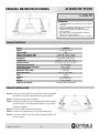
CARACTERÍSTICAS
Paso 1 – Recorte un circulo de Ø 230 mm en el techo. Utilice una plantilla
de cartulina o un cutter circular ajustado al tamaño requerido.
Paso 2 – Coloque el anclaje dentro del agujero.
Paso 3 – Afloje las palomillas y deslice los paneles móviles hasta que fijen
el anclaje al techo. Los paneles pueden doblarse si es necesario.
Apriete las palomillas.
Paso 4 – Conecte el cable de audio al transformador.
Paso 5 – Inserte los resortes del altavoz en las ranuras del anclaje.
Paso 6 – Presione el altavoz hacia arriba hasta que quede fijado en su
posición correcta.
Modelo A-268ATM
Altavoz 8” curvilíneo bicono
Potencia RMS 10 W
Selección de potencia 100 V 10 W, 5 W, 2’5 W y 1’25 W
Selección de potencia 70 V 5 W, 2’5 W, 1’25 W y 0’63 W
Impedancia
1 kΩ, 2 kΩ, 4 kΩ y 8 kΩ
Sensibilidad 92 dB SPL a 1 W, 1 m y 1 kHz
Presión acústica 102 dB SPL a 10 W, 1m y 1 kHz
Respuesta en frecuencia 70 ~ 20.000 Hz
Temperatura de funcionamiento -30º C ~ +60º C
Orificio a empotrar Ø 230 mm
Dispersion 1 kHz / 4kHz 100º / 45º
Dimensiones (mm) Ø 270 x 127 (fondo)
Peso 1,9 kg
Acabado Metálico
Color Blanco (RAL 9003)
Montaje Arco y muelles
Selección de potencia Terminales del transformador
GUÍA DE INSTALACIÓN

INSTRUCTION MANUAL
A-268ATM Version 1.0 1/1
A-268ATM
WARNING:
⋅ Installation by qualified personnel only.
⋅ Speakers must be wired in parallel and connected to
the correct line terminals of amplifier.
⋅ Ensure that all speakers have the same polarity with
respect to each other.
⋅ Do not select another tapings if the speaker is in use.
⋅ No naked flame sources, such as li
g
hted candles,
should be placed on the apparatus.
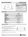
CEILING SPEAKER
SPECIFICATIONS
Step 1 – Cutout a Ø 230 mm circle on the ceiling. Use a cardboard cutout
template or a circular cutter set to the required cutout size.
Step 2 – Place the mounting bracket into the hole.
Step 3 – Loose the 2 wing bolts and slide the fixing plates until the bracket
is fixed to the ceiling. Fixing plates can be bent if necessary.
Tighten the 2 wing bolts.
Step 4 – Connect input cable to the transformer terminal.
Step 5 – Hang the speaker suspension springs on the hooks of mounting
bracket.
Step 6 – Push the speaker towards the hole till it reaches its correct position.
Model A-268ATM
Loudspeaker 8” curved bicone
Rated Power (RMS) 10 W
Power Taps 100 V 10 W, 5 W, 2’5 W & 1’25 W
Power Taps 70 V 5 W, 2’5 W, 1’25 W & 0’63 W
Impedance
1 kΩ, 2 kΩ, 4 kΩ & 8 kΩ
Sensitivity 92 dB SPL at 1 W, 1 m & 1 kHz
Sound Pressure 102 dB SPL at 10 W, 1 m & 1 kHz
Freq. Range 70 ~ 20.000 Hz
Operation temperature -30º C ~ +60º C
Cutout Size Ø 230 mm
Dispersion 1 kHz / 4 kHz 100º / 45º
Dimension (mm) Ø 270 x 127 (depth)
Weight 1,9 kg
Finish Metal
Colour White (RAL 9003)
Mounting Springs and bracket
Power selection Transformer taps
INSTALLATION GUIDE
-
 1
1
-
 2
2


en otros idiomas
- English: Optimus A-268ATM User manual
Artículos relacionados
-
Optimus A-267DTM Manual de usuario
-
-
-
-
-
-
-
-
-