
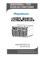
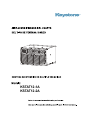
Model:KSTAT12-1A
WINDOW/WALL TYPE
ROOM AIR CONDITIONER
-
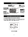
Before using your air conditioner, please read
this manual carefully and keep it for future reference.
KSTAT12-2A


Producto

1 866 646 4332
1 866 646 4332

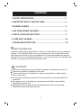
CONTENTS
Inside you will find many helpful hints on how to use and maintain your air conditioner
properly. Just a little preventive care on your part can save you a great deal of time
and money over the life of your air conditioner. You'll find many answers to common
problems in the chart of troubleshooting tips. If you review our chart of Troubleshooting
Tips first, you may not need to call for service at all.
Contact the authorized service technician for repair or maintenance of this unit.
Contact the installer for installation of this unit.
The air conditioner is not intended for use by young children or infirm persons
without supervision.
Young children should be supervised to ensure that they do not play with the air
conditioner.
If the power cord is to be replaced, replacement work shall be performed by
authorized personnel only.
Installation work must be performed in accordance with the national wiring
standards by authorized personnel only.
!
CAUTION
Read This Manual
1
1. SAFETY PRECAUTIONS..................................................................2
2. IMPORTANT SAFETY INSTRUCTIONS ..........................................4
3. NORMAL SOUNDS ...........................................................................5
4. AIR CONDITIONER FEATURES .......................................................5
5. INSTALLATION INSTRUCTIONS......................................................9
6. CARE AND CLEANING ....................................................................22
7. TROUBLESHOOTING TIPS...............................................................23

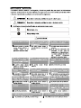
To prevent injury to the user or other people and property damage, the following instructions
must be followed. Incorrect operation due to ignoring of instructions may cause harm or
damage. The seriousness is classified by the following indications.
Safety Precautions
This symbol indicates the possibility of death or serious injury.
Meanings of symbols used in this manual are as shown below.
!
!
WARNING
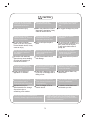
Always do this.
Never do this.
!
CAUTION
This symbol indicates the possibility of injury or damage to property.
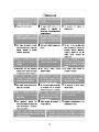
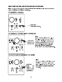
Plug in power plug
properly.
Do not modify power cord
length or share the outlet
with other appliances.
Always ensure effective
earthing.
Unplug the unit if strange
sounds, smell, or smoke
comes from it.
Keep firearms away.
Ventilate room before operating air
conditioner if there is a gas leakage from
another appliance.
Otherwise, it may cause electric
shock or fire due to heat
generation.
excess
It may cause electric shock or
fire due to heat generation.
Incorrect earthing may cause
electric shock.
It may cause fire and electric
shock.
It may cause fire.
It may cause explosion, fire and, burns.
It may cause electric shock or fire
due to heat generation.
It may cause electric shock.
It may cause failure of machine
or electric shock.
It may cause fire and electric
shock.
It may cause fire and electric
shock.
It may cause electric shock or fire.
If the power cord is damaged, it
must be replaced by the manufac-
turer or an authorised service
centre or a similarly qualified per-
son in order to avoid a hazard.
This could damage your health.
Incorrect installation may cause
fire and electric shock.
It may cause electric shock.
It may cause an explosion or fire.
It may cause failure and electric shock.
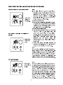
Do not operate or stop the
unit by inserting or pulling
out the power plug.
Do not operate with wet
hands or in damp
environment.
Do not allow water to run
into electric parts.
Do not use the socket if it is
loose or damaged.
Do not use the power cord
close to heating appliances.
Do not damage or use an
unspecified power cord.
Do not direct airflow at
room occupants only.
Always install circuit
breaker and a dedicated
power circuit.
Do not open the unit
during operation.
Do not use the power cord near
flammable gas or combustibles, such
as gasoline, benzene, thinner, etc.
Do not disassemble or modify unit.
!
!
!
!
!
!
WARNING
!
2
!
!!

!
CAUTION
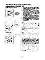
When the air filter is to be
removed, do not touch the
metal parts of the unit.
It may cause an injury.
Do not clean unit when
power is on as it may cause
fire and electric shock, it may
cause an injury.
Operation with windows
opened may cause wetting
of indoor and soaking of
household furniture.
When the unit is to be
cleaned, switch off, and turn
off the circuit breaker.
Stop operation and close
the window in storm or
hurricane.
Use caution when unpacking and
installing. Sharp edges could cause injury.
Do not clean the air
conditioner with water.
Water may enter the unit and
degrade the insulation. It may
cause an electric shock.
This could injure the pet or
plant.
It may cause electric shock
and damage.
Do not put a pet or house
plant where it will be
exposed to direct air flow.
Hold the plug by the head
of the power plug when
taking it out.
Ventilate the room well when
used together with a stove,
etc.
An oxygen shortage may occur.
Do not use this air conditioner to
preserve precision devices, food,
pets, plants, and art objects.
It may cause deterioration of
quality, etc.
It may cause failure of product
or fire.
Do not use for special
purposes.
Turn off the main power
switch when not sing the
unit for a long time.
u
If water enters the unit, turn the unit off at the power
outlet and switch off the circuit breaker. Isolate
supply by taking the power-plug out and contact a
qualified service technician.
3
!
!
!
!
!
!
!
It may cause failure of
appliance or accident.
Appearance may be
deteriorated due to change
of product color or
scratching of its surface.
Do not place obstacles
around air-inlets or inside
of air-outlet.
Do not use strong deter-
gent such as wax or
thinner but use a soft cloth.
If bracket is damaged, there
is concern of damage due to
falling of unit.
There is danger of fire or
electric shock.
Ensure that the installation bracket of
the outdoor appliance is not damaged
due to prolonged exposure.
Do not place heavy object on the
power cord and ensure that the cord
is not compressed.
Operation without filters may
cause failure.
It contains contaminants and
could make you sick.
Always insert the filters
securely. Clean filter once
every two weeks.
Do not drink water drained
from air conditioner.
!
!

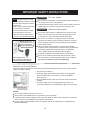
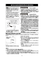
IMPORTANT SAFETY INSTRUCTIONS
Be sure the electrical service is adequate for the model you have
chosen. This information can be found on the serial plate, which
is located on the side of the cabinet and behind the grille.
Be sure the air conditioner is properly grounded. To minimize
shock and fire hazards, proper grounding is important. The power
cord is equipped with a three-prong grounding plug for protection
against shock hazards.
Your air conditioner must be used in a properly grounded wall
receptacle. If the wall receptacle you intend to use is not adequately
grounded or protected by a time delay fuse or circuit breaker,
have a qualified electrician install the proper receptacle.
Ensure the receptacle is accessible after the unit installation.
Do not run air conditioner without side protective cover in place.
This could result in mechanical damage within the air conditioner.
Do not use an extension cord or an adapter plug.
WARNING
For your safety
Do not store or use gasoline or other flammable vapors and liquids in
the vicinity of this or any other appliance.
Avoid fire hazard or electric shock. Do not use an extension cord or an
adaptor plug. Do not remove any prong from the power cord.
WARNING
Electrical Information
NOTE The power supply cord with
this air conditioner contains a current
detection device designed to reduce
the risk of fire.
Please refer to the section Operation
of Current Device for details.
In the event that the power supply
cord is damaged, it cannot be
repaired-it must be replaced with a
cord from the Product Manufacturer.
,
,
Do not, under any
circumstances, cut,
remove, or bypass
the grounding prong.
Power supply cord
with 3-prong grounding plug
and current detection device
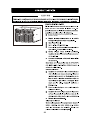
Operation of Current Device
The power supply cord contains a current device that senses damage to the power cord. To test your power
supply cord do the following:
1. Plug in the Air Conditioner.
2. The power supply cord will have TWO buttons on the plug head.
Press the TEST button, you will notice a click as the RESET
button pops out.
3. Press the RESET button, again you will notice a click as the button
engages.
4. The power supply cord is now supplying electricity to the unit.
(On some products this it also indicated by a light on the plug head.)
Do not use this device to turn the unit on or off.
Always make sure the RESET button is pushed in for correct operation.
The power supply must be replaced if it fails reset when either the TEST button is pushed, or it cannot be
reset. A new one can be obtained from the product manufacturer.
If power supply cord is damaged, it cannot be repaired. It MUST be replaced by one
NOTES:
obtained from the
product manufacturer.
4

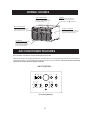
NORMAL SOUNDS
AIR CONDITIONER FEATURES
Sound of Rushing Air
At the front of the unit, you may
hear the sound of rushing air
being moved by the fan
High Pitched Chatter
High efficiency compressors
may have a high pitched chatter
during the cooling cycle.
Gurgle/Hiss
Gurgling or hissing noise may
be heard due to refrigerant
passing through evaporator
during normal operation.
Pinging or Switching
Droplets of water hitting condenser
during normal operation may cause
pinging or switching sounds.
Before you begin, thoroughly familiarize yourself with the control panel and remote as shown below
and all its functions, then follow the symbol for the functions you desire. The unit can be controlled
by the unit control alone or with the remote.
Vibration
Unit may vibrate and make noise
because of poor wall or window
construction or incorrect installation.
ELECTRONIC CONTROL OPERATING INSTRUCTIONS
UNIT CONTROL
5
Energy
Saver
Sleep Timer
Temp Temp
Timer Check
Filter
High Med
Mode
Timer
Auto Cool On Off
Auto Low
Fan
On/Off
Fan
Dry
S
Model)
(Cool Only


AIR CONDITIONER FEATURES(CONTINUED)
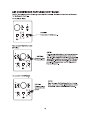
TO SELECT THE
OPERATING MODE:
Press the Mode
button.
DO THIS:
To choose operating mode, press the Mode button.
Each time you press the button, a mode is selected
in a sequence that goes from Auto, Cool, Dry , Heat
(Cooling only models without) and Fan. The indicator
light beside will be illuminated and remained on
once the mode is selected.
NOTE:
To operate on Auto feature:
In this mode, the fan speed cannot be adjusted, it
starts automatically at a speed according to the
room temperature. If the room does not get too
warm, it will stay at Low speed.
To operate on Fan Only:
Use this function only when cooling is not desired,
such as for room air circulation or to exhaust stale
air(on some models). (Remember to open the vent
during this function, but keep it closed during
cooling for maximum cooling efficiency.) You can
choose any fan speed you prefer.
During this function, the display will show the actual
room temperature, not the set temperature as in the
cooling mode.
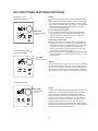
TO USE THE ENERGY
SAVER FEATURE:
Press the button
DO THIS:
In this mode, the fan will continue to run for 3 minutes
after the compressor shuts off. The fan then cycles
on for 2 minutes at 10 minute intervals until the room
temperature is above the set temperature, at which
time the compressor turns back on and cooling starts.
NOTE:
SLEEP FEATURE:
Press Sleep
button
DO THIS:
In this mode the selected temperature will increase by
2 degrees F 30 minutes after the mode is selected.
The temperature will then increase by another 2
degrees F after an additional 30 minutes. This new
temperature will be maintained for 7 hours before it
returns to the originally selected temperature. This
ends the Sleep mode and the unit will continue to
operate as originally programmed. The Sleep mode
program can be cancelled at any time during operation
by again pressing the Sleep button.
NOTE:
7
Energy
Saver
Sleep Timer
Temp
Mode
Timer
Auto Cool On Off
Energy
Saver
Sleep Timer
Temp
Mode
Timer
Auto Cool On Off
Energy
Saver
Sleep Timer
Temp
Mode
Timer
Auto Cool On Off
Fan
Dry
Fan
Dry
Fan
Dry
Fan
Dry
SS
S
S

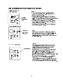
FOLLOW ME
S
Follow Me
Follow Me
Follow Me
Follow Me

1
2
86

10
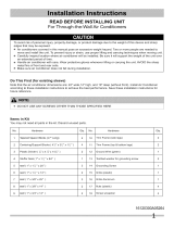
INSTALLATION INSTRUCTIONS(CONTINUED)
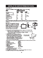
How to Install
1. Identify the wall-sleeve brand for your installation, from the chart below.
White-Westinghouse
Frigidaire
Carrier
General Electric/Hotpoint
Whirlpool
Fedders/Emerson
Sears/Kenmore
Carrier
Emerson/Fedders
Friedrich
Brand Wall Sleeve Dimensions
Width Height Depth
(inches)
1
/
2
25 15 16,17 or 22
1
/
2
1
/
4
26 15 16
7
/
8
5
/
8
7
/
8
25 16 17 or 23
1
/
8
1
/
2
3
/
4
27 16 16 or 19
3
/
4
3
/
4
3
/
4
25 16 18
5
/
8
7
/
8
3
/
4
26 15 15
3
/
4
/
27 16 16
3
4
3
/
4
NOTE: All wall sleeves used to mount the new Air Conditioner must be in sound structural condition
and have a rear grille that securely attaches to sleeve, or rear flange that serves as a stop for the Air
Conditioner.
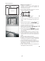
CAUTION:
RUBBER
CLAMP
When installation is complete,
replacement unit MUST have a rearward
slope as shown. And ensure the
on the chassis at the back of the
unit had been removed before place the
unit into the sleeve. But if the rearward
slope is more than 1 2 , do not remove
the Rubber Clamp before installation.
REAR
LEVEL
FRONT
UNIT
Wall
Sleeve
1
/
4 to
5
/
16
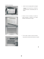
2. Remove old Air Conditioner from wall sleeve and prepare wall sleeve as follows:
--- Clean interior (do not disturb seals).
--- Wall sleeve must be securely fastened in wall before installing Air Conditioner.
Drive more nails or screws through sleeve, into wall, if needed.
--- Repair paint if needed.
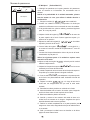
3. If not existing, drill a 3/16 clearance hole for
grounding screw through left side of wall sleeve,
in a clear area about 3 inches maximum (to suit)
back from front edge of sleeve as shown below.
Next attach ground wire inside sleeve, using
grounding screw and nut. Pull loose end of ground
wire out front of sleeve, and temporarily bend it
down and around lower edge of sleeve.
Wall sleeve to unit
sleeve grounding
1
3
Max.
3/16
Hole
4. Prepare the wall sleeve for installation of the new unit per the following Brand instructions.
#1 Emerson 15 Deep
#2 Fedders 19 Deep
#3 Fedders or Friedrich 16 Deep
#4 General Electric/Hotpoint 16 Deep
#5 Sears or Carrier 18 Deep
#6 Whirlpool 17 Deep
#7 Whirlpool 23 Deep
#8 White-Westinghouse/ 16 +17 Deep
Frigidaire/Carrier
#9 White-Westinghouse/Frigidaire 22 Deep
3
/
4
/
4
7
/
8
/
3
/
4
/
4
5
/
8
/
1
/
8
/
3
/
4
/
4
5. Install new unit into wall sleeve.
6. To attach ground wire to the new unit, remove the screw from the left side front.
7. Assemble and install the Trim Frame (see instruction).
/
RUBBER
CLAMP

11
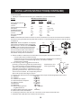
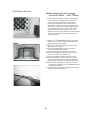
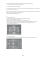
This units increased performance characteristics meant;
1. The rear air intake moved to the opposite side,
2. The depth had to be increased.
It is very important that these installation instructions are followed so your unit can operate at
maximum efficiency.
If this is an existing sleeve, and there is an existing rear grille, the louvers will have to be bent
as per the instructions at the beginning of each section.
If this proves too difficult to accomplish;
1. Remove the existing grille.
2. Place the included aluminum grille towards the rear of the unit.
3. Mark through the hole positions.
4. Drill through the sleeves flanges with a 1/8 drill bit.
5. Attached the new grille with self-threading screws and washers(not included).
6. It is VERY IMPORTANT that the partition be placed on the left side of the sleeve
as shown below.
1. Remove the existing grille.
2. Use plastic grille and secure to sleeves flanges using existing screws and washers.
EITHER
OR

12
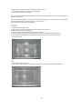
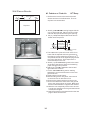
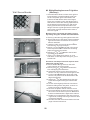
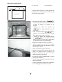
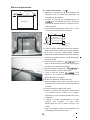
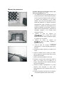
Wall Sleeve Brands:
Top View
Rear Louvers
7
60
60
#1 Emerson 15 Deep
1. Redirect the louvers at the back of the wall
sleeve as shown in the illustration. The use
of pliers is recommended.
2. Attach(1)1 x3/8 x25 long seal in the center at
the top of the sleeve. Remove the backing paper
and press into position.
3. Attach the (2) 1 x3/8 x14 long seals to the
left and right sides of the sleeve.
4. Cut the 1 x3/8 x25 long seal to 14 long, and
attach it to the vertical section of the rear grille
as shown.
5. Attach (2)4 x3 x1 centering/support blocks
one on each side wall. Place in center of side
wall with the tapered end facing the opening.
6. Gently slide unit into sleeve.
7. Before sliding all-the-way back, remove 2nd
screw from front on left side of unit.
8. Remove the plastic washer from the screw.
9. Screw and attach the other end of the ground
wire to the unit as shown in picture. Make sure
that the toothed washer is against the cabinet.
10.Slide the unit completely to the rear to ensure
a good seal, making sure the ground wire does
not become tangled.
11.Seal & Frame the unit as described on the last
page of these instructions.
1
/
2
1
/
2
1
/
2
1
/
2
1
/
2
1
/
2

13
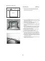
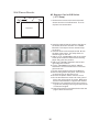
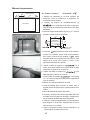
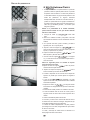
Wall Sleeve Brands:
Top View
Rear Louvers
7
60
60
#2 Fedders 19 Deep
1. Redirect the louvers at the back of the wall
sleeve as shown in the illustration. The use
of pliers is recommended.
3
4
/
2. Attach(1)4 x3 x1 centering/support blocks
one on each side wall. Place in center of side
wall with the tapered end facing the opening.
3. Cut (2) 17 Tapered Spacer Blocks as shown
below into two pieces.
4. The 4 section is placed in front of the rib on
base with the tapered end facing the back of
the sleeve. The remaining portion will be
placed behind the rib again sloping toward
the rear of the sleeve. This helps induce a
rearward slope on the unit.
5. Attach (1)4 x3/8 x25 long seal in the center
at the top of the sleeve. Remove the backing
paper and press into position.
6. Attach (2) 1 x3/8 x14 seals to the left and
right sides of the sleeve.
7. Cut the 1 x3/8 x25 long seal to 14 long
and attach it to the vertical section of the rear
grille as shown.
8. Gently slide unit into sleeve.
9. Before sliding all-the-way back, remove 2nd
screw from front on left side of unit.
10. Remove the plastic washer from the screw.
11. Screw and attach the other end of the ground
wire to the unit as shown in picture. Make sure
that the toothed washer is against the cabinet.
12.Slide the unit completely to the rear to ensure
a good seal, making sure the ground wire does
not become tangled.
13.Seal & Frame the unit as described on the last
page of these instructions.
1
/
2
1
/
2
1
/
2
1
/
2
1
/
2
/
2
1
/
2
/
2
Cut Here
3
/
4
17
Tapered Spacer Block
1
Protection Paper
Backing

14
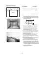
Wall Sleeve Brands:
Top View
Rear Louvers
7
60
60
#3 Fedders or Friedrich 16 Deep
1. Redirect the louvers at the back of the wall
sleeve as shown in the illustration. The use
of pliers is recommended.
3
4
/
2. Attach(1)4 x3 x1 centering/support blocks
one on each side wall. Place in center of side
wall with the tapered end facing the opening.
3. Cut (2) 17 Tapered Spacer Blocks as shown
below into three pieces.
4. The 2 section is placed in front of the rib on
base with the tapered end facing the back of
the sleeve. Cut the remaining portion to 12
and placed behind the rib again sloping toward
the rear of the sleeve. This helps induce a
rearward slope on the unit.
5. Attach (1)1 x3/8 x25 long seal in the center
at the top of the sleeve. Remove the backing
paper and press into position.
6. Attach (2) 1 x3/8 x14 seals to the left and
right sides of the sleeve.
7. Cut the 1 x3/8 x25 long seal to 14 long
and attach it to the vertical section of the rear
grille as shown.
8. Gently slide unit into sleeve.
9. Before sliding all-the-way back, remove 2nd
screw from front on left side of unit.
10. Remove the plastic washer from the screw.
11. Screw and attach the other end of the ground
wire to the unit as shown in picture. Make sure
that the toothed washer is against the cabinet.
12.Slide the unit completely to the rear to ensure
a good seal, making sure the ground wire does
not become tangled.
13.Seal & Frame the unit as described on the last
page of these instructions.
1
/
2
1
/
2
1
/
2
1
/
2
1
/
2
/
2
1
/
2
/
2
Cut Here
3
/
4
17
Tapered Spacer Block
1
Protection Paper
Backing
12-1/2
2-1/2
1
/
2
1
/
2

15
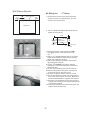
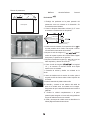
Wall Sleeve Brands:
Top View
Rear Louvers
7
60
60
#4 General Electra/Hotpoint 16 Deep
1. Redirect the louvers at the back of the wall
sleeve as shown in the illustration. The use
of pliers is recommended.
7
8
/
2. Cut (2) 17 Tapered Spacer Blocks as shown
below into two pieces.
3. Install as shown with the tapered end from
the back of the sleeve. This helps induce a
rearward slop on the unit.
4. Attach (1)1 x3/8 x25 long seal in the center
at the top of the sleeve. Remove the backing
paper and press into position.
5. Attach (2) 1 x3/8 x14 seals to the left and
right sides of the sleeve.
6. Cut the 1 x3/8 x25 long seal to 14 long
and attach it to the vertical section of the rear
grille as shown.
7. Center unit and gently slide unit into sleeve.
8. Before sliding all-the-way back, remove 2nd
screw from front on left side of unit.
9. Remove the plastic washer from the screw.
10. Screw and attach the other end of the ground
wire to the unit as shown in picture. Make sure
that the toothed washer is against the cabinet.
11.Slide the unit completely to the rear to ensure
a good seal, making sure the ground wire does
not become tangled.
12.Seal & Frame the unit as described on the last
page of these instructions.
1
/
2
1
/
2
1
/
2
3
/
4
17
Tapered Spacer Block
1
Protection Paper
Backing
Cut Here
13
1
/
2

16
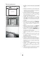
Wall Sleeve Brands:
Top View
Rear Louvers
7
60
60
#5 Sears or Carrier 51S Series
( 18 Deep)
1. Redirect the louvers at the back of the wall
sleeve as shown in the illustration. The use
of pliers is recommended.
5
8
/
2. Install (2) tapered spacer blocks to the floor of
the sleeve as shown. DO NOT CUT THERE
BLOCKS. This helps induce a rearward slop
on the unit.
3. Install as shown with the tapered end from
the back of the sleeve. This helps induce a
rearward slop on the unit.
4. Attach (1)1 x3/8 x25 long seal in the center
at the top of the sleeve. Remove the backing
paper and press into position.
5. Attach (2) 1 x3/8 x14 seals to the left and
right sides of the sleeve.
6. Cut the 1 x3/8 x25 long seal to 14 long
and attach it to the vertical section of the rear
grille as shown.
7. Center unit and gently slide unit into sleeve.
8. Before sliding all-the-way back, remove 2nd
screw from front on left side of unit.
9. Remove the plastic washer from the screw.
10. Screw and attach the other end of the ground
wire to the unit as shown in picture. Make sure
that the toothed washer is against the cabinet.
11.Slide the unit completely to the rear to ensure
a good seal, making sure the ground wire does
not become tangled.
12.Seal & Frame the unit as described on the last
page of these instructions.
1
/
2
1
/
2
1
/
2
1
/
2

17
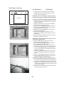
Wall Sleeve Brands:
Top View
Rear Louvers
7
60
60
#6 Whirlpool 17 Deep
1. Redirect the louvers at the back of the wall
sleeve as shown in the illustration. The use
of pliers is recommended.
1
8
/
2. Cut (2) 17 Tapered Spacer Blocks as shown
below into two pieces.
3. Install to the floor of the sleeve as shown.
This helps induce a rearward slop on the
unit.
4. Attach (1)1 x3/8 x25 long seal in the center
at the top of the sleeve. Remove the backing
paper and press into position.
5. Attach (2) 1 x3/8 x14 seals to the left and
right sides of the sleeve.
6. Cut the 1 x3/8 x25 long seal to 14 long
and attach it to the vertical section of the rear
grille as shown.
7. Center unit and gently slide unit into sleeve.
8. Before sliding all-the-way back, remove 2nd
screw from front on left side of unit.
9. Remove the plastic washer from the screw.
10. Screw and attach the other end of the ground
wire to the unit as shown in picture. Make sure
that the toothed washer is against the cabinet.
11.Slide the unit completely to the rear to ensure
a good seal, making sure the ground wire does
not become tangled.
12.Seal & Frame the unit as described on the last
page of these instructions.
1
/
2
1
/
2
1
/
2
3
/
4
17
Tapered Spacer Block
1
Protection Paper
Backing
Cut Here
13
1
/
2

Wall Sleeve Brands:
Top View
Rear Louvers
7
60
60
#7 Whirlpool ( 23 Deep)
1. Redirect the louvers at the back of the wall
sleeve as shown in the illustration. The use
of pliers is recommended.
1. Place (2) 1 x1 x14 seals against each side.
2. Gently slide unit in and check if amount extend-
ing from the sleeve is sufficient once the trim
frame is attached.
3. If position is Ok, remove unit and proceed to
the next step. If not go to step 8.
4. Attach (1)1 x1 x25 long seal in the center
at the top of the sleeve. Remove the backing
paper and press into position.
5. Attach (2) 1 x1 x14 seals to the left and
right sides of the sleeve.
6. Cut the 1 x1 x25 long seal to 14 long
and attach it vertically to the rear grill 7 from
the left side.
7. Attach the tapered spacer blocks to the floor of
the sleeve. Now go to step 13.
8. Attach 1 x x14 long seal over the solid
vertical portion of the rear grille.
9. Attach (2) 4 x3 x1 foam blocks with the
slot overlapping the seal above.
10. Install the divider into the slots of the foam
blocks. You may need to trim the length to size.
11. Cut the 1 x1 x25 seal to fit the top of the
sleeve. The pieces must be fitted flush to the
edge of the divider.
12. Attach (2) 1 x1 x14 seals along the side
of the sleeve again making sure all seal are
flush.
13. Center unit and gently slide unit into sleeve.
14. Before sliding all-the-way back, remove 2nd
screw from front on left side of unit.
15. Remove the plastic washer from the screw.
16. Screw and attach the other end of the ground
wire to the unit as shown in picture. Make sure
that the toothed washer is against the cabinet.
17.Slide the unit completely to the rear to ensure
a good seal, making sure the ground wire does
not become tangled.
18.Seal & Frame the unit as described on the last
page of these instructions.
Use these next steps if the unit requires extra
extension into the room.
1
/
2
1
/
2
1
/
2
1
/
2
Because of the increased unit depth, first try
dry fitting using the method described below:
1
/
2
1
/
2
1
/
2
1
/
2
1
/
2
3
/
4
1
/
2
1
/
2
1
/
2
1
/
2
1
/
2
1
/
2
1
/
2
18

Wall Sleeve Brands:
#8 White Westinghouse/Frigidaire/
Carrier 52F Series ( 16 +17 Deep)
1. If the wall sleeve does not have a rear grille or
louvered panel, install the plastic grille from
the kit. The plastic grille is mounted to the
inside of the wall sleeve at the rear flanges.
There are (4) plastic nuts in the flanges of the
wall sleeve. If some are missing replacements
are included in the accessory kit, and can be
simply pressed into the square holes in the
flanges. Place the grille against the rear flanges
and use the (4) large washers and screws to
secure the grille.
2. Attach (1)1 x3/8 x25 long seal in the center
at the top of the sleeve. Remove the backing
paper and press into position.
3. Attach (2) 1 x3/8 x14 seals to the left and
right sides of the sleeve.
4. Cut the 1 x3/4 x14 long seal vertically 7
from the left side of the sleeve.
5. Center unit and gently slide unit into sleeve.
6. Before sliding all-the-way back, remove 2nd
screw from front on left side of unit.
7. Remove the plastic washer from the screw.
8. Screw and attach the other end of the ground
wire to the unit as shown in picture. Make sure
that the toothed washer is against the cabinet.
9. Slide the unit completely to the rear to ensure
a good seal, making sure the ground wire does
not become tangled.
10.Seal & Frame the unit as described on the last
page of these instructions.
1
/
2
1
/
2
1
/
2
19

Wall Sleeve Brands:
#9 White Westinghouse or Frigidaire
( 23 Deep)
2. Place (2) 1 x1 x14 seals against each side.
3. Gently slide unit in and check if amount extend-
ing from the sleeve is sufficient once the trim
frame is attached.
4. If position is Ok, remove unit and proceed to
the next step. If not go to step 8.
5. Attach (1)1 x1 x25 long seal in the center
at the top of the sleeve. Remove the backing
paper and press into position.
6. Attach (2) 1 x1 x14 seals to the left and
right sides of the sleeve.
7. Cut the 1 x1 x25 long seal to 14 long
and attach it vertically to the rear grill 7 from
the left side.
8. Attach 1 x x14 long seal over the solid
vertical portion of the rear grille.
9. Attach (2) 4 x3 x1 foam blocks with the
slot overlapping the seal above.
10. Install the divider into the slots of the foam
blocks. You may need to trim the length to size.
11. Cut the 1 x1 x25 seal to fit the top of the
sleeve. The pieces must be fitted flush to the
edge of the divider.
12. Attach (2) 1 x1 x14 seals along the side
of the sleeve again making sure all seal are
flush.
13. Center unit and gently slide unit into sleeve.
14. Before sliding all-the-way back, remove 1st
screw from front on left side of unit.
15. Remove the plastic washer from the screw.
16. Screw and attach the other end of the ground
wire to the unit as shown in picture. Make sure
that the toothed washer is against the cabinet.
17.Slide the unit completely to the rear to ensure
a good seal, making sure the ground wire does
not become tangled.
18.Seal & Frame the unit as described on the last
page of these instructions.
Use these next steps if the unit requires extra
extension into the room.
1
/
2
1
/
2
1
/
2
1
/
2
Because of the increased unit depth, first try
dry fitting using the method described below:
1
/
2
1
/
2
1
/
2
1
/
2
1
/
2
3
/
4
1
/
2
1
/
2
1
/
2
1
/
2
1
/
2
1
/
2
1
/
2
1. If the wall sleeve does not have a rear grille or
louvered panel, install the plastic grille from
the kit. The plastic grille is mounted to the
inside of the wall sleeve at the rear flanges.
There are (4) plastic nuts in the flanges of the
wall sleeve. If some are missing replacements
are included in the accessory kit, and can be
simply pressed into the square holes in the
flanges. Place the grille against the rear flanges
and use the (4) large washers and screws to
secure the grille.
20

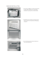
FINISHING INSTALLATION:
1. Install the 1 x1 x84 long stuffer-seal between
the wall-sleeve and the unit. A flat-bladed
screwdriver or putty knife is recommended.
1
/
2
2. Assemble the trim frame by inserting top and
bottom pieces into side pieces and snapping
into place.
3. Pull cord through trim frame then slide over
unit until flush with wall.
21

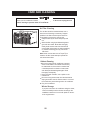
CARE AND CLEANING
Clean your air conditioner occasionally to keep it looking new. Be sure to unplug the unit
before cleaning to prevent chock or fire hazards.
CAUTION
Air Filter Cleaning
The air filter should be checked at least once a
month to see if cleaning is necessary. Trapped
particles in the filter can build up and cause an
accumulation of frost on the cooling coils.
Grasp the filter by the center and pull up and
out.
Wash the filter using liquid dishwashing deter-
gent and warm water. Rinse filter thoroughly.
Gently shake excess water from the filter. Be
sure the filter is thoroughly dry before replacing.
Or, instead of washing you may vacuum the
filter clean.
Never use hot water over 40 C(104 F) to
clean the air filter. Never attempt to operate the
unit without the air filter.
Be sure to unplug the air conditioner to prevent
shock or fire hazard. The cabinet and front may
be dusted with an oil-free cloth or washed with
a cloth dampened in a solution of warm water
and mild liquid dishwashing detergent. Rinse
thoroughly and wipe dry.
Never use harsh cleaners, wax or polish on the
cabinet front.
Be sure to wring excess water from the cloth before
wiping around the controls. Excess water in or around
the controls may cause damage to the air conditioner.
Plug in air conditioner.
If you plan to store the air conditioner during the winter,
remove it carefully from the window according to the
installation instructions. Cover it with plastic or return it
to the original carton.
Note:
。 。
Cabinet Cleaning
Winter Storage
22

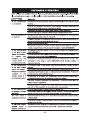
Before calling for service, review this list. It may save you time and expense. This list includes common
occurrences that are not the result of defective workman-ship or materials in this appliance.
Solution
Air conditioner
does not start
Wall plug disconnected. Push plug firmly into wall outlet.
House fuse blown or circuit breaker tripped. Replace fuse with time delay type or
reset circuit breaker.
Plug Current Device Tripped. Press the RESET button.
TROUBLESHOOTING TIPS
Problem
Air from unit does
not feel cold
enough
Reset to a Lower temperature.
Room temperature below 17 C(62 F). Cooling may not occur until room temperature
rises above 17 C(62 F).
Thermostat set too cold for night-time cooling. To defrost the coil, set to FAN ONLY
mode. Then, set temperature to a Higher setting.
Temperature sensing element touching cold coil, located behind air filter. Straighten
tube away from coil.
Air filter may be dirty. Clean filter. Refer to Care and Cleaning section. To defrost,
set to FAN ONLY mode.
Dirty air filter- air restricted. Clean air filter. Refer to Care and Cleaning section.
Unit recently turned on in hot room. Allow additional time to remove Stored heat from
walls, ceiling, floor and furniture.
Control is OFF. Turn Control ON and set to desired setting.
O
O
O
O
Air conditioner
cooling, but room
is too warm- ice
forming on cooling
coil behind
decorative front.
Outdoor temperature below 17 C(62 F). To defrost the coil, set FAN ONLY mode.
O
O
Air conditioner
cooling, but room
is too warm- NO
ice forming on
cooling coil behind
decorative front.
Temperature is set too High, set temperature to a Lower setting.
Air directional louvers positioned improperly. Position louvers for better air distribution.
Front of units is blocked by drapes, blinds, furniture, etc. - restricts air distribution.
Clear blockage in front of unit.
Doors, windows, registers, etc. Open- cold air escapes. Close doors, windows, registers.
Compressor shut-off by changing modes. Wait approximately 3 minutes and listen for
compressor to restart when set in the COOL mode.
Air conditioner turns on
and off rapidly
Noise when unit is
cooling
Water dripping
INSIDE when
unit is cooling.
Improper installation. Tilt air conditioner slightly to the outside to allow water drainage.
Refer to installation instructions - check with installer.
Dirty air filter- air restricted. Clean air filter.
Air movement sound. This is normal . If too loud, set to a slower FAN setting.
Outside temperature extremely hot. Set FAN speed to a Higher setting to bring air past
cooling coils more frequently.
Window vibration - poor installation. Refer to installation instructions or check with installer.
23

Solution
Problem
Water dripping
OUTSIDE when
unit is cooling.
Unit removing large quantity of moisture from humid room. This is normal during
excessively humid days.
Remote Sensing
Deactivating
Prematurely
(some models)
Remote control not located within range. Place remote control within 20 feet & 180 ,
radius of the front of the unit.
Remote control signal obstructed. Remove obstruction.
Room too cold
Set temperature too low. Increase set temperature.
24


KSTAT12-1A
KSTAT12-2A

23


S


S
S
S

S

1
2
86


Las características de rendimiento aumentadas de la presente unidad significaban:
1. La entrada de aire trasera moviera al lado opuesto.
2. La profundidad había que ser aumentada.
Es muy importante que estas instrucciones de instalación estén segidas para que su unidad puede
funcionar con la máxima eficiencia.
Si esto es una funda existentes, y hay una parrilla trasera existente, las rejillas tendrán que ser dobladas
según las instrucciones al principio de cada sección.
Si esto resulta demasiado difícil de lograr;
O
1. Quite la rejilla existente.
2. Coloque la rejilla de aluminio incluida hacia la parte trasera de la unidad.
3. Marque a través de las posiciones agujero.
4. Taladre a través de las bridas de funda con un pedacito de taladro 1/8.
5. Conecte la nueva rejilla con los tornillos de rosca autoroscante y las arandelas (no incluidas).
6. Es MUY IMPORTANTE que la partición esté colocada al lado izquierdo de la funda
como se m
uestra a continuación.
O
1. Quite la rejilla existente.
2. Utilice la rejilla de plástico y la une a las bridas de funda con tornillos y arandelas existentes.

Marcas de pasamuros
#1 Emerson Profundidad 15’’
1. Redirigir las persianas en la parte posterior del
pasamuros como se muestra en la ilustración. Se
recomienda usar el alicates.
2. Adjunte el sello de longitud (1) en
el centro de la parte superior de la funda. Quite
el papel de soporte y lo presione en su
posición.
3. Adjunte los sellos de longitud (2)
a los lados izquierdo y derecho
de la funda.
4. Corte el sello de longitud a la
longitud 14’’, y lo conecte a la sección vertical
de la rejilla trasera como se muestra.
5. Conecte los bloques de centralizar/soporte
(2) x1 uno a cada lado de la
pared. Coloque en el centro de la pared lateral
con el extremo cónico hacia la apertura.
6. Deslice con cuidado la unidad en la funda.
7. Antes de deslizar todo el camino de vuelta,
quite el segundo tornillo de frente sobre el lado
izquierdo de la unidad.
8. Quite la arandela de plástico del tornillo.
9. Atornille y conecte el otro extremo del cable de
tierra a la unidad como se muestra en la
imagen. Asegúrese de que la arandela
dentada está contra el gabinete.
10. Deslice la unidad completamente a la parte
posterior para asegurar
un buen sello, asegurándose de que el cable de
tierra no se enrede.
11. Selle y enmarque la unidad como se describe
en la última página de estas instrucciones.
Rejillas Traseras
Vista Superior

Marcas de pasamuros
#2 Fedders Profundidad 19
1. Redirigir las persianas en la parte posterior del
pasamuros como se muestra en la ilustración. Se
recomienda usar el alicates.
2. Conecte los bloques de centralizar/soporte (1)
uno a cada lado de la pared. Coloque en
el centro de la pared lateral con el extremo cónico
hacia la apertura.
3. Corte los bloques distanciador cónicos (2) 17’’ como
se muestra a continuación en dos piezas.
4. La sección 4”está colocada en frente de la costilla en
la base con el extremo cónico hacia la parte posterior
de la funda. La porción restante estará colocada
detrás de la costilla inclinada hacia la parte trasera de
la funda. Esto ayuda a inducir a una pendiente hacia
atrás de la unidad.
5. Adjunte el sello de longitud (1) en el
centro de la parte superior de la funda. Quite el papel
de soporte y lo presione en su posición.
6. Adjunte los sellos de longitud (2) a
los lados
izquierdo y derecho de la funda.
7. Corte el sello de longitud a la
longitud 14’’, y lo conecte a la sección vertical de la
rejilla trasera como se muestra.
8. Deslice con cuidado la unidad en la funda.
9. Antes de deslizar todo el camino de vuelta, quite el
segundo tornillo de frente sobre el lado izquierdo de
la unidad.
10. Quite la arandela de plástico del tornillo.
11. Atornille y conecte el otro extremo del cable de tierra
a la unidad como se muestra en la imagen.
Asegúrese de que la arandela dentada está contra
el gabinete.
12. Deslice la unidad completamente a la parte
posterior para asegurar un buen sello,
asegurándose de que el cable de tierra no se
enrede.
Rejillas Traseras
Vista Superior
Bloque Distanciador Conico
Soporte de Papel
de Proteccion
13. Selle y enmarque la unidad como se describe en la
última página de estas instrucciones.

Marcas de pasamuros
#3 Fedders o Friedrich Profundidad 16
1. Redirigir las persianas en la parte posterior del
pasamuros como se muestra en la ilustración. Se
recomienda usar el alicates.
2. Conecte los bloques de centralizar/soporte (1)
uno a cada lado de la pared. Coloque en
el centro de la pared lateral con el extremo cónico hacia
la apertura.
3. Corte los bloques distanciador cónicos (2) 17’’ como se
muestra a continuación en dos piezas.
4. La sección está colocada en frente de la costilla en
la base con el extremo cónico hacia la parte posterior
de la funda. Corte la porción restante a y estará
colocada detrás de la costilla inclinada hacia la parte
trasera de la funda. Esto ayuda a inducir a una
pendiente hacia atrás de la unidad.
5. Adjunte el sello de longitud (1) en el
centro de la parte superior de la funda. Quite el papel
de soporte y lo presione en su posición.
6. Adjunte los
sellos de longitud (2) a los
lados izquierdo y derecho de la funda.
7. Corte el sello de longitud a la longitud
14’’, y lo conecte a la sección vertical de la rejilla trasera
como se muestra.
8. Deslice con cuidado la unidad en la funda.
9. Antes de deslizar todo el camino de vuelta, quite el
segundo tornillo de frente sobre el lado izquierdo de la
unidad.
10. Quite la arandela de plástico del tornillo.
11. Atornille y conecte el otro extremo del cable de tierra a
la unidad como se muestra en la imagen. Asegúrese de
que la arandela dentada está contra el gabinete.
12. Deslice la unidad completamente a la parte posterior
para asegurar un buen sello, asegurándose de que el
cable de tierra no se enrede.
13. Selle y enmarque la unidad como se describe en la
Rejillas Traseras
Vista Superior
Soporte de Papel
de Proteccion
Bloque Distanciador Conico
última página de estas instrucciones.

Marcas de pasamuros
#4Punto electrico/Caliente General
Profundidad
1. Redirigir las persianas en la parte posterior del
pasamuros como se muestra en la ilustración. Se
recomienda usar el alicates.
2. Corte los bloques distanciador cónicos (2) 17 como
se muestra a continuación en dos piezas.
3. Instale como se muestra con el extremo cónico de
la parte posterior de la funda. Esto ayuda a inducir
una inclinación hacia atrás de la unidad.
4. Adjunte el sello de longitud (1) en el
centro de la parte superior de la funda. Quite el papel
de soporte y lo presione en su posición.
5. Adjunte los sellos de longitud (2) a los
lados izquierdo y derecho de la funda.
6. Corte el sello de longitud a la longitud
14’’, y lo conecte a la sección vertical de la rejilla
trasera como se muestra.
7. Centralice la unidad y deslice con cuidado en la
funda.
8. Antes de deslizar todo el camino de vuelta, quite el
segundo tornillo de frente sobre
el lado izquierdo de
la unidad.
9. Quite la arandela de plástico del tornillo.
10. Atornille y conecte el otro extremo del cable de
tierra a la unidad como se muestra en la imagen.
Asegúrese de que la arandela dentada está contra el
gabinete.
11. Deslice la unidad completamente a la parte
posterior para asegurar un buen sello, asegurándose
de que el cable de tierra no se enrede.
12. Selle y enmarque la unidad como se describe en la
última página de estas instrucciones.
Rejillas Traseras
Vista Superior
Soporte de Papel
de Proteccion
Bloque Distanciador Conico

Marcas de pasamuros
#5 Sears or Carrier 51S Series (Profundidad
18
5/8’
’)
1. Redirigir las persianas en la parte posterior del
pasamuros como se muestra en la ilustración.
Se recomienda usar el alicates.
2. Instale (2) bloques distanciador cónicos en el
piso de la funda como se muestra. NO CORTE
LOS BLOQUES.Esto ayuda a inducir a una
pendiente hacia atrás de la unidad.
3. Instale como se muestra con el extremo
cónico de la parte trasera de la funda. Esto
ayuda a inducir a una pendiente hacia atrás de
la unidad.
4. Adjunte el sello de longitud (1)
en el centro de la parte superior de la funda.
Quite el papel de soporte y lo presione en su
posición.
5. Adjunte los sellos de longitud (2)
a los lados izquierdo y derecho de la funda.
6. Corte el sello de longitud a la
longitud 14’’, y lo conecte a la sección vertical de
la rejilla trasera como se muestra.
7. Centralice la
unidad y deslice con cuidado en la
funda.
8. Antes de deslizar todo el camino de vuelta, quite
el segundo tornillo de frente sobre el lado
izquierdo de la unidad.
9. Quite la arandela de plástico del tornillo.
10. Atornille y conecte el otro extremo del cable de
tierra a la unidad como se muestra en la imagen.
Asegúrese de que la arandela dentada está
contra el gabinete.
11.Deslice la unidad completamente a la parte
posterior para asegurar un buen sello,
asegurándose de que el cable de tierra no se
enrede.
12. Selle y enmarque la unidad como se describe
en la última página de estas instrucciones.
Rejillas Traseras
Vista Superior

Marcas de pasamuros
#6 Whirlpool Profundidad 17
1/8’’
1. Redirigir las persianas en la parte posterior del
pasamuros como se muestra en la ilustración. Se
recomienda usar el alicates.
2.Corte los bloques distanciador cónicos (2) 17 como se
muestra a continuación en dos piezas.
3. Instale en el piso de la funda como se muestra. Esto
ayuda a inducir a una pendiente hacia atrás de la
unidad.
4. Adjunte el sello de longitud (1) en el
centro de la parte superior de la funda. Quite el papel
de soporte y lo presione en su posición.
5. Adjunte los sellos de longitud (2) a los
lados izquierdo y derecho de la funda.
6. Corte el sello de longitud a la longitud
14’’, y lo conecte a la sección vertical de la rejilla trasera
como se muestra.
7. Centralice la unidad y deslice con cuidado en la funda.
8. Antes de deslizar todo el camino de vuelta, quite el
segundo tornillo de frente sobre el lado izquierdo de la
unidad.
9. Quite la arandela de plástico del tornillo.
10. Atornille y conecte el otro extremo del cable de tierra a
la unidad como se muestra en la imagen. Asegúrese de
que la arandela dentada está contra el gabinete.
11. Deslice la unidad completamente a la parte posterior
para asegurar un buen sello, asegurándose de que el
cable de tierra no se enrede.
12. Selle y enmarque la unidad como se describe en la
última página de estas instrucciones.
Rejillas Traseras
Vista Superior
Soporte de Papel
de Proteccion
Bloque Distanciador Conico

Marcas de pasamuros
#7 Whirlpool (Profundidad 23”)
1. Redirigir las persianas en la parte posterior del pasamuros
como se muestra en la ilustración. Se recomienda usar el
alicates.
Debido a la profundidad de la unidad aumentada, primero
trate de montar en seco, que utiliza el método descrito a
continuación:
1. Coloque los sellos (2) contra cada lado.
2. Deslice con cuidado la unidad y compruebe si la funda que
extiende es suficiente una vez conectado el marco de moldura.
3. Si la posición está bien, quite la unidad y proceda al siguiente
paso. Si no vaya al paso 8.
4. Adjunte el sello de longitud (1) en el centro de
la parte superior de la funda. Quite el papel de soporte y lo
presione en su posición.
5. Adjunte los sellos de longitud (2) a los lados
izquierdo y derecho de la funda.
6. Corte el sello de longitud a la longitud 14, y
lo conecte a la sección vertical de la rejilla trasera 7” como se
muestra.
7. Conecte los bloques distanciador cónicos al piso de
la funda.
Actualmente vaya al paso 13.
Utilice los siguientes pasos si la unidad se requiere extra
extensión en la sala.8.
8.Adjunte el sello de longitud sobre la porción vertical
sólid de la rejilla trasera.
9. Adjunte los bloques de espuma con la ranura
montando por encima del sello arriba.
10. Instale el separador en las ranuras de los bloques de espuma.
Es posible que necesite ajustar la longitud al tamaño.
11. Corte el sello para adaptarse a la parte superior
de la funda. Las piezas deberán estar niveladas al borde del
separador.
12. Adjunte los sellos a lo largo el lado de la
funda otra vez asegurándose de que todo el sello estén
nivelado.
13. Centralice la unidad y deslice con cuidado en la funda.
14. Antes de deslizar todo el camino de vuelta, quite el segundo
tornillo de frente sobre el lado izquierdo de la unidad.
15. Quite la arandela de plástico del
tornillo.
16. Atornille y conecte el otro extremo del cable de tierra a la
unidad como se muestra en la imagen. Asegúrese de que la
arandela dentada está contra el gabinete.
Rejillas Traseras
Vista Superior
17. Deslice la unidad completamente a la parte posterior para
asegurar un buen sello, asegurándose de que el cable de tierra
no se enrede.
18. Selle y enmarque la unidad como se describe en la última
página de estas instrucciones.

Marcas de pasamuros
#8 White Westinghouse/Frigidaire /Carrier 52F
Series (Profundidad 16’’+17
1/2
” )
1. Si el pasamuros tiene una parrilla trasera o el
panel de persianas, instale la rejilla de plástico
del kit. La parrilla de plástico está montada en
el interior del pasamuros en las bridas
traseras. Hay (4) tuercas de plástico en las
bridas del pasamuros. Si algunos recambios
desaparecidos están incluidos en el kit de
accesorios, y pueden ser presionados en los
agujeros cuadrados en las bridas. Coloque la
rejilla contra las bridas traseras y utilice las (4)
arandelas grandes y los tornillos para
asegurar la parrilla.
2. Adjunte el sello de longitud (1)
en el centro de la parte
superior de la funda. Quite el papel de soporte
y lo presione en su posición.
3. Adjunte los sellos de longitud (2)
a los lados izquierdo y
derecho de la funda.
4. Corte el sello de longitud
verticalmente 7” a partir del lado izquierdo de
la funda.
5. Centralice la unidad y deslice con
cuidado en la
funda.
6. Antes de deslizar todo el camino de vuelta,
quite el segundo tornillo de frente sobre el lado
izquierdo de la unidad.
7. Quite la arandela de plástico del tornillo.
8. Atornille y conecte el otro extremo del cable de
tierra a la unidad como se muestra en la
imagen. Asegúrese de que la arandela dentada
está contra el gabinete.
9. Deslice la unidad completamente a la parte
posterior para asegurar un buen sello,
asegurándose de que el cable de tierra no se
enrede.
10. Selle y enmarque la unidad como se describe
en la última página de estas instrucciones.

Marcas de pasamuros
1. Si el pasamuros tiene una parrilla trasera o el panel de
persianas, instale la rejilla de plástico del kit. La parrilla
de plástico está montada en el interior del pasamuros
en las bridas traseras. Hay (4) tuercas de plástico en las
bridas del pasamuros. Si algunos recambios
desaparecidos están incluidos en el kit de accesorios, y
pueden ser presionados en los agujeros cuadrados en
las bridas. Coloque la rejilla contra las bridas traseras y
utilice las (4) arandelas grandes y los tornillos para
asegurar la parrilla.
Debido a la profundidad de la unidad aumentada,
primero trate de montar en seco, que utiliza el método
descrito a continuación:
2. Coloque los sellos (2) contra cada
lado.
3. Deslice con cuidado la unidad y compruebe si la funda
que extiende es suficiente una vez conectado el marco de
moldura.
4. Si la posición está bien, quite la unidad y proceda al
siguiente paso. Si no vaya al paso 8.
5. Adjunte el sello
de longitud (1) en el
centro de la parte superior de la funda. Quite el papel de
soporte y lo presione en su posición.
6. Adjunte los sellos de longitud (2) a los
lados izquierdo y derecho de la funda.
7. Corte el sello de longitud a la longitud
14, y lo conecte a la sección vertical de la rejilla trasera 7”
como se muestra.
Utilice los siguientes pasos si la unidad se requiere
extra extensión en la sala.8.
8.Adjunte el sello de longitud sobre la porción
vertical sólid de la rejilla trasera.
9. Adjunte los bloques de espuma (2) con la
ranura montando por encima del sello arriba.
10. Instale el separador en las ranuras de los bloques de
espuma. Es posible que necesite ajustar la longitud al
tamaño.
11. Corte el sello para adaptarse a la parte
superior de la funda. Las piezas deberán estar niveladas
al borde del se
parador.
12. Adjunte los sellos (2) a lo largo el lado de
la funda otra vez asegurándose de que todo el sello estén
nivelado.
13. Centralice la unidad y deslice con cuidado en la funda.
14. Antes de deslizar todo el camino de vuelta, quite el
segundo tornillo de frente sobre el lado izquierdo de la
unidad.
15. Quite la arandela de plástico del tornillo.
16. Atornille y conecte el otro extremo del cable de tierra a
la unidad como se muestra en la imagen. Asegúrese de que
la arandela dentada está contra el gabinete.
17. Deslice la unidad completamente a la parte posterior
para asegurar un buen sello, asegurándose de que el cable
de tierra no se enrede.
18. Selle y enmarque la unidad como se describe en la
última página de estas instrucciones.

ACABAR DE INSTALAR
1. Instale el sello de empaquetadura de longitud
entre el pasamuros y la unidad. Se
recomienda utilizar un destornillador plano o la
spatula.
2. Monte el marco de moldura por insertar las
piezas superiores e inferiores en las piezas
laterales y introducirlas en su lugar.
3. Tire el cordón a través de marco de moldura,
luego deslice la unidad hasta nivelada con la pared.

Empujar la palanca para el respiradero de ventilación
posición cerrada.
22

23

24

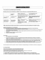
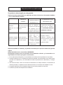
Garantía de Air acondicionado
Su producto está protegido por esta garantía:
Reparaciones bajo garantía deben ser obtenidos de Centro de Servicios al Consumidor de Midea
o con un administrador de Midea.
PERIODO DE
GARANTIA
MIDEA , A TRAVES DE SU
CENTRO DE SERVICIO
AUTORIZADO, VA A
EL CONSUMIDOR VA A SER
RESPONSABLE PARA
GARANTIA
COMPLETA DE 2DO
AÑOS
2DO años a partir de
la
fecha de compra
original
Pago de la totalidad de los
costos de reparación o
reemplazo de las partes de
este dispositivo que se
comprueba defectuosos en
materiales o mano de obra.
Los costos de las llamadas de
servicio que se encuentra
bajo RESPONSABILIDADES DEL
CONSUMIDOR NORMALES
GARANTIA LIMITADA
DE 3DO A 5TO AÑOS
(sistema sellado)
Tercer hasta quinto
Año a partir de la fecha
de compra original
Reparar o reemplazar
cualquier parte en la
Sistema Sellado de
refrigeración (compresor, el
condensador, el evaporador
y el tubo)se comprueban
defectuosos en materiales
de la mano de obra.
Diagnóstico, retirada
y
reinstalación necesarioS delos
costos de los servicios que no sean
con respecto al sistema de
refrigeración Sellado
Repuestos de Midea se utilizarán y se justifican únicamente por el período restante de la garantía
original
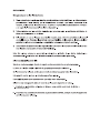
Responsabilidades de los consumidores NORMALES
Esta garantía se aplica sólo a los productos de uso doméstico ordinario, y el consumidor es el
responsable de los temas que figuran a continuación;
1. El uso adecuado del dispositivo, de conformidad con las instrucciones provistas con el producto.
2. Correcta instalación por un profesional de servicio autorizado, de conformidad con las instrucciones
provistas con el dispositivo, y de conformidad con todos los plomería local , electricidad y / o códigos
de gas.
3. Una buena conexión a tierra a una fuente de alimentación de voltaje suficiente, de sustitución de
fusibles quemados, la reparación de los defectos sueltos o las conexiones de cableado en casa.
4. Los gastos para hacer que el dispositivo llegue al centro de la prestación de servicios.
5. Los daños a perfeccionar después de la instalación.

1-866-646-4332.
-
 1
1
-
 2
2
-
 3
3
-
 4
4
-
 5
5
-
 6
6
-
 7
7
-
 8
8
-
 9
9
-
 10
10
-
 11
11
-
 12
12
-
 13
13
-
 14
14
-
 15
15
-
 16
16
-
 17
17
-
 18
18
-
 19
19
-
 20
20
-
 21
21
-
 22
22
-
 23
23
-
 24
24
-
 25
25
-
 26
26
-
 27
27
-
 28
28
-
 29
29
-
 30
30
-
 31
31
-
 32
32
-
 33
33
-
 34
34
-
 35
35
-
 36
36
-
 37
37
-
 38
38
-
 39
39
-
 40
40
-
 41
41
-
 42
42
-
 43
43
-
 44
44
-
 45
45
-
 46
46
-
 47
47
-
 48
48
-
 49
49
-
 50
50
-
 51
51
-
 52
52
-
 53
53
-
 54
54
-
 55
55
-
 56
56


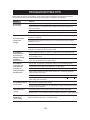
Keystone KSTAT12-1A Manual de usuario
- Tipo
- Manual de usuario
- Este manual también es adecuado para
en otros idiomas
- English: Keystone KSTAT12-1A User manual
Artículos relacionados
Otros documentos
-
GE Appliances AKCQ14DCH El manual del propietario
-
Arctic King AKTW+12CR4-2 Installation & Operation Manual
-
Impecca ITAC10-KSB21 Guía del usuario
-
-
Frigidaire 309000848 Manual de usuario
-
 Kenmore Elite 25377085510 Guía de instalación
-
LG 8170 El manual del propietario
-
-
Frigidaire FHTE143WA2 Manual de usuario
-
Westinghouse 7500400 Instrucciones de operación
