
L
N
DIM +
DIM -
BB
KK
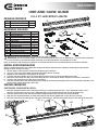
Item # 1004330413
Model # 54598141
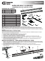
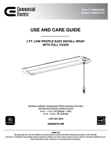
PACKAGE CONTENTS
Part Description Quantity
A Fixture Body 2
B Lens Cover 2
HARDWARE INCLUDED
Part Description Quantity
AA Continuous Linking Bracket 1
BB Mounting Bracket 1
CC Screws for Linking Bracket 4
DD Wire Protection Ring 1
EE Toggle Bolts 4
FF Chains 4
GG Hooks 4
HH Knock Out Cover 2
II Tandem Linking Bracket 2
JJ Plastic Cover - Tandem 2
KK Electrical Box Screw 2
LL Screws for Plastic Cover 2
NOTE: Keep your receipt and these instructions for proof of purchase.
WARNING: RISK OF ELECTRIC SHOCK. Ensure the electricity to the wires you are working on is shut off. Either remove the
fuse or turn off the circuit breaker before removing an existing light fixture or installing the new one.
If you are unfamiliar with electrical installations, we recommend you contact a qualified electrician to do the installation.
USE AND CARE GUIDE
2 X 4 FT. LED STRIP LIGHTS
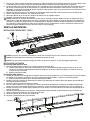
INSTALLATION PREPARATION
Select a suitable location that can support the weight of the fixture. Determine the method for mounting the fixture before
drilling, based on the type of ceiling.
1. Shut off power at the electrical panel before beginning the installation.
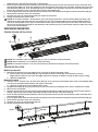
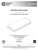
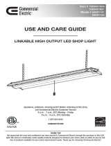
2. Press the sides of the fixture body (A) inward and remove the lens cover (B).
3. Unplug the wire connectors to disconnect the terminal.
4. Place the two fixture bodies (A) on the linking bracket (AA) and secure with the provided screws (CC).
5. Determine which knock out hole in the fixture body (A) to use for wiring the fixture and punch it out with a screwdriver.
6. Place the wire protection rings (DD) into the knock outs.
7. Feed the electrical wires from the electrical box through the mounting bracket (BB). Secure the mounting bracket (BB) to the
electrical box with the mounting screws (KK).
SURFACE MOUNTING
CONTINUOUS CEILING INSTALLATION
1. Mark two keyhole locations on the mounting surface for each fixture body (A). Drill a 1/8 in. pilot hole into the screw
locations marked on the ceiling. Install a toggle bolt (EE) in each drilled mounting hole, but do not tighten fully.
2. Feed the electrical wires from the electrical box through the open knock out hole in the fixture body (A).
3. Align the four mounting keyholes on the fixture body (A) with the four toggle bolts screws (EE) in the ceiling.
4. Once the screw heads are through the large ends of the keyholes, slide the fixture body (A) to the left until the heads of the
A
AA
A
DD
CC
A
B
B
A
+
AA
BB
CC
DD
EE
II
FF
HH
JJ
GG
KK
LL

L
N
DIM +
DIM -
2
toggle bolts (EE) slide into the narrow ends of the keyholes.
5. Insert the hot and neutral (black and white) wires from the electrical box into the wire connectors of the same color wires
from the fixture bodies (A). Insert the ground wire from the electrical box into the wire connector attached to the green wire
from the fixture bodies (A). If a 0-10v dimming circuit is available, insert the purple and gray wires from the electrical box
into the wire connectors of the same color wires from the fixture bodies (A).
6. Insert the ground wire from the electrical box into the wire connector attached to the green wire from the fixture body (A).
7. Reconnect the terminals to the wire connectors.
8. Snap the lens cover (B) onto the fixture body (A). Repeat for 2nd fixture.
9. Restore the power to the electrical box.
NOTE: For Parallel Installation - disconnect the wires with the quick connects. Place the fixture bodies (A) side by side
and punch out the inside knock outs that are 2nd from the end. Put the fixture bodies on the parallel linking brackets (II)
and secure with provided screws (CC). Put the knock out cover (HH) in the knock out hole on the side of the fixture. Push
the wires of the one fixture through the side knock out and reconnect the wires with the quick connects. Attach the plastic
cover (JJ) to each bracket (II).
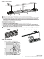
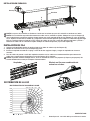
SUSPENDED MOUNTING
TANDEM CEILING INSTALLATION
NOTE:
The installation steps of tandem ceiling is as same as continuous ceiling installation.
NOTE:
Above installation is not suitable for drywall mounting.
NOTE:
For Parallel Installation - Push the wires from one of the fixtures through the side knock out hole.
FF
Hook
Conduit
A
B
II
A
JJ
CC
LL
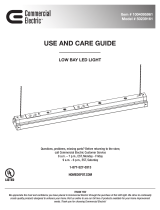
TANDEM INSTALLATION
Mounting to drywall
1. Determine the position for the two toggles to be secured in the drywall mounting surface.
A. Drill four holes, for each fixture body (A), large enough to clear the closed flaps of the butterfly nut on the
toggle bolt (EE). Make sure to fasten the toggle bolt into the butterfly nut before inserting the flaps into the ceiling.
B. Tighten the toggle bolt.
Mounting to wood
2. Drill four 1/16 in. diameter holes, for each fixture body (A), in the ceiling to accommodate hook screws (not included). Make
sure to fasten the combo wood-machine end into the metal hook.
A. Tighten the hook screws (not included) into the wood.
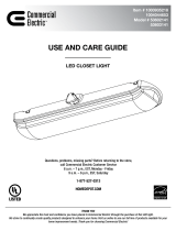
3. Hang the fixture body (A) by placing one chain (FF) over each hook (not included) that has been installed on the ceiling.
4. Adjust chains to level light.
5. Feed the electrical wires from the electrical box through the appropriate conduit based on local electrical code and then
through a pipe clamp (not included) and through the open knock out hole in the fixture body (A).
6. Insert the hot and neutral (black and white) wires from the electrical box into the wire connectors of the same color wires
from the fixture body (A).
7. Insert the ground wire from the electrical box into the wire connector attached to the green wire from the fixture body (A).
8. Reconnect the terminals to the wire connectors.
9. Snap the lens cover (B) onto the fixture body (A).
10. Restore the power to the electrical box.

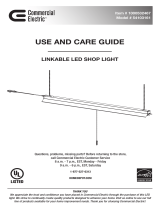
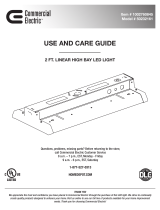
CD:0
1,800
1,500
1,200
900
600
300
300
600
900
1,800
1,500
1,200
180° 170° 160° 150° 140°
130°
120°
110°
100°
90°
80°
70°
60°
50 °
40°30 °20°10°VA:0 °
-0°H
-90°H
Hook
Conduit
HOMEDEPOT.COM
3 Please contact 1-877-527-0313 for further assistance.
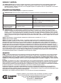
CONTINUOUS INSTALLATION
1. Using a screwdriver, punch out the knock out hole on the sides of both fixture bodies (A).
2. Place the ends of the fixture bodies (A) together.
3. Insert either a type 1/2 threaded coupler through both knock out holes and secure coupler with 2 threaded nuts.
4. Run jumper wires through the threaded coupler or use the wires in the metal conduit to connect the hot and neutral
(black and white) wires from one fixture body (A) to the next.
NOTE: Multiple light fixtures can be connected, up to a maximum of 8 Lights or 4 packs (2 lights per pack). Do not
exceed 400 total watts for interconnected lights.
NOTE:
The installation steps of tandem ceiling is as same as continuous ceiling installation.
NOTE: For Parallel Installation - disconnect the wires with the quick connects. Place the fixture bodies (A) side by
side and punch out the inside knock outs that are 2nd from the end. Put the fixture bodies on the parallel linking
brackets (II) and secure with provided screws (CC). Put the knock out cover (HH) in the knock out hole on the side
of the fixture. Push the wires of the one fixture through the side knock out and reconnect the wires with the quick
connects. Attach the plastic cover (JJ) to each bracket (II).
PARALLEL INSTALLATION
Coupler
B
A
Row mount for end to end combo
LIGHT DISTRIBUTION
POLAR CANDELA DISTRIBUTION

Problem Possible Cause Solution
The fixture will not light. The power is off. Ensure the power supply is on.
The circuit breaker is off. Ensure the circuit breaker is in the on position.
There is a bad connection. Check to ensure proper wire connections are made. Contact a
qualified electrician.
There is a defective switch. Contact a qualified electrician.
The fuse blows or the
circuit breaker trips when
the light is turned on.
The wires are crossed or the
power wire is grounding out.
Check the wire connections. Contact a qualified electrician or call
customer service 1-877-527-0313.
CARE AND CLEANING
CAUTION: Before attempting to clean the tube and luminaire/light fixture, disconnect the power to the fixture by turning
the breaker off or removing the fuse from the fuse box. Clean with a soft, dry cloth. Do not use cleaners with chemicals,
solvents, or harsh abrasives. Do not use liquid cleaner on the LEDs, LED driver, or wiring.
TROUBLESHOOTING
Minor problems often can be fixed without the help of an electrician.
WARNING: Before doing any work on the fixture, disconnect power to the light fixture.
WARNING: Carefully read and understand the information given in this manual before beginning the assembly and
installation. Failure to do so so could lead to electric shock, fire, or other injuries which could be hazardous or even fatal.
• Ensure the electricity to the wires you are working on is shut off. Either remove the fuse or turn off the circuit breaker.
• This product must be installed in accordance with the applicable installation codes by a person familiar with the
construction and operation of the product and the hazards involved. • Risk of electrical shock. To reduce the possibility of
serious injury, always take the proper precautions and unplug the fixture before moving or cleaning.
NOTICE: Suitable for operation in ambient temperatures not exceeding 113°F/45°C.
NOTICE: Suitable for damp locations.
NOTICE: This equipment has been tested and found to comply with the limits for a Class B digital device, pursuant to Part
15 of the FCC Rules. These limits are designed to provide reasonable protection against harmful interference in a residential
installation. This equipment generates, uses and can radiate radio frequency energy and, if not installed and used in accordance
with the instructions, may cause harmful interference to radio communications. However, there is no guarantee that interference
will not occur in a particular installation. If this equipment does cause harmful interference to radio or television reception,
which can be determined by turning the equipment off and on, the user is encouraged to try to correct the interference by one or
more of the following measures: Reorient or relocate the receiving antenna, increase the separation between the equipment and
the receiver, connect the equipment into an outlet on a circuit different from that to which the receiver is connected, and consult
the dealer or an experienced radio/TV. Changes or modifications not expressly approved by the party responsible for compliance
could void the user’s authority to operate the equipment.
WARRANTY
WHAT IS COVERED
The manufacturer warrants this lighting fixture to be free from defects in materials and workmanship for a period of five (5)
years from date of purchase. This warranty applies only to the original consumer purchaser and only to products used in normal
use and service. If this product is found to be defective, the manufacturer’s only obligation, and your exclusive remedy, is the
repair or replacement of the product at the manufacturer’s discretion, provided that the product has not been damaged through
misuse, abuse, accident, modifications, alterations, neglect, or mishandling.
WHAT IS NOT COVERED
This warranty shall not apply to any product that is found to have been improperly installed, set-up, or used in anyway not in
accordance with the instructions supplied with the product. This warranty shall not apply to a failure of the product as a result
of an accident, misuse, abuse, negligence, alteration, faulty installation, or any other failure not relating to faulty material or
workmanship. This warranty shall not apply to the finish on any portion of the product, such as surface and/or weathering, as
this is considered normal wear and tear.
The manufacturer does not warrant and specifically disclaims any warranty, whether express or implied, of fitness for a
particular purpose, other than the warranty contained herein. The manufacturer specifically disclaims any liability and shall not
be liable for any consequential or incidental loss or damage, including but not limited to any labor / expense costs involved in the
replacement or repair of said product.
Contact the Customer Service Team at 1-877-527-0313 or visit www.HomeDepot.com.
Questions, problems, missing parts? Before returning to the store,
call Commercial Electric Customer Service
8 a.m. - 7 p.m., EST, Monday - Friday
9 a.m. - 6 p.m., EST, Saturday
1-877-527-0313
HOMEDEPOT.COM
Retain this manual for future use.

+
AA
BB
CC
DD
EE
II
FF
HH
JJ
GG
KK
LL
L
N
DIM +
DIM -
BB
KK
A
AA
A
DD
CC
Artículo # 1004330413
Modelo # 54598141
CONTENIDO DEL PAQUETE
Pieza Descripción Cantidad
A Caja de lámpara 2
B Difusor 2
MATERIALES INCLUIDOS
Pieza Descripción Cantidad
AA Soporte de conexión en fila 1
BB Cubierta de caja 1
CC Tornillos para soporte de conexión 4
DD Anillo de protección 1
EE Tornillo de fiador 4
FF Cadenas 4
GG Ganchos 4
HH Cubierta de agujero ciego 2
II Soporte de conexión en tándem 2
JJ Cubierta plástica- tándem 2
KK Tornillo de caja eléctrica 2
LL Tornillos para la cubierta plástica 2
NOTA: Guardar el recibo de compra y estas instrucciones como prueba de compra.
ADVERTENCIA: RIESGO DE DESCARGA ELÉCTRICA. Asegúrese de cortar el suministro eléctrico en los cables con los que
trabajará. Extraiga los fusibles o apague el cortacircuitos antes de quitar el aparato de iluminación existente o instalar uno nuevo.
Si no está familiarizado con las instalaciones eléctricas, le recomendamos que haga que un electricista calificado se ocupe de la
instalación.
GUÍA DE USO Y CUIDADO
2 BARRAS DE LUZ LED DE 4 PIES
PREPARACIÓN PARA LA INSTALACIÓN
Seleccione una ubicación adecuada que pueda soportar el peso del aparato. Determinar el método de montaje de la lámpara
antes de la perforación, en función del tipo de techo.
1. Apague la energía en el panel eléctrico antes de comenzar la instalación.
2. Presione la caja de la lámpara (A) hacia dentro y retire el difusor (B)
3. Desenchufe los conectores de cables para desconectar el terminal.
4. Coloque los dos cajas de lámpara (A) en el soporte de conexión (AA) y asegúrelos con los tornillos provistos (CC).
5. Determine qué orificio ciego en la caja de lámpara (A) se utiliza para cablear la lámpara y sáquelo con un destornillador.
6. Coloque los anillos de protección (DD) en los orificios ciegos.
7. Pase los cables desde la caja eléctrica a través del soporte de montaje (BB). Fije el soporte de montaje (BB) a la caja
eléctrica con los tornillos de montaje (KK).
MONTAJE EN SUPERFICIE - INSTALACIÓN CONTINUA EN EL TECHO
1. Marque las dos posiciones de montaje de los agujeros ciegos en el techo para cada caja de lámpara (A). Taladre un orifico
piloto de 1/8 pulgadas en los sitios de los tornillos marcados en el techo. Instale un tornillo de fiador (EE) en cada orificio de
montaje perforado, pero no apriete completamente.
2. Pase los cables desde la caja eléctrica a través del agujero ciego abierto en la caja de la lámpara (A).
3. Alinee cuatro los agujeros oblongos de montaje que están en la caja de la lámpara (A) con los cuatro tornillos (EE) de
montaje del techo.
A
B
B
A

II
A
JJ
CC
LL
6
INSTALACIÓN EN TÁNDEM
Instalación sobre panel de yeso
1. Determine dónde deben asegurarse los cuatro pernos en el panel de yeso.
A. Taladre cuatro agujeros, para cada caja de lámpara (A), lo suficientemente grandes como para que pasen las alas
cerradas de la mariposa del tornillo de fiador (EE). Asegúrese de ajustar el tornillo de fiador a la mariposa antes de
insertar las alas en el techo.
B. Apriete el tornillo de fiador.
Instalación sobre madera
2. Taladre dos agujeros de 1/16 pulgadas de diámetro, para cada caja de lámpara (A), en el cielorraso para ajustar los tornillos
de gancho (no se incluyen). Asegúrese de sujetar el espárrago extremo madera – metal en el tornillo de gancho.
A. Apriete el tornillo de gancho (no se incluyen) dentro de la madera.
3. Cuelgue la caja de la lámpara (A) colocando una cadena (FF) colocando una cadena sobre cada gancho (no incluido) que
haya sido instalado en el techo.
4. Ajuste las cadenas para que la lámpara se nivele.
5. Pase los cables eléctricos de la caja eléctrica a través del conducto apropiado de acuerdo con el código eléctrico local y
luego a través de una abrazadera de tubería (no incluida) y a través del agujero ciego abierto en la caja de lámpara (A).
6. Conecte los cables vivo y neutro (negro y blanco) de la caja eléctrica a los conectores de los cables del mismo color de la
caja de lámpara (A).
7. Conecte el cable de tierra de la caja eléctrica al conector del cable conectado al cable verde de la caja de lámpara (A).
8. Vuelva a conectar los terminales a los conectores de cable.
9. Chasque el difusor (B) en el caja de la lámpara (A).
10. Restaure la alimentación de la caja eléctrica.
MONTAJE SUSPENDIDO
INSTALACIÓN TÁNDEM EN EL TECHO
4. Una vez que ambas cabezas de tornillos salgan por los extremos grandes de los agujeros, deslice la caja de la lámpara (A) a
la izquierda hasta las cabezas de los tornillos de fiador (EE) pasen por los extremos angostos de los agujeros.
5. Inserte los cables vivo y neutro (negro y blanco) de la caja eléctrica en los conectores de cables del mismo color de la caja
(A). Inserte el cable de tierra de la caja eléctrica en el conector del cable conectado al cable verde de la caja (A). Si hay
disponible un circuito de atenuación de 0-10 V, inserte los cables púrpura y gris de la caja eléctrica en los conectores de los
cables del mismo color de la caja (A).
6. Conecte el cable de tierra de la caja eléctrica al conector del cable conectado al cable verde de la caja de lámpara (A).
7. Vuelva a conectar los terminales a los conectores de cable.
8. Chasque el difusor (B) en el caja de la lámpara (A). Repita para la segunda lámpara.
9. Restaure la alimentación de la caja eléctrica.
NOTA:
Instalación en paralelo: Desconecte los cables con los conectores rápidos. Coloque las cajas de lámpara (A) uno al
lado del otro y saque los orificios ciegos que están segundo desde el final. Coloque las cajas de lámpara en los soportes de
conexión en paralelo (II) y asegúrelos con los tornillos provistos. Coloque la cubierta de orificio ciego (HH) en el orificio ciego
en el lado de la lámpara. Empuje los cables de una lámpara a través del lado lateral y vuelva a conectar los cables con los
conectores rápidos. Coloque la cubierta de plástico (JJ) en cada soporte (II).
L
N
DIM +
DIM -
FF
Gancho
Conducto
A
B
NOTA:
Los pasos de instalación en tándem en el techo son los mismos que para la instalación en continuo en el techo.
NOTA: Esta instalación no es adecuada para montaje en paneles de yeso.
NOTA:
Para instalación en paralelo: Empuje los cables de uno de las lámparas a través del agujero ciego lateral.

CD:0
1,800
1,500
1,200
900
600
300
300
600
900
1,800
1,500
1,200
180° 170° 160° 150° 140°
130°
120°
110°
100°
90°
80°
70°
60°
50 °
40°30 °20°10°VA:0 °
-0°H
-90°H
B
A
Gancho
Conducto
NOTA:
Los pasos de instalación en tándem en el techo son los mismos que para la instalación en continuo en el techo.
NOTA: Para instalación en paralelo: Desconecte los cables con las conexiones rápidas. Coloque los cajas de lámpara (A)
uno al lado del otro y extraiga los agujeros ciegos internos que están segundo desde el final. Coloque los cajas de lámpara
en los soportes de conexión en tándem (II) y asegúrelos con los tornillos provistos (CC). Coloque la cubierta de agujero ciego
(HH) en el agujero ciego en el lado de la caja. Empuje los cables de una caja a través del agujero ciego lateral y vuelva a
conectar los cables con las conexiones rápidas. Coloque la cubierta de plástico (JJ) en cada soporte (II).
HOMEDEPOT.COM
7 Comuníquese al 1-877-527-0313 para solicitar asistencia.
INSTALACIÓN EN FILA
1. Usando un destornillador, perfore el agujero ciego en los lados de ambos cajas de lámpara (A).
2. Coloque los extremos de los cajas de lámpara (A) juntos.
3. Inserte un acoplador roscado de 1/2 pulg. a través de los dos agujeros ciegos y asegure el acoplador con 2 tuercas
roscadas.
4. Pase los cables de puente a través del acoplador roscado o use los cables en el conducto metálico para conectar los
cables vivo y neutro (negro y blanco) de una caja de lámpara (A) al siguiente.
NOTA: Se pueden conectar múltiples barras, hasta un máximo de 8 barras o 4 paquetes (2 lámparas por paquete). No
exceda de 400 vatios en total para lámparas interconectadas.
Acoplador
Montaje en fila para combinación de
extremo a extremo
DISTRIBUCIÓN DE LA LUZ
DISTRIBUCIÓN DE CANDELA POLAR
INSTALACION EN PARALELO

Problema Posible causa Medida correctiva
La lámpara no enciende. El suministro eléctrico está cortado. Asegúrese de que el suministro eléctrico esté activado.
El interruptor está apagado. Asegúrese de que el interruptor esté en la posición de
encendido.
Hay una mala conexión. Revise para asegurarse de que se hayan conectado
los cables de forma correcta. Comuníquese con un
electricista calificado.
Hay un interruptor defectuoso. Comuníquese con un electricista calificado.
El fusible se quema o salta
el interruptor cuando se
enciende la lámpara.
El cable de suministro eléctrico no
está puesto a tierra.
Comuníquese con un electricista calificado o llame al
Centro de Atención al Cliente 1-877-527-0313.
CUIDADO Y LIMPIEZA
PRECAUCIÓN: Antes de limpiar el aparato, desconecte el suministro eléctrico hacia este apagando el cortacircuitos
o extrayendo el fusible de la caja de fusibles. Limpie el aparato con un paño suave y seco. No utilice limpiadores con
productos químicos, solventes o abrasivos. No use limpiador líquido en las bombillas LED, en la unidad LED ni en los cables
que están dentro de la lámpara
SOLUCÍON DE PROBLEMAS
Los problemas menores pueden arreglarse sin ayuda de un electricista.
ADVERTENCIA: Antes de realizar cualquier trabajo en el aparato, desconecte la electricidad que la alimenta.
ADVERTENCIA: Lea cuidadosamente y comprenda la información incluida en este manual antes de comenzar el
armado e instalación. No hacerlo puede provocar descarga eléctrica, incendio, u otras lesiones que pueden ser graves or
mortales. • Asegúrese de cortar el suministro eléctrico en los cables con los que trabajará. Extraiga los fusibles o apague
el cortacircuitos. • Este producto debe ser instalado de acuerdo con los códigos de instalación aplicables por una persona
familiarizada con la construcción y operación del producto y los riesgos involucrados. • Riesgo de descarga eléctrica. Para
reducir el riesgo de lesiones graves, siempre tome las precauciones adecuadas y desenchufar la lámpara antes de moverla
o limpiarla.
AVISO: Adecuado para el funcionamiento a temperaturas ambiente que no excedan 113 ° F / 45 ° C.
AVISO: Apto para sitios mojados.
AVISO: Este equipo ha sido sometido a prueba y se halló que cumple con los límites establecidos para la clase B de
dispositivos digitales, conforme a la Parte 15 de las Normas de FCC. Estos límites se establecen para brindar protección
razonable contra interferencia dañina en una instalatión residencial. Este equipo genera, utiliza y puede irradia energía de
frecuencias de radio y, si no se instala conforme a las instrucciones, puede provocar interferencia dañina a las comunicaciones
de radio. A pesar de esto, no existe garantía de que la interferencia no se produzca en una instalación en particular. Si este
equipo produce interferencia dañina a la recepción de radio o televisión, lo que puede determinarse encendiendo y apagando el
equipo, se insta al usuario a intentar corregir la interferencia mediante uno de los siguientes métodos; cambie la orientación o
ubicación de la antena receptora, aumente la separatión entre el equipo y el receptor, conecte el equipo en un enchufe que esté
en un circuito diferente al cual está conectado el receptor, consulte con el representante o con un técnico experimentado en
radio y televisión para solicitar asistencia. Cambios o modificaciones no aprobadas en forma expresa por la parte responsable
del cumplimiento puede invalidar la autoridad del usuario de operar el equipo.
GARANTÍA
CUBRE - El fabricante garantiza que este aparato de iluminación no tendrá defectos en los materiales o en la mano de obrapor
un periodo de cinco (5) años desde la fecha de compra. Esta garantía se aplica sólo al comprador consumidor original y sólo
a los productos que se utilizan y reciben servicio en forma normal. Si se encuentra que este producto tiene defectos, la única
obligación del fabricante, y su exclusiva solución, es reparar o reemplazar el productoa su entera discreción, siempre y cuando
el producto no se haya dañado debido al mal uso, abuso, accidente, modificaciones, alteraciones, negligencias o mal manejo del
mismo.
NO CUBRE - Esta garantía no se aplica a ningún producto que se ha instalado incorrectamente, ajustado o utilizado en una forma
que no concuerde con las instrucciones suministradas junto con el producto. Esta garantía no se aplicará a fallas del producto
como resultado de un accidente, uso incorrecto, abuso, negligencia, alteración, instalación defectuosa, o ninguna otra falla no
relacionada con el material o mano de obra defectuosa. Esta garantía no se aplica a los acabados en ninguna parte del producto,
tal como la superficie ni a la acción de los elementos, ya que esto se considera desgaste normal.
El fabricante no garantiza y no acepta responsabilidad, ya sea expresa o implícita de la idoneidad para un fin particular, a
excepción de la garantía contenida en el presente. El fabricante niega específicamente cualquier responsabilidad y no será
responsable por daños o pérdidas indirectas o consecuenciales, e incluye pero no se limita a los costos de mano de obra, gastos
relacionados en el reemplazo o reparación de dicho producto.
Comuníquese con el equipo de Servicio al Cliente al 1-877-527-0313 o visite www.HomeDepot.com.
¿Preguntas, problemas, piezas faltantes? Antes de devolver el producto a la tienda,
llame al Centro de Atención al Cliente de Commercial Electric en el horario de
8 a.m. – 7 p.m., Hora del Este de EE.UU., de lunes a viernes.
9 a.m. – 6 p.m., Hora del Este de EE.UU., el sábado.
1-877-527-0313 | HOMEDEPOT.COM
Conserve este manual para uso futuro.
-
 1
1
-
 2
2
-
 3
3
-
 4
4
-
 5
5
-
 6
6
-
 7
7
-
 8
8


Commercial Electric 54598141 Guía de instalación
- Tipo
- Guía de instalación
- Este manual también es adecuado para
en otros idiomas
Artículos relacionados
-
 Commercial Electric 568051410 Guía de instalación
-
Commercial Electric 54261211-4PK Guía de instalación
-
 Commercial Electric 54677641-4PK Manual de usuario
-
 Commercial Electric 50239161 Guía de instalación
-
 Commercial Electric 54103161 Guía de instalación
-
 Commercial Electric 54591142 Guía de instalación
-
 Commercial Electric 53602141-4PK Guía de instalación
-
Commercial Electric 568061410 Manual de usuario
-
-
 Commercial Electric 50232161-40pk Guía del usuario


