
THANK YOU
We appreciate the trust and condence you have placed in Deant through the purchase of this motion security light.
We strive to continually create quality products designed to enhance your home. Visit us online to see our full line of
products available for your home improvement needs. Thank you for choosing Deant!
USE AND CARE GUIDE
MOTION SECURITY LIGHT
Questions, problems, missing parts?
Before returning to the store, call Deant Customer Service
8 a.m.-7 p.m., EST, Monday-Friday, 9 a.m. - 6 p.m., EST, Saturday
1-866-308-3976
HOMEDEPOT.COM
Item #1002366429
1002366591
Model #DFI-5852-BK
DFI-5852-WH

2
Table of Contents
Table of Contents ......................................2
Safety Information ....................................2
Warranty ...................................................2
5-Year Limited Warranty ........................2
Pre-Installation .........................................3
Planning Installation ..............................3
Specications ........................................3
Tools Required .......................................3
Hardware Included .................................4
Package Contents ..................................4
Installation ................................................5
Operation...................................................8
Care and Cleaning ..................................10
Troubleshooting ......................................10
Safety Information
PRECAUTIONS
□ Please read and understand this entire manual
before attempting to assemble, install, or operate
this light xture.
□ This light xture requires a 120-Volt AC power
source.
□ Some codes require installation by a qualied
electrician.
□ This light xture must be properly grounded.
□ This light xture should be installed outdoors to a
wall or eave.
□ The light xture should be mounted approximately
8 ft. (2.4 m) above the ground. If the light xture
is mounted higher than recommended, aiming the
sensor down will reduce the coverage area.
WARNING: Turn the power off at the circuit breaker or
fuse. Place tape over the circuit breaker switch and verify
power is off at the light xture.
WARNING: Risk of re. Keep the lamp heads at least
2in. (51mm) from combustible materials.
CAUTION: Burn hazard. Allow the light xture to cool
before touching.
NOTICE: Do not connect this light xture to a dimmer switch or
timer.
□ This device complies with Part 15 of the FCC Rules.
Operation is subject to the following two conditions:
(1) this device may not cause harmful interference,
and (2) this device must accept any interference
received, including interference that may cause
undesired operation.
□ CAN ICES-005 (B)/NMB-005 (B)
Warranty
5-YEAR LIMITED WARRANTY
WHAT IS COVERED
This product is guaranteed to be free of factory defective parts and workmanship for a period of 5 years from date
of purchase. Purchase receipt is required for all warranty claims.
WHAT IS NOT COVERED
This guarantee does not include repair service, adjustment and calibration due to misuse, abuse or negligence, or
LEDs. Unauthorized service or modication of the product or of any furnished component will void this warranty in
its entirety. This warranty does not include reimbursement for inconvenience, installation, setup time, loss of use,
unauthorized service, or return shipping charges. This warranty is not extended to other equipment and components
that a customer uses in conjunction with this product.
No service parts available for this product.
Contact the Customer Service Team at 1-866-308-3976 or visit www.homedepot.com.

3 HOMEDEPOT.COM
Please contact 1-866-308-3976 for further assistance.
Pre-Installation
PLANNING INSTALLATION
Before installing the light xture, ensure that all parts are present. Compare parts with the Hardware Included and
Package Contents sections. If any part is missing or damaged, do not attempt to assemble, install, or operate this
light xture.
Estimated installation time: 30 minutes
SPECIFICATIONS
Range
Up to 40 ft. (12.2 m) (Varies with surrounding temperature)
Sensing angle
Up to 180°
Electrical load - integrated LED
19 Watts
Lumens
1250
Power requirements
120 VAC, 60 Hz
Operating modes
Test, Motion ON, Motion OFF, Manual (night only)
Time delay
Adjustable – 10 seconds to 10 minutes
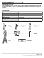
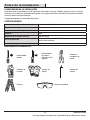
TOOLS REQUIRED
Phillips
screwdriver
1/8 in. Flathead
screwdriver
Wire strippers/
cutters
Circuit tester Work gloves
Silicone
sealant
Ladder Safety goggles

4
Pre-Installation (continued)
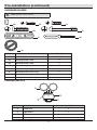
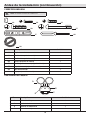
HARDWARE INCLUDED
NOTE: Hardware shown to actual size.
AA BB CC
DD EE
FRONT
FF GG
HH
Part Description Quantity
AA Rubber plug 1
BB Mounting bracket screw 2
CC Mounting bracket screw 2
DD Small mounting bolt 1
EE Large mounting bolt (pre-installed) 1
FF Mounting bracket (not to scale) 1
GG Mini screwdriver 1
HH Gasket (not to scale) 1
PACKAGE CONTENTS
Part Description Quantity
A Lamp head 2
B Light xture 1
C Motion sensor 1
D Mounting plate 1
A
D
B
C

5 HOMEDEPOT.COM
Please contact 1-866-308-3976 for further assistance.
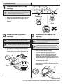
Installation
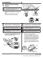
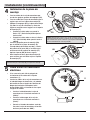
1
Determining the mounting
location
NOTE: The light xture should be mounted approximately
8 ft. (2.4 m) above the ground. If the light xture is
mounted higher than recommended, aiming the sensor
down will reduce the coverage area.
□ Determine the mounting location – wall or eave
mount.
□ Position the lamp heads (A) in the general
direction of the desired light coverage.
Wall Mount
Eave Mount
2
Removing the mounting plate
NOTE: This xture comes with a mounting plate (D). It is
pre-assembled on the light xture (B) for shipping.
NOTE: The large mounting bolt (EE) is pre-installed in
the light xture (B). Do not attempt to remove the large
mounting bolt (EE).
□ Unscrew the large mounting bolt (EE) connecting
the light xture (B) to the mounting plate (D) and
remove the mounting plate (D).
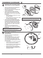
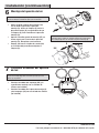
3
Installing the mounting bracket
WARNING: Turn the power off at the circuit breaker or
fuse. Place tape over the circuit breaker switch and verify
power is off at the light xture.
NOTE: Four mounting bracket screws of various sizes are
included. The installation will only require two. Discard the
unused mounting bracket screws after installation.
□ Remove the existing light xture.
□ Install the mounting bracket (FF) with the
stamped word “FRONT” facing away from
the junction box. Use the mounting bracket
screws(BB or CC) that best t the junction
box. If necessary, use the screws that were
removed from the existing light xture.
□ Firmly pull on the mounting bracket (FF) to
verify it is securely mounted to the junction
box.
FRON T
FRONT
A
BB or CC
FF
D
B
EE

6
D
HH
D
DD
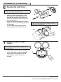
Installation (continued)
4
Installing the mounting plate
□ Route the junction box wires through one of
the large holes in the gasket (HH).
□ Route the junction box wires through the hole
in the mounting plate (D).
□ Place the gasket (HH) and the mounting
plate(D) against the junction box and align
the center holes with the hole in the mounting
bracket (FF).
□ When mounting to a wall, the “UP” arrow
must point upward.
□ When mounting to an eave, the “UP” arrow
must point toward the building.
□ Insert the small mounting bolt (DD) through
the mounting plate (D) hole located below the
threaded hole and through the gasket (HH)
hole, and thread it into the center hole of the
mounting bracket (FF). Tighten the bolt (DD)
securely.
□ Firmly pull on the mounting plate (D) to
verify it is securely attached to the mounting
bracket(FF).
NOTICE: Ensure the gasket (HH) is wrinkle-free and centered
between the mounting plate (D) and the mounting surface.
FRONT
N (White/
Blanc/Blanco)
GND
Terre
Tierra
UP/Haut/Arriba
L (Black/
Noir/Negro)
FRONT
N (White/
Blanc/Blanco)
GND
Terre
Tierra
UP/Haut/Arriba
L (Black/
Noir/Negro)
NOTICE: When attaching this light to an external, surface mount
junction box, ensure the gasket (HH) is centered on the junction box
and the mounting plate (D) presses against the gasket (HH) evenly.
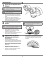
5
Making the electrical
connections
□ If necessary, strip 3/8" of insulation from
junction box wires (1).
□ Insert the junction box wires into the side of
the terminal block and around the ground
screw. Tighten terminal block screws using
the mini-screwdriver (GG) and ground screw to
secure the wires.
□ Insert the white wire from the junction box
into the terminal marked “N (White)”.
□ Insert the black wire from the junction box
into the terminal marked “L (Black)”.
□ Connect the bare or green ground wire
from the junction box to the ground screw
(marked with “GND”).
N (White/
Blanc/Blanco)
GND
Terre
Tierra
UP/Haut/Arriba
L (Black/
Noir/Negro)
3/8"
FF
HH
D
HH
1

7 HOMEDEPOT.COM
Please contact 1-866-308-3976 for further assistance.
Installation (continued)
6
Mounting the light fixture
NOTICE: The two pins on the rear of the light xture must be
inserted into the terminal block for the light to work.
□ Align the top edge of the light xture (B) with
the top edge of the mounting plate(D). Tilt the
light xture (B) toward the mounting plate (D),
making sure the light xture (B) is centered on
the mounting plate (D).
□ Tighten the large mounting bolt (EE) securely
through the center of the mounting plate(D). Do
not overtighten.
□ Push the rubber plug (AA) rmly into the
mounting bolt hole on the light xture (B).
NOTICE: When attaching this light to an external, surface mount
junction box, caulk around the inside of the light xture (B) before
attaching to the mounting plate (D).
7
Caulking around the light
fixture
IMPORTANT: Failure to completely caulk around the gasket (HH)
and the mounting plate (D) could lead to water damage and is not
covered under warranty.
□ Caulk around the gasket (HH) and mounting
surface with silicone sealant (not included).
□ Caulk around the mounting plate (D) and
gasket (HH) with silicone sealant (not
included).
D
D
B
B
D
AA
HH
HH

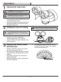
8
Operation
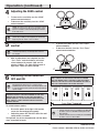
1
Adjusting the lamp heads
WARNING: Risk of re. Keep the lamp heads at least
2in. (51mm) from combustible materials.
CAUTION: Keep lamp heads 30° below horizontal to
avoid water damage and electrical shock.
□ Turn the power on at the circuit breaker or fuse
and turn on the wall switch.
□ If needed, gently grasp the lamp heads (A) and
tilt them up or down or side to side to adjust
the light coverage area.
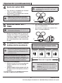
2
Setting the sensor for testing
NOTE: When the “Test / Timer” control is set to the “Test”
position, the light xture will operate during the day or
night. The light will stay on for 8 seconds after all motion
is stopped.
□ Turn the “Test / Timer” control fully
counterclockwise to the “Test” position.
□ Turn the “SENS” control fully clockwise to the
minimum position.
NOTE: The motion sensor will need to completely warm
up (60 seconds) before beginning the setup process.
Te st 10Min
SENS
+–
3
Adjusting the motion sensor
detection zone
□ Perform a “walk test”: walk in an arc across
the front of the motion sensor (C).
□ Watch the light. The light will come on and the
red LED will ash indicating motion has been
detected.
□ Stop, wait for the light to turn off, and then
begin walking again.
□ Continue this process until the detection zone
has been established.
□ If needed, gently grasp the motion sensor (C)
and move it from side to side or up and down
to adjust the detection zone.
C
C
A

9 HOMEDEPOT.COM
Please contact 1-866-308-3976 for further assistance.
Operation (continued)
4
Adjusting the SENS control
□ To increase the sensitivity, turn the “SENS”
control counterclockwise.
□ To decrease the sensitivity, turn the “SENS”
control clockwise.
NOTE: The motion sensor (C) is more sensitive to motion
moving across the front of the sensor. The motion sensor
(C) is less sensitive to motion moving directly toward the
front of the sensor.
NOTE: The higher the “SENS” setting (sensitivity), the
greater the possibility of false triggering. To reduce false
triggering, turn the “SENS” control clockwise.
Te st 10Min
+–
SENS
5
Adjusting the TEST / TIMER
control
NOTE: The “Test / Timer” control determines the amount
of time the light will stay on full bright after all motion
has stopped.
□ After all adjustments are complete, turn the
“Test / Timer” control clockwise and select
a time between 10 seconds (10S) and 10
minutes (10Mins). The light will only work at
night after a time has been selected.
□ To increase the time, turn the “Test / Timer”
control clockwise.
□ To decrease the time, turn the “Test / Timer”
control counterclockwise.
Te st 10Min
+–
SENS
6
Switching motion detection
OFF and ON
NOTE: This light xture can operate as a motion detection
light (default from the factory) or as a dusk-to-dawn
(nighttime) light. The wall switch controlling the light is used
to select the desired mode. In either mode, the light will only
operate at night.
IMPORTANT: THIS LIGHT FIXTURE MUST BE WIRED
THROUGH A WALL SWITCH IN ORDER TO USE THE
MOTION OFF FEATURE. IF THE LIGHT FIXTURE IS
WIRED DIRECTLY TO THE HOUSE WIRING WITH NO
WALL SWITCH, THEN THE MOTION OFF FEATURE
CANNOT BE SET.
To switch between modes:
□ Ensure the power to the light is ON and the
sensor has warmed up (60 seconds).
□ Switch the power OFF–ON–OFF–ON at the wall
switch within 3 seconds.
The light will stay in the selected mode until the above
steps are performed again.
IMPORTANT: IF THERE IS A POWER OUTAGE OR THE
WALL SWITCH TO THE LIGHT FIXTURE IS TURNED
OFF FOR MORE THAN 5 SECONDS, THE LIGHT WILL
DEFAULT TO THE LAST SELECTED MODE SETTING IT
WAS SET TO BEFORE THE POWER OUTAGE.
OFF OFFON ON
Less than 3 seconds
NOTE:
• If motion detection mode is set to ON, the red LED behind
the motion sensor lens will blink indicating motion has
been detected.
• If motion detection mode is set to OFF, the red LED behind
the motion sensor lens will not blink.
C
C

10
Care and Cleaning
□ To prolong the original appearance, clean the light xture with clear water and a soft, damp cloth only.
□ Do not use paints, solvents, or other chemicals on this light xture. They could cause a premature
deterioration of the nish. This is not a defect in the nish and will not be covered by the warranty.
□ Do not spray the light xture with a hose or power washer.
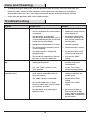
Troubleshooting
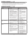
Problem Possible Cause Solution
The light will not come on. □ The light switch is turned off. □ Turn the light switch on.
□ The fuse is blown or the circuit breaker
is turned off.
□ Replace the fuse or turn the
circuit breaker on.
□ The light xture is not properly
attached to the mounting plate, if this is
a new installation (the pins are not fully
seated in the terminal block).
□ Re-install the light xture
to the base and ensure the
pins are fully seated in the
terminal block.
□ Daylight turn-off (photocell) is in effect. □ Recheck after dark.
□ The circuit wiring is incorrect (if this is
a new installation).
□ Verify the wiring is correct.
□ The motion sensor is aimed in the
wrong direction.
□ Re-aim the motion sensor
to cover the desired area.
□ The outside air temperature is close to
the same as a person’s body heat.
□ Increase the “SENS”
setting.
The light comes on during the
day.
□ The motion sensor may be installed in a
relatively dark location.
□ The light xture is operating
normally under these
circumstances.
□ The “Test / Timer” control is in the
“Test” position.
□ Set the “Test / Timer”
control to a timed setting.
The light comes on for no
apparent reason.
□ The motion sensor may be sensing
small animals, automobile trafc, or
other heat sources.
□ Decrease the “SENS”
setting or reposition the
motion sensor.
□ The “SENS” control is set too high. □ Decrease the “SENS”
setting.
□ The outside temperature is much
warmer or cooler than a person’s body
heat (summer or winter).
□ Decrease the “SENS”
setting.
□ The light xture is wired through a
dimmer or timer.
□ Do not use a dimmer or
timer to control the light
xture. Replace the dimmer
or timer with a standard on/
off wall switch.

11 HOMEDEPOT.COM
Please contact 1-866-308-3976 for further assistance.
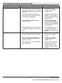
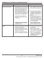
Troubleshooting (continued)
Problem Possible Cause Solution
The lights stay on continuously. □ The motion sensor may be picking up a
heat source, such as an air vent, dryer
vent, or brightly painted, heat-reective
surface.
□ Decrease the “SENS”
setting or reposition the
motion sensor.
□ The motion sensor is in motion off
mode (the red LED behind the motion
sensor lens is not blinking).
□ Switch the motion sensor to
motion on. See Switching
motion detection OFF and
ON on page 9.
□ The light xture is wired through a
dimmer or timer.
□ Do not use a dimmer or
timer to control the light
xture. Replace the dimmer
or timer with a standard on/
off wall switch.
□ The light xture is on the same circuit
as a motor, transformer, or uorescent
bulb.
□ Install the light xture on
a circuit without motors,
transformers, or uorescent
bulbs.
The lights ash on and off. □ Heat or light from the bulbs may be
turning the motion sensor on and off.
□ Reposition the lamp heads
away from the motion
sensor.
□ Heat is being reected from other
objects and may be turning the motion
sensor on and off.
□ Decrease the “SENS”
setting or reposition the
motion sensor.
□ The motion sensor is in “TEST” mode
and warming up.
□ While in “TEST” mode, the
light only stays on for 8
seconds. Set the “Test /
Timer” control to a timed
setting.

Questions, problems, missing parts?
Before returning to the store, call Deant Customer Service
8 a.m.-7 p.m., EST, Monday-Friday, 9 a.m. - 6 p.m., EST, Saturday
1-866-308-3976
HOMEDEPOT.COM
Retain this manual for future use.
208986-01A

GRACIAS
Agradecemos la fe y la conanza que usted ha depositado en Deant al comprar esta luz de seguridad por
movimiento. Procuramos crear continuamente productos de calidad diseñados para mejorar su hogar. Visítenos en
internet para ver nuestra línea completa de productos disponibles que necesita para el mejoramiento de su hogar.
¡Gracias por escoger Deant!
GUÍA PARA EL USO Y CUIDADO
LUZ DE SEGURIDAD POR MOVIMIENTO
¿Tiene preguntas, problemas o piezas faltantes?
Antes de devolverlo a la tienda, llame a Servicio al Cliente de Deant
de 08 a.m.-7 p.m., EST, Lunes - Viernes, 09 a.m.-6 p.m., EST, sábado.
1-866-308-3976
HOMEDEPOT.COM
Articulo #1002366429
1002366591
Modelo #DFI-5852-BK
DFI-5852-WH

14
Contenido
Contenido ................................................14
Información de seguridad ......................14
Garantía...................................................14
5 años de garantía limitada .................14
Antes de la instalación ...........................15
Planicación de la Instalación .............15
Especicaciones ..................................15
Herramientas Requeridas ....................15
Ferretería Incluida ................................16
Contenido del Paquete .........................16
Instalación ..............................................17
Operación ................................................20
Cuidado y limpieza .................................22
Análisis de averías .................................22
Información de seguridad
PRECAUCIONES
□ Por favor lea y entienda todo este manual antes de
tratar de ensamblar, instalar u operar este aparato
de luz.
□ Esta lámpara requiere una fuente de alimentación
de 120 voltios de CA.
□ Algunos códigos exigen que la instalación la realice
un electricista calicado.
□ Este aparato de luz debe estar correctamente
conectado a tierra.
□ Esta lámpara debe ser instalada fuera de casa
sobre una pared o aleros.
□ Esta lámpara debe ser instalada aproximadamente
a 8 pies (2,4 m) por encima del suelo. Si se la
instala a una altura más alta de la recomendada, se
reducirá la zona de cobertura si apunta el detector
hacia abajo.
ADVERTENCIA: Desconecte la energía eléctrica en el
disyuntor o en el fusible. Coloque cinta aislante sobre el
interruptor disyuntor y compruebe que no haya energía
eléctrica en el aparato de luz.
ADVERTENCIA: Riesgo de incendio. Mantenga los
cabezales de la lámpara por lo menos a 2 pulgadas (51
mm) de materiales combustibles.
PRECAUCIÓN: Peligro de quemaduras. Deje que el
aparato de luz se enfríe antes de tocarlo.
AVISO: No conecte este aparato de luz a un interruptor reductor de
luz ni a un temporizador.
□ Este aparato cumple con la Parte 15 de las
Reglas de la FCC. La operación está sujeta a las
dos siguientes condiciones: (1) este aparato no
puede causar interferencias perjudiciales y (2)
este aparato debe aceptar cualquier interferencia
recibida, incluyendo una interferencia que pueda
causar un funcionamiento indeseado.
□ CAN ICES-005 (B)/NMB-005 (B)
Garantía
5 AÑOS DE GARANTÍA LIMITADA
LO QUE SE CUBRE
Se garantiza que este producto no tiene partes defectuosas de fábrica o de mano de obra por un período de 5 años
desde la fecha de compra. Se necesita el recibo de compra para todos los reclamos de garantía.
LO QUE NO SE CUBRE
Esta garantía no incluye el servicio de reparación, ajuste y calibración debido al mal uso, abuso o negligencia, o
LEDs. Los servicios no autorizados o las modicaciones hechas al producto o a cualquier componente invalidarán
esta garantía en su totalidad. Esta garantía no incluye reembolso por inconveniencia, instalación, tiempo de
instalación, perdida de uso, servicio no autorizado, o gastos de envío. Esta garantía no se extiende a otros equipos o
componentes que el consumidor usa junto con este producto.
No hay piezas de servicio disponibles para este producto.
Póngase en contacto con el personal de servicio al cliente al 1-866-308-3976 o visite el sitio www.homedepot.com.

15 HOMEDEPOT.COM
Por favor, póngase en contacto al 1-866-308-3976 para obtener más ayuda.
Antes de la instalación
PLANIFICACIÓN DE LA INSTALACIÓN
Antes de instalar el aparato de luz, esté seguro que estén todas las piezas. Compare las piezas con la Ferretería
incluida y las secciones de Contenidos del paquete. Si cualquier pieza falta o está dañada, no intente ensamblar,
instalar ni operar este aparato de luz.
Tiempo estimado para la instalación: 30 minutos
ESPECIFICACIONES
Alcance
Hasta 40 pies (12,2 m) (Varía con la temperatura circundante)
Ángulo de detección
Hasta 180°
Carga eléctrica - LED Integrado
19 Vatios
Lúmenes
1250
Requisitos de la energía eléctrica
120 VCA, 60 Hz
Fases de operación
Prueba, Movimiento ENCENDIDO (ON), Movimiento APAGADO (OFF),
Manual (solo nocturna)
Retardo de tiempo
Regulable - 10 segundos a 10 minutos
HERRAMIENTAS REQUERIDAS
Destornillador
phillips
Destornillador
de cabeza
plana de 1/8 de
pulgada
Peladores/
cortadores de
cables
Probador de
circuitos
Guantes de
trabajo
Sellador de
silicona
Escalera Gafas de seguridad

16
Antes de la instalación (continuación)
FERRETERÍA INCLUIDA
NOTA: La ferretería se muestra en su tamaño real
AA BB CC
DD EE
FRONT
FF GG
HH
Pieza Descripción Cantidad
AA Tapón de caucho 1
BB Tornillo del soporte de montaje 2
CC Tornillo del soporte de montaje 2
DD Tornillo pequeño de montaje 1
EE Tornillo grande de montaje (pre-instalado) 1
FF Soporte de montaje (no está a escala) 1
GG Mini-destornillador 1
HH Empaque (no está a escala) 1
CONTENIDO DEL PAQUETE
Pieza Descripción Cantidad
A Cabezal de lámpara 2
B Artefacto de luz 1
C Detector de movimiento 1
D Placa de montaje 1
D
B
C
A

17 HOMEDEPOT.COM
Por favor, póngase en contacto al 1-866-308-3976 para obtener más ayuda.
Instalación
1
Determinación del sitio de
montaje
NOTA: Esta lámpara debe ser instalada aproximadamente
a 8 pies (2,4 m) por encima del suelo. Si se la instala a una
altura más alta de la recomendada, se reducirá la zona de
cobertura si apunta el detector hacia abajo.
□ Determine el sitio de montaje – pared o alero.
□ Coloque los cabezales de la lámpara (A) en
la dirección general de la cobertura de luz
deseada.
Montaje en
pared
Montaje en
alero
2
Remoción de la placa de
montaje
NOTA: El aparato viene con una placa de montaje (D).
Está premontado en la lámpara (B) para ser enviado.
NOTA: El tornillo de jación grande (EE) está pre-
instalado en la lámpara (B). No trate de quitar el tornillo
grande de montaje (EE).
□ Desenrosque el tornillo grande de montaje
(EE) que conecta la lámpara (B) a la placa de
montaje (D) y retire la placa de montaje (D).
3
Instalación del soporte de
montaje
ADVERTENCIA: Desconecte la energía eléctrica en el
disyuntor o en el fusible. Coloque cinta aislante sobre el
interruptor disyuntor y compruebe que no haya energía
eléctrica en el aparato de luz.
NOTA: Se incluyen cuatro tornillos de varios tamaños
para el soporte de montaje. La instalación sólo requiere
dos. Deseche los tornillos del soporte de montaje no
utilizados luego de la instalación.
□ Retire el aparato de luz existente.
□ Instale el soporte de montaje (FF) con la
palabra estampada “FRENTE” en dirección
contraria a la caja de conexiones. Use los
tornillos del soporte de montaje (BB o CC) que
mejor encajen con la caja de conexiones. Si es
necesario, use los tornillos que fueron retirados
del aparato de luz anterior.
□ Hale con rmeza el soporte de montaje (FF)
para vericar que esté bien montado en la caja
de conexiones.
FRON T
FRONT
BB o CC
FF
A
D
B
EE

18
Instalación (continuación)
4
Instalación de la placa de
montaje
□ Pase los cables de la caja de conexiones por
uno de los agujeros grandes del empaque (HH).
□ Pase los cables de la caja de conexiones por el
agujero que está en la placa de montaje (D).
□ Coloque el empaque (HH) y la placa de montaje
(D) sobre la caja de conexiones y alinee los
agujeros centrales con el agujero en el soporte
de montaje (FF).
□ Cuando la instale sobre una pared, la
echa “UP” (Hacia Arriba) debe apuntar
hacia arriba.
□ Cuando la instale sobre un alero, la echa
“UP” (Hacia Arriba) debe apuntar hacia el
edicio.
□ Inserte el pequeño perno de montaje (DD)
por el oricio de la placa de montaje (D)
situado debajo del oricio roscado y a través
del oricio de la junta (HH), e insértelo en el
oricio central del soporte de montaje (FF).
Apriete el perno (DD) de forma segura.
□ Hale rmemente de la placa de montaje (D)
para vericar que esté bien sujeta al soporte
de montaje (FF).
AVISO: Asegúrese de que el empaque (HH) no tenga arrugas y esté
centrado entre la placa de montaje (D) y la supercie de montaje.
FRONT
N (White/
Blanc/Blanco)
GND
Terre
Tierra
UP/Haut/Arriba
L (Black/
Noir/Negro)
FRONT
N (White/
Blanc/Blanco)
GND
Terre
Tierra
UP/Haut/Arriba
L (Black/
Noir/Negro)
AVISO: Cuando sujete esta luz a una caja de conexiones externa
y montada sobre una supercie asegúrese de que el empaque (HH)
esté centrado en la caja de conexiones y que la placa de montaje (D)
presione uniformemente contra la junta (HH).
5
Cómo hacer las conexiones
eléctricas
□ Si es necesario, pele 3/8 de pulgada de
aislamiento de los cables de la caja de
conexiones (1).
□ Inserte los cables de la caja de conexiones en
el lado del bloque de terminales y al rededor
del tornillo de tierra. Apriete los tornillos del
bloque de terminales utilizando el mini-
destornillador (GG) y el tornillo de tierra para
asegurar los cables.
□ Inserte el cable blanco de la caja de
conexiones en el terminal marcado “N
(White)”.
□ Inserte el cable negro de la caja de
conexiones en el terminal marcado “L
(Black)”.
□ Conecte el alambre desnudo o verde de
tierra de la caja de conexiones al tornillo
de tierra (marcado con “GND”).
N (White/
Blanc/Blanco)
GND
Terre
Tierra
UP/Haut/Arriba
L (Black/
Noir/Negro)
3/8"
D
HH
D
DD
FF
HH
D
HH
1

19 HOMEDEPOT.COM
Por favor, póngase en contacto al 1-866-308-3976 para obtener más ayuda.
Instalación (continuación)
6
Montaje del aparato de luz
AVISO: Las dos clavijas de la parte posterior de la lámpara se deben
insertar en el bloque de terminales para que la luz funcione.
□ Alinee el borde superior de la lámpara(B)
con el borde superior de la placa de
montaje(D). Incline la lámpara (B) hacia la
placa de montaje (D), asegurándose de que
la lámpara(B) esté centrada en la placa de
montaje (D).
□ Apriete el tornillo grande de montaje (EE) en
forma segura por el centro de la placa de
montaje (D). No apriete excesivamente.
□ Empuje con fuerza el tapón de caucho (AA)
en el oricio del perno de montaje de la
lámpara(B).
AVISO: Cuando conecte esta luz a una caja de conexiones externa,
montada sobre la supercie, calafatee alrededor de la parte interna
de la lámpara (B) antes de conectarla a la placa de montaje (D).
7
Calafatee alrededor del aparato
de luz
IMPORTANTE: Si no se calafatea por completo el empaque (HH)
y la placa de montaje (D) podría causar daño por agua y no está
cubierto por la garantía.
□ Calafatee alrededor del empaque (HH) y la
supercie de montaje con un sellador de
silicona (no incluido).
□ Calafatee alrededor de la placa de montaje (D)
y del empaque (HH) con un sellador de silicona
(no incluido).
D
B
B
AA
D
D
HH
HH

20
Operación
1
Ajuste de los cabezales de la
lámpara
ADVERTENCIA: Riesgo de incendio. Mantenga los
cabezales de la lámpara por lo menos a 2 pulgadas (51
mm) de materiales combustibles.
PRECAUCIÓN: Mantenga los cabezales de la lámpara
30° debajo de la línea horizontal para evitar daños por
agua y descargas eléctricas.
□ Conecte la energía eléctrica en el disyuntor
o en el fusible y encienda el interruptor de la
pared.
□ Si es necesario, sujete suavemente los
cabezales de la lámpara (A) e inclínelos hacia
arriba o hacia abajo o de lado a lado para
ajustar el área de cobertura de la luz.
2
Calibración del detector para
prueba
NOTA: Cuando el control Test / Timer está programado
a la posición “Prueba”, la lámpara funcionará durante el
día o la noche. La luz permanecerá encendida 8 segundos
después que todo movimiento se ha detenido.
□ Gire el control “Test / Timer” (“Prueba /
Temporizador”) por completo en sentido
antihorario a la posición “Test”.
□ Gire el control “SENS” completamente hacia la
derecha hasta la posición mínima.
NOTA: El detector de movimiento necesitará calentarse
completamente (60 segundos) antes de empezar el
proceso de puesta a punto.
Te st 10Min
SENS
+–
3
Regulación de la zona de
detección del detector de
movimiento
□ Haga una “prueba caminando”: camine
transversalmente a la parte frontal del detector de
movimiento (C) siguiendo la trayectoria de un arco.
□ Observe la luz. La luz se encenderá y el LED
rojo destellará indicando que se ha detectado
movimiento.
□ Deténgase, espere que la luz se apague, y
luego empiece a caminar de nuevo.
□ Continúe este proceso hasta que la zona de
detección haya sido establecida.
□ Si es necesario, sujete suavemente el detector
de movimiento (C) y muévalo de lado a lado o
de arriba hacia abajo para ajustar la zona de
detección.
C
C
A

21 HOMEDEPOT.COM
Por favor, póngase en contacto al 1-866-308-3976 para obtener más ayuda.
Operación (continuación)
4
Ajuste del control SENS
□ Para aumentar la sensibilidad, gire el control
“SENS” en sentido antihorario.
□ Para disminuir la sensibilidad, gire el control
“SENS” en sentido horario.
NOTA: El detector de movimiento (C) es más sensible al
movimiento transversal a la parte frontal del detector. El
detector de movimiento (C) es menos sensible al movimiento
que se dirige directamente hacia la parte frontal del detector.
NOTA: Mientras mayor sea la calibración del “SENS”
(sensibilidad), mayor será la posibilidad de falsas alarmas.
Para reducir las falsas alarmas, gire el control “SENS”
hacia la derecha.
Te st 10Min
+–
SENS
5
Ajuste del control TEST /
TIMER
NOTA: El control “Test / Timer” determina la cantidad de
tiempo que la luz permanecerá encendida después de que
todo movimiento se haya detenido.
□ Después de completar todos los ajustes, gire
el control “Test / Timer” en sentido horario y
seleccione un tiempo entre 10 segundos (10S)
y 10 minutos (10Min). La luz sólo funcionará
por la noche después de haber seleccionado
una hora.
□ Para aumentar el tiempo, gire el control “Test /
Timer” en sentido horario.
□ Para disminuir el tiempo, gire el control “Test /
Timer” en sentido antihorario.
Te st 10Min
+–
SENS
6
ACTIVANDO y DESACTIVANDO
la detección de movimiento
NOTA: Esta lámpara puede funcionar como luz de
detección de movimiento (programado en fábrica) o como
luz del anochecer a amanecer (nocturna). El interruptor
de pared que controla la luz se utiliza para seleccionar la
modalidad deseada. En cualquier modalidad la luz sólo
funcionará por la noche.
IMPORTANTE: ESTA LÁMPARA DEBE SER CONECTADA A TRAVÉS
DE UN INTERRUPTOR DE PARED PARA QUE SE PUEDA USAR LA
FUNCIÓN DE DESACTIVACIÓN DE DETECCIÓN DE MOVIMIENTO. SI LA
LÁMPARA ESTÁ CABLEADA DIRECTAMENTE AL CABLEADO DE LA CASA
SIN UN INTERRUPTOR DE PARED, ENTONCES NO SE PODRÁ FIJAR LA
FUNCIÓN DE DESACTIVACIÓN DE DETECCIÓN DE MOVIMIENTO.
Para cambiar entre modalidades:
□ Asegúrese de que la luz está encendida (ON)
y de que el detector se ha calentado (60
segundos).
□ PRENDA-APAGUE-PRENDA-APAGUE (OFF-ON-
OFF-ON) usando el interruptor de pared en 3
segundos.
La luz permanecerá en la modalidad seleccionada
hasta que se repitan los pasos anteriores.
IMPORTANTE: SI HAY UN APAGÓN O SI EL INTERRUPTOR DE PARED
DE LA LÁMPARA ESTA DESCONECTADO POR MÁS DE 5 SEGUNDOS,
LA LUZ REGRESARÁ AL ÚLTIMO AJUSTE ESCOGIDO AL QUE ESTUVO
PROGRAMADO ANTES DEL APAGÓN.
APAGADO APAGADOENCENDIDO ENCENDIDO
Menos de 3 segundos
NOTA:
• Si se ja la modalidad de detección de movimiento
en ON, el LED rojo detrás de la lente del detector de
movimiento parpadeará indicando que se ha detectado
movimiento.
• Si se ja la modalidad de detección de movimiento
en OFF, el LED rojo detrás de la lente del detector de
movimiento no parpadeará.
C
C

22
Cuidado y limpieza
□ Para prolongar la apariencia original, limpie la lámpara solo con agua limpia y un paño suave y húmedo.
□ No use pinturas, solventes ni otros químicos en este aparato de luz. Podrían ser la causa de una prematura
deterioración del acabado. Esto no es un defecto del acabado y no será cubierto por la garantía.
□ No rocíe la lámpara con una manguera o lavadora a presión.
Análisis de averías
Problema Causa Probable Solución
La luz no se enciende. □ El interruptor de la luz está apagado. □ Encienda el interruptor de la luz.
□ El fusible está quemado o el disyuntor
está desconectado.
□ Cambie el fusible o conecte el
disyuntor.
□ La lámpara no está correctamente
sujetada a la placa de montaje, si se
trata de una nueva instalación (las
clavijas no están asentadas por com-
pleto en el bloque de terminales).
□ Vuelva a instalar la lámpara
en la base y asegúrese de que
las clavijas estén asentadas
por completo en el bloque de
terminales.
□ El apagado de la luz diurna (fotocélu-
la) está vigente.
□ Vuelva a revisar al amanecer.
□ El cableado del circuito es incorrecto
(si esta es una instalación nueva).
□ Verique que el cableado esté
correcto.
□ El detector de movimiento está enfo-
cando a la dirección incorrecta.
□ Vuelva a enfocar el detector de
movimiento para que cubra el
área deseada.
□ La temperatura del aire exterior está cer-
cana al calor corporal de una persona.
□ Aumente la calibración del
alcance (“SENS”).
La luz se enciende durante
el día.
□ El detector de movimiento puede estar
instalado en un sitio relativamente oscuro.
□ El aparato de luz está operando
normalmente bajo estas
circunstancias.
□ El control “Test / Timer” está en la
posición “Test”.
□ Fije el control “Test / Timer” a
un ajuste programado.
La luz se enciende sin razón
aparente.
□ El detector de movimiento puede
estar detectando animales pequeños,
tráco de automóviles u otras fuentes
de calor.
□ Reduzca la calibración del
alcance (“SENS”) o vuelva a co-
locar el detector de movimiento.
□ El control “SENS” está calibrado
demasiado alto.
□ Reduzca la calibración del
alcance (“SENS”).
□ La temperatura exterior está más ca-
liente o más fría que el calor corporal
de una persona (verano o invierno).
□ Reduzca la calibración del
alcance (“SENS”).
□ El aparato de luz está cableado a
través de un reductor de luz o de un
temporizador.
□ No use un reductor de luz o un
temporizador para controlar el
aparato de luz. Cambie el reductor
de luz o el temporizador por un
interruptor de pared estándar de
encendido/apagado.

23 HOMEDEPOT.COM
Por favor, póngase en contacto al 1-866-308-3976 para obtener más ayuda.
Problema Causa Probable Solución
Las luces permanecen en-
cendidas constantemente.
□ El detector de movimiento puede estar
absorbiendo calor de una fuente de calor
como una ventosa de aire, una secadora
de aire, o una supercie pintada con
colores brillantes y que reeja el calor.
□ Reduzca la calibración del
alcance (“SENS”) o vuelva a co-
locar el detector de movimiento.
□ El detector de movimiento está en
“OFF” (modalidad de apagado) (el LED
rojo detrás de la lente del detector de
movimiento no está parpadeando).
□ Ponga el detector de movimien-
to a detectar movimiento. Vea
ACTIVANDO y DESACTIVANDO la
detección de movimiento en la
página 21.
□ El aparato de luz está cableado a
través de un reductor de luz o de un
temporizador.
□ No use un reductor de luz o un
temporizador para controlar el
aparato de luz. Cambie el reduc-
tor de luz o el temporizador por
un interruptor de pared estándar
de encendido/apagado.
□ El aparato de luz está en el mismo
circuito que un motor, transformador
o tubo uorescente.
□ Instale el aparato de luz en un
circuito sin motores, transfor-
madores o tubos uorescentes.
Las luces se encienden y se
apagan.
□ El calor o la luz de las bombillas
puede estar encendiendo y apagando
al detector de movimiento.
□ Vuelva a colocar los cabezales
de la lámpara lejos del detector
de movimiento.
□ El calor reejado desde otro objeto
puede estar encendiendo y apagando
al detector de movimiento.
□ Reduzca la calibración del
alcance (“SENS”) o vuelva a co-
locar el detector de movimiento.
□ El detector de movimiento está en la
fase “TEST” (PRUEBA) y calentándose.
□ Mientras está en la modalidad
“TEST”, la luz sólo permanece
encendida por 8 segundos. Fije
el control “Test / Timer” a un
ajuste programado.
Análisis de averías (continuación)

¿Tiene preguntas, problemas o piezas faltantes?
Antes de devolverlo a la tienda, llame a Servicio al Cliente de Deant
de 08 a.m.-7 p.m., EST, Lunes - Viernes, 09 a.m.-6 p.m., EST, sábado.
1-866-308-3976
HOMEDEPOT.COM
Guarde este manual para uso futuro.
208986-01A
-
 1
1
-
 2
2
-
 3
3
-
 4
4
-
 5
5
-
 6
6
-
 7
7
-
 8
8
-
 9
9
-
 10
10
-
 11
11
-
 12
12
-
 13
13
-
 14
14
-
 15
15
-
 16
16
-
 17
17
-
 18
18
-
 19
19
-
 20
20
-
 21
21
-
 22
22
-
 23
23
-
 24
24


Defiant DFI-5852-WH Instrucciones de operación
- Tipo
- Instrucciones de operación
- Este manual también es adecuado para
en otros idiomas
Artículos relacionados
-
Defiant DFI-5998-BK Instrucciones de operación
-
-
-
-
-
-
-
-
-
Defiant DFI-5408-GR Instrucciones de operación