
OWNER’S MANUAL
MANUAL DE INSTRUCCIONES
Integrated Amplifier
RL

CAUTION: READ THIS BEFORE OPERATING YOUR UNIT.
i En
1 To assure the finest performance, please read this manual
carefully. Keep it in a safe place for future reference.
2 Install this sound system in a well ventilated, cool, dry,
clean place - away from direct sunlight, heat sources,
vibration, dust, moisture, and/or cold. For proper
ventilation, allow the following minimum clearances
around this unit.
Top: 30 cm, Rear: 20 cm, Sides: 20 cm
3 Locate this unit away from other electrical appliances,
motors, or transformers to avoid humming sounds.
4 Do not expose this unit to sudden temperature changes
from cold to hot, and do not locate this unit in an
environment with high humidity (i.e. a room with a
humidifier) to prevent condensation inside this unit,
which may cause an electrical shock, fire, damage to this
unit, and/or personal injury.
5 Avoid installing this unit where foreign object may fall
onto this unit and/or this unit may be exposed to liquid
dripping or splashing. On the top of this unit, do not
place:
– Other components, as they may cause damage and/or
discoloration on the surface of this unit.
– Burning objects (i.e. candles), as they may cause fire,
damage to this unit, and/or personal injury.
– Containers with liquid in them, as they may fall and
liquid may cause electrical shock to the user and/or
damage to this unit.
6 Do not cover this unit with a newspaper, tablecloth,
curtain, etc. in order not to obstruct heat radiation. If the
temperature inside this unit rises, it may cause fire,
damage to this unit, and/or personal injury.
7 Do not plug in this unit to an AC wall outlet until all
connections are complete.
8 Do not operate this unit upside-down. It may overheat,
possibly causing damage.
9 Do not use force on switches, knobs and/or cords.
10 When disconnecting the power cable from the AC wall
outlet, grasp the plug; do not pull the cable.
11 Do not clean this unit with chemical solvents; this might
damage the finish. Use a clean, dry cloth.
12 Only voltage specified on this unit must be used. Using
this unit with a higher voltage than specified is dangerous
and may cause fire, damage to this unit, and/or personal
injury. Yamaha will not be held responsible for any
damage resulting from use of this unit with a voltage
other than specified.
13 VOLTAGE SELECTOR
The VOLTAGE SELECTOR on the rear panel of this
unit must be set for your local main voltage BEFORE
plugging into the AC wall outlet. Voltages are:
.................................... AC 110-120/220-240 V, 50/60 Hz
14 To prevent damage by lightning, keep the power cable
and outdoor antennas disconnected from an AC wall
outlet or this unit during a lightning storm.
15 Do not attempt to modify or fix this unit. Contact
qualified Yamaha service personnel when any service is
needed. The cabinet should never be opened for any
reasons.
16 When not planning to use this unit for long periods of
time (i.e. vacation), disconnect the AC power plug from
the AC wall outlet.
17 Be sure to read the “TROUBLESHOOTING” section on
common operating errors before concluding that this unit
is faulty.
18 Before moving this unit, press A (power) to set this unit
to standby mode, and then disconnect the AC power plug
from the AC wall outlet.
19 Condensation will form when the surrounding
temperature changes suddenly. Disconnect the power
cable from the outlet, then leave this unit alone.
20 When using this unit for a long time, this unit may
become warm. Turn the power off, then leave this unit
alone for cooling.
21 Install this unit near the AC wall outlet and where the AC
power plug can be reached easily.
22 The batteries shall not be exposed to excessive heat such
as sunshine, fire or the like.
23 Excessive sound pressure from earphones and
headphones can cause hearing loss.
This label is required to be attached to a product of which
the temperature of the top cover may be hot during
operation.
CAUTION: READ THIS BEFORE OPERATING YOUR UNIT.
This unit is not disconnected from the AC power source as long as
it is connected to the AC wall outlet, even if this unit itself is turned
off by A. This state is called the standby mode. In this state, this
unit is designed to consume a very small quantity of power.
WARNING
TO REDUCE THE RISK OF FIRE OR ELECTRIC SHOCK, DO
NOT EXPOSE THIS UNIT TO RAIN OR MOISTURE.

1 En
English
USEFUL FEATURES ................................... 1
SUPPLIED ACCESSORIES.........................1
CONTROLS AND FUNCTIONS................. 2
Front panel ........................................................2
Rear panel .........................................................4
Remote control..................................................6
CONNECTIONS............................................ 9
Connecting speakers and source components...9
Connecting power cable..................................10
PLAYBACK................................................. 11
Playing a source ............................................. 11
Adjusting to the desired sound....................... 12
TROUBLESHOOTING.............................. 13
SPECIFICATIONS ..................................... 15
This unit allows you to:
◆ Enjoy the highest sound quality of compact discs by
using the CD direct function (A-S701 only)
(see page 12)
◆ Enjoy pure, high fidelity sound by using the Pure
Direct function (see page 12)
◆ Save power by using AUTO POWER STANDBY
switch (see page 4)
◆ Use the remote control of this unit to operate a Yamaha
tuner and/or CD player (see page 7)
◆ Boost bass sounds by connecting a subwoofer
(see page 9)
Please check that you received all of the following parts.
CONTENTS
About this manual
• y indicates a tip for your operation.
• The illustrations used in this Owner’s Manual are A-S701.
• Depending on the model, there are some countries/regions where it may not be sold.
USEFUL FEATURES
SUPPLIED ACCESSORIES
Remote control Batteries (x2)
(AA, R6, UM-3)
Power cable
(A-S701 only)

2 En
1 A (power) switch
Turns on and off the power of this unit.
Even when this unit is turned off, this unit consumes a small
amount of power.
2 Power indicator
3 Remote control sensor
Receives infrared signals from the remote control.
4 PHONES jack
Connect your headphones.
5 SPEAKERS selector
6 BASS control
Increases or decreases the low frequency response.
The 0 position produces a flat response.
Control range: –10 dB to +10 dB
7 TREBLE control
Increases or decreases the high frequency response.
The 0 position produces a flat response.
Control range: –10 dB to +10 dB
CONTROLS AND FUNCTIONS
Front panel
(A-S701)
Note
Indicator Status
Brightly lit The power of this unit is “on”.
Dimly lit
This unit is in “standby” mode.
For details on the “standby” mode, see
page 6.
Off The power of this unit is “off”.
Selector
position
Speaker status
OFF Both sets of speakers are off.
A or B
The set of speakers connected to the A
or B terminals is on.
A+B BI-WIRING Both sets of speakers are on.

CONTROLS AND FUNCTIONS
3 En
English
8 BALANCE control
Adjusts the sound output balance of the left and right
speakers to compensate for sound imbalances.
If you rotate the BALANCE control to the end of L (left) or
R (right), the opposite side of channel is muted.
9 LOUDNESS control
Retain a full tonal range at any volume level
(see page 12).
0 INPUT selector and indicators
Selects the input source you want to listen to. The
input source indicators light up when the
corresponding input sources are selected.
y
The input source names correspond to the names of the
connection jacks on the rear panel.
A VOLUME control
Increases or decreases the sound output level.
B CD DIRECT AMP button and indicator
(A-S701 only)
Reproduces CD sound in the highest signal quality
(see page 12).
The indicator above it lights up when this function is
turned on.
C PURE DIRECT button and indicator
Reproduces any input source in the purest sound
possible (see page 12).
The indicator above it lights up when this function is
turned on.
(A-S701)
Note

CONTROLS AND FUNCTIONS
4 En
1 CD input jacks
Used to connect a CD player (see page 9).
2 PHONO jacks and GND terminal
Used to connect a turntable that uses an MM cartridge,
and to ground the terminal (see page 9).
3 Audio input/output jacks
Used to connect external components, such as a tuner,
etc (see page 9).
4 DIGITAL (OPTICAL) jack
Used to connect a component with a digital optical
output (see page 9).
5 DIGITAL (COAXIAL) jack
Used to connect a component with a digital coaxial
output (see page 9).
6 DC OUT jack
For supplying power to a Yamaha AV accessory. For
details on connections, refer to the instruction manual
of the AV accessory.
7 SPEAKERS A/B terminals
Used to connect one or two speaker sets (see page 9).
8 SUBWOOFER OUT jack
Used to connect a subwoofer with built-in amplifier
(see page 9).
y
The SUBWOOFER OUT jack attenuates signals over 90 Hz.
9 AUTO POWER STANDBY switch
Rear panel
(A-S701)
(A-S501/S301)
Switch
position
Status
ON
The unit enters standby mode
automatically if not operated for 8
hours.
OFF
The unit does not enter standby mode
automatically.

CONTROLS AND FUNCTIONS
5 En
English
0 VOLTAGE SELECTOR (General model only)
Used to set to your local main voltage (see page 10).
A IMPEDANCE SELECTOR switch
Do not change the IMPEDANCE SELECTOR switch
while the power is turned on, as doing so may damage
the unit.
If the IMPEDANCE SELECTOR switch may not be
fully slid to either position, remove the power cable
and slide the switch all the way to either position.
Select the switch position according to the impedance
of the speakers.
B AC IN (A-S701)
Used to connect the supplied power cable to an AC
wall outlet (see page 10).
Power cable (A-S501/S301)
Used to connect this unit to an AC wall outlet
(see page 10).
(A-S701)
(A-S501/S301)
CAUTION
Speaker
connection
Speaker
impedance
Switch
position
SPEAKERS A
or
SPEAKERS B
6 Ω or higher
(General model)
8 Ω or higher
(Asia model)
HIGH
4 Ω or higher LOW
SPEAKERS A
and
SPEAKERS B
12 Ω or higher
(General model)
16 Ω or higher
(Asia model)
HIGH
8 Ω or higher LOW
Bi-wiring
6 Ω or higher
(General model)
8 Ω or higher
(Asia model)
HIGH
4Ω or higher LOW

CONTROLS AND FUNCTIONS
6 En
1 Infrared signal transmitter
Sends infrared signals.
2 A AMP
Turns this unit on, or sets it to standby mode.
3 OPEN/CLOSE
Opens/closes the disc tray of the Yamaha CD player.
Refer to the owner’s manual of your CD player for
details.
Even when using a Yamaha CD player, certain components
and features may not be available.
4 A CD
Turns the Yamaha CD player on, or sets it to standby
mode. Refer to the owner’s manual of your CD player
for details.
Even when using a Yamaha CD player, certain components
and features may not be available.
5 CD DIRECT AMP (A-S701 only)
Reproduces CD sound in the highest signal quality
(see page 12).
6 Input selector buttons
Selects the input source you want to listen to.
y
The input source names correspond to the names of the
connection jacks on the rear panel.
Remote control
(A-S501/S301)(A-S701)
Note
Note

CONTROLS AND FUNCTIONS
7 En
English
7 VOLUME +/–
Increases or decreases the sound output level.
8 MUTE
Reduces the current volume level by approximately
20 dB. Press again to restore the audio output to the
previous volume level. Pressing the VOLUME +/–
also cancels muting.
The input indicator on the front panel for the current
input source blinks while the output is muted.
9 PURE DIRECT
Reproduces any input source in the purest sound
possible (see page 12).
0 Yamaha tuner control buttons
The following buttons can be used to control various
functions of a Yamaha tuner.
Refer to your component’s owner’s manual for more
information.
BAND
Selects the reception band (FM/AM).
TUNING jj / ii
Selects the tuning frequency.
MEMORY
Stores the current FM/AM station as a preset.
PRESET j / i
Selects a preset FM/AM station.
Even when using a Yamaha tuner, certain components and
features may not be available.
A Yamaha CD player control buttons
The following buttons can be used to control a
Yamaha CD player.
Refer to your component’s owner’s manual for more
information.
w Rewinds playback
f Fast-forwards playback
DISC SKIP Skips to the next disc in a CD changer
(A-S501/S301 only)
e Pauses playback
b Skips backward
a Skips forward
p Starts playback
s Stops playback
Even when using a Yamaha CD player, certain components
and features may not be available.
Note
Note

CONTROLS AND FUNCTIONS
8 En
■ Installing batteries ■ Operation range
Point the remote control at the remote control sensor on
this unit and remain within the operating range shown
below.
■ Notes on remote control and batteries
• The area between the remote control and this unit must be clear of large obstacles.
• Be careful not to spill water or other liquids on the remote control.
• Be careful not to drop the remote control.
• Do not leave or store the remote control in the following conditions:
– places of high humidity, such as near a bathroom
– places of high temperatures, such as near a heater or stove
– places of extremely low temperatures
– dusty places
• Change all batteries if you notice the operation range of the remote control narrows.
• If the batteries run out, immediately remove them from the remote control to prevent an explosion or acid leak.
• If you find leaking batteries, discard the batteries immediately, taking care not to touch the leaked material. If the leaked material
comes into contact with your skin or gets into your eyes or mouth, rinse it away immediately and consult a doctor. Clean the battery
compartment thoroughly before installing new batteries.
• Do not use old batteries together with new ones. This may shorten the life of the new batteries or cause old batteries to leak.
• Do not use different types of batteries (such as alkaline and manganese batteries) together. Batteries that look the same may have a
different specification.
• Dispose of batteries according to your regional regulations.
• Keep the batteries in a location out of reach of children.
Batteries can be dangerous if a child were to put in his or her mouth.
• If you plan not to use this unit for a long period of time, remove the batteries from this unit. Otherwise, the batteries will wear out,
possibly resulting in a leakage of battery liquid that may damage this unit.
AA, R6, UM-3 batteries
Approximately
6 m
Remote control

9 En
English
Make sure to connect L (left) to L, R (right) to R, “+” to “+” and “–” to “–”. If the connections are faulty, no sound will
be heard from the speakers, and if the polarity of the speaker connections is incorrect, the sound will be unnatural and
lack bass. Refer to the owner’s manual for each of your components.
Make sure to use RCA cables or optical cable to connect audio components.
Do not connect this unit or other components to the main power until all connections between components are complete.
Only PCM signals can be input to the DIGITAL (OPTICAL/COAXIAL) jacks of this unit. For details on the supported
PCM signals, see page 15.
y
• The PHONO jacks are designed for connecting a turntable with an MM cartridge.
• Connect your turntable to the GND terminal to reduce noise in the signal. However, for some turntables, you may hear less noise
without the GND connection.
CONNECTIONS
Connecting speakers and source components
CAUTION
CD recorder,
etc.
Tuner
Speakers A
Speakers B
DVD player,
etc.
CD player
Turntable
Audio
out
Audio
out
Audio
In
Audio
out
GND
LeftRight
LeftRight
Audio
out
Audio
out
TV, etc.
Audio
out
SubwooferTape deck,
etc.
BD player, etc.
Audio
out
Audio
out
Audio
In

10 En
CONNECTIONS
■ REC jacks
• The audio signals are not output via the LINE 2 REC
or LINE 3 REC output jacks when LINE 2 or LINE 3
is selected with the INPUT selector.
• The VOLUME, BASS, TREBLE, BALANCE and
LOUDNESS controls and the CD DIRECT function
(or the PURE DIRECT function) have no effect on the
source being recorded.
■ Connecting speaker cables
1 Remove approximately 10 mm of insulation from the
end of each speaker cable.
2 Twist the bare wires of the cable firmly together.
3 Unscrew the knob.
4 Insert one bare wire into the hole in the side of each
terminal.
5 Tighten the knob to secure the wire.
• Set the IMPEDANCE SELECTOR switch according to
the impedance of the speakers to be connected (see
page 5).
• Do not let bare speaker wires touch each other or any
metal part of this unit. This could damage this unit and/
or the speakers.
■ Connecting via banana plug
(North America, General, China and
Australia models only)
1 Tighten the knob.
2 Insert the banana plug into the end of the
corresponding terminal.
■ Bi-wire connection
In the case of speakers supporting the bi-wiring
connection, the tweeter/midrange unit and woofer of the
speakers can be driven independently through connections
shown in the following figure, allowing you to enjoy clear
mid- and high-range sounds.
Connect the other speaker to the other set of terminals in
the same way.
When making bi-wire connections, remove the shorting bridges
or cables on the speaker. Refer to the speakers’ instruction
manuals for more information.
y
To use the bi-wire connections, set the SPEAKERS selector on
the front panel to the A+B BI-WIRING position.
(General model only)
Before connecting the power cable, make sure you set
VOLTAGE SELECTOR of this unit according to your
local voltage. Improper setting of VOLTAGE SELECTOR
may cause fire and damage to this unit.
■ AC IN (A-S701)
Connect the supplied power cable to AC IN after all other
connections are complete.
■ Power cable (A-S501/S301)
Connect the power cable to an AC wall outlet after all
other connections are complete.
CAUTION
Red: positive (+)
Black: negative (–)
10 mm
Banana plug
Note
Connecting power cable
CAUTION
Rear panel
Speaker
To the AC
wall outlet
(A-S701)
To the AC
wall outlet
(A-S501/S301)

11 En
English
1 Rotate the VOLUME control on the front
panel fully counter-clockwise so as not to
play sounds loud suddenly.
2 Press A (power) switch on the front panel
inward to turn on this unit.
3 Rotate the INPUT selector on the front panel
(or press one of the Input selector buttons on
the remote control) to select the input source
you want to listen to.
The indicator for the selected input source lights up.
4 Rotate the SPEAKERS selector on the front
panel to select SPEAKERS A, B or A+B BI-
WIRING.
y
Set the SPEAKERS selector to the A+B BI-WIRING position
when two sets of speakers are connected using bi-wire
connections, or when using two sets of speakers simultaneously
(A and B).
5 Play the selected input source.
6 Rotate the VOLUME control on the front
panel (or press VOLUME +/– on the remote
control) to adjust the sound output level.
y
You can adjust to the desired sound by using the BASS,
TREBLE, BALANCE and LOUDNESS controls, the CD
DIRECT AMP button, or the PURE DIRECT button on the front
panel.
7 When finished listening, press A (power)
switch on the front panel outward to turn off
this unit.
y
If A AMP on the remote control is pressed while the A (power)
switch on the front panel is in the on position, this unit enters
standby mode. Press A AMP again to turn this unit on.
PLAYBACK
Playing a source
SPEAKERS VOLUME
INPUTA
Input selector
buttons
VOLUME +/–
A AMP
(A-S701)

12 En
PLAYBACK
■ Making it easier to hear the high- and
low-frequency ranges even at low
volume (LOUDNESS)
Enjoy natural sound even at low volume by lowering the
mid-range sound level and compensating for the human
ears’ loss of sensitivity to high- and low-frequency ranges
at low volume.
If the CD DIRECT AMP function (or the PURE DIRECT
function) is turned on with the LOUDNESS control set at
a certain level, the input signals bypass the loudness
control, resulting in a sudden increase in the sound output
level. To prevent your ears or the speakers from being
damaged, be sure to press the CD DIRECT AMP button
(or the PURE DIRECT button) AFTER lowering the
sound output level or AFTER checking that the
LOUDNESS control is properly set.
1 Set the LOUDNESS control to the FLAT
position.
2 Rotate the VOLUME control on the front
panel (or press VOLUME +/– on the remote
control) to set the sound output level to the
loudest listening level that you would listen
to.
3 Rotate the LOUDNESS control
counterclockwise until the desired volume is
obtained.
■ Reproducing pure, high fidelity sound
(PURE DIRECT)
When the PURE DIRECT function is on, noise can be
reduced by bypassing the circuit that the audio input
signal is not using and stopping the power supply to the
circuit.
Therefore, in all input sources, you can enjoy music
playback in straight and high quality sound.
The indicator above the PURE DIRECT button lights up
when this function is turned on.
The BASS, TREBLE, BALANCE and LOUDNESS controls do
not function while the PURE DIRECT function is turned on.
■ Reproducing CD sound with the highest
sound quality (CD DIRECT AMP)
(A-S701 only)
When selecting the input source other than CD, if you
press the CD DIRECT AMP button, the input source
switches to CD.
• The BASS, TREBLE, BALANCE and LOUDNESS controls do
not function while the CD DIRECT AMP function is turned on.
• Be sure to connect the CD player to the CD input jacks if you
use the CD direct function.
• The CD DIRECT AMP function is turned off if the following
operation is performed.
– Select an input source other than CD for the INPUT selector.
– The PURE DIRECT function is turned on.
Adjusting to the desired sound
CAUTION
VOLUMELOUDNESS
PURE
DIRECT
CD DIRECT
AMP
(A-S701)
Note
CD Direct Amp feature
Stop power supply to the unnecessary circuit for CD
playback, convert the input signal to the normal phase
and reverse phase, and balance transfer to the electronic
volume. With the following effects, a more faithful
sound to the original will be provided.
• improved signal-to-noise ratio
• external noise canceling
• reduced distortion
Notes

13 En
English
Refer to the chart below if this unit does not function properly. If the problem you are experiencing is not listed below or
if the instructions below do not help, turn off this unit, disconnect the power cable, and then contact the nearest
authorized Yamaha dealer or service center.
TROUBLESHOOTING
Problem Cause Remedy
See
page
This unit fails to turn
on.
The power cable is not connected or the
plug is not completely inserted.
Connect the power cable firmly.
10
The A AMP is pressed on the remote
control while this unit is turned off.
Press A (power) switch on the front panel to on.
2
The impedance setting of the connected
speaker is too small.
Use speaker(s) with proper speaker impedance.
5
The protection circuitry has been activated
because of a short circuit, etc.
Check that the speaker wires are not touching each
other and then turn the power of this unit back on.
10
There is a problem with the internal
circuitries of this unit.
Disconnect the power cable and contact the nearest
authorized Yamaha dealer or service center.
—
This unit turns off
suddenly and the
power indicator
blinks.
The speaker wires are touching each other
or shorting out against the rear panel.
Connect the speaker cables properly and press the A
(power) switch again. The INPUT indicators blink
and the volume is decreased to the lowest setting
automatically, then the INPUT indicators stop
flashing and the last input source selected lights up.
Confirm normal sound output from speakers by
increasing the volume gradually.
10
The speaker is malfunctioning. Replace the speaker set and press the A (power)
switch again. The INPUT indicators blink and the
volume is decreased to the lowest setting
automatically, then the INPUT indicators stop
flashing and the last input source selected lights up.
Confirm normal sound from speakers by increasing
the volume gradually.
—
The protection circuitry has been activated
because of excessive input or excessive
volume level.
Rotate the VOLUME control on the front panel to
decrease the volume level and then turn the power on
again.
—
The protection circuitry has been activated
due to excessive internal temperature.
Allow about 30 minutes for the temperature inside
this unit to decrease, rotate the VOLUME control on
the front panel to lower the volume and then turn the
power on again. Set the unit in a place where heat can
readily dissipate from the unit.
—
The IMPEDANCE SELECTOR switch is
not fully slid to either position.
Turn the power off and slide the IMPEDANCE
SELECTOR switch all the way to the correct position.
5
The IMPEDANCE SELECTOR switch is
not set to the correct position.
Set the IMPEDANCE SELECTOR switch to the
position that corresponds to the impedance of your
speakers.
5
This unit has been exposed to a strong
external electric shock (such as lightning
or strong static electricity).
Turn off this unit, disconnect the power cable, plug it
back in after 30 seconds, then use the unit normally.
—
There is a problem with the internal
circuitries of this unit.
Disconnect the power cable and contact the nearest
authorized Yamaha dealer or service center.
—
No sound. Sound is muted. Press MUTE on the remote control or rotate the
VOLUME control.
7
Incorrect cable connections. Connect the stereo cable for audio units and the
speaker wires properly. If the problem persists, the
cables may be defective.
9

14 En
TROUBLESHOOTING
No sound. Playback has been stopped on the
connected component.
Turn the component on and start playback.
11
No appropriate input source has been
selected.
Select an appropriate input source with the INPUT
selector on the front panel (or one of the Input
selector buttons on the remote control).
11
The SPEAKERS selector is not set
properly.
Set the corresponding SPEAKERS selector to A, B or
A+B BI-WIRING position.
11
The output audio source setting on the
connected component is not PCM.
Only PCM audio sources can be played via the
DIGITAL (OPTICAL/COAXIAL) jacks of this unit.
Set the output audio source of the connected
component to PCM.
16
The sound suddenly
goes off.
The automatic power down function has
activated.
Confirm that there are no other issues causing this
problem, and then turn this unit on again.
To turn off the AUTO POWER STANDBY function,
set the AUTO POWER STANDBY switch to OFF on
the rear panel.
4
Only the speaker on
one side can be
heard.
Incorrect cable connections. Connect the cables properly. If the problem persists,
the cables may be defective.
9
Incorrect setting for the BALANCE
control.
Set the BALANCE control to the appropriate
position.
3
There is a lack of bass
and no ambience.
The + and – wires are connected in
reverse at the amplifier or the speakers.
Connect the speaker wires to the correct + and –
phase.
10
A “humming” sound
can be heard.
Incorrect cable connections. Connect the audio plugs firmly. If the problem
persists, the cables may be defective.
9, 10
No connection from the turntable to the
GND terminal.
Make the GND connection between the turntable and
this unit.
9
The volume level
cannot be increased,
or the sound is
distorted.
The component connected to the LINE 2
REC or LINE 3 REC jacks of this unit is
turned off.
Turn on the power of the component.
—
The sound is
degraded when
listening with
headphones
connected to a CD
player connected to
this unit.
This unit is turned off or is in standby
mode.
Turn on the power of this unit.
—
The sound level is
low.
Sound is muted. Press MUTE on the remote control or rotate the
VOLUME control.
7
The loudness control function is
operating.
Turn down the volume, set the LOUDNESS control
to the FLAT position, and then adjust the volume
again.
12
The volume level is
low while playing a
record.
The turntable is connected to the jacks
other than the PHONO jacks.
Connect the turntable to the PHONO jacks.
9
The record is being played on a turntable
with an MC cartridge.
Use a turntable equipped with an MM cartridge.
9
Using the BASS,
TREBLE, BALANCE
and LOUDNESS
controls does not
affect the sound.
The CD DIRECT function or the PURE
DIRECT function is turned on.
The CD DIRECT function or the PURE DIRECT
function must be turned off to use those controls.
12
Problem Cause Remedy
See
page

15 En
English
AUDIO SECTION
SPECIFICATIONS
Item A-S701 A-S501 A-S301
Minimum RMS output power
8 Ω, 20 Hz to 20 kHz, 0.019% THD 100 W + 100 W 85 W + 85 W 60 W + 60 W
6 Ω, 20 Hz to 20 kHz, 0.038% THD
(Except for Asia and China models)
120 W + 120 W 100 W + 100 W 70 W + 70 W
Dynamic power per channel (IHF)
8 Ω 140 W 130 W 100 W
6 Ω 170 W 150 W 120 W
4 Ω 220 W 185 W 140 W
2 Ω 290 W 220 W 150 W
Maximum power per channel
1 kHz, 0.7% THD, 4 Ω
(U.K. and Europe models only)
160 W 120 W 95 W
IEC power
1 kHz, 0.019% THD, 8 Ω
(U.K. and Europe models only)
115 W 100 W 75 w
Power band width
0.04% THD, 50 W, 8 Ω 10 Hz to 50 kHz — —
0.04% THD, 42.5 W, 8 Ω — 10 Hz to 50 kHz —
0.04% THD, 30 W, 8 Ω — — 10 Hz to 50 kHz
Damping factor (SPEAKERS A) 1 kHz, 8 Ω 240 or more 210 or more
Maximum Effective Output Power
(JEITA)
1 kHz, 10% THD, 8 Ω
(Asia, China and General models
only)
145 W 130 W 100 W
1 kHz, 10% THD, 6 Ω
(General model only)
170 W — —
Input sensitivity/Input impedance
PHONO (MM) 3.0 mV/47 kΩ
CD, etc. 200 mV/47 kΩ
Maximum input signal
PHONO (MM) (1 kHz, 0. 03%
THD)
45 mV or more
CD etc. (1 kHz, 0.5% THD) 2.2 V or more
Output level/Output impedance
REC OUT 200 mV/1.0 kΩ or less
SUBWOOFER OUT (Cut Off
Frequency: 100 Hz)
3.5 V/1.2 kΩ
PHONES jack rated output/
Impedance
CD, etc. (Input 1 kHz, 200 mV,
8 Ω)
470 mV/470 Ω 430 mV/470 Ω 360 mV/470 Ω
Frequency response
CD, etc. (20 Hz to 20 kHz) 0 ± 0.5 dB
CD, etc. PURE DIRECT on (10 Hz
to 100 kHz)
0 ± 1.0 dB
RIAA equalization deviation PHONO (MM) ± 0.5 dB
Total harmonic distortion
PHONO (MM) to REC OUT (20
Hz to 20 kHz, 2.5 V)
0.03 % or less
CD, etc. to SPEAKERS (20 Hz to
20 kHz, 50 W, 8 Ω)
0.019 % or less — —
CD, etc. to SPEAKERS (20 Hz to
20 kHz, 45 W, 8 Ω)
— 0.019 % or less —
CD, etc. to SPEAKERS (20 Hz to
20 kHz, 30 W, 8 Ω)
— — 0.019 % or less

16 En
SPECIFICATIONS
GENERAL
Specifications are subject to change without notice.
Signal to noise ratio (IHF-A
network)
PHONO (MM)
(5 mV input shorted)
82 dB or more
CD, etc. PURE DIRECT on
(200 mV input shorted)
99 dB or more
CD DIRECT AMP on 104 dB or more — —
Residual noise (IHF-A network) 40 μV
Channel separation
CD, etc. (5.1 kΩ input shorted,
1kHz)
65 dB or more
CD, etc. (5.1 kΩ input shorted,
10 kHz)
50 dB or more
Tone control characteristics
BASS
Boost/
Cut (20 Hz)
± 10 dB
Turnover
frequency
400 Hz
TREBLE
Boost/
Cut (20 kHz)
± 10 dB
Turnover
frequency
3.5 kHz
Continuous loudness control Attenuation (1 kHz) – 30 dB
Supported digital audio format
(OPTICAL/COAXIAL)
PCM (2-ch) 192/176.4/96/88.2/48/44.1/32 kHz
PCM word depth 24 bit/16 bit
Item A-S701 A-S501 A-S301
Item A-S701 A-S501 A-S301
Power supply
U.S.A. and Canada models AC 120 V, 60 Hz
Asia model AC 220-240 V, 50/60 Hz
General model AC 110-120 V/220-240 V, 50/60 Hz
China model — AC 220 V, 50 Hz
Korea model — — AC 220 V, 60 Hz
Australia model AC 240 V, 50 Hz
U.K. and Europe models AC 230 V, 50 Hz
Power consumption
U.S.A and Canada, General,
Australia, U.K and Europe models
270 W 240 W 190 W
Asia model 230 W 220 W 170 W
China model — 220 W 170 W
Korea model — — 190 W
Standby power consumption 0.5 W
Maximum power consumption
1 kHz 6 Ω 10% THD
(General model only)
580 W 510 W 430 W
Dimensions W × H × D 435 × 151 × 387 mm (17-1/8" × 6" × 15-1/4")
Weight 11.2 kg (24.7 lbs) 10.3 kg (22.7 lbs) 9.0 kg (19.8 lbs)

PRECAUCIÓN: LEA LAS INDICACIONES SIGUIENTES ANTES DE UTILIZAR ESTE APARATO.
i Es
1 Para asegurar el mejor rendimiento de este aparato, lea
atentamente este manual. Y luego guárdelo en un lugar
seguro para poder consultarlo en el futuro en caso de ser
necesario.
2 Instale este sistema de sonido en un lugar bien ventilado,
fresco, seco y limpio, y alejado de la luz solar directa,
fuentes de calor, vibración, polvo, humedad y/o frío. Para
garantizar una ventilación correcta deberán existir las
siguientes distancias mínimas alrededor de la unidad.
Arriba: 30 cm
Atrás: 20 cm
A los lados: 20 cm
3 Coloque este aparato lejos de otros aparatos eléctricos,
motores o transformadores, para evitar así los ruidos de
zumbido.
4 No exponga este aparato a cambios bruscos de
temperaturas, del frío al calor, ni lo coloque en lugares
muy húmedos (una habitación con deshumidificador, por
ejemplo), para impedir así que se forme condensación en
su interior, lo que podría causar una descarga eléctrica, un
incendio, daños en el aparato y/o lesiones a las personas.
5 Evite instalar este aparato en un lugar donde puedan
caerle encima objetos extraños y/o donde quede expuesto
al goteo o a la salpicadura de líquidos. Encima de este
aparato no ponga:
– Otros componentes, porque pueden causar daños y/o
decoloración en la superficie de este aparato.
– Objetos con fuego (velas, por ejemplo), porque pueden
causar un incendio, daños en el aparato y/o lesiones a
las personas.
– Recipientes con líquidos, porque pueden caerse y
derramar el líquido, causando descargas eléctricas al
usuario y/o dañando el aparato.
6 No tape este aparato con un periódico, mantel, cortina,
etc. para no impedir el escape del calor. Si aumenta la
temperatura en el interior del aparato, esto puede causar
un incendio, daños en el aparato y/o lesiones a las
personas.
7 No enchufe este aparato a una toma de corriente hasta
después de haber terminado todas las conexiones.
8 No ponga el aparato al revés. Podría recalentarse y
posiblemente causar daños.
9 No utilice una fuerza excesiva con los conmutadores, los
controles y/o los cables.
10 Cuando desconecte el cable de alimentación de la toma
de corriente, sujete la clavija y tire de ella; no tire del
propio cable.
11 No limpie este aparato con disolventes químicos porque
podría estropear el acabado. Utilice un paño limpio y
seco para limpiar el aparato.
12 Utilice solamente la tensión especificada en este aparato.
Utilizar el aparato con una tensión superior a la
especificada resulta peligroso y puede producir un
incendio, daños en el aparato y/o lesiones a las personas.
Yamaha no se hará responsable de ningún daño debido al
uso de este aparato con una tensión diferente de la
especificada.
13 VOLTAGE SELECTOR
El selector VOLTAGE SELECTOR del panel posterior de
este aparato se deberá poner en la posición
correspondiente a la tensión empleada en su localidad
ANTES de conectar el aparato a la red de corriente.
Tensiones:
.....................................CA 110-120/220-240 V, 50/60 Hz
14 Para impedir daños debidos a relámpagos, desconecte el
cable de alimentación y antenas externas de la toma de
corriente durante una tormenta eléctrica.
15 No intente modificar ni arreglar este aparato. Póngase en
contacto con el personal de servicio Yamaha cualificado
cuando necesite realizar alguna reparación. La caja no
deberá abrirse nunca por ninguna razón.
16 Cuando no piense utilizar este aparato durante mucho
tiempo (cuando se ausente de casa por vacaciones, por
ejemplo) desconecte el cable de alimentación de la toma
de corriente.
17 Asegúrese de leer la sección “SOLUCIÓN DE
PROBLEMAS” antes de dar por concluido que su
aparato está averiado.
18 Antes de trasladar este aparato, pulse A (alimentación)
para poner esta unidad en modo de espera y luego
desconecte el cable de alimentación de CA de la toma de
corriente CA.
19 La condensación se formará cuando cambie de repente la
temperatura ambiental. Desconecte en este caso el cable
de alimentación de la toma de corriente y no utilice el
aparato.
20 El aparato se calentará cuando la utilice durante mucho
tiempo. Desconecte en este caso la alimentación y luego
no utilice el aparato para permitir que se enfríe.
21 Instale este aparato cerca de la toma de CA y donde se
pueda alcanzar fácilmente la clavija de alimentación.
22 Las baterías no deberán exponerse a un calor excesivo
como, por ejemplo, el que producen los rayos del sol, el
fuego y similares.
23 La presión acústica excesiva de los auriculares puede
causar pérdida auditiva.
Es necesario pegar esta etiqueta a los productos cuya
cubierta superior pueda estar caliente durante el
funcionamiento.
PRECAUCIÓN: LEA LAS INDICACIONES SIGUIENTES ANTES DE
UTILIZAR ESTE APARATO.
Este aparato no se desconecta de la fuente de alimentación de CA
si está conectada a una toma de corriente, aunque la propia
aparato esté apagada con A. A este estado se le llama modo de
espera. En este estado, este aparato ha sido diseñada para que
consuma un cantidad de corriente muy pequeña.
ADVERTENCIA
PARA REDUCIR EL RIESGO DE INCENDIO O DESCARGA
ELÉCTRICA, NO EXPONGA ESTE APARATO A LA LLUVIA
NI A LA HUMEDAD.

1 Es
Español
CARACTERÍSTICAS DE UTILIDAD ....... 1
ACCESORIOS SUMINISTRADOS ............ 1
CONTROLES Y FUNCIONES.................... 2
Panel frontal......................................................2
Panel trasero......................................................4
Mando a distancia .............................................6
CONEXIONES............................................... 9
Conexión de los altavoces y los componentes
fuente .............................................................9
Conexión del cable de alimentación ...............10
REPRODUCCIÓN ...................................... 11
Reproducción de una fuente........................... 11
Ajuste del sonido deseado.............................. 12
SOLUCIÓN DE PROBLEMAS................. 13
ESPECIFICACIONES................................ 15
Esta unidad permite:
◆ Disfrutar de la máxima calidad de sonido en los discos
compactos utilizando la función CD Direct (solo
A-S701) (consulte la página 12)
◆ Disfrutar del sonido puro, de alta fidelidad usando la
función Pure Direct (consulte la página 12)
◆ Ahorrar energía usando el interruptor AUTO POWER
STANDBY (consulte la página 4)
◆ Utilizar el mando a distancia de esta unidad para
manejar un sintonizador Yamaha y/o un reproductor de
CD (consulte la página 7)
◆ Potenciar los sonidos graves conectando un subwoofer
(consulte la página 9)
Verifique que ha recibido los siguientes accesorios.
ÍNDICE
Acerca de este manual
• y indica un consejo para su utilización.
• Las ilustraciones utilizadas en este manual de instrucciones corresponden al modelo A-S701.
• No todos los modelos se comercializan en todos los países/regiones.
CARACTERÍSTICAS DE UTILIDAD
ACCESORIOS SUMINISTRADOS
Mando a distancia Pilas (x2)
(AA, R6, UM-3)
Cable de alimentación
(solo A-S701)

2 Es
1 Interruptor A (alimentación)
Enciende y apaga la alimentación en esta unidad.
Incluso cuando está apagada, la unidad consume una
pequeña cantidad de energía.
2 Indicador de alimentación
3 Sensor del mando a distancia
Recibe las señales infrarrojas del mando a distancia.
4 Toma PHONES
Conecte los auriculares.
5 Selector SPEAKERS
6 Control BASS
Aumenta o reduce la respuesta de las frecuencias
bajas.
La posición 0 produce una respuesta plana.
Rango de control: de –10 dB a +10 dB
7 Control TREBLE
Aumenta o reduce la respuesta de alta frecuencia.
La posición 0 produce una respuesta plana.
Rango de control: de –10 dB a +10 dB
CONTROLES Y FUNCIONES
Panel frontal
(A-S701)
Nota
Indicador Estado
Fuertemente
iluminado
La alimentación de esta unidad está
“encendida”.
Suavemente
iluminado
Esta unidad están en modo de
“espera”.
Para obtener más información sobre el
modo de “espera”, consulte la
página 6.
Desactivado
La alimentación de esta unidad está
“apagada”.
Posición del
selector
Estado de los altavoces
OFF
Los dos conjuntos de altavoces están
desactivados.
A o B
El conjunto de altavoces conectado a
los terminales A o B está activado.
A+B BI-WIRING
Los dos conjuntos de altavoces están
activados.

CONTROLES Y FUNCIONES
3 Es
Español
8 Control BALANCE
Ajusta el balance de salida de sonido de los altavoces
izquierdo y derecho para compensar el desequilibrio
del sonido.
Si gira el control BALANCE hasta el tope L (izquierdo) o
R (derecho), se silencia el lado opuesto del canal.
9 Control LOUDNESS
Permite mantener un rango tonal completo en todos
los niveles de volumen (consulte la página 12).
0 Selector e indicadores INPUT
Selecciona la fuente de entrada que se va a escuchar.
Los indicadores de las fuentes de entrada se iluminan
cuando se selecciona la fuente de entrada
correspondiente.
y
Los nombres de las fuentes de entrada se corresponden con
los nombres de las tomas de conexión del panel trasero.
A Control VOLUME
Aumenta o reduce el nivel de salida del sonido.
B Botón e indicador CD DIRECT AMP (solo
A-S701)
Reproduce el sonido de un CD con la máxima calidad
de señal (consulte la página 12).
El indicador anterior se ilumina al activar esta
función.
C Botón e indicador PURE DIRECT
Reproduce cualquier fuente de entrada con el sonido
más puro posible (consulte la página 12).
El indicador anterior se ilumina al activar esta
función.
(A-S701)
Nota

CONTROLES Y FUNCIONES
4 Es
1 Tomas de entrada de CD
Se utilizan para conectar un reproductor de CD
(consulte la página 9).
2 Tomas PHONO y terminal GND
Se utilizan para conectar un tocadiscos con cartucho
MM y para la puesta a tierra del terminal (consulte la
página 9).
3 Tomas de entrada/salida de audio
Se utilizan para conectar componentes externos, como
un sintonizador, etc. (consulte la página 9).
4 Toma DIGITAL (OPTICAL)
Se utiliza para conectar un componente con una salida
digital óptica (consulte la página 9).
5 Toma DIGITAL (COAXIAL)
Se utiliza para conectar un componente con una salida
coaxial digital (consulte la página 9).
6 Toma DC OUT
Proporciona alimentación a un accesorio audiovisual
Yamaha. Para obtener más información sobre las
conexiones, consulte el manual de instrucciones del
accesorio audiovisual.
7 Terminales SPEAKERS A/B
Se utilizan para conectar uno o dos conjuntos de
altavoces (consulte la página 9).
8 Toma SUBWOOFER OUT
Se utiliza para conectar un subwoofer con
amplificador incorporado (consulte la página 9).
y
La toma SUBWOOFER OUT atenúa las señales por encima
de los 90 Hz.
9 Interruptor AUTO POWER STANDBY
Panel trasero
(A-S701)
(A-S501/S301)
Posición del
interruptor
Estado
ON
La unidad entra en el modo de espera
automáticamente si no se utiliza
durante 8 horas.
OFF
La unidad no entra en el modo de
espera automáticamente.

CONTROLES Y FUNCIONES
5 Es
Español
0 VOLTAGE SELECTOR (solo para el modelo
general)
Se utiliza para ajustar la tensión principal local
(consulte la página 10).
A Interruptor IMPEDANCE SELECTOR
No cambie el interruptor IMPEDANCE SELECTOR
mientras la unidad esté encendida. Si lo hace, podría
averiarla.
Si el interruptor IMPEDANCE SELECTOR no está
ajustado en la posición correcta, desconecte el cable
de alimentación y deslice el interruptor hasta el tope
de una de las dos posiciones.
Seleccione la posición del interruptor en función de la
impedancia de los altavoces.
B AC IN (A-S701)
Se utiliza para conectar el cable de alimentación
suministrado a una toma de CA (consulte la
página 10).
Cable de alimentación (A-S501/S301)
Se utiliza para conectar la unidad a una toma de CA
(consulte la página 10).
(A-S701)
(A-S501/S301)
PRECAUCIÓN
Conexión del
altavoz
Impedancia del
altavoz
Posición del
interruptor
SPEAKERS A
o
SPEAKERS B
6 Ω o más
(Modelos generals)
8 Ω o más
(Modelos para
Asia)
HIGH
4 Ω o más LOW
SPEAKERS A
y
SPEAKERS B
12 Ω o más
(Modelos generals)
16 Ω o más
(Modelos para
Asia)
HIGH
8 Ω o más LOW
Bicableado
6 Ω o más
(Modelos generals)
8 Ω o más
(Modelos para
Asia)
HIGH
4Ω o más LOW

CONTROLES Y FUNCIONES
6 Es
1 Transmisor de señales infrarrojas
Envía señales infrarrojas.
2 A AMP
Enciende la unidad o la pone en modo de espera.
3 OPEN/CLOSE
Abre/cierra la bandeja del disco del reproductor de CD
Yamaha.
Consulte el manual de instrucciones del reproductor
de CD para obtener mas información.
Aunque se utilice un reproductor de CD Yamaha, es posible
que ciertos componentes y características no estén
disponibles.
4 A CD
Enciende el reproductor de CD Yamaha o lo pone en
modo de espera. Consulte el manual de instrucciones
del reproductor de CD para obtener mas información.
Aunque se utilice un reproductor de CD Yamaha, es posible
que ciertos componentes y características no estén
disponibles.
5 CD DIRECT AMP (solo A-S701)
Reproduce el sonido de un CD con la máxima calidad
de señal (consulte la página 12).
6 Botones de selección de entrada
Selecciona la fuente de entrada que se va a escuchar.
y
Los nombres de las fuentes de entrada se corresponden con
los nombres de las tomas de conexión del panel trasero.
Mando a distancia
(A-S501/S301)(A-S701)
Nota
Nota

CONTROLES Y FUNCIONES
7 Es
Español
7 VOLUME +/–
Aumenta o reduce el nivel de salida del sonido.
8 MUTE
Reduce el volumen actual aproximadamente 20 dB.
Vuelva a pulsarlo para restablecer la salida de audio al
volumen anterior. Si pulsa VOLUME +/– también se
cancela el silenciamiento.
El indicador de entrada de la fuente de entrada actual
del panel frontal parpadea cuando se silencia la salida.
9 PURE DIRECT
Reproduce cualquier fuente de entrada con el sonido
más puro posible (consulte la página 12).
0 Botones de control del sintonizador Yamaha
Los siguientes botones se pueden utilizar para
controlar diversas funciones de un sintonizador
Yamaha.
Para más información, consulte el manual de
instrucciones de su componente.
BAND
Selecciona la banda de recepción (FM/AM).
TUNING jj / ii
Selecciona la frecuencia de sintonización.
MEMORY
Guarda la emisora FM/AM actual como
presintonizada.
PRESET j / i
Selecciona una emisora FM/AM presintonizada.
Es posible que ciertos componentes y características no estén
disponibles aunque se utilice un sintonizador Yamaha.
A Botones de control del reproductor de CD
Yamaha
Los siguientes botones se pueden usar para controlar
un reproductor de CD Yamaha.
Para más información, consulte el manual de
instrucciones de su componente.
w Se desplaza hacia atrás
f Se desplaza hacia delante
DISC SKIP Salta al siguiente disco en un
cargador de CD (solo A-S501/S301)
e Hace una pausa en la reproducción
b Salta hacia atrás
a Salta hacia delante
p Inicia la reproducción
s Detiene la reproducción
Aunque se utilice un reproductor de CD Yamaha, es posible
que ciertos componentes y características no estén
disponibles.
Nota
Nota

CONTROLES Y FUNCIONES
8 Es
■ Instalación de las pilas ■ Rango operativo
Señale con el mando a distancia al sensor del mando a
distancia de la unidad y permanezca dentro del rango de
funcionamiento mostrado abajo.
■ Notas sobre el mando a distancia y las pilas
• La zona entre el mando a distancia y la unidad debe estar despejada.
• No vierta agua ni otros líquidos sobre el mando a distancia.
• Tenga cuidado de no dejar caer el mando a distancia.
• No deje ni guarde el mando a distancia en los siguientes entornos:
– Lugares con mucha humedad, como por ejemplo, cerca del baño
– Lugares con altas temperaturas, como por ejemplo, cerca de un radiador o una estufa
– Lugares con temperaturas extremadamente bajas
– Lugares polvorientos
• Cambie todas las pilas si nota que el rango operativo del mando a distancia se reduce.
• Si las pilas se agotan, extráigalas inmediatamente del mando a distancia para evitar una explosión o fuga de ácido.
• Si descubre que las pilas tienen fugas, descártelas inmediatamente, con cuidado de no tocar el material vertido. Si el material vertido
entra en contacto con la piel, los ojos o la boca, enjuáguelos inmediatamente y póngase en contacto con un médico. Limpie a fondo
el compartimento de las pilas antes de instalar otras nuevas.
• No mezcle pilas nuevas y usadas. Esto podría acortar la vida útil de las nuevas pilas o hacer que las pilas viejas presenten fugas.
• No mezcle distintos tipos de pilas (alcalinas y de manganeso, por ejemplo). Aunque las pilas tengan el mismo aspecto, podrían tener
especificaciones distintas.
• Deshágase de las pilas de acuerdo con su normativa regional.
• Mantenga las pilas en un lugar fuera del alcance de los niños.
Las pilas pueden ser peligrosas si un niño se las mete en la boca.
• Si piensa no utilizar esta unidad durante un periodo largo de tiempo, saque las pilas de la unidad. De lo contrario, las pilas se
gastarán y pueden provocar una fuga del líquido de la pila que puede dañar esta unidad.
Pilas AA, R6, UM-3
Aproximadamente
6 m
Mando a
distancia

9 Es
Español
Asegúrese de conectar L (izquierda) a L, R (derecha) a R, “+” a “+” y “–” a “–”. Si las conexiones son incorrectas, no
obtendrá sonido en los altavoces. Si la polaridad de las conexiones de los altavoces es incorrecta, el sonido no será natural
y notará ausencia de graves. Consulte también el manual de instrucciones de cada componente.
Asegúrese de usar cables RCA o un cable óptico para conectar los componentes de audio.
No conecte esta unidad ni otros componentes a la toma principal de alimentación hasta que no haya finalizado las
conexiones entre todos los componentes.
Solo pueden recibirse señales PCM en las tomas DIGITAL (OPTICAL/COAXIAL) de esta unidad. Para obtener más
información sobre las señales PCM compatibles, consulte la página 15.
y
• Las tomas PHONO están diseñadas para conectar un tocadiscos con un cartucho MM.
• Conecte el tocadiscos al terminal GND para reducir el ruido en la señal. No obstante, en algunos tocadiscos, es posible que escuche
menos ruido sin la conexión GND.
CONEXIONES
Conexión de los altavoces y los componentes fuente
PRECAUCIÓN
Grabadora de
CD, etc.
Sintonizador
Altavoces A
Altavoces B
Reproductor
de DVD,
etc.
Reproductor
de CD
Tocadiscos
Salida de
audio
Salida de
audio
Entrada
de audio
Salida de
audio
GND
IzquierdaDerecha
IzquierdaDerecha
Salida de
audio
Salida de
audio
Televisor,
etc.
Salida de
audio
SubwooferPletina de
cinta, etc.
Reproductor
de BD, etc.
Salida de
audio
Salida de
audio
Entrada
de audio

10 Es
CONEXIONES
■ Tomas REC
• Las señales de audio no se emiten a través de las tomas
de salida LINE 2 REC o LINE 3 REC si se ha
seleccionado LINE 2 o LINE 3 con el selector INPUT.
• Los controles VOLUME, BASS, TREBLE,
BALANCE y LOUDNESS y la función CD DIRECT
(o la función PURE DIRECT) no afectan a la fuente
que se está grabando.
■ Conexión de los cables de altavoz
1 Retire aproximadamente 10 mm de aislante en cada
extremo de cada cable de altavoz.
2 Retuerza juntos los cables pelados con firmeza.
3 Afloje el interruptor.
4 Introduzca un cable pelado en el orificio situado en el
lateral de cada terminal.
5 Apriete el interruptor para fijar el cable.
• Ajuste el interruptor IMPEDANCE SELECTOR según
la impedancia de los altavoces que deba conectar
(consulte la página 5).
• No deje que los cables pelados de los altavoces se
toquen entre sí ni toquen pieza metálica alguna de esta
unidad. Podría averiar la unidad y/o los altavoces.
■ Conexión a través de una clavija banana
(solo los modelos generales y de
Norteamérica, China y Australia)
1 Apriete el interruptor.
2 Inserte la clavija banana en el extremo del terminal
correspondiente.
■ Conexión de doble cable
En el caso de los altavoces compatibles con la conexión de
doble cable, la unidad de rango medio/agudos y el altavoz
de graves de los altavoces pueden controlarse de forma
independiente a través de las conexiones mostradas en la
siguiente ilustración, para disfrutar de un sonido nítido en
los rangos medios y altos.
Conecte el otro altavoz al otro conjunto de terminales de
la misma forma.
Cuando realice conexiones de doble cable, quite los puenteados o
los cables de los altavoces. Consulte los manuales de
instrucciones de los altavoces para obtener más información.
y
Para poder utilizar las conexiones de doble cable, sitúe el selector
SPEAKERS del panel frontal en la posición A+B BI-WIRING.
(Solo para el modelo general)
Antes de conectar el cable de alimentación, asegúrese de
que ajusta el VOLTAGE SELECTOR de esta unidad de
acuerdo con su voltaje local. El ajuste incorrecto de
VOLTAGE SELECTOR puede provocar un incendio y
daños a esta unidad.
■ AC IN (A-S701)
Conecte el cable de alimentación suministrado a la entrada
AC IN una vez realizadas las demás conexiones.
■ Cable de alimentación (A-S501/S301)
Conecte el cable de alimentación a una toma de CA una
vez realizado el resto de conexiones.
PRECAUCIÓN
Rojo: positivo (+)
Negro: negativo (–)
10 mm
Clavija banana
Nota
Conexión del cable de
alimentación
PRECAUCIÓN
Panel trasero
Altavoz
A la toma
de CA
(A-S701)
A la toma de
CA
(A-S501/S301)

11 Es
Español
1 Gire el control VOLUME del panel frontal en
sentido contrario a las agujas del reloj hasta
el tope, para evitar sonidos fuertes
repentinos.
2 Pulse el interruptor A (alimentación) en el
panel frontal para encender la unidad.
3 Gire el selector INPUT del panel frontal (o
pulse uno de los botones de selección de
entrada del mando a distancia) para
seleccionar la fuente de entrada que quiera
escuchar.
El indicador de la fuente de entrada seleccionada se
iluminará.
4 Gire el selector SPEAKERS del panel frontal
para seleccionar SPEAKERS A, B o A+B BI-
WIRING.
y
Ajuste el selector SPEAKERS a la posición A+B BI-WIRING
cuando haya conectados dos conjuntos de altavoces utilizando
conexiones de doble cable o si utiliza dos conjuntos de altavoces
al mismo tiempo (A y B).
5 Reproduzca la fuente de entrada
seleccionada.
6 Gire el control VOLUME en el panel frontal (o
pulse VOLUME +/– en el mando a distancia)
para ajustar el nivel de salida de sonido.
y
Puede ajustar el sonido que desee con los controles BASS,
TREBLE, BALANCE y LOUDNESS, el botón CD DIRECT
AMP o con el botón PURE DIRECT del panel frontal.
7 Al terminar la escucha, vuelva a pulsar el
interruptor A (alimentación) del panel frontal
para apagar la unidad.
y
Si se pulsa A AMP en el mando a distancia mientras el
interruptor A (alimentación) del panel frontal está en posición de
encendido, la unidad pasará a modo de espera. Vuelva a pulsar A
AMP para encender la unidad.
REPRODUCCIÓN
Reproducción de una fuente
SPEAKERS VOLUME
INPUTA
Botones de
selección de
entrada
VOLUME +/–
A AMP
(A-S701)

12 Es
REPRODUCCIÓN
■ Escuchar las frecuencias altas y bajas
incluso a bajo volumen (LOUDNESS)
Disfrute de un sonido natural incluso a bajo volumen
reduciendo el nivel de sonido de rango medio y
compensando la pérdida de sensibilidad del oído humano
en las frecuencias altas y bajas a bajo volumen.
Si la función CD DIRECT AMP (o la función PURE
DIRECT) está activada con el control LOUDNESS
ajustado en un determinado nivel, las señales de entrada
omiten los ajustes del control de volumen, por lo que el
nivel de salida de sonido aumenta de forma brusca. Para
evitar daños auditivos o averías en los altavoces, es
importante pulsar el botón CD DIRECT AMP (o el botón
PURE DIRECT) DESPUÉS de haber bajado el nivel de
salida de sonido o DESPUÉS de comprobar que el
control LOUDNESS está correctamente ajustado.
1 Ajuste el control LOUDNESS en la posición
FLAT.
2 Gire el control VOLUME en el panel frontal (o
pulse VOLUME +/– en el mando a distancia)
para ajustar el nivel de salida de sonido en el
nivel más alto de escucha que desee.
3 Gire el control LOUDNESS en sentido
contrario a las agujas del reloj hasta obtener
el volumen de sonido que desee.
■ Reproducción de un sonido puro y de
alta fidelidad (PURE DIRECT)
Si la función PURE DIRECT está activada, es posible
reducir el ruido omitiendo el circuito no utilizado por la
señal de entrada de audio y cortando la alimentación al
circuito.
Por tanto, puede reproducir la música con un sonido
directo y de alta calidad en todas las fuentes de entrada.
El indicador encima del botón PURE DIRECT se ilumina
al activar esta función.
Los controles BASS, TREBLE, BALANCE y LOUDNESS no
funcionan mientras la función PURE DIRECT está activada.
■ Reproducción del sonido de un CD con
la máxima calidad (CD DIRECT AMP)
(solo A-S701)
Si selecciona una fuente de entrada distinta del CD, al
pulsar el botón CD DIRECT AMP la fuente de entrada
pasa a CD.
• Los controles BASS, TREBLE, BALANCE y LOUDNESS no
funcionan mientras la función CD DIRECT AMP está activada.
• Conecte el reproductor de CD a las tomas de entrada de CD si
utiliza la función CD Direct.
• La función CD DIRECT AMP se desactiva si se realiza la
siguiente operación.
– Selecciona una fuente de entrada diferente de CD con el
selector INPUT.
– Activa la función PURE DIRECT.
Ajuste del sonido deseado
PRECAUCIÓN
VOLUMELOUDNESS
PURE
DIRECT
CD DIRECT
AMP
(A-S701)
Nota
Función CD Direct Amp
Esta función interrumpe la alimentación al circuito que
no se utiliza para la reproducción de un CD, convierte la
señal de entrada a la fase normal y la fase inversa y
equilibra la transferencia al volumen electrónico. Con
los siguientes efectos, es posible obtener un sonido más
fiel al original.
• mejora de la relación señal/ruido
• supresión de ruido externo
• reducción de las distorsiones
Notas

13 Es
Español
Consulte el siguiente cuadro cuando el aparato no funcione bien. Si el problema no aparece en la siguiente lista o las
instrucciones no le ayudan, desactive el equipo, desconecte el cable de alimentación y consulte con un centro de servicio
o con un distribuidor Yamaha autorizado.
SOLUCIÓN DE PROBLEMAS
Problema Causa Remedio
Consulte
la
página
La unidad no se
enciende.
El cable de alimentación no está conectado o
el conector no se ha insertado completamente.
Conecte el cable de alimentación firmemente.
10
Se ha pulsado el botón A AMP del mando
a distancia cuando la unidad está apagada.
Pulse el interruptor A (alimentación) en el panel
frontal hasta la posición de encendido.
2
El ajuste de impedancia del altavoz
conectado es demasiado pequeño.
Utilice altavoz/es con la impedancia de altavoz
correcta.
5
Los circuitos de protección se han
activado al detectar un cortocircuito, etc.
Compruebe que los cables del altavoz no se tocan y
vuelva a encender la unidad.
10
Hay un problema de circuitería interna en
la unidad.
Desconecte el cable de alimentación y póngase en
contacto con el distribuidor autorizado de Yamaha o
centro de servicio técnico más cercano.
—
La unidad se apaga
repentinamente y el
indicador de
alimentación
parpadea.
Los cables de los altavoces se tocan entre
sí o se cortocircuitan en el panel trasero.
Conecte correctamente los cables de los altavoces y vuelva
a pulsar el interruptor
A
(alimentación). Los indicadores
INPUT parpadean y el volumen se reduce al mínimo
automáticamente. A continuación, los indicadores INPUT
dejan de parpadear y se ilumina la última fuente de entrada
seleccionada. Confirme que la salida de sonido es normal
en los altavoces aumentando progresivamente el volumen.
10
El altavoz no funciona correctamente.
Cambie el conjunto de altavoces y vuelva a pulsar el botón
A
(alimentación). Los indicadores INPUT parpadean y el volumen
se reduce al mínimo automáticamente. A continuación, los
indicadores INPUT dejan de parpadear y se ilumina la última
fuente de entrada seleccionada. Confirme que el sonido es normal
en los altavoces aumentando progresivamente el volumen.
—
Los circuitos de protección se han
activado al detectar una entrada o un nivel
de volumen excesivos.
Gire el control VOLUME del panel frontal para
reducir el nivel del volumen y, después, encienda la
unidad de nuevo.
—
Los circuitos de protección se han activado
por la temperatura interna excesiva.
Deje pasar unos 30 minutos para que descienda la
temperatura interior de la unidad, gire el control
VOLUME del panel frontal para reducir el volumen y,
después, vuelva a encender la unidad. Ponga la unidad
en lugares en los que pueda disiparse bien el calor.
—
No ha deslizado completamente el
interruptor IMPEDANCE SELECTOR
hasta una de sus posiciones.
Apague la unidad y deslice el interruptor
IMPEDANCE SELECTOR completamente hasta la
posición correcta.
5
El interruptor IMPEDANCE SELECTOR
no está ajustado a la posición correcta.
Ajuste el interruptor IMPEDANCE SELECTOR en la
posición correspondiente a la impedancia de sus altavoces.
5
Esta unidad ha sido expuesta a una
descarga eléctrica externa intensa (rayo o
electricidad estática intensa).
Apague la unidad, desconecte el cable de
alimentación, vuelva a conectarlo transcurridos 30
segundos y utilice la unidad con normalidad.
—
Hay un problema de circuitería interna en
la unidad.
Desconecte el cable de alimentación y póngase en
contacto con el distribuidor autorizado de Yamaha o
centro de servicio técnico más cercano.
—
No hay sonido. El sonido está silenciado. Pulse el botón MUTE del mando a distancia o gire el
control VOLUME.
7
Conexión incorrecta de los cables.
Conecte correctamente el cable estéreo de las unidades
de audio y los cables de los altavoces. Si el problema
persiste, los cables podrán estar defectuosos.
9

14 Es
SOLUCIÓN DE PROBLEMAS
No hay sonido. La reproducción se ha detenido en el
componente conectado.
Encienda el componente e inicie la reproducción.
11
No se ha seleccionado ninguna fuente de
entrada adecuada.
Seleccione una fuente de entrada adecuada con el
selector INPUT del panel frontal (o con uno de los
botones de selección de entrada del mando a
distancia).
11
El selector SPEAKERS no se ha ajustado
correctamente.
Ajuste el selector SPEAKERS correspondiente en la
posición A, B o A+B BI-WIRING.
11
El ajuste de la fuente de audio de salida
del componente conectado no es PCM.
Solo pueden reproducirse fuentes de audio PCM a
través de las tomas DIGITAL (OPTICAL/
COAXIAL) de esta unidad.
Ajuste la fuente de audio de salida del componente
conectado en PCM.
16
El sonido desaparece
de repente.
La función de apagado automático se ha
activado.
Asegúrese de que el problema no tiene otras causas y
vuelva a encender la unidad.
Para desactivar la función AUTO POWER
STANDBY, sitúe el interruptor AUTO POWER
STANDBY del panel posterior en OFF.
4
Solo se escucha el
altavoz de un lado.
Conexión incorrecta de los cables. Conecte los cables correctamente. Si el problema
persiste, los cables podrán estar defectuosos.
9
Ajuste incorrecto del control BALANCE. Ajuste el control BALANCE en la posición adecuada.
3
No hay graves ni
sensación ambiental.
Los cables + y – se han conectado al revés
en el amplificador o en los altavoces.
Conecte los cables de los altavoces con la fase
correcta + y –.
10
Se oye un sonido de
“zumbido”.
Conexión incorrecta de los cables. Conecte las tomas de audio con firmeza. Si el
problema persiste, los cables podrán estar
defectuosos.
9, 10
No hay conexión entre el tocadiscos y el
terminal GND.
Establezca la conexión GND entre el tocadiscos y la
unidad.
9
El nivel del volumen
no se puede
aumentar o se
distorsiona el sonido.
El componente conectado a las tomas
LINE 2 REC o LINE 3 REC de la unidad
está apagado.
Encienda el componente.
—
El sonido se degrada
al utilizar los
auriculares
conectados al
reproductor de CD
conectado a esta
unidad.
La unidad está apagada o en modo de
espera.
Encienda esta unidad.
—
El nivel de sonido es
bajo.
El sonido está silenciado. Pulse el botón MUTE del mando a distancia o gire el
control VOLUME.
7
La función del control de volumen está
activa.
Baje el volumen, ajuste el control LOUDNESS a la
posición FLAT y vuelva a ajustar el volumen.
12
El nivel de sonido es
bajo durante la
reproducción de un
disco.
El tocadiscos se ha conectado a tomas que
no son PHONO.
Conecte el tocadiscos a las tomas PHONO.
9
El disco se está reproduciendo en un
tocadiscos con un cartucho MC.
Utilice un tocadiscos equipado con un cartucho MM.
9
Utilizar los controles
BASS, TREBLE,
BALANCE y
LOUDNESS no afecta
al sonido.
La función CD DIRECT o la función
PURE DIRECT está activada.
La función CD DIRECT o la función PURE DIRECT
debe desactivarse para utilizar esos controles.
12
Problema Causa Remedio
Consulte
la
página

15 Es
Español
SECCIÓN DE AUDIO
ESPECIFICACIONES
Elemento A-S701 A-S501 A-S301
Potencia de salida RMS mínima
8 Ω, de 20 Hz a 20 kHz, 0,019%
THD
100 W + 100 W 85 W + 85 W 60 W + 60 W
6 Ω, de 20 Hz a 20 kHz, 0,038%
THD
(Salvo para los modelos de Asia y
China)
120 W + 120 W 100 W + 100 W 70 W + 70 W
Potencia dinámica por canal (IHF)
8 Ω 140 W 130 W 100 W
6 Ω 170 W 150 W 120 W
4 Ω 220 W 185 W 140 W
2 Ω 290 W 220 W 150 W
Potencia máxima por canal
1 kHz, 0,7% THD, 4 Ω
(Solo modelos para Reino Unido y
Europa)
160 W 120 W 95 W
Potencia IEC
1 kHz, 0,019% THD, 8 Ω
(Solo modelos para Reino Unido y
Europa)
115 W 100 W 75 W
Ancho de banda de alimentación
0,04% THD, 50 W, 8 Ω De 10 Hz a 50 kHz — —
0,04% THD, 42,5 W, 8 Ω — De 10 Hz a 50 kHz —
0,04% THD, 30 W, 8 Ω — — De 10 Hz a 50 kHz
Factor de amortiguación
(SPEAKERS A)
1 kHz, 8 Ω 240 o más 210 o más
Potencia de salida máxima efectiva
(JEITA)
1 kHz, 10% THD, 8 Ω
(Solo los modelos generales y de
Asia y China)
145 W 130 W 100 W
1 kHz, 10% THD, 6 Ω
(Solo para el modelo general)
170 W — —
Sensibilidad de entrada/impedancia
de entrada
PHONO (MM) 3,0 mV/47 kΩ
CD, etc. 200 mV/47 kΩ
Señal de entrada máxima
PHONO (MM) (1 kHz, 0.03%
THD)
45 mV o más
CD etc. (1 kHz, 0,5% THD) 2,2 V o más
Nivel de salida/impedancia de
salida
REC OUT 200 mV/1,0 kΩ o menos
SUBWOOFER OUT (frecuencia de
corte: 100 Hz)
3,5 V/1,2 kΩ
Salida nominal en toma PHONES /
impedancia
CD, etc. (entrada 1 kHz, 200 mV,
8 Ω)
470 mV/470 Ω 430 mV/470 Ω 360 mV/470 Ω
Respuesta de frecuencia
CD, etc. (de 20 Hz a 20 kHz) 0 ± 0,5 dB
CD, etc. PURE DIRECT activado
(de 10 Hz a 100 kHz)
0 ± 1,0 dB
Desviación de ecualización RIAA PHONO (MM) ± 0,5 dB
Distorsión armónica total
PHONO (MM) a REC OUT (de
20 Hz a 20 kHz, 2,5 V)
0,03% o menos
CD, etc. a SPEAKERS (de 20 Hz a
20 kHz, 50 W, 8 Ω)
0,019% o menos — —
CD, etc. a SPEAKERS (de 20 Hz a
20 kHz, 45 W, 8 Ω)
— 0,019% o menos —
CD, etc. a SPEAKERS (de 20 Hz a
20 kHz, 30 W, 8 Ω)
— — 0,019% o menos

ESPECIFICACIONES
Printed in Malaysia ZM52690
GENERALIDADES
Las especificaciones están sujetas a cambios sin previo aviso.
Relación señal a ruido (red IHF-A)
PHONO (MM)
(entrada de 5 mV cortocircuitada)
82 dB o más
CD, etc. PURE DIRECT activado
(entrada de 200 mV
cortocircuitada)
99 dB o más
CD DIRECT AMP activado 104 dB o más — —
Ruido residual (red IHF-A) 40 μV
Separación de canales
CD, etc. (entrada de 5,1 kΩ
cortocircuitada, 1 kHz)
65 dB o más
CD, etc. (entrada de 5,1 kΩ
cortocircuitada, 10 kHz)
50 dB o más
Características de control de tono
BASS
Potenciador/
corte (20 Hz)
± 10 dB
Frecuencia de
transición
400 Hz
TREBLE
Potenciador/
corte (20 kHz)
± 10 dB
Frecuencia de
transición
3,5 kHz
Control continuo de volumen Atenuación (1 kHz) –30 dB
Formato de audio digital
compatible (OPTICAL/COAXIAL)
PCM (2 canales) 192/176,4/96/88,2/48/44,1/32 kHz
Longitud de palabras PCM 24 bits/16 bits
Elemento A-S701 A-S501 A-S301
Elemento A-S701 A-S501 A-S301
Alimentación
Modelos para Estados Unidos y
Canadá
120 V CA, 60 Hz
Modelos para Asia 220-240 V CA, 50/60 Hz
Modelos generales 110-120 V CA/220-240 V CA, 50/60 Hz
Modelos para China — 220 V CA, 50 Hz
Modelos para Corea — — 220 V CA, 60 Hz
Modelos para Australia 240 V CA, 50 Hz
Modelos para Reino Unido y
Europa
230 V CA, 50 Hz
Consumo eléctrico
Modelos para Estados Unidos y
Canadá, generales, Australia, Reino
Unido y Europa
270 W 240 W 190 W
Modelos para Asia 230 W 220 W 170 W
Modelos para China — 220 W 170 W
Modelos para Corea — — 190 W
Consumo eléctrico en espera 0,5 W
Consumo máximo de energía
1 kHz 6 Ω 10% THD
(Solo para el modelo general)
580 W 510 W 430 W
Dimensiones An × Al × Prof 435 × 151 × 387 mm
Peso 11,2 kg 10,3 kg 9,0 kg
-
 1
1
-
 2
2
-
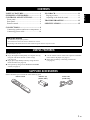 3
3
-
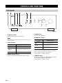 4
4
-
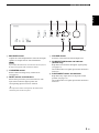 5
5
-
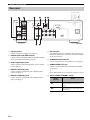 6
6
-
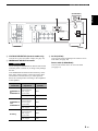 7
7
-
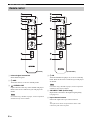 8
8
-
 9
9
-
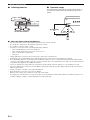 10
10
-
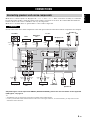 11
11
-
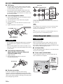 12
12
-
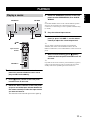 13
13
-
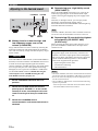 14
14
-
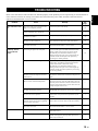 15
15
-
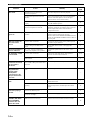 16
16
-
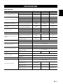 17
17
-
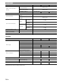 18
18
-
 19
19
-
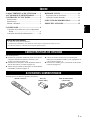 20
20
-
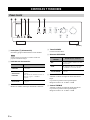 21
21
-
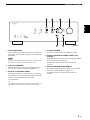 22
22
-
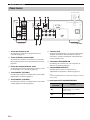 23
23
-
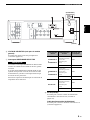 24
24
-
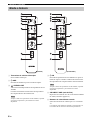 25
25
-
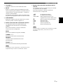 26
26
-
 27
27
-
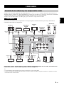 28
28
-
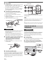 29
29
-
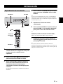 30
30
-
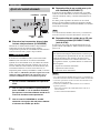 31
31
-
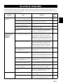 32
32
-
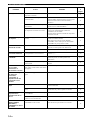 33
33
-
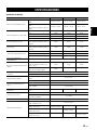 34
34
-
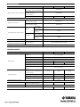 35
35


Yamaha A-S701 El manual del propietario
- Tipo
- El manual del propietario
en otros idiomas
- English: Yamaha A-S701 Owner's manual
Artículos relacionados
-
Yamaha A-S501 Manual de usuario
-
Yamaha A-S700 El manual del propietario
-
Yamaha A-S801 El manual del propietario
-
Yamaha R-S500 El manual del propietario
-
Yamaha DSP-Z11 El manual del propietario
-
Yamaha RX-797 El manual del propietario
-
-
Yamaha A-S300 El manual del propietario