Glacier Bay 2172WWHD Instrucciones de operación
- Tipo
- Instrucciones de operación

THANK YOU
We appreciate the trust and condence you have placed in Glacier Bay through the purchase of this pole caddy.
We strive to continually create quality products designed to enhance your home. Visit us online to see our full line of products
available for your home improvement needs. Thank you for choosing Glacier Bay!
USE AND CARE GUIDE
POLE CADDY
Questions, problems, missing parts?
Before returning to the store, call Glacier Bay Customer Service
8 a.m. - 7 p.m., EST, Monday - Friday, 9 a.m. - 6 p.m., EST, Saturday
1-855-HD-GLACIER
HOMEDEPOT.COM/GLACIERBAY
Item #1005 805 308
Model #2172WWHD

2
Table of Contents
Safety Information
Table of Contents ...................................2
Safety Information ..................................2
Warranty ..........................................2
Pre-Installation .....................................3
Planning Installation ...............................3
Packaging Content .................................4
Installation ........................................5
Care & Cleaning ....................................9
Troubleshooting ....................................9
□Read through this entire manual prior to assembly and installation.
Warranty
ONE YEAR LIMITED WARRANTY
WHAT IS COVERED
Glacier Bay products are manufactured with superior quality standards and workmanship and are backed by our limited lifetime warranty.
Glacier Bay products are warranted to the original consumer purchaser to be free of defects in materials or workmanship. We will replace
FREE OF CHARGE any product or parts that proves defective. Simply, return the product / part to any of The Home Depot retail locations or
call 1-855-HD-GLACIER to receive the replacement item. Proof of purchase (original sales receipt) from the original consumer purchaser
must be made available for all Glacier Bay warranty claims.
WHAT IS NOT COVERED
All costs of removing and reinstalling the product are the purchaser’s responsibility. Any alteration of this product or use of this product in
any manner other than its intended use shall automatically void this warranty. This warranty excludes incidental/inconsequential damages
and failures due to misuse, abuse or normal wear and tear. This warranty excludes all industrial, commercial & business usage, whose
purchasers are hereby, extended a ve year limited warranty from the date of purchase, with all other terms of this warranty applying
except the duration of warranty.
Some states and provinces do not allow the exclusion or limitation of incidental or consequential damages, so the above limitations
may not apply to you. This warranty gives you specic legal rights and you may also have other rights that vary from state to state and
province to province. Please see a store or contact 1-855-HD-GLACIER for more details.

3 HOMEDEPOT.COM/GLACIERBAY
Please contact 1-855-HD-GLACIER for further assistance.
PLANNING INSTALLATION
□Please identify all parts and hardware pieces before you begin.
□When laying out parts, place them on a soft surface to prevent scratching.
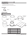
TOOLS REQUIRED
Tape Measure
HARDWARE INCLUDED
NOTE: Hardware shown to actual size.
G
Pre-Installation
rounded end inserts
into shelf collar
Part Description Quantity
G Small end cap 1
H Large end cap 1
J Wedge 3
K Transition ring 1
L Spring stopper 2
M Tape strip 1
HJ
MLK

4
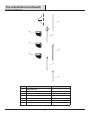
Pre-Installation (continued)
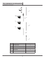
PACKAGE CONTENTS
Part Description Quantity
A Long tapered tube 1
B Medium tapered tube 1
C Short tapered tube 1
D Straight tube
(spring packed inside)
1
E 3/4 in. tube 1
FSpacer 3
G Shelf 3
A
B
C
D
E
G
G
G
F

5 HOMEDEPOT.COM/GLACIERBAY
Please contact 1-855-HD-GLACIER for further assistance.
Installation (continued)
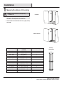
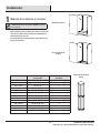
1 Measuring the distance to the ceiling
NOTE: No matter the distance, tubes (D) and (E)
are ALWAYS used.
□Measure the distance between the tub ledge or the shower
stall oor to the ceiling to the nearest half-inch.
□See the below chart to determine what tubes (A), (B) and/or (C)
are needed.
tub ledge
shower stall oor
Distance to Ceiling Tubes Used
as Needed
Number of Spacers (F) Used
60 - 61.5 in. (B), (D) and (E) 3
62 - 64 in. (A), (D) and (E) 2
64.5 - 67 in. (A), (D) and (E) 3
67.5 - 71 in. (A), (C), (D) and (E) 0
71.5 - 73 in. (A), (C), (D) and (E) 1
73.5 - 75 in. (A) (B), (D) and (E) 0
75.5 - 78 in. (A) (B), (D) and (E) 1
78.5 - 81 in. (A) (B), (D) and (E) 2
81.5 - 84.5 in. (A) (B), (C), (D) and (E) 3
85 - 88.5 in. (A), (B), (C), (D) and (E) 0
89 - 91.5 in. (A), (B), (C), (D) and (E) 1
92 - 95 in. (A), (B), (C), (D) and (E) 2
95.5 - 97 in. (A), (B), (C), (D) and (E) 3
Spacer (F)
shown below

6
Installation (continued)
B
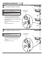
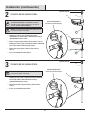
2 Connecting the shelves to the tube
NOTE: ASSEMBLY SHOWN FOR 97 IN. OPENING HEIGHT.
The following assembly should be modied based on your
opening height. SEE CHART ON PAGE 5.
NOTE: Shelves (G) can be adjusted by moving the
wedges (J) up or down.
□Place a wedge (J) (tapered or rounded end up) on the
long tapered tube (A) approximately half-way down.
□Slide the shelf (G) down the tube and t over the wedge (J).
□Place another wedge (J) (tapered or rounded end up) on the
long tapered tube (A).
□Slide another shelf (G) down the tube and t over the
wedge (J).
□This is the upper tube assembly.
3 Connecting the shelves to the tube
NOTE: Shelf (G) can be adjusted by moving the
wedges (J) up or down.
□Place a wedge (J) (tapered or rounded end up) on the
medium tapered tube (B) approximately half-way down.
□Slide the last shelf (G) down the tube and t over
the wedge (J).
□This is the lower tube assembly.
G
A
rounded end inserts
into shelf collar
rounded end inserts
into shelf collar
tapered end
tapered end
G
G
J
J
J

7 HOMEDEPOT.COM/GLACIERBAY
Please contact 1-855-HD-GLACIER for further assistance.
Installation (continued)
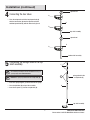
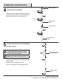
4 Connecting the two tubes
□Place the untapered end of the long tapered tube (A)
with the two shelves (G) onto the tapered end of the
medium tapered tube (B) with the other shelf (G) on it.
spring packed inside
straight tube (D)
tapered end
A
top shelf assembly
bottom shelf assembly
G
B
G
G
5 Connecting the straight tube to the top
shelf assembly
NOTE: ASSEMBLY SHOWN FOR 97 IN. OPENING HEIGHT.
The following assembly should be modied based on your
opening height. SEE CHART ON PAGE 5.
NOTE: The spring is packed inside the straight tube (D).
□Insert the spring stoppers (L) into the ends of the spring.
□Place straight tube (D) on top of the assembly.
□Insert three spacers (F) into the straight tube (D).
tapered end
F
top shelf assembly
D
L

8
Installation (continued)
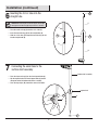
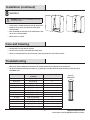
6 Inserting the 3/4 in. tube into the
straight tube
NOTE: After inserting the 3/4 in. tube (E) into the straight
tube (D), the transition ring (K) may need to be re-inserted.
□Place the small end cap (G) onto the 3/4 in. tube (E).
□Insert the transition ring (K) into the straight tube (D).
□Slide the 3/4 in. tube (E) through the transition ring (K) and
into the straight tube (D).
C
bottom shelf assembly
E
D
7 Connecting the small tube to the
bottom shelf assembly
□Place the large end cap (H) on the short tapered tube (C).
□Slip the tapered end of the short tapered tube (C) into the
untapered end of the bottom tube of the assembly.
□Place the tape strips (M) around the seams of the tubes.
E
D
tapered end
KK
H
G
M
C

9 HOMEDEPOT.COM/GLACIERBAY
Please contact 1-855-HD-GLACIER for further assistance.
[Heading goes here]
Care and Cleaning
□Cleaning with a dry cloth may be sufcient.
□For other stains or marks, wipe gently with a damp cloth.
□Do not use strong detergents or abrasive cleaners; they may damage the surface of this product.
Troubleshooting
□Measure the distance between the tub ledge or the shower stall oor to the ceiling to the nearest half-inch.
□See the chart below to determine what tubes (A), (B) and/or (C) are needed. NOTE: No matter the distance, tubes (D) and (E)
are ALWAYS used.
Distance to Ceiling Tubes Used
as Needed
Number of Spacers (F) Used
60 - 62 in. (B), (D) and (E) 3
62.5 - 64 in. (A), (D) and (E) 2
64.5 - 67.5 in. (A), (D) and (E) 3
68 - 71 in. (A), (C), (D) and (E) 0
71.5 - 74 in. (A), (C), (D) and (E) 1
74.5 - 75 in. (A) (B), (D) and (E) 0
75 - 78 in. (A) (B), (D) and (E) 1
78.5 - 81.5 in. (A) (B), (D) and (E) 2
82 - 85 in. (A) (B), (C), (D) and (E) 3
85.5 - 88.5 in. (A), (B), (C), (D) and (E) 0
89 - 91.5 in. (A), (B), (C), (D) and (E) 1
92 - 95 in. (A), (B), (C), (D) and (E) 2
95.5 - 97 in. (A), (B), (C), (D) and (E) 3
8 Installation
WARNING: Make sure you are installing in a clean, dry
and safe environment.
□Lift the entire assembly into position over the shower stall.
□Compress the top of the unit against the ceiling at the
desired location.
□Move the bottom end into place on the shower oor so that
the unit is in a vertical position.
□Adjust shelves as needed.
Installation (continued)
Spacer (F)
shown below

Questions, problems, missing parts?
Before returning to the store, call Glacier Bay Customer Service
8 a.m. - 7 p.m., EST, Monday - Friday, 9 a.m. - 6 p.m., EST, Saturday
1-855-HD-GLACIER
HOMEDEPOT.COM/GLACIERBAY
Retain this manual for future use.
IS2174

¡GRACIAS!
Agradecemos la conanza que ha depositado en Glacier Bay a través de la adquisición de esta barra organizadora. Nos esforzamos constantemente
en crear productos de calidad diseñados para embellecer su hogar. Visítenos en línea y vea nuestra línea completa de productos para realizar
mejoras en su hogar. ¡Gracias por elegir Glacier Bay!
GUÍA DE USO Y CUIDADO
ESTANTE ORGANIZADORA PARA REGADERA
¿Tiene preguntas, problemas, le faltan piezas?
Antes de regresar a la tienda, llame al Servicio al Cliente de Glacier Bay, de 8 a.m. - 7 p.m.,
Hora Estándar del Este, de lunes a viernes, de 9 a.m. - 6 p.m., Hora Estándar del Este, sábado
Importador/ Imported by: SERVICIOS HOME DEPOT, S. DE R.L. DE C.V.
Ricardo Margain 605, Santa Engracia, San Pedro Garza García, Nuevo León, México, C.P. 66267 Tel./Phone 01 800 004 6633
1-855-HD-GLACIER
Ítem #1005 805 308
Modelo #2172WWHD

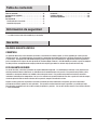
Tabla de contenido
Información de seguridad
Tabla de contenido. . . . . . . . . . . . . . . . . . . . . . . . . . . . . . . . . . . . 12
Información de seguridad ...........................12
Garantía. . . . . . . . . . . . . . . . . . . . . . . . . . . . . . . . . . . . . . . . . . 12
Pre-instalación ....................................13
Planicación de la instalación .......................13
Contenido del paquete .............................14
Instalación .......................................15
Cuidado y limpieza .................................19
Solución de problemas ..............................19
□Lea todo el manual antes del ensamblaje y la instalación.
Garantía
UN AÑO DE GARANTÍA LIMITADA
COBERTURA
Los productos Glacier Bay están fabricados con normas y manufactura de calidad superior y están respaldados por nuestra garantía
limitada de por vida. Los productos Glacier Bay garantizan al comprador consumidor original que están libres de defectos en materiales
o manufactura. Reemplazaremos SIN CARGO cualquier producto o partes que estén defectuosas. Simplemente devuelva el producto o
parte a cualquiera de los lugares de venta por menor de The Home Depot o llame al 1-855-HD GLACIER para recibir la parte de reemplazo.
Se debe presentar un comprobante de compra (recibo de venta original) para todos los reclamos bajo garantía de Glacier Bay.
ESTA GARANTÍA NO CUBRE
Los costos de retirar y reinstalar el producto son responsabilidad del comprador. Las modicaciones realizadas a este producto o uso
de dicho producto de manera diferente al uso indicado anularán automáticamente esta garantía. Esta garantía excluye daños y fallas
incidentales o emergentes debido a uso indebido, abuso o desgaste normal. Esta garantía excluye todo uso industrial, comercial o
institucional realizado por los compradores a los que se les extiende esta garantía limitada de cinco años a partir de la fecha de compra,
siendo de aplicación todos los demás términos de esta garantía, excepto la duración de la misma.
Algunos estados y provincias no permiten la exclusión o limitación de daños incidentales o emergentes, por ello las limitaciones
previamente enunciadas pueden no serles aplicables. Esta garantía le conere derechos legales especícos y es posible que tenga
otros derechos que pueden variar de estado a estado y de provincia a provincia. Para ver más detalles concurra a una tienda o contacte
a 1-855-HD-GLACIER.
12

PLANIFICACIÓN DE LA INSTALACIÓN
□Identique todas las piezas y las piezas de tornillería antes de comenzar.
□Al esparcir las partes, colóquelas sobre una supercie suave para evitar que se rayen.
HERRAMIENTAS NECESARIAS
Cinta métrica
ELEMENTOS INCLUIDOS
NOTA: La tornillería se ilustra en su
tamaño real.
Pre-instalación
GHJ
MLK
extremo redondeado se
inserta en el aro de la repisa
Pieza Descripción Cantidad
G Cubierta terminal pequeña 1
H Cubierta terminal grande 1
J Cuña 3
K Aro de transición 1
L Tope de resorte 2
M Tiras de cinta 1
13 HOMEDEPOT.COM/GLACIERBAY
Contáctese con 1-855-HD-GLACIER para recibir ayuda adicional.

14
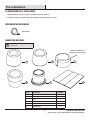
Pre-instalación (continuación)
CONTENIDO DEL PAQUETE
Pieza Descripción Cantidad
A Tubo largo ahusado 1
B Tubo mediano ahusado 1
C Tubo corto ahusado 1
DTubo recto
(con resorte embutido en su interior)
1
E Tubo de 1.9 cm 1
F Espaciador 3
GRepisa 3
A
B
C
D
E
G
G
G
F

15 HOMEDEPOT.COM/GLACIERBAY
Contáctese con 1-855-HD-GLACIER para recibir ayuda adicional.
Instalación (continuación)
1 Medición de la distancia al cielorraso
NOTA: Cualquiera sea la distancia, SIEMPRE se usan los
tubos (D) y (E).
□Mida la distancia entre el reborde de la bañera o el piso del
cubículo de la ducha hasta el cielorraso redondeando a la
media pulgada más cercana.
□Vea la siguiente tabla para determinar cuáles tubos (A), (B)
y/o (C) son necesarios.
reborde de la bañera
piso del cubículo de
la ducha
Distancia al cielorraso Tubos used según
sea necesario
Cantidad de espaciadores (F)
necesarios
152,5 - 156 cm (B), (D) y (E) 3
157,5 - 162,5 cm (A), (D) y (E) 2
164 - 170 cm (A), (D) y (E) 3
171,5 - 180 cm (A), (C), (D) y (E) 0
181,5 - 185,5 cm (A),(C) , (D) y (E) 1
181,5 - 185,5 cm (A), (B), (D) y (E) 0
187 - 190,5 cm (A), (B), (D) y (E) 1
192 - 198 cm (A), (B), (D) y (E) 2
199 - 206 cm (A),(B), (D) y (E) 3
216 - 225 cm (A), (B), (C), (D) y (E) 0
226 - 232,5 cm (A), (B), (C), (D) y (E) 1
234 - 241,5 cm (A), (B), (C), (D) y (E) 2
242,5 - 246,5 cm (A), (B), (C), (D) y (E) 3
Espaciador (F) mostrado
debajo

16
Instalación (continuación)
G
A
G
2 Conexión de las repisas al tubo
NOTA: ENSAMBLE MOSTRADO PARA INSTALACIÓN EN
ALTURA DE APERTURA DE 97 PULGADAS. El siguiente
ensamble se debe modicar basándose en la altura de
apertura. VER TABLA EN LA PÁGINA 15.
NOTA: Las repisas (G) se pueden regular desplazando las
cuñas (J) hacia arriba o hacia abajo.
□Coloque una cuña (J) (con el extremo ahusado o
redondeado hacia arriba) sobre el tubo largo ahusado (A)
aproximadamente por el centro.
□Deslice la repisa (G) por el tubo y cálcela sobre la cuña (J).
□Coloque otra cuña (J) (con el extremo ahusado o redondeado
hacia arriba) sobre el tubo largo ahusado (A).
□Deslice otra repisa (G) por el tubo y cálcela sobre la
cuña (J).
□Este es el ensamble del tubo superior.
3 Conexión de las repisas al tubo
NOTA: Las repisas (G) se pueden regular desplazando las
cuñas (J) hacia arriba o hacia abajo.
□Coloque una cuña (J) (con el extremo ahusado o redondeado
hacia arriba) sobre el tubo mediano ahusado (B)
aproximadamente por el centro.
□Deslice la otro repisa (G) por el tubo y cálcela sobre la
cuña (J).
□Este es el ensamble del tubo inferior.
extremo redondeado se
inserta en el aro de la repisa
extremo redondeado se
inserta en el aro de la repisa
extremo ahusado
extremo ahusado
B
G
J
J
J

17 HOMEDEPOT.COM/GLACIERBAY
Contáctese con 1-855-HD-GLACIER para recibir ayuda adicional.
Instalación (continuación)
4 Conexión de los dos tubos
□Coloque el extremo no ahusado del tubo largo ahusado (A)
con las dos repisas (G) sobre el extremo ahusado del tubo
mediano ahusado (B), con las repisas (G) sobre este.
resorte embutido dentro
del tubo recto (D)
extremo ahusado
ensamble del tubo
superior
ensamble del tubo
inferior
5 Conexión del tubo recto en el ensamble
del tubo superior
NOTA: ENSAMBLE MOSTRADO PARA INSTALACIÓN EN
ALTURA DE APERTURA DE 97 PULGADAS. El siguiente
ensamble se debe modicar basándose en la altura de
apertura. VER TABLA EN LA PÁGINA 15.
NOTA: Resorte embutido dentro del tubo recto (D).
□Inserte los topes del resorte (L) en los extremos del resorte,
como se ilustra.
□Coloque el tubo recto (D) sobre el ensamble.
□Inserte tres espaciadores (F) dentro del tubo recto (D).
extremo ahusado
ensamble de repisa
superior
A
G
B
G
G
F
D
L

18
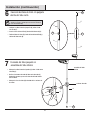
Instalación (continuación)
C
6
NOTA: Después de insertar el tubo de 1.9 cm (E) dentro
del tubo recto (D), es posible que sea necesario reinsertar
el aro de transición (K).
□Coloque la cubierta terminal pequeña (G) sobre el tubo
de 1.9 cm (E).
□Inserte el aro de transición (K) dentro del tubo recto (D).
□Deslice el tubo de 1.9 cm (E) a través del aro de transición (K) y
dentro del tubo recto (D).
ensamble del tubo
inferior
7 Conexión del tubo pequeño al
ensamble del tubo inferior
□Coloque la cubierta terminal grande (H) sobre el tubo corto
ahusado (C).
□Deslice el extremo ahusado del tubo corto ahusado (C)
dentro del extremo que no está ahusado del tubo inferior
del ensamble.
□Coloque las tiras de cinta (M) alrededor de las uniones de
los tubos. extremo ahusado
E
D
E
D
H
G
KK
Inserción del tubo de 8.64 cm pulgada
dentro del tubo recto
M
C

19 HOMEDEPOT.COM/GLACIERBAY
Contáctese con 1-855-HD-GLACIER para recibir ayuda adicional.
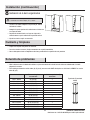
[Heading goes here]
Cuidado y limpieza
□Limpiar con un paño seco puede ser suciente.
□Para otras manchas o marcas, limpie suavemente con un paño humedecido.
□No use detergentes fuertes o limpiadores abrasivos; pueden dañar la supercie de este producto.
Solución de problemas
□Mida la distancia entre el reborde de la bañera o el piso del cubículo de la ducha hasta el cielorraso redondeando a la media
pulgada más cercana.
□Vea la tabla para determinar cuáles tubos (A), (B) y/o (C) son necesarios. NOTA: Cualquiera sea la distancia, SIEMPRE se usan los
tubos (D) y (E).
Distancia al cielorraso Tubos used según
sea necesario
Cantidad de espaciadores (F)
necesarios
152,5 - 156 cm (B), (D) y (E) 3
157,5 - 162,5 cm (A), (D) y (E) 2
164 - 170 cm (A), (D) y (E) 3
171,5 - 180 cm (A), (C), (D) y (E) 0
181,5 - 185,5 cm (A),(C) , (D) y (E) 1
181,5 - 185,5 cm (A), (B), (D) y (E) 0
187 - 190,5 cm (A), (B), (D) y (E) 1
192 - 198 cm (A), (B), (D) y (E) 2
199 - 206 cm (A),(B), (D) y (E) 3
216 - 225 cm (A), (B), (C), (D) y (E) 0
226 - 232,5 cm (A), (B), (C), (D) y (E) 1
234 - 241,5 cm (A), (B), (C), (D) y (E) 2
242,5 - 246,5 cm (A), (B), (C), (D) y (E) 3
8 Instalación de la barra organizadora
ADVERTENCIA: Asegúrese de que está haciendo una
instalación en un entorno limpio, seco y seguro.
□Levante el ensamble completo en la posición por sobre el
cubículo de la ducha.
□Comprima la parte superior de la unidad contra el cielorraso
en el lugar deseado.
□Desplace el extremo inferior a su lugar en el piso de la
ducha de manera que la unidad esté en posición vertical
□Ajuste los estant es según sea necesario.
Instalación (continuación)
Espaciador (F) mostrado
debajo

IS2174
¿Tiene preguntas, problemas, le faltan piezas?
Antes de regresar a la tienda, llame al Servicio al Cliente de Glacier Bay
8 a.m. - 7 p.m., Hora Estándar del Este, de lunes a viernes, de 9 a.m. - 6 p.m., Hora Estándar del Este, sábado
1-855-HD-GLACIER
HOMEDEPOT.COM/GLACIERBAY
Conserve este manual para consultar en el futuro.
-
 1
1
-
 2
2
-
 3
3
-
 4
4
-
 5
5
-
 6
6
-
 7
7
-
 8
8
-
 9
9
-
 10
10
-
 11
11
-
 12
12
-
 13
13
-
 14
14
-
 15
15
-
 16
16
-
 17
17
-
 18
18
-
 19
19
-
 20
20


