Roca A5A142ECN0 Guía de instalación
- Categoría
- Artículos sanitarios
- Tipo
- Guía de instalación
Este manual también es adecuado para

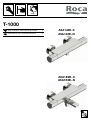
T-1000
ES Modo de empleo / Instrucciones de montaje 8
EN Instructions for use / assembly instructions 9
A5A142E..0
A5A142E..N
A5A1E2E..0
A5A1E2E..N

2

75 MAX.
MAX.
10
MAX.
5
MIN.
0,5
3
1
45 MIN. 65
50
< 2
A5A142E..0
A5A142E..N
A5A1E2E..0
A5A1E2E..N
160 max
200 min
750 - 800
1100 - 1200
ECO - 8
MAX. 15
325
150
Ø65
162,5
325
150
Ø65
162,5
180
P (bar)
20
87

A5A142E..0
A5A142E..N
A5A1E2E..0
A5A1E2E..N
1
2
4
6
11
8
9
7
10
5
3
2
1
1
2
4
13
12
14
8
9
7
10
5
3
2
1
11

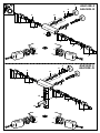
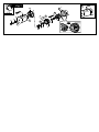
1 - AG02319..R
2 - AG0221200R
3 - AG0131603R
4 - AG0131903R
5 - AG0220900R
6 - A525016609
7 - AG01168..R 2 un.
8 - A525016207 2 un.
9 - AG0156900R 2 un.
10 - A525005507 2 un.
11 - AG02211..R
12 - AG00294..R
13 - AG0232000R
14 - AG0232100R

Fig. 2
Fig. 1
3
150
1
2
30
35-40
32-37
= 38ºC
2
4
3
1
B
D
E
A
C
2
1

Fig. 4
Fig. 5
Fig. 6
2
3
2
10
1
1
F
F
G
H
G
H
30
5
K
4
3
2
A
B
D
E
C
25
I
Fig. 3
D
E

Fig. 7
4
5
6
1
3
2
A
B
C
L
M
N
SOP
R
Q
25

9
ADVERTENCIAS DE LA INSTALACIÓN Y USO
El uso de acumuladores de presión permite conseguir el mejor ren-
dimiento de este aparato, obteniendo la mayor exactitud en relación
a la temperatura seleccionada. También pueden utilizarse los calen-
tadores instantáneos a gas si disponen de una potencia caloríca
suciente (18kW o 250 kcal/min). No puede utilizarse el producto
con acumuladores o calentadores de agua sin presión.
La presión dinámica no debe superar los 5 bar; si resulta necesario
deben instalarse reguladores de presión.
Las diferencias de presión dinámica entre agua fría y caliente no
deben ser superiores a 2 bar.
En condiciones de presión dinámicas compensadas , el agua de
mezcla a la salida de la grifería, con la temperatura seleccionada a
tope caliente, puede ser hasta 2º C inferior a la temperatura del agua
en la entrada caliente de la grifería.
Es necesario liberar de partículas las entradas de agua a la grifería
para evitar que se obstruyan los elementos anti-retorno o el cartucho
termostático . Instalar siempre los ltros que se suministran para las
entradas de agua a la grifería.
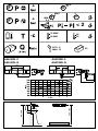
DATOS TÉCNICOS
Presión estática max max. 10 bar
Presión dinámica min/max 0, 5 - 5 bar
Presión dinámica recomendada 1 - 3 bar
Temperatura del agua caliente min/max 45/75ºC
Temp. recomendada del agua caliente 50 - 65ºC
INSTALACIÓN
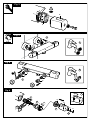
Montaje (Fig. 1)
1) Desinstalar la grifería antigüa (si la hubiera), así como sus excéntri-
cas y hacer circular el agua para liberar las partículas de las tuberías.
2) Ajustar las excéntricas respetando las medidas recomendadas para
la instalación.
3) Vericar que los paragrabillas están bien montados. Con la llave del
30 conectar la grifería a la pared.
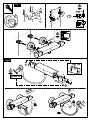
Ajuste de la temperatura (Fig. 2)
1) Girar el mando de temperatura hasta alinear la indicación de 38ºC
con el índice del anillo.
2) Girar el mando de caudal hacia baño y medir con termómetro la
temperatura del agua que sale. Si la lectura no es de 38ºC proceder
con el ajuste.
3) Con el mando de temperatura alineado según el paso 1, quitar la
tapa (A) del mando de temperatura haciendo palanca y extraer el
tornillo (B) y la arandela (C). Extraer la cruceta de temperatura (D) y
el casquillo de límite de recorrido (E).
4) Girar el eje del cartucho termostático hasta que la temperatura del
agua sea de 38ºC.
5) El montaje se efectúa en orden inverso (Fig. 3). Es importante montar
los componentes en el orden y posiciones indicados.
MANTENIMIENTO
Cerrar las llaves de paso del agua fría y del agua caliente.
Revisar y limpiar todas las piezas, cambiándolas en caso de necesidad
y engrasándolas con grasa especial para grifería.
Limpieza de paragrabillas (F) (Fig. 4)
1) Con la llave del 30 desconectar la grifería de la pared.
2) Limpiar o cambiar (ver imagen g 4.2).
Limpieza de válvula anti-retorno (G) (Fig. 5)
1) Con la llave del 30 desconectar la grifería de la pared
2) Con una llave de macho hexagonal de 10mm y girando a la derecha
(rosca a la izquierda), desenroscar el asiento (H).
3) Extraer los anti-retornos (G) con ayuda de una ganzúa. Limpiar o
cambiar y volver a montar.
4) El montaje se efectúa en orden inverso. Vericar que los paragra-
billas están bien montados. Con la llave del 30 conectar la grifería
a la pared.
Cartucho termostático (K) (Fig. 6)
1) Girar el mando de temperatura hasta alinear la indicación de 38ºC
con el índice del anillo.
2) Quitar la tapa (A) del mando de temperatura haciendo palanca y
extraer el tornillo (B) y la arandela (C).
3) Extraer la cruceta de temperatura (D) y el casquillo de límite de
recorrido (E).
4) Desenroscar la tuerca (I) con una llave de 25mm.
5) Extraer el cartucho (K) con ayuda de unos alicates haciendo un poco
de palanca. Limpiar de cal e impurezas o cambiar y volver a montar.
6) El montaje se efectúa en sentido inverso. Después de cada opera-
ción de mantenimiento en el cartucho termostático, es necesario un
ajuste (véase Ajuste de la temperatura).
Desviador cerámico (Fig. 7)
1) Girar el mando de caudal a su punto de cierre.
2) Quitar la tapa (A) del mando de caudal haciendo palanca y extraer
el tornillo (B) y la arandela (C).
3) Extraer la cruceta de caudal (L) y el casquillo de límite de recorrido
(M).
4) Extraer el casquillo de arrastre (N), la arandela de retención (S) y el
casquillo de guía (O).
5) Desenroscar la tuerca (P) y su junta tórica con una llave de 25mm.
6) Extraer el desviador (Q) y la junta laviada (R). Limpiar o cambiar y
volver a montar.
7) El montaje se efectúa en sentido inverso. La válvula debe montarse
en su posición de cierre, llevando los ejes posicionadores a los ori-
cios del núcleo termostático. Es importante montar los componentes
en el orden y posiciones indicados.
ES
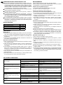
SOLUCIÓN DE PROBLEMAS
Problema Causa Solución
Sale poca agua
Presión en la alimantación insuciente. Comprobar presión en la alimentación fría y caliente.
Filtros de la grifería sucios. Limpiar los ltros en las tomas de alimantación y el cartu-
cho termostático.
Filtro de la ducha sucio. Limpiar / Cambiar ltro entre el exo y la ducha de mano.
Flujo de agua cruzada, ujo de agua caliente
entra en la tubería del agua fría o al revés
Válvula antirretorno de las alimentaciones sucia
u obstruida.
Limpiar / Cambiar las válvulas de las entradas de agua fría
y caliente.
Temperatura del agua no corresponde a la
seleccionada
Cartucho termostático no ajustado a la
instalación. Ajustar el cartucho termostático a la instalación.
Temperatura del agua caliente demasiado baja.
- Aumentar la temperatura del agua caliente a 45º-65ºC.
- Vericar que las presiones de alimentación están en el
rango recomendado.
- Vericar que la descompensación de presiones es inferior
a 2bar.
No es posible regular la temperatura Cartucho termostático calcicado o desgastado. Limpiar / cambiar el cartucho termostático.
Calentador instantáneo no se enciende
cuando el
cartucho termostático mezcla agua caliente
con agua fría
Filtros de la grifería sucios. Limpiar los ltros en las tomas de alimantación y el cartu-
cho termostático.
Válvula antirretorno en la toma caliente cerrada. Cambiar la válvula antirretorno de la toma caliente.
No se ha quitado limitador de caudal de la ducha
de mano. Quitar limitador de caudal.
Pierde permanentemente agua por una de
las salidas
Suciedad / sedimentaciones en el asiento de la
llave, o llave dañada. Limpiar / cambiar llave de obturación y selección.
Ruido
Presión en la alimantación alta. Comprobar presión en la alimentación fría y caliente.
Los antirruidos no trabajan bien. Comprobar si los antirruidos están dañados o mal insta-
lados.

10
INSTALLATION AND USE WARNINGS
The use of pressure accumulators allows to achieve the best perfor-
mance of this device, obtaining the highest accuracy in relation to the
selected temperature. Gas instantaneous heaters can also be used
if they have sucient heating power (18kW or 250 kcal / min). The
product cannot be used with accumulators or unpressurized water
heaters.
The dynamic pressure must not exceed 5 bar; if necessary pressure
regulators must be installed.
The dynamic pressure dierences between hot and cold water are
not they must be greater than 2 bar.
Under dynamic pressure compensated conditions, the mixing water
at the outlet of the faucet, with the temperature selected at hot top,
can be up to 2 ° C lower than the water temperature in the hot inlet of
the faucet.
It is necessary to free the water inlets to the faucet from particles to
avoid clogging of the anti-return elements or the cartridge thermosta-
tic. Always install the lters supplied for the water inlets to the faucet.
TECHNICAL DATA
Static pressure max max. 10 bar
Dynamic pressure min / max 0, 5 - 5 bar
Recommended dynamic pressure 1 - 3 bar
Hot water temperature min / max 45/75ºC
Temp. recommended hot water 50 - 65ºC
INSTALLATION
Assembly (Fig. 1)
1) Uninstall the old faucet (if any), as well as its eccentrics and circulate
the water to release the particles from the pipes.
2) Adjust the eccentrics respecting the recommended measurements
for installation.
3) Check that the lter mesh screen are properly mounted. With the key
of 30 connect the faucet to the wall.
Setting the temperature (Fig. 2)
1) Turn the temperature knob until the 38ºC indication aligns with the
index of the ring.
2) Turn the ow control towards shower and measure with a thermome-
ter the temperature of the water that comes out. If the reading is not
38ºC, proceed with trim.
3) With the temperature knob aligned per step 1, remove the cover (A)
of the temperature control lever and remove the screw (B) and was-
her (C). Remove the temperature crosshead (D) and the travel limit
bushing (E).
4) Rotate the shaft of the thermostatic cartridge until the temperature
of the water is 38ºC.
5) The assembly is carried out in the reverse order (Fig. 3). It is impor-
tant to mount the components in the order and positions indicated.
MAINTENANCE
Close the cold and hot water taps. Check and clean all parts, changing
them if necessary and gre sing them with special grease for taps.
Cleaning the grille guard (F) (Fig. 4)
1) Using the 30 key, disconnect the faucet from the wall.
2) Clean or replace (see image g 4.2).
Cleaning the non-return valve (G) (Fig. 5)
1) Using the 30 key, disconnect the tap from the wall
2) Using a 10mm hex socket wrench and turning clockwise (left-hand
thread), unscrew the seat (H).
3) Extract the anti-returns (G) with the help of a pick. Clean or change
and reassemble.
4) Assembly is carried out in reverse order. Check that the grille bars
they are well mounted. Use the 30 key to connect the faucet to the
wall.
Thermostatic cartridge (K) (Fig. 6)
1) Turn the temperature knob and align the 38ºC indication with the
reference index.
2) Remove the cover (A), the screw (B), the washer (C), the temperature
knob (D) and the bush (E).
3) Unscrew the nut (I) with a 25mm spanner.
4) Extract the cartridge (K) with the aid of pliers doing a smooth rocking
movement. Clean of lime and impurities or change and reassemble
in reverse order.
5) Turn the thermostatic cartridge shaft until the temperature is set to
38ºC.
6) Reassemble the components as shown at (Fig. 3). It is important to
mount the components in the order and relative position specied.
Ceramic diverter (Fig. 7)
1) Turn the ow control to closed position.
2) Remove the cover (A), the screw (B), the washer (C), the ow knob
(L) and the bush (M).
4) Remove the drive bush (N), the retention washer (S) and the bush
(O).
5) Unscrew the nut & o-ring (P) with a 25mm spanner.
6) Remove the diverter (Q) and the V joint (R). Clean or change and
reassemble.
7) Reassemble in reverse order. The diverter must be mounted, at clo-
sed position, as shown at Fig.7. It is important to mount the compo-
nents in the order and relative position specied.
EN
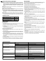
PROBLEM SOLVING
Problem Cause Solution
Low water ow delivered
Water inlet pressure lower to recommendation Check pressure at hot and cold water inlets
Dirt inlet lters Clean/change the inlet lters
Dirt thermostatic cartridge lters Clean the thermostatic cartridge lter
Dirt hand shower lter Clean / Change the lter at the hand shower
Cross water ow, hot water ows to cold
water pipe or vice versa Inlet water check valves dirt or obstructed. Clean / Change the check valves.
Outlet water temperature does not match
water temperature selection.
Calcied or worn thermostatic cartridge. Adjust the thermostatic cartridge to the installation
conditions.
Hot water temperature too low.
- Increase the temperature at the hot water inlet to 45º-
65ºC.
- Verify that the inlet pressures are in the recommended
range.
- Check that the pressure decompensation (Cold inlet
pressure –Hot inlet pressure) is less than 2bar.
It is not possible to select a temperature Calcied or worn thermostatic cartridge. Clean / change the thermostatic cartridge.
Instant heater does not turn on when the
thermostatic cartridge mixes hot water with
cold water
Dirt faucet lters. Clean/change the inlet lters and/or the thermostatic
cartridge lters.
Check valves blocked. Change/ clean the check valves.
Water ow is too low. Remove the ow limiter at the hand shower.
The faucet does not shut o. Dirt / broken diverter. Clean / change the diverter.
Noise
High inlet water pressure. Check hot and cold water inlet pressure.
Noise reducers do not work well. Check if the noise reducers at the eccentrics are damaged
or incorrectly installed

11

A553087607ah
Roca Sanitario, S.A.
Avda. Diagonal, 513
08029 Barcelona
SPAIN
www.roca.com
-
 1
1
-
 2
2
-
 3
3
-
 4
4
-
 5
5
-
 6
6
-
 7
7
-
 8
8
-
 9
9
-
 10
10
-
 11
11
-
 12
12


Roca A5A142ECN0 Guía de instalación
- Categoría
- Artículos sanitarios
- Tipo
- Guía de instalación
- Este manual también es adecuado para
En otros idiomas
- English: Roca A5A142ECN0 Installation guide