ATEN CL1000N Guía de inicio rápido
- Categoría
- Conmutadores KVM
- Tipo
- Guía de inicio rápido
El ATEN CL1000N es una consola LCD de 19 pulgadas que proporciona una solución de acceso remoto, integrando un teclado, un panel táctil y una pantalla LCD en un solo dispositivo compacto. Simplifica la gestión de servidores en salas de servidores, centros de datos y otras ubicaciones remotas.
El ATEN CL1000N es una consola LCD de 19 pulgadas que proporciona una solución de acceso remoto, integrando un teclado, un panel táctil y una pantalla LCD en un solo dispositivo compacto. Simplifica la gestión de servidores en salas de servidores, centros de datos y otras ubicaciones remotas.


Transcripción de documentos
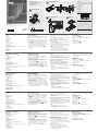
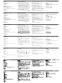
Package Contents 1 CL1000N with Standard Mounting Kit 1 Custom KVM Cable Set 1 Power Cord 1 User Instructions A 2 Important Notice Considering environmental protection, ATEN does not provide a fully printed user manual for this product. If the information contained in the Quick Start Guide is not enough for you to configure and operate your product, please visit our website www.aten.com, and download the full user manual. L Brackets Online Registration http://eservice.aten.com Technical Phone Support International: 886-2-86926959 Side Mountng Brackets B-1 North America: 1-888-999-ATEN Ext: 4988 B-2 United Kingdom: 44-8-4481-58923 B-3 The following contains information that relates to China: 1 2 3 11 CL1000N Hardware Installation Hardware Review Front View 19" LCD Console Quick Start Guide B C 5 EXIT I LIGHT 10 6 Hardware Installation 3 Operation EMC Information 4 FEDERAL COMMUNICATIONS COMMISSION INTERFERENCE STATEMENT: This equipment has been tested and found to comply with the limits for a Class A digital device, pursuant to Part 15 of the FCC Rules. These limits are designed to provide reasonable protection against harmful interference when the equipment is operated in a commercial environment. This equipment generates, uses, and can radiate radio frequency energy and, if not installed and used in accordance with the instruction manual, may cause harmful interference to radio communications. Operation of this equipment in a residential area is likely to cause harmful interference in which case the user will be required to correct the interference at his own expense. FCC Caution: Any changes or modifications not expressly approved by the party responsible for compliance could void the user's authority to operate this equipment. CE Warning: This is a class A product. In a domestic environment this product may cause radio interference in which case the user may be required to take adequate measures. 1 9 7 D Press the Exit/Light pushbutton for two seconds to turn the LED light ON or Off. (Default: On) D-1 8 CS1716A © Copyright 2015 ATEN® International Co., Ltd. ATEN and the ATEN logo are trademarks of ATEN International Co., Ltd. All rights reserved. All other trademarks are the property of their respective owners. 1 This product is RoHS compliant. Part No. PAPE-1223-A11G Rear View 2 2 3 Printing Date: 01/2015 D-2 USB All information, documentation, firmware, software utilities, and specifications contained in this package are subject to change without prior notification by the manufacturer. Please visit our website http:// www.aten.com/download/?cid=dds for the most up-to-date versions. PS/2 CL1000N 19" LCD Console Quick Start Guide Hardware Review www.aten.com Hardware Installation A Front View Standard Rack Mounting 1. Handle 2. Slide Release 3. LCD Display 4. LCD Controls 5. Keyboard 6. Touchpad 7. CPU LED* 8. Rack Mounting Brackets 9. Lock LEDs 10. LCD On / Off Button 11. LED Illumination Light * For CL1000N, lights to indicate that the unit is connected to the KVM (CPU) port B A standard rack mount kit is provided with your CL1000N. The kit enables the console to be mounted in rack with a depth of 52–85 cm. 1. While one person positions the CL1000N in the rack and holds it in place, the second person loosely screws the front brackets to the rack. B-1 2. While the first person still holds the CL1000N in place, the second person slides the L brackets into the CL1000N's side mounting brackets from the rear until the bracket flanges contact the rack, then screws the L brackets to the rack. B-2 3. After the L brackets have been secured, tighten the front bracket screws. B-3 Rear View 1. Power Socket 2. KVM(CPU) Port Note: • It takes two people to mount the unit: one to hold it in place; the other to screw it in. • Optional mounting kits – including single person Easy Installation kits – are available with a separate purchase. Refer to the installation diagram as you perform the installation steps: C 1. Plug the SPHD connector end of the KVM cable provided with this unit into the CL1000N's KVM port. 2. Plug the keyboard, monitor, and mouse connectors of the KVM cable provided with this unit into the 5 in 1 console cable that connected to the section of the KVM switch. Note: • Supports PS/2 or USB KVM switches • Supports computers with PS/2 or USB keyboard and mice 3. Plug the power cord into the CL1000N's power socket and into an AC power source to power up your KVM installation. Operation D Opening the console D-1 1. Push the catches inward. 2. Slide the module all the way out until it automatically locks in place. 3. Open the cover Closing the console D-2 1. Close the cover 2. Push the module all the way in Console LCD 19’’ CL1000N – Guide de démarrage rapide Description de l’appareil www.aten.com Installation du matériel A Vue avant Montage sur rack standard 1. Poignée 2. Bouton coulissant d'ouverture 3. Écran LCD 4. Commandes LCD 5. Clavier 6. Pavé tactile 7. Voyant du port CPU* 8. Supports de fixation pour montage sur bâti 9. Voyants de verrouillage 10. Bouton marche/arrêt de l’écran LCD 11. Eclairage LED * Pour la console CL1000N, ce voyant s’allume afin d’indiquer que l’unité est connectée au port KVM (CPU) B Un kit de montage sur rack standard est fourni avec le CL1000N. Ce kit permet de monter le commutateur sur rack, avec une profondeur de 52 à 85 cm. B-1 1. Pendant qu'une première personne positionne le commutateur dans le rack et le maintient en place, une deuxième visse les supports avant sur le bâti. B-2 2 Pendant que la première personne maintient toujours en place le commutateur, la deuxième fait glisser les supports en L dans les supports de montage latéraux du commutateur, à l'arrière, jusqu'à ce que les brides des supports entrent en contact avec le bâti, puis visse les supports en L sur le bâti. B-3 3. Une fois les supports en L sécurisés, serrez les vis des supports avant. Vue arrière 1. Prise d'alimentation 2. Port KVM (CPU) Remarque : • Deux personnes sont nécessaires pour monter l’unité : une pour la tenir en place et l'autre pour la visser. • Des kits de montage en option, y compris des kits faciles à installer par une seule personne, sont disponibles séparément. Reportez-vous au schéma d'installation pendant les différentes étapes de l’installation : C 1. Branchez le connecteur SPHD à 15 broches du câble KVM fourni avec cette unité sur le port KVM du CL1000N. 2. Branchez les connecteurs du clavier, du moniteur et de la souris du câble KVM fourni sur le câble de console 5 en 1 qui est connecté à la section correspondante du commutateur KVM. Remarque : • Prend en charge les commutateurs KVM PS/2 ou USB • Prend en charge les ordinateurs équipés de claviers et souris PS/2 ou USB 3. Branchez le cordon d’alimentation dans la prise d’alimentation de la CL1000N et dans une source d’alimentation CA pour alimenter votre installation KVM. Opération D Ouverture de la console D-1 Fermeture de la console D-2 1. Poussez les loquets vers l’intérieur. 2. Faites coulisser le module à fond vers l’extérieur jusqu’à ce qu’il se verrouille en place. 3. Ouvrez le couvercle 1. Fermez le couvercle 2. Poussez le module à fond vers l’intérieur CL1000N 19-Zoll-LCD-Konsole Kurzanleitung Hardwareübersicht www.aten.com Hardware installieren: A StandardRackMontage Vorderseitige Ansicht 1. Griff 2. Ausziehentriegelung 3. LCDDisplay 4. LCDBedienelemente 5. Tastatur 6. Touchpad 7. CPU-LED-Anzeige* 8. Schienen für die Rackmontage 9. Verriegelungs-LEDs 10. Ein-/Ausschalter für LCD-Schirm 11. LED-Beleuchtung * Leuchtet beim CL1000N auf, wenn das Gerät mit dem KVM- bzw. CPU-Port verbunden ist. B Mit dem CL1000N wird ein Montagekit für ein StandardRack mitgeliefert. Mit diesem Kit können Sie den Switch in ein Rack mit einer Tiefe von 52-85 cm einbauen. B-1 1. Während die eine Person den Switch in den Rack schiebt und festhält, setzt die zweite Person die Schrauben lose auf die Montageschienen. B-2 2. Während die erste Person den Switch nach wie vor festhält, schiebt die zweite die L-Schienen von hinten auf die seitlichen Montagerahmen des Switches, bis der Flansch den Rack berührt. Schrauben Sie die L-Schienen anschließend am Rack fest. B-3 3. Nachdem Sie die L-Schienen befestigt haben, ziehen Sie auch die Schrauben an der Vorderseite fest. Rückseitige Ansicht 1. Netzeingangsbuchse 2. KVM-Port (CPU-Port) Hinweis: • Zur Montage sind zwei Personen erforderlich: eine zum Festhalten und die andere zum Verschrauben der Einheit. • Optionale Montagekits – darunter auch solche, die durch eine Einzelperson installiert werden können – sind optional erhältlich. Für die Durchführung der folgenden Schritte, siehe das Installationsdiagramm: C 1. Verbinden Sie den 15poligen SPHDAnschluss des mitgelieferten KVMKabels mit dem KVMPort am CL1000N. 2. Verbinden Sie die Tastatur-, Monitor- und Mausanschlüsse des mitgelieferten KVM-Kabels mit den betreffenden Ports des 5-in1-Konsolkabels, das an den entsprechenden Abschnitt des KVMSwitches angeschlossen ist. Hinweis: • Unterstützt PS/2- oder USB-KVM-Switches • Unterstützt Computer mit PS/2- oder USB-Tastatur und -Maus 3. Verbinden Sie das Netzkabel mit der Stromeingangsbuchse des CL1000N und dem Stromnetz, um Ihre KVM-Installation mit Strom zu versorgen. Betrieb D Konsole öffnen D-1 1. Schieben Sie die Riegel zusammen. 2. Ziehen Sie das Modul ganz heraus, bis es eigenständig einrastet. 3. Klappen Sie es auf. Konsole schließen D-2 1. Klappen Sie das Modul zu. 2. Schieben Sie das Modul ganz hinein. CL1000N Consola con pantalla LCD de 19 pulgadas Guía rápida Presentación del hardware A Vista frontal 1. Asa 2. Desbloqueo retráctil 3. Pantalla LCD 4. Controles LCD 5. Teclado 6. Panel táctil 7. Indicador LED de CPU* 8. Escuadras para montaje en rack 9. Indicadores LED de bloqueo 10. Botón encender/apagar LCD 11. Iluminacion LED * Se ilumina para indicar que el CL1000N está conectado al puerto KVM (CPU). www.aten.com Instalación del hardware: Montaje en rack estándar B Con el CL1000N viene un kit de montaje en rack estándar. Con este kit puede montarlo en un rack con una profundidad entre 52 y 85 cm. B-1 1. Mientras una persona coloca el conmutador en el rack y lo aguanta en su sitio, una segunda atornilla (sin apretar) la parte frontal de los raíles en el rack. B-2 2. Mientras la primera persona sigue aguantando el conmutador, la segunda desliza los raíles en L sobre el conmutador desde la parte trasera hasta que la pestaña del soporte haga contacto con el rack y luego atornilla los raíles en L al rack. B-3 3. Cuando tenga los raíles en L atornillados, apriete también los tornillos frontales de los raíles. Vista posterior 1. Entrada de alimentación 2. Puerto KVM (CPU) Nota: • Hacen falta dos personas para instalar la unidad: una que la coloca en su sitio y la otra que la atornilla. • Existen kits de montaje opcionales – incluyendo kits de montaje para una sola persona. Véase el diagrama de instalación cuando vaya a efectuar los pasos listados a continuación: C 1. Enchufe el conector SPHD de 15 patillas del cable KVM incluido al puerto KVM del CL1000N. 2. Enchufe los conectores para teclado, monitor y mouse del cable KVM incluido al cable 5 en 1 de consola que está conectado a la sección correspondiente del conmutador KVM. Nota: • Admite conmutadores KVM de tipo PS/2 o USB • Admite computadoras con configuraciones de teclado y de mouse PS/2 o USB 3. Enchufe el cable de alimentación a la entrada de alimentación del CL1000N y a una toma eléctrica para encender su instalación de KVM. Funcionamiento Abrir la consola D D-1 1. Empuje los pestillos hacia dentro. 2. Saque el módulo del todo hasta que quede encajado automáticamente. 3. Abra el panel. Cerrar la consola D-2 1. Cierre el panel. 2. Empuje el modulo completamente hacia dentro. Console CL1000N con schermo LCD da 19 pollici – Guida rapida Panoramica sull’hardware A Vista anteriore 1. Maniglia 2. Sganciamento della slitta retraibile: 3. Display a cristalli liquidi 4. Comandi LCD 5. Tastiera 6. Touchpad 7. LED della CPU* 8. Staffe per il montaggio in rack 9. LED di blocco 10. Pulsante di accensione/spegnimento dello schermo 11. Illuminazione LED * Per la CL1000N, si illumina per indicare che l’unità è connessa alla porta KVM (CPU) Vista posteriore 1. Presa per l’alimentazione 2. Porta KVM (CPU) www.aten.com Installazione dell’hardware: Montaggio in rack standard B Un kit standard di montaggio su rack fine fornito insieme all'unità CL1000N. Il kit consente il montaggio dello switch su rack con una profondità di 52-85 cm. B-1 1. Mentre una persona posiziona lo switch nel rack e lo mette in posizione, la seconda persona fissa provvisoriamente i supporti frontali al rack. B-2 2. Mentre la prima persona continua a tenere in posizione lo switch, la seconda fa scivolare i supporti a L nei supporti laterali di montaggio dello switch, partendo dal retro, fino a quando non sono a stretto contatto con il rack e poi, utilizzando le viti in dotazione al kit, avvita i supporti a L al rack. B-3 3. Una volta fissati i supporti a L, stringere le viti dei supporti anteriori. Nota: • Per montare l’unità sono necessarie due persone: una per tenerla ferma in posizione, l’altra per avvitarla. • I kit di montaggio opzionali – compresi i kit d’installazione facile per una sola persona – sono disponibili in vendita separatamente. Nell’eseguire i punti successivi fare riferimento al diagramma d’installazione: C 1. Inserire l’estremità del connettore SPHD a 15 pin del cavo KVM fornito con il dispositivo nella porta KVM del CL1000N. 2. Inserire i connettori della tastiera, del monitor e del mouse del cavo KVM fornito con l’unità nel cavo console 5 in 1 collegato alla sezione dello switch KVM. Nota: • Supporta switch KVM PS/2 o USB • Supporta computer con tastiere e mouse PS/2 o USB 3. Inserire la spina del cavo dell’alimentazione nella presa dell’alimentazione della CL1000N e in una presa d’alimentazione CA per alimentare l’installazione KVM. Funzionamento D Funzionamento della console: D-1 1. Spingere verso l’interno le chiusure. 2. Far scivolare completamente fuori il modulo fino a quando non si fissa in posizione. 3. Aprire il coperchio Chiusura della console: D-2 1. Chiudere il coperchio 2. Far rientrare completamente il modulo www.aten.com Краткое руководство пользователя ЖК-консоли 19” CL1000N Обзор оборудования A Вид спереди 1. Ручка 2. Фиксатор выдвигания 3. ЖК-дисплей 4. Управление ЖК-дисплеем 5. Клавиатура 6. Тачпад 7. Индикатор ЦП* 8. Кронштейны для монтажа в стойке 9. Индикаторы блокировки 10. Кнопка включения/выключения ЖК-дисплея 11. Светодиодная подсветка * В модели CL1000N горит, сообщая о подключении устройства к порту KVM (ЦП) Вид сзади 1. Разъем питания 2. Порт KVM (ЦП) Установка оборудованияn Установка в стандартной стойке B Ваш CL1000N предоставляется вместе с комплектом для монтажа в стандартной стойке. Этот комплект используется для установки переключателя в стойке глубиной 52-85 см. 1. Пока один человека размещает переключатель в стойке и удерживает его, второй человек не полностью прикручивает винты передних кронштейнов к стойке. B-1 2. Пока первый человек продолжает удерживать переключатель в выбранном положении, второй человек задвигает Г-образные кронштейны в боковые монтажные кронштейны переключателя сзади до тех пор, пока фланцы кронштейнов не коснутся стойки, после чего прикручивает Г-образные кронштейны к стойке. B-1 3. После того как Г-образные кронштейны закреплены, полностью закрутите винты передних кронштейнов. B-1 Примечание. • Для установки устройства требуется два человека: один удерживает, а другой прикручивает. • Дополнительные монтажные комплекты, включая рассчитанные на одного человека комплекты упрощенной установки, приобретаются отдельно. 3. Подключите шнур питания к гнезду питания CL1000N и источнику переменного тока, чтобы включить KVM-систему. Консоль D Открывание консоли D-1 1. Вставьте задвижки. 2. Полностью выдвиньте модуль до автоматической фиксации. 3. Откройте крышку. Пользуясь приведенной схемой установки, выполните следующие шаги: C 1. Подключите разъем SPHD KVM-кабеля, идущего в комплекте с данным устройством, к порту KVM устройства 2. Подключите разъемы клавиатуры, монитора и мыши кабеля KVM, идущего в комплекте с данным устройством, в кабель консоли 5-в-1, подключенный к области KVM-переключателя. Примечание. • Поддержка PS/2 или USB KVM-переключателей • Поддержка компьютеров с клавиатурами и мышами PS/2 или USB Закрывание консоли D-2 1. Закройте крышку. 2. Вставьте модуль до упора. www.aten.com Короткий посібник користувача РК-консолі 19” CL1000N Огляд обладнання Встановлення обладнання A Вигляд спереду 1. Ручка 2. Фіксатор висування 3. РК-дисплей 4. Керування РК-дисплея 5. Клавіатура 6. Тачпад 7. Індикатор ЦП* 8. Кронштейни для монтажу у стійку 9. Індикатори блокування 10. Кнопка увімкнення/вимкнення РК-дисплею 11. Світлодіодне підсвічування * В моделі CL1000N індикатор світиться, якщо пристрій підключено до порту KVM (ЦП) Вигляд ззаду Встановлення в стандартній стійці B Ваш CL1000N постачається із комплектом для монтажу у стандартну стійку. Цей комплект використовується для встановлення перемикача у стійці глибиною 52-85 см. 1. Поки одна людина розміщує перемикач у стійці та тримає його, інша людина не повністю прикручує гвинти передніх кронштейнів до стійки. B-1 2. Поки перша людина продовжує тримати перемикач у вибраному положенні, інша людина засовує Г-образні кронштейни у бокові монтажні кронштейни перемикача ззаду доти, доки фланці кронштейнів не торкнуться стійки, після чого прикручує Г-образні кронштейни до стійки. B-2 3. Після того як Г-образні кронштейни закріплені, повністю закрутіть гвинти передніх кронштейнів. B-3 1. Гніздо живлення 2. Порт KVM (ЦП) Примітка. • Для встановлення пристрою потрібні дві людини: одна людина тримає, а інша закручує. • Додаткові монтажні комплекти, включно із розрахованими на одну людину комплектами спрощеного встановлення, купуються окремо. • Підтримка комп’ютерів з клавіатурами та мишами PS/2 або USB 3. Підключіть шнур живлення до гнізда живлення CL1000N та джерела змінного струму, щоб увімкнути систему KVM. Консоль D Відкривання консолі Користуючись наведеною схемою встановлення, виконайте наступні кроки: C 1. Підключіть з’єднувач SPHD кабелю KVM, що іде в комплекті з даним пристроєм, до порту KVM CL1000N. 2. Підключіть з’єднувачі клавіатури, монітора та миші кабелю KVM, наданого у комплекті з даним пристроєм, до консольного кабелю 5-в-1, що підключено до області KVMперемикача. Примітка. • Підтримка PS/2 або USB KVM-перемикачів D-1 1. Вставте засувки. 2. Повністю висуньте модуль до автоматичної фіксації. 3. Відкрийте кришку. Закривання консолі D-2 1. Закрийте кришку. 2. Вставте модуль повністю. www.aten.com Guia de início rápido do console LCD 19” CL1000N Revisão do hardware A Vista frontal 1. Alça 2. Desbloqueio retrátil 3. Monitor LCD 4. Controles LCD 5. Teclado 6. Touchpad 7. LED da CPU* 8. Suportes para montagem em bastidor 9. LEDs de bloqueio 10. Botão Ligar/Desligar LCD 11. Luz de iluminação de LED * No CL1000N, ascende para indicar que a unidade está conectada à porta KVM (CPU) Vista traseira Instalação de hardware Montagem em bastidor padrão B O CL1000N inclui um kit de montagem em bastidor padrão. O kit permite que o comutador seja montado em um bastidor com uma profundidade de 52-85cm. 1. Enquanto uma pessoa posiciona e segura o comutador no bastidor, a segunda pessoa parafusa os suportes frontais ao bastidor sem apertar. B-1 2. Enquanto a primeira pessoa ainda segura o comutador no lugar, a segunda pessoa desliza os suportes L nos suportes de tocarem o bastidor, depois parafusa os suportes L ao bastidor. B-2 suporte frontal. B-3 Observação: • São necessárias duas pessoas para montar a unidade: uma para segurá-la no lugar, outra para apertar os parafusos. • Estão disponíveis kits de montagem opcionais – incluindo kits de instalação fácil para uma pessoa – em uma compra à parte. Consulte a instalação de exemplo enquanto executa os seguintes passos de instalação: C 1. Conecte a ponta do conector SPHD do cabo KVM fornecido com esta unidade à porta KVM do CL1000N. 2. Ligue os conectores de teclado, monitor e mouse do cabo KVM fornecido com esta unidade ao cabo do console 5-em-1 que está conectado à divisão do comutador KVM. Observação: • Suporta comutadores KVM USB ou PS/2 • Suporta computadores com teclado e mouse PS/2 ou USB 3. Conecte o cabo de alimentação à tomada de energia do CL1000N e a uma fonte de alimentação AC para ligar sua instalação KVM. Operaçãoo Abrir o console D D-1 1. Empurre as travas para dentro. 2. Deslize o módulo para fora até que seja travado automaticamente. 3. Abra o painel. Fechar o console D-2 1. Feche o painel. 1. Tomada de energia 2. Porta KVM (CPU) CL1000N 19インチLCD搭載コンソールドロワー クイックスタートガイド 製品各部名称 www.aten.com ハードウェアセットアップ: A フロントビュー 1. ハンドル 2. スライド固定スイッチ 3. LCDディスプレイ 4. LCDコントロール 5. キーボード 6. タッチパッド 7. CPU LED* 8. ラックマウント用ブラケット 9. ロックLED 10. LCD On / Off ボタン 11. LEDライト * CL1000Nでは、製品がKVM (CPU)ポートに接続している場合に点灯 リアビュー 1. 電源ソケット 2. KVM(CPU)ポート 標準ラックマウント B CL1000Nには、標準ラックマウントキットが同梱されています。こ のキットで奥行き52-85cmのラックにスイッチを据え付けることがで きます。 B-1 1. 作業する1人は、システムラックの取り付け位置付近でスイッチを 保持してください。作業する2人目が、スイッチフロント側のブラ ケットをラックに仮止めしてください。 B-2 2. 作業する1人は取り付け位置付近でスイッチを保持したままにして ください。作業する2人目はスイッチリア側から製品同梱のL字ブラ ケットをスライドさせて取り付け、ブラケットをラックにネジ止め してください。 B-3 3. L字金具のネジ止めが完了したら、仮止めしたフロントパネルのネ ジをしっかりと締めてください。 注意: • 製品をラックにマウントする際には、本体を支える人とネジ止めする 人の2名で作業を行ってください。。 • 1人で作業可能なイージーセットアップラックマウントキットは、ユ ーザー選択のオプションとなっています。 操作方法 D コンソールを開く セットアップ作業を行う際には、接続図を参照してください: C 1. 同梱のKVMケーブルのSPHD15ピンコネクタをCL1000NのKVM ポートに接続してください。 2. 製品本体に付属しているKVMケーブルのキーボード・モニター・マ ウスの各コネクターを、KVMスイッチのセクションに接続されてい る5-in-1コンソールケーブルに接続してください。 注意: • PS/2またはUSB KVMスイッチに対応 • PS/2またはUSBキーボード・マウスを使用するコンピューター に対応 サポートお問合せ窓口:+81-3-5615-5811 3. 電源ケーブルをCL1000Nの電源ソケットに接続したら、このケー ブルをAC電源に接続して、お使いのKVMスイッチに電源を入れて ください。 D-1 1. キャッチを内側に押してください。 2. 上下パネルを手前に引き出し、自動的に固定する位置までスライド させてください。 3. 上部パネルを開いて起こしてください。 コンソールを閉じる D-2 1. 上部パネルを倒して閉じてください。 2. 上下パネルを固定する位置まで奥へと押し込んでください。 CL1000N 19”LCD 콘솔 빠른 시작 가이드 하드웨어 리뷰 A 정면도 1. 손잡이 2. 슬라이드 풀기 3. LCD 디스플레이 4. LCD 콘솔 5. 키보드 6. 터치 패드 7. CPU LED* 8. 랙 마운팅 브라켓 9. 락 LED 10. LCD 켜기 / 끄기 버튼 11. LED 불빛 * CL1000N에서, 불이 들어오면 KVM (CPU) 포트에 연결됨을 알려줍 니다. 후면도 1. 전원 소켓 2. KVM(CPU) 포트 www.aten.com Phone: 02-467-6789 하드웨어 설치 방법: 표준 랙 마운팅 B 표준 랙 마운트 킷은 랙의 52.0 - 85.0 cm사이에 설치 할 수 있다. B-1 1. 한 사람은 랙 안의 스위치를 고정하여 잡고, 다른 사람은 정면 브라 켓에서 랙으로 느슨하게 나사를 조이십시오. B-2 2. 먼저 한 사람이 스위치를 잡고 있고, 다른 사람은 L 브라켓을 뒤에서 브라켓 프렌지가 랙에 닿을 때까지 스위치의 옆쪽 마운팅 브라켓으로 삽입하신 후 L 브라켓을 랙에 고정하십시오. B-3 3. L 브라켓을 고정 후, 앞쪽 브라켓의 나사를 확실히 고정시킨다. 주의: • 두 사람이 장치를 마운트 합니다 : 한 사람은 장치를 들고; 다른 한 사 람은 스크류로 고정합니다. • 옵션 마운팅 킷- 일인 설치용 킷은 별도로 구매 할 수 있음. 설치 단계를 실행하기 위해 설치 다이어그램을 참조합니다 : C 1. 제공하는 KVM케이블의 끝인 SPHD 15 핀 커넥터를 CL1000N의 KVM포트에 연결한다. 2. 이 장치와 함께 제공되는 KVM 케이블의 키보드, 모니터 그리고 마 우스 커넥터를 KVM 스위치의 섹션에 연결하는 5개가 1개의 콘솔 케 이블에 연결합니다. 알림: • PS/2 또는 USB KVM 스위치 지원 • PS/2 또는 USB 키보드와 마우스가 있는 컴퓨터 지원 3. KVM 설치의 전원을 켜기 위해 전원 코드를 CL1000N의 전원 소켓 과 AC 전원 소스에 연결합니다. 동작 D 콘솔 열기 D-1 1. 캐치 안쪽으로 밀어 넣습니다. 2. 자동으로 제자리에 고정될 때 까지 모듈을 끝까지 밀어 넣습니다. 3. 커버를 엽니다 콘솔 닫기 D-2 1. 커버를 닫습니다. 2. 모듈을 끝까지 밀어 넣습니다.-
 1
1
-
 2
2


ATEN CL1000N Guía de inicio rápido
- Categoría
- Conmutadores KVM
- Tipo
- Guía de inicio rápido
El ATEN CL1000N es una consola LCD de 19 pulgadas que proporciona una solución de acceso remoto, integrando un teclado, un panel táctil y una pantalla LCD en un solo dispositivo compacto. Simplifica la gestión de servidores en salas de servidores, centros de datos y otras ubicaciones remotas.
en otros idiomas
- français: ATEN CL1000N Guide de démarrage rapide
- italiano: ATEN CL1000N Guida Rapida
- English: ATEN CL1000N Quick start guide
- Deutsch: ATEN CL1000N Schnellstartanleitung
- русский: ATEN CL1000N Инструкция по началу работы
- português: ATEN CL1000N Guia rápido
- 日本語: ATEN CL1000N クイックスタートガイド
Artículos relacionados
-
ATEN CL1000 Guía de inicio rápido
-
-
-
-
-
ATEN KL1508AiN Guía de inicio rápido
-
-
ATEN CL3100 Guía de inicio rápido
-
-
ATEN KL1116V Guía de inicio rápido