
www.dell.com | support.dell.com
Dell™ Systems
Installing the 1 x 2 SCSI
Module
安装 1 x 2 SCSI 模块
Installation du module SCSI 1 x 2
Installation des 1 x 2-SCSI-Moduls
1 x 2 SCSI モジュールの取り付け
1 x 2 SCSI 모듈 설치
Instalación del módulo SCSI 1 x 2
F6590bk0.book Page 1 Tuesday, July 6, 2004 4:33 PM

F6590bk0.book Page 2 Tuesday, July 6, 2004 4:33 PM

www.dell.com | support.dell.com
Dell™ Systems
Installing the 1 x 2 SCSI
Module
F6590bk0.book Page 1 Tuesday, July 6, 2004 4:33 PM

Notes, Notices, and Cautions
NOTE: A NOTE indicates important information that helps you make better use of your computer.
NOTICE: A NOTICE indicates either potential damage to hardware or loss of data and tells you how to avoid
the problem.
CAUTION: A CAUTION indicates a potential for property damage, personal injury, or death.
____________________
Information in this document is subject to change without notice.
© 2004 Dell Inc. All rights reserved.
Reproduction in any manner whatsoever without the written permission of Dell Inc. is strictly forbidden.
Trademarks used in this text: Dell and the DELL logo are trademarks of Dell Inc.
Other trademarks and trade names may be used in this document to refer to either the entities claiming the marks and names
or their products. Dell Inc. disclaims any proprietary interest in trademarks and trade names other than its own.
July 2004 P/N F6590 Rev. A00
F6590bk0.book Page 2 Tuesday, July 6, 2004 4:33 PM

Installing the 1 x 2 SCSI Module 1-3
This document provides instructions for installing a 1 x 2 module kit to add support for up to
two additional 1-inch SCSI hard drives in your system’s peripheral bay. This kit contains the
following items:
• 1 x 2 SCSI module and backplane
• Power cable harness
• SCSI cable(s)
• Guide rails (2)
• 4 x 6-32 screws
CAUTION: Before you perform this procedure, read the safety instructions in your Product Information
Guide.
CAUTION: Only trained service technicians are authorized to remove the system cover and access any
of the components inside the system. See your Product Information Guide for complete information
about safety precautions, working inside the computer, and protecting against electrostatic discharge.
NOTICE: To avoid data loss, back up all data on the hard drives before installing the backplanes
and changing the drive configuration.
NOTE: See your Installation and Troubleshooting Guide for detailed instructions on removing or
replacing components.
Before You Begin
NOTICE: Before you install the backplane, update the BIOS to the latest version.
Before you shut down the system to install the backplane:
1
Record the system configuration settings.
View the system configuration screens in the System Setup program and make a record of
these settings. See your
User’s Guide
for instructions on using the System Setup program.
2
Update the BIOS.
See the Dell Support website at
support.dell.com
for the latest BIOS version for your system.
Installing the 1 x 2 Module
1
Remove the front bezel (if applicable).
2
Turn off the system, including any attached peripherals, and disconnect the system from
the electrical outlet.
3
If your system is installed in a rack, go to step 4.
If you have a standalone system, locate a flat, nonconductive surface, remove the stabilizers,
and lay the system on its side, as shown in Figure 1-1.
4
Open the system.
F6590bk0.book Page 3 Tuesday, July 6, 2004 4:33 PM

1-4 Installing the 1 x 2 SCSI Module
www.dell.com | support.dell.com
5
Slide the drive tray to the maintenance position.
a
Use a #2 Phillips screwdriver to loosen the captive screw that secures the drive tray
release handle to the chassis.
b
Rotate the drive tray release lever toward the front of the system.
c
Grasp both sides of the front panel and slide the drive tray towards the front of the
system until the tray is in the maintenance position.
Installing the Drive Cage
1
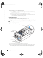
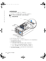
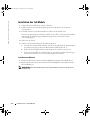
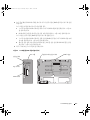
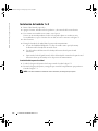
Locate the insert tab above the center filler plate. See Figure 1-1.
2
Press the insert tab and remove the center filler plate from the peripheral bay. See Figure 1-1.
NOTE: If a tape drive is not installed in your system, do not remove the top filler plate.
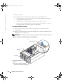
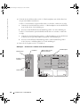
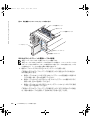
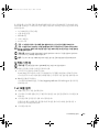
Figure 1-1. Peripheral Bay Filler Plates
3
Locate the black square on the lower filler plate. See Figure 1-1.
4
Place your right thumb on the black square, reach behind the lower filler plate, squeeze
the lower filler plate release lever, and remove the filler plate from the peripheral bay.
center filler plate
top filler plate
lower filler plate
insert tab
black square
thumbscrew
cam handle
F6590bk0.book Page 4 Tuesday, July 6, 2004 4:33 PM

Installing the 1 x 2 SCSI Module 1-5
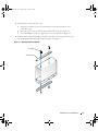
5
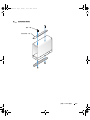
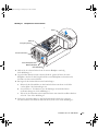
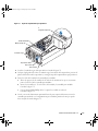
Attach the drive rails to the drive cage.
a
Align the screw holes on the drive rails with the screw holes located near slot 1
on the drive cage.
b
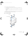
Insert the 6 x 32 screws (4) into the drive rails and drive cage. See Figure 1-2.
c
Use a #2 Phillips screwdriver to tighten the screws on each rail. See Figure 1-2.
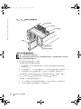
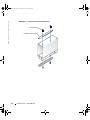
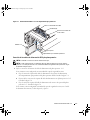
6
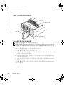
With the power connector pointing towards the top of the system, insert the drive cage
into the peripheral drive bay until it snaps into place. See Figure 1-3.
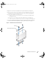
Figure 1-2. Installing the Drive Cage Rails
drive rails (2)
screws (4)
F6590bk0.book Page 5 Tuesday, July 6, 2004 4:33 PM

1-6 Installing the 1 x 2 SCSI Module
www.dell.com | support.dell.com
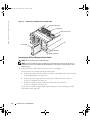
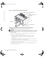
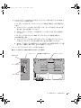
Figure 1-3. Installing the 1 x 2 Module Into the Peripheral Bay
Connecting the SCSI and Backplane Power Cables
NOTE: The 1 x 2 drive 0 functions as the boot drive.
NOTE: If your kit contains more than one SCSI cable, use the appropriate cable to connect the 1 x 2
backplane to the riser card or RAID controller. Depending on your particular configuration, the cable
length may vary.
1
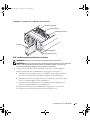
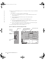
Connect the power cable harness connectors to the 1 x 2 backplane.
If your system is not configured with a tape backup unit:
a
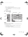
Connect the 14-pin connector on the power cable to the peripheral bay power connector
on the SCSI backplane. See Figure 1-4.
b
Connect one of the 4-pin connectors on the power cable to the power connector
on the 1 x 2 backplane. See Figure 1-4.
c
Connect the 6-pin connector on the power cable to the 6-pin connector
on the 1 x 2 backplane. See Figure 1-4.
If your system is already configured with a tape backup unit, use the existing power cable
and complete step b and step c.
1 x 2 module
peripheral drive bay
top filler plate
cable routing slot 2
cable routing slot 1
cooling fan 8
F6590bk0.book Page 6 Tuesday, July 6, 2004 4:33 PM

Installing the 1 x 2 SCSI Module 1-7
2
Connect the SCSI connector on the 1 x 2 backplane to the riser card or the optional RAID
controller card.
If your 1 x 2 module connects to the onboard riser card:
a
Connect the SCSI connector on the 1 x 2 backplane to SCSI channel A on the riser card.
See Figure 1-4.
b
Insert the SCSI cable harness into cable routing slot 1. See Figure 1-4.
If your 1 x 2 module connects to the optional RAID controller card:
a
Connect the SCSI connector on the 1 x 2 backplane to SCSI channel A (channel 0)
on the optional RAID controller card. See Figure 1-4.
b
Insert the SCSI cable into cable routing slot 2 and the cable routing slots located
at the bottom of cooling fan 8. See Figure 1-3.
3
Install the hard drives into the 1 x 2 module.
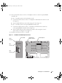
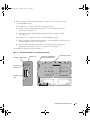
Figure 1-4. 1 x 2 Module and SCSI Backplane Connectors
peripheral bay
power connector
power
connector
6-pin
connector
SCSI
connector
1 x 2 module
SCSI backplane
F6590bk0.book Page 7 Tuesday, July 6, 2004 4:33 PM

1-8 Installing the 1 x 2 SCSI Module
www.dell.com | support.dell.com
Completing the Installation
1
Check all cable connections that may have been loosened during the procedure.
2
Arrange the cables so that they do not catch on the system cover or block the airflow
of the fans or the cooling vents.
3
Slide the drive tray to the operating position.
a
Grasp both sides of the front panel and slide the drive tray towards the back of the system
until the tray is in the operating position.
b
Rotate the drive tray release lever toward the back of the system.
c
Use a #2 Phillips screwdriver to tighten the captive screw that secures the drive tray
release handle to the chassis.
4
Close the system.
5
If you have a standalone system, reinstall the stabilizers and place the system in the upright
position (if applicable).
6
Reconnect the system to its electrical outlet and turn the system on, including any attached
peripherals.
7
Enter System Setup to ensure that the RAID or SCSI controller card is configured correctly.
You may also need to verify the correct boot order.
See your system
User’s Guide
for more information.
8
Update the system firmware.
See the Dell Support website at
support.dell.com
for the latest firmware updates.
9
Replace the bezel (if applicable).
F6590bk0.book Page 8 Tuesday, July 6, 2004 4:33 PM

www.dell.com | support.dell.com
Dell™ 系统
安装 1 x 2 SCSI 模块
F6590cbk0.book Page 1 Tuesday, July 6, 2004 4:05 PM

注、注意和警告
注:
注表示可以帮助您更好地使用计算机的重要信息。
注意:
注意表示可能会损坏硬件或导致数据丢失,并告诉您如何避免此类问题。
警告:
警告表示存在可能导致财产损失、人身伤害或死亡的潜在危险。
____________________
本文中的信息如有更改,恕不另行通知。
© 2004 Dell Inc.
。保留所有权利。
未经
Dell Inc.
书面许可,不得以任何方式进行复制。
本文件中使用的商标:
Dell
和
DELL
徽标是
Dell Inc.
的商标。
本文件中述及的其它商标和产品名称是指拥有相应商标和名称的公司或其制造的产品。
Dell Inc.
对本公司的商标和产品名称之外的其它商标和产品名称不拥有任何专利权。
2004
年
7
月
P/N F6590 Rev. A00
F6590cbk0.book Page 2 Tuesday, July 6, 2004 4:05 PM

安装 1 x 2 SCSI 模块 2-3
本说明文件介绍了如何安装
1 x 2
模块套件,使系统外围设备托架中可安装多达两个附加
1
英
寸
SCSI
硬盘驱动器。本套件包含以下项目:
•
1 x 2 SCSI
模块和背板
•
电源电缆导线
•
SCSI
电缆
•
导入滑轨
(2)
•
4 x 6-32
螺钉
警告:
执行此过程之前,请阅读《产品信息指南》中的安全说明。
警告:
只有经过培训的维修技术人员才能卸下主机盖并拆装系统内部的任何组件。有关安全预
防措施、拆装计算机内部组件以及防止静电释放的完整信息,请参阅《产品信息指南》。
注意:
为避免数据丢失,请在安装背板并更改驱动器配置之前备份硬盘驱动器上的所有数据。
注:
有关卸下和装回组件的详情,请参阅《安装与故障排除指南》。
开始之前
注意:
安装背板之前,请将 BIOS 更新为最新版本。
关闭系统以安装背板之前:
1
记下系统配置设置。
在系统设置程序中查看系统配置屏幕,并记下这些设置。有关使用系统设置程序的说
明,请参阅 《用户指南》。
2
更新
BIOS
。
请浏览
Dell
支持
Web
站点
support.ap.dell.com/china
,获得系统的最新
BIOS
版本。
安装
1 x 2
模块
1
如果需要,请卸下前挡板。
2
关闭系统 (包括连接的任何外围设备),然后断开系统与电源插座的连接。
3
如果采用机架式安装系统,则请转至骤
4
。
如果采用独立式系统,则请找一个不导电的平滑表面,卸下支脚,将系统侧立,
如图
2-1
所示。
4
打开系统。
5
将驱动器托架滑动到维护位置。
a
使用
2
号梅花槽螺丝刀,松开将驱动器托架释放手柄固定到机箱的固定螺钉。
b
朝系统的正面转动驱动器托架释放拉杆。
c
抓住前面板的两端,将驱动器托架向系统正面滑动,直到托架处于维护位置。
F6590cbk0.book Page 3 Tuesday, July 6, 2004 4:05 PM

2-4 安装 1 x 2 SCSI 模块
www.dell.com | support.dell.com
安装驱动器固定框架
1
找到中心填充板上方的插式卡舌。请参阅图
2-1
。
2
按下插式卡舌,从外围设备托架卸下中心填充板。请参阅图
2-1
。
注:
如果系统中未安装磁带驱动器,则不要卸下顶部填充板。
图
2-1.
外围设备托架填充板
3
找到下部填充板上的黑方框。请参阅图
2-1
。
4
将右手大拇指放在黑方框上,将手伸到下部填充板后面,挤压下部填充板释放拉杆,
从外围设备托架上卸下填充板。
5
将驱动器滑轨连接到驱动器托架。
a
将驱动器滑轨上的螺孔与驱动器托架上插槽
1
旁的螺孔对准。
b
将
6 x 32
螺钉
(4)
插入驱动器滑轨和驱动器托架。请参阅图
2-2
。
c
使用
2
号梅花槽螺丝刀将每个滑轨上的螺钉拧紧。请参阅图
2-2
。
6
将电源连接器指向系统顶部,将驱动器托架插入外围设备驱动器托架,
直至卡入到位。请参阅图
2-3
。
中心填充板
顶部填充板
下部填充板
插式卡舌
黑方框
指旋螺钉
凸轮手柄
F6590cbk0.book Page 4 Tuesday, July 6, 2004 4:05 PM

安装 1 x 2 SCSI 模块 2-5
图
2-2.
安装驱动器托架滑轨
驱动器滑轨(2 根)
螺钉(4 颗)
F6590cbk0.book Page 5 Tuesday, July 6, 2004 4:05 PM

2-6 安装 1 x 2 SCSI 模块
www.dell.com | support.dell.com
图
2-3.
将
1 x 2
模块装入外围设备托架
连接
SCSI
和背板电源电缆
注:
1 x 2 驱动器 0 充当引导驱动器。
注:
如果您的套件包含多根 SCSI 电缆,则使用相应的电缆将 1 x 2 背板连接到提升卡或 RAID 控
制器。电缆长度因具体配置而异。
1
将电源电缆连接器连接到
1 x 2
背板。
如果您的系统没有配置磁带备份装置:
a
将电源电缆上的
14
针连接器连接到
SCSI
背板上的外围设备托架电源连接器。
请参阅图
2-4
。
b
将电源电缆上的一个
4
针连接器连接到
1x 2
背板上的电源连接器。请参阅图
2-4
。
c
将电源电缆上的
6
针连接器连接到
1 x 2
背板上
6
针连接器。请参阅图
2-4
。
如果您的系统已经配置了磁带备份装置,则使用现有电源电缆,完成骤
b
和骤
c
。
2
将
1 x 2
背板上的
SCSI
连接器连接到提升卡或可选
RAID
控制器卡。
如果您的
1 x 2
模板连接到机载提升卡:
a
将
1 x 2
背板上的
SCSI
连接器连接到提升卡上的
SCSI
通道
A
。请参阅图
2-4
。
b
将
SCSI
电缆插入电缆布线槽口
1
。请参阅图
2-4
。
1 x 2 模块
外围设备驱动器托架
顶部填充板
电缆布线槽口 2
电缆布线槽口 1
冷却风扇 8
F6590cbk0.book Page 6 Tuesday, July 6, 2004 4:05 PM

安装 1 x 2 SCSI 模块 2-7
如果您的
1 x 2
模板连接到可选
RAID
控制器卡:
a
将
1 x 2
背板上的
SCSI
连接器连接到可选
RAID
控制器卡上的
SCSI
通道
A
(通道
0
)。请参阅图
2-4
。
b
将
SCSI
电缆插入电缆布线槽口
2
以及位于冷却风扇
8
底部的电缆布线槽口。
请参阅图
2-3
。
3
将硬盘驱动器装入
1 x 2
模块。
图
2-4. 1 x 2
模块和
SCSI
背板连接器
完成安装
1
检查在此过程中可能松动的所有电缆连接。
2
布置好所有电缆,确保它们不会卡在主机盖上,也不会阻碍风扇或通风孔的空气流动。
3
将驱动器托架滑动到操作位置。
a
抓住前面板的两端,将驱动器托架向系统背面滑动,直到托架处于操作位置。
b
朝系统的背面转动驱动器托架释放拉杆。
c
使用
2
号梅花槽螺丝刀,拧紧将驱动器托架释放手柄固定到机箱的固定螺钉。
外围设备托架电源连接器
电源连接器
6 针连接器
SCSI 连接器
1 x 2 模块
SCSI 背板
F6590cbk0.book Page 7 Tuesday, July 6, 2004 4:05 PM

2-8 安装 1 x 2 SCSI 模块
www.dell.com | support.dell.com
4
关闭系统。
5
如果采用独立式系统,则重新安装支脚并将系统直立放置 (如果适用)。
6
将系统 (包括连接的任何外围设备)重新连接至电源插座,然后开机。
7
输入系统设置,确保
RAID
或
SCSI
控制器卡配置正确无误。最好检查一下引导顺序是否
正确。
有关详情,请参阅系统的 《用户指南》。
8
更新系统固件。
有关最新的固件更新信息,请浏览
Dell
支持
Web
站点
support.ap.dell.com/china
。
9
如果需要,请装回挡板。
F6590cbk0.book Page 8 Tuesday, July 6, 2004 4:05 PM

www.dell.com | support.dell.com
Systèmes Dell™
Installation du module
SCSI 1 x 2
F6590fbk0.book Page 1 Tuesday, July 6, 2004 4:36 PM

Remarques, avis et précautions
REMARQUE : une REMARQUE indique des informations importantes qui peuvent vous aider à mieux utiliser
l'ordinateur.
AVIS : un AVIS vous avertit d'un risque de dommage matériel ou de perte de données et vous indique comment éviter
le problème.
PRÉCAUTION : une PRÉCAUTION indique un risque potentiel d'endommagement du matériel, de blessure corporelle
ou de mort.
____________________
Les informations contenues dans ce document peuvent être modifiées sans préavis.
© 2004 Dell Inc. Tous droits réservés.
La reproduction de ce document de quelque manière que ce soit sans l'autorisation écrite de Dell Inc. est strictement interdite.
Marques utilisées dans ce document : Dell et le logo DELL sont des marques de Dell Inc.
Tous les autres noms de marques et marques commerciales utilisés dans ce document se rapportent aux sociétés propriétaires des marques
et des noms de ces produits. Dell Inc. décline tout intérêt dans l'utilisation des marques déposées et des noms de marques ne lui appartenant pas.
Juillet 2004 P/N F6590 Rev. A00
F6590fbk0.book Page 2 Tuesday, July 6, 2004 4:36 PM

Installation du module SCSI 1 x 2 3-3
Ce document explique comment installer un kit de module 1 x 2 permettant d'ajouter jusqu'à
deux disques durs SCSI supplémentaires de 1 pouce dans la baie de périphériques du système.
Ce kit contient les éléments suivants :
• Module SCSI 1 x 2 et fond de panier SCSI
• Faisceau de câbles d'alimentation
• Câble(s) SCSI
• Rails de guidage (2)
• Vis 4 x 6-32
PRÉCAUTION : avant de suivre la procédure décrite dans cette section, lisez les consignes de
sécurité fournies dans le Guide d'information sur le produit et veillez à les respecter scrupuleusement.
PRÉCAUTION : seuls les techniciens de maintenance qualifiés sont habilités à retirer le capot du
système et à accéder aux composants du système. Consultez le Guide d'information sur le produit pour
obtenir des informations détaillées sur les consignes de sécurité, les interventions dans l'ordinateur
et la protection contre les décharges électrostatiques.
AVIS : pour éviter toute perte de données, sauvegardez le contenu des disques durs avant d'installer
les fonds de panier et de changer la configuration des lecteurs.
REMARQUE : consultez le Guide d'installation et de dépannage pour obtenir des instructions détaillées
sur le retrait ou le remplacement de composants.
Avant de commencer
AVIS : avant d'installer le fond de panier, vous devez mettre le BIOS à jour en installant sa version la plus
récente.
Avant d'arrêter le système pour procéder à l'installation du fond de panier :
1
Notez les paramètres de configuration du système.
Affichez les écrans du programme de configuration du système et notez les paramètres qui
y sont définis. Pour savoir comment utiliser le programme de configuration du système,
consultez le
Guide d'utilisation
.
2
Mettez le BIOS à jour.
Vous pouvez vous procurer la version la plus récente du BIOS système à partir du site Web
d'assistance technique de Dell,
support.dell.com
.
Installation du module 1 x 2
1
Retirez le cadre avant, si nécessaire.
2
Éteignez le système et les périphériques connectés, puis débranchez-le de la prise de courant.
3
Si le système est installé dans un rack, passez à l'étape 4.
S'il s'agit d'un système autonome, placez-le sur une surface plane et non conductrice, retirez
les pieds stabilisateurs et couchez le système sur le côté, comme indiqué dans la figure 3-1.
F6590fbk0.book Page 3 Tuesday, July 6, 2004 4:36 PM

3-4 Installation du module SCSI 1 x 2
www.dell.com | support.dell.com
4
Ouvrez le système.
5
Faites glisser le plateau des lecteurs pour le placer en position de maintenance.
a
À l'aide d'un tournevis cruciforme n°2, desserrez la vis imperdable qui fixe la poignée
de dégagement du plateau au châssis.
b
Faites pivoter le levier de dégagement du plateau vers l'avant du système.
c
Saisissez les deux extrémités du panneau avant et faites glisser le plateau vers l'avant
du système jusqu'à ce qu'il soit en position de maintenance.
Installation du bâti des lecteurs
1
Repérez la patte d'insertion située au-dessus de la plaque de recouvrement centrale.
Voir la figure 3-1.
2
Appuyez sur la patte d'insertion, puis retirez la plaque de recouvrement centrale de la baie
de périphériques. Voir la figure 3-1.
REMARQUE : si le système ne contient aucun lecteur de bande, ne retirez pas la plaque supérieure.
Figure 3-1. Plaques de recouvrement de la baie de périphériques
Plaque de recouvrement centrale
Plaque de recouvrement supérieure
Plaque de recouvrement
inférieure
Patte d'insertion
Carré noir
Vis
Poignée
F6590fbk0.book Page 4 Tuesday, July 6, 2004 4:36 PM

Installation du module SCSI 1 x 2 3-5
3
Repérez le carré noir situé sur la plaque de recouvrement inférieure. Voir la figure 3-1.
4
Placez votre pouce droit sur le carré, appuyez sur le levier de dégagement situé à l'arrière
de la plaque de recouvrement inférieure, puis retirez celle-ci de la baie de périphériques.
5
Fixez les rails de guidage sur le bâti des lecteurs.
a
Alignez les trous de vis des rails du lecteur avec ceux situés près de l'emplacement 1
sur le bâti des lecteurs.
b
Insérez les 4 vis 6 x 32 dans les rails et dans le bâti des lecteurs. Voir la figure 3-2.
c
Utilisez un tournevis cruciforme n°2 pour serrer les vis de chaque rail. Voir la figure 3-2.
6
Le connecteur d'alimentation faisant face à la partie supérieure du système, insérez le bâti
des lecteurs dans la baie de périphériques jusqu'à ce qu'il s'enclenche. Voir la figure 3-3.
Figure 3-2. Installation des rails sur le bâti des lecteurs
Rails de support du lecteur (2)
Vis (4)
F6590fbk0.book Page 5 Tuesday, July 6, 2004 4:36 PM

3-6 Installation du module SCSI 1 x 2
www.dell.com | support.dell.com
Figure 3-3. Installation du module 1 x 2 dans la baie de périphériques
Connexion des câbles SCSI et des câbles d'alimentation du fond de panier
REMARQUE : le lecteur 0 1 x 2 fonctionne comme lecteur d'amorçage.
REMARQUE : si le kit contient plusieurs câbles SCSI, utilisez le câble approprié pour connecter le fond
de panier 1 x 2 à la carte de montage ou au contrôleur RAID. La longueur du câble peut varier selon la
configuration adoptée.
1
Branchez les connecteurs du faisceau de câbles d'alimentation sur le fond de panier 1 x 2.
Si le système ne contient aucun lecteur de bande :
a
Branchez le connecteur à 14 broches du câble d'alimentation sur le connecteur
d'alimentation de la baie de périphériques, situé sur le fond de panier SCSI.
Voir la figure 3-4.
b
Branchez l'un des 4 connecteurs à 4 broches du câble d'alimentation sur le connecteur
d'alimentation du fond de panier 1 x 2. Voir la figure 3-4.
c
Branchez le connecteur à 6 broches du câble d'alimentation sur le connecteur à 6 broches
du fond de panier 1 x 2. Voir la figure 3-4.
Si le système ne contient aucun lecteur de bande, utilisez le câble d'alimentation existant
et effectuez l'étape b et l'étape c.
Module 1 x 2
Baie de périphériques
Plaque de recouvrement supérieure
Emplacement 2 de routage
des câbles
Emplacement 1 de routage des câbles
Ventilateur 8
F6590fbk0.book Page 6 Tuesday, July 6, 2004 4:36 PM

Installation du module SCSI 1 x 2 3-7
2
Reliez le connecteur SCSI du fond de panier 1 x 2 à la carte de montage ou à la carte
contrôleur RAID en option.
Si le module 1 x 2 se connecte sur la carte de montage intégrée :
a
Reliez le connecteur SCSI du fond de panier 1 x 2 au canal SCSI A de la carte
de montage. Voir la figure 3-4.
b
Insérez le faisceau de câbles SCSI dans l'emplacement 1 de routage de câbles.
Voir la figure 3-4.
Si le module 1 x 2 se connecte sur la carte contrôleur RAID (en option) :
a
Reliez le connecteur SCSI du fond de panier 1 x 2 au canal SCSI A (canal 0) de la carte
contrôleur RAID en option. Voir la figure 3-4.
b
Insérez le câble SCSI dans l'emplacement 2 de routage de câbles, puis dans les
emplacements de routage situés sous le ventilateur 8. Voir la figure 3-3.
3
Installez les disques durs dans le module 1 x 2.
Figure 3-4. Connecteurs du module 1 x 2 et du fond de panier SCSI
Connecteur d'alimentation
de baie de périphériques
Connecteur d'alimentation
Connecteur
à 6 broches
Connecteur
SCSI
Module 1 x 2
Fond de panier SCSI
F6590fbk0.book Page 7 Tuesday, July 6, 2004 4:36 PM

3-8 Installation du module SCSI 1 x 2
www.dell.com | support.dell.com
Finalisation de l'installation
1
Vérifiez toutes les connexions des câbles au cas où ils se seraient desserrés pendant
la procédure.
2
Disposez les câbles afin d'éviter qu'ils ne se coincent dans le capot du système ou bloquent
la circulation d'air des ventilateurs ou les orifices d'aération.
3
Faites glisser le plateau des lecteurs pour le mettre en position de fonctionnement.
a
Saisissez les deux extrémités du panneau avant et faites glisser le plateau vers l'arrière
du système jusqu'à ce qu'il soit en position de fonctionnement.
b
Faites pivoter le levier de dégagement du plateau vers l'arrière du système.
c
À l'aide d'un tournevis cruciforme n°2, resserrez la vis imperdable qui fixe la poignée
de dégagement du plateau au châssis.
4
Refermez le système.
5
Dans le cas d'un système autonome, réinstallez les pieds stabilisateurs et redressez le système,
si nécessaire.
6
Rebranchez le système sur la prise de courant et allumez-le, ainsi que tous les périphériques
connectés.
7
Accédez au programme de configuration du système et vérifiez que la carte contrôleur RAID
ou SCSI est correctement configurée. Il est possible que vous deviez aussi vérifier la séquence
de démarrage.
Consultez le
Guide d'utilisation
pour plus d'informations.
8
Mettez à jour le micro-code du système.
Consultez le site web
support.dell.com
pour obtenir les mises à jour du micro-code
les plus récentes.
9
Remettez le cadre en place, si nécessaire.
F6590fbk0.book Page 8 Tuesday, July 6, 2004 4:36 PM

www.dell.com | support.dell.com
Dell™-Systeme
Installation des
1 x 2-SCSI-Moduls
F6590gbk0.book Page 1 Tuesday, July 6, 2004 4:38 PM

Anmerkungen, Hinweise und Vorsichtshinweise
ANMERKUNG: Eine ANMERKUNG macht auf wichtige Informationen aufmerksam, die Ihnen die Arbeit
mit dem Computer erleichtern.
HINWEIS: Ein HINWEIS warnt vor möglichen Beschädigungen der Hardware oder Datenverlust und zeigt,
wie diese vermieden werden können.
VORSICHT: VORSICHT zeigt eine mögliche gefährliche Situation an, die bei Nichtbeachtung zu Sachschäden,
Körperverletzungen oder zum Tod führen könnte.
____________________
Irrtümer und technische Änderungen vorbehalten.
© 2004 Dell Inc. Alle Rechte vorbehalten.
Eine Reproduktion dieses Dokuments in jeglicher Form ohne schriftliche Genehmigung von Dell Inc. ist streng verboten.
Marken in diesem Text: Dell und das DELL-Logo sind Marken der Dell Inc.
Andere in diesem Dokument möglicherweise verwendete Marken und Handelsbezeichnungen sind unter Umständen Marken und Namen
der entsprechenden Firmen oder ihrer Produkte. Dell Inc. erhebt keinen Anspruch auf Marken und Handelsbezeichnungen mit Ausnahme
der eigenen.
Juli 2004 P/N F6590 Rev. A00
F6590gbk0.book Page 2 Tuesday, July 6, 2004 4:38 PM

Installation des 1 x 2-SCSI-Moduls 4-3
Dieses Dokument enthält eine Anleitung für die Installation eines 1x2-Modul-Einbausatzes,
der den Einbau von bis zu zwei zusätzlichen 1-Zoll-SCSI-Festplatten im Peripherieschacht Ihres
Systems ermöglicht. Das Kit enthält folgende Teile:
• 1 x 2 SCSI-Modul und Rückwandplatine
• Netzkabelbaum
• SCSI-Kabel
• Führungsschienen (2)
• 4 x 6-32-Schrauben
VORSICHT: Bevor Sie diese Arbeiten ausführen, lesen Sie zunächst die Sicherheitshinweise
im Produktinformationshandbuch.
VORSICHT: Nur ausgebildete Servicetechniker sind befugt, die Systemabdeckung zu entfernen
und Komponenten im Innern des Systems zu handhaben. Ausführliche Informationen zu den
Sicherheitsvorkehrungen beim Arbeiten im Innern des Computers und zum Schutz vor elektrischer
Entladung finden Sie im Produktinformationshandbuch.
HINWEIS: Um einem eventuellen Datenverlust vorzubeugen, sichern Sie zunächst alle Daten auf
den Laufwerken, bevor Sie die Rückwandplatinen installieren und die Laufwerkskonfiguration ändern.
ANMERKUNG: Ausführliche Erläuterungen zum Einbau oder Austausch von Komponenten finden Sie
im Installations- und Fehlerbehebungshandbuch.
Bevor Sie beginnen
HINWEIS: Bevor Sie die Rückwandplatine installieren, müssen Sie das BIOS auf die neueste Version
aktualisieren.
Bitte führen Sie folgende Maßnahmen durch, bevor Sie das System herunterfahren,
um die Rückwandplatine zu installieren:
1
Notieren Sie sich die Konfigurationseinstellungen des Systems.
Rufen Sie im System-Setup-Programm die Systemkonfigurationsbildschirme auf und
notieren Sie die angezeigten Einstellungen. Hinweise zur Verwendung des System-Setup-
Programms finden Sie im
Benutzerhandbuch
.
2
Aktualisieren Sie das BIOS.
Die aktuelle BIOS-Version für Ihr System finden Sie auf der Dell Support-Website
unter
support.dell.com
.
F6590gbk0.book Page 3 Tuesday, July 6, 2004 4:38 PM

4-4 Installation des 1 x 2-SCSI-Moduls
www.dell.com | support.dell.com
Installation des 1x2-Moduls
1
Nehmen Sie die Frontblende ab (sofern vorhanden).
2
Schalten Sie das System und die Peripheriegeräte aus, und trennen Sie das System
vom Stromnetz.
3
Wenn Ihr System in einem Rack installiert ist, fahren Sie mit Schritt 4 fort.
Wenn Sie ein Standalone-System haben, wählen Sie eine flache, nicht leitende Oberfläche,
entfernen Sie die Stabilisierungsstandfüße und legen Sie das System auf die Seite
(siehe Abbildung 4-1).
4
Öffnen Sie das System.
5
Schieben Sie den Laufwerkträger in die Wartungsposition.
a
Lösen Sie die selbstsichernde Schraube, mit der der Freigabehebel des Laufwerkträgers
am Gehäuse befestigt ist, mit einem Kreuzschlitzschraubenzieher (Nr. 2).
b
Drehen Sie den Freigabehebel des Laufwerkträgers zur Vorderseite des Systems.
c
Fassen Sie die Frontblende an beiden Seiten an und schieben Sie den Laufwerkträger
zur Systemvorderseite, bis er sich in der Wartungsposition befindet.
Installieren des Rahmens
1
Machen Sie den Einsatz über der mittleren Blindplatte ausfindig. Siehe Abbildung 4-1.
2
Drücken Sie den Einsatz herab und entfernen Sie die Blindplatte vom Peripherieschacht.
Siehe Abbildung 4-1.
ANMERKUNG: Wenn kein Bandlaufwerk in Ihrem System installiert ist, entfernen Sie die oberste
Blindplatte nicht.
F6590gbk0.book Page 4 Tuesday, July 6, 2004 4:38 PM

Installation des 1 x 2-SCSI-Moduls 4-5
Abbildung 4-1. Blindplatten der externen Schächte
3
Machen Sie das schwarze Rechteck auf der unteren Blindplatte ausfindig.
Siehe Abbildung 4-1.
4
Legen Sie Ihren Daumen auf das schwarze Rechteck, greifen Sie hinter die untere
Blindplatte, drücken Sie den Freigabehebel der unteren Blindplatte und entfernen Sie
die Platte aus dem externen Schacht.
5
Befestigen Sie die Laufwerkschienen am Laufwerkträger.
a
Richten Sie die Schraublöcher an den Laufwerkschienen mit denen in der Nähe
von Steckplatz 1 des Laufwerkträgers aus.
b
Setzen Sie die 6 x 32-Schrauben (4) in die Öffnungen an Laufwerkschienen
und Laufwerkträger ein. Siehe Abbildung 4-2.
c
Ziehen Sie die Schrauben an den Laufwerkschienen mit einem Kreuzschlitzschrauben-
zieher Nr. 2 fest. Siehe Abbildung 4-2.
6
Stecken Sie den Laufwerkträger in den Peripherielaufwerksschacht, bis er einrastet.
Der Netzanschluss muss dabei zur Oberseite des Systems weisen. Siehe Abbildung 4-3.
Mittlere Blindplatte
Obere Blindplatte
Untere Blindplatte
Einsatz
Schwarzes Rechteck
Halterung
Verriegelungshebel
F6590gbk0.book Page 5 Tuesday, July 6, 2004 4:38 PM

4-6 Installation des 1 x 2-SCSI-Moduls
www.dell.com | support.dell.com
Abbildung 4-2. Installieren der Laufwerkträgerschienen
Laufwerksschienen (2)
Schrauben (4)
F6590gbk0.book Page 6 Tuesday, July 6, 2004 4:38 PM

Installation des 1 x 2-SCSI-Moduls 4-7
Abbildung 4-3. Installieren des 1 x 2-Moduls im externen Schacht
SCSI- und Rückwandplatinen-Netzkabel anschließen
ANMERKUNG: Laufwerk 0 des 1 x 2-Moduls übernimmt die Rolle des Startlaufwerks.
ANMERKUNG: Wenn Ihr Einbausatz mehrere SCSI-Kabel enthält, verwenden Sie das passende Kabel,
um die 1 x 2-Rückwandplatine mit der Riser-Karte bzw. dem RAID-Controller zu verbinden. Die
erforderliche Kabellänge ist abhängig von Ihrer spezifischen Konfiguration.
1
Verbinden Sie die Anschlüsse des Netzkabelbaums mit der 1 x 2-Rückwandplatine.
Falls Ihr System nicht über ein Bandlaufwerk verfügt, gehen sie wie folgt vor:
a
Verbinden Sie den 14-poligen Stecker des Netzkabels mit dem Netzanschluss für
den externen Schacht auf der SCSI-Rückwandplatine. Siehe Abbildung 4-4.
b
Verbinden Sie einen der 4-poligen Stecker des Netzkabels mit dem Netzanschluss
an der 1 x 2-Rückwandplatine. Siehe Abbildung 4-4.
c
Verbinden Sie den 6-poligen Stecker des Netzkabels mit dem 6-poligen Stecker
auf der 1 x 2-Rückwandplatine. Siehe Abbildung 4-4.
Wenn Ihr System bereits mit einem Bandlaufwerk ausgerüstet ist, verwenden Sie
das vorhandene Netzkabel und führen Sie Schritt b und Schritt c aus.
1 x 2-Modul
Externer Laufwerkschacht
Obere Blindplatte
Kabelführungsschlitz 2
Kabelführungsschlitz 1
Kühlungslüfter 8
F6590gbk0.book Page 7 Tuesday, July 6, 2004 4:38 PM

4-8 Installation des 1 x 2-SCSI-Moduls
www.dell.com | support.dell.com
2
Verbinden Sie den SCSI-Anschluss auf der 1 x 2-Rückwandplatine mit der Riser-Karte bzw.
der optionalen RAID-Controllerkarte.
Um Ihr 1 x 2-Modul mit der eingebauten Riser-Karte zu verbinden, verfahren Sie wie folgt:
a
Verbinden Sie den SCSI-Anschluss auf der 1 x 2-Rückwandplatine mit dem SCSI-Kanal
A auf der Riser-Karte. Siehe Abbildung 4-4.
b
Passen Sie den SCSI-Kabelbaum in Kabelführungsschlitz 1 ein. Siehe Abbildung 4-4.
Um Ihr 1 x 2-Modul mit der optionalen RAID-Controllerkarte zu verbinden, verfahren Sie
wie folgt:
a
Verbinden Sie den SCSI-Anschluss auf der 1 x 2-Rückwandplatine mit dem SCSI-Kanal
A (Kanal 0) auf der optionalen RAID-Controllerkarte. Siehe Abbildung 4-4.
b
Passen Sie das SCSI-Kabel in Kabelführungsschlitz 2 und die Kabelführungsschlitze
an der Unterseite von Kühlungslüfter 8 ein. Siehe Abbildung 4-3.
3
Bauen Sie die Festplatten in das 1 x 2-Modul ein.
Abbildung 4-4. Anschlüsse des 1 x 2-Moduls und der SCSI-Rückwandplatine
Netzanschluss für den
externen Schacht
Netzanschluss
6-poliger
Anschluss
SCSI-Anschluss
1 x 2-Modul
SCSI-Backplane
F6590gbk0.book Page 8 Tuesday, July 6, 2004 4:38 PM

Installation des 1 x 2-SCSI-Moduls 4-9
Abschließen der Installation
1
Überprüfen Sie alle Kabelverbindungen, die während der Prozedur gelöst wurden.
2
Ordnen Sie die Kabel so an, dass sie nicht in der Systemabdeckung eingeklemmt werden
können oder die Lüfter oder Lüftungsöffnungen versperren.
3
Schieben Sie den Laufwerkträger in die Betriebsposition.
a
Fassen Sie die Frontblende an beiden Seiten an und schieben Sie den Laufwerkträger
zur Systemrückseite, bis er sich in der Betriebsposition befindet.
b
Drehen Sie den Freigabehebel des Laufwerkträgers zur Rückseite des Systems.
c
Ziehen Sie die selbstsichernde Schraube, mit der der Freigabehebel des Laufwerkträgers
am Gehäuse befestigt ist, mit einem Kreuzschlitzschraubenzieher (Nr. 2) fest.
4
Schließen Sie das System.
5
Falls Sie ein Standalone-System haben, bringen Sie ggf. die Stabilisierungsstandfüße wieder
an, und stellen Sie das System in aufrechter Position auf.
6
Schließen Sie das System wieder an das Stromnetz an, und schalten Sie das System
und alle angeschlossenen Peripheriegeräte ein.
7
Rufen Sie das System-Setup auf, um sich zu vergewissern, dass die RAID- bzw. SCSI-
Controllerkarte korrekt konfiguriert wurde. Überprüfen Sie ggf. auch die Startreihenfolge.
Weitere Informationen hierzu finden Sie im
Benutzerhandbuch
Ihres Systems.
8
Aktualisieren Sie die Firmware des Systems.
Eine Liste der aktuellen Firmware-Updates finden Sie auf der Dell Support-Website
unter
support.euro.dell.com
.
9
Bringen Sie gegebenenfalls die Blende wieder an.
F6590gbk0.book Page 9 Tuesday, July 6, 2004 4:38 PM

4-10 Installation des 1 x 2-SCSI-Moduls
www.dell.com | support.dell.com
F6590gbk0.book Page 10 Tuesday, July 6, 2004 4:38 PM

www.dell.com | support.dell.com
Dell
™
システム
1
×
2 SCSI
モジュールの取り付け
F6590jbk0.book Page 1 Tuesday, July 6, 2004 4:47 PM

メモ、注意、警告
メモ: 操作上、知っておくと便利な情報が記載されています。
注意: ハードウェアの損傷やデータの損失の可能性があることを示し、その危険を回避するための方法を
説明しています。
警告: 物的損害、けが、または死亡の原因となる可能性があることを示します。
____________________
ここに記載されている内容は予告なく変更されることがあります。
© 2004 すべての著作権は Dell Inc. にあります。
Dell Inc. の書面による許可のない複製は、いかなる形態においても厳重に禁じられています。
本書で使用されている商標について: Dell および DELL ロゴは Dell Inc. の商標です。
本書では、必要に応じて上記記載以外の商標や会社名が使用されている場合がありますが、 これらの商標や会社名は、
一切 Dell Inc. に所属するものではありません。
2004 年 7 月 P/N F6590 Rev. A00
F6590jbk0.book Page 2 Tuesday, July 6, 2004 4:47 PM

1 × 2 SCSI モジュールの取り付け 5-3
本書では
1
×
2
モジュールキットを取り付けて、システムの周辺機器ベイに最大
2
つ
の
1
イ
ンチ
SCSI
ハードドライブを追加できるようにする手順について説明します
。
このキットの
内容は次のとおりです。
•
1
×
2 SCSI
モジュールおよびバックプレーン
•
電源ケーブルハーネス
•
SCSI
ケーブル
•
ガイドレール(
2
)
•
4
×
6-32
ネジ
警告: この手順を行う前に、『製品情報ガイド』の安全にお使いいただくための注意をお読
みください。
警告: システムのカバーを取り外して、内部の部品に手を触れる作業は、訓練を受けたサー
ビス技術者の方だけが行ってください。 安全上の注意、コンピュータ内部の作業、および静
電気障害への対処の詳細については、『製品情報ガイド』を参照してください。
注意: データの損失を防ぐために、バックプレーンの取り付けおよびドライブ構成の変更を行
う前に、ハードドライブにあるすべてのデータをバックアップしてください。
メモ: コンポーネントの取り外しと取り付けの詳しい手順は、『インストール&トラブル
シューティング』を参照してください。
準備作業
注意: バックプレーンを取り付ける前に、BIOS を最新バージョンにアップデートします。
システムをシャットダウンしてバックプレーンを取り付ける前に、次の手順を実行します。
1
システムの設定情報を記録します。
セットアップユーティリティのシステム設定情報画面を表示し、設定情報を記録しま
す。
セットアップユーティリティの使い方については、『ユーザーズガイド』を参照し
てください。
2
BIOS
をアップデートします。
お使いのシステムに対応した
BIOS
の最新バージョンについては、デルサポートサイ
ト
support.dell.com
を参照してください。
1 × 2 モジュールの取り付け
1
前面ベゼルを取り付けている場合は、ベゼルを取り外します。
2
システムの電源を切り、システムに接続されているすべての周辺機器の電源を切って、
電源コンセントから抜きます。
3
お使いのシステムがラックに取り付けてある場合は、手順
4
に進みます。
スタンドアロンシステムの場合は、非伝導性の水平な面を探して安定板を取り外し、
図
5-1
に示すようにシステムを横に倒します。
F6590jbk0.book Page 3 Tuesday, July 6, 2004 4:47 PM

5-4 1 × 2 SCSI モジュールの取り付け
www.dell.com | support.dell.com
4
システムカバーを開きます。
5
ドライブトレイをスライドさせ、メンテナンスの位置にします。
a
2
番のプラスドライバを使って、ドライブトレイリリースハンドルをシャーシに固
定しているネジを緩めます。
b
ドライブトレイのリリースレバーをシステムの正面方向に動かします。
c
正面パネルの両端をつかんでドライブトレイをシステムの正面方向にスライドさ
せ、メンテナンスの位置にします。
ドライブケージの取り付け
1
中段フィラープレートの上部にある挿入タブの位置を確認します。
図
5-1
を参照してください。
2
挿入タブを押して、中段フィラープレートを周辺機器ベイから取り外します。
図
5-1
を参照してください。
メモ: システムにテープドライブを取り付けていない場合は、上段フィラープレートを取り
外さないでください。
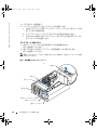
図 5-1 周辺機器ベイのフィラープレート
中段フィラープレート
上段フィラープレート
下段フィラープレート
挿入タブ
黒い正方形
蝶ネジ
カムハンドル
F6590jbk0.book Page 4 Tuesday, July 6, 2004 4:47 PM

1 × 2 SCSI モジュールの取り付け 5-5
3
下段フィラープレートにある黒い正方形の位置を確認します。
図
5-1
を参照してくだ
さい。
4
黒い正方形に右手の親指を当て、下段フィラープレートの裏側に手を伸ばして下段フィ
ラープレートのリリースレバーを押し、フィラープレートを周辺機器ベイから取り外し
ます。
5
ドライブレールをドライブケージに取り付けます。
a
ドライブレールのネジ穴と、ドライブケージのスロット
1
の近くにあるネジ穴を合
わせます。
b
6 x 32
ネジ(
4
)をドライブレールとドライブケージに挿入します。
図
5-2
を参照してください。
c
#2
プラスドライバを使って、各レールのネジを締めます。
図
5-2
を参照してください。
6
電源コネクタがシステム上部を指す向きにして、ドライブケージを周辺機器ドライブベ
イに挿入し、所定の位置にカチッと固定します。
図
5-3
を参照してください。
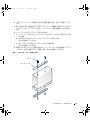
図 5-2 ドライブケージレールの取り付け
ドライブレール(2)
ネジ(4)
F6590jbk0.book Page 5 Tuesday, July 6, 2004 4:47 PM

5-6 1 × 2 SCSI モジュールの取り付け
www.dell.com | support.dell.com
図 5-3 周辺機器ベイへの 1 × 2 モジュールの取り付け
SCSI およびバックプレーンの電源ケーブルの接続
メモ: 1 × 2 ドライブ 0 は、起動ドライブとして機能します。
メモ: キットに 2 本以上の SCSI ケーブルが含まれている場合は、1 × 2 バックプレーンをラ
イザーカードまたは RAID コントローラに接続するのに適したケーブルを使用します。 システ
ムの設定により、ケーブルの長さが異なる場合があります。
1
電源ケーブルハーネスコネクタを
1
×
2
バックプレーンに接続します。
ご使用のシステムがテープバックアップ装置を使うように設定されていない場合は、
次の手順を実行します。
a
電源ケーブルの
14
ピンコネクタを、
SCSI
バックプレーンの周辺機器ベイ電源コネ
クタに接続します。
図
5-4
を参照してください。
b
電源ケーブルの
4
ピンコネクタの
1
つを、
1
×
2
バックプレーンの電源コネクタに
接続します。
図
5-4
を参照してください。
c
電源ケーブルの
6
ピンコネクタを、
1
×
2
バックプレーンの
6
ピンコネクタに接続
します。
図
5-4
を参照してください。
ご使用のシステムがテープバックアップ装置を使うようにすでに設定されている場合
は、既存の電源ケーブルを使用して
手順
b
および
手順
c
を完了します。
1 × 2 モジュール
周辺機器ドライブベイ
上段のフィラープレート
ケーブル配線スロット 2
ケーブル配線スロット 1
冷却ファン 8
F6590jbk0.book Page 6 Tuesday, July 6, 2004 4:47 PM

1 × 2 SCSI モジュールの取り付け 5-7
2
1
×
2
バックプレーンの
SCSI
コネクタを、ライザーカードまたはオプションの
RAID
コ
ントローラカードに接続します。
1
×
2
モジュールをオンボードのライザーカードに接続する場合は、次の手順を実行
します。
a
1
×
2
バックプレーンの
SCSI
コネクタを、ライザーカードの
SCSI
チャネル
A
に接
続します。
図
5-4
を参照してください。
b
SCSI
ケーブルハーネスをケーブル配線スロット
1
に挿入します。
図
5-4
を参照し
てください。
1
×
2
モジュールをオプションの
RAID
コントローラカードに接続する場合は、
次の手順を実行します。
a
1
×
2
バックプレーンの
SCSI
コネクタを、オプションの
RAID
コントローラカード
の
SCSI
チャネル
A
(チャネル
0
)に接続します。
図
5-4
を参照してください。
b
SCSI
ケーブルをケーブル配線スロット
2
と、冷却ファン
8
の底部にあるケーブル配
線スロット(複数)に挿入します。
図
5-3
を参照してください。
3
ハードドライブを
1
×
2
モジュールに取り付けます。
図 5-4 1 × 2 モジュールおよび SCSI バックプレーンコネクタ
周辺機器ベイ電源コネクタ
電源コネクタ
6 ピンコネクタ
SCSI コネクタ
1 × 2 モジュール
SCSI バックプレーン
F6590jbk0.book Page 7 Tuesday, July 6, 2004 4:47 PM

5-8 1 × 2 SCSI モジュールの取り付け
www.dell.com | support.dell.com
取り付けの完了
1
作業中に緩んだ可能性のあるすべてのケーブルの接続を確認します。
2
ケーブルがシステムカバーに挟まったり、ファンや冷却通気孔の空気の流れを妨げたり
しないように整えます。
3
ドライブトレイをスライドさせ、動作位置にします。
a
正面パネルの両端をつかんでドライブトレイをシステムの背面方向にスライドさ
せ、動作位置にします。
b
ドライブトレイのリリースレバーをシステムの背面方向に動かします。
c
2
番のプラスドライバを使って、ドライブトレイリリースハンドルをシャーシに固
定するネジを締めます。
4
システムカバーを閉じます。
5
スタンドアロンシステムの場合は、安定板を取り付け、システムを垂直の状態にして置
きます(該当する場合)。
6
システムおよびシステムに接続されている周辺機器を電源コンセントに接続し、電源を
入れます。
7
セットアップユーティリティを起動して、
RAID
または
SCSI
コントローラカードが正し
く設定されていることを確認します。
正しい起動順序も確認する必要があるかもしれ
ません。
詳細については、システムの『ユーザーズガイド』を参照してください。
8
システムのファームウェアをアップデートします。
ファームウェアのアップデート版については、デルサポートサイト
support.dell.com
を参照してください。
9
ベゼルを取り外した場合は、ベゼルを取り付けます。
F6590jbk0.book Page 8 Tuesday, July 6, 2004 4:47 PM

www.dell.com | support.dell.com
Dell™ 시스템
1 x 2 SCSI 모듈 설치
F6590kbk0.book Page 1 Monday, July 5, 2004 3:21 PM

주 , 주의사항 및 주의
참고: 주는 컴퓨터를 보다 효율적으로 사용할 수 있는 중요 정보를 제공합니다.
주의사항: 주의사항은 하드웨어의 손상 또는 데이터 유실 위험을 설명하며, 이러한 문제를 방지할 수 있는 방
법을 알려줍니다.
주의: 주의는 위험한 상황, 심각한 부상 또는 사망할 우려가 있음을 알려줍니다.
____________________
본 설명서에 수록된 정보는 사전 통보 없이 변경될 수 있습니다.
© 2004 Dell Inc. All rights reserved.
Dell Inc.의 사전 승인 없이 어떠한 경우에도 무단 복제하는 것을 엄격히 금합니다.
본 설명서에 사용된 상표: Dell 및 DELL 로고는 Dell Inc.의 상표입니다.
본 설명서에서 특정 회사의 표시나 제품 이름을 지칭하기 위해 기타 상표나 상호를 사용할 수도 있습니다.
Dell Inc.은 자사가 소유하고 있는 것 이외에 기타 모든 등록 상표 및 상표 이름에 대한 어떠한 소유권도 없습니다.
2004 년 7 월 P/N F6590 Rev. A00
F6590kbk0.book Page 2 Monday, July 5, 2004 3:21 PM

1 x 2 SCSI 모듈 설치 6-3
본
설명서에는
시스템의
주변장치
베이에
최대
2
개의
추가
1
인치
SCSI
하드
드라이브를
지원
하기
위해
추가하는
1 x 2
모듈
키트
설치
지침을
다룹니다
.
키트에는
다음과
같은
항목이
포함
되어
있습니다
:
• 1 x 2 SCSI
모듈
및
후면
패널
•
전원
케이블
연결
•SCSI
케이블
•
가이드
레일
(2)
• 4 x 6-32
나사
주의 : 이 과정을 수행하기 전에 제품 정보 설명서에 있는 안전 지침 사항을 읽어보십시오 .
주의 : 숙련된 서비스 기술자만 시스템 덮개를 분리하고 시스템 내부의 구성요소에 액세스해야
합니다 . 안전 지침 , 컴퓨터 내부 작업 및 정전기 방전 보호에 대한 자세한 내용은 시스템 정보 설
명서를 참조하십시오 .
주의사항: 데이타 손실을 방지하려면 후면판을 설치하고 드라이브 구성을 변경하기 전에 하드
드라이브의 모든 데이타를 백업해두십시오.
참고: 구성 요소 제거 및 교체에 대한 세부 지침은 설치 및 문제 해결 설명서 를 참조하십시오.
시작하기 전에
주의사항: 후면 패널을 설치하기 전에 BIOS를 최신 버전으로 갱신하십시오.
후면
패널을
설치하기
위해
시스템을
종료하기
전에
:
1
시스템
구성
설정값을
기록해
두십시오
.
System Setup
프로그램의
시스템
구성
화면에서
이
설정값을
확인하고
기록해
두십시오
.
시스템
설치
프로그램
사용에
관한
자세한
내용은
시스템의
사용
설명서를
참조하십시오
.
2
BIOS
를
업데이트하십시오
.
시스템의
최신
BIOS
버전을
구하려면
support.ap.dell.com
에서
Dell Support
웹
사이트를
참조하십시오
.
1 x 2 모듈 설치
1
배젤이
있는
경우
,
이를
분리하십시오
.
2
시스템과
시스템에
연결된
모든
주변장치의
전원을
끄고
전원
콘센트에서
시스템을
분리
하십시오
.
3
시스템을
랙에
설치한
경우
단계
4
로
이동하십시오
.
독립형
시스템을
사용할
경우
평평한
비전도
표면을
찾아
고정
다리를
분리한
다음
그
림
6-1
처럼
시스템을
눕히십시오
.
4
시스템을
여십시오
.
F6590kbk0.book Page 3 Monday, July 5, 2004 3:21 PM

6-4 1 x 2 SCSI 모듈 설치
www.dell.com | support.dell.com
5
드라이브
트레이를
유지보수
위치로
미십시오
.
a
#2 Phillips
드라이버를
사용하여
드라이브
트레이
분리
핸들을
섀시에
고정하는
나사
를
푸십시오
.
b
드라이브
트레이
분리
레버를
시스템
전면을
향해
돌리십시오
.
c
전면
패널의
양
쪽을
잡고
드라이브
트레이가
유지보수
위치가
될
때까지
시스템
전면
을
향해
드라이브
트레이를
미십시오
.
드라이브 케이지 설치
1
중앙
필러
플레이트
위에
있는
삽입기
탭을
찾으십시오
.
그림
6-1
을
참조하십시오
.
2
삽입기
탭을
눌러
중앙
필러
플레이트를
주변장치
베이에서
분리하십시오
.
그림
6-1
을
참
조하십시오
.
참고:
시스템에
테이프
드라이브를
설치하지
않은
경우
상단
필러
플레이트를
분리하지
마십시오
.
그림 6-1. 주변장치 베이 필러 플레이트
3
하단
필러
플레이트에서
검은색
사각형을
찾으십시오
.
그림
6-1
을
참조하십시오
.
4
오른손
엄지
손가락을
검은색
사각형에
대고
하단
필러
플레이트
뒤쪽에
닿은
다음
,
하단
필러
플레이트
분리
레버를
눌러
주변장치
베이에서
필러
플레이트를
분리하십시오
.
중앙 필러 플레이트
상단 필러 플레이트
하단 필러 플레이트
삽입기 탭
검은색 사각형
손잡이 나사
cam 핸들
F6590kbk0.book Page 4 Monday, July 5, 2004 3:21 PM

1 x 2 SCSI 모듈 설치 6-5
5
드라이브
레일을
드라이브
케이지에
연결하십시오
.
a
나사
구멍이
드라이브
케이지의
슬롯
1
근처에
위치하도록
드라이브
레일의
나사
구
멍을
맞추십시오
.
b
6 x 32
나사
(4)
를
드라이브
레일과
드라이브
케이지에
삽입하십시오
.
그림
6-2
을
참조
하십시오
.
c
#2 Phillips
드라이버를
사용하여
각
레일의
나사를
조이십시오
.
그림
6-2
을
참조하십
시오
.
6
전원
커넥터가
시스템
상단을
향하도록
하여
드라이브
케이지가
단단히
맞물릴
때까지
주
변장치
베이에
삽입하십시오
.
그림
6-3
을
참조하십시오
.
그림 6-2. 드라이브 케이지 레일 설치
드라이브 레일 (2)
나사 (4)
F6590kbk0.book Page 5 Monday, July 5, 2004 3:21 PM

6-6 1 x 2 SCSI 모듈 설치
www.dell.com | support.dell.com
그림 6-3. 1 x 2 모듈을 주변장치 베이에 설치
SCSI 및 후면 패널 전원 케이블 연결
참고: 1 x 2 드라이브 0이 부트 드라이브 기능을 합니다.
참고: 키트에 둘 이상의 SCSI 케이블이 포함된 경우 해당하는 케이블을 사용하여 1 x 2 후면 패널
을 라이저 카드나 RAID 컨트롤러에 연결하십시오. 특정 구성에 따라 케이블 길이가 다를 수 있습
니다.
1
전원
케이블
연결
커넥터를
1 x 2
후면
패널에
연결하십시오
.
시스템에
테이프
백업
장치가
구성되지
않은
경우
:
a
전원
케이블의
14
핀
커넥터를
SCSI
후면
패널의
주변장치
베이
전원
커넥터에
연결하
십시오
.
그림
6-4
을
참조하십시오
.
b
전원
케이블의
4
핀
커넥터
중
하나를
1x 2
후면
패널의
전원
커넥터에
연결하십시오
.
그림
6-4
을
참조하십시오
.
c
전원
케이블의
6
핀
커넥터를
1 x 2
후면
패널의
6
핀
커넥터에
연결하십시오
.
그림
6-4
을
참조하십시오
.
시스템에
테이프
백업
장치가
구성된
경우
기존
전원
케이블을
사용하고
단계
b
및
단계
c
를
수행하십시오
.
1 x 2 모듈
주변장치 드라이브 베이
상단 필러 플레이트
케이블 전송 슬롯 2
케이블 전송 슬롯 1
냉각 팬 8
F6590kbk0.book Page 6 Monday, July 5, 2004 3:21 PM

1 x 2 SCSI 모듈 설치 6-7
2
1 x 2
후면
패널의
SCSI
커넥터를
라이저
카드나
선택
사양인
RAID
컨트롤러
카드에
연결
하십시오
.
1 x 2
모듈을
내장형
라이저
카드에
연결한
경우
:
a
1 x 2
후면
패널의
SCSI
커넥터를
라이저
카드의
SCSI
채널에
연결하십시오
.
그림
6-4
를
참조하십시오
.
b
SCSI
케이블
연결을
케이블
전송
슬롯
1
에
삽입하십시오
.
그림
6-4
를
참조하십시오
.
1 x 2
모듈을
선택
사양인
RAID
컨트롤러
카드에
연결한
경우
:
a
1 x 2
후면
패널의
SCSI
커넥터를
선택
사양인
RAID
컨트롤러
카드의
SCSI
채널
A(
채
널
0)
에
연결하십시오
.
그림
6-4
를
참조하십시오
.
b
케이블
전송
슬롯
2
와
냉각팬
8
하단에
있는
케이블
전송
슬롯에
SCSI
케이블을
삽입
하십시오
.
그림
6-3
을
참조하십시오
.
3
하드
드라이브를
1 x 2
모듈에
설치하십시오
.
그림 6-4. 1 x 2 모듈 및 SCSI 후면 패널 커넥터
주변장치 베이 전원 커넥터
전원 커넥터
6 핀 커넥터
SCSI 커넥터
1 x 2 모듈
SCSI 후면판
F6590kbk0.book Page 7 Monday, July 5, 2004 3:21 PM

6-8 1 x 2 SCSI 모듈 설치
www.dell.com | support.dell.com
설치 완료
1
이
과정을
수행하는
동안
케이블
연결이
느슨해졌을
경우에
대비하여
케이블을
모두
점검
해보십시오
.
2
케이블이
시스템
덮개에
걸리거나
팬
또는
공기
환기
장치
입구를
막지
않도록
잘
정돈하
십시오
.
3
드라이브
트레이를
작동
위치로
미십시오
.
a
전면
패널의
양
쪽을
잡고
드라이브
트레이가
작동
위치가
될
때까지
시스템
후면을
향해
드라이브
트레이를
미십시오
.
b
드라이브
트레이
분리
레버를
시스템
후면을
향해
돌리십시오
.
c
#2 Phillips
드라이버를
사용하여
드라이브
트레이
분리
핸들을
섀시에
고정하는
나사
를
조이십시오
.
4
시스템을
닫으십시오
.
5
독립형
시스템을
사용할
경우
고정
다리를
다시
설치하고
시스템을
똑바로
세워
놓으십시
오
(
해당할
경우
).
6
시스템을
전원
콘센트에
다시
연결하고
시스템과
시스템에
연결된
주변장치의
전원을
모
두
켜십시오
.
7
시스템
설치
프로그램을
실행하여
RAID
또는
SCSI
컨트롤러
카드가
제대로
구성되었는
지
확인하십시오
.
올바른
부팅
순서를
확인해야
할
수도
있습니다
.
자세한
내용은
시스템
사용
설명서를
참조하십시오
.
8
시스템
펌웨어를
업데이트하십시오
.
최신
펌웨어
업데이트는
support.ap.dell.com
에서
Dell Support
웹
사이트를
참조하십시오
.
9
배젤이
있는
경우
,
교체하십시오
.
F6590kbk0.book Page 8 Monday, July 5, 2004 3:21 PM

www.dell.com | support.dell.com
Sistemas Dell™
Instalación del módulo
SCSI 1 x 2
F6590sbk0.book Page 1 Tuesday, July 6, 2004 4:55 PM

Notas, avisos y precauciones
NOTA: una NOTA proporciona información importante que le ayudará a utilizar mejor el ordenador.
AVISO: un AVISO indica un posible daño en el hardware o la pérdida de datos, e informa de cómo evitar el problema.
PRECAUCIÓN: un mensaje de PRECAUCIÓN indica el riesgo de daños materiales, lesiones corporales o incluso
la muerte.
____________________
La información contenida en este documento puede modificarse sin previo aviso.
© 2004 Dell Inc. Reservados todos los derechos.
Queda estrictamente prohibida la reproducción de este documento en cualquier forma sin la autorización por escrito de Dell Inc.
Marcas comerciales que aparecen en el texto: Dell y el logotipo de DELL son marcas comerciales de Dell Inc.
Otras marcas y otros nombres comerciales pueden utilizarse en este documento para hacer referencia a las entidades que los poseen
o a sus productos. Dell Inc. renuncia a cualquier interés sobre la propiedad de marcas y nombres comerciales que no sean los suyos.
Julio de 2004 P/N F6590 Rev. A00
F6590sbk0.book Page 2 Tuesday, July 6, 2004 4:55 PM

Instalación del módulo SCSI 1 x 2 7-3
Este documento proporciona las instrucciones necesarias para instalar un kit de módulo 1 x 2 con el
fin de aumentar la capacidad hasta dos unidades de disco duro SCSI adicionales de una pulgada en
el compartimiento para periféricos del sistema. Este kit contiene los siguientes componentes:
• Plano posterior y módulo SCSI 1 x 2
• Sistema de cables de alimentación
• Cables SCSI
• Rieles de guía (2)
• Tornillos 4 x 6-32
PRECAUCIÓN: antes de realizar este procedimiento, lea las instrucciones de seguridad incluidas
en la Guía de información del producto.
PRECAUCIÓN: los técnicos de servicio especializados son las únicas personas autorizadas para
retirar las cubiertas y acceder a los componentes internos del sistema. Consulte la Guía de
información del producto para obtener información completa sobre las precauciones de seguridad,
la manipulación de las piezas internas del ordenador y la protección contra descargas electrostáticas.
AVISO: para evitar la pérdida de datos, realice una copia de seguridad de todos los datos de las
unidades de disco duro antes de instalar los planos posteriores y cambiar la configuración de la unidad.
NOTA: consulte la Guía de instalación y solución de problemas para obtener instrucciones detalladas
sobre la extracción y la colocación de componentes.
Antes de empezar
AVISO: antes de instalar el plano posterior, actualice el BIOS a la versión más reciente.
Antes de apagar el sistema para instalar el plano posterior:
1
Grabe los valores de configuración del sistema.
Revise las pantallas de configuración del sistema en el programa de configuración del sistema
y registre todos estos valores. Para obtener instrucciones sobre cómo utilizar el programa de
configuración del sistema, consulte la
Guía del usuario
.
2
Actualice el BIOS.
Consulte la página Web de soporte de Dell en la dirección
support.dell.com
para obtener
la última versión del BIOS para su sistema.
F6590sbk0.book Page 3 Tuesday, July 6, 2004 4:55 PM

7-4 Instalación del módulo SCSI 1 x 2
www.dell.com | support.dell.com
Instalación del módulo 1 x 2
1
Retire el bisel frontal (si procede).
2
Apague el sistema, incluidos todos los periféricos, y desconéctelo de la toma eléctrica.
3
Si su sistema está instalado en un estante, vaya al paso 4.
Si tiene un sistema independiente, localice una superficie plana no conductora, retire
los estabilizadores y apoye el sistema sobre un lado, tal como se muestra en la figura 7-1.
4
Abra el sistema.
5
Extraiga la bandeja de la unidad hasta la posición de mantenimiento.
a
Con un destornillador Phillips del nº 2, afloje el tornillo cautivo que fija la manija
de liberación de la bandeja del sistema al chasis.
b
Tire de la palanca de liberación de la bandeja del sistema hacia la parte frontal
del sistema.
c
Sujete ambos lados del panel frontal y deslice la bandeja del sistema hacia la parte frontal
del sistema hasta que la bandeja esté en la posición de mantenimiento.
Instalación del soporte de unidad
1
Localice la lengüeta de fijación sobre la tapa central. Consulte la figura 7-1.
2
Presione la lengüeta de fijación y extraiga la tapa central del compartimiento para periféricos.
Consulte la figura 7-1.
NOTA: si no tiene instalada una unidad de cinta en el sistema, no extraiga la tapa superior.
F6590sbk0.book Page 4 Tuesday, July 6, 2004 4:55 PM

Instalación del módulo SCSI 1 x 2 7-5
Figura 7-1. Tapas del compartimiento para periféricos
3
Localice el cuadrado negro de la tapa inferior. Consulte la figura 7-1.
4
Coloque el pulgar derecho sobre el cuadrado negro, hasta detrás de la tapa inferior, presione la
palanca de liberación de la tapa inferior y extraiga la tapa del compartimiento para periféricos.
5
Encaje los rieles de la unidad en la canastilla para unidades.
a
Alinee los agujeros de los tornillos de los rieles de la unidad con los que se encuentran
junto a la ranura 1 de la canastilla para unidades.
b
Inserte los 4 tornillos 6 x 32 en los rieles de la unidad y la canastilla para unidades.
Consulte la figura 7-2.
c
Con un destornillador Phillips del nº 2, apriete los tornillos en cada riel.
Consulte la figura 7-2.
6
Con el conector de alimentación apuntando hacia la parte superior del sistema, inserte la
canastilla para unidades en el compartimiento para unidades periféricas hasta que quede
bien encajada. Consulte la figura 7-3.
Tapa central
Tapa superior
Tapa inferior
Lengüeta de fijación
Cuadrado negro
Tornillo moleteado
Manija de fijación
F6590sbk0.book Page 5 Tuesday, July 6, 2004 4:55 PM

7-6 Instalación del módulo SCSI 1 x 2
www.dell.com | support.dell.com
Figura 7-2. Instalación de los rieles de la canastilla para unidades
Rieles de la unidad (2)
Tornillos (4)
F6590sbk0.book Page 6 Tuesday, July 6, 2004 4:55 PM

Instalación del módulo SCSI 1 x 2 7-7
Figura 7-3. Instalación del módulo 1 x 2 en el compartimiento para periféricos
Conexión de los cables de alimentación SCSI y de plano posterior
NOTA: la unidad 0 1 x 2 funciona como la unidad de arranque.
NOTA: si el kit contiene más de un cable SCSI, utilice el cable apropiado para conectar el plano
posterior 1 x 2 a la tarjeta vertical o a la controladora RAID. La longitud del cable puede variar según
las distintas configuraciones.
1
Fije los conectores del sistema de cables de alimentación al plano posterior 1 x 2.
Si su sistema no está configurado con una unidad de copia de seguridad en cinta:
a
Fije el conector de 14 patas del cable de alimentación al conector de alimentación
del compartimiento para periféricos del plano posterior SCSI. Consulte la figura 7-4.
b
Fije uno de los conectores de 4 patas del cable de alimentación en el plano posterior 1 x 2.
Consulte la figura 7-4.
c
Fije el conector de 6 patas del cable de alimentación al conector de 6 patas del plano
posterior 1 x 2. Consulte la figura 7-4.
Si su sistema ya tiene configurada una unidad de copia de seguridad en cinta, use el cable
de alimentación existente y realice el paso b y el paso c.
Módulo 1 x 2
Compartimiento para unidades periféricas
Tapa superior
Ranura 2 de canalización
de los cables
Ranura 1 del tendido de cables
Ventilador (8)
F6590sbk0.book Page 7 Tuesday, July 6, 2004 4:55 PM

7-8 Instalación del módulo SCSI 1 x 2
www.dell.com | support.dell.com
2
Fije el conector SCSI del plano posterior 1 x 2 a la tarjeta vertical o a la tarjeta controladora
RAID opcional.
Si el módulo 1 x 2 se conecta a la tarjeta vertical integrada:
a
Fije el conector SCSI del plano posterior 1 x 2 al canal A SCSI de la tarjeta vertical.
Consulte la figura 7-4.
b
Inserte el sistema de cables SCSI en la ranura 1 del tendido de cables.
Consulte la figura 7-4.
Si el módulo 1 x 2 se conecta a la tarjeta controladora RAID opcional:
a
Fije el conector SCSI del plano posterior 1 x 2 al canal A SCSI (canal 0) de la tarjeta
controladora RAID opcional. Consulte la figura 7-4.
b
Inserte el cable SCSI en la ranura 2 del tendido de cables y en las situadas en la parte
inferior del ventilador de refrigeración 8. Consulte la figura 7-3.
3
Instale las unidades de disco duro en el módulo 1 x 2.
Figura 7-4. Módulo 1 x 2 y conectores de plano posterior SCSI
Conector de alimentación
del compartimiento para
periféricos
Conector de
alimentación
Conector
de 6 patas
Conector
SCSI
Módulo 1 x 2
Plano posterior SCSI
F6590sbk0.book Page 8 Tuesday, July 6, 2004 4:55 PM

Instalación del módulo SCSI 1 x 2 7-9
Finalización de la instalación
1
Compruebe todas las conexiones de cables que se puedan haber soltado durante
el procedimiento.
2
Coloque los cables de modo que no queden atrapados en la cubierta del sistema
ni bloqueen el flujo de aire de los ventiladores o las rejillas de ventilación.
3
Deslice la bandeja de la unidad hasta la posición de funcionamiento.
a
Sujete ambos lados del panel frontal y deslice la bandeja de la unidad hacia la parte
posterior del sistema hasta que la bandeja esté en la posición de funcionamiento.
b
Gire la palanca de liberación de la bandeja de la unidad hacia la parte posterior
del sistema.
c
Con un destornillador Phillips del nº 2, apriete el tornillo cautivo que fija la manija
de liberación de la bandeja de la unidad al chasis.
4
Cierre el sistema.
5
Si su sistema es independiente, reinstale los estabilizadores y coloque el sistema en posición
vertical (si procede).
6
Vuelva a conectar el sistema a su toma eléctrica y enciéndalo, incluidos todos los periféricos
conectados.
7
Abra el programa de configuración del sistema para asegurarse de que la tarjeta controladora
RAID o SCSI esté configurada correctamente. Es posible que tenga que verificar que el orden
de inicio sea correcto.
Para obtener más información, consulte la
Guía del usuario
.
8
Actualice el firmware del sistema.
Consulte el sitio Web de soporte de Dell en la dirección
support.dell.com
para conocer
las últimas actualizaciones de firmware.
9
Vuelva a colocar el bisel (si procede).
F6590sbk0.book Page 9 Tuesday, July 6, 2004 4:55 PM

7-10 Instalación del módulo SCSI 1 x 2
www.dell.com | support.dell.com
F6590sbk0.book Page 10 Tuesday, July 6, 2004 4:55 PM

F6590am0.fm Page 1 Wednesday, June 30, 2004 2:30 PM

Printed in the U.S.A.
美国印制 .
Imprimé aux États-Unis.
Gedruckt in den USA.
미국에서 인쇄됨
.
Impreso en EE. UU.
F6590am0.fm Page 2 Wednesday, June 30, 2004 2:30 PM
-
 1
1
-
 2
2
-
 3
3
-
 4
4
-
 5
5
-
 6
6
-
 7
7
-
 8
8
-
 9
9
-
 10
10
-
 11
11
-
 12
12
-
 13
13
-
 14
14
-
 15
15
-
 16
16
-
 17
17
-
 18
18
-
 19
19
-
 20
20
-
 21
21
-
 22
22
-
 23
23
-
 24
24
-
 25
25
-
 26
26
-
 27
27
-
 28
28
-
 29
29
-
 30
30
-
 31
31
-
 32
32
-
 33
33
-
 34
34
-
 35
35
-
 36
36
-
 37
37
-
 38
38
-
 39
39
-
 40
40
-
 41
41
-
 42
42
-
 43
43
-
 44
44
-
 45
45
-
 46
46
-
 47
47
-
 48
48
-
 49
49
-
 50
50
-
 51
51
-
 52
52
-
 53
53
-
 54
54
-
 55
55
-
 56
56
-
 57
57
-
 58
58
-
 59
59
-
 60
60
-
 61
61
-
 62
62
-
 63
63
-
 64
64


en otros idiomas
- français: Dell PowerEdge 2800 Mode d'emploi
- Deutsch: Dell PowerEdge 2800 Benutzerhandbuch
- 日本語: Dell PowerEdge 2800 ユーザーガイド