
Air-cooled Generator
Battery Charger
Installation Guidelines

Table of Contents ..........................................Inside Front Cover
Section 1 — General Information .........................................IFC
1.1 Introduction ...................................................................IFC
1.2 Battery Charger Compatibility ......................................... 1
1.2.1 Determination of Generator/Transfer
Switch Model Type ................................................ 1
Section 2 — Load Shed Transfer Switch Installation ..............2
2.1 Load Shed Transfer Switch (RTSS) Installation .............. 2
2.1.1 Wiring and Connections at the Transfer Switch ... 2
2.1.2 Wiring and Connections at the Generator ............ 2
2.1.3 Operational Testing ............................................... 2
Section 3 — Standard or Service Entrance Transfer Switch
Installation ..........................................................3
3.1 Standard Transfer Switch (RTSN) or (RTSE) Service
Entrance Rated Transfer Switch Installation ................... 3
3.1.1 Wiring and Connections at the Transfer Switch ... 3
3.1.2 Charger Mounting ................................................. 4
3.1.3 Wiring and Connections at the Generator ............ 5
3.1.4 Operational Testing ............................................... 6
Section 4 – GenReady Installation ...........................................6
4.1.1 Wiring and Connections at the Transfer Switch ... 6
4.1.2 Charger Mounting ................................................. 7
4.1.3 Wiring and Connections at the Generator ............ 7
4.1.4 Operational Testing ............................................... 8
Section 5 – Notes ....................................................................9
Section 6 – Interconnection Diagrams .................................. 12
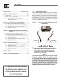
1.1 INTRODUCTION
This battery charger supplies a trickle charging current and voltage
to maintain the charge on the generator starting battery inside the
generator enclosure. The charger will not replenish a fully dis-
charged battery. It is intended to be connected to a 120VAC gen-
erator backed-up circuit only. If it is not connected to a generator
backed-up circuit the battery could go “dead” while the generator
is running for extended periods of time.
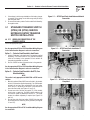
Figure 1.1 — Charger as Supplied Indicating Input and
Output Wiring
DC OutputAC Input
This battery charger must be properly installed
and wired for correct operation of all 2008
model line Air-cooled Standby Generators.
Failure to do so will result in a dead battery
condition at the generator.
NOTE:
This installation guide should be used in conjunction with the
“Installation and Owner’s Manual” that is furnished with the
Air-cooled Standby Generator and the Installation and appropri-
ate transfer switch manual. Please review all manuals prior
to installation of the generator and transfer switch. This bat-
tery charger is not required with the Liquid-cooled Generator
product line. This battery charger is not required for Air-cooled
Standby Generators prior to the 2008 model line. This unit is not
compatible with other generator manufacturer’s products.
Table of Contents
For authorized service, reference
the dealer locator number found
in the generator owner’s manual
or on the generator.

1
These Installation Guidelines are designed to familiarize personnel
with the installation process for the battery charger required for
the air-cooled generator only. It does not replace or supersede any
information contained in any of the written documents shipped
with the unit. This booklet should only be used in conjunction with
the Owner’s Manual, Installation Guide and other technical docu-
ments shipped with the unit.
Future product updates and/or modifications will be reflected in the
written documentation included with the equipment. Always read
all accompanying documentation carefully before attempting to
install any generator, transfer switch or related equipment.
NOTE:
It is essential to comply with all regulations established by the
Occupational Safety and Health Administration (OSHA) and
strict adherence to all local, state and national codes is manda-
tory.
This device should be installed with all local electrical codes
and/or the latest edition of the National Electrical Code. All wir-
ing must be the correct size and type, and must conform to local
codes, standards, and regulations.
1.2 BATTERY CHARGER
COMPATIBILITY
This battery charger is compatible, and required with all 2008
model line Air-cooled Standby Generators. For all generators that
were supplied with a transfer switch/load center, the charger is
already installed in the transfer switch enclosure and this charger
is not needed. For all generators that were NOT supplied with a
transfer switch/load center, the charger is NOT already installed
and MUST be installed according to these guidelines.
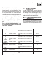
1.2.1 DETERMINATION OF GENERATOR/TRANSFER
SWITCH MODEL TYPE
The Battery charger included with this manual only needs to be
used with certain transfer switch configurations. Some transfer
switch configurations already have the battery charger installed in
the transfer switch. Before proceeding it is necessary to select the
transfer switch used from the following table.
Section 1 — General Information
Battery Charger Installation Guidelines
Switch Type Switch Description Notes Proceed to Section
RTSD Pre-wire with 8 circuit load center
Battery charger is included and pre-wired with the trans-
fer switch. Discard this charger. No further installation is
required
Stop Here
RTSF
ST100R10C
Pre-wire with 10 circuit load
center
Battery charger is included and pre-wired with the trans-
fer switch. Discard this charger. No further installation is
required
Stop Here
RTSH
Pre-wire with 12 circuit load
center
Battery charger is included and pre-wired with the trans-
fer switch. Discard this charger. No further installation is
required
Stop Here
RTSP
ST100R14C
Pre-wire with 14 circuit load
center
Battery charger is included and pre-wired with the trans-
fer switch. Discard this charger. No further installation is
required
Stop Here
RTSW
ST100R16C
KGATX0216100
Pre-wire with 16 circuit load
center
Battery charger is included and pre-wired with the trans-
fer switch. Discard this charger. No further installation is
required
Stop Here
RTSS
KGALT0101200
SR200RDPM
Power Manager LTS - Load Shed
with 16 circuit load center
Battery charger is included with the transfer switch. Proceed
with connections.
2
RTSN
SRXXXR
KGATX
Standard
The included battery charger must be installed and con-
nected
3
RTSE
SRXXXRD
KGATD
Service Entrance Rated
The included battery charger must be installed and con-
nected
3
005448-0
005449-0
KGATD0101RSP
GenReady
The included battery charger must be installed and con-
nected
4
NOTE: Switch Type is the first four (4) digits of the model number and can be found on the data label inside the switch.

2
2.1 LOAD SHED TRANSFER SWITCH
(RTSS) INSTALLATION
2.1.1 WIRING AND CONNECTIONS AT THE
TRANSFER SWITCH
Connect the 15B, 0, and 23 low voltage control wires to the load
shed controller connector J5 per the wiring diagram. Wires should
be sized according to the following table.
CHARGER DC OUTPUT (TRANSFER SWITCH TO GENERATOR)
WIRE SIZE CHART
Maximum Wire Run Length
Recommended Wire Size
(stranded copper)
35 feet (10.67m) No. 16 AWG.
60 feet (18.29m) No. 14 AWG.
90 feet (27.43m) No. 12 AWG.
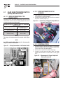
NOTE:
The charger is already mounted in the transfer switch (Figure
2.1).
NOTE:
See RTSS Installation/Wiring Diagram in the "Interconnection
Diagrams" section for connections.
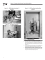
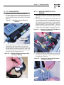
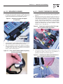
Figure 2.1 — Wiring Connections at the Transfer Switch
Connections
Charger
2.1.2 WIRING AND CONNECTIONS AT THE
GENERATOR
1. Crimp spade lugs onto all three low voltage wires, 15B, 0, and
23 (Purchased or supplied separately).
2. Connect the low voltage wires, 15B, 0, and 23 to the terminal
strip on the controller (Figure 2.2).
Figure 2.2 — Connection of Charger DC Output Wires in
Generator Control Panel
2.1.3 OPERATIONAL TESTING
1. If already connected, disconnect the battery in the generator.
Remove the negative cable first followed by the positive cable.
Take care not to short the cables together.
2. Ensure power is applied to the battery charger input.
3. Connect a volt meter across the battery leads. The voltage
reading should be between 12.8 VDC and 13.8 VDC (Figure
2.3).
Figure 2.3 — Measurement of Charger Output with
Battery Disconnected
Section 2 — Load Shed Transfer Switch Installation
Battery Charger Installation Guidelines

3
4. If the voltage is within range installation of the battery charger
is complete. If the voltage is not within range verify all wiring
and sizing and retest.
5. Re-connect the battery cables. Positive cable first followed by
the negative cable.
3.1 STANDARD TRANSFER SWITCH
(RTSN) OR (RTSE) SERVICE
ENTRANCE RATED TRANSFER
SWITCH INSTALLATION
3.1.1 WIRING AND CONNECTIONS AT THE
TRANSFER SWITCH
Choose the appropriate option.
NOTE:
See the appropriate RTSN or RTSE Installation/Wiring Diagram
in the "Interconnection Diagrams" section for connections.
Option 1 — Protected Load Provided in Load Center
1. Install a 15A breaker in the load center (Purchased or supplied
separately). The breaker must be on a generator backed-up
circuit or the battery in the generator will not maintain its
charge during extended run periods.
2. Run the 120VAC hot wire and neutral wires to the generator.
NOTE:
See the appropriate RTSN or RTSE Installation/Wiring Diagram
in the "Interconnection Diagrams" section for connections.
Option 2 — Protected Load Provided in the RTS, Fuse
Block Installation
NOTE:
This section is only appropriate for 2008 RTSN or RTSE transfer
switches.
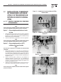
1. Mount the optional 5amp 600V fuse and holder in the transfer
switch. (Purchased or supplied separately). Pre-2008 transfer
switches will not have holes pre-drilled for the fuse holder.
In this case, it is necessary to drill holes in the enclosure to
mount the fuse holder (see Figures 3.1 and 3.4).
2. Connect one side of the fuse to terminal (T1) of the transfer
switch using a spade lug. Pre-2008 transfer switches will
not have the spade lug attached to terminal T1. The spade
terminal is available separately if required (see Figures 3.2
and 3.4).
3. Run the other side of the fuse holder (120VAC Hot) along with
the neutral from the neutral lug to the generator (see Figures
3.1 and 3.5).
NOTE:
See the appropriate RTSN or RTSE Installation/Wiring Diagram
for connections.
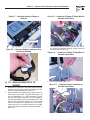
Figure 3.1 — RTSN Fuse Block Installation and Neutral
Connection
Figure 3.2 — RTSN Fuse Block Installation T1
Connection
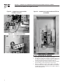
Figure 3.3 — RTSN Fuse Block Installation When
Completed
Section 3 — Standard or Service Entrance Transfer Switch Installation
Battery Charger Installation Guidelines

4
Section 3 — Standard or Service Entrance Transfer Switch Installation
Battery Charger Installation Guidelines
Figure 3.4 — RTSE Fuse Block Installation T1
Connection
Figure 3.5 — RTSE Neutral Connection
Figure 3.6 — RTSE Fuse Block Installation When
Completed
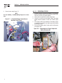
3.1.2 CHARGER MOUNTING
1. Remove the cover over the controller in the generator
2. The battery charger can be located anywhere within the con-
trols area on the generator. It is convenient to mount the char-
ger on the vertical surface on right-hand side of the controller
(Figure 3.7).
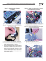
3. Clean the surface where the charger is to be mounted prior to
mounting with a damp cloth and wait for the area to dry.
4. Remove the adhesive covering on the backside of the char-
ger and firmly press the charger into place as shown. Once
mounted the charger may be removed for inspection by sepa-
rating the hook & loop mounting (Figure 3.8).

5
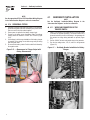
Figure 3.7 — Mounting Location of Charger in
Generator
Charger Mounting
Figure 3.8 — Removal of Adhesive Covering on Hook
and Loop for Mounting
3.1.3 WIRING AND CONNECTIONS AT THE
GENERATOR
1. Identify the DC output wires on the battery charger and crimp
spade lugs onto both the positive and negative lead (pur-
chased or supplied separately) (see Figure 1.1).
2. Attach the positive and negative battery charger leads to the
terminal strip in the controller. The positive lead is either a red
wire or is marked with a (+) or (15B) designation. The nega-
tive lead is black and/or marked with a (-) or (0) designation.
The positive lead attaches to the terminal labeled “15B”. Note
that there will be two wires attached to the “15B” terminal
when the full installation is completed. One for the battery
charger and one for the common connection to the transfer
switch. The negative lead attaches to the terminal labeled “0”
(Figure 3.9).
Figure 3.9 — Connection of Charger DC Output Wires in
Generator Control Panel
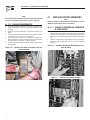
3. Using wire nuts attach the 120VAC input wires from the bat-
tery charger to the generator backed-up 120VAC circuit from
the transfer switch (Figure 3.10).
Figure 3.10 — Connection of Charger AC Input Wires in
Generator Control Panel
4. Dress all wires neatly (Figure 3.11).
Figure 3.11 — Completed Charger Connections on
Generator Control Panel
Section 3 — Standard or Service Entrance Transfer Switch Installation
Battery Charger Installation Guidelines

6
NOTE:
See the appropriate RTSN or RTSE Installation/Wiring Diagram
in the "Interconnection Diagrams" section for connections.
3.1.4 OPERATIONAL TESTING
1. If already connected, disconnect the battery in the generator.
Remove the negative cable first followed by the positive cable.
Take care not to short the cables together.
2. Ensure power is applied to the battery charger input.
3. Connect a volt meter across the battery leads. The voltage
reading should be between 12.8VDC and 13.8VDC (Figure
3.12).
4. If the voltage is within range installation of the battery charger
is complete. If the voltage is not within range verify all wiring
and sizing and retest.
5. Re-connect the battery cables. Positive cable first followed by
the negative cable.
Figure 3.12 — Measurement of Charger Output with
Battery Disconnected
4.1 GENREADY INSTALLATION
NOTE:
See the GenReady Installation/Wiring Diagram in the
"Interconnection Diagrams" section for connections.
4.1.1 WIRING AND CONNECTIONS AT THE
TRANSFER SWITCH
1. Install a 15A breaker in the bottom portion of the load center
(Purchased or supplied separately). The breaker must be on a
generator backed-up circuit or the battery in the generator will
not maintain its charge during extended run periods (Figure
4.1).
2. Run the 120VAC hot wire and neutral wires to the generator.
3. Run the low voltage wires, 15B, 0, and 23 to the generator
(Figure 4.2)
Figure 4.1 — GenReady Breaker Installation for Battery
Charger
Figure 4.2 — GenReady Charger Connections
Section 4 — GenReady Installation
Battery Charger Installation Guidelines

7
4.1.2 CHARGER MOUNTING
1. Remove the cover over the controller in the generator
2. The battery charger can be located anywhere within the con-
trols area on the generator. It is convenient to mount the char-
ger on the vertical surface on right-hand side of the controller
(Figure 4.3).
Figure 4.3 — Mounting Location of Charger in
Generator
Charger Mounting
3. Clean the surface where the charger is to be mounted prior to
mounting with a damp cloth and wait for the area to dry.
4. Remove the adhesive covering on the backside of the char-
ger and firmly press the charger into place as shown. Once
mounted the charger may be removed for inspection by sepa-
rating the hook & loop mounting (Figure 4.4).
Figure 4.4 — Removal of Adhesive Covering on Hook
and Loop for Mounting
4.1.3 WIRING AND CONNECTIONS AT THE
GENERATOR
1. Identify the DC output wires on the battery charger and crimp
spade lugs onto both the positive and negative lead (see
Figure 1.1).
2. Attach the positive and negative battery charger leads to the
terminal strip in the controller. The positive lead is either a red
wire or is marked with a (+) or (15B) designation. The nega-
tive lead is black and/or marked with a (-) or (0) designation.
The positive lead attaches to the terminal labeled “15B”. The
negative lead attaches to the terminal labeled “0”. Note that
there will be two wires attached to both the “0” and the “15B”
terminals when the full installation is completed (Figure 4.5).
Figure 4.5 — Connection of Charger DC Output Wires in
Generator Control Panel
3. Using wire nuts attach the 120VAC input wires from the bat-
tery charger to the generator backed-up 120VAC circuit from
the transfer switch (Figure 4.6).
Figure 4.6 — Connection of charger AC input wires in
generator control panel
Section 4 — GenReady Installation
Battery Charger Installation Guidelines

8
4. Dress all wires neatly (Figure 4.7).
NOTE:
See the GenReady Installation/Wiring Diagram for connec-
tions.
Figure 4.7 — Completed Charger Connections on
Generator Control Panel
4.1.4 OPERATIONAL TESTING
1. If already connected, disconnect the battery in the generator.
Remove the negative cable first followed by the positive cable.
Take care not to short the cables together.
2. Ensure power is applied to the battery charger input.
3. Connect a volt meter across the battery leads. The voltage
reading should be between 12.8VDC and 13.8VDC (Figure
4.8.
4. If the voltage is within range installation of the battery charger
is complete. If the voltage is not within range verify all wiring
and sizing and retest.
5. Re-connect the battery cables. Positive cable first followed by
the negative cable.
Figure 4.8 — Measurement of Charger Output with
Battery Disconnected
Section 4 — GenReady Installation
Battery Charger Installation Guidelines

9
Section 5 — Notes
Battery Charger Installation Guidelines

10
Section 5 — Notes
Battery Charger Installation Guidelines

11
Section 5 — Notes
Battery Charger Installation Guidelines

12
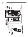
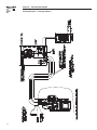
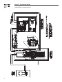
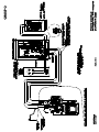
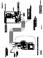
Section 6 — Interconnection Diagrams
Battery Charger Installation Guidelines
RTSS Diagram - Drawing No. 0G8774-C

13
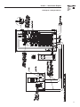
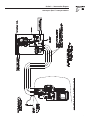
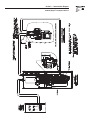
Section 6 — Interconnection Diagrams
Battery Charger Installation Guidelines
RTSS Diagram - Drawing No. 0G8774-C

14
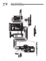
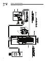
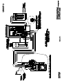
Section 6 — Interconnection Diagrams
Battery Charger Installation Guidelines
RTSN Diagram: Option 1 - Drawing No. 0G8832-A

15
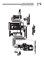
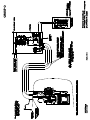
Section 6 — Interconnection Diagrams
Battery Charger Installation Guidelines
RTSN Diagram: Option 2 - Drawing No. 0G8832-A

16
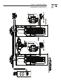
Section 6 — Interconnection Diagrams
Battery Charger Installation Guidelines
RTSE Diagram: Option 1 - Drawing No. 0G8829-A

17
Section 6 — Interconnection Diagrams
Battery Charger Installation Guidelines
RTSE Diagram: Option 2 - Drawing No. 0G8829-A

18
Section 6 — Interconnection Diagrams
Battery Charger Installation Guidelines
GenReady Diagram - Drawing No. 0G4744-F

19
Section 6 — Interconnection Diagrams
Battery Charger Installation Guidelines
GenReady Diagram - Drawing No. 0G4744-F

20
Section 6 — Interconnection Diagrams
Battery Charger Installation Guidelines
GenReady Diagram - Drawing No. 0G4744-F

21
Section 6 — Interconnection Diagrams
Battery Charger Installation Guidelines
GenReady Diagram - Drawing No. 0G4744-F

Part No. 0G7956 Revision D (11/05/09) Printed in U.S.A.

Generador enfriado con aire
Cargador de la batería
Instrucciones de instalación

Índice ........................................Interior de la portada
Sección 1 — Información general ........................ IFC
1.1 Introducción ..................................................................IFC
1.2 Compatibilidad del cargador de la batería ..................... 1
1.2.1 Determinación del tipo de modelo del
conmutador de transferencia o generador .......... 1
Sección 2 — Instalación del conmutador de
transferencia del relé de liberación ... 2
2.1 Instalación del conmutador de transferencia
(RTSS) del relé de liberación .......................................... 2
2.1.1 Cableado y conexiones del
conmutador de transferencia ................................ 2
2.1.2 Cableado y conexiones del generador .............. 2
2.1.3 Prueba de funcionamiento .................................... 2
Section 3 — Sección 3 – Instalación del
conmutador de transferencia para
entrada de servicio o estándar ............ 3
3.1 Instalación del conmutador de transferencia
nominal de entrada de servicio (RTSE) o del
conmutador de transferencia estándar (RTSN).............. 3
3.1.1 Cableado y conexiones del
conmutador de transferencia ................................ 3
3.1.2 Instalación del cargador ...................................... 4
3.1.3 Cableado y conexiones del generador ............... 5
3.1.4 Prueba de funcionamiento ................................... 6
Sección 4 — Instalación de GenReady .................... 6
4.1.1 Cableado y conexiones del
conmutador de transferencia ................................ 6
4.1.2 Instalación del cargador ...................................... 7
4.1.3 Cableado y conexiones del generador ............... 7
4.1.4 Prueba de funcionamiento ................................... 8
Sección 5 – Notas ...................................................... 9
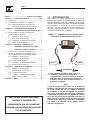
1.1 INTRODUCCIÓN
Este cargador de la batería suministra voltaje y corriente de
carga lenta para mantener la carga de la batería de arranque del
generador dentro de su propia caja. El cargador no puede recargar
una batería completamente descargada. Está diseñado únicamente
para conectarse a un circuito de 120 V CA con respaldo de
generador. Si no está conectado a un circuito accionado por el
generador, la batería podría "agotarse" mientras el generador está
funcionando durante períodos prolongados.
Figura 1.1 — Cargador tal como se entrega, con las
indicaciones de cableado de entrada y salida
DC OutputAC Input
ADVERTENCIA
Este cargador de baterías debe estar bien
instalado y cableado para asegurar el
funcionamiento correcto de todos los modelos
2008 de la línea de generadores de reserva
enfriados con aire. Si no lo está, la batería del
generador se agotará.
NOTA:
La guía de instalación debe utilizarse con el "Manual del
propietario y de instalación" que se entrega con el generador
de reserva enfriado con aire y el manual de instalación
del conmutador de transferencia adecuado. Se recomienda
revisar todos los manuales antes de instalar el generador y
el conmutador de transferencia. Este cargador de la batería
no es necesario para la línea de generadores enfríados con
fluidos. Tampoco es necesario para los generadores de reserva
enfriados con aire anteriores a la línea de los modelos 2008.
Esta unidad no es compatible con los productos de otros
fabricantes de generadores.
Índice
Para obtener servicio autorizado,
remítase al localizador de
concesionarios que se encuentraen
el manual del propietario del generador
o en el generador.

1
Estas instrucciones de instalación tienen por objeto familiarizar al personal
con el proceso de instalación del cargador de baterías necesario para los
generadores enfriados con aire únicamente. No reemplazan ni anulan ningún
tipo de información contenida en ninguno de los documentos escritos
entregados con el equipo. Este folleto sólo debe usarse junto con el Manual
del propietario, la Guía de instalación y otros documentos técnicos entregados
con la unidad.
Toda actualización o modificación de producto futura será incluida en
la documentación escrita que se entrega con el equipo. Lea siempre
y detenidamente todos los documentos que se entregan con cualquier
generador, conmutador de transferencia o equipo relacionado antes de intentar
instalarlo.
NOTA:
Es esencial cumplir con todas las normativas establecidas por la
Administración de Seguridad y Salud Ocupacional (Occupational Safety
and Health Administration, OSHA) y es obligatorio acatar estrictamente
todos los códigos locales, estatales y nacionales.
Este dispositivo debe instalarse de acuerdo con los códigos eléctricos
locales y la última edición del Código Eléctrico Nacional (National Electrical
Code, NEC). Todo el cableado debe ser del tamaño y el tipo correctos, y
cumplir con los códigos, normas y reglamentaciones locales.
1.2 COMPATIBILIDAD DEL
CARGADOR DE LA BATERÍA
El cargador de la batería es compatible, y de uso obligatorio, con la línea
completa de modelos 2008 de los generadores de reserva enfriados con aire.
Todos los generadores entregados con un centro de carga/conmutador de
transferencia, tienen el cargador ya instalado en la caja de dicho conmutador,
por lo que este cargador no es necesario. Todos los generadores que NO
fueron entregados con un centro de carga/conmutador de transferencia, NO
tienen el cargador ya instalado en la caja de dicho conmutador, por lo que este
cargador DEBE instalarse de acuerdo con estas instrucciones.
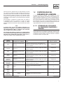
1.2.1 DETERMINACIÓN DEL TIPO DE MODELO
DEL CONMUTADOR DE TRANSFERENCIA O
GENERADOR
El cargador de la batería incluido con este manual sólo es necesario con
ciertas configuraciones del conmutador de transferencia. Algunas de estas
configuraciones ya tienen el cargador de la batería instalado en el conmutador
de transferencia. Antes de proseguir, es necesario seleccionar el conmutador
de transferencia utilizado en la siguiente tabla.
Sección 1 — Información general
Instrucciones de instalación del cargador de la batería
Tipo de
conmutador
Descripción del conmutador Notas Pase a la sección
RTSD
Precableado con el centro de carga
del circuito 8
El cargador de la batería se incluye y está precableado con el
conmutador de transferencia. Deseche el cargador. No se necesita
ninguna otra instalación
Deténgase aquí
RTSF
ST100R10C
Precableado con el centro de carga
del circuito 10
El cargador de la batería se incluye y está precableado con el
conmutador de transferencia. Deseche el cargador. No se necesita
ninguna otra instalación
Deténgase aquí
RTSH
Precableado con el centro de carga
del circuito 12
El cargador de la batería se incluye y está precableado con el
conmutador de transferencia. Deseche el cargador. No se necesita
ninguna otra instalación
Deténgase aquí
RTSP
ST100R14C
Precableado con el centro de carga
del circuito 14
El cargador de la batería se incluye y está precableado con el
conmutador de transferencia. Deseche el cargador. No se necesita
ninguna otra instalación
Deténgase aquí
RTSW
ST100R16C
KGATX0216100
Precableado con el centro de carga
del circuito 16
El cargador de la batería se incluye y está precableado con el
conmutador de transferencia. Deseche el cargador. No se necesita
ninguna otra instalación
Deténgase aquí
RTSS
KGALT0101200
SR200RDPM
Power Manager LTS - Relé de
liberación con el centro de carga del
circuito 16
El cargador de la batería se incluye con el conmutador de
transferencia. Prosiga con las conexiones.
2
RTSN
SRXXXR
KGATX
Estándar
El cargador de la batería incluido debe instalarse
y conectarse
3
RTSE
SRXXXRD
KGATD
Clasificado para entrada
de servicio
El cargador de la batería incluido debe instalarse
y conectarse
3
005448-0
005449-0
KGATD0101RSP
GenReady
El cargador de la batería incluido debe instalarse
y conectarse
4
NOTE: El tipo de conmutador está indicado por los primeros cuatro (4) dígitos del número de modelo que aparece en la etiqueta de información del conmutador.

2
2.1 INSTALACIÓN DEL
CONMUTADOR DE
TRANSFERENCIA DEL RELÉ DE
LIBERACIÓN (RTSS)
2.1.1 CABLEADO Y CONEXIONES DEL CONMUTADOR
DE TRANSFERENCIA
Conecte los cables de control de bajo voltaje 15B, 0 y 23 al conector J5
del controlador del relé de liberación, según lo indicado en el diagrama de
cableado. Los cables deben tener el tamaño descrito en la tabla siguiente.
DIAGRAMA DE TAMAÑOS DE LOS CABLES DE SALIDA CC
DEL CARGADOR (CONMUTADOR DE TRANSFERENCIA AL
GENERADOR)
Longitud máxima de la
extensión del cable
Tamaño de cable
recomendado (trenzado de
cobre)
35 pies (10.67 m) Núm. 16 AWG.
60 pies (18.29 m) Núm. 14 AWG.
90 pies (27.43 m) Núm. 12 AWG.
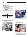
NOTA:
El cargador ya está instalado en el conmutador de transferencia (figura
2.1).
NOTA:
Consulte el diagrama de cableado/instalación de RTSS en la sección
"Diagramas de interconexión" para ver las conexiones.
Figura 2.1 — Conexiones del cableado en el
conmutador de transferencia.
Conexiones
Cargador
2.1.2 CABLEADO Y CONEXIONES DEL GENERADOR
1. Pliegue las orejetas de pala sobre los tres cables de bajo voltaje, 15B, 0
y 23 (se compran o suministran por separado).
2. Conecte los cables de bajo voltaje, 15B, 0 y 23, a la tira del terminal en
el controlador (figura 2.2).
Figura 2.2 — Conexión de los cables de salida CC del carga-
dor en el panel de control del generador
2.1.3 PRUEBA DE FUNCIONAMIENTO
1. Si ya está conectada, desconecte la batería en el generador. Quite
primero el cable negativo y luego el positivo. Tenga cuidado de no juntar
los cables.
2. Asegúrese de que haya alimentación en la entrada del cargador de la
batería.
3. Conecte un voltímetro entre las dos derivaciones de la batería. La lectura
de voltaje debe ser de 12.8 a 13.8 V CC (figura 2.3)
Figura 2.3 — Medición de la salida del cargador con la
batería desconectada
4. Si el voltaje está entre esos límites, la instalación del cargador de la
batería ha finalizado. Si el voltaje no está entre estos límites, verifique el
cableado completo y los tamaños, y pruebe nuevamente.
5. Conecte nuevamente los cables de la batería. Primero el cable positivo y
luego el negativo.
Sección 2 – Instalación del conmutador de transferencia del relé de liberación
Instrucciones de instalación del cargador de la batería

3
3.1
INSTALACIÓN DEL CONMUTADOR
DE TRANSFERENCIA ESTÁNDAR
(RTSN) O DE TRANSFERENCIA DE
ENTRADA DE SERVICIO NOMINAL
(RTSE)
3.1.1 CABLEADO Y CONEXIONES DEL CONMUTADOR
DE TRANSFERENCIA
Elija la opción apropiada.
NOTA:
Consulte el diagrama de cableado/instalación de RTSN o RTSE apropiado
en la sección "Diagramas de interconexión" para ver las conexiones.
Opción 1 — Carga protegida suministrada en el centro
de carga
1. Instale un disyuntor 15A en el centro de carga (se compran o suministran
por separado). El disyuntor debe estar en un circuito respaldado por el
generador, si no lo está, la batería del generador no mantendrá su carga
durante períodos largos de funcionamiento.
2. Conecte los cables neutros y el cable activo de 120 V CA al generador.
NOTA:
Consulte el diagrama de cableado/instalación de RTSN o RTSE apropiado
en la sección "Diagramas de interconexión" para ver las conexiones.
Opción 2 — Carga protegida provista en el RTS,
instalación de la caja de fusibles
NOTA:
Esta sección sólo corresponde a los conmutadores de transferencia RTSN
o RTSE 2008.
1. Instale el fusible opcional de 5 A y 600 V junto con el portafusible en el
conmutador de transferencia. (Se compran o suministran por separado).
Los conmutadores de transferencia anteriores a los modelos 2008 no
vienen con los orificios perforados para el portafusible. En ese caso, es
necesario perforar orificios en la caja para montar el portafusible (vea
las figuras 3.1 y 3.4).
2. Conecte un lado del fusible al terminal (T1) del conmutador de
transferencia utilizando una orejeta de pala. Los conmutadores de
transferencia anteriores al 2008 no tendrán la orejeta de pala adosada
al terminal T1. El terminal de pala puede adquirirse por separado, si es
necesario (vea las figuras 3.2 y 3.4).
3. Coloque el otro lado del portafusible (activo de 120 V CA) junto con el
neutro desde la orejeta neutra al generador (vea las figuras 3.1 y 3.5).
NOTA:
Consulte el diagrama de cableado/instalación de RTSN o RTSE apropiado
para ver las conexiones.
Figura 3.1 — Instalación de la caja de fusibles del RTSN y
conexión neutra
Figura 3.2 — Instalación de la caja de fusibles del RTSN y
conexión T1
Figura 3.3 — Instalación de la caja de fusibles
del RTSN una vez finalizada
Sección 3 – Instalación del conmutador de transferencia para entrada de servicio o estándar
Instrucciones de instalación del cargador de la batería

4
Sección 3 – Instalación del conmutador de transferencia para entrada de servicio o estándar
Instrucciones de instalación del cargador de la batería
Figura 3.4 — Instalación de la caja de fusibles
del RTSE y conexión T1
Figura 3.5 — Conexión neutra del RTSE
Figure 3.6 — Instalación de la caja de fusibles del RTSE una
vez finalizada
3.1.2 INSTALACIÓN DEL CARGADOR
1. Quite la tapa colocada sobre el controlador en el generador
2. El cargador de la batería puede encontrarse en cualquier lugar del área
de controles del generador. Es conveniente montar el cargador en la
superficie vertical del lado derecho del controlador (figura 3.7).
3. Con un paño húmedo, limpie la superficie donde va a colocar el cargador
antes de instalarlo, y espere un día para que el área se seque.
4. Quite la tira adhesiva que cubre la parte posterior del cargador y
presiónelo firmemente en su lugar, como se muestra. Una vez colocado,
el cargador puede retirarse para revisarlo con solo separar el gancho y
retén de montaje (figura 3.8).

5
Figura 3.7 — Ubicación del montaje del cargador
en el generador
Montaje del cargador
Figura 3.8 — Cómo quitar la cubierta adhesiva del gancho y
del retén para el montaje
3.1.3 CABLEADO Y CONEXIONES DEL GENERADOR
1. Identifique los cables de salida CC en el cargador de la batería y pliegue
las orejetas de pala en ambas derivaciones, positiva y negativa (se
compran o suministran por separado) (vea la figura 1.1).
2. Acople las derivaciones positiva y negativa del cargador de la batería a la
tira del terminal en el controlador. La derivación positiva es un cable rojo
o está marcada con una indicación (+) o (15B). La derivación negativa
es negra o está marcada con una indicación (-) o (0). La derivación
positiva se conecta al terminal rotulado "15B". Observe que cuando
la instalación completa esté terminada habrá dos cables acoplados al
terminal "15B". Uno para el cargador de la batería y otro para la coneción
común al conmutador de transferencia. La derivación negativa se acopla
al terminal rotulado "0" (figura 3.9).
Figura 3.9 — Conexión de los cables de salida CC del carga-
dor en el panel de control del generador
3. Con tuercas para cables, conecte los cables de entrada de 120 V CA
del cargador de la batería al circuito de 120 V CA respaldado por el
generador del conmutador de transferencia (figura 3.10).
Figura 3.10 — Conexión de los cables de entrada CA del cargador
en el panel de control del generador
4. Cubra cuidadosamente todos los cables (figura 3.11).
Figura 3.11 — Conexiones al cargador terminadas
en el panel de control del generador
Sección 3 – Instalación del conmutador de transferencia para entrada de servicio o estándar
Instrucciones de instalación del cargador de la batería

6
NOTA:
Consulte el diagrama de cableado/instalación de RTSN o RTSE apropiado
en la sección "Diagramas de interconexión" para ver las conexiones.
3.1.4 PRUEBA DE FUNCIONAMIENTO
1. Si ya está conectada, desconecte la batería en el generador. Quite
primero el cable negativo y luego el positivo. Tenga cuidado de no juntar
los cables.
2. Asegúrese de que haya alimentación en la entrada del cargador de la
batería.
3. Conecte un voltímetro entre las dos derivaciones de la batería. La lectura
del voltaje debe ser de 12.8 a 13.8 V CC (figura 3.12).
4. Si el voltaje está entre esos límites, la instalación del cargador de la
batería ha finalizado. Si el voltaje no está entre estos límites, verifique el
cableado completo y los tamaños, y pruebe nuevamente.
5. Conecte nuevamente los cables de la batería. Primero el cable positivo y
luego el negativo.
Figura 3.12 — Medición de la salida del cargador con la bat-
ería desconectada
4.1 INSTALACIÓN DE GENREADY
NOTA:
Consulte el diagrama de cableado/instalación de GenReady en la sección
"Diagramas de interconexión" para ver las conexiones.
4.1.1 CABLEADO Y CONEXIONES DEL CONMUTADOR
DE TRANSFERENCIA
1. Instale un disyuntor de 15A en la parte inferior del centro de carga (se
compra o suministra por separado). El disyuntor debe estar en un circuito
respaldado por el generador, si no lo está, la batería del generador no
mantendrá su carga durante períodos largos de funcionamiento (figura
4.1).
2. Conecte los cables neutros y el cable activo de 120 V CA al generador.
3. Extienda los cables de bajo voltaje, 15B, 0 y 23 hasta el generador
(figura 4.2)
Figura 4.1 — Instalación del disyuntor GenReady para el car-
gador de batería
Figura 4.2 — Conexiones del cargador GenReady
Sección 4 — Instalación de GenReady
Instrucciones de instalación del cargador de la batería

7
4.1.2 INSTALACIÓN DEL CARGADOR
1. Quite la tapa colocada sobre el controlador en el generador
2. El cargador de la batería puede encontrarse en cualquier lugar del área
de controles del generador. Es conveniente montar el cargador en la
superficie vertical del lado derecho del controlador (figura 4.3).
Figura 4.3 — Ubicación del montaje del cargador
en el generador
Montaje del cargador
3. Con un paño húmedo, limpie la superficie donde va a colocar el cargador
antes de instalarlo, y espere un día para que el área se seque.
4. Quite la tira adhesiva que cubre la parte posterior del cargador y
presiónelo firmemente en su lugar, como se muestra. Una vez colocado,
el cargador puede quitarse para su inspección con sólo separar el
gancho y el retén de montaje (figura 4.4).
Figura 4.4 — Cómo quitar la cubierta adhesiva del gancho y
del retén para el montaje
4.1.3 CABLEADO Y CONEXIONES DEL GENERADOR
1. Identifique los cables de salida CC en el cargador de la batería y pliegue
las orejetas de pala en las dos derivaciones, positiva y negativa (vea la
figura 1.1).
2. Acople las derivaciones positiva y negativa del cargador de la batería a la
tira del terminal en el controlador. La derivación positiva es un cable rojo
o está marcada con una indicación (+) o (15B). La derivación negativa
es negra o está marcada con una indicación (-) o (0). La derivación
positiva se conecta al terminal rotulado "15B". La derivación negativa
se conecta al terminal rotulado "0". Observe que cuando la instalación
completa esté terminada habrá dos cables conectados a ambos
terminales, el "0" y el "15B" (figura 4.5).
Figura 4.5 — Conexión de los cables de salida CC del carga-
dor en el panel de control del generador
3. Con tuercas para cables, conecte los cables de entrada de 120 V CA
del cargador de la batería al circuito de 120 V CA respaldado por el
generador del conmutador de transferencia (figura 4.6).
Figura 4.6 — Conexión de los cables de entrada CA del car-
gador en el panel de control del generador
Sección 4 — Instalación de GenReady
Instrucciones de instalación del cargador de la batería

8
4. Cubra cuidadosamente todos los cables (figura 4.7).
NOTA:
Consulte el diagrama de cableado/instalación de GenReady para ver las
conexiones.
Figura 4.7 — Conexiones al cargador terminadas en el
panel de control del generador
4.1.4 PRUEBA DE FUNCIONAMIENTO
1. Si ya está conectada, desconecte la batería en el generador. Quite
primero el cable negativo y luego el positivo. Tenga cuidado de no juntar
los cables.
2. Asegúrese de que haya alimentación en la entrada del cargador de la
batería.
3. Conecte un voltímetro entre las dos derivaciones de la batería. La lectura
del voltaje debe ser de 12.8 a 13.8 V CC (figura 4.8).
4. Si el voltaje está entre esos límites, la instalación del cargador de la
batería ha finalizado. Si el voltaje no está entre estos límites, verifique el
cableado completo y los tamaños, y pruebe nuevamente.
5. Conecte nuevamente los cables de la batería. Primero el cable positivo y
luego el negativo.
Figura 4.8 — Medición de la salida del cargador
con la batería desconectada
Sección 4 — Instalación de GenReady
Instrucciones de instalación del cargador de la batería

9
Sección 5 — Notas
Instrucciones de instalación del cargador de la batería

Pieza núm. 0G7956 Revisión D (05/11/09) Impreso en EE.UU.


-
 1
1
-
 2
2
-
 3
3
-
 4
4
-
 5
5
-
 6
6
-
 7
7
-
 8
8
-
 9
9
-
 10
10
-
 11
11
-
 12
12
-
 13
13
-
 14
14
-
 15
15
-
 16
16
-
 17
17
-
 18
18
-
 19
19
-
 20
20
-
 21
21
-
 22
22
-
 23
23
-
 24
24
-
 25
25
-
 26
26
-
 27
27
-
 28
28
-
 29
29
-
 30
30
-
 31
31
-
 32
32
-
 33
33
-
 34
34
-
 35
35
-
 36
36
-
 37
37
-
 38
38
-
 39
39
-
 40
40


