Generac GP5500 005939R5 Manual de usuario
- Categoría
- Generadores de poder
- Tipo
- Manual de usuario

Owner's Manual
GP Series Portable Generator
www.generac.com or 1-888-436-3722
DEADLY EXHAUST FUMES! ONLY use OUTSIDE
far away from windows, doors and vents!
NOT INTENDED FOR USE IN CRITICAL LIFE
SUPPORT APPLICATIONS.
SAVE this Manual. Provide this manual to any
operator of the generator.

Introduction ............................................................. 1
Read this Manual Thoroughly ................................. 1
Safety Rules ........................................................... 1
Standards Index .............................................................3
General Information ................................................ 4
1.1 Unpacking ......................................................................4
1.1.1 Accessories .......................................................4
1.2 Assembly .......................................................................4
1.2.1 Assembling the Accessory Kit............................4
1.2.2 Battery Cable Connection (Electric Start Only) ....4
1.3 Emissions Information ....................................................5
Operation ................................................................ 5
2.1 Know the Generator .......................................................5
2.2 Hourmeter ......................................................................6
2.3 Cord Sets and Connection Plugs ....................................6
2.3.1 120 VAC, 20 Amp, Duplex Receptacle ...............6
2.3.2 120/240 VAC, 30 Amp, Receptacle ....................6
2.4 How to Use the Generator ..............................................7
2.4.1 Grounding the Generator When Used
as a Portable .....................................................7
2.4.2 Connecting to a Building's Electrical System ......7
2.5 Don’t Overload the Generator ..........................................8
2.6 Wattage Reference Guide ...............................................8
2.7 Before Starting the Generator .........................................9
2.7.1 Adding Engine Oil ..............................................9
2.7.2 Adding Gasoline .................................................9
2.8 Starting Pull Start Engines ............................................10
2.9 Starting Electric Start Engines ......................................10
2.10 Stopping the Engine .....................................................11
2.11 Low Oil Level Shutdown System ..................................11
2.11.1 Sensing Low Oil Level ......................................11
2.12 Charging the Battery (Electric Start Units Only) .............11
Maintenance ......................................................... 12
3.1 Performing Scheduled Maintenance .............................12
3.2 Maintenance Schedule .................................................12
3.3 Product Specifications ..................................................12
3.3.1 Generator Specifications ..................................12
3.3.2 Engine Specifications .......................................12
3.3.3 Emissions Information .....................................12
3.3.4 High Altitude Operation ....................................12
3.4 General Recommendations ...........................................12
3.4.1 Generator Maintenance ....................................12
3.4.2 To Clean the Generator .....................................13
3.4.3 Engine Maintenance .........................................13
3.4.4 Checking Oil Level ...........................................13
3.4.5 Changing the Oil ..............................................13
3.4.6 Replacing the Spark Plug .................................13
3.4.7 Battery Replacement (If Applicable) .................13
3.5 Service Air Filter ...........................................................14
3.6 Valve Clearance ............................................................14
3.7 General ........................................................................14
3.8 Long Term Storage .......................................................14
3.9 Other Storage Tips .......................................................14
Troubleshooting .................................................... 15
4.1 Troubleshooting Guide ..................................................15
Table of Contents

INTRODUCTION
Thank you for purchasing this model by Generac Power Systems,
Inc. This model is a compact, high performance, air-cooled,
engine driven generator designed to supply electrical power to
operate electrical loads where no utility power is available or in
place of utility due to a power outage.
READ THIS MANUAL THOROUGHLY
If any portion of this manual is not understood, contact the
nearest Authorized Dealer for starting, operating and servicing
procedures.
The operator is responsible for proper and safe use of the
equipment. We strongly recommend that the operator read this
manual and thoroughly understand all instructions before using the
equipment. We also strongly recommend instructing other users to
properly start and operate the unit. This prepares them if they need
to operate the equipment in an emergency. Save these instructions
for future reference. If you loan this device to someone, ALWAYS
loan these instructions to the individual as well.
The generator can operate safely, efficiently and reliably only if it
is properly located, operated and maintained. Before operating or
servicing the generator:
• Become familiar with and strictly adhere to all local, state and
national codes and regulations.
• Study all safety warnings in this manual and on the product
carefully.
• Become familiar with this manual and the unit before use.
The manufacturer cannot anticipate every possible circumstance
that might involve a hazard. The warnings in this manual, and on
tags and decals affixed to the unit are, therefore, not all inclusive.
If using a procedure, work method or operating technique that the
manufacturer does not specifically recommend, ensure that it is
safe for others. Also make sure the procedure, work method or
operating technique utilized does not render the generator unsafe.
THE INFORMATION CONTAINED HEREIN WAS BASED ON
MACHINES IN PRODUCTION AT THE TIME OF PUBLICATION.
GENERAC RESERVES THE RIGHT TO MODIFY THIS MANUAL AT
ANY TIME.
SAFETY RULES
Throughout this publication, and on tags and decals affixed to the
generator, DANGER, WARNING, CAUTION and NOTE blocks are
used to alert personnel to special instructions about a particular
operation that may be hazardous if performed incorrectly or
carelessly. Observe them carefully. Their definitions are as
follows:
INDICATES A HAZARDOUS SITUATION OR ACTION WHICH, IF
NOT AVOIDED, WILL RESULT IN DEATH OR SERIOUS INJURY.
Indicates a hazardous situation or action which, if not
avoided, could result in death or serious injury.
Indicates a hazardous situation or action which, if not
avoided, could result in minor or moderate injury.
NOTE:
Notes contain additional information important to a procedure
and will be found within the regular text body of this manual.
These safety warnings cannot eliminate the hazards that they
indicate. Common sense and strict compliance with the special
instructions while performing the action or service are essential to
preventing accidents.
Four commonly used safety symbols accompany the DANGER,
WARNING and CAUTION blocks. The type of information each
indicates is as follows:
This symbol points out important safety
information that, if not followed, could
endanger personal safety and/or property of
others.
This symbol points out potential explosion
hazard.
This symbol points out potential fire hazard.
This symbol points out potential electrical
shock hazard.
GENERAL HAZARDS
• NEVER operate in an enclosed area, in a vehicle, or indoors
EVEN IF doors and windows are open.
• For safety reasons, the manufacturer recommends that the
maintenance of this equipment is carried out by an Authorized
Dealer. Inspect the generator regularly, and contact the nearest
Authorized Dealer for parts needing repair or replacement.
• Operate generator only on level surfaces and where it will not be
exposed to excessive moisture, dirt, dust or corrosive vapors.
• Keep hands, feet, clothing, etc., away from drive belts, fans,
and other moving parts. Never remove any fan guard or shield
while the unit is operating.
• Certain parts of the generator get extremely hot during
operation. Keep clear of the generator until it has cooled to
avoid severe burns.
• Do NOT operate generator in the rain.
• Do not alter the construction of the generator or change
controls which might create an unsafe operating condition.
• Never start or stop the unit with electrical loads connected
to receptacles AND with connected devices turned ON. Start
the engine and let it stabilize before connecting electrical
loads. Disconnect all electrical loads before shutting down the
generator.
• Do not insert objects through unit’s cooling slots.
• When working on this equipment, remain alert at all times.
Never work on the equipment when physically or mentally
fatigued.
Introduction
1

• Never use the generator or any of its parts as a step. Stepping
on the unit can stress and break parts, and may result in
dangerous operating conditions from leaking exhaust gases,
fuel leakage, oil leakage, etc.
EXHAUST & LOCATION HAZARDS
• Never operate in an enclosed area or indoors! NEVER use in
the home, in a vehicle, or in partly enclosed areas such as
garages, EVEN IF doors and windows are open! ONLY use
outdoors and far from open windows, doors, vents, and in an
area that will not accumulate deadly exhaust.
• The engine exhaust fumes contain carbon monoxide, which
you cannot see or smell. This poisonous gas, if breathed in
sufficient concentrations, can cause unconsciousness or even
death.
• Adequate, unobstructed flow of cooling and ventilating air
is critical to correct generator operation. Do not alter the
installation or permit even partial blockage of ventilation
provisions, as this can seriously affect safe operation of the
generator. The generator MUST be operated outdoors.
• This exhaust system must be properly maintained. Do nothing
that might render the exhaust system unsafe or in noncompliance
with any local codes and/or standards.
• Always use a battery operated carbon monoxide alarm indoors,
installed according to the manufacturers instructions.
• If you start to feel sick, dizzy, or weak after the generator has
been running, move to fresh air IMMEDIATELY. See a doctor, as
you could have carbon monoxide poisoning.
ELECTRICAL HAZARDS
• The generator produces dangerously high voltage when in
operation. Avoid contact with bare wires, terminals, connections,
etc., while the unit is running, even on equipment connected
to the generator. Ensure all appropriate covers, guards and
barriers are in place before operating the generator.
• Never handle any kind of electrical cord or device while
standing in water, while barefoot or while hands or feet are wet.
DANGEROUS ELECTRICAL SHOCK MAY RESULT.
• The National Electric Code (NEC) requires the frame and external
electrically conductive parts of the generator be properly
connected to an approved earth ground. Local electrical codes
may also require proper grounding of the generator. Consult
with a local electrician for grounding requirements in the area.
• Use a ground fault circuit interrupter in any damp or highly
conductive area (such as metal decking or steel work).
• Do not use worn, bare, frayed or otherwise damaged electrical
cord sets with the generator.
• Before performing any maintenance on the generator, disconnect
the engine starting battery (if equipped) to prevent accidental
start up. Disconnect the cable from the battery post indicated
by a NEGATIVE, NEG or (–) first. Reconnect that cable last.
• In case of accident caused by electric shock, immediately shut
down the source of electrical power. If this is not possible,
attempt to free the victim from the live conductor. AVOID
DIRECT CONTACT WITH THE VICTIM. Use a non-conducting
implement, such as a rope or board, to free the victim from the
live conductor. If the victim is unconscious, apply first aid and
get immediate medical help.
FIRE HAZARDS
• Gasoline is highly FLAMMABLE and its vapors are EXPLOSIVE.
Never permit smoking, open flames, sparks or heat in the
vicinity while handling gasoline.
• Never add fuel while unit is running or hot. Allow engine to cool
completely before adding fuel.
• Never fill fuel tank indoors. Comply with all laws regulating
storage and handling of gasoline.
• Do not overfill the fuel tank. Always allow room for fuel
expansion. If tank is over-filled, fuel can overflow onto a hot
engine and cause FIRE or an EXPLOSION. Never store generator
with fuel in tank where gasoline vapors might reach an open
flame, spark or pilot light (as on a furnace, water heater or
clothes dryer). FIRE or EXPLOSION may result. Allow unit to
cool entirely before storage.
• Wipe up any fuel or oil spills immediately. Ensure that no
combustible materials are left on or near the generator. Keep the
area surrounding the generator clean and free from debris and
keep a clearance of five (5) feet on all side to allow for proper
ventilation of the generator.
Safety Rules
2

• Do not insert objects through unit’s cooling slots.
• Never operate the generator if connected electrical devices
overheat, if electrical output is lost, if engine or generator sparks
or if flames or smoke are observed while unit is running.
• Keep a fire extinguisher near the generator at all times.
STANDARDS INDEX
1. National Fire Protection Association (NFPA) 70: The NATIONAL
ELECTRIC CODE (NEC) available from www.nfpa.org
2. National Fire Protection Association (NFPA) 5000: BUILDING
CONSTRUCTION AND SAFETY CODE available from www.
nfpa.org
3. International Building Code available from www.iccsafe.org
4. Agricultural Wiring Handbook available from www.rerc.org ,
Rural Electricity Resource Council P.O. Box 309 Wilmington,
OH 45177-0309
5. ASAE EP-364.2 Installation and Maintenance of Farm Standby
Electric Power available from www.asabe.org, American
Society of Agricultural & Biological Engineers 2950 Niles
Road, St. Joseph, MI 49085
This list is not all inclusive. Check with the Authority Having Local
Jurisdiction (AHJ) for any local codes or standards which may be
applicable to your jurisdiction.
MODEL NO:
SERIAL NO:
Unit ID Location
MODEL
DATA
DECAL
CALIFORNIA PROPOSITION 65 WARNING
Engine exhaust and some of its constituents are known
to the State of California to cause cancer, birth defects
and other reproductive harm.
CALIFORNIA PROPOSITION 65 WARNING
This product contains or emits chemicals known to the
State of California to cause cancer, birth defects and
other reproductive harm.
Safety Rules
3

4
1.1 UNPACKING
• Remove all packaging material.
• Remove separate accessory box.
• Remove the generator from carton.
1.1.1 ACCESSORIES
Check all contents. If any parts are missing or damaged, locate an
authorized dealer at 1-888-436-3722.
• 1 - Owner’s Manual • 1 - Handle Assembly
• 1 - Liter Oil SAE 30 • 2 - Frame Foot
• 2 - Never-Flat Wheels • 1 - Battery Charger
• 2 - Product Registration Cards (Electric Start only)
• 1 - Service Warranty • 1 - Emissions Warranty
• 1 - Hardware Bag (containing the following):
– 2-Rubber Feet – 6-M8 Bolt (Long)
– 2-1/2” Axle Pins
– 2-M6 Bolts (Long)
– 2-Cotter Pins
– 2-M8 Acorn Nut
– 2-1/2” Flat Washers
– 4-Hex Flanged M8 Nuts
– 2-Hex Flanged M6 Nuts
1.2 ASSEMBLY
The generator requires some assembly prior to using it. If problems
arise when assembling the generator, please call the Generator
Helpline at 1-888-436-3722.
1.2.1 ASSEMBLING THE ACCESSORY KIT
The wheels are designed into the unit to greatly improve the
portability of the generator.
You will need the following tools to properly install the accessory
kit.
• Needle Nose Pliers
• Ratchet and 8mm, 10mm, and 13mm sockets
• 8mm, 10mm, and 13mm box wrenches
NOTE:
The wheels are not intended for over-the-road use.
1. Refer to Figure 1 and install the Wheels as follows:
– Slide the Axle Pin through the Wheel, 1/2" Flat Washer, and Wheel
Bracket on the frame.
– Insert the Cotter Pin through the Axle Pin then bend the tabs (of the
Cotter Pins) outward to lock into place.
2. Refer to Figure 1 and install the Frame Foot and Rubber
Bumpers as shown.
– Slide the Rubber Bumper studs through the Frame Foot then install
the Locking Flange Nuts.
– Slide the Hex Head Bolts through the holes in the Frame Rail.
– Slide the Frame Foot onto the Hex Head Bolts then install the
Locking Flange Nuts.
3. Refer to Figure 1 and install the Handle as shown.
– Slide the long Bolts through the Handle Bracket and Handle, then
install the Hex Nuts.
Figure 1 – Wheel & Handle Assembly
2 X RUBBER FOOT
2 X M6 BOLT
(LONG)
2 X M6 NUTS
4 X M8 NUTS
2 X FRAME FOOT
2 X AXLE PIN
2 X WHEEL
2 X 1/2” FLAT WASHER
2 X COTTER PIN
4 X M8 BOLT
(LONG)
2 X M8 BOLT (LONG)
2 X M8 ACORN NUT
HANDLE
ASSEMBLY
1.2.2 BATTERY CABLE CONNECTION (ELECTRIC START
ONLY)
The unit has been deliberately shipped with the battery cables
disconnected.
To connect the battery, you will need two 8mm box wrenches to
connect the battery cables. (see Figure 15 for connection details):
1. Cut off cable ties securing battery cables and remove red
covers from battery terminals.
2. First, connect the red cable to the positive (+) battery terminal
with the bolt and nut supplied.
3. Make sure connections are secure and slide rubber boot over
the positive (+) battery terminal and connection hardware.
4. Connect the black cable to the negative (-) battery terminal
with the bolt and nut supplied and slide rubber boot over the
negative (-) battery terminal and connection hardware.
5. Make sure all connections are secure.
NOTE:
If the battery is unable to start the engine, charge it with the
12V charger included in the accessory box (see the "Charging a
Battery" section for details).
General Information

5
1.3 EMISSIONS INFORMATION
The Environmental Protection Agency requires that this generator
comply with exhaust and evaporative emission standards. This
generator is certified to operate on gasoline. The emission control
system includes the following components:
• Air Induction System
– Intake Pipe / Manifold
– Air Cleaner
• Fuel System
– Carburetor
– Fuel Tank / Cap
– Fuel Lines
– Evaporative Vent Lines
• Ignition System
– Spark Plug
– Ignition Module
• Exhaust System
– Exhaust Manifold
– Muffler
2.1 KNOW THE GENERATOR
Read the Owner’s Manual and Safety Rules before operating
this generator.
Compare the generator to Figures 2 through 4 to become
familiarized with the locations of various controls and adjustments.
Save this manual for future reference.
1. 120 Volt AC, 20 Amp, Duplex Receptacle – Supplies electrical
power for the operation of 120 Volt AC, 20 Amp, single-phase,
60 Hz electrical lighting, appliance, tool and motor loads.
2. 120/240 Volt AC, 30 Amp Locking Receptacle – Supplies
electrical power for the operation of 120 and/or 240 Volt AC,
30 Amp, single-phase, 60 Hz, electrical lighting, appliance,
tool and motor loads.
3. Circuit Breakers (AC) – Each receptacle is provided with a
push-to-reset circuit breaker to protect the generator against
electrical overload.
4. Oil Drain – Use to drain engine oil.
5. Air Filter – Filters intake air as it is drawn into the engine.
6. Choke Knob – Used when starting a cold engine.
7. Fuel Tank – See generator Specifications for tank capacity.
8. Grounding Lug – Ground the generator to an approved earth
ground here. See "Grounding the Generator" for details.
9. Run/Stop Switch – Controls the operation of the generator
(pull start models).
9A. Start Switch – Used to start engine from the starter motor
(electric start models only).
10. Muffler – Quiets the engine.
11. Handle – Pivot and retract for storage. Press the spring-
loaded button to move handles.
12. Gas Cap – Fuel fill location.
13. Fuel Gauge – Shows fuel level in tank.
14. Oil Fill – Add oil here.
15. Recoil Starter – Use to start engine manually.
16. Fuel Shut Off – Valve between fuel tank and carburetor.
17. Roll Over Valve – Passes fuel to the engine airbox.
18. Recovery Hose – Install between the carbon canister and the
roll over valve.
19. Hourmeter – Tracks hours of operation.
20. Battery Charger Input – This receptacle allows the capability
to recharge the 12 volt DC storage battery provided with
the 12 Volt Adaptor Plug Charger which is included in the
Accessory Box. Located behind the battery charger input is
a 1.50 Amp in-line fuse which is inside the control panel to
protect the battery (electric start models only).
21. Battery – Powers the electric starter (electric start models
only).
Figure 2 - Control Panel
20
9A
19
2
3
1
Figure 3 - Generator Controls
17
18
6
5
11
15
16
Operation

6
Figure 4 - Generator Controls
2.2 HOURMETER
The Hourmeter tracks hours of operation for scheduled maintenance
(Figure 5):
There will be a "CHG OIL" message every 100 hours. The message
will flash one hour before and one hour after each 100 hour
interval, providing a two hour window to perform service.
This message will actually begin flashing at 99 hours and disable
itself at 101 hours again, providing a two hour window to perform
the service.
Every 200 hours the "SVC" icon on the lower left hand corner of
the display will flash. The message will flash one hour before and
one hour after each 200 hour interval providing a two hour window
to perform service.
When the hour meter is in the Flash Alert mode, the maintenance
message will always alternate with elapsed time in hours and
tenths. The hours will flash four times, then alternate with the
maintenance message four times until the meter resets itself.
• 100 hours - CHG OIL — Oil Change Interval (Every 100 hrs)
• 200 hours - SVC — Service Air Filter (Every 200 hrs)
Note:
The hour glass graphic will flash on and off when the engine
is running. This signifies that the meter is tracking hours of
operation.
Figure 5 – Hourmeter
HOUR GLASS
GRAPHIC
RESET BUTTON
(IF EQUIPPED)
0000.0
2.3 CORD SETS AND CONNECTION PLUGS
2.3.1 120 VAC, 20 AMP, DUPLEX RECEPTACLE
This is a 120 Volt outlet protected against overload by a 20 Amp
push-to-reset circuit breaker (Figure 6). Use each socket to power
120 Volt AC, single phase, 60 Hz electrical loads requiring up to a
combined 2400 watts (2.4 kW) or 20 Amps of current. Use only
high quality, well-insulated, 3-wire grounded cord sets rated for
125 Volts at 20 Amps (or greater).
Keep extension cords as short as possible, preferably less than
15 feet long, to prevent voltage drop and possible overheating of
wires.
Figure 6 - 120 Volt AC, 20 Amp, Duplex Receptacle
2.3.2 120/240 VAC, 30 AMP RECEPTACLE
Use a NEMA L14-30 plug with this receptacle (rotate to lock/
unlock). Connect a suitable 4-wire grounded cord set to the plug
and to the desired load. The cord set should be rated for 250 Volts
AC at 30 Amps (or greater) (Figure 7).
Use this receptacle to operate 120 Volt AC, 60 Hz, single phase
loads requiring up to 3600 watts (3.6 kW) of power at 30 Amps
or 240 Volt AC, 60 Hz, single phase loads requiring up to 7200
watts (7.2 kW) of power at 30 Amps. The outlet is protected by
two 25 Amp (5.5kW) or two 30 Amp (7.5kW) push-to-reset circuit
breakers.
Operation

7
Figure 7 - 120/240 VAC, 30 Amp Receptacle
2.4 HOW TO USE THE GENERATOR
See the "To Start the Engine" section for how to safely start and
stop the generator and how to connect and disconnect loads. If
there are any problems operating the generator, please call the
generator helpline at 1-888-436-3722.
Never operate in an enclosed area or indoors!
NEVER use in the home, in a vehicle, or in
partly enclosed areas such as garages, EVEN
IF doors and windows are open! ONLY use
outdoors and far from open windows, doors,
vents, and in an area that will not accumulate
deadly exhaust.
The engine exhaust fumes contain carbon
monoxide, which you cannot see or smell.
This poisonous gas, if breathed in sufficient
concentrations, can cause unconsciousness or
even death.
Adequate, unobstructed flow of cooling and
ventilating air is critical to correct generator
operation. Do not alter the installation or permit
even partial blockage of ventilation provisions,
as this can seriously affect safe operation
of the generator. The generator MUST be
operated outdoors.
This exhaust system must be properly
maintained. Do nothing that might render the
exhaust system unsafe or in noncompliance
with any local codes and/or standards.
Always use a battery operated carbon
monoxide alarm indoors, installed according to
the manufacturer's instructions.
2.4.1 GROUNDING THE GENERATOR WHEN USED AS A
PORTABLE
This generator has an equipment ground that connects the
generator frame components to the ground terminals on the AC
output receptacles (see NEC 250.34 (A) for explanation). This
allows the generator to be used as a portable without grounding
the frame of the generator as specified in NEC 250.34.
Special Requirements
There may be Federal or State Occupational Safety and Health
Administration (OSHA) regulations, local codes, or ordinances that
apply to the intended use of the generator.
Please consult a qualified electrician, electrical inspector, or the
local agency having jurisdiction:
• In some areas, generators are required to be registered with
local utility companies.
• If the generator is used at a construction site, there may be
additional regulations which must be observed.
2.4.2 CONNECTING THE GENERATOR TO A BUILDING’S
ELECTRICAL SYSTEM
Connections for standby power to a building’s electrical system
must be made by a qualified electrician and in strict compliance
with all national and local electrical codes and laws. The
connection must isolate the generator power from utility power or
other alternative power sources.
NOTE:
Because the generator equipment ground is bonded to the AC
neutral wires in the generator, either a 3-pole transfer switch or
a 2 pole transfer switch with a switching neutral kit is required
to connect this generator to a building load. In this application
the generator becomes a separately derived system (see NEC
250.20 (D)), and must be grounded in accordance with the
national or local electrical code requirements.
Operation

8
Grounding the Generator in a Building Standby Application
The National Electrical Code requires that the
frame and external electrically conductive parts
of this generator be properly connected to an
approved earth ground.
Local electrical codes may also require proper grounding of
the unit (Figure 8). For that purpose, connecting a No. 10 AWG
(American Wire Gauge) stranded copper wire to the grounding lug
and to an earth-driven copper or brass grounding rod (electrode)
provides adequate protection against electrical shock. However,
local codes may vary widely. Consult with a local electrician for
grounding requirements in the area.
Proper grounding of the generator will help prevent electrical
shock in the event of a ground fault condition in the generator or in
connected electrical devices. Proper grounding also helps dissipate
static electricity, which often builds up in ungrounded devices.
Figure 8 - Grounding the Generator
2.5 DON’T OVERLOAD THE GENERATOR
Overloading a generator in excess of its rated wattage capacity
can result in damage to the generator and to connected electrical
devices. Observe the following to prevent overloading the unit:
• Add up the total wattage of all electrical devices to be connected
at one time. This total should NOT be greater than the
generator's wattage capacity.
• The rated wattage of lights can be taken from light bulbs. The
rated wattage of tools, appliances and motors can usually be
found on a data label or decal affixed to the device.
• If the appliance, tool or motor does not give wattage, multiply
volts times ampere rating to determine watts (volts x amps =
watts).
• Some electric motors, such as induction types, require about
three times more watts of power for starting than for running.
This surge of power lasts only a few seconds when starting
such motors. Make sure to allow for high starting wattage when
selecting electrical devices to connect to the generator:
1. Figure the watts needed to start the largest motor.
2. Add to that figure the running watts of all other connected
loads.
The Wattage Reference Guide is provided to assist in determining
how many items the generator can operate at one time.
NOTE:
All figures are approximate. See data label on appliance for
wattage requirements.
2.6 WATTAGE REFERENCE GUIDE
Device . . . . . . . . . . . . . . . . . . . . . . . . . . . . . . . . . . . Running Watts
*Air Conditioner (12,000 Btu) . . . . . . . . . . . . . . . . . . . . . . . . . . 1700
*Air Conditioner (24,000 Btu) . . . . . . . . . . . . . . . . . . . . . . . . . . 3800
*Air Conditioner (40,000 Btu) . . . . . . . . . . . . . . . . . . . . . . . . . . 6000
Battery Charger (20 Amp). . . . . . . . . . . . . . . . . . . . . . . . . . . . . . 500
Belt Sander (3") . . . . . . . . . . . . . . . . . . . . . . . . . . . . . . . . . . . . 1000
Chain Saw . . . . . . . . . . . . . . . . . . . . . . . . . . . . . . . . . . . . . . . . 1200
Circular Saw (6-1/2") . . . . . . . . . . . . . . . . . . . . . . . . . . .800 to 1000
*Clothes Dryer (Electric) . . . . . . . . . . . . . . . . . . . . . . . . . . . . . 5750
*Clothes Dryer (Gas) . . . . . . . . . . . . . . . . . . . . . . . . . . . . . . . . . 700
*Clothes Washer . . . . . . . . . . . . . . . . . . . . . . . . . . . . . . . . . . . 1150
Coffee Maker . . . . . . . . . . . . . . . . . . . . . . . . . . . . . . . . . . . . . . 1750
*Compressor (1 HP). . . . . . . . . . . . . . . . . . . . . . . . . . . . . . . . . 2000
*Compressor (3/4 HP) . . . . . . . . . . . . . . . . . . . . . . . . . . . . . . . 1800
*Compressor (1/2 HP) . . . . . . . . . . . . . . . . . . . . . . . . . . . . . . . 1400
Curling Iron. . . . . . . . . . . . . . . . . . . . . . . . . . . . . . . . . . . . . . . . . 700
*Dehumidifier . . . . . . . . . . . . . . . . . . . . . . . . . . . . . . . . . . . . . . . 650
Disc Sander (9") . . . . . . . . . . . . . . . . . . . . . . . . . . . . . . . . . . . . 1200
Edge Trimmer . . . . . . . . . . . . . . . . . . . . . . . . . . . . . . . . . . . . . . . 500
Electric Blanket. . . . . . . . . . . . . . . . . . . . . . . . . . . . . . . . . . . . . . 400
Electric Nail Gun . . . . . . . . . . . . . . . . . . . . . . . . . . . . . . . . . . . . 1200
Electric Range (per element). . . . . . . . . . . . . . . . . . . . . . . . . . . 1500
Electric Skillet . . . . . . . . . . . . . . . . . . . . . . . . . . . . . . . . . . . . . . 1250
*Freezer . . . . . . .. . . . . . . . . . . . . . . . . . . . . . . . . . . . . . . . . . . ..700
*Furnace Fan (3/5 HP) . . . . . . . . . . . . . . . . . . . . . . . . . . . . . . . . 875
*Garage Door Opener . . . . . . . . . . . . . . . . . . . . . . . . . . . .500 to 750
Hair Dryer. . . . . . . . . . . . . . . . . . . . . . . . . . . . . . . . . . . . . . . . . 1200
Hand Drill . . . . . . . . . . . . . . . . . . . . . . . . . . . . . . . . . . . .250 to 1100
Hedge Trimmer . . . . . . . . . . . . . . . . . . . . . . . . . . . . . . . . . . . . . . 450
Impact Wrench . . . . . . . . . . . . . . . . . . . . . . . . . . . . . . . . . . . . . . 500
Iron. . . . . . . . . . . . . . . . . . . . . . . . . . . . . . . . . . . . . . . . . . . . . . 1200
*Jet Pump . . . . . . . . . . . . . . . . . . . . . . . . . . . . . . . . . . . . . . . . . 800
Lawn Mower. . . . . . . . . . . . . . . . . . . . . . . . . . . . . . . . . . . . . . . 1200
Light Bulb. . . . . . . . . . . . . . . . . . . . . . . . . . . . . . . . . . . . . . . . . . 100
Microwave Oven. . . . . . . . . . . . . . . . . . . . . . . . . . . . . . .700 to 1000
*Milk Cooler . . . . . . . . . . . . . . . . . . . . . . . . . . . . . . . . . . . . . . . 1100
Oil Burner on Furnace . . . . . . . . . . . . . . . . . . . . . . . . . . . . . . . . . 300
Oil Fired Space Heater (140,000 Btu) . . . . . . . . . . . . . . . . . . . . . 400
Oil Fired Space Heater (85,000 Btu) . . . . . . . . . . . . . . . . . . . . . . 225
Oil Fired Space Heater (30,000 Btu) . . . . . . . . . . . . . . . . . . . . . . 150
*Paint Sprayer, Airless (1/3 HP) . . . . . . . . . . . . . . . . . . . . . . . . . 600
Operation

9
Paint Sprayer, Airless (handheld). . . . . . . . . . . . . . . . . . . . . . . . . 150
Radio . . . . . . . . . . . . . . . . . . . . . . . . . . . . . . . . . . . . . . . . .50 to 200
*Refrigerator. . . . . . . . . . . . . . . . . . . . . . . . . . . . . . . . . . . . . . . . 700
Slow Cooker. . . . . . . . . . . . . . . . . . . . . . . . . . . . . . . . . . . . . . . . 200
*Submersible Pump (1-1/2 HP) . . . . . . . . . . . . . . . . . . . . . . . . 2800
*Submersible Pump (1 HP) . . . . . . . . . . . . . . . . . . . . . . . . . . . 2000
*Submersible Pump (1/2 HP) . . . . . . . . . . . . . . . . . . . . . . . . . . 1500
*Sump Pump . . . . . . . . . . . . . . . . . . . . . . . . . . . . . . . . .800 to 1050
*Table Saw (10") . . . . . . . . . . . . . . . . . . . . . . . . . . . . .1750 to 2000
Television . . . . . . . . . . . . . . . . . . . . . . . . . . . . . . . . . . . . .200 to 500
Toaster . . . . . . . . . . . . . . . . . . . . . . . . . . . . . . . . . . . . .1000 to 1650
Weed Trimmer . . . . . . . . . . . . . . . . . . . . . . . . . . . . . . . . . . . . . . 500
* Allow 3 times the listed watts for starting these devices.
2.7 BEFORE STARTING THE GENERATOR
Prior to operating the generator, engine oil and gasoline will need
to be added, as follows:
2.7.1 ADDING ENGINE OIL
All oil should meet minimum American Petroleum Institute (API)
Service Class SJ, SL or better. Use no special additives. Select
the oil's viscosity grade according to the expected operating
temperature (also see chart).
• Above 40° F, use SAE 30
• Below 40° F and down to 10° F, use 10W-30
• Below 10° F, use synthetic 5W-30
SAE 30
SAE 30
10W-30
10W -30
Synthetic 5W-30
Syn t het i c 5 W -30
Any attempt to crank or start the engine
before it has been properly serviced with the
recommended oil may result in an engine
failure.
• Place generator on a level surface (not to exceed 15° in any
direction).
• Clean area around oil fill and remove oil fill cap and dipstick.
• Wipe dipstick clean.
• Slowly fill engine with oil through the oil fill opening until it
reaches the full mark. Stop filling occasionally to check oil level.
Be careful not to over fill.
• Install oil fill cap and finger tighten securely.
• Check engine oil level before starting each time thereafter.
2.7.2 ADDING GASOLINE
Never fill fuel tank indoors. Never fill fuel tank
when engine is running or hot. Avoid spilling
gasoline on a hot engine. Allow engine to cool
entirely before filling fuel tank. DO NOT light a
cigarette or smoke when filling the fuel tank.
Do not overfill the fuel tank. Always leave room
for fuel expansion. If the fuel tank is overfilled,
fuel can overflow onto a hot engine and cause
FIRE or EXPLOSION. Wipe up any spilled fuel
immediately.
Never light a cigarette or smoke when filling
the fuel tank. Gasoline is highly FLAMMABLE
and its vapors are EXPLOSIVE. Never permit
smoking, open flames, sparks or heat in the
vicinity while handling gasoline.
• Use regular UNLEADED gasoline with the generator engine. Do
not use any gasoline with more than 10% added ethanol. Do not
use E85 gasoline. Do not mix oil with gasoline.
• Clean area around fuel fill cap, remove cap.
• Slowly add unleaded regular gasoline to fuel tank. Be careful
not to overfill (Figure 9).
• Install fuel cap and wipe up any spilled gasoline.
Figure 9 - Fuel Tank
DO NOT Fill Above Lip
Fuel
Fuel Tank
IMPORTANT: It is important to prevent gum deposits from forming
in fuel system parts such as the carburetor, fuel hose or tank
during storage. Alcohol-blended fuels (called gasohol, ethanol
or methanol) can attract moisture, which leads to separation and
formation of acids during storage. Acidic gas can damage the fuel
system of an engine while in storage. To avoid engine problems,
the fuel system should be emptied before storage of 30 days or
longer. See the "Storage" section. Never use engine or carburetor
cleaner products in the fuel tank as permanent damage may occur.
Operation

10
2.8 STARTING PULL START ENGINES
Never start or stop engine with electrical
devices plugged into the receptacles AND
devices turned on.
1. Unplug all electrical loads from the unit's receptacles before
starting the engine.
2. Make sure the unit is in a level position (not to exceed 15° in
any direction).
3. OPEN the Fuel Shut-off Valve (Figure 10).
4. Turn engine RUN/STOP switch to ON position (Figure 11).
5. Slide engine choke to the LEFT to FULL CHOKE position
(Figure 12).
6. To start engine, firmly grasp the recoil handle and pull slowly
until increased resistance is felt. Pull rapidly up and away.
7. When engine starts, move choke knob to 1/2-CHOKE position
until engine runs smoothly and then fully into RUN position.
If engine falters, move choke back out to 1/2-CHOKE position
until engine runs smoothly and then to RUN position.
NOTE:
If engine fires, but does not continue to run, move choke lever
to FULL CHOKE and repeat starting instructions.
IMPORTANT: Do not overload the generator. Also, do not overload
individual panel receptacles. These outlets are protected against
overload with push-to-reset-type circuit breakers. If amperage
rating of any circuit breaker is exceeded, that breaker opens and
electrical output to that receptacle is lost. Read “Don’t Overload the
Generator” carefully.
Figure 10 - Fuel Shut-off Valve
Figure 11 - Engine ON/OFF Switch
Figure 12 - Choke Position
CHOKE LEVER
LEFT = CHOKE (START)
RIGHT = RUN
2.9 STARTING ELECTRIC START ENGINES
Never start or stop engine with electrical
devices plugged into the receptacles AND
devices turned on.
1. Unplug all electrical loads from the unit's receptacles before
starting the engine.
2. Make sure the unit is in a level position (not to exceed 15° in
any direction).
3. Open the fuel shut-off valve (Figure 10).
4. Move engine CHOKE knob outward to FULL CHOKE position
(Figure 12).
5. To start engine, press and hold the Start/Run/Stop switch in
the “Start” position. The engine will crank and attempt to start.
When the engine starts, release the switch to the run position.
Operation

11
6. When the engine starts, move choke knob to “1/2 Choke”
position until the engine runs smoothly and then fully in to the
“Run” position. If engine falters, move choke knob back out to
“1/2 Choke” position until the engine runs smoothly and then
to “Run” position.
7. This generator is also equipped with a manual recoil starter
which may be used if the battery is discharged.
NOTE:
Use one of the generator’s receptacle panels along with
the included battery charger to charge the battery while the
generator is running.
NOTE:
The switch must be in the RUN position.
8. To start manually, firmly grasp the recoil handle and pull
slowly until increased resistance is felt. Pull rapidly up and
away to start engine. Then follow the same choke sequence.
NOTE:
If engine fires, but does not continue to run, move choke lever
to FULL CHOKE and repeat starting instructions.
IMPORTANT: Do not overload the generator. Also, do not overload
individual panel receptacles. These outlets are protected against
overload with push-to-reset-type circuit breakers. If amperage
rating of any circuit breaker is exceeded, that breaker opens and
electrical output to that receptacle is lost. Read “Don’t Overload the
Generator” carefully.
2.10 STOPPING THE ENGINE
1. Shut off all loads, then unplug the electrical loads from
generator panel receptacles. Never start or stop the engine
with electrical devices plugged in and turned on.
2. Let engine run at no-load for several minutes to stabilize the
internal temperatures of engine and generator.
3. Move Run/Stop switch to OFF position.
4. Close fuel valve.
2.11 LOW OIL LEVEL SHUTDOWN SYSTEM
The engine is equipped with a low oil level sensor that shuts down
the engine automatically when the oil level drops below a specified
level. If the engine shuts down by itself and the fuel tank has
enough gasoline, check engine oil level.
2.11.1 SENSING LOW OIL LEVEL
If the system senses a low oil level during operation, the engine
shuts down. The engine will not run until the oil has been refilled
to the proper level.
2.12 CHARGING THE BATTERY (ELECTRIC START
UNITS ONLY)
Storage batteries give off explosive hydrogen
gas while recharging. An explosive mixture will
remain around the battery for a long time after
it has been charged. The slightest spark can
ignite the hydrogen and cause an explosion.
Such an explosion can shatter the battery and
cause blindness or other serious injury.
Do not permit smoking, open flame, sparks
or any other source of heat around a battery.
Wear protective goggles, rubber apron and
rubber gloves when working around a battery.
Battery electrolyte fluid is an extremely
corrosive sulfuric acid solution that can cause
severe burns. If spill occurs flush area with
clear water immediately.
NOTE:
The battery shipped with the generator has been fully charged.
A battery may lose some of its charge when not in use for
prolonged periods of time. If the battery is unable to crank the
engine, plug in the 12V charger included in the accessory box
(see section "Charging the Battery"). RUNNING THE GENERATOR
DOES NOT CHARGE THE BATTERY.
Use battery charger plug to keep the battery charged and ready for
use. Battery charging should be done in a dry location.
1. Plug charger into “Battery Charger Input” jack, located on the
control panel. Plug wall receptacle end of the battery charger
into a 120 Volt AC wall outlet (Figure 13).
2. Unplug battery charger from wall outlet and control panel jack
when generator is going to be in use.
NOTE:
Do not use the battery charger for more than 48 hours at one
charge.
Figure 13 - Battery Charger Jack
BATTERY
CHARGER
INPUT
Operation

12
Maintenance
3.1 PERFORMING SCHEDULED MAINTENANCE
It is important to perform service as specified in the Maintenance
Schedule for proper generator operation, and to ensure that the
generator complies with the applicable emission standards for the
duration of its useful life. Service and repairs may be performed by
any capable person or repair shop. Additionally, emissions critical
maintenance must be performed as scheduled in order for the
Emissions Warranty to be valid. Emissions critical maintenance
consists of servicing the air filter and spark plugs in accordance
with the Maintenance Schedule.
3.2 MAINTENANCE SCHEDULE
Follow the calendar intervals. More frequent service is required
when operating in adverse conditions noted below.
Check Oil Level At Each Use
Change Oil ‡ *Every 100 hours or Every Season
Check Valve Clearance ***Every Season
Service Air Filter ** Every 200 hours or Every Season
Replace Spark Plug Every Season
‡ Change oil after first 30 hours of operation then every season.
* Change oil and oil filter every month when operating under heavy load or in high
temperatures.
** Clean more often under dirty or dusty operating conditions. Replace air filter
parts if they cannot be adequately cleaned.
*** Check valve clearance and adjust if necessary after first 50 hours of
operation and every 100 hours thereafter.
3.3 PRODUCT SPECIFICATIONS
3.3.1 GENERATOR SPECIFICATIONS
Rated Power .....................................................................5.5/7.5 kW**
Surge Power .................................................................6.875/9.375 kW
Rated AC Voltage ......................................................................120/240
Rated AC Load
Current @ 240V .....................................................22.9/31.3 Amps**
Current @ 120V .....................................................45.8/62.5 Amps**
Rated Frequency .................................................... 60 Hz @ 3600 RPM
Phase ................................................................................Single Phase
** Operating temperature range: -18° C (0° F) to 40° C (104° F) when operated
above 25° C (77° F), there may be a decrease in engine power.
** Maximum wattage and current are subject to, and limited by, such factors
as fuel Btu content, ambient temperature, altitude, engine condition, etc..
Maximum power decreases about 3.5% for each 1,000 feet above sea level.
Operating Temperature Range: 0° F to 104° F. When operated above 77° F
there may be a decrease in power.
3.3.2 ENGINE SPECIFICATIONS
5.5kW
Displacement .............................................................................. 389 cc
Spark Plug Type ................................ NHSP LDF7TC or Champion N9YC
Spark Plug Part No. .......................................................... 0G84420101
Spark Plug Gap .............................0.028-0.031 inch or (0.70-0.80 mm)
Gasoline Capacity ................................... 25.6 Liters (6.77 U.S. gallons)
Oil Type.................. See Chart in "Before Starting the Generator" Section
Oil Capacity ............................................................. 1 Liters (1.06 Qts.)
Run Time at 50% Load .............................................................10 Hours
7.5kW
Displacement ...............................................................................420cc
Spark Plug Type/Part No. ........................... NHSP LDF7TC/0G84420101
Spark Plug Gap ............................................... 0.030 inch or (0.76 mm)
Gasoline Capacity ..................................... 28.4 Liters (7.5 U.S. gallons)
Oil Type....................................See Chart in "Adding Engine Oil" Section
Oil Capacity .......................................................... 1.0 Liters (1.06 Qts.)
Run Time (50% Load) ..............................................................12 Hours
Class II Emission Certified
3.3.3 HIGH ALTITUDE OPERATION
The fuel system on this generator may be influenced by operation
at higher altitudes. Proper operation can be ensured by installing
an altitude kit when required. See the table below to determine
when an altitude kit is required. Operating this generator without the
proper altitude kit installed may increase the engine’s emissions
and decrease fuel economy and performance. Kits may be
obtained from any Dealer, and should be installed by a qualified
individual.
Unit Fuel Altitude Range*
Kit Part
Number
5.5kW-7.5kW Gasoline
0 – 3000 ft Not Required
3000 – 6000 ft 0J6613A
6000 – 8000 ft** 0J6613B
* Elevation above sea level
** At elevations above 8000 ft, the engine may experience decreased
performance
3.4 GENERAL RECOMMENDATIONS
The warranty of the generator does not cover items that have been
subjected to operator abuse or negligence. To receive full value
from the warranty, the operator must maintain the generator as
instructed in this manual.
Some adjustments will need to be made periodically to properly
maintain the generator.
All adjustments in the Maintenance section of this manual should
be made at least once each season. Follow the requirements in the
"Maintenance Schedule".
NOTE:
Once a year replace the spark plug and replace the air filter.
A new spark plug and clean air filter assure proper fuel-air
mixture and help the engine run better and last longer.
3.4.1 GENERATOR MAINTENANCE
Generator maintenance consists of keeping the unit clean and dry.
Operate and store the unit in a clean dry environment where it will
not be exposed to excessive dust, dirt, moisture or any corrosive
vapors. Cooling air slots in the generator must not become clogged
with snow, leaves, or any other foreign material.
Check the cleanliness of the generator frequently and clean when
dust, dirt, oil, moisture or other foreign substances are visible on
its exterior surface.

13
Never insert any object or tool through the air
cooling slots, even if the engine is not running.
NOTE:
DO NOT use a garden hose to clean generator. Water can enter
the engine fuel system and cause problems. In addition, if water
enters the generator through cooling air slots, some water will
be retained in voids and crevices of the rotor and stator winding
insulation. Water and dirt buildup on the generator internal
windings will eventually decrease the insulation resistance of
these windings.
3.4.2 TO CLEAN THE GENERATOR
• Use a damp cloth to wipe exterior surfaces clean.
• A soft, bristle brush may be used to loosen caked on dirt, oil,
etc.
• A vacuum cleaner may be used to pick up loose dirt and debris.
• Low pressure air (not to exceed 25 psi) may be used to
blow away dirt. Inspect cooling air slots and openings on the
generator. These openings must be kept clean and unobstructed.
3.4.3 ENGINE MAINTENANCE
When working on the generator, always
disconnect spark plug wire from spark plug and
keep wire away from spark plug.
3.4.4 CHECKING OIL LEVEL
See the “Before Starting the Generator” section for information on
checking the oil level. The oil level should be checked before each
use, or at least every eight hours of operation. Keep the oil level
maintained.
3.4.5 CHANGING THE OIL
Change the oil after every 100 hours. If running this unit under
dirty or dusty conditions, or in extremely hot weather, change the
oil more often.
Hot oil may cause burns. Allow engine to
cool before draining oil. Avoid prolonged
or repeated skin exposure with used oil.
Thoroughly wash exposed areas with soap.
Use the following instructions to change the oil after the engine
cools down:
1. Clean area around oil drain plug.
2. Remove oil drain plug from engine and oil fill plug to drain oil
completely into a suitable container.
3. When oil has completely drained, install oil drain plug and
tighten securely.
4. Fill engine with recommended oil. (See “Before Starting the
Generator” for oil recommendations).
5. Wipe up any spilled oil.
6. Dispose of used oil at a proper collection center.
3.4.6 REPLACING THE SPARK PLUG
Use Champion N9YC spark plug or equivalent. Replace the plug
every 200 hours. This will help the engine start easier and run
better.
1. Stop the engine and pull the spark plug wire off of the spark
plug.
2. Clean the area around the spark plug and remove it from the
cylinder head.
3. Set the spark plug's gap to 0.70-0.80 mm (0.028-0.031 in.).
Install the correctly gapped spark plug into the cylinder head
(Figure 14).
Figure 14 - Spark Plug Gap
3.4.7 BATTERY REPLACEMENT (IF APPLICABLE)
NOTE:
The battery shipped with the generator has been fully charged.
A battery may lose some of its charge when not in use for
prolonged periods of time. If the battery is unable to crank
the engine, plug in the 12V charger included in the accessory
box (see the Charging a Battery section). RUNNING THE
GENERATOR DOES NOT CHARGE THE BATTERY. The part number
for this battery is 0G9449.
The NEGATIVE battery terminal should:
1. Always be DISCONNECTED FIRST.
2. Always be CONNECTED LAST.
Figure 15 - Battery Connections
RED (+)
BLACK (-)
Maintenance

14
3.5 SERVICE AIR FILTER
The engine will not run properly and may be damaged if using a
dirty air filter. Clean the air filter every 50 hours or once a year
(Figure 16). Clean or replace more often if operating under dusty
conditions. The air filter part number is 0G84420151.
1. Remove air filter cover.
2. Wash in soapy water. Squeeze filter dry in clean cloth (DO
NOT TWIST).
3. Clean air filter cover before re-installing it.
NOTE:
To order a new air filter, please contact the nearest authorized
service center at 1-888-436-3722.
Figure 16 - Air Filter
KNOB TO OPEN AIR BOX
3.6 VALVE CLEARANCE
• Intake — 0.15 ± 0.02mm (cold), (0.006" ± 0.0008" inches)
• Exhaust — 0.20 ± 0.02mm (cold) (0.008" ± 0.0008" inches)
After the first 50 hours of operation, check the valve clearance
in the engine and adjust if necessary.
Important: If feeling uncomfortable about doing this procedure or
the proper tools are not available, please take the generator to the
nearest service center to have the valve clearance adjusted. This is
a very important step to ensure longest life for the engine.
3.7 GENERAL
The generator should be started at least once every 30 days and
be allowed to run at least 30 minutes. If this cannot be done and
the unit must be stored for more than 30 days, use the following
information as a guide to prepare it for storage.
NEVER store engine with fuel in tank indoors
or in enclosed, poorly ventilated areas where
fumes may reach an open flame, spark or pilot
light as on a furnace, water heater, clothes
dryer or other gas appliance.
Allow unit to cool entirely before storage.
3.8 LONG TERM STORAGE
It is important to prevent gum deposits from forming in essential
fuel system parts such as the carburetor, fuel hose or tank during
storage. Also, experience indicates that alcohol-blended fuels
(called gasohol, ethanol or methanol) can attract moisture, which
leads to separation and formation of acids during storage. Acidic
gas can damage the fuel system of an engine while in storage.
To avoid engine problems, the fuel system should be emptied
before storage of 30 days or longer, as follows:
1. Add a quality gasoline stabilizer to the fuel per the manufacturers
specifications, and run the unit for 10-15 minutes.
2. After engine cools down, remove all gasoline from the fuel
tank. Use a commercially available, non-conductive vacuum
siphon.
Drain fuel into approved container outdoors,
away from open flame. Be sure engine is cool.
Do not smoke.
3. Start and run engine until engine stops from lack of fuel.
4. After engine cools down, drain oil from engine. Refill with
recommended grade.
5. Remove spark plug and pour about 1/2 ounce (15 ml) of
engine oil into the cylinder. Cover spark plug hole with rag.
Pull the recoil starter a couple times to lubricate the piston
rings and cylinder bore. A fogging agent can also be used in
the place of oil.
Avoid spray from spark plug hole when
cranking engine.
6. Install and tighten spark plug. Do not connect spark plug wire.
7. Clean the generator outer surfaces. Check that cooling air
slots and openings on generator are open and unobstructed.
8. Store the unit in a clean, dry place.
3.9 OTHER STORAGE TIPS
• Do not store gasoline from one season to another.
• Replace the gasoline can if it starts to rust. Rust and/or dirt in
the gasoline will cause problems with the carburetor and fuel
system.
• If possible, store the unit indoors and cover it to give protection
from dust and dirt. BE SURE TO EMPTY THE FUEL TANK.
• If it is not practical to empty the fuel tank and the unit is to
be stored for some time, use a commercially available fuel
stabilizer added to the gasoline to increase the life of the
gasoline. Run the unit for 10-15 minutes, turn off the fuel valve
and allow to run until engine stops from lack of fuel.
• Cover the unit with a suitable protective cover that does not
retain moisture.
NEVER cover the generator while engine and
exhaust areas are warm.
Maintenance

15
Notes
4.1 TROUBLESHOOTING GUIDE
PROBLEM CAUSE CORRECTION
Engine is running, but no AC output
is available.
1. Circuit breaker is open.
2. Poor connection or defective cord set.
3. Connected device is bad.
4. Fault in generator.
1. Reset circuit breaker.
2. Check and repair.
3. Connect another device that is in good condition.
4. Contact Authorized Service Facility.
Engine runs well but bogs down
when loads are connected.
1. Short circuit in a connected load.
2. Generator is overloaded.
3. Engine speed is too slow.
4. Shorted generator circuit.
1. Disconnect shorted electrical load.
2. See “Don’t Overload the Generator” .
3. Contact Authorized Service Facility.
4. Contact Authorized Service Facility.
Engine will not start; or starts and
runs rough.
1. Fuel Shut-off is OFF.
2. Dirty air filter.
3. Out of gasoline.
4. Stale gasoline.
5. Spark plug wire not connected to spark plug.
6. Bad spark plug.
7. Water in gasoline.
8. Overchoking.
9. Low oil level.
10. Excessive rich fuel mixture.
11. Intake valve stuck open or closed.
12. Engine has lost compression.
1. Turn Fuel Shut-off ON.
2. Clean or replace air filter.
3. Fill fuel tank.
4. Drain fuel tank and fill with fresh fuel.
5. Connect wire to spark plug.
6. Replace spark plug.
7. Drain fuel tank; fill with fresh fuel.
8. Put choke knob to No Choke position.
9. Fill crankcase to proper level.
10. Contact Authorized Service Facility.
11. Contact Authorized Service Facility.
12. Contact Authorized Service Facility.
Engine shuts down during
operation.
1. Out of gasoline.
2. Low oil level.
3. Fault in engine.
1. Fill fuel tank.
2. Fill crankcase to proper level.
3. Contact Authorized Service Facility.
Engine lacks power. 1. Load is too high.
2. Dirty air filter.
3. Engine needs to be serviced.
1. Reduce load (see “Don’t Overload the Generator”).
2. Clean or replace air filter.
3. Contact Authorized Service Facility.
Engine “hunts” or falters. 1. Choke is opened too soon.
2. Carburetor is running too rich or too lean.
1. Move choke to halfway position until engine runs
smoothly.
2. Contact Authorized Service Facility.
Troubleshooting

Manual Part No. 0K0173 Rev. B (01/24/13) Printed in China

Manual Parte No. 0K0173 Rev. B (24/01/13) Impreso en China

15
4.1 GUÍA DE DETECCIÓN DE PROBLEMAS
PROBLEMA CAUSA CORRECCIÓN
El motor está funcionando, pero
no hay salida de AC disponible.
1. El interruptor de circuito está abierto.
2. Pobre conexión o cable defectuoso.
3. El dispositivo conectado está mal.
4. Falla en el generador.
1. Reinicie el interruptor de circuito.
2. Revise y repare.
3. Conecte otro dispositivo que esté en buenas condiciones.
4. Contacte a un servicio autorizado.
El motor funciona bien pero se
siente sobrecargado cuando las
cargas están conectadas.
1. Cortocircuito en la carga conectada.
2. El generador está sobrecargado.
3. La velocidad del motor es muy lenta.
4. Circuito del generador en corto.
1. Desconecte la carga eléctrica en corto.
2. Vea “No sobrecargue el generador”
3. Contacte a un servicio autorizado.
4. Contacte a un servicio autorizado.
El motor no arranca, o arranca
pero funciona en forma áspera.
1. El cierre de combustible está en OFF.
2. Filtro de aire sucio.
3. Falta gasolina.
4. Gasolina pasada.
5. El cable de la bujía no está conectado a esta.
6. Bujías en mal estado.
7. Agua en la gasolina.
8. Exceso de choke.
9. Nivel de aceite bajo
10. Mezcla de combustible demasiado rica.
11. Válvula de entrada atascada o cerrada.
12. El motor ha perdido compresión.
1. Gire el cierre de combustible a ON.
2. Limpie o reemplace el filtro de aire.
3. Llene el tanque de combustible.
4. Drene y llene el tanque de combustible con gasolina fresca.
5. Conecte el cable a la bujía.
6. Reemplace la bujía.
7. Drene y llene el tanque de combustible con gasolina fresca.
8. Coloque la palanca de choke en posición No Choke.
9. Llene el cárter en el nivel apropiado.
10. Contacte a un servicio autorizado.
11. Contacte a un servicio autorizado.
12. Contacte a un servicio autorizado.
El motor se apaga durante la
operación.
1. Falta gasolina.
2. Nivel de aceite bajo
3. Falla en el motor.
1. Llene el tanque de combustible.
2. Llene el cárter en el nivel apropiado.
3. Contacte a un servicio autorizado.
El motor pierde potencia. 1. La carga es demasiado alta.
2. Filtro de aire sucio.
3. El motor necesita servicio.
1. Reduzca la carga (Vea “No sobrecargue el generador”).
2. Limpie o reemplace el filtro de aire.
3. Contacte a un servicio autorizado.
El motor se pierde o
tartamudea.
1. El choke está abierto demasiado pronto
2. El carburador está funcionando muy rico o
muy ralo.
1. Mueva el choke a la posición media hasta que el motor
funcione suavemente.
2. Contacte a un servicio autorizado.
Detección de fallas

14 14
3.5 SERVICIO DEL FILTRO DE AIRE
Si se usa un filtro de aire sucio, el motor puede operar incorrectamente
o dañarse. Limpie el filtro de aire cada 50 horas o una vez al año (Figura
16). Realizar la limpieza o el reemplazo más a menudo si se opera bajo
condiciones de mucho polvo. El número de parte para esta limpiador de
aire es 0G84420151.
1. Retire la cubierta del filtro de aire.
2. Lave con agua jabonosa. Seque el filtro exprimiéndolo con un paño
limpio (NO LO TUERZA).
3. Limpie la cubierta del filtro de aire antes de reinstalarlo.
NOTA:
Para pedir un nuevo filtro de aire, contacte al centro de servicio
autorizado más cercano al 1-888-436-3722.
Figura 16 - Filtro de aire
PERILLA PARA ABRIR LA CAJA DE AIRE
3.6 CLARIDAD DE LA VÁLVULA
• Toma de entrada — 0.15 ± 0.02mm (frío), (0.006” ± 0.0008” pulg)
• Escape — 0.20 ± 0.02mm (frío) (0.008” ± 0.0008” pulg)
Luego de las primeras 50 horas de operación, revise la claridad de la
válvula en el motor y ajústela si es necesario.
Importante: Si se siente incómodo haciendo este procedimiento o no
tiene disponibles las herramientas apropiadas, por favor lleve el generador
al centro de servicio más cercano para ajustar la claridad de la válvula.
Este es un paso muy importante para asegurar la mayor vida de su motor.
3.7 GENERAL
El generador debe ser arrancado al menos una vez cada 30 días y
permitírsele que funcione al menos 30 minutos. Si esto no se puede
hacer y la unidad debe almacenarse por más de 30 días, use la siguiente
información como una guía para prepararlo para su almacenamiento.
PELIGRO
NUNCA almacene un motor con combustible
en el tanque en interiores o en áreas cerradas
poco ventiladas en donde los humos pueden
alcanzar una llama abierta, chispa o flama
piloto como en una chimenea, calentador de
agua, secadora de ropa u otros aparatos a gas.
Deje enfriar la unidad completamente antes de
almacenarse.
3.8 ALMACENAMIENTO POR LARGO PLAZO
Es importante evitar que se formen depósitos de goma en las partes
esenciales del sistema de combustible como el carburador, la manguera
de combustible o el tanque durante el almacenamiento. Asimismo,
la experiencia indica que los combustibles mezclados con alcoholes
(llamados gasohol, etanol o metanol) pueden atraer la humedad, lo que
llega a la separación y formación de ácidos durante el almacenamiento.
Los gases ácidos pueden dañar el sistema de combustible de un motor
durante el almacenamiento.
Para evitar problemas con el motor, el sistema de combustible deberá
vaciarse antes de almacenarse por 30 días o más, como sigue:
1. Agregue un estabilizador de gasolina de calidad al combustible
según las especificaciones del fabricante, y haga funcionar la unidad
durante 10-15 minutos.
2. Después de que el motor se enfríe, quite toda la gasolina del depósito
de combustible. Necesario utilizar un adaptador, no conductor sifón
vacío.
PELIGRO
Drene el combustible en contenedores apropiados
en exteriores, lejos de las flamas abiertas. Asegúrese
de que el motor esté frío. No fume.
3. Arranque y haga funcionar el motor hasta que se detenga por falta de
combustible.
4. Luego de que el motor enfríe, drene el aceite del motor. Rellene con
el grado recomendado.
5. Retire la bujía y llene alrededor de 1/2 onza (15 ml) de aceite de
motor en los cilindros. Cubra el agujero de la bujía con un trapo. Tire
del arrancador de recule un par de veces para lubricar los anillos del
pistón y el recorrido del cilindro. Un agente de condensación puede
también ser usado en lugar del aceite.
CUIDADO
Evite la pulverización del agujero de la bujía en el
arranque.
6. Instale y ajuste la bujía. No conecte el cable de bujía.
7. Limpie las otras superficies del generador. Revise que las aberturas
y ranuras de aire de ventilación en el generador estén abiertas y sin
obstrucciones.
8. Almacene la unidad en un lugar limpio y seco.
3.9 OTROS CONSEJOS PARA ALMACENAMIENTO
• No almacene gasolina de una estación a otra.
• Reemplace la gasolina si empieza a oxidarse. El óxido o suciedad
en la gasolina causará problemas con el carburador y el sistema de
combustible.
• Si fuera posible, almacene la unidad en interiores y cúbrala para
protegerla del polvo y la suciedad. ASEGÚRESE DE VACIAR EL
TANQUE DE COMBUSTIBLE.
• Si no fuera práctico vaciar el tanque de combustible y la unidad tiene
que almacenarse por un tiempo, use un estabilizador de combustible
comercial disponible y añádalo a la gasolina para prolongar la vida de
esta. Haga funcionar la unidad durante 10-15 minutos, gire la válvula
del combustible a la posición "OFF" y permita que funcione hasta que
el motor se apague por falta de combustible.
• Cubra la unidad con una cubierta protectora adecuada que no retenga
humedad.
PELIGRO
NUNCA cubra el generador mientras las áreas del
motor y el escape están calientes.
Mantenimiento

13
CU
IDAD
O
Nunca inserte ningún objeto ni herramienta a
través de las ranuras de aire de refrigeración,
aún si el motor no está funcionando.
NOTA:
NO use una manguera de jardín para limpiar el generador. El agua
puede ingresar al sistema de combustible del motor y causar
problemas. Adicionalmente, si el agua ingresa al generador a través
de las ranuras de aire, algo del agua será retenida en vacíos o grietas
del aislamiento del bobinado del rotor y estator. La acumulación del
agua y el polvo en los bobinados internos del generador eventualmente
disminuirán la resistencia de aislamiento de esos bobinados.
3.4.2 PARA LIMPIAR EL GENERADOR
• Use un trapo húmedo para limpiar las superficies exteriores.
• Una escobilla suave de cerdas puede usarse para soltar suciedades
pegadas, aceite, etc.
• Se puede usar una aspiradora para levantar la suciedad suelta y restos.
• Se puede usar una baja presión de aire (que no exceda las 25 psi) para
soplar la suciedad. Inspeccione las ranuras de aire de ventilación y las
aberturas del generador. Estas aperturas deben mantenerse limpias y
sin obstrucciones.
3.4.3 MANTENIMIENTO DEL MOTOR
PELIGRO
Cuando trabaje en el generador, siempre desconecte
el cable de la bujía y manténgalo lejos de esta.
3.4.4 REVISAR EL NIVEL DE ACEITE
Vea la sección “ANTES DE ARRANCAR EL GENERADOR” para mayor
información sobre la revisión del nivel de aceite. El nivel de aceite debe
revisarse antes de cada uso, o al menos cada ocho horas de operación.
Siempre mantenga el nivel de aceite.
3.4.5 CAMBIO DE ACEITE
Cambie el aceite cada 100 horas. Si está haciendo funcionar la unidad
en condiciones de polvo o suciedad, o en clima extremadamente cálido,
cambie el aceite con más frecuencia.
CU
IDAD
O
El aceite caliente puede causar quemaduras. Permita
que el motor enfríe antes de drenar el aceite. Evite
una exposición prolongada o repetida de la piel
con el aceite usado. Lave completamente las áreas
expuestas con jabón.
Use las siguientes instrucciones para cambiar el aceite luego que el
motor enfríe:
1. Limpie el área alrededor de la manguera de drenaje del aceite.
2. Retire la tapa de drenaje de aceite del motor y la tapa de llenado de
aceite para que drene completamente en un contenedor adecuado.
3. Cuando el aceite haya drenado completamente, instale la tapa de
drenaje de aceite y ciérrela con firmeza.
4. Llene el motor con el aceite recomendado. (Vea “Antes de arrancar el
generador” para mayores recomendaciones sobre el aceite).
5. Limpie el aceite que se haya derramado.
6. Disponga del aceite usado en un centro de recolección apropiado.
3.4.6 REEMPLAZO DE LA BUJÍA
Use bujía Champion N9YC o equivalente. Reemplazar el tapón de cada
200 horas. Esto ayudará a que el motor arranque con mayor facilidad y
funcione mejor.
1. Detenga el motor y tire del cable de bujías colocándolo lejos de las
mismas.
2. Limpie el área alrededor de la bujía y retírela de la cabeza del cilindro.
3. Coloque el espaciamiento de la bujía en 0.70-0.80 mm (0.028-0.031
in.). Instale la bujía con el espaciamiento correcto en la cabeza del
cilindro (Figura 14).
Figura 14 - Espaciamiento de la bujía.
3.4.7 REEMPLAZO DE LA BATERÍA (SI APLICA)
NOTA:
La batería incluída en el generador ha sido cargada completamente.
Una batería puede perder algo de su carga cuando no se le usa por
tiempo prolongado. Si la batería es incapaz de arrancar el motor,
conecte el cargador de 12 voltios incluido en la caja de accesorios
(ver la sección Cargando una batería). EL HACER FUNCIONAR EL
GENERADOR NO CARGA LA BATERÍA.El número de parte para esta
batería es 0G9449.
CUIDADO
El terminal NEGATIVO de la batería deberá:
1. Estar siempre DESCONECTADO PRIMERO.
2. Estar siempre CONECTADO AL FINAL.
Figura 15 - Conexiones de la batería
ROJO (+)
NEGRO (-)
Mantenimiento

12
3.1 CÓMO REALIZAR MANTENIMIENTO
PROGRAMADO
Es importante realizar el servicio especificado en el Programa de
mantenimiento para un funcionamiento apropiado y asegurarse de que el
generador cumple con las normas de emisión aplicables para la duración
de su vida útil. El servicio y las reparaciones deben ser realizados por una
persona capaz o por el taller de reparaciones. Además, el mantenimiento
crítico de las emisiones debe ser realizado según el programa con el fin
de que la Garantía de las Emisiones sea válida. El mantenimiento crítico
de las emisiones consiste de darle servicio al filtro de aire y las bujías de
acuerdo al Programa de mantenimiento.
3.2 PROGRAMA DE MANTENIMIENTO
Siga los intervalos del calendario. Se requiere un servicio más frecuente
cuando se opera en condiciones adversas como las que se indica abajo.
Revise el nivel de aceite en cada uso
Cambie el aceite ‡ *Cada 100 horas o cambio de estación
Revise la claridad de la válvula ***Cada cambio de estación
Servicio del filtro de aire ** Cada 200 horas o cambio de estación
Reemplazo de bujías Cada cambio de estación
‡ Cambie el aceite luego de las primeras 30 horas de operación y luego en cada
cambio de estación.
* Cambie el aceite y el filtro de aceite cada mes si opera bajo condiciones
pesadas de carga o altas temperaturas.
** Limpie con más frecuencia bajo condiciones de operación que involucren polvo
y suciedad. Reemplace las partes del filtro de aire si no se les puede limpiar
adecuadamente.
*** Revise la claridad de la válvula y ajústela si es necesario luego de las
primeras 50 horas de operación y cada 100 horas luego de ello.
3.3 ESPECIFICACIONES DEL PRODUCTO
3.3.1 ESPECIFICACIONES DEL GENERADOR
Capacidad eléctrica ...........................................................5.5/7.5 kW**
Potencia de transitorio...................................................6.875/9.375 kW
Voltaje AC nominal ....................................................................120/240
Carga AC nominal
Corriente @ 240V ..................................................22.9/31.3 Amps**
Corriente @ 120V ..................................................45.8/62.5 Amps**
Frecuencia nominal ................................................ 60 Hz @ 3600 RPM
Fase .....................................................................................Monofásico
** Rango de temperaturas de funcionamiento: -18 DEG C (0 grados. F) a 40 DEG
C (104 grados. F). Cuando está funcionado sobre 25 DEG C (77 grados. F) allí
puede haber una disminución de la energía.
** Las potencias y corrientes máximas están sujetas a, y limitadas por, factores
tales como contenido en BTUs del combustible, altitud, condiciones del
motor, etc. La potencia máxima disminuye alrededor del 3.5% por cada 1000
pies sobre el nivel del mar. Rango de temperatura: 0 ° F a 104 ° F. Cuando se
realicen por encima de 77 ° F puede haber una disminución en el poder.
3.3.2 ESPECIFICACIONES DEL MOTOR
5.5kW
Desplazamiento.........................................................................................389 cc
Tipo de bujías .................................................. NHSP LDF7TC o Champion N9YC
Bujía Nº de parte ............................................................................ 0G84420101
Espaciamiento de la bujía ..................... 0.028-0.031 pulgadas o (0.70-0.80 mm)
Capacidad de gasolina .................................... 25,6 L (6.77 galones americanos)
Tipo de aceite ......... Ver la cartilla en la sección “Antes de arrancar el generador”
Capacidad de aceite ......................................................................1 L (1.06 Qts.)
Tiempo de funcionamiento a 50% de carga ............................................10 horas
7.5kW
Desplazamiento............................................................................420cc
Tipo de bujía/Nº de parte ........................... NHSP LDF7TC/0G84420101
Espaciamiento de la bujía .......................... 0,030 pulgadas o (0,76 mm)
Capacidad de combustible .................. 28,4 L (7.5 galones americanos)
Tipo de aceite ......................................Consulte el cuadro de la sección
"Agregado de aceite al motor"
Capacidad de aceite ............................................... 1,0 L (1,06 cuartos)
Tiempo de operación (50% de carga) .......................................12 Horas
Certificado emisión clase II
3.3.3 OPERACIÓN A GRAN ALTITUD
El sistema de combustible en este generador puede verse influenciado por
operación a grandes altitudes. La operación apropiada puede asegurarse
instalando un kit de altitud cuando se requiera. Vea la tabla de abajo
para determinar cuándo se requiere un kit de altitud. La operación de
este generador sin el apropiado kit de altitud instalado puede aumentar
las emisiones del motor y disminuir la economía de combustible y el
desempeño. Los kits se pueden obtener de cualquier Distribuidor y
deberán ser instalados por un individuo calificado.
Unidad Combustible Rango de altitud*
Número de parte
del kit
5,5kW-7,5kW Gasolina
0 – 3000 pies No requerido
3000 – 6000 pies 0J6613A
6000 – 8000 pies** 0J6613B
* Elevación sobre el nivel del mar
** A elevaciones sobre 8000 ft, el motor puede experimentar un desempeño
disminuido
3.4 RECOMENDACIONES GENERALES
La garantía del generador no cubre ítems que hayan sido objeto de abuso
o negligencia del operador. Para recibir el valor total de la garantía, el
operador debe hacer el mantenimiento del generador tal como se instruye
en este manual.
Se necesitará hacer algunos ajustes periódicamente para mantener
apropiadamente este generador.
Todos los ajustes en la sección de Mantenimiento de este manual
deberán hacerse al menos una vez en cada cambio de estación. Siga los
requerimientos del “Programa de mantenimiento”.
NOTA:
Una vez al año, reemplace las bujías y el filtro de aire. Bujías nuevas
y filtro de aire limpio aseguran una apropiada mezcla de aire-
combustible y ayudan a que el motor funcione mejor y dure más.
3.4.1 MANTENIMIENTO DEL GENERADOR
El mantenimiento del generador consiste en mantener a la unidad limpia y
seca. Opere y almacene la unidad en un ambiente limpio y seco donde no
esté expuesta a excesivo polvo, suciedad, humedad ni vapores corrosivos.
Las ranuras de aire de enfriamiento en el generador no deberán obstruirse
con nieve, hojas ni ningún material extraño.
Revise la limpieza del generador frecuentemente y límpielo cuando el
polvo, suciedad, humedad y otras sustancias extrañas sean visibles en
su superficie exterior.
Mantenimiento

11
6. Durante el arranque, mueva la palanca del estrangulador a la posición
1/2 estrangulación hasta que el motor arranque suavemente y luego
por completo a la posición Arranque. Si el motor falla, mueva la
estrangulación nuevamente a la posición de 1/2 estrangulación hasta
que arranque suavemente, y luego otra vez a la posición Arranque.
7. Este generador está equipado con un arrancador de retroceso
manual, que se puede usar en caso de que se descargue la batería.
NOTA:
Useuno de los receptáculos del panel del generador junto con el
cargador de batería incluido para cargar la batería mientras el
generador esté funcionando.
NOTA:
El interruptor debe estar en la posición ARRANQUE.
8. Para el arranque manual, sujete firmemente la manija de retroceso
firmemente y tire lentamente hasta que sienta un aumento en la
resistencia. Tire rápidamente hacia arriba y afuera para arrancar el
motor. Luego siga la misma secuencia de estrangulación.
NOTA:
Si el motor enciende, pero no queda en marcha, mueva la palanca del
estrangulador a la posición ESTRANGULACIÓN MÁXIMA y repita las
instrucciones de arranque.
IMPORTANTE: No sobrecargue el generador. Tampoco sobrecargue los
paneles individuales de los receptáculos. Estas salidas están protegidas
contra sobrecargas con interruptores de circuito tipo push-to-reset.
Si el amperaje nominal de un interruptor de circuito se excede, dicho
interruptor se abre y se pierde la salida eléctrica a ese receptáculo. Lea
cuidadosamente la sección "No sobrecargue el generador".
2.10 DETENER EL MOTOR
1. Apague todas las cargas, luego desconecte las cargas eléctricas de
los receptáculos del panel del generador. Nunca arranque ni detenga
el motor con dispositivos eléctricos conectados y encendidos.
2. Deje que el motor funcione sin carga por algunos minutos para
estabilizar las temperaturas internas del motor y del generador.
3. Mueva el interruptor de Run/Stop a la posición OFF.
4. Cierre la válvula de combustible.
2.11 SISTEMA DE APAGADO POR BAJO NIVEL DE
ACEITE
El motor está equipado con un sensor de bajo nivel de aceite que apaga el
motor en forma automática cuando el nivel de aceite cae por debajo de un
nivel especificado. Si el motor se apaga y el tanque de combustible tiene
suficiente gasolina, revise el nivel de aceite de motor.
2.11.1 SENSANDO EL BAJO NIVEL DE ACEITE
Si el sistema detecta un bajo nivel de aceite durante la operación, el motor
se apaga. El motor no funcionará hasta que se haya llenado aceite de
nuevo a su nivel apropiado.
2.12 CÓMO CARGAR LA BATERÍA (SÓLO PARA
UNIDADES CON ARRANQUE ELÉCTRICO)
PELIGRO
Las baterías almacenadas despiden gas de
hidrógeno explosivo mientras se recargan. Una
mezcla de gas explosivo permanecerá alrededor de
la batería durante mucho tiempo después de que se
haya cargado. La chispa más leve puede encender
el hidrógeno y causar una explosión. Tal explosión
puede romper la batería y causar ceguera u otra
lesión grave.
PELIGRO
No permita fumar, llamas abiertas, chispas o ninguna
otra fuente de calor alrededor de una batería. Use
gafas protectoras, delantal de hule y guantes de hule
al trabajar cerca de una batería. El líquido electrólito
de una batería es una solución de ácido sulfúrico
extremadamente corrosiva que puede ocasionar
quemaduras graves. Si ocurre un derrame, lave el área
con agua limpia inmediatamente.
NOTA:
La batería que se envía con el generador ha sido cargada
completamente. Una batería puede perder parte de su carga cuando
no está en uso por períodos prolongados. Si la batería es incapaz de
arrancar el motor, conecte el cargador de 12 voltios que se incluye en
la caja de accesorios (consulte la sección "Cómo cargar la batería").
PONER EN MARCHA EL GENERADOR NO CARGA LA BATERÍA.
Use el conector del cargador de la batería para mantenerla cargada y lista
para usar. La batería se debe cargar en un lugar seco.
1. Conecte el cargador en el enchufe hembra "Entrada para el cargador
de la batería", ubicado en el panel de control. Conecte el extremo del
receptáculo de pared del cargador de la batería a una salida de pared
de 120 voltios AC (Figura 13).
2. Desconecte el cargador de la batería de la salida de pared y del
conector hembra del panel de control cuando vaya a usar el
generador.
NOTA:
No use el cargador de la batería por más de 48 horas en una carga.
Figura 13 - Conector hembra del cargador de la batería
BATERIA
CARGADOR
UNIVERSAL
Operación

10
2.8 ARRANQUE DE MOTORES DE RECULE
ADVERTENCIA
Nunca arranque ni detenga el motor con
los dispositivos eléctricos conectados a los
receptáculos ni encendidos.
1. Desconecte todas las cargas eléctricas de los receptáculos de la
unidad antes de arrancar el motor.
2. Asegúrese de que la unidad esté en una posición nivelada (no exceda
los 15° en ninguna dirección).
3. ABRA la válvula de cierre de combustible (Figura 10).
4. Gire el interruptor RUN/STOP a la posición ON (Figura 11).
5. Deslice la palanca de CHOKE del motor a la posición IZQUIERDA de
“FULL CHOKE” (completo) (Figura 12).
6. Para arrancar el motor, tome firmemente el manubrio del recule y
tire lentemante hasta que se sienta que aumenta la resistencia. Tire
rápidamente hacia afuera.
7. Cuando el motor arranque, mueva la palanca de Choke a 1/2 CHOKE
hasta que el motor funcione en forma suave y luego completamente
a la posición RUN. Si el motor arranca, mueva la palanca de Choke
a 1/2 CHOKE hasta que el motor funcione en forma suave y luego a
la posición RUN.
NOTA:
Si el motor dispara, pero no sigue funcionando, mueva la palanca de
choke a FULL CHOKE y repita las instrucciones de arranque.
IMPORTANTE: No sobrecargue el generador. Asimismo, no sobrecargue
los receptáculos individuales. Estas tomas están protegidas contra
sobrecargas con interruptores de circuito tipo presionar para reiniciar.
Si la corriente nominal de cualquiera de los interruptores se excede, ese
interruptor se abre y la salida eléctrica a ese receptáculo se pierde. Lea
“No sobrecargue el generador” con mucho cuidado.
Figura 10 - Válvula de cierre de combustible
CIERRE DE COMBUSTIBLE
Figura 11 - Interruptor ON/OFF del motor
INTERRUPTOR DE
ENCENDIDO/APAGADO DEL MOTOR
(SOLAMENTE MOTORES CON
CABLE DE ARRANQUE)
Figura 12 - Posición de Choke
PALANCA DE CHOKE
IZQUIERDA = CHOKE
DERECHA = FUNCIONAR
2.9 ARRANQUE DE MOTORES CON ARRANQUE
ELÉCTRICO
ADVERTENCIA
Nunca arranque o apague un motor con dispositivos
eléctricos conectados a los receptáculos Y
encendidos.
1. Desconecte todas las cargas eléctricas de los receptáculos de la
unidad antes de arrancar el motor.
2. Asegúrese de que el generador esté en una superficie lisa (no exceda
los 15° en ninguna dirección).
3. Abra la válvula de corte de combustible (Figura 10).
4. Mueva la palanca del ESTRANGULADOR hacia afuera a la posición
ESTRANGULACIÓN MÁXIMA (Figura 12).
5. Para arrancar el motor, presione y mantenga apretado en interruptor
Arranque/Marcha/Parada en la posición "Arranque". El motor intentará
arrancar. Cuando lo haga, ponga el interruptor en la posición Marcha
y suéltelo.
Operación

9
Radio ..............................................................................de 50 a 200
*Refrigeradora ............................................................................ 700
Cocina lenta ................................................................................ 200
*Bomba sumergible (1-1/2 HP) ................................................ 2800
*Bomba sumergible (1 HP) ....................................................... 2000
*Bomba sumergible (1/2 HP).................................................... 1500
*Bomba de desagüe ...................................................de 800 a 1050
*Sierra de banco (10”) .............................................de 1750 a 2000
Televisor .......................................................................de 200 a 500
Tostadora ..................................................................de 1000 a 1650
Podadora de césped ................................................................... 500
* Calcule 3 veces la potencia de la lista para arrancar estos dispositivos.
2.7 ANTES DE ARRANCAR EL GENERADOR
Antes de operar el generador, es necesario agregar aceite de motor y
gasolina, de esta manera:
2.7.1 AGREGAR ACEITE DE MOTOR
Todo aceite debe cumplir el estándar mínimo de la American Petroleum
Institute (API) Service Class SJ, SL o superior. No use aditivos especiales.
Seleccione el grado de viscosidad del aceite de acuerdo a la temperatura
esperada de operación (ver el gráfico también).
• Por encima de 40° F, use SAE 30
• Por debajo de 40° F y hasta 10° F, use 10W-30
• Por debajo de 10° F, use 5W-30 sintético
SAE 30
S A E 3 0
10W-30
1 0 W -3 0
Sintético
S i n té t i c o
5W-30
5 W - 30
Rango de temperatura del uso esperado
CU
IDAD
O
Cualquier intento de arrancar el motor antes de que
se le haya dado servicio apropiado con el aceite
recomendado puede traer como resultado una falla
del motor.
• Coloque el generador en una superficie nivelada (no exceda los 15° en
ninguna dirección).
• Limpie el área alrededor de la toma de aceite y retire la tapa de la toma
y la varilla medidora.
• Limpie la varilla.
• Llene lentamente el motor con aceite a través de la abertura hasta que
llege a su marca de lleno. Deje de llenar ocasionalmente para revisar
el nivel de aceite. Tenga cuidado de no sobrecargarlo.
• Instale la tapa del aceite y ajústela con seguridad.
• Después de esto, revise el nivel de aceite antes de arrancar cada vez.
2.7.2 AGREGAR GASOLINA
PELIGRO
NUNCA llene el tanque de combustible en el
interior de la casa. Nunca llene el tanque de gasolina
mientras el motor está funcionando o está caliente.
Evite derramar gasolina sobre un motor caliente.
Deje enfriar al motor completamente antes de llenar
el tanque de combustible. NO encienda cigarrillos o
fume cuando esté llenando el tanque de combustible.
No sobrecargue el tanque de combustible. Deje
siempre espacio para la expansión del combustible.
Si el tanque está muy lleno, el combustible puede
caer sobre el motor caliente y causar un INCENDIO
o EXPLOSIÓN. Limpie cualquier derrame de
combustible inmediatamente.
Nunca enciendan un cigarrillo o fumar al llenar el
depósito de combustible. La gasolina es altamente
INFLAMABLE y sus vapores son EXPLOSIVOS.
Nunca permitan que fumen, que las llamas abiertas,
que las chispas o que el calor en la vecindad
mientras que maneja la gasolina.
• Use gasolina sin plomo REGULAR para el motor del generador. No use
ninguna gasolina con más de 10% de etanol adicional. No use gasolina
E85. No use aceite con gasolina.
• Limpie el área alrededor de la tapa de llenado de combustible, sáquela.
• Lentamente añada gasolina regular sin plomo al tanque de combustible.
Tenga cuidado de no llenarlo demasiado (Figura 9).
• Instale la tapa del combustible y limpie la gasolina que se haya
derramado.
Figura 9 - Tanque de combustible
NO LLENAR más allá
de esta separación
Combustible
Tanque de combustible
IMPORTANTE: Es importante evitar que se formen depósitos de goma en
las partes del sistema de combustible como el carburador, la manguera
de combustible o el tanque durante el almacenamiento. Los combustibles
mezclados con alcoholes (llamados gasohol, etanol o metanol) pueden
atraer la humedad, lo que llega a la separación y formación de ácidos
durante el almacenamiento. Los gases ácidos pueden dañar el sistema
de combustible de un motor durante el almacenamiento. Para evitar
problemas con el motor, el sistema de combustible deberá vaciarse antes
de almacenarse por 30 días o más. Ver la sección de “Almacenamiento”.
Nunca use productos limpiadores de motor o carburador en el tanque de
combustible ya que puede ocasionar daño permanente.
Operación

8
Cómo poner a tierra el generador en una aplicación de
respaldo de edificio
El Código Eléctrico Nacional requiere que el marco
y las partes externas de este generador que son
conductores eléctricos estén conectadas en forma
apropiada a una conexión a tierra aprobada.
Los códigos eléctricos locales pueden asimismo requerir una apropiada
conexión a tierra de la unidad (Figura 8). Para este propósito, el conectar
un conductor de cobre Nº 10 AWG trenzado a la tuerca de tierra y a una
vara de bronce o cobre de tierra (electrodo) proporciona una protección
adecuada contra descargas eléctricas. Sin embargo, los códigos locales
pueden variar ampliamente. Consulte con un electricista local los
requerimientos de conexión a tierra para su área.
La apropiada conexión a tierra del generador ayudará a evitar una
descarga eléctrica en el caso en que se presente una falla de tierra en
el generador o en los dispositivos conectados. Una apropiada conexión a
tierra también ayuda a disipar la electricidad estática, que generalmente
se acumula en dispositivos no enterrados.
Figura 8 - Conexión a tierra del generador
DE CONEXIÓN
A TIERRA
2.5 NO SOBRECARGUE EL GENERADOR
Sobrecargar un generador en exceso de su capacidad de potencia nominal
puede traer como resultado daños al generador y a los dispositivos
eléctricos conectados. Observe lo siguiente para evitar sobrecargar la
unidad:
• Sume el total de potencia de todos los dispositivos eléctricos a
conectarse a la vez. Este total NO deberá ser mayor que la capacidad
de potencia del generador.
• La potencia nominal de las luces puede leerse en las mismas
bombillas. La potencia nominal de las herramientas, aparatos y
motores normalmente se puede encontrar en la etiqueta de datos o
calcomanía fijada en el dispositivo.
• Si el aparato, herramienta o motor no muestran la potencia, multiplique
voltios por amperios nominales para determinar los vatios (volts x
amps = vatios).
• Algunos motores eléctricos, como los del tipo inducción, requieren
alrededor de tres veces más potencia para arrancar que para
funcionar. Este transitorio de potencia dura sólo unos pocos segundos
al arrancar tales motores. Asegúrese de tener en cuenta esta alta
potencia de arranque al seleccionar dispositivos eléctricos que se
conectarán al generador.
1. Sepa la potencia necesaria para arrancar el motor más grande.
2. Sume a esa cifra la potencia de funcionamiento de todas las otras
cargas conectadas.
La guía de referencia de potencias se proporciona para ayudarle a
determinar cuántos ítems puede operar el generador al mismo tiempo.
NOTA:
Todas las cifras son aproximadas. Vea la etiqueta de datos en los
aparatos para saber los requerimientos de potencia.
2.6 GUÍA DE REFERENCIA DE POTENCIAS
Dispositivo ............................................... Vatios en funcionamiento
*Aire acondicionado (12,000 Btu) ............................................ 1700
*Aire acondicionado (24,000 Btu) ............................................ 3800
*Aire acondicionado (40,000 Btu) ............................................ 6000
Cargador de baterías (20 Amp) ................................................... 500
Lijadora de bandas (3”) ............................................................ 1000
Sierra eléctrica .......................................................................... 1200
Sierra circular (6-1/2”) ................................................de 800 a 1000
*Secadora de ropa (Eléctrica) .................................................. 5750
*Secadora de ropa (a gas) ......................................................... 700
*Lavadora de ropa .................................................................... 1150
Cafetera .................................................................................... 1750
*Compresor (1 HP) .................................................................. 2000
*Compresor (3/4 HP) ............................................................... 1800
*Compresor (1/2 HP) ............................................................... 1400
Rizador de pelo ........................................................................... 700
*Deshumedecedor ...................................................................... 650
Lijadora de disco (9”) ............................................................... 1200
Cortadora ................................................................................... 500
Frazada eléctrica ......................................................................... 400
Pistola eléctrica de clavos ......................................................... 1200
Rango eléctrico (por elemento) ................................................. 1500
Sartén eléctrica ......................................................................... 1250
*Congeladora . . . . . . ................................................................ .700
*Ventilador de chimenea(3/5 HP) ................................................ 875
*Garaje de apertura automática ....................................de 500 a 750
Secador de pelo ........................................................................ 1200
Taladro de mano .........................................................de 250 a 1100
Cortador de setos ....................................................................... 450
Herramienta de impacto .............................................................. 500
Plancha .................................................................................... 1200
* Eyector .................................................................................... 800
Cortadora de césped ................................................................ 1200
Bombilla de luz ........................................................................... 100
Horno de microondas .................................................de 700 a 1000
*Enfriador de leche ................................................................... 1100
Quemador de aceite sobre chimenea .......................................... 300
Calentador de chispa de aceite (140,000 Btu) ............................. 400
Calentador de chispa de aceite (85,000 Btu) ............................... 225
Calentador de chispa de aceite (30,000 Btu) ............................... 150
*Pulverizador de pintura, sin aire (1/3 HP) .................................. 600
Pulverizador de pintura, sin aire (de mano).................................. 150
Operación

7
Figura 7 - Receptáculo de 120/240 VAC, 30 Amp
2.4 CÓMO USAR EL GENERADOR
Consulte la sección “Para arrancar el motor” para ver cómo arrancar y
parar el generador con seguridad y cómo conectar y desconectar cargas.
Si surgen problemas con la operación del generador, llame a la línea de
ayuda del generador 1-888-436-3722.
Ne jamais faire fonctionner dans un espace clos ou
à l'intérieur. NE JAMAIS faire fonctionner dans un
espace clos, dans un véhicule, ou à l'intérieur même
si les portes et les fenêtres sont ouvertes ! Utiliser
UNIQUEMENT à l'extérieur et loin des fenêtres,
portes ouvertes, ventilations, et dans un espace
dans lequel le gaz d'échappement ne s'accumulera
pas de façon mortelle.
Les fumées d'échappement du moteur contiennent
du monoxyde de carbone, un gaz toxique invisible
et inodore. Ce gaz toxique, s'il est respiré en
concentrations suffisantes, peut entraîner une perte
de conscience ou même la mort.
Un débit approprié, non obstrué d'air de
refroidissement et de ventilation est important
pour corriger le fonctionnement du générateur. Ne
pas modifier l'installation ou ne pas laisser même
un blocage partiel de l'alimentation de ventilation,
étant donné que cela peut sérieusement affecter
le fonctionnement sûr du générateur. Il FAUT faire
fonctionner le générateur à l'extérieur.
Ce système d'échappement doit être correctement
entretenu. Ne rien faire qui pourrait rendre le
système d'échappement dangereux ou non conforme
aux codes locaux et/ou normes locales.
Toujours utiliser un détecteur d'oxyde de carbone à
alimentation par batterie à l'intérieur, conformément
aux instructions du fabricant.
DANGER
L’utilisation d’une génératrice à l’intérieur PEUT VOUS TUER
EN QUELQUES MINUTES.
Les génératrices rejettent du monoxyde de carbone. Il s'agit
d'un gaz toxique invisible et inodore.
NE JAMAIS utiliser la génératrice
à l’intérieur d’une résidence ou
d’un garage MÊME SI les portes
et les fenêtres sont ouvertes.
Utiliser uniquement à
L’EXTÉRIEUR et loin des
fenêtres, portes et évents.
2.4.1 CÓMO PONER A TIERRA EL GENERADOR CUANDO
SE USA COMO PORTÁTIL
Este generador tiene una tierra de equipo que conecta los componentes
del marco del generador a las terminales de tierra en los receptáculos de
salida de CA (ver NEC 250.34 (A) para una explicación). Esto permite que
el generador sea usado como un portátil sin poner a tierra el marco del
generador como se especifica en NEC 250.34.
Requerimientos especiales
Puede haber regulaciones federales o estatales respecto a la salud y
seguridad ocupacional (OSHA), códigos locales, u ordenanzas que se
apliquen al uso que se quiera dar al generador.
Por favor consulte con un electricista calificado, inspector eléctrico o la
agencia local que tenga jurisdicción:
• En algunas áreas, los generadores deben ser registrados con las
compañías locales de electricidad.
• Si el generador se usa en un sitio de construcción, puede haber
regulaciones adicionales que se deban observar.
2.4.2 CÓMO CONECTAR EL GENERADOR A UN SISTEMA
ELÉCTRICO DE EDIFICIO
Las conexiones para energía de respaldo a un sistema eléctrico de edificio
deben ser hechas por un electricista calificado y en estricto cumplimiento
de todos los códigos y leyes eléctricas nacionales y locales. La conexión
debe aislar la energía del generador de la energía pública u otras fuentes
alternativas de energía.
NOTA:
Debido a que la tierra del equipo del generador está conectada a los
cables neutrales de CA en el generador, se requiere un interruptor
de transferencia de 3 polos o de 2 polos con un kit neutral de
interrupción para conectar este generador a una carga de edificio.
En esta aplicación, el generador se vuelve un sistema derivado
separadamente (ver NEC 250.20 (D)), y debe ser puesto a tierra de
acuerdo con los requisitos del código eléctrico local.
Operación

6
Figura 4 - Controles del generador
2.2 MEDIDOR DE HORAS
El medidor de horas mide el tiempo de operación para seguir los
mantenimientos programados (Figura 5).
Habrá un mensaje de “CHG OIL” cada 100 horas. El mensaje destellará
una hora antes y una hora después de cada intervalo de 100 horas,
proporcionando una ventana de dos horas para realizar el servicio.
Este mensaje realmente empezará a destellar a las 99 horas y se
deshabilitará a las 101 horas proporcionando una ventana de dos horas
para realizar el servicio.
Cada 200 horas el icono “SVC” en la esquina inferior izquierda de la
pantalla destellará. El mensaje destellará una hora antes y una hora
después de cada intervalo de 200 horas, proporcionando una ventana de
dos horas para realizar el servicio.
Cuando el medidor de horas está en el modo de alerta de destello (Flash
Alert), el mensaje de mantenimiento siempre alternara con el tiempo
transcurrido en horas y décimos. Las horas destellarán cuatro veces,
luego alternará con los mensajes de mantenimiento cuatro veces hasta
que el medidor se reinicia.
• 100 hrs - CHG OIL — Intervalo cambio de aceite (c/100 hrs)
• 200 horas - SVC — Servicio de filtro de aire (cada 200 horas)
NOTA:
La gráfica de reloj de arena centelleará intermitentemente cuando el
motor esté funcionando. Esto significa que la unidad le está siguiendo
la pista a las horas de operación.
Figura 5 – Horómetro
GRÁFICO DE
RELOJ DE
ARENA
BOTÓN DE REINICIO
(SI ESTÁ INSTALADO)
0000.0
2.3 JUEGO DE CABLES Y CONECTORES
2.3.1 RECEPTÁCULO DUPLEX DE 120 VAC, 20 AMP
Esta es una toma de 120 voltios protegida contra sobrecarga por un
interruptor de circuito de presionar para reiniciar de 20 amperios (Figura
6). Use cada una de las tomas para alimentar cargas eléctricas de 120
volts, monofásicas de 60 Ha que requieran hasta una potencia combinada
de 2,400 vatios (2.4 Kw) o 20 amperios de corriente. Use sólo juegos de
cables de alta calidad, bien aislados, de tres conductores con conexión a
tierra para 125 voltios a 20 amperios (o más).
Mantenga los cables de extensión lo más cortos posible, preferiblemente
menos de 15 pies (5 metros) de largo, para evitar caídas de voltaje y
posible sobrecalentamiento de los cables.
Figura 6 - receptáculo dúplex de 120 Volt AC, 20 Amp
2.3.2 RECEPTÁCULO DE 120/240 VAC, 30 AMP
Use un conector NEMA L14-30 con este receptáculo (girar para cerrar/
abrir). Conecte un juego de cables de 4 conductores con conexión a tierra
al conector y a la carga deseada. El cable deberá ser de 250 VAC y 30
Amperios nominal (o más) (Figura 7).
Use este receptáculo para operar cargas monofásicas de 120 Voltios
AC a 60 Hz que requieran hasta 3600 vatios (3.6 Kw) de potencia a 30
amperios o 240 VAC, 60 hz, monofásicas que requieran hasta 7200 vatios
(7.2 KW) de potencia a 30 amperios. La toma de salida está protegida
por dos interruptores de circuito de presionar para reiniciar de 25 Amp.
Operación

5
1.3 INFORMACIÓN SOBRE EMISIONES
La Agencia de Protección Ambiental de los EE. UU. (EPA) (y la Junta de
Recursos del Aire de California [CARB] para los generadores certificados
conforme a las normas de California) requieren que este generador
cumpla las normas de emisiones de escape y evaporación. Localice
la etiqueta adhesiva sobre cumplimiento de las normas referidas a
emisiones colocada sobre el motor para determinar qué normas satisface
el generador, y para determinar qué garantía corresponde. Este generador
cuenta con certificación para funcionar con gasolina. El sistema de
control de emisiones incluye los siguientes componentes (de tenerlos):
• Sistema de inducción de aire
– Tubo/colector de admisión
– Filtro de aire
• Sistema de combustible
– Carburador
– Tanque/tapa de combustible
– Tuberías de combustible
– Tuberías de ventilación de evaporación
• Sistema de encendido
– Bujía
– Módulo de encendido
• Sistema de escape
– Colector de escape
– Silenciador
2.1 CONOZCA EL GENERADOR
Lea el manual del propietario y las reglas de seguridad antes de operar
este generador.
Compare el generador con las figuras de la 2 a la 4 para familiarizarse con
las ubicaciones de los diversos controles y ajustes. Guarde este manual
para referencias futuras.
1. Receptáculo dúplex de 120 Volt AC, 20 Amp – Proporciona
energía eléctrica para la operación de cargas de iluminación
eléctrica, aparatos, herramientas o motores de 120 Volt AC, 20 Amp,
monofásicos de 60 Hz.
2. Receptáculo con cierre de 120/240 Volt AC, 30 Amp – Proporciona
energía eléctrica para la operación de cargas de iluminación eléctrica,
aparatos, herramientas o motores de 120 y/o 240 Volt AC, 30 Amp,
monofásicos de 60 Hz.
3. Interruptores de circuito (AC) –Cada receptáculo está provisto con
un interruptor de circuito de presionar para reiniciar con el fin de
proteger al generador contra sobrecargas eléctricas.
4. Drenaje de aceite – Usar para drenar el aceite del motor.
5. Filtro de aire – Filtra el aire de ingreso al motor.
6. Palanca de choke – Se le usa al arrancar un motor frío.
7. Tanque de combustible – Revise la capacidad del tanque en las
especificaciones del generador.
8. Lengüeta de tierra – Conecte el generador a una conexión a tierra
aprobada desde aquí. Vea “Conectando el generador a tierra” para
mayores detalles.
9. Interruptor de funcionamiento/parada – Controla la operación del
generador (tirar de modelos de arranque).
9A. Interruptor de arranque – Se usa para arrancar el motor desde el
motor de arranque (sólo para modelos de arranque eléctrico).
10. Silenciador – Silencia el motor.
11. Manubrio – Pivotea y se retracta para almacenarse. Presione los
botones con resorte para mover los manubrios.
12. Tapa de gasolina – Ubicación de llenado de combustible.
13. Medidor de combustible – Muestra el nivel de combustible en el
tanque.
14. Llenado de aceite – Agregue aceite aquí.
15. Arranque de culata – Use para arrancar el motor manualmente.
16. Cierre de combustible – Válvula entre el tanque de combustible y el
carburador.
17. Válvula de combustible - aprovisionan el combustible al airbox del
motor.
18. Manguera de la recuperación - instalen entre la filtro de carbono y
válvula de combustible.
19. Medidor de horas - Mide las horas de operación.
20. Entrada del cargador de la batería – Este receptáculo permite
recargar la batería de almacenamiento de 12 voltios DC, que se
proporciona con el cargador para enchufe del adaptador de 12
voltios, incluido en la Caja de accesorios. Ubicado detrás de la
entrada del cargador de la batería, es un fusible 1,50 amperios en la
línea, que está dentro del panel de control para proteger la batería
(sólo modelos de arranque eléctrico).
21. Batería – Alimenta el arranque eléctrico (sólo modelos de arranque
eléctrico).
Figura 2 - Panel de control
20
9A
19
2
3
1
Figura 3 - Controles del generador
17
18
6
5
11
15
16
Operación

4
1.1 DESEMPAQUE
• Retire todo el material de empaque.
• Retire la caja separada de accesorios.
• Retire el generador de la caja.
1.1.1 ACCESORIOS
Revise todo el contenido. Si alguna parte no se encuentra o está dañada,
ubique a un concesionario autorizado en el telf. 1-888-436-3722.
• 1 - Manual del propietario • 1 - Unidad de manubrio
• 1 - litro de aceite SAE 30 • 2 - Pata de marco
• 2 - Ruedas que no se bajan • 1 - Cargador de batería (sólo
• 2 - Tarjetas de registro del producto arranque eléctrico)
• 1 - Servicio de Garantía • 1 - Emisiones de Garantía
• 1 - Bolsa de hardware (conteniendo lo siguiente):
– 2-Patas de goma – 6-pernos M8 (Largos)
– 2 pasadores de eje de -1/2” – 2-pernos M6 (Largos)
– 2 – Chavetas – 2-tuercas Acom M8
– 2 arandelas planas de 1/2” – 4- tuercas M8 de reborde
hexagonales
– 2-tuercas M6 de reborde hexagonales
1.2 UNIDAD
El generador requiere algún ensamble antes de usarse. Si se presentan
problemas al ensamblar el generador, por favor llame a la Generator
Helpline al 1-888-436-3722.
1.2.1 ENSAMBLAJE DEL KIT DE ACCESORIOS
Las ruedas están diseñadas en la unidad para mejorar la portabilidad del
generador.
Usted necesitará las siguientes herramientas para instalar apropiadamente
el juego de accesorios.
• Alicates de cigüeña
• Llave de crique y boca de 8mm, 10mm, and 13mm
• Llave de boca de 8mm, 10mm, and 13mm
NOTA:
Las ruedas no están diseñadas para su uso en las pistas.
1. Consulte la figura 1 e instale las ruedas como sigue:
– Deslice el pasador del eje a través de las ruedas, arandela plana de
1/2” y soporte de las ruedas en el marco.
– Inserte el pasador de chaveta a través del pasador del eje,
luego doble las pestañas (de los pasadores) hacia afuera para
mantenerlos en el lugar.
2. Consulte la figura 1 e instale la pata del marco y los parachoques de
goma como se muestra.
– Deslice los tacos del parachoques de goma a través de la pata del
marco, luego instale las contratuercas de cierre.
– Deslice los pernos de cabeza hexagonal a través de los agujeros
del riel del marco.
– Deslice el pie del marco en los tornillos de cabeza hexagonal y
luego instale las contratuercas de cierre.
3. Consulte la figura 1 e instale el manubrio como se muestra.
– Deslice los pernos largos a través del soporte del manubrio y del
manubrio y luego instale los pernos hexagonales.
Figura 1 – Ensamble de la rueda y el manubrio
UNIDAD DE
MANUBRIO
TUERCA BELLOTA M8 X 2
PERNO M8 (LARGO) X 2
PERNO M8 (LARGO) X 4
PASADOR DE
EJE X 2
RUEDA X 2
ARANDELA
PLANA DE 1/2” X 2
CLAVIJA X 2
TUERCA M8 X 4
PATA DE GOMA X 2
TUERCA M6 X 2
PATA DEL MARCO X 2
PERNO M6 (LARGO) X 2
1.2.2 CONEXIÓN DEL CABLE DE LA BATERÍA (SÓLO PARA
ARRANQUE ELÉCTRICO)
La unidad fue transportada intencionalmente con los cables de la batería
desconectados.
Para conectar la batería, necesitará dos llaves de cubo de 8mm para
conectar los cables de la batería. (Ver Figura 15 para detalles de las
conexiones):
1. Corte los nudos de los cables que aseguran los cables de la batería
y retire las cubiertas rojas de los terminales de la batería.
2. Primero, conecte el cable rojo al terminal positivo (+) de la batería
con el perno y tuerca que se suministran.
3. Asegúrese de que las conexiones estén seguras y deslice la funda
de goma sobre la terminal positiva (+) de la batería y el hardware de
conexión.
4. Conecte el cable negro a la terminal negativa (-) de la batería con el
perno y tuerca suministrados y deslice la funda de goma sobre la
terminal negativa (-) de la batería y el hardware de conexión.
5. Asegúrese de que todas las conexiones son seguras.
NOTA:
Si la batería no arranca el motor, cárguela con el cargador de 12V que
se incluye en la caja de accesorios (consulte la sección "Cómo cargar
una batería" para obtener detalles.
Información general

3
• No inserte objetos a través de las ranuras de enfriamiento de la
unidad.
• Nunca opere el generador si los dispositivos eléctricos conectados
sobrecalientan, si la salida eléctrica se pierde, si el motor o el
generador bota chispas o se observa humo mientras la unidad está
funcionando.
• Tenga un extinguidor cerca al generador en todo momento.
ÍNDICE DE ESTÁNDARES
1. Asociación nacional de protección contra incendios (NFPA) 70: El
CÓDIGO ELÉCTRICO NACIONAL (NEC) disponible en www.nfpa.org
2. Asociación nacional de protección contra incendios (NFPA) 5000:
CÓDIGO DE EDIFICACIÓN Y SEGURIDAD disponible en www.nfpa.org
3. El Código internacional de la construcción disponible en www.
iccsafe.org
4. Manual de Cableado Agrícola disponible en www.rerc.org , Consejo
de Recursos de Electricidad Rural P.O. Box 309 Wilmington, OH
45177-0309
5. ASAE EP-364.2 Instalación y mantenimiento de energía eléctrica
de respaldo en granjas disponible en www.asabe.org, Sociedad
Americana de Ingenieros Agrícolas y Biológicos2950 Niles Road, St.
Joseph, MI 49085
Esta lista no es inclusiva. Verifique con la Autoridad con jurisdicción local
(AHJ) cualesquiera códigos locales o normas que puedan ser aplicables
a su jurisdicción.
MODELO Nº:
Nº DE SERIE:
Ubicación del IP de la unidad
ETIQUETA
DE DATOS
DEL MODELO
ADVERTENCIA PROPOSICIÓN 65 DE CALIFORNIA
El Estado de California sabe que el escape del motor y algunos
de sus componentes causan cáncer, defectos de
nacimiento y otros daños reproductivos.
ADVERTENCIA PROPOSICIÓN 65 DE CALIFORNIA
Este producto contiene o emite químicos que el Estado
de California sabe que causan cáncer, defectos de
nacimiento u otros daños reproductivos.
Reglas de seguridad

2
PELIGROS DEL ESCAPE Y UBICACIÓN
• ¡Nunca opere en áreas cerradas o interiores! ¡NUNCA opere en un
área cerrada, en un vehículo, o en el interior AUNQUE las puertas
y ventanas están abiertas! Úselo SÓLO en exteriores y lejos de
ventanas abiertas, puertas, ductos de ventilación y en áreas que
no acumularán el mortal escape.
PELIGRO
El uso del generador en ambientes cerrados PUEDE
MATARLO EN MINUTOS.
El los gases de escape del generador contienen monóxido
de carbono. Este es un venenos que no se puede ver ni oler.
NUNCA lo utilice dentro de una
casa o garaje, INCLUSO SI las
puertas y las ventanas están
abiertas.
Utilícelo SOLAMENTE al aire
libre y lejos de ventanas,
puertas, respiraderos.
• Los humos del escape del motor contienen monóxido de carbono,
que no se puede oler ni ver. Este gas venenoso, si se aspira en
concentraciones suficientes, puede hacerle perder la conciencia y
causarle la muerte.
• El flujo adecuado y sin obstrucciones de aire para ventilación y
refrigeración es crítico para la correcta operación del generador. No
altere la instalación ni permita que haya siquiera un bloqueo parcial
de la provisión de ventilación, ya que esto puede afectar seriamente
la operación segura del generador. El generador DEBE ser operado en
exteriores.
• Este sistema de escape debe tener un apropiado mantenimiento. No
haga nada que pueda poner en peligro la seguridad del escape o que
no cumpla con algún código local o estándar.
• Siempre use una alarma de monóxido de carbono operada con
baterías en los interiores, instalada de acuerdo a las instrucciones del
fabricante.
• Si empieza a sentirse mal, mareado o débil luego de que el generador
esté en funcionamiento, busque aire fresco INMEDIATAMENTE. Vaya
al médico, ya que podría tener envenenamiento por monóxido de
carbono.
PELIGROS ELÉCTRICOS
• El generador produce alto voltaje peligroso durante la operación.
Evite el contacto con cables pelados, terminales conexiones, etc.
mientras la unidad está funcionando, aún con equipo conectado al
generador. Asegúrese que todas las cubiertas, protecciones y barreras
apropiadas se encuentren en su lugar antes de operar el generador.
• Nunca manipule ningún cable eléctrico ni dispositivo mientras esté
de pie sobre agua, con los pies descalzos o con las manos o pies
húmedos. PUEDE HABER UNA DESCARGA ELÉCTRICA COMO
RESULTADO.
• El Código Eléctrico Nacional (NEC) requiere que el marco y las
partes externas que son conductores eléctricos estén conectadas
apropiadamente a una conexión a tierra aprobada. Los códigos
eléctricos locales pueden asimismo requerir una apropiada conexión
a tierra del generador. Consulte con un electricista local los
requerimientos de conexión a tierra para su área.
• Use un circuito interruptor de falla de tierra en cualquier área húmeda o
altamente conductiva (como estanterías de metal o trabajos en acero).
• No use cables eléctricos gastados, pelados, deshilachados o de algún
modo dañados con el generador.
• Antes de realizar cualquier mantenimiento al generador, desconecte los
cables de arranque del motor (si los hubiera) para evitar un arranque
accidental. Desconecte primero el cable del borne de la batería
indicado como NEGATIVO, NEG; o (-). Reconecte ese cable al final.
• En caso de un accidente causado por descarga eléctrica, apague
inmediatamente la fuente de energía eléctrica. Si esto no es posible,
intente liberar a la víctima del conductor vivo. EVITE EL CONTACTO
DIRECTO CON LA VÍCTIMA. Une un implemento no conductivo, como
una soga o una tabla, para liberar a la víctima del conductor vivo. Si
la víctima está inconsciente, aplique los primeros auxilios y consiga
ayuda médica inmediatamente.
PELIGROS DE INCENDIO
• La gasolina es altamente INFLAMABLE y sus vapores son
EXPLOSIVOS. Nunca permita que fumen, haga fuegos abiertos,
chispas o calor en la vecindad mientras manipula gasolina.
• Nunca añada gasolina mientras la unidad está funcionando o está
caliente. Deje enfriar al motor completamente antes de añadir
combustible.
• Nunca llene el tanque de combustible en el interior de la casa.
Cumpla todas las leyes que regulan el almacenamiento y manipulación
de gasolina.
• No sobrecargue el tanque de combustible. Deje siempre espacio
para la expansión del combustible. Si el tanque está sobrecargado,
el combustible puede desparramarse sobre el motor caliente y causar
un INCENDIO o una EXPLOSIÓN. Nunca almacene el generador con
combustible en el tanque donde los vapores de la gasolina pueden
alcanzar llamas abiertas, chispas o fuegos piloto (como en una
chimenea, calentador de agua o secador de ropa). Puede generarse
un INCENDIO o una EXPLOSIÓN. Deje enfriar la unidad completamente
antes de almacenarse.
• Limpie cualquier derrame de combustible o aceite inmediatamente.
Asegúrese de que no haya materiales combustible dejados sobre o
cerca del generador. Mantenga el área alrededor del generador limpia
y libre de residuos y conserve una claridad de cinco (5) pies a todos
los lados para permitir una ventilación apropiada para el generador.
Reglas de seguridad

1
INTRODUCCIÓN
Gracias por comprar este modelo de Generac Power Systems, Inc.
Este modelo es un generador impulsado por motor, refrigerado por aire,
compacto y de alto rendimiento diseñado para proporcionar energía
eléctrica para operar cargas eléctricas donde no haya servicio público de
electricidad o en reemplazo de la red eléctrica en caso de apagones.
LEA ESTE MANUAL COMPLETAMENTE
Si alguna parte de este manual no se entiende bien, póngase en
contacto con el concesionario autorizado más cercano para conocer los
procedimientos de arranque, operación y servicio.
El operador es responsable del uso apropiado y seguro de este equipo.
Recomendamos encarecidamente que el operador lea este manual y
entienda completamente todas las instrucciones antes de usar este
equipo. Asimismo recomendamos con igual firmeza el instruir a otros
usuarios para arrancar y operar apropiadamente la unidad. Esto los
prepara si necesitan operar el equipo en alguna emergencia. Guarden
estas instrucciones para la referencia futura. Si ustedes prestan este
dispositivo a alguien, presten SIEMPRE estas instrucciones al individuo
también.
El generador puede operar en forma segura, eficiente y confiable sólo si
se le ubica, se le opera y mantiene en forma apropiada. Antes de operar
o dar servicio al generador:
• Familiarícese y adhiérase estrictamente a todos los códigos y
regulaciones locales, estatales y nacionales.
• Estudie todas las advertencias de seguridad en este manual y en el
producto con mucho cuidado.
• Familiarícese con este manual y la unidad antes de usarla.
El fabricante no puede anticipar todas las posibles circunstancias
que puedan involucrar peligros. Las advertencias en este manual y
en las etiquetas y calcomanías fijadas en la unidad son, por tanto, no
completamente inclusivas. Si se usa un procedimiento, método de trabajo
o técnica de operación que el fabricante no recomienda específicamente,
asegúrese de que sea seguro para los demás. Asimismo asegúrese que
el procedimiento, método de trabajo o técnica de operación utilizada no
vuelva inseguro al generador.
LA INFORMACIÓN CONTENIDA AQUÍ SE BASÓ EN MÁQUINAS EN
PRODUCCIÓN AL MOMENTO DE LA PUBLICACIÓN. GENERAC SE
RESERVA EL DERECHO DE MODIFICAR ESTE MANUAL EN CUALQUIER
MOMENTO.
REGLAS DE SEGURIDAD
A lo largo de esta publicación, y en lo que respecta a las etiquetas
y calcomanías fijadas en el generador, los bloques de PELIGRO,
ADVERTENCIA, CUIDADO Y NOTA se usan para alertar al personal sobre
instrucciones especiales sobre una operación en particular que puede ser
peligrosa si se ejecuta en forma incorrecta o sin cuidado. Obsérvelas con
cuidado. Sus definiciones son como sigue:
PELIGRO
INDICA UNA SITUACIÓN PELIGROSA O ACCIÓN QUE, SI NO SE
EVITA, TRAERÁ COMO RESULTADO LA MUERTE O UN DAÑO
SERIO.
ADVERTENCIA
Indica una situación peligrosa o acción que, si no se
evita, podría traer como resultado la muerte o un daño
serio.
CU
IDAD
O
Indica una situación peligrosa o acción que, si no se evita, puede
traer como resultado un daño menor o moderado.
NOTA:
Las notas contienen información adicional importante para un
procedimiento y se les encontrará dentro del cuerpo de este manual.
Estas advertencias de seguridad no pueden eliminar los peligros que
indican. El sentido común y un estricto cumplimiento de las instrucciones
especiales cuando se realiza la acción o servicio son esenciales para
evitar accidentes.
Cuatro símbolos de seguridad usados comúnmente acompañan los
bloques de PELIGRO, ADVERTENCIA y CUIDADO. El tipo de información
que cada uno indica es como sigue:
Este símbolo señala importante información de
seguridad que, si no se sigue, puede poner en
peligro la seguridad personal y/o las propiedades
de otros.
Este símbolo indica un peligro potencial de
explosión.
Este símbolo indica un peligro potencial de
incendio.
Este símbolo indica un peligro potencial de
choque eléctrico.
PELIGROS GENERALES
• NUNCA opere en un área cerrada o en interiores, en un vehículo,
incluso si las puertas y ventanas están abiertas.
• Por razones de seguridad, el fabricante recomienda que el mantenimiento
de este equipo sea llevado a cabo por un concesionario autorizado.
Inspeccione el generador con regularidad, y póngase en contacto
con el concesionario autorizado más cercano si necesita repararlo o
conseguir repuestos.
• Opere el generador sólo en superficies planas y donde no esté
expuesto a excesiva humedad, suciedad, polvo o vapores corrosivos.
• Mantenga las manos, pies, ropa, etc, lejos de las correas de tracción,
ventiladores y otras partes móviles. Nunca retire ninguna protección o
escudo de ventilador mientras la unida esté operando.
• Ciertas partes del generador se calientan en extremo durante la
operación. Aléjese del generador hasta que se haya enfriado para
evitar quemaduras severas.
• NO opere el generador en la lluvia.
• No altere la construcción del generador ni cambie los controles de
modo que puedan crear una condición de operación no segura.
• Nunca arranque o detenga la unidad con cargas eléctricas conectadas
a las tomas Y con dispositivos conectados y encendidos. Arranque el
motor y deje que se estabilice antes de conectar las cargas eléctricas.
Desconecte todas las cargas eléctricas antes de apagar el generador.
• No inserte objetos a través de las ranuras de enfriamiento de la
unidad.
• Al trabajar con este equipo, manténgase alerta en todo momento.
Nunca trabaje en el equipo cuando esté física o mentalmente
fatigado.
• Nunca use el generador ni alguna de sus partes como escalón.
Pararse sobre la unidad puede tensar y romper partes, y puede traer
como resultado condiciones peligrosas de operación como escape de
gases, combustible o aceite.
Introducción

Introducción ............................................................ 1
Lea este manual completamente ............................ 1
Reglas de seguridad ............................................... 1
Índice de estándares ......................................................3
Información general................................................ 4
1.1 Desempaque ..................................................................4
1.1.1 Accesorios ........................................................4
1.2 Unidad ...........................................................................4
1.2.1 Ensamblaje del kit de accesorios .......................4
1.2.2 Conexión del cable de la batería (sólo para
arranque eléctrico) .............................................4
1.3 Información sobre emisiones .........................................5
Operación ............................................................... 5
2.1 Conozca el generador .....................................................5
2.2 Medidor de horas ...........................................................6
2.3 Juego de cables y conectores ........................................6
2.3.1 Receptáculo dúplex de 120 VAC, 20 Amp ........6
2.3.2 Receptáculo de 120/240 VAC, 30 Amp ..............6
2.4 Cómo usar el generador .................................................7
2.4.1 Cómo poner a tierra el generador cuando
se usa como portátil ..........................................7
2.4.2 Cómo Conectar el generador a un systema
eléctrico de edificio ............................................7
2.5 No sobrecargue el generador..........................................8
2.6 Guía de referencia de potencias ......................................8
2.7 Antes de arrancar el generador .......................................9
2.7.1 Agregar aceite de motor .....................................9
2.7.2 Agregar gasolina ................................................9
2.8 Arranque de motores de recule ....................................10
2.9 Arranque de motores con arranque eléctrico ................10
2.10 Detener el Motor ..........................................................11
2.11 Sistema de apagado por bajo nivel de aceite ................11
2.11.1 Sensando el nivel de aceite ..............................11
2.12 Cómo cargar la batería (sólo para unidades con
arranque eléctrico) .......................................................11
Mantenimiento ...................................................... 12
3.1 Cómo Realizar Mantenimiento Programado ..................12
3.2 Programa de mantenimiento .........................................12
3.3 Especificaciones del producto ......................................12
3.3.1 Especificaciones del generador ........................12
3.3.2 Especificaciones del motor ..............................12
3.3.3 Operación a gran altitud ...................................12
3.4 Recomendaciones generales ........................................12
3.4.1 Mantenimiento del generador ...........................12
3.4.2 Para limpiar el generador .................................13
3.4.3 Mantenimiento del motor .................................13
3.4.4 Revisar el nivel de aceite ..................................13
3.4.5 Cambio de aceite .............................................13
3.4.6 Reemplazo de la bujía ......................................13
3.4.7 Reemplazo de la batería (si aplica) ...................13
3.5 Servicio del filtro de aire ...............................................14
3.6 Claridad de la válvula ...................................................14
3.7 General ........................................................................14
3.8 Almacenamiento a largo plazo ......................................14
3.9 Otros consejos para almacenamiento ...........................14
Detección de fallas ............................................... 15
4.1 Guía de detección de problemas ..................................15
Tabla de contenidos

www.generac.com o 1-888-436-3722
Manual del propietario
Generadores portátiles serie GP
DE GARANTÍA
LIMITADA
DOS AÑOSDOS AÑOS
PELIGRO
¡HUMOS DE ESCAPE MORTALES! ¡Utilícelo
SOLAMENTE al AIRE LIBRE y lejos de ventanas,
puertas y respiraderos!
NO DISEÑADO PARA SER USADO EN
APLICACIONES DE SOPORTE DE VIDA CRÍTICA.
GUARDE este Manual. Proporcione este manual a
cualquier operador del generador.
-
 1
1
-
 2
2
-
 3
3
-
 4
4
-
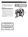 5
5
-
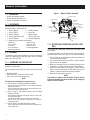 6
6
-
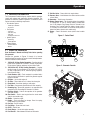 7
7
-
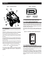 8
8
-
 9
9
-
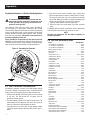 10
10
-
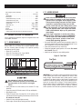 11
11
-
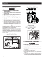 12
12
-
 13
13
-
 14
14
-
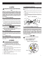 15
15
-
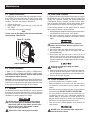 16
16
-
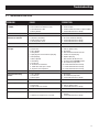 17
17
-
 18
18
-
 19
19
-
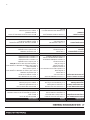 20
20
-
 21
21
-
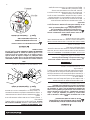 22
22
-
 23
23
-
 24
24
-
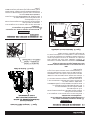 25
25
-
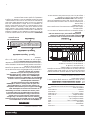 26
26
-
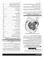 27
27
-
 28
28
-
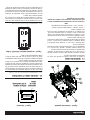 29
29
-
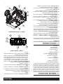 30
30
-
 31
31
-
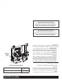 32
32
-
 33
33
-
 34
34
-
 35
35
-
 36
36


Generac GP5500 005939R5 Manual de usuario
- Categoría
- Generadores de poder
- Tipo
- Manual de usuario
en otros idiomas
- English: Generac GP5500 005939R5 User manual