Pioneer deh-p9600mp El manual del propietario
- Categoría
- Sistemas de video del coche
- Tipo
- El manual del propietario
La página se está cargando...

Nota:
• Antes de finalmente instalar la unidad, conecte el
cableado temporalmente y asegúrese de que todo
esté conectado correctamente y que la unidad y
el sistema funcionan debidamente.
• Utilice sólo las piezas que se incluyen con esta
unidad para asegurar la instalación adecuada. El
uso de piezas no autorizadas podría causar fallos
de funcionamiento.
• Consulte con su distribuidor si la instalación
requiere del taladro de orificios u otras modifica-
ciones del vehículo.
• Instale la unidad donde no alcance el espacio del
conductor, y donde no pueda dañar a los
pasajeros si sucediera un paro repentino, como
una detención de emergencia.
• El semiconductor láser se dañará si se sobre-
calienta, por eso no instale la unidad en un lugar
caliente – por ejemplo, cerca de la salida de un
calefactor.
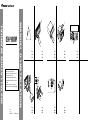
• Si el ángulo de la instalación excede los 60° del
lado horizontal, la unidad podría no brindar su
óptimo funcionamiento. (Fig. 1)
Montaje delantero/trasero DIN
Esta unidad quede instalarse correstamente de la
“Delantera” (montaje delantero DIN convenciona)
o “Trasera” (montaje trasero DIN, utilizando los
tornillos roscados en los constados del chasis de
la unidad). Para detalles, refiérase a los métodos
de instalación ilustrados abajo.
Montaje delantero DIN
Instalación con tope de goma (Fig. 2)
1. Tablero de instrumentos
2. Soporte
Después de insertar el soporte en la tabla de
mandos, luego seleccione las orejetas apropiadas
según el grosor del material de la tabla de man-
dos y dóblelos.
(Instale lo más firme posible usando las lengüe-
tas superior e inferior. Para fijar, doble las
lengüetas 90 grados.)
3. Tope de goma
4. Tornillo
Quitado de la unidad (Fig. 3) (Fig. 4)
5. Marco
6. Inserte el pasador de liberanción en el orificio de
la parte inferior del marco, y tire hacia afuera
para extraer el marco.
(Para la fijación del marco, apunte el lado con
ranura hacia abajo.)
7. Inserte las herramientas de extracción suminis-
tradas en la unidad, como se indica en la figura,
hasta que se enganchen en su positión.
Tire de la unidad mientras mantiene las her-
ramientas presionadas contra los lados de la
unidad.
Instalación <ESPAÑOL>
Montaje trasero DIN
Instalación usando los agujeros para
tornillos ubicados en ambos costados de
la unidad (Fig. 5) (Fig. 6) (Fig. 7)
1. Quite el marco.
8. Marco
9. Inserte el pasador de liberanción en el orificio de
la parte inferior del marco, y tire hacia afuera
para extaer el marco.
(Para la fijación del marco, apunte el lado con
ranura hacia abajo.)
2. Fijación de la unidad a la ménsula
de montaje existente.
10. Seleccione una posición en la que los orificios
para los tornillos del soporte y del de la unidad
principal queden alineados, y apriete los tornillos
en 2 lugares de un lado. Utilice ya sea los tornil-
los de fijación (5 × 6 mm) o los tornillos a paño
(5 × 6 mm), dependiendo de la forma de los ori-
ficios de tornillo en la ménsula.
11. Tornillo
12. Ménsula de montaje de radio existente
13. Tablero de instrumentos o consola
Conmutación del modo de ajuste
de DSP (Fig. 8)
Este producto brinda dos modos de operación: el
modo de red de 3 vías (NW) y el modo estándar
(STD). Podrá cambiar entre los modos según se
desee. Inicialmente, el ajuste de DSP se encuen-
tra configurado en el modo estándar (STD).
• Después de la conexión, reinicialice
el microprocesador. (Refiérase al
manual de operación.)
• Utilice un destornillador de punta
delgada estándar para conectar el
conmutador de DSP en la parte infe-
rior de este producto.
Colocación del panel delantero
(Fig. 9)
Si no se opera la remoción y fijación de la fun-
ción del panel delantero, utilice los tornillos de
fijación suministrados para fijar el panel
delantero a esta unidad.
14. Tornillos de fijación
DIN Rear-mount
Installation using the screw holes on the
side of the unit (Fig. 5) (Fig. 6) (Fig. 7)
1. Remove the frame.
8. Frame
9. Insert the release pin into the hole in the bottom
of the frame and pull out to remove the frame.
(When reattaching the frame, point the side with
a groove downwards and attach it.)
2. Fastening the unit to the factory
radio mounting bracket.
10. Select a position where the screw holes of the
bracket and the screw holes of the head unit
become aligned (are fitted), and tighten the
screws at 2 places on each side. Use either bind-
ing screws (5 × 6 mm) or flush surface screws
(5 × 6 mm), depending on the shape of the screw
holes in the bracket.
11. Screw
12. Factory radio mounting bracket
13. Dashboard or Console
Switching the DSP setting mode
(Fig. 8)
This product features two operation modes: the
3-way network mode (NW) and the standard
mode (STD). You can switch between modes as
desired. Initially, the DSP setting is set to the
standard mode (STD).
• After switching, reset the micro-
processor. (Refer to operation manu-
al.)
• Use a thin standard tip screwdriver
to switch the DSP switch on the bot-
tom of this product.
Fixing the front panel (Fig. 9)
If you do not operate the removing and attaching
the front panel function, use the supplied fixing
screws to fix the front panel to this unit.
14. Fixing screw
Note:
• Before finally installing the unit, connect the
wiring temporarily, making sure it is all connect-
ed up properly, and the unit and the system work
properly.
• Use only the parts included with the unit to
ensure proper installation. The use of unautho-
rized parts can cause malfunctions.
• Consult with your nearest dealer if installation
requires the drilling of holes or other modifica-
tions of the vehicle.
• Install the unit where it does not get in the dri-
ver’s way and cannot injure the passenger if there
is a sudden stop, like an emergency stop.
• The semiconductor laser will be damaged if it
overheats, so don’t install the unit anywhere hot
— for instance, near a heater outlet.
• If installation angle exceeds 60° from horizontal,
the unit might not give its optimum performance.
(Fig. 1)
DIN Front/Rear-mount
This unit can be properly installed either from
“Front” (conventional DIN Front-mount) or
“Rear” (DIN Rear-mount installation, utilizing
threaded screw holes at the sides of unit chassis).
For details, refer to the following illustrated
installation methods.
DIN Front-mount
Installation with the rubber bush (Fig. 2)
1. Dashboard
2. Holder
After inserting the holder into the dashboard,
then select the appropriate tabs according to the
thickness of the dashboard material and bend
them.
(Install as firmly as possible using the top and
bottom tabs. To secure, bend the tabs 90
degrees.)
3. Rubber bush
4. Screw
Removing the Unit (Fig. 3) (Fig. 4)
5. Frame
6. Insert the release pin into the hole in the bottom
of the frame and pull out to remove the frame.
(When reattaching the frame, point the side with
a groove downwards and attach it.)
7. Insert the supplied extraction keys into the unit,
as shown in the figure, until they click into place.
Keeping the keys pressed against the sides of the
unit, pull the unit out.
Installation <ENGLISH>
La página se está cargando...
La página se está cargando...
La página se está cargando...

• Cords for this product and those for other prod-
ucts may be different colors even if they have
the same function. When connecting this prod-
uct to another product, refer to the supplied
manuals of both products and connect cords that
have the same function.
Note:
• This unit is for vehicles with a 12-volt battery
and negative grounding. Before installing it in a
recreational vehicle, truck, or bus, check the bat-
tery voltage.
• To avoid shorts in the electrical system, be sure
to disconnect the ≠ battery cable before begin-
ning installation.
• Refer to the owner’s manual for details on con-
necting the power amp and other units, then
make connections correctly.
• Secure the wiring with cable clamps or adhesive
tape. To protect the wiring, wrap adhesive tape
around them where they lie against metal parts.
• Route and secure all wiring so it cannot touch
any moving parts, such as the gear shift, hand-
brake and seat rails. Do not route wiring in
places that get hot, such as near the heater outlet.
If the insulation of the wiring melts or gets torn,
there is a danger of the wiring short-circuiting to
the vehicle body.
• Don’t pass the yellow lead through a hole into
the engine compartment to connect to the battery.
This will damage the lead insulation and cause a
very dangerous short.
• Do not shorten any leads. If you do, the protec-
tion circuit may fail to work when it should.
• Never feed power to other equipment by cutting
the insulation of the power supply lead of the
unit and tapping into the lead. The current capac-
ity of the lead will be exceeded, causing over-
heating.
• When replacing fuse, be sure to use only fuse of
the rating prescribed on the fuse holder.
• Since a unique BPTL circuit is employed, never
wire so the speaker leads are directly grounded
or the left and right ≠ speaker leads are com-
mon.
• If the RCA pin jack on the unit will not be used,
do not remove the caps attached to the end of the
connector.
• Speakers connected to this unit must be high-
power types with minimum rating of 50 W and
impedance of 4 to 8 ohms. Connecting speakers
with output and/or impedance values other than
those noted here may result in the speakers
catching fire, emitting smoke or becoming dam-
aged.
• When this product’s source is switched ON, a
control signal is output through the blue/white
lead. Connect to an external power amp’s system
remote control or the car’s Auto-antenna relay
control terminal (max. 300 mA 12 V DC). If the
car features a glass antenna, connect to the anten-
na booster power supply terminal.
• When an external power amp is being used with
this system, be sure not to connect the blue/white
lead to the amp’s power terminal. Likewise, do
not connect the blue/white lead to the power ter-
minal of the auto-antenna. Such connection could
cause excessive current drain and malfunction.
• To avoid short-circuiting, cover the disconnected
lead with insulating tape. Especially, insulate the
unused speaker leads without fail. There is a pos-
sibility of short-circuiting if the leads are not
insulated.
• To prevent incorrect connection, the input side of
the IP-BUS connector is blue, and the output side
is black. Connect the connectors of the same col-
ors correctly.
• If this unit is installed in a vehicle that does not
have an ACC (accessory) position on the ignition
switch, the red lead of the unit should be con-
nected to a terminal coupled with ignition switch
ON/OFF operations. If this is not done, the vehi-
cle battery may be drained when you are away
from the vehicle for several hours.
• The black lead is ground. Please ground this lead
separately from the ground of high-current prod-
ucts such as power amps.
If you ground the products together and the
ground becomes detached, there is a risk of dam-
age to the products or fire.
Connecting the Units <ENGLISH>
ACC position
A
C
C
O
N
S
T
A
R
T
O
F
F
O
N
S
T
A
R
T
O
F
F
No ACC position
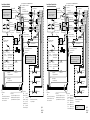
Connection Diagram
Connection diagram for standard mode
(Fig. 10)
Connection diagram for 3-way network
mode (Fig. 11)
1. TEL terminal (TEL)
Refer to handsfree telephone unit’s mamual (sold
separately).
2. Antenna jack
3. This product
4. DSP switch
Switch the DSP switch as illustration below.
5. IP-BUS input (Blue)
6. Multi-CD player (sold separately)
7. IP-BUS cable
8. Jack for the Wired Remote Control (WIRED
REMOTE INPUT)
Refer to Wired Remote Control’s manual (sold
separately).
9. Subwoofer output (LOW/SUBWOOFER OUT-
PUT)
10. Rear output (MID/REAR OUTPUT)
11. Front output (HIGH/FRONT OUTPUT)
12. Note:
Depending on the kind of vehicle, the function of
3* and 5* may be different. In this case, be sure
to connect 2* to 5* and 4* to 3*.
13. Connect leads of the same color to each other.
14. Cap (1*)
When not using this terminal, do not remove the
cap.
15. Yellow (3*)
Back-up (or accessory)
16. Yellow (2*)
To terminal always supplied with power regard-
less of ignition switch position.
17. Fuse holder
18. Red (5*)
Accessory (or back-up)
19. Red (4*)
To electric terminal controlled by ignition switch
(12 V DC) ON/OFF.
20. Fuse resistor
21. Orange/white
To lighting switch terminal.
22. Black (ground)
To vehicle (metal) body.
23. ISO connector
Note:
In some vehicles, the ISO connector may be
divided into two. In this case, be sure to connect
to both connectors.
24. Yellow/black
If you use a cellular telephone, connect it via the
Audio Mute lead on the cellular telephone. If not,
keep the Audio Mute lead free of any connec-
tions.
25. Speaker leads
White :Front left +
White/black :Front left ≠
Gray :Front right +
Gray/black :Front right ≠
Green :Rear left +
Green/black :Rear left ≠
Violet :Rear right +
Violet/black :Rear right ≠
26. Connecting cords with RCA pin plugs (sold
separately)
27. Power amp (sold separately)
28. Blue/white
To system control terminal of the power amp
(max. 300 mA 12 V DC).
29. System remote control
30. Blue/white (7*)
To Auto-antenna relay control terminal
(max. 300 mA 12 V DC).
31. Blue/white (6*)
32. The pin position of the ISO connector will differ
depends on the type of vehicle. Connect 6* and
7* when Pin 5 is an antenna control type. In
another type of vehicle, never connect 6* and 7*.
33. Left
34. Right
35. Front speaker
36. Rear speaker
37. Subwoofer
38. Perform these connections when using the
optional amplifier.
39. Low range output (LOW/SUBWOOFER OUT-
PUT)
40. Middle range output (MID/REAR OUTPUT)
41. High range output (HIGH/FRONT OUTPUT)
42. Speaker leads
White : High range left +
White/black : High range left ≠
Gray : High range right +
Gray/black : High range right ≠
Green : Middle range left +
Green/black : Middle range left ≠
Violet : Middle range right +
Violet/black : Middle range right ≠
43. High range speaker
44. Middle range speaker
45. Low range speaker
46. External amp is required for connecting the low
range speaker.
Nota:
• Esta unidad es para vehículos con batería de 12
voltios y con conexión a tierra. Antes de instalar la
unidad en un vehículo recreativo, camioneta, o
autobús, revise el voltaje de la batería.
• Para evitar cortocircuitos en el sistema eléctrico,
asegúrese de desconectar el cable de la batería ≠
antes de comenzar con la instalación.
• Consulte con el manual del usuario para los
detalles sobre la conexión de la alimentación de
amperios y de otras unidades, luego haga las
conexiones correctamente.
• Asegure el cableado con abrazaderas de cables o
con cinta adhesiva. Para proteger el cableado,
envuélvalo con cinta adhesiva donde éstos se
apoyan sobre las piezas de metal.
• Coloque y asegure todo el cableado de tal manera
que no toque las piezas en movimiento, tal como la
palanca de cambio de velocidades, el freno de
mano, y los pasamanos de los asientos. No coloque
el cableado en lugares que se calientan, tal como
cerca de la salida de un calefactor. Si el material
aislante del cableado se derritiera o se gastara,
habrá el peligro de un cortocircuito del cableado a
la carrocería del vehículo.
• No pase el conductor amarillo a través de un orifi-
cio en el compartimiento del motor para conectar a
la batería. Esto dañará el material aislante del con-
ductor y causará un cortocircuito peligroso.
• No acorte ningún conductor. Si lo hiciera, la pro-
tección del circuito podría fallar al funcionar
cuando debería.
• Nunca alimente energía a otros equipos cortando el
aislamiento del conductor de alimentación provista
de la unidad y haciendo un empalme con el con-
ductor. La capacidad de corriente del conductor se
excederá, causando el recalentamiento.
• Cuando reemplace algún fusible, asegúrese de
utilizar solamente un fusible del ratio descrito en
el soporte de fusibles.
• Ya que se emplea un circuito único BPTL, nunca
coloque los cables de manera que los conductores
del altavoz estén directamente en conexión a tierra
o que el altavoz izquierdo y derecho ≠ sean
comunes.
• Si la toma de clavija RCA en la unidad no se usa,
retire las tapas fijadas al extremo del conector.
• Los altavoces conectados a esta unidad deberán ser
del tipo de alta potencia, teniendo un régimen
mínimo de 50 W y una impedancia de 4 a 8
ohmios. La conexión de altavoces con valores de
impedancia y/o de salida diferentes a los anotados
aquí podrían causar fuego, emisión de humo o
daños a los altavoces.
• Cuando se conecta la fuente de este producto, una
señal de control se emite a través del conductor
azul/blanco. Conecte al control remoto de sistema
de un amplificador de potencia externo o al termi-
nal de controle de relé de antena automática del
vehículo (máx. 300 mA 12 V CC). Si el vehículo
tiene una antena en vidrio, conecte al terminal de
suministro de energía de la antena.
• Cuando se está utilizando un amperio de potencia
externa con este sistema, asegúrese de no conectar
el conductor azul/blanco al terminal de potencia de
amperios. Asimismo, no conecte el conductor
azul/blanco al terminal de potencia de la auto-ante-
na. Tal conexión podría causar la fuga de corriente
excesiva y causar fallos de funcionamiento.
• Para evitar cortocircuitos, cubra el conductor
desconectado con cinta aislada. Especialmente,
aísle los conductores de altavoz no usados. Hay la
posibilidad de cortocircuito si no se aíslan los
conductores.
• Para evitar la conexión incorrecta, el lado de entra-
da del conector IP-BUS es azul, y el lado de salida
es negro. Conecte los conectores del mismo color
correctamente.
• Si se instala esta unidad en un vehículo que no
tiene una posición ACC (accesorio) en el interrup-
tor de encendido, el conductor rojo de la unidad
deberá conectarse al terminal conectado con las
operaciones del interruptor de encendido ON/OFF.
Si no se hace esto, la batería del vehículo podría
drenarse cuando usted esté lejos del vehículo por
varias horas.
• El conductor negro es la masa. Conecte a masa
este conductor separadamente desde la masa de
los productos de alta corriente tal como los
amplificadores de potencia.
Si conecta juntos a masa los productos y la masa
se desconecta, se crea el riesgo de daños a los
productos o de incendios.
• Los cables para este producto y aquéllas para
otros productos pueden ser de colores diferentes
aun si tienen la misma función. Cuando se
conecta este producto a otro, refiérase a los
manuales de ambos productos y conecte los
cables que tienen la misma función.
Conexión de las unidades <ESPAÑOL>
Posición ACC
A
C
C
O
N
S
T
A
R
T
O
F
F
O
N
S
T
A
R
T
O
F
F
No en la posición ACC
Diagrama de conexión
Diagrama de conexiones para el modo
estándar (Fig. 10)
Diagrama de conexiones para el modo de
red de 3 vías (Fig. 11)
1. Terminal TEL (TEL)
Refiérase al manual del usuario del teléfono de
manos libres (en venta por separado).
2. Jack para antena
3. Este producto
4. Conmutator de DSP
Conecte el conmutador de DSP de acuerdo con la
siguiente ilustración.
5. Entrada IP-BUS (Azul)
6. Reproductor de Multi-CD (en venta por
separado)
7. Cable IP-BUS
8. Toma para el control remoto con hilo (WIRED
REMOTE INPUT)
Consulte el manual de instrucciones para el con-
trol remoto con hilo (en venta por separado).
9. Salida de altavoz de graves secundario
(LOW/SUBWOOFER OUTPUT)
10. Salida trasera (MID/REAR OUTPUT)
11. Salida delantera (HIGH/FRONT OUTPUT)
12. Nota:
Dependiendo del tipo del vehículo, la función de
3* y 5* puede ser diferente. En este caso,
asegúrese de conectar 2* a 5* y 4* a 3*.
13. Conecte los conductores del mismo color uno a
otro.
14. Tapa (1*)
Cuando este terminal no se usa, no retire la tapa.
15. Amarillo (3*)
Reserva (o accesorio)
16. Amarillo (2*)
Al terminal con suministro constante de
electricidad, independientemente de la posición
del interruptor de encendido.
17. Portafusible
18. Rojo (5*)
Accesorio (o reserva)
19. Rojo (4*)
Al terminal de energía eléctrica controlado por el
interruptor de encendido del vehículo (12 V CC)
ON/OFF.
20. Resistencia de fusible
21. Anaranjado/blanco
Al terminal de interruptor de iluminación.
22. Negro (masa)
A la carrocería del vehículo (parte metálica).
23. Conector ISO
Nota:
En algunos vehículos, el conector ISO puede
estar dividido en dos partes. En este caso,
asegúrese de conectar a ambos conectores.
24. Amarillo/negro
Si utiliza un teléfono celular, conéctelo por el
cable de enmudecimiento de audio del teléfono
celular. Si no, mantenga el enmudecimiento de
audio libre de cualquier conexión.
25. Cables de altavoz
Blanco : Izquierdo delantero +
Blanco/negro: Izquierdo delantero ≠
Gris : Derecho delantero +
Gris/negro : Derecho delantero ≠
Verde : Izquierdo trasero +
Verde/negro : Izquierdo trasero ≠
Violeta : Derecho trasero +
Violeta/negro: Derecho trasero ≠
26. Cables de conexión con clavijás RCA (en venta
por separado)
27. Amplificador de potencia (en venta por separado)
28. Azul/blanco
Al terminal de control del sistema del amplifi-
cador de potencia (máx. 300 mA 12 V CC).
29. Control remoto de sistema
30. Azul/blanco (7*)
Al terminal de control de relé de antena
automática (máx. 300 mA 12 V CC).
31. Azul/blanco (6*)
32. La posición de los pinos del conector ISO difiere
de acuerdo al tipo de vehículo. Conecte 6* y 7*
cuando el pino 5 es un tipo de control de antena.
En otros tipos de vehículo, nunca conecte 6* y
7*.
33. Izquierda
34. Derecha
35. Altavoz delantero
36. Altavoz trasero
37. Altavoz secundario
38. Lleve a cabo estas conexiones cuando utilice el
amplificador opcional.
39. Salida de rango bajo (LOW/SUBWOOFER
OUTPUT)
40. Salida de rango medio (MID/REAR OUTPUT)
41. Salida de rango alto (HIGH/FRONT OUTPUT)
42. Cables de altavoz
Blanco : Rango alto izquierdo +
Blanco/negro: Rango alto izquierdo ≠
Gris : Rango alto derecho +
Gris/negro : Rango alto derecho ≠
Verde : Rango medio izquierdo +
Verde/negro : Rango medio izquierdo ≠
Violeta : Rango medio derecho +
Violeta/negro: Rango medio derecho ≠
43. Altavoz de rango alto
44. Altavoz de rango medio
45. Altavoz de rango bajo
46. Para la conexión del altavoz de rango bajo, se
requiere un amplificador externo.
La página se está cargando...
La página se está cargando...
Transcripción de documentos
Installation Note: • • • • • • Before finally installing the unit, connect the wiring temporarily, making sure it is all connected up properly, and the unit and the system work properly. Use only the parts included with the unit to ensure proper installation. The use of unauthorized parts can cause malfunctions. Consult with your nearest dealer if installation requires the drilling of holes or other modifications of the vehicle. Install the unit where it does not get in the driver’s way and cannot injure the passenger if there is a sudden stop, like an emergency stop. The semiconductor laser will be damaged if it overheats, so don’t install the unit anywhere hot — for instance, near a heater outlet. If installation angle exceeds 60° from horizontal, the unit might not give its optimum performance. (Fig. 1) <ENGLISH> DIN Front/Rear-mount This unit can be properly installed either from “Front” (conventional DIN Front-mount) or “Rear” (DIN Rear-mount installation, utilizing threaded screw holes at the sides of unit chassis). For details, refer to the following illustrated installation methods. DIN Front-mount Installation with the rubber bush (Fig. 2) 1. Dashboard 2. Holder After inserting the holder into the dashboard, then select the appropriate tabs according to the thickness of the dashboard material and bend them. (Install as firmly as possible using the top and bottom tabs. To secure, bend the tabs 90 degrees.) 3. Rubber bush 4. Screw DIN Rear-mount Fixing the front panel (Fig. 9) Installation using the screw holes on the side of the unit (Fig. 5) (Fig. 6) (Fig. 7) If you do not operate the removing and attaching the front panel function, use the supplied fixing screws to fix the front panel to this unit. 14. Fixing screw 1. Remove the frame. 8. Frame 9. Insert the release pin into the hole in the bottom of the frame and pull out to remove the frame. (When reattaching the frame, point the side with a groove downwards and attach it.) 2. Fastening the unit to the factory radio mounting bracket. 10. Select a position where the screw holes of the bracket and the screw holes of the head unit become aligned (are fitted), and tighten the screws at 2 places on each side. Use either binding screws (5 × 6 mm) or flush surface screws (5 × 6 mm), depending on the shape of the screw holes in the bracket. 11. Screw 12. Factory radio mounting bracket 13. Dashboard or Console Instalación Nota: • • • • • • Antes de finalmente instalar la unidad, conecte el cableado temporalmente y asegúrese de que todo esté conectado correctamente y que la unidad y el sistema funcionan debidamente. Utilice sólo las piezas que se incluyen con esta unidad para asegurar la instalación adecuada. El uso de piezas no autorizadas podría causar fallos de funcionamiento. Consulte con su distribuidor si la instalación requiere del taladro de orificios u otras modificaciones del vehículo. Instale la unidad donde no alcance el espacio del conductor, y donde no pueda dañar a los pasajeros si sucediera un paro repentino, como una detención de emergencia. El semiconductor láser se dañará si se sobrecalienta, por eso no instale la unidad en un lugar caliente – por ejemplo, cerca de la salida de un calefactor. Si el ángulo de la instalación excede los 60° del lado horizontal, la unidad podría no brindar su óptimo funcionamiento. (Fig. 1) <ESPAÑOL> Montaje delantero/trasero DIN Esta unidad quede instalarse correstamente de la “Delantera” (montaje delantero DIN convenciona) o “Trasera” (montaje trasero DIN, utilizando los tornillos roscados en los constados del chasis de la unidad). Para detalles, refiérase a los métodos de instalación ilustrados abajo. Montaje delantero DIN Instalación con tope de goma (Fig. 2) 1. Tablero de instrumentos 2. Soporte Después de insertar el soporte en la tabla de mandos, luego seleccione las orejetas apropiadas según el grosor del material de la tabla de mandos y dóblelos. (Instale lo más firme posible usando las lengüetas superior e inferior. Para fijar, doble las lengüetas 90 grados.) 3. Tope de goma 4. Tornillo Removing the Unit (Fig. 3) (Fig. 4) 5. Frame 6. Insert the release pin into the hole in the bottom of the frame and pull out to remove the frame. (When reattaching the frame, point the side with a groove downwards and attach it.) 7. Insert the supplied extraction keys into the unit, as shown in the figure, until they click into place. Keeping the keys pressed against the sides of the unit, pull the unit out. Switching the DSP setting mode (Fig. 8) This product features two operation modes: the 3-way network mode (NW) and the standard mode (STD). You can switch between modes as desired. Initially, the DSP setting is set to the standard mode (STD). • After switching, reset the microprocessor. (Refer to operation manual.) • Use a thin standard tip screwdriver to switch the DSP switch on the bottom of this product. Quitado de la unidad (Fig. 3) (Fig. 4) 5. Marco 6. Inserte el pasador de liberanción en el orificio de la parte inferior del marco, y tire hacia afuera para extraer el marco. (Para la fijación del marco, apunte el lado con ranura hacia abajo.) 7. Inserte las herramientas de extracción suministradas en la unidad, como se indica en la figura, hasta que se enganchen en su positión. Tire de la unidad mientras mantiene las herramientas presionadas contra los lados de la unidad. Montaje trasero DIN Instalación usando los agujeros para tornillos ubicados en ambos costados de la unidad (Fig. 5) (Fig. 6) (Fig. 7) 1. Quite el marco. 8. Marco 9. Inserte el pasador de liberanción en el orificio de la parte inferior del marco, y tire hacia afuera para extaer el marco. (Para la fijación del marco, apunte el lado con ranura hacia abajo.) 2. Fijación de la unidad a la ménsula de montaje existente. 10. Seleccione una posición en la que los orificios para los tornillos del soporte y del de la unidad principal queden alineados, y apriete los tornillos en 2 lugares de un lado. Utilice ya sea los tornillos de fijación (5 × 6 mm) o los tornillos a paño (5 × 6 mm), dependiendo de la forma de los orificios de tornillo en la ménsula. 11. Tornillo 12. Ménsula de montaje de radio existente 13. Tablero de instrumentos o consola Conmutación del modo de ajuste de DSP (Fig. 8) Este producto brinda dos modos de operación: el modo de red de 3 vías (NW) y el modo estándar (STD). Podrá cambiar entre los modos según se desee. Inicialmente, el ajuste de DSP se encuentra configurado en el modo estándar (STD). • Después de la conexión, reinicialice el microprocesador. (Refiérase al manual de operación.) • Utilice un destornillador de punta delgada estándar para conectar el conmutador de DSP en la parte inferior de este producto. Colocación del panel delantero (Fig. 9) Si no se opera la remoción y fijación de la función del panel delantero, utilice los tornillos de fijación suministrados para fijar el panel delantero a esta unidad. 14. Tornillos de fijación <ENGLISH> • • • AC C O • • • • • • • • • • • • • • • Cuando se conecta la fuente de este producto, una señal de control se emite a través del conductor azul/blanco. Conecte al control remoto de sistema de un amplificador de potencia externo o al terminal de controle de relé de antena automática del vehículo (máx. 300 mA 12 V CC). Si el vehículo tiene una antena en vidrio, conecte al terminal de suministro de energía de la antena. Cuando se está utilizando un amperio de potencia externa con este sistema, asegúrese de no conectar el conductor azul/blanco al terminal de potencia de amperios. Asimismo, no conecte el conductor azul/blanco al terminal de potencia de la auto-antena. Tal conexión podría causar la fuga de corriente excesiva y causar fallos de funcionamiento. Para evitar cortocircuitos, cubra el conductor desconectado con cinta aislada. Especialmente, aísle los conductores de altavoz no usados. Hay la posibilidad de cortocircuito si no se aíslan los conductores. Para evitar la conexión incorrecta, el lado de entrada del conector IP-BUS es azul, y el lado de salida es negro. Conecte los conectores del mismo color correctamente. Si se instala esta unidad en un vehículo que no tiene una posición ACC (accesorio) en el interruptor de encendido, el conductor rojo de la unidad deberá conectarse al terminal conectado con las operaciones del interruptor de encendido ON/OFF. Si no se hace esto, la batería del vehículo podría drenarse cuando usted esté lejos del vehículo por varias horas. F AC C O Posición ACC F O STAR Cords for this product and those for other products may be different colors even if they have the same function. When connecting this product to another product, refer to the supplied manuals of both products and connect cords that have the same function. • Esta unidad es para vehículos con batería de 12 voltios y con conexión a tierra. Antes de instalar la unidad en un vehículo recreativo, camioneta, o autobús, revise el voltaje de la batería. Para evitar cortocircuitos en el sistema eléctrico, asegúrese de desconectar el cable de la batería ≠ antes de comenzar con la instalación. Consulte con el manual del usuario para los detalles sobre la conexión de la alimentación de amperios y de otras unidades, luego haga las conexiones correctamente. Asegure el cableado con abrazaderas de cables o con cinta adhesiva. Para proteger el cableado, envuélvalo con cinta adhesiva donde éstos se apoyan sobre las piezas de metal. Coloque y asegure todo el cableado de tal manera que no toque las piezas en movimiento, tal como la palanca de cambio de velocidades, el freno de mano, y los pasamanos de los asientos. No coloque el cableado en lugares que se calientan, tal como cerca de la salida de un calefactor. Si el material aislante del cableado se derritiera o se gastara, habrá el peligro de un cortocircuito del cableado a la carrocería del vehículo. No pase el conductor amarillo a través de un orificio en el compartimiento del motor para conectar a la batería. Esto dañará el material aislante del conductor y causará un cortocircuito peligroso. No acorte ningún conductor. Si lo hiciera, la protección del circuito podría fallar al funcionar cuando debería. Nunca alimente energía a otros equipos cortando el aislamiento del conductor de alimentación provista de la unidad y haciendo un empalme con el conductor. La capacidad de corriente del conductor se excederá, causando el recalentamiento. Cuando reemplace algún fusible, asegúrese de utilizar solamente un fusible del ratio descrito en el soporte de fusibles. Ya que se emplea un circuito único BPTL, nunca coloque los cables de manera que los conductores del altavoz estén directamente en conexión a tierra o que el altavoz izquierdo y derecho ≠ sean comunes. Si la toma de clavija RCA en la unidad no se usa, retire las tapas fijadas al extremo del conector. Los altavoces conectados a esta unidad deberán ser del tipo de alta potencia, teniendo un régimen mínimo de 50 W y una impedancia de 4 a 8 ohmios. La conexión de altavoces con valores de impedancia y/o de salida diferentes a los anotados aquí podrían causar fuego, emisión de humo o daños a los altavoces. N The black lead is ground. Please ground this lead separately from the ground of high-current products such as power amps. If you ground the products together and the ground becomes detached, there is a risk of damage to the products or fire. 1. TEL terminal (TEL) Refer to handsfree telephone unit’s mamual (sold separately). 2. Antenna jack 3. This product 4. DSP switch Switch the DSP switch as illustration below. 5. IP-BUS input (Blue) 6. Multi-CD player (sold separately) 7. IP-BUS cable 8. Jack for the Wired Remote Control (WIRED REMOTE INPUT) Refer to Wired Remote Control’s manual (sold separately). 9. Subwoofer output (LOW/SUBWOOFER OUTPUT) 10. Rear output (MID/REAR OUTPUT) 11. Front output (HIGH/FRONT OUTPUT) 12. Note: Depending on the kind of vehicle, the function of 3* and 5* may be different. In this case, be sure to connect 2* to 5* and 4* to 3*. 13. Connect leads of the same color to each other. 14. Cap (1*) When not using this terminal, do not remove the cap. 15. Yellow (3*) Back-up (or accessory) 16. Yellow (2*) To terminal always supplied with power regardless of ignition switch position. 17. Fuse holder 18. Red (5*) Accessory (or back-up) 19. Red (4*) To electric terminal controlled by ignition switch (12 V DC) ON/OFF. 20. Fuse resistor 21. Orange/white To lighting switch terminal. 22. Black (ground) To vehicle (metal) body. 23. ISO connector Note: In some vehicles, the ISO connector may be divided into two. In this case, be sure to connect to both connectors. • STAR • No ACC position Connection diagram for 3-way network mode (Fig. 11) Nota: N • O STAR ACC position F N • F STAR • • N • • Connection diagram for standard mode (Fig. 10) 24. Yellow/black If you use a cellular telephone, connect it via the Audio Mute lead on the cellular telephone. If not, keep the Audio Mute lead free of any connections. 25. Speaker leads White :Front left + White/black :Front left ≠ Gray :Front right + Gray/black :Front right ≠ Green :Rear left + Green/black :Rear left ≠ Violet :Rear right + Violet/black :Rear right ≠ 26. Connecting cords with RCA pin plugs (sold separately) 27. Power amp (sold separately) 28. Blue/white To system control terminal of the power amp (max. 300 mA 12 V DC). 29. System remote control 30. Blue/white (7*) To Auto-antenna relay control terminal (max. 300 mA 12 V DC). 31. Blue/white (6*) 32. The pin position of the ISO connector will differ depends on the type of vehicle. Connect 6* and 7* when Pin 5 is an antenna control type. In another type of vehicle, never connect 6* and 7*. 33. Left 34. Right 35. Front speaker 36. Rear speaker 37. Subwoofer 38. Perform these connections when using the optional amplifier. 39. Low range output (LOW/SUBWOOFER OUTPUT) 40. Middle range output (MID/REAR OUTPUT) 41. High range output (HIGH/FRONT OUTPUT) 42. Speaker leads White : High range left + White/black : High range left ≠ Gray : High range right + Gray/black : High range right ≠ Green : Middle range left + Green/black : Middle range left ≠ Violet : Middle range right + Violet/black : Middle range right ≠ 43. High range speaker 44. Middle range speaker 45. Low range speaker 46. External amp is required for connecting the low range speaker. OF • • Connection Diagram OF • OF • • When this product’s source is switched ON, a control signal is output through the blue/white lead. Connect to an external power amp’s system remote control or the car’s Auto-antenna relay control terminal (max. 300 mA 12 V DC). If the car features a glass antenna, connect to the antenna booster power supply terminal. When an external power amp is being used with this system, be sure not to connect the blue/white lead to the amp’s power terminal. Likewise, do not connect the blue/white lead to the power terminal of the auto-antenna. Such connection could cause excessive current drain and malfunction. To avoid short-circuiting, cover the disconnected lead with insulating tape. Especially, insulate the unused speaker leads without fail. There is a possibility of short-circuiting if the leads are not insulated. To prevent incorrect connection, the input side of the IP-BUS connector is blue, and the output side is black. Connect the connectors of the same colors correctly. If this unit is installed in a vehicle that does not have an ACC (accessory) position on the ignition switch, the red lead of the unit should be connected to a terminal coupled with ignition switch ON/OFF operations. If this is not done, the vehicle battery may be drained when you are away from the vehicle for several hours. OF • • T • This unit is for vehicles with a 12-volt battery and negative grounding. Before installing it in a recreational vehicle, truck, or bus, check the battery voltage. To avoid shorts in the electrical system, be sure to disconnect the ≠ battery cable before beginning installation. Refer to the owner’s manual for details on connecting the power amp and other units, then make connections correctly. Secure the wiring with cable clamps or adhesive tape. To protect the wiring, wrap adhesive tape around them where they lie against metal parts. Route and secure all wiring so it cannot touch any moving parts, such as the gear shift, handbrake and seat rails. Do not route wiring in places that get hot, such as near the heater outlet. If the insulation of the wiring melts or gets torn, there is a danger of the wiring short-circuiting to the vehicle body. Don’t pass the yellow lead through a hole into the engine compartment to connect to the battery. This will damage the lead insulation and cause a very dangerous short. Do not shorten any leads. If you do, the protection circuit may fail to work when it should. Never feed power to other equipment by cutting the insulation of the power supply lead of the unit and tapping into the lead. The current capacity of the lead will be exceeded, causing overheating. When replacing fuse, be sure to use only fuse of the rating prescribed on the fuse holder. Since a unique BPTL circuit is employed, never wire so the speaker leads are directly grounded or the left and right ≠ speaker leads are common. If the RCA pin jack on the unit will not be used, do not remove the caps attached to the end of the connector. Speakers connected to this unit must be highpower types with minimum rating of 50 W and impedance of 4 to 8 ohms. Connecting speakers with output and/or impedance values other than those noted here may result in the speakers catching fire, emitting smoke or becoming damaged. T • <ESPAÑOL> T Note: Conexión de las unidades T Connecting the Units No en la posición ACC • El conductor negro es la masa. Conecte a masa este conductor separadamente desde la masa de los productos de alta corriente tal como los amplificadores de potencia. Si conecta juntos a masa los productos y la masa se desconecta, se crea el riesgo de daños a los productos o de incendios. • Los cables para este producto y aquéllas para otros productos pueden ser de colores diferentes aun si tienen la misma función. Cuando se conecta este producto a otro, refiérase a los manuales de ambos productos y conecte los cables que tienen la misma función. Diagrama de conexión Diagrama de conexiones para el modo estándar (Fig. 10) Diagrama de conexiones para el modo de red de 3 vías (Fig. 11) 1. Terminal TEL (TEL) Refiérase al manual del usuario del teléfono de manos libres (en venta por separado). 2. Jack para antena 3. Este producto 4. Conmutator de DSP Conecte el conmutador de DSP de acuerdo con la siguiente ilustración. 5. Entrada IP-BUS (Azul) 6. Reproductor de Multi-CD (en venta por separado) 7. Cable IP-BUS 8. Toma para el control remoto con hilo (WIRED REMOTE INPUT) Consulte el manual de instrucciones para el control remoto con hilo (en venta por separado). 9. Salida de altavoz de graves secundario (LOW/SUBWOOFER OUTPUT) 10. Salida trasera (MID/REAR OUTPUT) 11. Salida delantera (HIGH/FRONT OUTPUT) 12. Nota: Dependiendo del tipo del vehículo, la función de 3* y 5* puede ser diferente. En este caso, asegúrese de conectar 2* a 5* y 4* a 3*. 13. Conecte los conductores del mismo color uno a otro. 14. Tapa (1*) Cuando este terminal no se usa, no retire la tapa. 15. Amarillo (3*) Reserva (o accesorio) 16. Amarillo (2*) Al terminal con suministro constante de electricidad, independientemente de la posición del interruptor de encendido. 17. Portafusible 18. Rojo (5*) Accesorio (o reserva) 19. Rojo (4*) Al terminal de energía eléctrica controlado por el interruptor de encendido del vehículo (12 V CC) ON/OFF. 20. Resistencia de fusible 21. Anaranjado/blanco Al terminal de interruptor de iluminación. 22. Negro (masa) A la carrocería del vehículo (parte metálica). 23. Conector ISO Nota: En algunos vehículos, el conector ISO puede estar dividido en dos partes. En este caso, asegúrese de conectar a ambos conectores. 24. Amarillo/negro Si utiliza un teléfono celular, conéctelo por el cable de enmudecimiento de audio del teléfono celular. Si no, mantenga el enmudecimiento de audio libre de cualquier conexión. 25. Cables de altavoz Blanco : Izquierdo delantero + Blanco/negro : Izquierdo delantero ≠ Gris : Derecho delantero + Gris/negro : Derecho delantero ≠ Verde : Izquierdo trasero + Verde/negro : Izquierdo trasero ≠ Violeta : Derecho trasero + Violeta/negro: Derecho trasero ≠ 26. Cables de conexión con clavijás RCA (en venta por separado) 27. Amplificador de potencia (en venta por separado) 28. Azul/blanco Al terminal de control del sistema del amplificador de potencia (máx. 300 mA 12 V CC). 29. Control remoto de sistema 30. Azul/blanco (7*) Al terminal de control de relé de antena automática (máx. 300 mA 12 V CC). 31. Azul/blanco (6*) 32. La posición de los pinos del conector ISO difiere de acuerdo al tipo de vehículo. Conecte 6* y 7* cuando el pino 5 es un tipo de control de antena. En otros tipos de vehículo, nunca conecte 6* y 7*. 33. Izquierda 34. Derecha 35. Altavoz delantero 36. Altavoz trasero 37. Altavoz secundario 38. Lleve a cabo estas conexiones cuando utilice el amplificador opcional. 39. Salida de rango bajo (LOW/SUBWOOFER OUTPUT) 40. Salida de rango medio (MID/REAR OUTPUT) 41. Salida de rango alto (HIGH/FRONT OUTPUT) 42. Cables de altavoz Blanco : Rango alto izquierdo + Blanco/negro : Rango alto izquierdo ≠ Gris : Rango alto derecho + Gris/negro : Rango alto derecho ≠ Verde : Rango medio izquierdo + Verde/negro : Rango medio izquierdo ≠ Violeta : Rango medio derecho + Violeta/negro: Rango medio derecho ≠ 43. Altavoz de rango alto 44. Altavoz de rango medio 45. Altavoz de rango bajo 46. Para la conexión del altavoz de rango bajo, se requiere un amplificador externo.-
 1
1
-
 2
2
-
 3
3
-
 4
4
-
 5
5
-
 6
6
-
 7
7
-
 8
8


Pioneer deh-p9600mp El manual del propietario
- Categoría
- Sistemas de video del coche
- Tipo
- El manual del propietario
en otros idiomas
- français: Pioneer deh-p9600mp Le manuel du propriétaire
- italiano: Pioneer deh-p9600mp Manuale del proprietario
- English: Pioneer deh-p9600mp Owner's manual
- Deutsch: Pioneer deh-p9600mp Bedienungsanleitung
- Nederlands: Pioneer deh-p9600mp de handleiding
Artículos relacionados
-
Pioneer DEH-3300R Guía de instalación
-
-
-
-
-
-
-
-
Pioneer DEH-P88RS-II Guía de instalación
-