Dixon D22KH46 (96046001200) El manual del propietario
- Categoría
- Tractor
- Tipo
- El manual del propietario
Este manual también es adecuado para

/
®
Operator's Manual
04.08.10 JA
43361 6 Rev. 1 PrintedintheU.S.A.

SAFETY RULES
Safe Operation Practices for Ride=On Mowers
DANGER: THiS CUTTING MACHINE iS CAPABLE OF AMPUTATING HANDS AND FEET AND THROWING OBJECTS. FAILURE
TO OBSERVE THE FOLLOWING SAFETY iNSTRUCTiONS COULD RESULT iN SERIOUS iNJURY OR DEATH.
WARNING: in orderto prevent accidental
starting when setting up, transporting,
adjusting or making repairs, always
disconnect spark plug wire and place
wire where it cannot contact spark plug.
WARNING: Do not coast down ahill in neu-tral, you may lose control of the tractor.
WARNING: Tow onlythe attachments that
are recommended by and comply with
specifications of the manufacturer of your
tractor. Use common sense when towing.
Operate only atthe lowest possible speed
when on a slope. Too heavy of a load,
while on a slope, is dangerous. Tires
can lose traction with the ground and
cause you to lose control of your tractor.
WARNING
Engine exhaust, some of itsconstituents, and certain
vehicle components contain or emit chemicals
known to the State of California to cause cancer
and birth defects or other reproductive harm.
WARNING
Battery posts, terminals and related accessories
contain lead and lead compounds, chemicals known
to the State of California to cause cancer and birth
defects or other reproductive harm. Wash hands
after handling.
I. GENERAL OPERATION
• Read, understand, and follow all instructions on the
machine and in the manual before starting.
• Do not put hands or feet near rotating parts or under
the machine. Keep clear of the discharge opening at
all times.
• Only allow responsible adults, who are familiar with
the instructions, to operate the machine.
• Clear the area of objects such as rocks, toys, wire, etc.,
which could be picked up and thrown by the blades.
• Be sure the area is clear of bystanders before
operating. Stop machine if anyone enters the area.
• Never carry passengers.
• Do not mow in reverse unless absolutely necessary.
Always look down and behind before and while
backing.
• Never direct discharged material toward anyone. Avoid
discharging material against a wall or obstruction.
Material may ricochet back toward the operator. Stop
the blades when crossing gravel surfaces.
• Do not operate machine without the entire grass catcher,
discharge chute, or other safety devices in place and
working.
• Slow down before turning.
• Never leave a running machine unattended. Always
turn off blades, set parking brake, stop engine, and
remove keys before dismounting.
• Disengage blades when not mowing. Shut off engine
and wait for all parts to come to a complete stop before
cleaning the machine, removing the grass catcher, or
unclogging the discharge chute.
• Operate machine only in daylight or good artificial
light.
• Do not operate the machine while under the influence
of alcohol or drugs.
• Watch for traffic when operating near or crossing
roadways.
• Use extra care when loading or unloading the machine
into a trailer or truck.
• Always wear eye protection when operating
machine.
• Data indicates that operators, age 60 years and above,
are involved in a large percentage of riding mower-
related injuries. These operators should evaluate their
ability to operate the riding mower safely enough to
protect themselves and others from serious injury.
• Follow the manufacturer's recommendation for wheel
weights or counterweights.
• Keep machine free of grass , leaves or other debris
build-up which can touch hot exhaust / engine parts
and burn. Do not allow the mower deck to plow leaves
or other debris which can cause build-up to occur.
Clean any oil or fuel spillage before operating or storing
the machine. Allow machine to cool before storage.
II. SLOPE OPERATION
Slopes are a major factor related to loss of control and
tip-over accidents, which can result in severe injury or
death. Operation on all slopes requires extra caution. If
you cannot back up the slope or if you feel uneasy on it,
do not mow it.
• Mow up and down slopes, not across.
• Watch for holes, ruts, bumps, rocks, or other hidden
objects. Uneven terrain could overturn the machine.
Tall grass can hide obstacles.
• Choose a low ground speed so that you will not have
to stop or shift while on the slope.
• Do not mow on wet grass. Tires may lose traction.
Always keep the machine in gear when going down
slopes. Do not shift to neutral and coast downhill.
• Avoid starting, stopping, or turning on a slope. If the
tires lose traction, disengage the blades and proceed
slowly straight down the slope.
• Keep all movement on the slopes slow and gradual.
Do not make sudden changes in speed or direction,
which could cause the machine to roll over.
• Use extra care while operating machine with grass
catchers or other attachments; they can affect the
stability of the machine. Do no use on steep slopes.
• Do not try to stabilize the machine by putting your foot
on the ground.
• Do not mow near drop-offs, ditches, or embankments.
The machine could suddenly roll over if a wheel isover
the edge or if the edge caves in.
2

SAFETY RULES
Safe Operation Practices for Ride=On Mowers
ill. CHILDREN
Tragic accidents can occur if the operator is not alert to
the presence of children. Children are often attracted to
the machine and the mowing activity. Never assume that
children will remain where you last saw them.
• Keepchildrenoutofthemowingareaandinthewatchful
care of a responsible adult other than the operator.
• Be alert and turn machine off if a child enters the
area.
• Before and while backing, look behind and down for
small children.
• Never carry children, even with the blades shut off. They
may fall off and be seriously injured or interfere with
safe machine operation. Children who have been given
rides in the past may suddenly appear in the mowing
area for another ride and be run over or backed over
by the machine.
• Never allow children to operate the machine.
• Use extra care when approaching blind corners, shrubs,
trees, or other objects that may block your view of a
child.
IV. TOWING
• Tow only with a machine that has a hitch designed for
towing. Do not attach towed equipment except at the
hitch point.
• Follow the manufacturer's recommendation for weight
limits for towed equipment and towing on slopes.
• Never allow children or others in or on towed
equipment.
• On slopes, the weight of the towed equipment may
cause loss of traction and loss of control.
• Travel slowly and allow extra distance to stop.
V. SERVICE
SAFE HANDLING OF GASOLINE
To avoid personal injuryor property damage, use extreme
care in handling gasoline. Gasoline isextremely flammable
and the vapors are explosive.
• Extinguish all cigarettes, cigars, pipes, and other
sources of ignition.
• Use only approved gasoline container.
• Never remove gas cap or add fuel with the engine
running. Allow engine to cool before refueling.
• Never fuel the machine indoors.
• Never store the machine or fuel container where there
isan open flame, spark, or pilot light such as on a water
heater or other appliances.
• Never fill containers inside a vehicle or on a truck or
trailer bed with plastic liner. Always place containers
on the ground away from your vehicle when filling.
• Remove gas-powered equipment from the truck or
trailer and refuel iton the ground. If this is not possible,
then refuel such equipment with a portable container,
rather than from a gasoline dispenser nozzle.
• Keep the nozzle incontact with the rim of the fuel tank or
container opening at all times until fueling is complete.
Do not use a nozzle lock-open device.
• If fuel is spilled on clothing, change clothing immedi-
ately.
• Never overfill fuel tank. Replace gas cap and tighten
securely.
GENERAL SERVICE
• Never operate machine in a closed area.
• Keep all nuts and bolts tight to be sure the equipment
is in safe working condition.
• Never tamper with safety devices. Check their proper
operation regularly.
• Keep machine free of grass, leaves, or other debris
build-up. Clean oil or fuel spillage and remove any fuel-
soaked debris. Allow machine to cool before storing.
• If you strike a foreign object, stop and inspect the
machine. Repair, if necessary, before restarting.
• Never make any adjustments or repairs with the engine
running.
• Check grass catcher components and the discharge
chute frequently and replace with manufacturer's rec-
ommended parts, when necessary.
• Mower blades are sharp. Wrap the blade or wear
gloves, and use extra caution when servicing them.
• Check brake operation frequently. Adjust and service
as required.
• Maintain or replace safety and instruction labels, as
necessary.
o
o
o
o
o
o
o
o
o
o
o
Be sure the area isclear of bystanders before operat-
ing. Stop machine ifanyone enters the area.
Never carry passengers.
Do not mow in reverse unless absolutely necessary.
Always look down and behind before and while back-
ing.
Never carry children, even with the blades shut off. They
may fall off and be seriously injured or interfere with
safe machine operation. Children who have been given
rides in the past may suddenly appear in the mowing
area for another ride and be run over or backed over
by the machine.
Keep children out ofthe mowing area and inthewatchful
care of a responsible adult other than the operator.
Be alert and turn machine off if a child enters the
area.
Before and while backing, look behind and down for
small children.
Mow up and down slopes (15° Max), not across.
Choose a low ground speed so that you will not have
to stop or shift while on the slope.
Avoid starting, stopping, or turning on a slope. If the
tires lose traction, disengage the blades and proceed
slowly straight down the slope.
If machine stops while going uphill, disengage blades,
shift into reverse and back down slowly.
Do not turn on slopes unless necessary, and then, turn
slowly and gradually downhill, if possible.
3

PRODUCT SPECiFiCATiONS
Gasoline Capacity 3 Gallons
and type: Unleaded Regular
Oil Type (API-SG-SL): SAE 10W30 (above 32°F)
SAE 5W-30 (below 32°F)
Oil Capacity: 64 oz.
Spark Plug: Champion RC12YC
(Gap: .030")
Ground Speed (MPH): Forward: 0 - 5.2
Reverse: 0 - 2.9
Charging System: 15 AMPS @ 3600 RPM
Battery: AMP/HR: 28
MIN. CCA: 230
Case Size: U1R
Blade Bolt Torque: 45-55 FT. LBS.
CONGRATULATIONS on your purchase of a new tractor.
It has been designed, engineered and manufactured to give
you the best possible dependability and performance.
Should you experience any problem you cannot easily rem-
edy, please contact your nearest authorized servicecenter/
department We have competent, well-trained technicians
and the proper tools to service or repair this tractor.
Please read and retain this manual. The instructions will
enable you to assemble and maintain your tractor properly.
Always observe the "SAFETY RULES".
CUSTOMER RESPONSIBILITIES
Read and observe the safety rules.
• Follow a regular schedule in maintaining, caring for
and using your tractor.
• Follow the instructions under "Maintenance" and "Stor-
age" sections of this manual.
WARNING: This tractor is equipped with an internal com-
bustion engine and should not be used on or near any
unimproved forest-covered, brush-covered orgrass-covered
land unless the engine's exhaust system isequipped with
a spark arrester meeting applicable local or state laws (if
any). If a spark arrester is used, itshould be maintained
in effective working order by the operator.
In the state of California the above is required by law
(Section 4442 of the California Public Resources Code).
Other states may have similar laws. Federal laws apply on
federal lands.
A spark arrester for the muffler is available through your
nearest authorized service center/department.
TABLE OF CONTENTS
SAFETY RULES ......................................................... 2=3
PRODUCT SPECIFICATIONS ....................................... 4
CUSTOMER RESPONSIBILITIES ................................. 4
ASSEMBLY ................................................................. 6=7
OPERATION ............................................................. 8=14
MAINTENANCE SCHEDULE ...................................... 15
MAINTENANCE ..................................................... 15-18
SERVICE AND ADJUSTMENTS ............................ 19=24
STORAGE .................................................................... 25
TROUBLESHOOTING ............................................ 26=27
WARRANTY ................................................................. 30
4

UNASSEMBLED PARTS
Keys Slope Sheet
(2) Keys
5

ASSEMBLY
Your new tractor has been assembled at the factory with exception of those parts left unassembled for shipping purposes.
TOOLS REQUIRED FOR ASSEMBLY
A socket wrench set will make assembly easier. Standard
wrench sizes are listed.
(1) 1/2" wrench Tire pressure gauge
(2) 7/16" wrenches Utility knife
Pliers
ADJUST SEAT (See Fig. 2)
• Sit in seat.
• Lift up adjustment lever (A) and slide seat until a com-
fortable position is reached which allows you to press
clutch/brake pedal all the way down.
• Release lever to lock seat in position.
When right or left hand ismentioned in this manual, itmeans
when you are in the operating position (seated behind the
steering wheel).
TO REMOVE TRACTOR FROM CARTON
UNPACK CARTON
• Remove all accessible loose parts and parts cartons
from carton.
• Cut along dotted lines on all four panels of carton.
Remove end panels and lay side panels flat.
• Remove mower and packing materials.
• Check for any additional loose parts or cartons and
remove.
BEFORE REMOVING TRACTOR FROM
SKiD
TO CHECK BATTERY (See Fig. 1)
• Lift hood to raised position.
NOTE: If this battery is put into service after month and
year indicated on label (label is located between terminals)
charge battery for minimum of one hour at 6-10 amps.
(See "BATTERY" in Maintenance section of this manual
for charging instructions).
• For battery and battery cable installation see "RE-
PLACING BATTERY"in the "Service and Adjustments"
section in this manual.
Fig. 1
Fig. 2
NOTE: You may now roll your tractor off the skid. Follow the
instructions below to remove the tractor from the skid.
&WARNING: Before starting, read, understand and follow
all instructions in the Operation section of this manual. Be
sure tractor is in a well-ventilated area. Be sure the area in
front of tractor is clear of other people and objects.
TO ROLLTRACTOR OFF SKiD (See Operation
section for location and function of controls)
• Raise attachment lift lever to its highest position.
• Release parking brake by depressing clutch/brake
pedal.
• Place freewheel control in "transmission disengaged"
position (See "TO TRANSPORT" in the Operation
section of this manual).
• Roll tractor forward off skid.
Continue with the instructions that follow.
CHECK TIRE PRESSURE
The tires on your tractor were overinflated at the factory
for shipping purposes. Correct tire pressure is important
for best cutting performance.
• Reduce tire pressure to PSI shown on tires.
CHECK DECK LEVELNESS
For best cutting results, mower housing should be properly
leveled. See "TO LEVEL MOWER HOUSING" inthe Service
and Adjustments section of this manual.
CHECK FOR PROPER POSITION OF ALL
BELTS
See the figures that are shown for replacing motion and
mower blade drive belts in the Service and Adjustments
section of this manual. Verify that the belts are routed
correctly.
CHECK BRAKE SYSTEM
After you learn how to operate your tractor, check to see that
the brake is operating properly. See "TO CHECK BRAKE"
in the Service and Adjustments section of this manual.
6

ASSEMBLY
Vf CHECKLIST
BEFORE YOU OPERATE YOUR NEW TRACTOR, WE
WISH TO ASSURE THAT YOU RECEIVE THE BEST
PERFORMANCE AND SATISFACTION FROM THIS
QUALITY PRODUCT.
PLEASE REVIEW THE FOLLOWING CHECKLIST:
Vf All assembly instructionshave been completed.
Vf No remaining loose parts in carton.
Vf Battery is properly prepared and charged.
Vf Seat isadjusted comfortably and tightened securely.
Vf All tires are properly inflated. (For shipping purposes,
the tires were overinflated at the factory).
,/
,/
,/
,/
Be sure mower deck is properly leveled side-to-side/
front-to-rear for best cutting results. (Tires must be
properly inflated for leveling).
Check mower and drive belts. Be sure they are routed
properly around pulleys and inside all belt keepers.
Check wiring. See that all connections are still secure
and wires are properly clamped.
Before driving tractor, be sure freewheel control is in
"transmission engaged" position (see "TO TRANS-
PORT" in the Operation section of this manual).
WHILE LEARNING HOWTO USE YOUR TRACTOR, PAY
EXTRA ATTENTION TO THE FOLLOWING IMPORTANT
ITEMS:
J" Engine oil is at proper level.
J" Fuel tank is filled with fresh, clean, regular unleaded
gasoline.
,/
,/
,/
,/
Become familiar with all controls, their location and
function. Operate them before you start the engine.
Be sure brake system is in safe operating condition.
Be sure Operator Presence System and Reverse Op-
eration System (ROS) are working properly (See the
Operation and Maintenance sections in this manual).
It is important to purge the transmission before operat-
ing your tractor for the first time. Follow proper start-
ing and transmission purging instructions (See "TO
START ENGINE" and "PURGE TRANSMISSION" in
the Operation section of this manual).
7

OPERATION
These symbols may appear on your tractor or in literature supplied with the product. Learn and understand their meaning.
LOW CHOKE FAST SLOWREVERSE NEUTRAL HIGH
6 O (®) -@
ENGINE OFF REVERSE ENGINE ON ENGINE START PARKING BRAKE MOWER HEIGHT
OPERATION
SYSTEM (ROS)
FUEL BATTERY
LIGHTS ON
REVERSE FORWARD CRUISE CONTROL
IGNITION SWITCH
MOWER LIFT
CLUTCH/BRAKE
PEDAL
ATTACH MENT
CLUTCH DISENGAGED
ATTACHMENT
CLUTCH ENGAGED
FREE WHEEL
(Automatic Models only)
DANGER, KEEP HANDS
AND FEETAWAY
KEEP AREA CLEAR SLOPE HAZARDS
(SEE SAFETY RULES SECTION)
Failure to follow instructions
could result in serious injury or
death. The safety alert symbol
is used to identify safety inform-
ation about hazards which can
result in death, serious injury
and/or property damage.
,&
,&
&
DANGER indicates a hazard which, if not avoided,
will result in death or serious injury.
WARNING indicates a hazard which, if not avoided,
could result in death or serious injury.
CAUTION indicates a hazard which, if not avoided,
might result in minor or moderate injury.
CAUTION when used without the alert symbol,
indicates a situation that could result in damage
to the tractor and/or engine.
HOT SURFACES indicates a hazard which,
if not avoided, could result in death, serious injury
and/or property damage.
FIRE indicates a hazard which, if not avoided,
could result in death, serious injury and/or
property damage.
8

OPERATION
KNOW YOUR TRACTOR
READ THiS OWNER'S MANUAL AND SAFETY RULES BEFORE OPERATING YOUR TRACTOR
Compare the illustrations with your tractor to familiarize yourself with the locations of various controls and adjustments.
Save this manual for future reference.
Fig. 3
02990
Our tractors conform to the applicable safety standards of the American National Standards Institute.
(A) ATTACHMENT LIFT LEVER - Used to raise, lower,
and adjust the mower deck or other attachments mounted
to your tractor.
(B) BRAKE PEDAL - Used for braking the tractor and
starting the engine.
(C) PARKING BRAKE - Locks clutch/brake pedal into
the brake position.
(D) THROTTLE CONTROL- Used forstarting and control-
ling engine speed.
(E) ATTACHMENT CLUTCH SWITCH - Used to engage
the mower blades, or other attachments mounted to your
tractor.
(F) IGNITION SWITCH - Used for starting and stopping
the engine.
(G) REVERSE OPERATION SYSTEM (ROS) "ON"
POSITION -Allows operation of mower or other powered
attachment while in reverse.
(H) LIGHT SWITCH - Turns the headlights on and off.
(J) CRUISE CONTROL LEVER - Used to set forward
movement of tractor at desired speed without holding the
forward drive pedal.
(K) FORWARD DRIVE PEDAL - Used for forward move-
ment of tractor.
(L) REVERSE DRIVE PEDAL - Used for reverse move-
ment of tractor.
(M) FREEWHEEL CONTROL - Disengages transmission
for pushing or slowly towing the tractor with the engine off.
(N)CHOKECONTROL=Usedwhenstartingaeoldengine.
(P) HOURMETER - Indicates hours of operation.
(Z) AMMETER - Indicates charging (+) or discharging (=)
of battery.
9

OPERATION
The operation of any tractor can result in foreign objects thrown into the eyes, which can
result in severe eye damage. Always wear safety glasses or eye shields while operating
your tractor or performing any adjustments or repairs. We recommend standard safety
glasses or a wide vision safety mask worn over spectacles.
HOW TO USE YOUR TRACTOR
TO SET PARKING BRAKE (See Fig. 4)
Your tractor is equipped with an operator presence sens-
ing switch. When engine is running, any attempt by the
operator to leave the seat without first setting the parking
brake will shut off the engine.
• Depress clutch/brake pedal (B) all the way down and
hold.
Pull parking brake lever (C) up and hold, release pres-
sure from clutch/brake pedal (B), then release parking
brake lever. Pedal should remain in brake position.
Ensure parking brake will hold tractor secure.
Fig. 4
STOPPING (See Fig. 5)
MOWER BLADES -
• Tostop mower blades, place attachment clutch control
in the "DISENGAGED" position (t_).
NOTE: Failure to move throttle control between half and full
speed (fast) position, before stopping may cause engine
to "backfi re".
• Turn ignitionkey (F) to "STOP" position and remove key.
Always remove key when leaving tractor to prevent
unauthorized use.
• Never use the choke to stop the engine.
iMPORTANT: LEAVING THE IGNITION SWITCH IN ANY
POSITION OTHER THAN "STOP" WILL CAUSE THE BATTERY
TO BE DISCHARGED, (DEAD).
NOTE: Under certain conditions when tractor is standing
idle with the engine running, hot engine exhaust gases may
cause "browning" of grass. To eliminate this possibility, al-
ways stop engine when stopping tractor on grass areas.
CAUTION: Always stop tractor corn=
pletely, as described above, and set
parking brake before leaving the opera=
tot's position.
TO USE THROTTLE CONTROL (D) (See Fig. 6)
Always operate engine at full speed (fast).
• Operating engine at less than full speed (fast) reduces
the engine's operating efficiency.
• Full speed (fast) offers the best mower performance.
(rl,I) ATTACHMENT
CLUTCH SWITCH
"DISENGAGED"
(I_) ATTACHMENT
CLUTCH SWITCH
"ENGAGED"
Fig. 5
GROUND DRIVE -
• To stop ground drive, depress brake pedal into full
"BRAKE" position.
iMPORTANT: FORWARD AND REVERSE DRIVE PEDALS
RETURNTO NEUTRAL POSITION WHEN NOT DEPRESSED.
ENGINE -
• Move throttle control (D) between half and full speed
(fast) position.
Fig. 6
TO USE CHOKE CONTROL (N) (See Fig. 6)
Use choke control whenever you are starting a cold engine.
Do not use to start a warm engine.
• To engage choke control (N), pull knob out. Slowly
push knob in to disengage.
10

OPERATION
TO MOVE FORWARD AND BACKWARD
(See Fig. 7)
The direction and speed of movement iscontrolled by the
forward and reverse drive pedals.
• Start tractor and release parking brake.
• Slowly depress forward (K)or reverse (L) drive pedal to
begin movement. Ground speed increases the further
down the pedal is depressed.
Fig. 7
TO USE CRUISE CONTROL (J) (See Fig. 7)
The cruise control feature can beused for forward travel only.
SYSTEM CHARACTERISTICS
The cruise control should only be used while mowing or
transporting on relatively smooth, straight surfaces. Other
conditions such as trimming at slow speeds may cause the
cruise control to disengage. Do not use the cruise control
on slopes, rough terrian or while trimmimg or turning.
• With forward drive pedal depressed to desired speed,
pull cruise control lever (J) up and hold while lifting
your foot off the pedal, then release the lever.
To disengage the cruise control, depress the brake pedal
or tap on forward drive pedal.
TO ADJUST MOWER CUTTING HEIGHT
(See Fig. 8)
The position of the attachment lift lever (A) determines the
cutting height.
Fig. 8
• Put attachment lift lever in desired cutting height slot.
The cutting height range is approximately 1" to 4". The
heights are measured from the ground to the blade tip with
the engine not running. These heights are approximate and
may vary depending upon soil conditions, height of grass
and types of grass being mowed.
• The average lawn should be cut to approximately
2-1/2" during the cool season and to over 3" during hot
months. For healthier and better looking lawns, mow
often and after moderate growth.
• For best cutting performance, grass over 6" in height
should be mowed twice. Make the first cut relatively
high; the second to desired height.
TO OPERATE MOWER
Your tractor isequipped with an operator presence sensing
switch. Any attempt by the operator to leave the seat with
the engine running and the attachment clutch engaged will
shut off the engine. You must remain fully and centrally
positioned in the seat to prevent the engine from hesitat-
ing or cutting off when operating your equipment on rough,
rolling terrain or hills.
• Select desired height of cut (see "TO ADJUST MOWER
CUTTING HEIGHT")
• Start mower blades by engaging attachment clutch
control.
TO ADJUST GAUGE WHEELS (See Fig. 9)
Gauge wheels are properly adjusted when they are slightly
off the ground when mower isatthe desired cutting height in
operating position. Gauge wheels then keep thedeck inprop-
er position tohelp prevent scalping in most terrain conditions.
NOTE:Adjust gauge wheels with tractor on a flat level
surface.
• Adjust mower to desired cutting height (See "TO AD-
JUST MOWER CUTTING HEIGHT" in the Operation
section of this manual).
• With mower in desired height of cut position, gauge
wheels should be assembled so they are slightly off
the ground. Install gauge wheel in appropriate hole as
shown and tighten securely.
• Repeat for opposite side installing gauge wheel in same
adjustment hole.
Fig. 9
11

OPERATION
TO STOP MOWER BLADES
Disengage attachment clutch control.
_ CAUTION: Do not operate the mower
without either the entire grass catcher, on
mowers so equipped, or the deflector shield
(S) in place (See Fig. 10).
/ .......
iiiiiiiiii!! 'I I:ji
OP,q4O
Fig. 10
REVERSE OPERATION SYSTEM (ROS)
Your tractor is equipped with a Reverse Operation System
(ROS). Any attempt by the operator to travel in the reverse
direction with the attachment clutch engaged will shut off
the engine unless ignition key is placed in the ROS "ON"
position.
AI_WARNING: Backing up with the attachment clutch en-
gaged while mowing is strongly discouraged. Turning the
ROS "ON", to allow reverse operation with the attachment
clutch engaged, should only be done when the operator
decides it is necessary to reposition the machine with the
attachment engaged. Do not mow in reverse unless
absolutely necessary.
USINGTHE REVERSE OPERATION SYSTEM (See Fig. 11)
Only use ifyou are certain no children or other bystanders
will enter the mowing area.
• Depress brake pedal all the way down.
• With engine running, turn ignition key counterclockwise
to ROS "ON" position.
• Look down and behind before and while backing.
• Slowly depress reverse drive pedal to start movement.
• When use of the ROS is no longer needed, turn the
ignition key clockwise to engine "ON" position.
ROS "ON"
POSITION
ENGINE "ON" POSITION
(NORMAL OPERATING)
Fig. 11
TO OPERATE ON HILLS
[_ CAUTION: Do not drive up or down hills
with slopes greater than 15° and do not
drive across any slope.
• Choose the slowest speed before starting up or down
hills.
• Avoid stopping or changing speed on hills.
• If stopping is absolutely necessary, push brake pedal
quickly to brake position and engage parking brake.
• Torestart movement, slowly release parking brake and
brake pedal.
• Slowlydepress appropriate drive pedal toslowestsetting.
• Make all turns slowly.
TO TRANSPORT (See Fig. 12)
When pushing or towing your tractor, be sure to disengage
transmission by placing freewheel control in freewheeling
position. Free wheel control is located at the rear drawbar
of tractor.
• Raise attachment lift to highest position with attachment
lift control.
• Pull freewheel control out and into the slot and release
so it is held in the disengaged position.
• Do not push or tow tractor at more than two (2) MPH.
• To reengage transmission, reverse above procedure.
NOTE: To protect hood from damage when transporting
your tractor on a truck or a trailer, be sure hood is closed
and secured to tractor. Use an appropriate means of tying
hood to tractor (rope, cord, etc.).
TRANSMISSION ENGAGED
TRANSMISSION DISENGAGED
Fig. 12
TOWING CARTS AND OTHER ATTACHMENTS
Tow only the attachments that are recommended by and
comply with specifications of the manufacturer of your trac-
tor. Use common sense when towing. Too heavy of a load,
while on a slope, is dangerous. Tires can lose traction with
the ground and cause you to lose control of your tractor.
12

OPERATION
SERVICE REMINDER/HOUR METER
Service reminder shows the total number of hours the engine
has run and flashes to indicate that the engine or mower
needs servicing. When service is required, the service
reminder will flash for two hours. To service engine and
mower, see the Maintenance section of this manual.
NOTE: Service reminder runs when the ignition key is in
any position but "STOP". For accurate reading, be sure key
remains inthe "STOP" position when engine is not running.
BEFORE STARTING THE ENGINE
CHECK ENGINE OiL LEVEL
The engine in your tractor has been shipped, from the
factory, already filled with summer weight oil.
• Check engine oil with tractor on level ground.
• Remove oil fill cap/dipstick and wipe clean, reinsert the
dipstick and screw cap tight, wait for a few seconds,
remove and read oil level. If necessary, add oil until
"FULL' mark on dipstick is reached. Do not overfill.
• For cold weather operation you should change oil for
easier starting (See "OIL VISCOSITY CHART" in the
Maintenance section of this manual).
• To change engine oil, see the Maintenance section in
this manual.
ADD GASOLINE
Fill fuel tank to bottom of filler neck. Do not overfill.
Use fresh, clean, regular unleaded gasoline with a
minimum of 87 octane. (Use of leaded gasoline will
increase carbon and lead oxide deposits and reduce
valve life). Do not mix oil with gasoline. Purchase fuel
in quantities that can be used within 30 days to assure
fuel freshness.
CAUTION: Wipe off any spilled oil or
fuel. Do not store, spill or use gasoline
near an open flame.
iMPORTANT: WHEN OPERATING IN TEMPERATURES BELOW
32°F (0°C), USE FRESH, CLEAN WINTER GRADE GASOLINE
TO HELP ENSURE GOOD COLD WEATHER STARTING.
CAUTION: Alcohol blended fuels (called gasohol
or using ethanol or methanol) can attract mois-
ture which leads to separation and formation of
acids during storage. Acidic gas can damage
the fuel system of an engine while in storage. To
avoid engine problems, the fuel system should
be emptied before storage of 30 days or longer.
Drain the gas tank, start the engine and let it run
until the fuel lines and carburetor are empty. Use
fresh fuel next season. See Storage instructions
for additional information. Never use engine or
carburetor cleaner products in the fuel tank or
permanent damage may occur.
TO START ENGINE (See Fig. 3)
When starting the engine for the first time or if the engine
has run out of fuel, itwill take extra cranking time to move
fuel from the tank to the engine.
• Be sure freewheel control is in the transmission
engaged position.
• Sit on seat in operating position, depress brake pedal
and set parking brake.
• Move attachment clutch to "DISENGAGED" position.
• Move throttle control to fast position
• Pull choke control out for a cold engine start attempt.
For a warm engine start attempt the choke control may
not be needed.
NOTE: Before starting, read the warm and cold starting
procedures below.
• Insert key into ignition and turn key clockwise to
"START" position and release key as soon as engine
starts. Do not run starter continuously for more than
fifteen seconds per minute. If the engine does not start
after several attempts, push choke control in, wait a
few minutes and try again. If engine still does not start,
pull the choke control out and retry.
WARM WEATHER STARTING (50°F/10°C and above)
• When engine starts, slowly push choke control in until
the engine begins to run smoothly. Ifthe engine starts to
run roughly, pull the choke control out slightly for afew
seconds and then continue to push the control inslowly.
• The attachments and ground drive can now be used. If
the engine does not accept the load, restart the engine
and allow itto warm up for one minute using the choke
as described above.
COLD WEATHER STARTING (50°F/10°C and below)
• When engine starts, slowly push choke control in until
the engine begins to run smoothly. Continue to push
the choke control insmall steps allowing the engine to
accept small changes inspeed and load, until the choke
control isfully in. Ifthe engine starts to run roughly, pull
the choke control out slightly for a few seconds and
then continue to push the control in slowly. This may
require an engine warm-up period from several seconds
to several minutes, depending on the temperature.
AUTOMATIC TRANSMISSION WARM UP
• Before driving the unit incold weather, the transmission
should be warmed up as follows:
• Be sure the tractor is on level ground.
• Release the parking brake and let the brake slowly
return to operating position.
• Allow one minute for transmission to warm up. This
can be done during the engine warm up period.
• The attachments can be used during the engine warm-
up period after the transmission has been warmed up
and may require the choke control be pulled out slightly.
NOTE: If at a high altitude (above 3000 feet) or in cold
temperatures (below 32° F/0°C) the carburetor fuel mixture
may need to be adjusted for best engine performance. See
"TO ADJUST CARBURETOR" in the Service and Adjust-
ments section of this manual.
13

OPERATION
PURGE TRANSMISSION
_ver engag_
I freewheel lever whilethe engine isrunning. J
To ensure proper operation and performance, itis recom-
mended that the transmission be purged before operating
tractor for the first time. This procedure will remove any
trapped air inside the transmission which may have devel-
oped during shipping of your tractor.
iMPORTANT." SHOULD YOUR TRANSMISSION REQUIRE
REMOVAL FOR SERVICE OR REPLACEMENT, IT SHOULD
BE PURGEDAFTER REINSTALLATIONBEFOREOPERATING
THE TRACTOR.
1. Place tractor safely on a level surface - that is clear
and open - with engine off and parking brake set.
2. Disengage transmission by placing freewheel control
in disengaged position (See "TO TRANSPORT" in this
section of manual).
3. Sitting in the tractor seat, start engine. After the en-
gine is running, move throttle control to slow position.
Disengage parking brake
]
CAUTION: At any time, during step 4, there |
may be movement of the drive wheels.
J
4. Depress forward drive pedal to full forward position,
hold for five (5) seconds and release pedal. Depress
reverse drive pedal to full reverse position, hold for five
(5) seconds and release pedal. Repeat this procedure
three (3) times.
5. Shut- off engine and set parking brake.
6. Engage transmission by placing freewheel control in
engaged position (See "TO TRANSPORT" in this sec-
tion of manual).
7. Sitting inthe tractor seat, startengine.Aftertheengine
is running, move throttle control to half (1/2) speed.
Disengage parking brake.
8. Drive tractor forward for approximately five feet then
backwards for five feet. Repeat this driving procedure
three times.
Your transmission is now purged and now ready for normal
operation.
MOWING TIPS
• Tire chains cannot be used when the mower housing
is attached to tractor.
• Mower should be properly leveled for best mowing
performance. See "TO LEVEL MOWER HOUSING" in
the Service and Adjustments section of this manual.
• The left hand side of mower should be used for trimming.
• Drive so that clippings are discharged onto the area
that has been cut. Have the cut area to the right of
the tractor. This will result in a more even distribution
of clippings and more uniform cutting.
When mowing large areas, start by turning to the right
so that clippings will discharge away from shrubs,
fences, driveways, etc. After one or two rounds, mow
in the opposite direction making left hand turns until
finished (See Fig. 13).
(
Fig. 13
• If grass is extremely tall, itshould be mowed twice to
reduce load and possible fire hazard from dried clip-
pings. Make first cut relatively high; the second to the
desired height.
• Do not mow grass when it iswet. Wet grass will plug
mower and leave undesirable clumps. Allow grass to
dry before mowing.
• Always operate engine at full throttle when mow=
ing to assure better mowing performance and proper
discharge of material. Regulate ground speed by
selecting a low enough gear to give the mower cutting
performance as well as the quality of cut desired.
• When operating attachments, select a ground speed
that will suit the terrain and give best performance of
the attachment being used.
14

MAINTENANCE
MAINTENANCE
SCHEDULE
Check Brake Operation
CheckTire Pressure
T Check Operator Presence & ROS Systems
A Checkfor Loose Fasteners
C Check/Replace Mower Blades
T Lubrication Chart
0 Check Battery Level
R Clean Battery and Terminals
Clean Debris Off Steering Plate
CheckTransaxle Cooling
Check Mower Levelness
CheckV-Belts
Check Engine Oil Level
Change Enqine Oil (with oil filter)
Change Engine Oil (without oil filter)
E Clean Air Filter
G Clean Air Screen
I Inspect Muffler/Spark Attester
N Replace Oil Filter (if equipped)
E Clean Engine Cooling Fins
Replace Spark Plug
Replace Air Filter Paper Cartridge
m R_lace Fuel Filter
BEFORE
EACH
USE
v"
v'
v"
v"
EVERY
8
HOURS
EVERY
25
HOURS
v"
_1,2
V"2
V'2
EVERY
50
HOURS
v'
_1,2
v"
_,,,,,..,=,,=====.,=_
EVERY
100
HOURS
v'
v"
_,2
v"2
V'
EVERY
SEASON
v"
v'
BEFORE
STORAGE
v"
v'
V'
v'
1 - Change more often when operating under a heavy load or in high ambient temperatures.
2 - Service more often when operating in dirty or dusty conditions.
GENERAL RECOMMENDATIONS
The warranty on this tractor does not cover items that have
been subjected to operator abuse or negligence. Toreceive
full value from the warranty, operator must maintain tractor
as instructed in this manual.
Some adjustments will need to be made periodically to
properly maintain your tractor.
At least once a season, check to see if you should make
any of the adjustments described in the Service and
Adjustments section of this manual.
• At least once a year you should replace the spark plug,
clean or replace air filter, and check blades and belts
for wear. A new spark plug and clean air filter assure
proper air-fuel mixture and help your engine run better
and last longer.
3 - Replace blades more often when mowing in sandy soil. 5 - See Cleaning in Maintenance Section.
4 - Not required if equipped with maintenance-free battery.
LUBRICATION CHART
(_ SPINDLE ZERK = SPINDLE ZERK
(_FRONT FRONT
WHEEL WHEEL
BEARING BEARING
ZERK ZERK
SECTOR
GEAR
TEETH
ENGINE
BEFORE EACH USE
Check engine oil level.
• Check brake operation.
Check tire pressure.
• Check operator presence and ROS systems for proper
operation.
Check for loose fasteners.
15
01965
(_ General Purpose Grease
(_ Refer to Maintenance "ENGINE" Section
IMPORTANT: DO NOT OIL OR GREASE THE PIVOT POINTS
WHICH HAVE SPECIAL NYLON BEARINGS. VISCOUS
LUBRICANTS WILL ATTRACT DUST AND DIRT THAT WILL
SHORTEN THE LIFE OFTHE SELF-LUBRICATING BEARINGS.
IFYOU FEELTHEY MUST BE LUBRICATED, USE ONLYA DRY,
POWDERED GRAPHITE TYPE LUBRICANT SPARINGLY.

MAINTENANCE
TRACTOR
Always observe safety rules when performing any
maintenance.
BRAKE OPERATION
If tractor requires more than five (5) feet to stop at highest
speed in highest gear on a level, dry concrete or paved
surface, then brake must be checked and adjusted. (See
"TO CHECK BRAKE" in the Service and Adjustments
section of this manual).
TIRES
• Maintain proper air pressure in all tires (See the sides
of tires for proper PSI).
• Keep tires free of gasoline, oil, or insect control
chemicals which can harm rubber.
• Avoid stumps, stones, deep ruts, sharp objects and
other hazards that may cause tire damage.
NOTE: To seal tire punctures and prevent flat tires due
to slow leaks, tire sealant may be purchased from your
local parts dealer. Tire sealant also prevents tire dry rot
and corrosion.
OPERATOR PRESENCE SYSTEM AND REVERSE
OPERATION SYSTEM (ROS) (See Fig. 14)
Be sure operator presence and reverse operation systems
are working properly. If your tractor does not function as
described, repair the problem immediately.
• The engine should not start unless the brake pedal is
fully depressed, and the attachment clutch control is
in the disengaged position.
CHECK OPERATOR PRESENCE SYSTEM
• When the engine is running, any attempt bythe operator
to leave the seat without first setting the parking brake
should shut off the engine.
• When the engine is running and the attachment clutch
is engaged, any attempt by the operator to leave the
seat should shut off the engine.
• The attachment clutch should never operate unless
the operator is in the seat.
CHECK REVERSE OPERATION (ROS) SYSTEM
• When the engine is running with the ignition switch in
the engine "ON" position and the attachment clutch
engaged, any attempt by the operator to shift into
reverse should shut off the engine.
• When the engine is running with the ignition switch
in the ROS "ON" position and the attachment clutch
engaged, any attempt by the operator to shift into
reverse should NOT shut off the engine.
ROS "ON"
POSITION
ENGINE "ON" POSITION
(NORMAL OPERATING)
Fig. 14
BLADE CARE
Forbest results mower blades must be kept sharp. Replace
bent or damaged blades.
_ CAUTION: Use onlya replacement blade ap=
proved bythe manufacturer of your tractor.
Using a blade not approved by the manu=
facturer of your tractor is hazardous, could
damage your tractor and void your warranty.
BLADE REMOVAL (See Fig. 15)
• Raise mower to highest position to allow access to
blades.
NOTE: Protect your hands with gloves and/or wrap blade
with heavy cloth.
• Remove blade bolt by turning counterclockwise.
• Install new or resharpened blade with stamped "THIS
SIDE UP" facing deck and mandrel assembly.
iMPORTANT: TO ENSURE PROPER ASSEMBLY, CENTER
HOLE IN BLADE MUST ALIGN WITH STAR ON MANDREL
ASSEMBLY.
• Install and tighten blade bolt securely (45-55 Ft. Lbs.
torque).
IMPORTANT: SPECIAL BLADE BOLTHEATTREATED.
MANDREL
BLADE
BLADE BOLT,
(SPECIAL)
16
CENTER HOLE
Fig. 15
BATTERY
Your tractor has a battery charging system which issufficient
for normal use. However, periodic charging of the battery
with an automotive charger will extend its life.
• Keep battery and terminals clean.
• Keep battery bolts tight.
• Keep small vent holes open.
• Recharge at 6-10 amperes for 1 hour.
NOTE: The original equipment battery on your tractor ismain-
tenance free. Do not attempt to open orremove caps or cov-
ers. Adding or checking level of electrolyte isnot necessary.
TO CLEAN BATTERY AND TERMINALS
Corrosion and dirt on the battery and terminals can cause
the battery to "leak" power.
• Raise hood.
• Disconnect BLACK battery cable first then RED bat-
tery cable and remove battery from tractor.
• Rinse the battery with plain water and dry.
• Clean terminals and battery cable ends with wire brush
until bright.
• Coat terminals with grease or petroleum jelly.
• Reinstall battery (See "REPLACING BATTERY" inthe
Service and Adjustments section of this manual).

MAINTENANCE
V=BELTS
Check V-belts for deterioration and wear after 100 hours
of operation and replace if necessary. The belts are not
adjustable. Replace belts if they begin to slip from wear.
TRANSAXLE MAINTENANCE
The transmission fan and cooling fins should be kept clean
to assure proper cooling.
Do not attempt to clean fan or transmission while engine
is running or while the transmission is hot. To prevent pos-
sible damage to seals, do not use high pressure water or
steam to clean transmission.
Inspect cooling fan to be sure fan blades are intact and
clean.
Inspect cooling fins for dirt, grass clippings and other
materials. To prevent damage to seals, do not use
compressed air or high pressure sprayer to clean
cooling fins.
TRANSAXLE PUMP FLUID
The transaxle was sealed at the factory and fluid mainte-
nance is not required for the life of the transaxle. Should
the transaxle ever leak or require servicing, contact your
nearest authorized service center/department.
ENGINE
LUBRICATION
Only use high quality detergent oil rated with API service
classification SG-SL. Select the oil's SAE viscosity grade
according to your expected operating temperature.
SAE VISCOSITY GRADES
F -20 0 30 32 40 60 80 100
C -30 -2; -1; ; 1'0 20 30 4;
TEMPERATURE RANGE ANTICIPATED BEFORE NEXT OIL CHANGE
Change the oil after every 50 hours of operation or at least
once a year if the tractor isnot used for 50 hou rsin one year.
Check the crankcase oil level before starting the engine
and after each eight (8) hours of operation.
TO CHANGE ENGINE OIL (See Fig. 16)
Determine temperature range expected before oil change.
All oil must meet API service classification SG-SL.
• Be sure tractor is on level surface.
• Oil will drain more freely when warm.
• Catch oil in a suitable container.
• Remove oil fill cap/dipstick. Be careful not to allow dirt
to enter the engine when changing oil.
• Remove yellow cap from end of drain valve and install
the drain tube onto the fitting.
17
OIL DRAIN VALVE
AND ----_..._ _-i_b_ .--
LOOKED -_-_._ _"
POSITION __
YELLOW CAP
Fig. 16
• Unlock drain valve by pushing inward and turning
counterclockwise.
• To open, pull out on the drain valve.
• After oil has drained completely, close and lock the
drain valve by pushing inward and turning clockwise
until the pin is in the locked position as shown.
• Remove the drain tube and replace the cap onto to the
bottom fitting of the drain valve.
• Refill engine with oil through oil fill dipstick tube. Pour
slowly. Do not overfill. For approximate capacity see
"PRODUCT SPECIFICATIONS" section ofthis manual.
Use gauge on oil fill cap/dipstick for checking level.
Insert dipstick intothe tube and rest the oil fill cap on
the tube. Do not thread the cap onto the tube when
taking reading. Keep oil at "FULE' line on dipstick.
Tighten cap onto the tube securely when finished.
ENGINE OIL FILTER
Replace the engine oil filter every season or every other
oil change if the tractor is used more than 100 hours in
one year.
AIR FILTER
Your engine will not run properly using a dirty air filter. Ser-
vice air cleaner more often under dusty conditions.
CLEAN AIR SCREEN
Air screen must be kept free of dirt and chaff to prevent
engine damage from overheating. Clean with awire brush or
compressed airto remove dirt and stubborn dried gum fibers.
ENGINE COOLING SYSTEM
To ensure proper cooling, make sure the grass screen,
cooling fins, and other external surfaces of the engine are
kept clean at all times.
Every 100 hours of operation (more often under extremely
dusty, dirty conditions), remove the blower housing and
other cooling shrouds. Clean the cooling fins and external
surfaces as necessary. Ensure the cooling shrouds are
reinstalled.
NOTE: Operating the engine with a blocked grass screen,
dirty or plugged cooling fins, and/or cooling shrouds removed
will cause engine damage due to overheating.
MUFFLER
Inspect and replace corroded muffler and spark arrester (if
equipped) as it could create a fire hazard and/or damage.
SPARK PLUGS
Replace spark plugs at the beginning of each mowing
season or after every 100 hours of operation, whichever
occurs first. Spark plug type and gap setting are shown in
"PRODUCT SPECIFICATIONS" section of this manual.

MAINTENANCE
IN=LINE FUEL FILTER (See Fig. 17)
The fuel filter should be replaced once each season. Iffuel
filter becomes clogged, obstructing fuel flow to carburetor,
replacement is required.
• With engine cool, removefilter and plug fuel linesections.
• Place new fuel filter in position in fuel line with arrow
pointing towards carburetor.
• Be sure there are no fuel line leaks and clamps are
properly positioned.
• Immediately wipe up any spilled gasoline.
CLAMP __
/ / / uu667
FUEL FILTER _ "_-_--J-------._.._Y"
CLAMP
Fig. 17
CLEANING
Clean engine, battery, seat, finish, etc. of all foreign
matter.
• Clean debris from steering plate. Debris can restrict
clutch/brake pedal shaft movement, causing belt slip
and loss of drive.
CAUTION: Avoid all pinch points and i
i
movable parts (See Fig. 18)
!
,_................ _ /CLUTCH/BRAKE PEDAL
CLEAN TOP SIDE
STEERING _
CAUTION"
PINCH
POINTS
STEERING SYSTEM,
DASH, FENDER AND
MOWER NOT SHOWN
Fig. 18
• Keep finished surfaces and wheels free of all gasoline,
oil, etc.
• Protect painted surfaces with automotive type wax.
We do not recommend using a garden hose or pressure
washer to clean your tractor unless the engine and trans-
mission are covered to keep water out. Water in engine or
transmission will shorten the useful life of your tractor. Use
compressed air or a leaf blower to remove grass, leaves
and trash from tractor and mower.
DECK WASHOUT PORT (See Fig. 19)
Your tractor's deck is equipped with a washout port on
its surface as part of its deck wash system. It should be
utilized after each use.
1. Drive the tractor to alevel, clear spot on your lawn, near
enough to a water spigot for your garden hose to reach.
IMPORTANT: Make certain the tractor's discharge chute is
directed AWAY from your house, garage, parked cars, etc.
Remove bagger chute or mulch cover ifattached.
2. Make sure the attachment clutch control is in the
"DISENGAGED" position, set the parking brake, and
stop the engine.
3. Thread the nozzle adapter (packagedwith your tractor's
Operator's Manual) onto the end of your garden hose.
4. Pull backthe lock collar of the nozzle adapter and push
the adapter onto the deck washout port at the left end
of the mower deck. Release the lock collar to lock the
adapter on the nozzle.
NOZZLE ADAPTER
_HOSE
WASHOUT
Fig. 19
IMPORTANT: Tug hose ensuring connection is secure.
5. Turn the water on.
6. While sitting in the operator's position on the tractor,
re-start the engine and place the throttle lever in the
Fast "'_l(' position.
IMPORTANT: Recheck the area making certain the area
is clear.
7. Move the tractor's attachment clutch control to the "EN-
GAGED" position. Remain inthe operator's position with
the cutting deck engaged until the deck is cleaned.
8. Move the tractor's attachment clutch control to the
"DISENGAGED" position. Turn the ignition key to the
STOP position to turn the tractor's engine off. Turn the
water off.
9. Pull back the lock collar of the nozzle adapter to discon-
nect the adapter from the nozzle washout port.
10.Move the tractor to a dry area, preferably a concrete or
paved area. Place the attachment clutch control in the
"ENGAGED" position to remove excess water and to
help dry before putting the tractor away.
WARNING: A broken or missing washout
fitting could expose you or others to
thrown objects from contact withthe blade.
• Replace broken or missing washout fitting
immediately, prior to using mower again.
• Plug any holes in mower with bolts and Iocknuts.
18

SERVICE AND ADJUSTMENTS
_ WARNING: TO AVOID SERIOUS iNJURY, BEFORE PERFORMING ANY SERVICE OR ADJUSTMENTS:
Depress brake pedal fully and set parking brake.
" Place attachment clutch in "DISENGAGED" position.
" Turn ignition key to "STOP" and remove key.
" Make sure the blades and all moving parts have completely stopped.
" Disconnect spark plug wire from spark plug and place wirewhere itcannot come incontact with plug.
TO REMOVE MOWER (See Fig. 20)
• Place attachment clutch in "DISENGAGED" position.
• Lower attachment lift lever to its lowest position.
• Remove mower belt from electric clutch pulley (M).
• Disconnect front link (E) from mower- remove retainer
spring and washer.
• Go to either side of mower and disconnect mower
suspension arm (A) from chassis and rear lift link (0)
from rear mower bracket (D) - remove retainer springs
and washers.
• Go to other side of mower and disconnect the suspen-
sion arm and rear lift link.
CAUTION: After rear lift links are dis-
connected, the attachment lift lever
will be spring loaded. Have a tight grip
on lift lever when changing position of
the lever.
• Slide mower out from under right side of tractor.
TO iNSTALL MOWER (See Figs. 20-25)
Be sure tractor is on level surface and engage parking
brake.
• Lower attachment lift lever to its lowest position.
_ CAUTION: Lift lever is spring loaded.
ABk
Have a tight grip on lift lever, lower it
slowly and engage in lowest position.
NOTE: Be sure mower side suspension arms (A) are point-
ing forward before sliding mower under tractor.
• Slide mower under tractor until it is centered under
tractor.
Fig. 20 03000tex
19

SERVICE AND ADJUSTMENTS
• ATTACH MOWER SIDE SUSPENSION ARMS (A) TO
CHASSIS - Position hole in arm over pin (B) on outside
of tractor chassis and secure with retainer spring.
• Repeat on opposite side of tractor.
Fig. 21
• ATTACH FRONT LINK (E) - Work from left side of trac-
tor. Insert rod end of link assembly through front hole
in tractor front suspension bracket (F).
• Insert end of link (E) into hole in front mower bracket
(H) and secure with washer and retainer spring (J).
ATTACH REAR LIFT LINKS (C) - Lift rear corner of
mower and position slot in link assembly over pin on
rear mower bracket (D) and secure with washer and
retainer spring.
Fig. 23
• Install belt onto electric clutch pulley (M).
Fig. 22
Fig. 24
iMPORTANT: CHECK BELT FOR PROPER ROUTING
IN ALL MOWER PULLEY GROOVES.
• Raise attachment lift lever to highest position.
• If necessary, adjust gauge wheels before operating
mower asshown inthe Operation section ofthis manual.
Fig. 25
03000tex
2O

SERVICE AND ADJUSTMENTS
TO LEVEL MOWER
Make sure tires are properly inflated to the PSI shown on
tires. If tires are over or under inflated, it may affect the
appearance of your lawn and lead you to think the mower
is not adjusted properly.
VISUAL SIDE-TO-SIDE ADJUSTMENT (See Fig. 26)
• With all tires properly inflated and ifyour lawn appears
unevenly cut, determine which side of mower iscutting
lower.
• With a 3/4" or adjustable wrench, turn lift link adjust-
ment nut (A) to the left to lower LH side of mower, or,
to the right to raise LH side of mower.
Turn nut rig Turn nut left
to raise mower to lower mower
Fig. 26
NOTE: Each full turn of adjustment nut will change mower
height about 3/16".
• Test your adjustment by mowing some uncut grass
and visually checking the appearance. Readjust, if
necessary, until you are satisfied with the results.
PRECISION SIDE-TO-SIDE ADJUSTMENT (See Fig. 27)
• With all tires properly inflated, park tractor on level
ground or driveway.
I _ CAUTION: Blade is sharp. Protect your
hands with gloves and/or wrap blade
with heavy cloth.
e
e
Raise mower to itshighest position.
At both sides of mower, position blade at side and
measure the distance (A) from bottom edge of blade
to the ground. The distance should be the same on
both sides.
Fig. 27
21
• If adjustment is necessary, see step in Visual Adjust-
ment instructions above.
• Recheck measurements, adjust if necessary until both
sides are equal.
FRONT-TO-BACK ADJUSTMENT (See Figs. 28 & 29)
IMPORTANT: Deck must be level side-to-side.
Toobtain the best cutting results, the mower blades should
be adjusted so the front tip is 1/8" to 3/8" lower than the
rear tip when the mower is in its highest position.
i _i CAUTION: Blade is sharp. Protect your
hands with gloves and/or wrap blade
with heavy cloth.
• Raise mower to highest position.
Position blade so the tip is pointing straight forward.
Measure distance (B) to the ground at front and rear
tip of the blade.
Fig. 28
• If front tip of blade is not 1/8" to 3/8" lower than the rear
tip, go to the front of tractor.
• With an 11/16" or adjustable wrench, loosen jam nut A
several turns to clear adjustment nut B.
With a 3/4" or adjustable wrench, turn front link adjust-
ment nut (B) clockwise (tighten) to raise the front of
mower, or, counterclockwise (loosen) to lower the front
mower.
TIGHTEN ADJUST LOOSEN
NUT B TO RAISE ADJUST NUT
MOWER ......... B TO LOWER
MOWER
LOOSEN JAM NUT A FIRST
Fig. 29
NOTE: Each full turn of the adjustment nut will change
mower height about 1/8".
• Recheck measurements, adjust if necessary until front
tip of blade is 1/8" to 3/8" lower than the rear tip.
• Hold adjustment nut in position with wrench and tighten
jam nut securely against adjustment nut.

SERVICE AND ADJUSTMENTS
TO REPLACE MOWER BLADE DRIVE BELT
(See Fig. 30)
MOWER DRIVE BELT REMOVAL
• Park tractor on a level surface. Engage parking
brake.
• Lower attachment lift lever to its lowest position.
• Remove any dirt or grass clippings which may have
accumulated around mandrels and entire upper deck
surface.
• Remove belt from electric clutch pulley (M), both man-
drel pulleys (R) and all idler pulleys (V).
MOWER DRIVE BELT INSTALLATION
• Install belt around all mandrel pulleys (R) and around
idler pulleys (V) as shown.
• Install belt onto electric clutch pulley (M).
iMPORTANT: Check belt for proper routing in all mower
pulley grooves.
• Raise attachment lift lever to highest position.
02999
Fig. 30
TO REPLACE MOTION DRIVE BELT
(See Fig. 31)
Park the tractor on level surface. Engage parking brake.
For assistance, there is a belt installation guide decal on
bottom side of left footrest.
BELT REMOVAL -
1. Remove mower (See "TO REMOVE MOWER" section
in this manual).
NOTE: Observe entire motion drive belt and position of all
belt guides and keepers.
2. Disconnect clutch wire harness (A).
3. Remove anti-rotation link (B) on right side of tractor.
4. Remove beltfrom stationaryidler (C)andclutching idler (D).
5. Remove belt from centerspan idler (E).
6. Pull belt slack toward rear of tractor. Carefully remove
belt upwards from transmission input pulley and over
cooling fan blades (F).
7. Remove belt downward from engine pulley and around
electric clutch (G).
8. Slide belt toward rear of tractor off the steering plate
(H) and remove from tractor.
BELT INSTALLATION -
1. Install new belt from tractor rear to front, over the steer-
ing plate (H) and above clutch brake pedal shaft (J).
2. Pull belt toward front of tractor and roll belt around
electric clutch and onto engine pulley (G).
3. Pull belt toward rear of tractor. Carefully work belt down
around transmission cooling fan and onto the input pul-
ley (F). Be sure belt is inside the belt keeper.
4. Install belt on centerspan idler (E).
5. Installbeltthroughstationaryidler (C)andclutchingidler (D).
6. Reinstall anti-rotation link (B) on right side of tractor.
Tighten securely.
7. Reconnect clutch harness (A).
8. Make sure belt is in all pulley grooves and inside all belt
guides and keepers.
9. Install mower (See "TO INSTALL MOWER" section in
this manual).
L
Fig. 31
FRONT WHEEL TOE-IN/CAMBER
Your new tractor front wheel toe-in and camber isset at the
factory and is normal. The front wheel toe-in and camber
are not adjustable. If damage has occurred to affect the
factory set front wheel toe-in or camber, contact a qualified
service center.
22

SERVICE AND ADJUSTMENTS
TO CHECK BRAKE
If tractor requires more than five (5) feet to stop at highest
speed in highest gear on a level, dry concrete or paved
surface, then brake must be serviced.
You may also check brake by:
1. Park tractor on a level, dry concrete or paved surface,
depress brake pedal all the way down and engage
parking brake.
.
Disengage transmission by placing freewheel control
in "transmission disengaged" position. Pull freewheel
control out and into the slot and release so it is held in
the disengaged position.
The rear wheels must lock and skid when you try to manu-
ally push the tractor forward. If the rear wheels rotate,
then the brake needs to be serviced. Contact a qualified
service center.
TO REMOVE WHEEL (See Fig. 32)
• Block up axle securely.
• Remove axle cover, retaining ring and washers to allow
wheel removal (rear wheel contains a square key - Do
not lose).
• Repair tire and reassemble.
• On rear wheels only: align grooves in rear wheel hub
and axle. Insert square key.
• Replace washers and snap retaining ring securely in
axle groove.
• Replace axle cover.
NOTE: To seal tire punctures and prevent flat tires due
to slow leaks, tire sealant may be purchased from your
local parts dealer. Tire sealant also prevents tire dry rot
and corrosion.
WASHERS
RETAINING
RING X
AXLE C_\
SQUARE KEY (REAR_..__=.___ t
WHEEL ONLY)
Fig. 32
TO START ENGINE WITH A WEAK BATTERY
(See Fig. 33)
_ WARNING: Lead=acid batteries gen=
erate explosive gases. Keep sparks,
flame and smoking materials away from
batteries. Always wear eye protection
when around batteries.
If your battery is too weak to start the engine, it should be
recharged. (See "BATTERY" in the MAINTENANCE sec-
tion of this manual).
If "jumper cables" are used for emergency starting, follow
this procedure:
iMPORTANT: YOUR TRACTOR IS EQUIPPED WITH A 12
VOLTSYSTEM. THE OTHER VEHICLE MUST ALSO BE A 12
VOLTSYSTEM.DO NOT USEYOUR TRACTOR BATTERYTO
STARTOTHER VEHICLES.
TO ATTACH JUMPER CABLES -
• Connect one end of the RED cable to the POSITIVE
(+) terminal of each battery(A-B), taking care not to
short against tractor chassis.
• Connect one end ofthe BLACKcable to the NEGATIVE
(-) terminal (C) of fully charged battery.
• Connect the other end of the BLACK cable (D) to good
chassis ground, away from fuel tank and battery.
TO REMOVE CABLES, REVERSE ORDER -
• BLACK cable first from chassis and then from the fully
charged battery.
• RED cable last from both batteries.
r r7
WEAK OR DEAD FULLY CHARGED
BATTERY BATTERY
Fig. 33
REPLACING BATTERY (See Fig. 34)
WARNING: Do not short battery termi=
nals by allowing a wrench or any other
object to contact both terminals at the
same time. Before connecting battery,
remove metal bracelets, wristwatch
bands, rings, etc. Positive terminal must
be connected first to prevent sparking
from accidental grounding.
• Lift hood to raised position.
• Remove terminal cover.
• Disconnect BLACK battery cable then RED battery
cable and carefully remove battery from tractor.
• Install new battery with terminals in same position as
old battery.
• Reinstall terminal cover.
• First connect RED battery cable to positive (+) battery
terminal with bolt and nut as shown. Tighten securely.
• Connect BLACK grounding cable to negative (-) battery
terminal with remaining bolt and nut. Tighten securely
• Close hood.
23

SERVICE AND ADJUSTMENTS
TO REPLACE HEADLIGHT BULB
• Raise hood.
• Pull bulb holder out of the hole in the backside of the
grill.
Replace bulb in holder and push bulb holder securely
back into the hole in the backside of the grill.
Close hood.
iNTERLOCKS AND RELAYS
Loose or damaged wiring may cause your tractor to run
poorly, stop running, or prevent it from starting.
Check wiring..
TO REPLACE FUSE
Replace with 20 amp automotive-type plug-in fuse. The
fuse holder is located behind the dash.
TO REMOVE HOOD AND GRILL ASSEMBLY
(See Fig. 35)
• Raise hood.
• Unsnap headlight wire connector.
• Stand in front oftractor. Grasp hood atsides, tilt toward
engine and lift off of tractor.
• To replace, reverse above procedure.
ENGINE
TO ADJUST THROTTLE CONTROL CABLE
The throttle control has been preset at the factory and
adjustment should not be necessary. If adjustment is nec-
essary, see engine manual.
TO ADJUST CHOKE CONTROL
The choke control has been preset at the factory and ad-
justment should not be necessary. If adjustment is neces-
sary, see engne manual.
TO ADJUST CARBURETOR
Your carburetor is not adjustable. If your engine does not
operate properly due to suspected carburetor problems,
take your tractor to an authorized service center for repair
and/or adjustment.
TRANSMISSION
REMOVAL/REPLACEMENT
Should your transmission require removal for service or
replacement, it should be purged after reinstallation and
before operatingthetractor. See"PURGETRANSMISSION"
in the Operation section of this manual.
HEADLIGHT
WIRE
CONNECTOR
Fig. 35
24

STORAGE
Immediately prepare your tractor for storage at the end
of the season or if the tractor will not be used for 30 days
or more.
_ WARNING: Never store the tractor with
gasoline in the tank inside a building
where fumes may reach an open flame
or spark. AIIowthe engineto cool before
storing in any enclosure.
TRACTOR
Remove mower from tractor for winter storage. When mower
isto be stored for a period oftime, clean itthoroughly, remove
all dirt, grease, leaves, etc. Store in a clean, dry area.
• Clean entire tractor (See "CLEANING" in the Mainte-
nance section of this manual).
• Inspect and replace belts, if necessary (See belt re-
placement instructionsin the Service and Adjustments
section of this manual).
• Lubricate as shown inthe Maintenance section of this
manual.
• Be sure that all nuts, bolts and screws are securely
fastened. Inspect moving parts for damage, breakage
and wear. Replace if necessary.
• Touch up all rusted or chipped paint surfaces; sand
lightly before painting.
BATTERY
• Fully charge the battery for storage.
• After a period of time in storage, battery may require
recharging.
• To help prevent corrosion and power leakage during
long periods of storage, battery cables should be dis-
connected and battery cleaned thoroughly (see "TO
CLEAN BATTERY AND TERMINALS" in the Mainte-
nance section of this manual).
• After cleaning, leave cables disconnected and place
cables where they cannot come in contact with battery
terminals.
If battery is removed from tractor for storage, do not
store battery directly on concrete or damp surfaces.
ENGINE
FUEL SYSTEM
IMPORTANT: IT IS IMPORTANTTO PREVENTGUM DEPOSITS
FROM FORMING IN ESSENTIAL FUEL SYSTEM PARTS SUCH
AS CARBURETOR, FUEL FILTER, FUEL HOSE, OR TANK
DURING STORAGE. ALSO, EXPERIENCE INDICATES THAT
ALCOHOL BLENDED FUELS (CALLED GASOHOL OR USING
ETHANOL OR METHANOL) CAN ATTRACT MOISTURE WHICH
LEADS TO SEPARATION AND FORMATION OFACIDS DURING
STORAGE. ACIDIC GAS CAN DAMAGE THE FUEL SYSTEM
OF AN ENGINE WHILE IN STORAGE.
Empty the fuel tank by starting the engine and let it run
until the fuel lines and carburetor are empty.
Never use engine or carburetor cleaner products in the
fuel tank or permanent damage may occur.
Use fresh fuel next season.
NOTE: Fuel stabilizer isan acceptable alternative in mini-
mizing the formation of fuel gum deposits during storage.
Add stabilizer to gasoline in fuel tank or storage container.
Always follow the mix ratio found on stabilizer container.
Run engine at least 10 minutes after adding stabilizer to
allow the stabilizer to reach the carburetor. Do not empty
the gas tank and carburetor if using fuel stabilizer.
ENGINE OIL
Drain oil (with engine warm) and replace with clean en-
gine oil. (See "ENGINE" in the Maintenance section of
this manual).
CYLINDER(S)
• Remove spark plug(s).
• Pour one ounce of oil through spark plug hole(s) into
cylinder(s).
• Turn ignitionkey to "START" position for a few seconds
to distribute oil.
• Replace with new spark plug(s).
OTHER
• Do not store gasoline from one season to another.
• Replace your gasoline can if your can starts to rust.
Rust and/or dirt in your gasoline will cause problems.
• If possible, store your tractor indoors and cover it to
give protection from dust and dirt.
• Cover your tractor with a suitable protective cover that
does not retain moisture. Do not use plastic. Plastic
cannot breathe which allows condensation to form and
will cause your tractor to rust.
IMPORTANT: NEVERCOVERTRACTORWHILE ENGINEAND
EXHAUSTAREAS ARE STILL WARM.
25

TROUBLESHOOTING
PROBLEM
Will not start
Hard to start
Engine will not
turn over
Engine clicks but
will not start
Loss of power
Excessive
vibration
CAUSE
1. Out of fuel.
CORRECTION
1.
2. Engine not "CHOKED" properly.
3. Engine flooded.
4. Bad spark plug.
5. Dirty air filter.
6. Dirty fuel filter.
7. Water in fuel.
8.
9.
Loose or damaged wiring.
Carburetor out of adjustment.
10. Engine valves out of adjustment.
Fill fuel tank.
2. See "TO START ENGINE" in Operation section.
3. Wait several minutes before attempting to start.
4. Replace spark plug.
5. Clean/replace air filter.
6. Replace fuel filter.
7. Empty fuel tank and carburetor, refill tank with fresh
gasoline and replace fuel filter.
8. Check all wiring.
9. See "To Adjust Carburetor" in Service Adjustments
section.
10. Contact an authorized service center/department.
1. Dirty air filter.
2. Bad spark plug.
3. Weak or dead battery.
4. Dirty fuel filter.
5. Stale or dirty fuel.
6. Loose or damaged wiring.
7. Carburetor out of adjustment.
8. Engine valves out of adjustment.
1. Brake pedal not depressed.
2. Attachment clutch is engaged.
3. Weak or dead battery.
4. Blown fuse.
5. Corroded battery terminals.
6. Loose or damaged wiring.
7. Faulty ignition switch.
8. Faulty solenoid or starter.
9. Faulty operator presence switch(es).
1. Weak or dead battery.
2. Corroded battery terminals.
3. Loose or damaged wiring.
4. Faulty solenoid or starter.
1. Cutting too much grass/too fast.
2. Throttle in "CHOKE" position.
3. Build-up ofgrass, leaves, trash under mower.
4. Dirty air filter.
5. Low oil level/dirty oil.
6. Faulty spark plug.
7. Dirty fuel filter.
8. Stale or dirty fuel.
9. Water in fuel.
10. Spark plug wire loose.
11. Dirty engine air screen/fins.
12. Dirty/clogged muffler.
13. Loose or damaged wiring.
14. Carburetor out of adjustment.
15. Engine valves out of adjustment.
1. Worn, bent or loose blade.
2. Bent blade mandrel.
3. Loose/damaged part(s).
1. Clean/replace air filter.
2. Replace spark plug.
3. Recharge or replace battery.
4. Replace fuel filter.
5. Empty fuel tank and refill tank with fresh, clean gas.
6. Check all wiring.
7. See "To Adjust Carburetor" in Service Adjustments
section.
8. Contact an authorized service center/department.
1. Depress brake pedal.
2. Disengage attachment clutch.
3. Recharge or replace battery.
4. Replace fuse.
5. Clean battery terminals.
6. Check all wiring.
7. Check/replace ignition switch.
8. Check/replace solenoid or starter.
9. Contact an authorized service center/department.
1. Recharge or replace battery.
2. Clean battery terminals.
3. Check all wiring.
4. Check/replace solenoid or starter.
1. Raise cutting height/reduce speed.
2. Adjust throttle control.
3. Clean underside of mower housing.
4. Clean/replace air filter.
5. Check oil level/change oil.
6. Clean and regap or change spark plug.
7. Replace fuel filter.
8. Empty fuel tank and refill tank with fresh, clean gas.
9. Empty fuel tank and carburetor, refill tank with fresh
gasoline and replace fuel filter.
10. Connect and tighten spark plug wire.
11. Clean engine air screen/fins.
12. Clean/replace muffler.
13. Check all wiring.
14. See "To Adjust Carburetor" in Service Adjustments
15. Contact an authorized service center/department.
1. Replace blade. Tighten blade bolt.
2. Replace blade mandrel.
3. Tighten loose part(s). Replace damaged parts.
26

TROUBLESHOOTING
PROBLEM
Engine continues
to run when oper=
ator [eaves seat
with attachment
clutch engaged
Poor cut =uneven
Mower blades wi[[
not rotate
Poor grass
discharge
Headlight(s) not
working
(if so equipped)
Battery wii[ not
charge
Loss of drive
Engine "back-
fires" when turn=
ing engine "OFF"
Engine dies when
tractor is shifted
into reverse
CAUSE
1. Faulty operator-safety presence control
system.
CORRECTION
1. Check wiring, switches and connections. If not
corrected, contact an authorized service center/
department.
1. Worn, bent or loose blade.
2. Mower deck not level.
3. Buildup of grass, leaves, trash under mower.
4. Bent blade mandrel.
5. Clogged mower deck vent holes from
buildup of grass, leaves, and trash around
mandrels.
1. Obstruction in clutch mechanism.
2. Worn/damaged mower drive belt.
3. Frozen idler pulley.
4. Frozen blade mandrel.
1. Replace blade. Tighten blade bolt.
2. Level mower deck.
3. Clean underside of mower housing.
4. Replace blade mandrel.
5. Clean around mandrels to open vent holes.
1. Remove obstruction.
2. Replace mower drive belt.
3. Replace idler pulley.
4. Replace blade mandrel.
1. Engine speed too slow.
2. Travel speed too fast.
3. Wet grass.
4. Mower deck not level.
5. Low/uneven tire air pressure.
6. Worn, bent or loose blade.
1. Place throttle control in "FAST" position.
2. Shift to slower speed.
3. Allow grass to dry before mowing.
4. Level mower deck.
5. Check tires for proper air pressure.
6. Replace blade. Tighten blade bolt.
7. Buildup of grass, leaves, trash under mower.
8. Mower drive belt worn.
9. Blades improperly installed.
10. Improper blades used.
11. Ctoggedmowerdeckventhotesfrombuildup
of grass, leaves, trash around mandrels.
7. Clean underside of mower housing.
8. Replace mower drive belt.
9. Reinstall blades sharp edge down.
10. Replace with blades listed in parts manual.
11. Clean around mandrels to open vent holes.
1. Switch is "OFF".
2. Bulb(s) or lamp(s) burned out.
3. Faulty light switch.
4. Loose or damaged wiring.
5. Blown fuse.
1. Turn switch "ON".
2. Replace bulb(s) or lamp(s).
3. Check/replace light switch.
4. Check wiring and connections.
5. Replace fuse.
1. Bad battery cell(s).
2. Poor cable connections.
3. Faulty regulator (if so equipped).
4. Faulty alternator.
1. Freewheel control in "disengaged" position.
2. Debris on steering plate (if equipped).
3. Motion drive belt worn, damaged, or broken.
4. Air trapped in transmission during
shipment or servicing.
5. Axle key missing.
1. Engine throttle control not set between
half and full speed (fast) position before
stopping engine.
1. Reverse operation system (ROS) is not"ON"
while mower or other attachment is engaged.
1. Replace battery.
2. Check/clean all connections.
3. Replace regulator.
4. Replace alternator.
1. Place freewheel control in "engaged" position.
2. See "CLEANING" in the maintenance section.
3. Replace motion drive belt.
4. Purge transmission.
5. Install axle key at rear wheel. See "TO REMOVE
WHEEL" in the Service and Adjustments section.
1. Move throttle control between half and full speed
(fast) position before stopping engine.
1. Turn ignition key to ROS "ON" position. See
Operation section.
27

SERVICE NOTES
28

SUGGESTED GUIDE FOR SIGHTING SLOPES FOR SAFE OPERATION
ONLY RIDE UP AND DOWN HILL,
NOT ACROSS HILL
03
15 DEGREES MAX.
4_ WARNING: To avoid serious injury, operate your tractor up and
down the face of slopes, never across the face. Do not mow
slopes greater than 15 degrees. Make turns gradually to prevent
tipping or loss of control. Exercise extreme caution when
changing direction on slopes.
1. Fold this page along dotted line indicated above.
2. Hold page before you so that its left edge is vertically parallel to a tree
trunk or other upright structure.
3. Sight across the fold in the direction of hill slope you want to measure.
4. Compare the angle of the fold with the slope of the hill.

LiMiTED WARRANTY
The Manufacturer warrants to the original consumer purchaser that this product as manufactured is free from defects in materi-
als and workmanship. For a period of two (2) years from date of purchase by the original consumer purchaser, we will repair or
replace, at our option, without charge for parts or labor incurred in replacing parts, any part which we find to be defective due
to materials or workmanship. This Warranty is subject to the following limitations and exclusions.
1. This warranty does not apply to the engine, transaxle/transmission components, battery (except as noted below) or com-
ponents parts thereof. Please refer to the applicable manufacturer's warranty on these items.
2.
3.
Transportation charges for the movement of any power equipment unit or attachment are the responsibility of the pur-
chaser. Transportation charges for any parts submitted for replacement under this warranty must be paid by the purchaser
unless such return is requested by the manufacturer.
Battery Warranty: On products equipped with a Battery, we will replace, without charge to you, any battery which we find
to be defective in manufacture, during the first ninety (90) days of ownership. After ninety (90) days, we will exchange the
Battery, charging you 1/12 of the price of a new Battery for each full month from the date of the original sale. Battery must
be maintained in accordance with the instructions furnished.
4.
5.
6.
The Warranty period for any products used for rental or commercial purposes is limited to 90 days from the date of original
purchase.
This Warranty applies only to products which have been properly assembled, adjusted, operated, and maintained in accor-
dance with the instructions furnished. This Warranty does not apply to any product which has been subjected to alteration,
misuse, abuse, improper assembly or installation, delivery damage, or to normal wear of the product.
Exclusions: Excluded from this Warranty are belts, blades, blade adapters, normal wear, normal adjustments, standard
hardware and normal maintenance.
7. In the event you have a claim under this Warranty, you must return the product to an authorized service dealer.
Should you have any unanswered questions concerning this Warranty, please contact:
HOP
Outdoor Products Customer Service Dept.
1030 Stevens Creek Road
Augusta, GA 30907 USA
In Canada contact:
HOP
5855 Terry Fox Way
Mississauga, Ontario
L5V 3E4
giving the model number, serial number and date of purchase of your product and the name and address of the authorized
dealer from whom it was purchased.
THIS WARRANTY DOES NOT APPLY TO INCIDENTAL OR CONSEQUENTIAL DAMAGES AND ANY IMPLIED WARRAN-
TIES ARE LIMITED TO THE SAME TIME PERIODS STATED HEREIN FOR OUR EXPRESSED WARRANTIES. Some areas
do not allow the limitation of consequential damages or limitations of how long an implied Warranty may last, so the above limi-
tations or exclusions may not apply to you. This Warranty gives you specific legal rights, and you may have other rights which
vary from locale to locale.
This is a limited Warranty within the meaning of that term as defined in the Magnuson-Moss Act of 1975.
3O

®
Manual de Operario
433616 Rev. 1
04.08.10 JA
Impreso en los E.E.U.U.

REGLAS DE SEGURIDAD
Practicas de Operaci6n Seguras para las Segadoras Conducibles
PELIGRO: ESTA MAQUINA CORTADORA ES CAPAZ DE AMPUTAR LAS MANOS Y LOS PiES Y DE LANZAR OBJETOS. SI NO SE
OBSERVAN LAS INSTRUCCIONES DE SEGURIDAD SIGUIENTES SE PUEDEN PRODUCIR LESIONES GRAVES O LA MUERTE.
i_ ADVERTENCIA: Siernpre desconecte el
alarnbre de la bujia y p6ngalo donde no
pueda entrar en contacto con la bujia, para
evitar el arranque pot accidente, durante la
preparaci6n, el transporte, el ajuste o cuando
se hacen reparaciones.
ADVERTENCiA: No avarice cuesta abajo a
punto rnuerto ya que podria perder el control
dei tractor.
i_ ADVERTENCIA: Rernolque solarnente los
accesorios recornendados y conforrnes a las
caracteristicas indicadas pot el fabricante
de su tractor. Tenga cuidado y prudencia al
utilizar el tractor. Cuando se encuentre en
un declive, oper utilizando exclusivarnente la
velocidad rnAs baja. En caso de un declive una
carga excesiva podria resultar peligrosa. Los
neurn_ticos pueden perder la tracci6n con el
suelo y hacerle perder el control de su tractor.
ADVERTENCIA
El tubo de escape del motor, algunos de sus constituy=
entes y algunos cornponentes de1 vehiculo contienen o
desprenden productos quirnicos conocidos en elEstado de
California corno causa de cancer y defectos al nacirniento
u otros daflos reproductivos.
ADVERTENCIA
Los bornes, terrninales y accesorios relativos de la bat=
eria contienen plomo o cornpuestos de plorno, productos
quirnicos conocidos en el Estado de California corno
causa de cancer y defectos al nacirniento u otros daflos
reproductivos. Lavar las rnanos deapu_s de rnanipularlos.
I. FUNCIONAMIENTO GENERAL
• Leer, entender y seguir todas las instrucciones sobre la
maquina yen el manual antes de empezar.
• No poner las manos o los pies cerca de partes giratorias o
debajo de la maquina. Mantener siempre limpia la abertura
de descarga.
• Permitir el funcionamiento de la maquina s61oa adultos que
tengan familiaridad con las instrucciones.
• Limpiar el Area de objetos como piedras, juguetes, cables,
etc. que pueden ser recogidos y disparados con las cuchik
las.
• Asegurarse de que el Area este libre de otras personas antes
de ponerla en marcha. Parar la maquina si alguien entra en
el Area.
• Nunca Ilevar pasajeros.
• No cortar marcha atras al no set absolutamente necesario.
Mirar siempre abajo y delante mientras se procede atras.
• Nunca dirigir el material descargado hacia nadie. Evitar des-
cargar material contra paredes u obstrucciones. El material
podria rebotar hacia el operador. Parar las cuchillas cuando
se pasan superficies de grava.
• No maneje ta maquina si no tiene la trampa para cesped
completa, ta canaleta de descarga u otros dispositivos de
seguridad en su lugar yen funcionamiento.
• Ralentizar antes de girar.
• Nunca dejar una maquina encendida sin vigilancia. Apa-
gar siempre las cuchillas, poner el freno de estaciona-
miento, parar el motor, y quitar las Ilaves antes de bajar.
• Desenganche las hojas cuando no este cortando cesped.
Apague el motor y espere hasta que todas tas partes se
detengan por completo antes de timpiar la mAquina, retirar la
trampa para cesped o destapar la canaleta de descarga.
• Hacer funcionar la maquina s61o con la luz del dia o luz
artificial buena.
• No hacer funcionar la maquina estando bajo los efectos de
alcohol o droga.
• Poner atenci6n al trafico cuando se opera cerca de calles o
se cruzan.
• Poner la maxima atenci6n al cargar o descargar la maquina
en una caravana o cami6n.
• Llevar siempre gafas de protecci6n cuando se hace funcionar
la mAquina.
• Los datos indican que los operadores a partir de los 60
ahos estan afectados por un gran porcentaje de heridas
relativas a la conducci6n del cortacesped. Estos opera-
dotes tendrian que evaluar su habilidad de hacer funcionar
el cortacesped de modo Io bastante seguro para prote-
ger a si mismos y a otras personas de heridas graves.
• Seguir las recomendaciones del fabricante para los pesos
y contrapesos de las ruedas.
• Mantener ta maquina libre de hierba, hojas u otros es-
combros que pueden tocar el tubo de escape / partes del
motor calientes y quemarse. No permitir que el puente del
cortacesped cargue hojas u otros residuos que pueden
causar acumulaciones. Limpiar toda salpicadura de
aceite o carburante antes de hacer operaciones sobre la
mAquina o guardarla. Dejarla enfriar antes de guardarla.
II. FUNCIONAMIENTO EN PENDIENTES
Las pendientes son el mayor factor de accidentes relativos a la
perdida de control y vuelco, que pueden causar severas heridas
o muerte. Elfuncionamiento en pendientes requiere una atencion
extra. Si no es posible hacer marcha atras en una pendiente o si
te sientes incomodo, no la cortes.
• Cortar hacia arriba y abajo de una pendiente, no de modo
horizontal.
• Poner atenciones a los hoyos, las raices, los bultos, las piedras
u otros objetos escondidos. El terreno irregular puede volcar
la mAquina. La hierba alta puede esconder obstaculos.
• Escoger una velocidad de marcha baja de modo que no sea
necesario pararse o cambiar estando en una pendiente.
• No cortar la hierba mojada. Las ruedas pueden perder
tracci6n. Poner siempre una marcha cuando se esta en
pendientes. No poner en punto muerto eir cuesta abajo.
• Evitar arrancar, pararse o girar en una pendiente. Si las rue-
das pierden tracci6n, desconectar las cuchillas y proceder
despacio cuesta abajo en la pendiente.
• Mantener todo los movimientos en las pendientes lentos
y gradual. No hacer cambios repentinos de velocidad o
direcci6n, ya que pueden causar el escape de la mAquina.
• Poner la maxima atenci6n cuando la mAquina funciona con
captadores de hierba u otros dispositivos enganchados;
pueden afectar la estabilidad de la mAquina. No usar en
pendientes empinados.
• No intentar estabilizar la maquina poniendo el pie en el ter-
reno.
• No cortar cerca de bajadas, cunetas y orillas. Las mAquina
puede volcarse improvisamente si una rueda esta en el borde
o se hunde.
2

Ill. Nil_OS
REGLAS DE SEGURIDAD
Practicas de Operacion Seguras para las Segadoras Conducibles
Si el operador no pone atenci6n a la presencia de los nihos
pueden ocurrir accidentes tr&gicos. Los nihos a menudo est&n
atraidos pot la m&quina y las actividad de cortar. No dar por
hecho de que los nihos se queden adonde estaban ta Oltima
vez que los vistes.
• Mantener los nihos fuera del &rea de corte y vigilados por
un adulto responsable que no sea el operador.
• Estar alerta y apagar la m&quina si un nihos entra en el b.rea.
• Antes y durante la marcha atr&s, mirar adelante y abajo para
vet si hay nihos pequehos.
• Nunca Ilevar niSos, incluso si hay las cuchillas apagadas.
Podrian caer y herirse seriamente o interferir con el funcio-
namiento seguro de la m&quina, los nihos que se han Itevado
precedentemente pueden aparecer de pronto en el &rea de
corte por otro paseo y ser atropellados o tumbados por la
m&quina.
• Nunca dejar que los nihos manipulen la m&quina.
• Tenet el m&ximo cuidado cuando se acerca a cantos ciegos,
arbustos, b.rboles u otros objetos que pueden impedir la vista
de niSos.
IV. REMOLQUE
• Remolcar s61o con una m&quina que tenga un gancho dis-
ehado para remolcar. Enganchar el equipo o remotcar s61o
en el punto dispuesto al efecto.
• Seguir las recomendaciones del productor con respecto a
los limites del equipo por remolcar y el remolque en pendi-
entes.
• Nunca permitir que nihos u otras personas esten dentro del
equipo por remolcar.
• En pendientes, el peso del equipo remolcado puede causar
la perdida de tracci6n y la perdida de control.
• Viajar despacio y dejar m&s distancia para frenar.
V. SERVICIO
MANIPULACION SEGURA DE LA GASOLINA
Para evitar heridas personales o dahos alas cosas, poner el
m&ximo cuidado a la hora de manipular la gasolina. La gasolina
es extremamente inflamable y los vapores son explosivos.
• Apagar todos los cigarrillos, cigarros, pipas y otras fuentes
de ignici6n.
• Usar solo contenedores para gasolina aprobados.
• Nunca quitar el tap6n de la gasolina o a_adir carburante
con el motor en marcha, dejar enfriar el motor antes del
abastecimiento de la gasolina.
• Nunca abastecer la m&quina al interior de un local.
• Nunca guardar la maquina o el contenedor del car-
burante donde haya una llama abierta, chispas o una luz
piloto como un calentador de agua u otros dispositivos.
• Nunca Ilenar los contenedores at interior de un vehiculo o en
una caravana o cami6n recubiertos con un forro de plb.stico.
Colocar siempre los contenedores en el terreno lejos del
vehiculo cuando se esta Ilenando.
• Quitar el equipo de gas del cami6n ocaravana y abastecerlo
en el terreno. Si no es posible, abastecer dicho equipo con
un contenedor port&til, mas bien que de un surtidor de gaso-
lina.
• Mantener la boquilla a contacto del borde del dep6sito de
carburante o la abertura del contenedor durante toda la
operaci6n de abastecimiento. No utilizar un dispositivo con
boquilla cerrada-abierta.
• Si se vierte carburante sobre la ropa, cambiarse la ropa
inmediatamente.
• Nunca Ilenar el dep6sito mas de Io debido. Volver a colocar
el tap6n del gas y cerrar de modo firme.
&
OPERACIONES DE SERVlClO GENERALES
• Nunca hacer funcionar la m&quina en un &rea cerrada.
• Mantener todas las tuercas y pernos apretados para asegu-
rarse de que trabaja en condiciones seguras.
• Nunca modificar los dispositivos de seguridad. Controlar su
correcto funcionamiento regularmente.
• Mantener la mb.quina libre de hierba, hojas u otros re-
siduos acumulados. Limpiar las salpicaduras de aceite o
carburante y quitar cualquier cosa mojada con carburante.
Dejar que la m&quina se enfrie antes de guardarla.
• Si se golpea un objeto ajeno, hay que pararse e inspeccionar
la m&quina. Reparar, si es necesario, antes de volver a poner
en marcha.
• Nunca hacer ning0n ajuste o reparaci6n con el motor en
funci6n.
• Venfique los componentes de la trampa para cesped y la
canaleta de descarga con frecuencia y sustituya con repues-
tos recomendados por el fabricante cuando sea necesario.
• Las cuchillas det cortacesped son afiladas. Envolv-
er la cuchilla, ponerse guantes y poner la m&xima
atenci6n cuando se hacen operaciones en elias.
• Controlar el funcionamiento delfreno frecuentemente. Ajustar
y hacer las operaciones de mantenimiento cuando eso sea
necesario.
• Mantener y sustituir las etiquetas de seguridad e instrucci6n,
cuando sea necesario.
• Asegurarse de que el a.reaeste libre de otras personas antes
de ponerla en marcha, para la m&quina si alguien entra en
el &rea.
• Nunca llevar pasajeros.
@@@@@
• No cortar marcha atra.s al no ser absolutamente necesario.
Mirar siempre abajo y delante mientras se procede atr&s.
• Nunca Ilevar nihos, incluso si hay las cuchillas apagadas.
Podrian caer y herirse seriamente o interferir con et funcio-
namiento seguro de la m&quina, los nihos que se han Ilevado
precedentemente pueden aparecer de pronto en el area de
corte per otro paseo y set atropellados o tumbados por la
m&quma.
• Mantener los niSos fuera del &rea de corte y vigilados por
un adulto responsabte que no sea el operador.
• Estar alerta y apagar la m&quina si un nihos entra en el
b.rea.
• Antes y durante la marcha atra.s, mirar adelante y abajo para
ver si hay nihos pequehos.
• Oortar hacia arriba y abajo de una pendiente (15° M&x), no
de modo horizontal.
• Escoger una velocidad de marcha baja de modo que no sea
necesario pararse o cambiar estando en una pendiente.
• Evitar arrancar, pararse o girar en una pendiente. Si las rue-
das pierden tracci6n, desconectar las cuchillas y proceder
despacio cuesta abajo en la pendiente.
• Si ta m&quina se para mientras va cuesta arriba, desconectar
las cuchillas, poner la marcha atrb.s y ir hacia atr&s despa-
cio.
• No girar estando en pendientes si no es necesario, y luego
girar despacio y graduatmente cuesta abajo, si es posible.
3

ESPECIFiCACIONES DEL PRODUCTO
Capacidad y Tipo 3 Galones (11,35 L)
de gasolina: Regular Sin Plomo
Tipo de Aceite: SAE t0W30 (Sobre 32°F/0°0)
API-SG-SL) SAE 5W30 (Debajo32°F/0°O)
Capacidad de petr61eo 64 Oz. (1,65 L)
Buj{a: Ohampion RO12YO
(Abertura: .030")
Velocidadde Delante: 0 - 5,2/8,4
Recorrido (Mph/Kph): Marcha Atr&s: 0 - 2,9/4,7
Sistema de Carga: 15 Amps @3600 RPM
Bateria: Amp/Hr: 28
Min. CCA: 230
Case Size: U1R
Torsiondel Perno
de la Cuchilla: 45-55 Ft. Lbs. (62-75 Nm)
FELICITACIONES por la compra de su tractor. Ha sido
dise_ado, planificado y fabricado para darle la mejor con-
fiabilidad y el mejor rendimiento posible.
En el caso de que se encuentre con cualquier problema que
no pueda solucionar f&cilmente, haga el favor de ponerse
en contacto con un centro de servicio o con un otro centro
de servicio cualificado. Cuenta con t6cnicos bien capaci-
tados y competentes y con las herramientas adecuadas
para darle servicio o para reparar este tractor.
Haga el favor de leer y de guardar este manual. Estas
instruc-ciones le permitiran montar y mantener su unidad
en forma adecuada. Siempre observe las "REGLAS DE
SEGURIDAD."
RESPONSABILIDADES DEL CLIENTE
• Lea y observe las reglas de seguridad.
• Siga un programa regular de mantenimiento, cuidado
y uso de su tractor.
• Siga las instrucciones descritas en lassecciones"Man-
tenimiento" y 'AImacenamiento" de este manual.
ADVERTENCIA: Este tractor viene equipado con un motor
de combusti6n interna y no se debe usar sobre, o cerca,
de un terreno no desarrollado cubierto de bosques, de
arbustos o de c6sped, o menos que el sistema de escape
del motor venga equipado con un amortiguador de chispas
que cumpla con las leyes locales o estatales (si existen).
Si se usa un amortiguador de chispas, el operador debe
mantenerlo en condiciones de trabajo eficientes.
En el estado de California, la ley exige Io anterior (Secci6n
4442 del "California Public Resources Code"). Otros es-
tados pueden contar con otras leyes parecidas. Las leyes
federales se aplican en la tierras federales.
Su centro de Servicio mas cercano tiene disponible amor-
tiguadores de chispas para el silenciador. (Vea la secci6n
de Partes de Repuesto en el manual Ingles del dueho.)
TABLA DE MATERIAS
REGLAS DE SEGURIDAD ......................................... 2-3
ESPEClFICAClONES DEL PRODUCTO ...................... 4
RESPONSABILIDADES DEL CLIENTE ....................... 4
MONTAJE ................................................................... 6-7
OPERACl6N ............................................................. 8-14
TABLA DEL MANTENiMIENTO ................................. 15
MANTENIIVilENTO .................................................. 15-18
SERVlClO Y AJUSTES .......................................... 19-24
ALMACENAMIENTO ................................................... 25
IDENTIFICACI6N DE PROBLEMAS ..................... 26-27
GARANTiA ................................................................... 30
4

PEDAZOS PARA LA MONTAJE
Llaves Hoja de pendiente
+411111
Llaves (2)
5

MONTAJE
Su tractor nuevo ha sido montado en la fAbrica con la excepci6n de aquellas partes que no se han montado por razones de envio.
HERRAMIENTAS NECESARIAS PARA EL
MONTAJE
Un juego de Ilaves de tubo facilitarA el montaje. A continuaci6n
se enumeran los tamaflos de las Ilaves estAndar.
(2) Llaves de 7/16" Cuchillo para todo uso
(1) Llaves de 1/2" Medidor de presi6n de las Ilantas
Pinzas
Cuando en este manual se mencionan los terminos "mano dere-
cha" o "mano izquierda" se refiere a cuando usted se encuentra
en la posici6n de operaci6n (sentadoia detrAs del volante de
direcci6n).
PARA REMOVER EL TRACTOR DE
LA CAJA DE CARTON
DESEMPAQUE LA CAJA DE CARTON
• Remueva todas las partes sueltas que esten accesibles, y
las cajas de partes, de la caja de cart6n grande.
• Cortar a Io largo de las lineas de puntos en todos los cuatro
paneles de cart6n. Remover los paneles de cierre y aplanar
los paneles laterales.
• Remueva la segadora y los materiales del embalage.
• Revise si hay partes sueltas adicionales o cart6n y remue-
valas.
ANTES DE REMOVER EL TRACTOR DE
LA CORREDERA
VERIFIQUE LA BATERiA (Vea Fig. 1)
• Levante del capota a la posici6n levantada.
AVISO: Si esta bateria esta utilizada despues del mes y aflo
indicado sobre la etiqueta (la etiqueta que se encuentra entre
los terminales), cargue la bateria por un minimo de una hora a
6-10 amps. (Vea "BATER[,_' en la secci6n de Mantenimento de
este manual).
Para instale la bateria, y cable de la bateria, realice el pro-
cedimiento descrito en "REEMPLAZAR LA BATER[,_' del
capitulo de Servicio y Ajustes de este manual.
ETIQUETA __1
Fig. 1
PARA AJUSTAR EL ASIENTO (Vea Fig. 2)
1. Sientese sobre el asiento.
2. Levante la palanca del ajuste (A) hacia arriba y mueva el
asiento hasta que alcance una posici6n c6moda que le
permita presionar completamente sobre el pedal del freno.
3. Desconecte la palanca para trabar el asiento en laposici6n.
Fig, 2
AVlSO: Ahora puede rodar su tractor fuera de la corredera. Siga
las siguientes instrucciones para remover eltractor de la corredera.
ADVERTENClA: Antes de empezar, leer, entender y seguir
todas las instrucciones presentes en la secci6n Operaciones
de este manual. Asegurarse que el tractor este en un &rea bien
ventitada. Asegurarse que la zona delante del tractor este fibre
de otras personas y objetos.
PARA HACER RODAR EL TRACTOR FUERA DE
LA CORREDERA (VEA LA SECCION DE LA OP-
ERACION PARA LA LOCALIDAD Y LA FUNClC)N
DE LOS CONTROLES)
• Levante ta palanca de levantamiento del accesorio a su
posici6n m&s alta.
• Suelte el freno de estacionamiento presionando el pedal del
embrague/freno.
• Ponga el control de la rueda fibre en la posici6n de giro fibre
para desenganchar la transmisi6n. (Vea "PARA TRANS-
PORTAR" en la secci6n de OperaciSn de este manual).
• Haga rodar el tractor hacia delante fuera de la corredera.
Continuar con las siguientes instrucciones.
REVISI()N DE LA PRESI()N DE LAS LLANTAS
Las Ilantas en su unidad fueron infiadas demasiado en la f&brica
por razones de envio. La presi6n de las Ilantas correctas es im-
portante para obtener el mejor rendimiento en el corte.
• Reduzca la presiSn de los neum&ticos a la PSI que se indica
en estos.
REVISI()N DE LA NIVELACI()N DEL CONJUNTO
Para obtener los mejores resultados en el corte, la caja de la
segadora tiene que estar nivelada en la forma adecuada. Vea
"PARA NIVELAR LA CAJ,_' en la secci6n de Servicio y Ajustes
de este manual.
REVISI()N DE LA POSICION ADECUADA DE TO-
DAS LAS CORREAS
Vea lasfiguras que aparecen para cambiar las correas de impul-
si6n de la cuchilla de la segadora y de movimiento en lasecci6n
de Servicio y Ajustes de este manual. Verifique que tas correas
sigan su paso correcto.
REVISI()N DEL SISTEMA DE FRENOS
Una vez que usted haya aprendido a manejar su tractor, verifique
que el freno funcione correctamente. Vet "PARA VERIFICAR SI
FUNCIONA BIEN EL FRENO" en el capitulo de servicio y ajustes
de este manual.
6

MONTAJE
,/LiSTA DE REVISION
ANTES DE OPERAR Y DE DISFRUTAR DE SU TRACTOR
NUEVO, LE DESEAMOS QUE RECIBA EL MEJOR
RENDIMIENTO Y LA MAYOR SATISFACCION DE ESTE
PRODUCTO DE CALIDAD.
HAGA EL FAVOR DE REVlSAR LA LISTA A CONTINUACION:
v"
,/
,/
,/
,/
,/
,/
,/
Se han completado todas las instrucciones de montaje.
No quedan partes sueltas en la caja de carton.
La bateria est& preparada y cargada en forma adecuada.
El asiento ha sido ajustado en forma c6moda y apretado en
forma segura.
Todas las Ilantas han sido infladas en forma adecuada.
(Para fines de envio, las Ilantas se inflaron demasiado en
la f&brica.)
AsegQrese que el conjunto segador este nivelado en forma
adecuada, de tado a lado y desde adelante hacia atra.s, para
obtener los mejores resultados en el corte. (Las Ilantas tienen
que estar infladas en forma adecuada para la nivelaci6n.)
Revise las correas de impulsi6n y de la segadora. AsegOrese
que recorran el paso adecuado alrededor de las poleas y
dentro de todos los fijadores de las correas.
Revise el alambrado. Fijese que todas tas conexionestodavia
esten seguras y que los alambres esten sujetos en forma
adecuada.
J" Antes de conducir el tractor, asegQrese que el control de
rueda libre este en la posici6n de "transmisi6n enganchada"
(Vea"PARA TRANSPORTAR" en la secci6n de ta Operaci6n
de este manual).
AL MISMO TIEMPO QUE APRENDE A COMO USAR SU
TRACTOR, PRESTE ATENCION EXTRA A LOS PUNTOS DE
IMPORTANCIA QUE SE PRESENTAN A CONTINUACION:
_" El aceite del motor tiene que Ilegar al nivel adecuado.
J" El estanque de combustible tiene que estar Ileno con gasotina
sin plomo regular, nueva y limpia.
,/
,/
,/
,/
Familiaricese con todos los controles - su ubicaci6n y su
funci6n. Operelos antes de hacer arrancar el motor.
AsegQrese que el sistema de frenos este en una condicion
de operaci6n segura.
Asegurarse de que el Sistema de Presencia del Operador
y el Sistema de Funcionamiento Atr&s (ROS) funcionan de
modo adecuado (Vet las Secciones de Funcionamiento y
Mantenimiento en este manual).
Es importante purgar la transmisi6n antes de operar sutractor
por la primera vez. Siga las instrucciones adecuadas para el
empiezo y para purgar (Vea "PARA EMPEZAR EL MOTOR"
y "PARA PURGAR LA TRANSMISION" en la secci6n de la
Operaci6n de este manual).
7

f
OPERAClON
Estos simbolos pueden aparecer sobre su tractor o en la literatura proporcionada con el producto. Aprenda y comprenda
sus significados.
MARCHA ATRAS NEUTRO ALTO
MOTOR _ MOTOR
APAGADO SlSTEMA ENCENDIDO
FUNClQNAMIENTO
ATRAS (ROS)
LUCES
ENSENDI DAS
COMBUSTIBLE
C3
BATERIA
L I\1 -ab
BAJO ESTRANGU- RAPIDO LENTO
LACION
45 (®) -_@
MOTOR FRENO DE ALTURA DE LA
EN MARCHA ESTACIONAMIENTO SEGADORA
LEVANTAMIENTO
DE LA SEGADORA
MARCHA MARCHA PALANCA DE MANDO PEDAL DE FRENO /
ATRAS HACIA ADELANTE CRUCERO DE EMBRAGUE
ACCESORIO DEL
EMBRAGUE
ENGANCHADO
ACCESORIO DEL
EMBRAGUE
DESENGANCHADO
RUEDA LIBRE
(Solamente para los
modelos automatico)
No seguir las siguientes instrucciones
puede provocar heridas o muerte. Los
simbolos de aviso de seguridadse utilizan
para identificar informaciones de seguridad
relativas a peligros que puedenprovocar la
muerte, heridas graves y/o dafios a la
ma.quina.
PELIGRO, GUARDE LAS
MANOS Y LOS PIES LEJOS
MANTENGA EL PELIGROS DE
AREA DESPEJADA PENDIENTES
(Vea la secci6n de las regtas de seguridad)
PELIGRO indica un peligro que, si no se evita,
provoca muerte o lesiones graves.
ADVERTENCiA indica un peligro que, si no se evita,
puede provocar muerte o lesiones graves.
PRECAUCION indica un peligro que, si no se evita,
puede provocar lesiones ligeras o moderadas.
PRECAUCION cuando se utiliza sin el simbolo de aviso,
indica una situacion que puede provocar dafios al
tractor y/o al motor.
SUPERFICIES CALIENTES indica un peligro que,
si no se evita, puede provocar la muerte, lesiones
graves y/o danos a la maquina.
FUEGO indica un peligro que, si no se evita, puede
provocar la muerte, lesiones graves y/o danos
a la maquina.
8

f
OPERACION
FAMILIARICESE CON SU TRACTOR
LEA ESTE MANUAL DEL DUEllO Y LAS REGLAS DE SEGURIDAD ANTES DE OPERAR SU TRACTOR
Compare lasilustracionesconsutractor parafamiliarizarse conlasubicaciones de losdiversoscontrolesy ajustes. Guarde estemanual
)ara referencia en el futuro.
Fig. 3
02990
Nuestros tractores cumplen con los est&ndares de seguridad del American National Standard Institute.
(A) PALANCA DE LEVANTAMIENTO DEL ACCESO-
RIO - Se usa para levantar, bajar y ajustar el conjunto
segador o los dem&s accesorios montados en su tractor.
(B) PEDAL DEL EMBRAGUE/FRENO- Se usa para desem-
bragar y frenar el tractor y para hacer arrancar el motor.
(C) PALANCA DEL FRENO DE ESTACIONAMIENTO -
Asegura elpedal del embragueifreno en la posici6n del freno.
(D) CONTROL DE ACELERAClON - Se usa para controlar
la velocidad del motor.
(E) INTERRUPTOR DEL EMBRAGUE DEL ACCESORIO
- Se usa para enganchar las cuchillas segadoras o los
dem&s accesorios montados en su tractor,
(F) INTERRUPTOR DE IGNiCION - Se usa para hacer
arrancar o hacer parar el motor.
(G) SISTEMA DE FUNCIONAMIENTO HAClA ATRAS
(ROS) EN POSICION "ON" - Permite la operaci6n del
conjunto segador o otro accesorio accionado mientras
queen reves.
(H) INTERRUPTOR DE LUCES - Enciende y apaga las
luces delanteras.
(J) PALANCA DE MANDO CRUCERO - Se utiliza para
fijar el movimiento hacia adelante del tractor a la velocidad
deseada sin apretar el pedal de marcha atr&s.
(K) PEDAL DE MARCHA ADELANTE - Se utiliza para el
movimiento del tractor hacia adelante.
(L) PEDAL DE MARCHA ATR.AS - Se utiliza para el mo-
vimiento del tractor hacia atr&s.
(M) CONTROL DE RUEDA LIBRE - Desengancha la
trans-misi6n para empujar o arrastrar.
(N) CONTROL DE ESTRANGULAOION - Se usa cuando
se hace arrancar un motor frio.
(P) CRONOMETRO - Indica las horas de operaci6n.
(Z) AMPERiMETRO - Indica la carga (+) o la descarga (-)
de la bateria.
9

f
OPERACION
La operaci6n de cuaiquier tractor puede hacer que salten objetos extraflos dentro de sus ojos, Io
que puede producir daflos graves en 6stos. Siempre use anteojos de seguridad o protecciones para
los ojos mientras opere su tractor o cuando haga ajustes o reparaciones. Recomendamos gafas de
seguridad o una rn_scara de visi6n arnpiia de seguridad usada sobre las gafas.
COMO USAR SU TRACTOR
PARAAJUSTAR EL FRENO DE ESTACIONAMIEN-
TO (Vea Fig, 4)
Su tractor viene equipado con un interruptor sensor que exige la
presencia del operador. Cuando el motor est& funcionando, si el
operador trata de bajarse del asiento sin primero aplicar el freno
de estacionamiento, se apagara el motor.
• Presione el pedal (C) del freno/embrague completamente y
sostengalo.
• Jale hacia arriba la palanca del freno de mano (O) y man-
tengala en esa posici6n; suelte gradualmente el pedal del
embragueifreno (B), y luego suelte la palanca det freno de
mano. El pedal tiene que quedar en la posici6n de freno.
AsegQrese que el freno de estacionamiento va a sujetar el
tractor en forma segura.
MOTOR -
• Mueva el control de la aceleraci6n (D) a la posici6n de
lento.
AVlSO: Si no se mueve el control de la aceleraci6n a la posicion
de lento y se permite que el motor ande en vacio antes de pararlo
puede producir la contraexplosi6n del motor.
• Gire la llave de ignici6n (F) a la posici6n de apagado "STOP"
y remueva la Ilave al abandonar el tractor para evitar el uso
no autorizado.
• Nunca use la estrangulaci6n para parar el motor.
IMPORTANTE: DEJANDO EL INTERRUPTOR DE LA IGNICION EN
CUALQUIER POSICION OTRA QUE"STOP" CAUSAR IQUE LA BATERIA
SE DESCARGUE (MUERTA).
AVlSO: Bajo ciertas condiciones, cuando el tractor estA parado
con el motor andando en vacio, los gases de escape det mo-
tor caliente pueden hacer que el cesped se ponga "cafe." Para
eliminar esta posibilidad, siempre pare el motor cuando pare el
tractor en &reas con cesped.
Fig. 4
PARADA (Vea Fig. 5)
CUCHILLAS DE LA SEGADORA -
Mueva el control del embrague del accesorio a la posici6n
"DESENGANCHADO" (r_'l).
I.TE..UPTORDEL
EMBRAGUE DEL
ACCESORIO
"DESENGANCHADO"
(I_)INTERRUPTOR
DELEMBRAGUE
DELACCESORIO
"ENGANCHAR"
Fig. 5
IMPULSION DE RECORRIDO -
• Para parar el mecanismo impulsor, presione el pedal del
freno/embrague completamente.
IIVIPORTANTE: LOS PEDALES DE MARCHA ADELANTE Y
ATRAS VUELVEN A LA POSICION NEUTRA CUANDO NO
ESTAN APRETADOS.
PRECAUCION: Siempre pare el tractor
compietamente, segQn se ha descrito ante-
riormente, antes de abandonar la posici6n
del operador.
PARA USAR EL CONTROL DE LA ACELERACK)N
(D) (Yea Fig. 6)
Siempre opere el motor a una aceleraci6n completa.
• Si el motor funciona a una velocidad inferior a la m&xima
(r&pida), su rendimiento disminuye.
• El rendimiento 6ptimo se obtiene a la velocidad m&xima
(r&pida).
Fig. 6
PARA USAR ELCONTROL DE ESTRANGULACION
(N) (Vea Fig. 6)
Use el control de estrangulacioncuando este haciendoarrancar
un motor frio. No Iouse para hacerarrancar un motor caliente.
• Paraengancharelcontroldeestrangulaci6n(N),tiretamanilla
hacia afuera. Lentamente, empuje la manilla haciaadentro
para desengancharlo.
10

f
OPERACION
MOVERSE HACIA ADELANTE Y HACIA ATRAS
(Vea Fig, 7)
La direccion y la vetocidad de movimientos est&n controlados
por los pedales de marcha adelante y atr&s.
• Poner en marcha el tractor y quitar el freno de mano.
• Apretar lentamente el pedal marcha adelante (K) y atr&s (L)
para iniciar el movimiento. M&s se aprieta el pedal y mayor
es la velocidad.
• Coloque la palanca elevadora en la ranura de la altura
deseada.
La gama de la altura de corte es de aproximadamente 1 a 4
putgadas. Las alturas se miden desde et suelo a ta punta de la
cuchilla cuando el motor no est& funcionando. Estas alturas son
aproximadas y pueden variar dependiendo de las condiciones
det suelo, de la altura det cesped y det tipo del cesped que se
est& segando.
• El cesped promedio debe cortarse aproximadamente a
2-1/2 pulgadas durante la temporada fria y sobre 3 pulgadas
durante los meses calurosos. Para obtener un cesped m&s
saludable y de mejor apariencia, siegue amenudo y despues
de un crecimiento moderado.
Para obtener el mejor rendimiento de corte, el cesped que
tiene mAs de 6 pulgadas de altura debe segarse dos veces.
Haga etprimer corte relativamente alto; el segundo ala altura
deseada,
Fig. 7
UTILlZAR EL MANDO CRUCERO (J) (Vea Fig, 7)
El mando crucero se puede utilizar s61o durante la marcha hacia
adelante.
CARACTER[STICAS TE_CNICAS
El control de velocidad crucero solo debe usarse mientras el
tractor este en labores de siega o transportaci6n, moviendose
sobre superficies que esten relativamente planas y rectas.
Otras condiciones de trabajo, como la poda, que requiere veloci-
dades bajas, podrian desengranar elcontrol develocidad crucero.
No emplee el control de velocidad crucero mientras el tractor se
desplaza pot elevaciones, terrenos escarpados o mientras el
tractor este en labores de poda o virando.
• Con el pedal (K) de marcha adelante apretado a lavelocidad
deseada, mover la palanca de mando de crucero hacia adelan-
te hasta la posici6n "SET" y mantenerla mientras se levanta el
pie del pedal, luego sottar la palanca (J) de mando de crucero.
• Paradesconectarelcontroldecrucero,tirelapalancahaciaatr&sa
la posici6n "OFF", oempuje completamente el pedal del freno.
PARA AJUSTAR LA ALTURA DE CORTE DE LA
SEGADORA (Vea Fig. 8)
La posici6n de la palanca elevadora (A) determina a que altura
se cortar& el cesped.
Fig. 8
PARA OPERAR LA SEGADORA
Su tractor viene equipada con un interruptor sensor que exige
la presencia del operador. Si el motor est& funcionando y el em-
brague del accesorio est& enganchado y el operador trata de
bajarse del asiento, se apagar& el motor. Tiene que mantenerse
sentado completa y centralmente en el asiento para impedir que
el motor vacile o se apague cuando se opere su equipo en terreno
disparejo, &spero o en cerros.
• Elija a que altura cortar& el cesped (Vea" PARA AJUS-TAR
LA ALTURA DE CORTE DE LA SEGADORA".
• Haga arrancar las cuchiflas de la segadora enganchando el
control del embrague del accesorio.
PARA AJUSTAR LAS RUEDAS CALIBRADORAS
(Vea Fig. 10)
Las ruedas calibradoras estAn bien ajustadas cuando se en-
cuentran un poco a distancia del terreno al mismo tiempo que ta
segadora este a la altura de corte deseada. Entonces las ruedas
calibradoras mantienen el conjunto segador en posici6n para
prevenir el corte raspeo en casi todos los terrenos.
AVlSO: Ajuste las ruedas calibradoras con el tractor en una
superficie nivelada plan&
1. Ajuste la segadora a la altura de corte deseada con lamanilla
de ajuste de altura (Vea "PARA AJUSTAR LA ALTURA DE
CORTE DE LA SEGADOR,_' en la seccion de Operacion de
este manual).
2. Con la segadora a la altura deseada para la posici6n de corte,
se tienen que montar las ruedas calibradoras de modo que
queden un poco sobre el suelo. Instale las ruedas calibradoras
en elagujeroadecuadocomoindicados.Aprietecon seguridad.
3. Repita el procedimiento para el lado opuesto instalando la
rueda calibradora en el mismo agujero de ajuste.
Fig. 10
11

f
OPERAClON
PARA PARAR LAS CUCHILLAS DE LA
SEGADORA -
• Desenganche el control del embrague del accesorio.
PRECAUCION: No opere la segadora sin, ya sea,
el reeogedor de e6sped oompleto en las sega-
doras asi equipadas o con la protecei6n contra
la descarga (S) en su lugar, (Vea Fig, 10)
t_¸' _ iiii¸ii¸ii_;_i'lili¸i_ii_'
Fig. 10
FUNClONAMIENTO ATRAS (ROS)
Tutractor est& equipado con el Sistema de Funcionamiento Atr&s
(ROS). Cualquier tentativa del operador de viajar marcha atr&s
con el embrague puesto apagar& el motor a menos que la llave
de ignici6n se ponga en la posici6n de "ON" del ROS.
_ATENCl6N: Ir marcha atr&s con el embrague puesto para
cortar, no es recomendable. Poniendo el ROSen posici6n "ON",
para permitir el funcionamiento atr&s con el embrague puesto, se
tiene que hacer s61o cuando el operador Io considera necesario
para reposicionar la m&quina con el dispositivo embragado. No
siegue en reves a menos que sea absolutamente necesario.
USAR EL SISTEMA DE FUNCIONAMIENTO ATRAS (ROS)
(Yea Fig. 11)
Utitice el tractor solamente si est& seguro de que no ingresar&n
niflos ni otras personas o animales al &rea donde se va a cortar
el cesped.
• Presionar el pedal freno hasta el fondo.
• Con el motor en marcha, girar la Ilave del interruptor de la
ignici6n en el sentido inverso al de las agujas del reloj hasta
la posici6n "ON".
• Mire hacia abajo y hacia atr&s no s6to antes de ir marcha
atr&s, sino mientras este yendo marcha atras.
• Presione lentamente el pedal reverso de la impulsi6n para
comenzar el movimiento.
• Cuando el uso del ROSes mAs necesario, de vuelta a la
Ilave de ignici6n en et sentido de las agujas del reloj hasta
la posici6n "ON".
POSlCION
ROS "ON"
MOTOR EN POSICION "ON"
(OPERACION NORMAL)
Fig. 11
PARA OPERAR EN CERROS
ADVERTENCIA: No maneje haeia arriba
o haeia abajo en eerros con pendientes
superiores a 15° y no maneje atravesando
ninguna pendiente. Utiliee la guia de la pen-
diente proporcionada en la parte posteriora
de este manual.
• Escoja la velocidad mAs lenta antes de arrancar hacia arriba
o hacia abajo en cerros.
• Evite parar o cambiar la velocidad en cerros.
• Si es absolutamente necesario el parar, empuje el pedal de
freno r&pidamente a taposici6n de freno y enganche el freno
de estacionamiento.
• Paravolver aempezar con el movimiento, suelte lentamente,
el freno de estacionamiento y el pedal de freno.
• Apretar despacio el pedal apropiado hasta la posici6n mAs
lenta.
• Gire siempre lentamente.
PARA TRANSPORTAR (Vea Fig. 12)
Cuando empuje o arrastre su tractor aseg0rese de desenganchar
la transmisi6n poniendo el control de la rueda fibre en la posici6n
de marcha de rueda fibre. El control de marcha de rueda fibre
esta situado en la barra de tracci6n trasera del tractor.
• Haga segadora ascender a su posici6n m&s superior.
• Tire del mando de la rueda fibre hacia afuera y hacia abajo
hasta que se coloque en la guia y sueltalo de manera que
se mantenga en la posici6n de desenganchada.
• No empuje o arrastre el tractor a mb.s de dos (2) MPH.
. Para votver a accionar la transmisi6n, invierta este procedi-
miento.
AVlSO: Para proteger el capota contra el daflo cuando transporte
su tractor en un cami6n o remolcador, aseg0rese que el capota
este cerrado y asegurado al tractor. Use los medios apropiados
para amarrar el capota al tractor (cuerdas, cordeles, etc.).
TRANSMISION ENGANCHADA
TRANSMISION DESENGANCHADA
Fig. 12
REMOLQUE DE CARRETILLAS O OTROS
ACCESORIOS
Remolque solamente los accesorios recomendados y especifica-
dos por el fabricante del tractor. Use sentido comQn cuado este
remolcando. Las cargas pesadas, cuando este yendo sobre una
pendiente, son pefigrosas, las Ilantas pueden perder su traccion
con elterreno y pueden ocasionar que pierda el control de sutractor.
12

f
OPERACION
MECANISMO DE AVISO DE SERVICIO /
CRONOMETRO
El mecanismo de aviso de servicio muestra el nOmero total de
horas que ha estado en funcionamiento el motor, y se enciende y
se apaga de manera intermitente cuando et motor o la cortadora
necesitan servicio. Cuando se requiere servicio, el mecanismo de
aviso de servicio se enciende y se apaga intermitentemente por
un lapso de dos horas. Para hacerles el servicio at motor y a la
cortadora, tea el capitulo de Mantenimiento de este manual.
NOTA: El dispositivo de aviso de servicio funciona cuando la
Ilave de ignici6n o arranque se encuentra en cualquier posici6n
menos en "STOP" ("PARE"). A fin de garantizar la precisi6n
de la lectura, asegQrese de que el arranque permanezca en la
posici6n "STOP" cuando el motor este apagado.
ANTES DE HACER ARRANCAR EL MOTOR
REVISE EL NIVEL DE ACEITE DEL MOTOR
El motor en su tractor ha sido enviado desde la f&brica lleno con
aceite de calidad para verano.
• Revise el aceite del motor con el tractor en terreno nivelado.
• Remueva la tapaivarilla indicadora de nivel de relleno del
aceite y limpielas, vuelva a insertar la varilla indicadora de
nivel y atornilte la tapa hasta que quede apretada, espere
por unos cuantos segundos, remuevala y lea el nivel del
aceite. Si es necesario, agregue aceite hasta que se haya
alcanzado la marca Ileno (FULL) en la varilla indicadora de
nivel. No to Itene demasiado.
• Para la operaci6n en clima frio, debe cambiar el aceite para
poder arrancar m&s f&cilmente (Vea "Tabla deViscosidad Del
Aceite" en ta secci6n de Mantenimento de este manual).
• Para cambiar el aceite del motor, vea la secci6n de Manteni-
mento en este manual.
AGREGUE GASOLINA
• Llene el estanque de combustible. Llene hasta la parte in-
ferior del cuello de relteno det estanque de gasolina. No Io
Itene demasiado. Use gasotina regular, sin plomo, nueva y
limpia con el minimo de 87 octanos. (El uso de gasolina con
plomo aumentar& los dep6sitos de 6xido de plomo y carbono
y se reducir& la duraci6n de la v&lvula). No mezcle el aceite
con la gasolina. Para asegurar que la gasolina utilizada sea
fresca compre estanques los cuales puedan ser utilizados
durante los primeros 30 dias.
A
IMPORTANTE: CUANDO SE OPERE EN TEMPERATURAS
POR DEBAJO DE 32°F (O°C) USE GASOLINA DE INVIERNO
LIMPIA Y NUEVA PARA AUEDAR A ASEGURAR UN BUEN
ARRANQUE EN CLIMA FRIO.
PRECAUCION: Combustibles mezclados con alco=
hol (conocidos como gasohol, o el uso de etanol o
metanol) pueden atraer la humedad, la que conduce
a la separaci6n y formaci6n de acidos durante el
almacenamiento. La gasolina acidica puede daflar
el sistema del combustible de un motor durante el
almacenamiento. Para evitar los problemas con el
motor, se debe vaciar el sistema de combustible
antes de guardarlo pot un periodo de 30 dias o m_s.
Vacie el estanque de combustible, haga arrancar
el motor y h_galo funcionar hasta que las lineas
deJ combustible y el carburador queden vacios. La
pr6xima temporada use combustible nuevo. Vea
las lnstrucciones para el AImacenamiento para mas
informaci6n. Nunca use productos de limpieza para
el motor o para el carburador en el estanque del corn=
bustible pues se pueden producir daSos permanentes.
PARA HACER ARRANCAR EL MOTOR (Vea Fig. 3)
AI hacer arrancar el motor por la primera vez osi se ha acabado el
combustible del motor, se necesitar&tiempo para etarranque extra
para mover el combustible desde el estanque hasta el motor.
• AsegQrese que el control de rueda libre este en la posici6n
enganchada.
• Sientase en el silt6n en la posicion de operacion, suelte el
pedal det freno y ponga el freno de estacionamiento.
• Mueva el embrague del accesorio a la posici6n desen-
ganchado.
• Mueva el control de la aceleraci6n a la posici6n de r&pido.
• Tire el control de estrangulaci6n a laposici6n de estrangulacion
para el arranque de un motor frio. Para el arrancar un motor
caliente el uso del control de la estrangulaci6n puede que
no sea necesario.
AVISO: Antes de arrancar, lea las instrucciones siguientes para
et arranque en clima frio y templado.
• Inserte la Ilave en ta ignici6n y gire la Ilave en el sentido que
giran tas maniltas del reloj a la posici6n de arranque start, y
suelte la Ilave tan pronto como arranque el motor. No haga
funcionar el arrancador continuamente por m&s de quince
segundos por minuto. Si el motor no arranca despues de
varios intentarlos, mueva el control de la estrangulaci6n
hacia adentro, espere unos cuantos minutos y trate de
nuevo. Si el motor sigue sin funcionar, estire del control de
la estrangulaci6n y trate de nuevo.
ARRANQUE CON TIEMPO TEMPLADO (50°F/10°C y m&s)
• Cuando arranque el motor, empuje etcontrol de ta estrangu-
laci6n hasta que el motor empiece a funcionar mb.s suave-
mente. Si el motor empieza afuncionar mal, estire del control
de la estrangulacion un poco por unos cuantos segundos y
entonces continue a empujar lentamente et control.
• Los accesorios y el embrague de suelo ahora puede set
utilizados. Si el motor no acepta esta carga, vuelva aarrancar
el motor para permitirle que se caliente pot un minuto,
utilizando et estrangulador como describido arriba.
ARRANQUE CON TIEMPO Frio (50°F/10°0 y menos)
• Cuando arranque el motor, empuje lentamente el control
de la estrangutaci6n hacia adentro hasta que el motor
empiece a funcionar suavemente. Siga empujb.ndolo poco
a poco permitiendo que el motor acepte pequehos cambios
de velocidad y carga, hasta que este completamente hacia
adentro. Si el motor empieza afuncionar mal,estire del control
de la estrangutaci6n un poco por unos cuantos segundos
y continOe a empujar el control hacia adentro. Esto puede
requerir que el motor se caliente por unos cuantos minutos,
depende de la temperatura.
13

f
OPERAClON
CALENTAMIENTO PARA LA TRANSMISION AUTOMATICA
Antes de conducir la unidad en un tiempo frio, latransmisi6n debe
ser calentada como tas instrucciones siguientes:
° AsegQrese que el tractor este situado en una superficie
nivetada.
° Alivie el freno de estacionamiento y deje que el freno
vuelva a la posici6n de operaci6n.
° Permita que latransmisi6n se caliente durante un minuto.
Esto puede set echo durante ettiempo de calentamiento
del motor.
• Los accesorios pueden set utilizados durante el periodo del
recalentamiento del motor despues que la transmisi6n halta
sido calentada y puede requerir que el control de la estran-
gulaci6n sea estirado un poco.
AVlSO: Si se encuentra a mucha altura (sobre 3000 pies) o en
clima frio (por debajo de 32°F [0°C]), la mezcla del combustible
del carburador debe ser ajustada para el mejor rendimiento del
motor. (Vea "PARA AJUSTAR EL CARBURADOR" en lasecci6n
de Servicio y Ajustes de este manual).
PURGAR LA TRANSIVIISION
_1 PRECAUCION: Nunca enganche o desen=
ganche la palanca del control de rueda libre
cuando el motor esta funcionando,
Para asegurar la operaci6n y ejecuci6n adecuada, es recomen-
dado que la transmisi6n sea purgada antes de operar el tractor
para la primera vez. Este proceso remover& cuatquier aire adentro
de la transmisi6n que se halla formado durante el transporte de
su tractor.
IMPORTANTE: SI POR ACASO SU TRANSMISION DEBE SER
REMOVlDA PARA SERVICIO O REEMPLAZO, DEBE SER
PURGADA DESPUES DE LA REINSTALACION Y ANTES DE
OPERAR EL TRACTOR.
1. Para mayor seguridad, ubique el tractor en una superficie
nivelada, despejada de cualquier objeto y abierta, con el
motor apagado y el freno de mano puesto.
2. Desenganche la transmisi6n poniendo el control de rueda
libre en la posici6n de desenganchado (Vea "PARA EL
TRANSPORTE" en esta secci6n de este manual).
3. Sentado en el asiento del tractor, empiece el motor. Despues
que este corriendo el motor, mueva el control de estrangu-
laci6n a la posici6n de lento. Quitar el freno de mano.
PRECAUCION: En el transcurso del paso 4,
puede que de pronto se pongan en movimiento
las ruedas,
4. Apretar el pedal de marcha adelante hasta el fondo, mantener
por cinco (5) segundos y soltar el pedal. Apretar el pedal de
marcha atr&s hasta elfondo, mantener por cinco (5)segundos
y soltar el pedal. Repetir el procedimiento tres (3) veces.
5. Apague el motor y embrague el freno de estacionamiento.
6. Enganche la transmisi6n poniendo el control de rueda libre
en la posici6n de conducir (Vea "PARA TRANSPORTAR" en
esta seccion del manual).
7. Sentado en el asiento del tractor, empiece el motor. Despues
que este corriendo el motor, mueva el control de estrangu-
laci6n media (t/2) velocidad. Quitar el freno de mano
8. Conduzca su tractor hacia adelante durante aproximadamente
cinco pies y entonces hacia marcha atr&s cinco pies (150
cm). Repita este proceso tres (3) veces.
Su transmisi6n esta ahora purgado y dispuesto para laoperaci6n
normal.
CONSEJOS PARA SEGAR
• No se pueden usar las cadenas para las Ilantas cuando la
caja de la segadora est& adjunta al tractor.
• La segadora debe estar nivetada en forma adecuada para
obtener el mejor rendimiento al segar. Vea "PARA NIVELAR
LA CAJA DE LA SEGADOR,_' en la secci6n de Servicio y
Ajustes de este manual.
• El lado izquierdo de la segadora se debe usar para
recorte.
• Maneje de modo que los recortes se descarguen en el
&tea que ya ha sido cortada. Mantenga el &rea de corte
a la derecha del tractor. Esto producir& una distribuci6n
m&s pareja de los recortes y un corte m&s uniforme.
• AI segar tas &rea grandes, empiece girando a la derecha
de modo que los recortes se descarguen, alej&ndose de los
arbustos, cercos, entradas de autom6viles, etc. Despues de
una o dos vueltas, siegue en la direcci6n opuesta, haciendo
virajes a la izquierda, hasta que termine (Vea Fig 13).
(
Fig. 13
• Si el cesped est& demasiado alto, se debe segar dos
veces para reducir la carga y los posibles peligros de
incendio debido a los recortes secos. Haga el primer
corte retativamente alto; el segundo a la altura deseada.
• No siegue el cesped cuando est& mojado. El cesped
mojado taponar& la segadora y dejar& montones indese-
ables. Permita que se seque el cesped antes de segarto.
• Siempre opere el motor con una aceleraci6n completacuando
siegue para asegurarse de conseguir un mejor rendimien-
to y una descarga apropiada de los materiales. Regule la
velocidad de recorrido seleccionando un cambio Iosuficien-
temente bajo para obtener un rendimiento de corte de parte
de su segadora y tambien la calidad del corte deseada.
• Cuando opere con accesorios, seleccione una velocidad de
recorrido que se acomode al terreno y te permita obtener el
mejor rendimiento del accesorio que se est& usando.
14

MANTENIMIENTO
PROGRAMA DE
IViANTENIMIENTO
Revisar la operaci6n del freno
Revisar la presi6n de las Ilantas
T Verifiez la commande de presence
R d'operateur et le sistema d ROS
A Revisar si hay sujetadores sueltos
C Afilar/cambiar las cuchillas de la segadora
T Tabla de lubricaci6n
0 Revisar el nivel
R Limpiar la bateria y los terminales
Revisar el enfriamiento del transeje
Limpie los residuos de la placa de direcci6n
Compruebe La Nivelacion Del Cortacespedes
Inspeccione las correas trapezoidales
Revisar el nivel del aceite del motor
Cambiar el aceite del motor (con filtro)
M Cambiar el aceite del motor (sin filtro)
O Limpiar el filtro de aire
T Limpiar la rejilla de aire
O Inspeccionar el silenciador/
R amortiguador de chispas
Cambiar el filtro de aceite (si equipado)
Limpiar las aletas de enfriamiento
Cambiar la bujia
.3ambiar el cartucho de papel del filtro de aire
Cambiar el filtro de combustible
ANTES DE
CADAUSO
v'
V'
v'
CADA
8
HORAS
1- Cambiar mas a menudo cuando se opere bajo carga pesada o en ambientes con altas ternperaturas
2- Dar servicio mas a menudo cuando se opere en condiciones sucias o polvorosas.
CADA
25
HORAS
_3
v'
_1,2
CADA
5O
H©RAS
_1,2
CADA
100
HORAS
CADA
TEMPORADA
v"
3- Cambiar 1as cuchillas rnas a menudo cuando se siegue en suelo arenoso.
4- No requerido si equipado con una bateria libre de mantenimiento.
5- Vea "LIMPIEZA" en la secci6n de Mantenimento de este manual.
ALMACENAMtENTO
RECOMENDACIONES GENERALES
La garantia de este tractor no cubre los articulos que han estado
sujetos al abuso o a la negligencia del operador. Para recibir todo
el valor de lagarantia, el operador tiene que mantener lasegadora
segOn las instrucciones descritas en este manual.
Hay algunos ajustes que se tienen que hacer en forma peri6dica
para poder mantener su tractor adecuadamente.
AI menos una vez cada estaci6n comprobar si es necesado
efectuar los adjustes descritos en las secciones de Servicio y
Ajustes de este manual.
• Una vez al aho, cambie la bujia, limpie o cambie el filtro de
aire y revise si las cuchillas y las correas est&n desgasta-
das. Una bujia nueva y un filtro de aire limpio aseguran una
mezcla de aire-combustible adecuada y le ayudan a que su
motor funcione mejor y que dure mb.s.
ANTES DE CADA USO
• Revise el nivel del aceite del motor.
• Revise la operaci6n de los frenos.
• Revise la presi6n de las Ilantas.
• Veriflque que el sistema de presencia del operado y ROS
funcionen adecuatamente.
• Revise si hay sujetadores sueltos.
TABLA DE LUBRICACI6N
(_ ACCESORIO
DE GRASA DEl
ARBOL
ACCESORIO
DE GRASA DEL
ARBOL
d_
DE GRASA DEL
RODAMIENTO
DE LA RUEDA
DELANTERA
ACCESORIO
DE GRASA DEL
RODAMIENTO
DE LA RUEDA
DELANTERA
d_
DEL
ENGRANAJE
DE SECTOR
DE
DIRECCION
MOTOR
15
01965
(_ Grasa de proposito general
@ Refi_rase a la secci6n deI"MOTOR" en Mantenimiento
IMPORTANTE: NO ACEITE O ENGRASE LOS PUNTOS
PIVOTES, LOS QUE TIENEN RODAMIENTOS DE NILON
ESPECIALES. LOS LUBRICANTES VISCOSOS ATRAERAN
POLVO Y MUGRE, LO QUE ACORTARA LA DURACION
DE LOS RODAMIENTS. SI CREE QUE LUBRICARSE, USE
SOLAMENTE UN LUBRICANTE TIPO GRAFITO DE POLVO
SECO EN FORMA MODERADA.

MANTENIMIENTO
TRACTOR
Siempre observe las reglas de seguridad cuando de manteni-
miento.
OPERACION DEL FRENO
Si el tractor necesita mas de cinco (5) pies para detenerse
a la maxima velocidad al cambio mas alto en una superficie
nivelada, de hormig6n o pavimentada, hay que hacerle
el servicio al freno. Vea "CONTROLAR Y AJUSTAR EL
FRENO" en el capitulo de Servicio y ajustes de este manual.
LLANTAS
• Mantenga todos los neumaticos con la presi6n de aire
adecuada (Vea la PSI que se indica en estos).
• Mantenga las Ilantas sin gasolina, aceite o substancias
quimicas para control de insectos que pueden dafiar ta goma.
• Evite los tocones, tas piedras, tas grietas profundas, los
objetos afilados y otros peligros que pueden daflar alas
Ilantas.
AVISO: Para arreglar las llantas perforadas y pera prevenir
que tenga Ilantas pinchadas a causa de pequeflas fugas, puede
comprar el sello para llantas de su comerciante de partes de
repuesto mas cercano. EIselto previene que las Ilantas se sequen
y tambien la corrosi6n.
SISTEMA PRESENCIA OPERADOR Y SISTEMA FUN-
CIONAMIENTO ATR/_S (ROS) (Vea Fig. 14)
Asegurarse de que el sistema de presencia del operador, el
sistema de trabajo y el sistema funcionamiento atras funcionen
bien. Si tu tractor no funci6n como descrito, reparar el probtema
inmediatamente.
• El motor no arrancara si el pedal de embrague/freno esta
completamente presionado y el mando del embrague del
accesorio esta desconectado.
VE_RIFI#Z SISTEMA PRESENCIA OPERADOR
• Cuando el motor esta en marcha, cualquier tentativa del
operador de abandonar el asiento sin haber puesto el freno
de estacionamiento primero, apagara el motor.
• Cuando el motor esta en marcha y el embrague del
accesorio esta conectado, cualquier tentativa del operador
de abandonar el asiento, apagara el motor.
• El embrague del accesorio no tendria que funcionar nunca
si el operador no esta en su asiento.
VE_RIFIE_Z SISTEMA FUNCIONAMIENTO ATRAS (ROS)
• Cuando el motor esta en marcha con el interruptor de Ilave
en posici6n de motor "ON" y el embrague del accesorio
conectado, cualquier tentativa del operador de viajar marcha
atras, apagara el motor.
• Cuando el motor esta en marcha con el interruptor de Ilave del
sistema de funcionamiento atras (ROS) en la posici6n "ON"
y el embrague del accesorio conectado, cualquier tentativa
det operador de viajar marcha atras, NO apagara el motor.
POSiCION
ROS "ON"
MOTOR EN POSICION "ON"
(OPERAClON NORMAL)
Fig. 14
CUIDADO DE LA CUCHILLA
Para obtener resultados 6ptimos, las cuchillas de la cortadora
deben estar afiladas. Reemplace las cuchillas que esten gastadas,
dobladas o dafladas.
PRECAUCiON: Usar solarnente la hojas de
repuesto aprobada pot el fabricante de su
cortac_sped. Usar una hoja no aprobada
pot el fabricante de su eortac_sped es
peligroao, puede da_ar su cortac6sped y
anular su garantia.
REMOCI()N DE LA CUCHILLA (Yea Fig. 15)
• Levante la segadora a su posici6n mas alta para permitir el
acceso a las cuchillas.
AVlSO: Proteja sus manos con guantes y/o envuelva la cuchilla
con una tela gruesa.
• Remueva el perno de la cuchilla dandole vueltas en el sentido
inverso al de las agujas del reloj.
• Instale la nueva cuchilla o cuchilla afilada con el estampado
"THIS SIDE UP" en la direccion de la segadora y del conjunto
del mandril.
IMPORTANTE: PARA ASEGURAR LA INSTALACION APRO-
PIADA, POSICIONE ELAGUJERO CENTRAL DE LA CUCHILLA
CON LA ESTRELLA DEL CON JUNTO DEL MANDRIL.
• Instale y apriete el perno de la cuchitlafirmemente (62-75 Nm).
IMPORTANTE: EL PERNO DE LA CUCHILLA ES TRATADO
A CALO.
CONJUNTO DEL
MANDRIL
16
AGUJERO
-ESTRELLA
/
PERNO__
HEXAGONAL
Fig. 15
BATERiA
Su tractor cuenta con un sistema de carga de la bateria que es
suficiente para el uso normal. Sin embargo, sise carga la bateria,
peri6dicamente, con un cargador de autom6viles se prolongara
su duraci6n.
• Mantenga la bateria y los terminales limpios.
• Mantenga los pernos de la bateria apretados.
• Mantenga los agujeros de ventilaci6n pequeflos abiertos.
• Vuetva a cargar a 6-10 amperes por 1 hora.
AVlSO: La bateria del equipo original de su tractor no becesita
servicio. No intente abrir o remover las tapas o cubiertas. No
esnecesario afladir o verificar el nivel del electr6tito.
PARA LIMPIAR LA BATER{A Y LOS TERMINALES -
La corrosi6n y la mugre de la bateria y de los terminales pueden
producir "escapes" de potencia en ta bateria.
• Levantan el capota.
• Desconecte el cable de la bateria NEGRO primero y tuego
el cable de tabateria ROJQ y remueva la bateria del tractor.
• Enjuague la bateria con agua corriente y sequela.
• Limpie los terminales y los extremos del cable de la bateria
con un cepillo de alambre hasta que queden bdllantes.
• Cubra los terminales con grasa o parafina.
• Reinstale la bateria (Vea "REEMPLAZAR LA BATERIA' en
la secci6n de Servicio y Ajustes de este manual).

MANTENIMIENTO
CORREAS"V"
Revise las correas "V" para verificar siexiste deterioro y desgaste
despues de 100 horas de operaci6n y cambielas si es necesario.
Las correas no son ajustables. Cambie las correas si empiezan
a deslizarse debido al desgaste.
ENFRIAMIENTO DEL TRANSEJE
Las aletas de enfriamiento y el ventilador de la transmisi6n tienen
que mantenerse limpios para asegurar el enfriamiento adecuado.
No trate de limpiar el ventilador o la transmisi6n cuando el motor
este funcionando o mientras ta transmisi6n este caliente.Para
impedir daflos a lasjuntas, no use un rociador de aire compresado
o de alta presi6n para limpiar la transmisi6n.
• Inspeccione el ventilador de enfriamiento para asegurarse
que las aspas del ventilador esten intactas y timpias.
• Inspeccione las aletas de enfriamiento para verificar si hay
mugre, recortes de cesped u otros materiales. Para impedir
daflos alas juntas, no use un rociador de aire compresado
o de alta presi6n para limpiar las aletas de enfriamiento.
NIVEL DEL FLUIDO DEL TRANSEJE
El transeje ha sido sellado en la fabrica y el mantenimiento del
fluido no es necesario para la vida del transeje. En el caso de
que el transeje se filtrase o necesitase servicio, haga el favor de
ponerse en contacto con un centro de servicio Sears o con un
otro centro de servicio cualificado.
MOTOR
LUBRlCACI()N
Use solamente aceite de detergente de alta calidad clasificado
con la clasificaci6n SG-SL de servicio API. Seleccione lacalidad
de viscosidad del aceite SAE seg[3n su temperatura de operaci6n
es )erada.
CALIDADES DE VlSCOSlDAD DE SAE
F =20 0 30 32 40 60 80 100
C -30 -20 -10 0 1'0 20 30 40
GAMA DE TEMPERATURA ANTICIPADA ANTES DEL PROXIMO CAMBIO DE ACEITE
Cambie el aceite despues de 50 horas de operaci6n opor tomenos
una vez al aflo si el tractor se utiliza menos 50 horas el aflo.
Revise el nivel del aceite del carter antes de arrancar el motor y
despues de cada ocho (8) horas de uso continuado.
PARA CAMBIAR EL ACEITE DEL MOTOR (Vea
Fig. 16)
Determine la gama de la temperatura esperada antes de cam-
biar el aceite. Todo el aceite debe cumplir con la clasificaci6n de
servicio API SG-SL
• Aseg0rese que el tractor este en una superficie nivelada.
• El aceite se drenara mas facilmente cuando este caliente.
• Recoja el aceite en un envase adecuado.
• Remueva la tapaivarilla indicadora de nivel para relleno del
aceite. Tenga cuidado de no permitir que la mugre entre en
el motor cuando cambie el aceite.
• Quite el casquillo de la guarnici6n inferior de la valvula de
desagOe e instale el tubo de desag0e sobre la guarnici6n.
17
VALVULA DE DESAGUE DEL ACEITE
V 7uBoD.E
CASQUILLOf _ DESAGUE
Fig. 16
• Abra la valvula de desagQe empujando hacia dentro y dando
vuelta a ta izquierda.
• Para abrirse, tire hacia fuera la valvula de desagQe.
• Despues de que el aceite haya drenado total-mente, cerrar
y bloquee la valvula de desagQe empujando hacia dentro y
dando vuelta en sentido de tas agujas de un reloj hasta que la
ctavija esta en la posici6n bloqueada segOn 1omostrado.
• Remueva el tubo de desagQe y substituya el casquillo sobre
la guarnici6n inferior de la valvula de desagOe.
• Vuelva a Ilenar el motor con aceite a traves del tubo de la
varilta indicadora de nivel para relleno del aceite. Vacielo
lentamente. No 1oIlene demasiado. Para tacapacidad aproxi-
mada vea tas "Especificaciones del Producto" secci6n de
este manual.
• Use un medidor en la tapa/varilla indicadora del nivel para
relleno det aceite para revisar el nivel. Inserte la varilla
indicadora de nivel en el tubo, y haga descansar la tapa
det dep6sito para relleno del aceite en el tubo al leer las
medidas. No enrosque el tap6n cuando este tomando una
lectura. Mantenga el nivel det aceite en la marca de Ileno
(FULL) en la varilla indicadora de nivel. Apriete la tapa en
el tubo en forma segura cuando termine.
FILTRO DE ACEITE DEL MOTOR
Cambie el filtro de aceite del motor cada temporada ovez por
medio que cambie el aceite, si el tractor se usa mas de 100
horas en un aflo.
FILTRO DEL AIRE
Su motor puede sufrir averias y funcionar de manera incorrecta
con un filtro del aire sucio. Dele servicio at filtro de aire mas a
menudo si se usa en condiciones polvorosas. Vea la manual de
la motor.
LIMPIEZA DE LA REJILLA DE AIRE
La rejilla de aire debe mantenerse sin mugre y paja para evitar
el daflo al motor debido al sobrecalentamiento. Limpiela con un
cepillo de alambre o con aire comprimido para remover la mugre
y las fibras de goma secas, pegadas.
SISTEMA DE ENFRIAMIENTO DE AIRE
Para asegurar un enfriamiento adecuado, asegQrese que la rejilla
del cesped, las aletas de enfriamiento, y otras superficies externas
del motor se mantengan timpias en todo momento.
Cada 100 horas de operaci6n (mas a menudo bajo condiciones
extremadamente polvorosas osucias), remueva la caja del ventila-
dory otras tapas de enfriamiento. Limpie las aletas de enfriamiento
y las superficies externas, segOn sea necesario. AsegQrese que
se vuelvan a instalar las tapas de enfriamiento.
AVISO: Si se opera la maquina con una rejilla del cesped blo-
queada, sucia, o con tas aletas de enfriamiento taponadas, y/o
las tapas de enfriamiento removidas se producirA daflo en el
motor debido al calentamiento excesivo.
BUJiA(S)
Cambie las bujias al comienzo de cada temporada de siega o
despues de cada 100 horas de operaci6n, Ioque suceda primero.
El tipo de buj[a y el ajuste de la abertura aparecen en "ESPECI-
FICACIONES DEL PRODUCTO" secci6n de este manual.

MANTENIMIENTO
SILENCIADOR
Inspeccione y cambie el silenciador corroido y el amortiguador
de chispas (si viene equipado) pues pueden crear un peligro de
incendio y/o dahos.
FILTRO DE COMBUSTIBLE EN LINEA (Vea Fig, 17)
El filtro de combustible debe cambiarse una vez cada temporada.
Si et filtro de combustible se tapona, obstruyendo el flujo del
combustible hacia el carburador, es necesario cambiarlo.
• Con el motor frio, remueva el filtro y tapone las secciones
de la linea de combustible.
• Ponga el filtro de combustible nuevo en su posici6n en la linea
de combustible con la flecha sehalando hacia el carburador.
• AsegOrese de que no hayan fugas en ta tinea del combus-
tible y que las grapas esten colocadas en forma adecuada.
• Inmediatamente limpie toda la gasolina derramada.
ABRAZADERA ABRAZADERA
FILTRO D_
COMBUSTIBLE
Fig. 17
LIMPIEZA
• Limpie todo material extraho del motor, la bateria, el asiento,
el pulido, etc.
• Limpie los desechos de la placa guia. Los desechos pueden
limitar el movimiento det eje del pedal del freno/embrague, Io
que har& que patine la correa y que se pierda la tracci6n.
iA P.EC UC,ONEv,,otoOo.,o. un,o.Oeienganche y las piezas moviles. (Vea Fig. 18)
PEDAL DEL
0 _/EMBRAGUE/FRENO
......... :_\, LIMPIAR PARTE
SUPERIOR
PLACA
DE
MOSTRADOS
Fig. 18
• Mantenga las superficies pulidas y las ruedas sin derrames
de gasolina, aceite, etc.
• Proteja las superficies pintadas con cera tipo automotriz.
No recomendamos que se utilice una manguera de jardin o agua
a presi6n para limpiar el tractor a no ser que el motor y la trans-
misi6n esten cubiertos para protegerlos del agua. El agua en el
motor y la transmision acortan la vida Otildel tractor. Utilizar aire
compdmido o un soplador de hojas para remover hierba, hojas
y basura del tractor y cortacespedes.
PUERTO DE LAVADO DE LA CUBIERTA
(Vea Fig, 19)
La cubierta de su tractor est& equipada con un puerto de lavado
sobre la superficie que forma parte del sistema de lavado de
la cubierta. Se deberia utilizar cada vez que se haya usado el
tractor.
t. Lleve el tractor a un lugar horizontal y despejado de su
cesped, Io bastante cerca de una boca de riego como para
que Ilegue la manguera del jardin.
IMPORTANTE: AsegQrese de que laboca de descarga del tractor
est& orientada LEJOS de su casa, garaje, coches aparcados, etc.
Quite la boca de ensacado o cubierta de mantillo si est& acoplada.
2. Mueva el control del embrague del accesorio a la posici6n
"DESENGANCHADO", ponga el freno de estacionamiento
y apague el motor.
3. Enrosque el adaptador de la boquilla (empaquetado con el
manual del operador deltractor) en el extremo de la manguera
del jardin.
4. Eche hacia atr&s la abrazadera de cierre del adaptador de la
boquilla y empuje este en el puerto de lavado de la cubierta
en el extremo izquierdo de la cubierta de la segadora. Suelte
la abrazadera de cierre para fijar el adaptador en la boquilta.
MANGUERA
PUERTO DE LAVADO
ADAPTADOR
DE BOQUILLA
Fig. 19
IMPORTANTE: Tire de la manguera para asegurarse de que la
conexi6n est& bien fija.
5. Abra la llave del agua.
6. Desde la posici6n del operador del tractor, vuelva a arrancar
el motor y ponga la palanca de aceleraci6n en la posici6n
rb.pido (",_").
IMPORTANTE: Vuelva a comprobar la zona para asegurarse de
que esta despejada.
7. Mueva el control del embrague del accesorio a la posici6n
"ENGANCHAR". Mantengase en laposici6n del operador con
la cubierta de corte acoplada hasta que la cubierta este fimpia.
8. Mueva el control del embrague del accesorio a la posici6n
"DESENGANCHADO". Gire la Ilavede encendido a la posici6n
STOP para apagar el motor del tractor. Cierre la llave del agua.
9. Tire hacia atrb.s la abrazadera de cierre del adaptador de la
boquilla para desconectar el adaptador del puerto de tavado
de la cubierta.
10. Lleve el tractor a una zona seca, preferentemente de cemento
opavimentada. Mueva el control del embrague del accesorio
a la posici6n "ENGANCHAR" para quitar el exceso de agua
y ayudar a que se seque antes de guardar el tractor.
ADVERTENCIA: Si el accesorio de lavado est_
roto o no est., Ud. y otras personas estar&n ex-
puestos a que la hoja les lance aquellos objetos
con los que entre en contacto.
• Sustituya inmediatamente el accesorio de lavado
roto o que falta antes de volver a usar la segadora.
• Tape todos los orificios de la segadora con pernos
y tuercas de seguridad.
18

SERVICIO Y AJUSTES
•
e
e
e
e
e
ADVERTENCIA: PARA EVITAR LESIONES SERIAS, ANTES DE DAR CUALQUIER SERVICIO O DE
HACER AJUSTES:
Presione el pedal de freno cornpletamente y aplique el freno de estacionamiento.
Asegurais que el transmisi6n en la posici6n de neutro.
Ponga el embrague del accesorio en la posici6n desenganchado (DISENGAGED).
Ponga la llave de ignici6n en la posici6n de apagado (STOP) y remu_vala.
Aseg6rese que las cuchillas y que todas las partes movibles se hayan detenido cornpletamente.
Desconecte el alambre de la bujia y p6ngalo en donde no pueda entrar en contacto con _sta.
PARA DESMONTAR LA CORTADORA DE
CESPED (Vea Fig. 20)
• Suelte el embrague poniendolo en la posici6n "DISEN-
GAGED" ("DESACTIVADO").
• Baje la palanca elevadora de montaje a la posici6n de m&s
abajo.
• Ruede la correa de polea del motor (M).
• Desconecte la pieza de uni6n anterior (E) de la cortadora -
retire el resorte de contenci6n y la arandela.
• Por uno de los lados de la cortadora, desconecte el brazo
de suspensi6n de ta cortadora (A) del chasis y la pieza de
uni6n posterior (C) de la barra posterior de la cortadora (D)
- retire los resortes de contenci6n y las arandelas.
&
CUIDADO: UNAVEZ QUE SE DES=CONECT=
EN LAS PIEZAS DE UNION POSTERIORES,
LA PALANCA ELEVADORA FUNCIONARA
A RESORTE. SUJETE CON FUERZA LA
PALANCA ELEVADORA AL CAMBIARLA
DE POSICION.
INSTALE LA SEGADORA (VEA FIG. 20-25)
AsegQrese de que el tractor se encuentre en una superficie
nivelada, y ponga el freno de mano.
• Haga descender la palanca elevadora a su posici6n m&s
baja.
CUIDADO: LA PALANCA ELEVADORA
FUNCIONA A RESORTE. SUJI'=TELA CON
FUERZA, HAGALA DESCENDER LENTA=
MENTE Y TR._.NQUELA EN LA POSICION
MAs BAJA.
NOTA: Cerci6rese de que los brazos de suspensi6n de los
lados de la segadora (A) esten dirigidos hacia adetante antes
de deslizarla por
* Deslice la SEGADORA por debajo del tractor hasta que
quede bien centrada debajo de este.
Deslice la cortadora por debajo del lado derecho del trac-
tor.
FIG, 20 03000tex
19

SERVICIO Y AJUSTES
• FIJE LOS BRAZOS DE SUSPENSION LATERALES DE LA
CORTADORA (A) AL CHASIS - Ubique el orificio del brazo
encima de la clavija (B) que hay en la parte exterior del chasis
del tractor, y fijelo con una resorte de contenci6n.
• Realice el mismo procedimiento en el otto lado del tractor.
FiG. 21
• Meta el fin de la conexion (E) en et hoyo en el suporte anterior
de orificio y conecte con arandela e Reten del resorte (J).
FIJE LAS PIEZAS DE PROPULSION POSTERIORES (C) -
Levante la parte posterior de la cortadora, ubique la ranura
de la pieza de uni6n (D) por encima de la clavija que hay en
la barra posterior de la cortadora y fijela con una arandela
y un resorte de contenci6n.
FiG, 23
Instale la correa pasAndola por encima de la polea del motor
(M)
FiG. 22
CONECTE LA CONEXION ANTERIOR (E)- Trabajo del dej6
el lado de tractor. Meta el fin de la barra de la asamblea de
la conexi6n por orificio anterior en el tractor suporte anterior
de suspensi6n (F).
FIG, 24
IMPORTANTE: VERIFIQUE QUE LA CORREA ENCAJE BIEN
EN TODAS LAS RANURAS DE LAS POLEAS DE LA CORTA-
DORA.
• Suba la palanca elevadora a la posici6n de m&s arriba.
• Si es necesario, ajuste las rueditas del calibre antes de
porter en funcionamiento la cortadora, como se ilustra en el
capitulo de Manejo de este manual.
FIG. 25 03000tex
2O

SERVICIO Y AJUSTES
PARA NIVELAR LA SEGADORA
Aseg_rese de que los neum&ticos esten inflados a la PSi que se
indica en estos. Si est&n demasiado inflados o poco inflados,
el cesped no le quedar& bien cortado, to cual podr& Ilevarlo a
pensar que la SEGADORA no esta bien regulada.
REGULACION VISUAL DE LADO A LADO (Yea Fig. 26)
• Si todos los neumAticos estAn correctamente inflados y el
cesped parece haber quedado cortado desparejo, determine
que tado de la cortadora est& cortando mAs al ras.
• Con una llave ingtesa de 3/4" o de calibre regulable, haga
girar hacia la izquierda la tuerca de ajuste de la pieza de uni6n
(A) para bajar lado izquierdo la cortadora, o bien hAgala girar
hacia tado derecho la derecha para subirla.
Haga girar Haga girar la
tuerca hacia la tuerca hacia ta
derecha para izquierda para
subir ta segadora,_ , bajar la segadora
Fig. 26
NOT.&: Cada vuelta completa de la tuerca de ajuste harA variar
la altura de la cortadora aproximadamente 3/16".
• Pruebe la regulaci6n realizada cortando cesped que aOn no
haya cortado y observando como queda. Vuelva a ajustar,
en caso necesario, hasta obtener resultados satisfactorios.
REGULACION DE LA PRECISION DE LADO A LADO
(Vea Fig. 27)
• Con todos los neum&ticos correctamente inflados, estacione
el tractor a nivel del suelo o en la entrada a la casa.
• Suba la SEGADORA a la posici6n m&s alta.
• A ambos lados de la cortadora, ubique la cuchitla hacia un
lado y mida la distancia (A) que hay entre et borde inferior
de la cuchilta y el sueto. Dicha distancia debe set la misma a
ambos lados.
• En caso que sea necesario realizar un ajuste, lea los paso 2
de las instrucciones de Regulaci6n Visual que aparecen m&s
arriba.
• Vuelva a verificar las medidas y ajuste nuevamente, en caso
necesado, hasta que ambos lados queden iguates.
IA
AJUSTE DE DELANTE A ATR,&,S (Vea Fig. 28 y 29)
IMPORTANTE: El piso debe quedar bien nivelado de lado a lado.
Para que el cesped le quede perfectamente cortado, las cuchil-
las de la cortadora deben ajustarse de tal manera que ta punta
anterior quede 1/8" a3/8" mAs abajo que lapunta posterior cuando
la cortadora se encuentre en su posici6n mb.s atta.
I -
CUIDADO: Las cuchillas son afiladas, Prot6jase las 1
manos con guantes o envuelva las cuchillas con|
gruesa, o bien haga ambas cosas. J
• Suba la SEGADORA a la posici6n ma.salta.
• Ubique cualquiera de las hojas de la cuchilla de tal manera
que la punta quede apuntando directamente hacia adelante.
Mida la distancia (B) que hay entre la punta anterior y el suelo
y entre la punta posterior y el suelo.
Fig. 28
• Si la punta anterior de la hoja de la cuchilla no est& 1/8" a
3/8" m&s abajo que ta punta posterior, dirijase a la parte de
adelante del tractor.
• Con una Ilave inglesa de 11/t6" o de calibre regulable, afloje
la tuerca A, d&ndole varias vueltas para despejar la tuerca
de ajuste B.
• Con una Ilave inglesa de 3/4" o de calibre regulable, haga
girar la tuerca de ajuste de la pieza de uni6n anterior (B)
en sentido horario (ajustar) para elevar la parte de adelante
de la cortadora, o bien en sentido antihorario (aflojar) para
bajarla.
Ajuste La Tuerca De
Regulaci6n De AItura
B Para Levantar La
Segadora
Afloje la tuerca
de regulaci6n de
altura B para bajar
la segadora
Afloje la tuerca A primero
Fig. 29
NOTA: Cada vuelta completa de la tuerca de ajuste harA variar
la altura de la cortadora 1/8".
• Vuelva a verificar las medidas y ajuste nuevamente, en caso
necesario, hasta que la punta anterior de la hoja de la cuchilta
quede 1/8" a 3/8" mAs abajo que ta punta posterior.
• Mantenga en la posici6n la tuerca de ajuste por medio de una
Ilave inglesa, y apriete bien la tuerca contra dicha tuerca de
ajuste.
Fig. 27
21

SERVICIO Y AJUSTES
PARA CAMBIAR LA CORREA DE LA CUCHILLA
DE LA SEGADORA (Vea Fig, 30)
REMOCION DE LA CORREA
• Estacione el tractor en una superficie nivelada. Ponga el
freno de mano.
• Baje ta palanca elevadora a la posici6n de m&s abajo.
• Quite toda suciedad y restos de hierbas que pueda haberse
acumulado alrededor de los dispositivos de recolecci6n y
de toda la superficie superior.
• Tire la correa aleja.ndola de la embrague electrico (M),
poulies del mandril (R), y poulies de guia (V).
INSTALACION DE LA CORREA
Instale la correa pasb.ndola atrededor de las poleas (R) y
alrededor de las poleas (V).
• Pase la correa por encima de la polea del embrague elec-
trico (M).
IMPORTANTE: Vedfique que la correa calce bien en todas las
ranuras de tas poleas de la cortadora.
• Suba la palanca elevadora a la posici6n de ma.sarriba.
02999
FIG. 30
PARA CAMBIAR LA CORREA DE IMPULSION DE
MOVIMIENTO (Vea Fig. 31)
Estacione el tractor en una superficie nivelada. Ponga el freno
de mano. Si necesita asistencia, del lado de abajo del apoyapies
izquierdo hay una guia pr&ctica para el montaje de la correa
DESMONTAJE DE LA CORREA
1. Desmonte la SEGADORA (Ver "PARA DESMONTAR LA
SEGADORA en este capitulo del manual).
NOTE: Observe toda la correa de imputsi6n de movimiento y la
posici6n de todas las guias y guardacorreas.
2. Desconecte el arnes del cable det embrague (A).
3. Quite la pieza de union anti-rotaci6n (B) que est& del lado
derecho del tractor.
4. Retire la correa del pir_6n estacionario (C) y del pi_6n del
embrague (D).
5. Retire ta correa det pir_6n central (E).
6. Jate el cable de la correa hacia la parte de atr&s del tractor.
Con mucho cuidado, retire ta correa jalando hacia arriba
desde ta polea de entrada de la transmisi6n y por encima de
las paletas del ventilador (F).
7. Retire la correa jalando hacia abajo desde la polea del motor
y atrededor del embrague electrico (G).
8. Deslice la correa hacia la parte de atr&s del tractor, retirela
de la placa de direcci6n (H) y s&quela del tractor.
MONTAJE DE LA CORREA
1. Instale la correa nueva pas&ndola de la parte de atr&s a la
parte de adelante del tractor, pot encima de la placa de direc-
cion (H) y del vAstago del pedal del embrague / freno (J).
2. Jale la correa hacia la parte de adelante del tractor y p&sela
alrededor del embrague y por sobre la polea del motor (G).
3. Jale la correa hacia la parte de atrb.s del tractor. Con mucho
cuidado, pase la correa de arriba a abajo alrededor det ven-
tilador de transmisi6n y pot sobre la polea de entrada (F).
AsegOrese de que la correa este dentro del guardacorrea.
4. Monte la correa en el pi_6n central (E).
5. PAsela a traves del pih6n estacionario (C) y del pi_6n del
embrague (D).
6. Vuelva a instalar la pieza de union anti-rotaci6n (B) del lado
derecho del tractor. Ajustela bien.
7. Vuelva a conectar el arnes del embrague (A).
8. Aseg0rese de que la correa calce en todas las ranuras de las
poleas y dentro de todas las guias y guardacorreas.
9. Monte la SEGADORA (Ver"PARA MONTAR LA SEGADOR_'
en este capitulo del manual).
Fig. 31
22

SERVICIO Y AJUSTES
CONTROLAR Y AJUSTAR EL FRENO
Si el tractor exige m&s de cinco (5) pies para pararse a una ve-
Iocidad m&s alta en el cambio m&s alto en una superficie nivelada
de hormig6n seco o pavimentada, entonces se debe controlar
y ajustar elfreno.
CONTROL DEL FRENO
1. Aparcar el tractor en una superficie nivelada de hormigon
seco o pavimentada, presionar el pedal del freno hasta el
fondo y accionar el freno de estacionamiento.
2. Desembragar latransmisi6n colocando el mando de la rueda
libre en la posici6n "transmisi6n desembragada". Tirar el
mando de la rueda libre fuera y dentro la ranura y sottar asi
se coloca en la posici6n desembragada.
Las ruedas traseras tiene que bloquearse y patinar cuando se
intenta empujar hacia adelante el tractor manualmente. Sustituir
las zapatas delfreno ocontactar otro centro de servicio cualificado.
IMPRESION / INCLINACI()N DE LAS RUEDAS
DELANTERAS
La impresi6n e inclinaci6n de las ruedas delanteras de su nuevo
tractor vienen asi de f&brica y son normales. La impresi6n y la incli-
naci6n de tasruedas delanteras no son regulables. En caso que se
produzca algQn daho que afecte laimpresi6n ola inclinaci6n de las
ruedas delanteras tal como vinieron def&brica, pongase en contac-
to con un centro de servicios u otto centro de servicios autodzado.
PARA REMOVER LAS RUEDAS (Vea Fig. 32)
• Bloquee el eje en forma segura.
• Remueva la cubierta del eje, el anilto de retenci6n y las
arandelas para permitir la remoci6n de las ruedas (ta rueda
trasera contiene una tlave cuadrada - no la pierda).
• Repare la Ilanta y vuelvala a montar.
AVlSO: En las ruedas traseras solamente: alinee las ranuras en
el cubo de la rueda trasera en el eje. Inserte ta Ilave cuadrada.
• Vuelva a colocar tasarandelas e inserte el anillo de retenci6n
en forma segura en la ranura del eje.
• Vuelva a colocar la cubierta del eje.
AVlSO: Para arreglar las llantas perforadas y pera prevenir que
tenga Ilantas pinchadas a causa de pequeSas fugas, comprar de
su commerciante y utilizar el sello para llantas. Etsello previene
que las llantas se sequen y tambien la corrosi6n.
ARANDELAS
ANILLO DE
RETENCI6N
CUBIERTA
LLAVE CUADRADA
(RUEDA TRASERA SOLAMENTE)_ =
Fig. 32
PARA HACER ARRANCAR EL MOTOR CON UNA
BATERJA BAJA (Vea Fig. 33)
ADVERTENCIA: Las baterJas de acido-
plomo generan gases explosJvos. Man-
tenga las chispas, las llamas y los
materiales para fumar alejados de las
baterias. Siempre use una protecci6n
para los ojos alrededor de las baterJas.
Si su bateria est& demasiado baja como para hacer arrancar el
motor tiene que volverse a cargar. (Vea "BATERI,_' en la secci6n
de Mantenimiento de este manual).
Si se usan "cables de empalme" para un arranque de emergen-
cia, siga este procedimiento:
IMPORTANTE:SUTRACTOR ESTAEQUIPADOCON UNSISTEMA
DE 12 VOLTS. EL OTRO VEH[CULO TAMBIE_N TIENE QUE
TENER UN SISTEMA DE 12VOLTS. NO USE LA BATER[A DE SU
TRACTOR PARA HACER ARRANCAR A OTROS VEH[CULOS.
PARA ADJUNTAR LOS CABLES DE EMPALME -
• Conecte cada extremo del cable ROJO con el terminal (A-B)
POSITIVO (+) de cada bateria, preocup&ndose de no hacer
cortocircuito en el chasis.
• Conecte un extremo del cable NEGRO con el terminal (C)
NEGATIVO (-) de una bateria completamente cargada.
• Conecte el otro extremo del cable (D) NEGRO con un buena
CONEXION A TIERRA DEL CHASIS, alejado del estanque
de combustible y de la bateria.
PARA REMOVER LOS CABLES, INVIERTA EL ORDEN
• El cable NEGRO primero del chasis y luego de la bateria
completamente cargada.
• El cable ROJO al Oltimo de ambas baterias.
BATERJA DI_BIL BATERJACOMPLETAMENTE
O DESCARGADA CARGADA
Fig. 33
REEMPLAZAR LA BATERIA (Yea Fig. 34)
ADVERTENCIA: No haga eortocircuito con los
terminales de ia bateria al permitJr que una
llave de tuerca o eualquier otto objeto entre
en eontacto con ambos terminales a la misma
vez. Antes de instalar la bateria remueva las
pulseras de metal, los relojes de pulsera de
metal, losanillos, etc. El terminal positivo tiene
que conectarse primero para evitar las chispas
debido a la conexi6n a tJerra pot accJdente.
• Levantamos la capota a la posici6n levantada.
• Desconecte el cable de labateria NEGRO primero y luego el
cable de la bateria ROJO y remueva la bater[a del tractor.
• Instale ta nueva bateria con losterminos en misma posici6n
como la bateria vieja.
• Reemplazamos cubierta terminal.
• Primero, conecte el cable de la bateria ROJO con el terminal
positivo (+) con et perno hexagonal y la tuerca segQn se
muestra. Aprietelos en forma segura.
• Conecte el cable de conexi6n a tierra NEGRO al terminal
negativo (-) con el perno hexagonal y la tuerca que queden.
Aprietelos en forma segura.
• Cerramos la capota.
23

SERVICIO Y AJUSTES
CABLE NEGRO
(NEGATIVO)
TERMINAL
CABLE ROJO
(POSITIVO)
Fig. 34
PARA CAMBIAR LA BOMBILLA DE LA LUZ
DELANTERA
• Levante el capota.
• Tire el sujetador de la bombilla fuera del agujero en la parte
trasera det enrejado.
• Oambie la bombilla en el sujetador y empuje el sujetador de
la bombilla, en forma segura, hacia atrb.s en el agujero en la
parte trasera det enrejado.
• Cierre el capota.
ENTRECIERRE Y RELI_
El alambrado suelto o dahado puede producir el mal funcio-
namiento de su tractor, o que deje de funcionar, o le impida el
arrancar.
* Revise el alambrado.
PARA CAMBIAR EL FUSIBLE
C&mbielo pot un fusible tipo enchufable de 20 amps, tipo auto-
motriz. El sujetador del fusible estA ubicado detrAs del tablero.
PARA REMOVER EL CONJUNTO DEL CAPOTA Y
DEL ENREJADO (Vea Fig. 35)
• Levante el capota.
• Desabroche el conector del alambre de las luces delan-
teras.
• Pb.rese delante del tractor. Agarre el capota en los lados,
incfinelo un poco hacia el motor y sAquelo del tractor.
• Para volver a instalar el capota, asegQrese de volver a
conectar el conector del alambre de las tuces.
MOTOR
PARA AJUSTAR EL CABLE DE CONTROL
DE LA ACELERACIC)N
El control de la aceleraci6n ha sido preajustado en la f&brica y no
deberia necesitar ajustes. Revise los ajustes que se describen a
continuaci6n, antes de soltar el cable. Si el ajuste es necesario,
yea de manual de motor.
PARA AJUSTAR EL CONTROL DE
ESTRANGULAClC)N
El control de la estrangulaci6n ha sido preajustado en la fAbrica
y no deberia necesitar ajustes.
PARA AJUSTAR EL CARBURADOR
El carburador ha sido preajustado en la f&brica y no deberia
necesitar ajustes. Sin embargo, se pueden necesitar ajustes
de menor importancia para compensar por las diferencias en el
combustible, temperatura, altura o carga. Si el carburador nece-
sita ajustes, vea de manual de motor.
TRANSMISlON
REMOCIC)N/REEMPLAZO DE LA TRANSMISION
Si por acaso su transmisi6n debe ser removida para servicio o
reemplazo, debe ser purgada despues de la reinstalaci6n y antes
de operar el tractor. Vea "PURGAR LA TRANSMISION" en la
secci6n de la Operaci6n de este manual.
CAPOTA
CONECTOR
DEL ALAMBRE
DE LAS LUOES
DELANTERAS
Fig. 35
24

ALMACENAMIENTO
Inmediatamente prepare su tractor para el almacenamiento al
final de la temporada o si el tractor no se va a usar por 30 dias
o m&s.
Advertencia: Nunca almacene el tractor con
gasolina en el estanque dentro de un edificio
en donde los gases pueden alcanzar una
llama expuesta o una chispa, Permita que
el motor se enfrie antes de almacenarlo en
cualquier reeinto privado.
TRACTOR
Remueva la segadora del tractor para el almacenamiento por el
invierno. Cuando lasegadora seva aalmacenar pot cierto periodo
de tiempo, limpiela cuidadosamente, quite toda la mugre, la grasa,
las hojas, etc. Gu&rdela en una b.rea limpia y seca.
• Limpie todo el tractor (vea "LIMPIEZ_' en la secci6n de
Mantenimiento en este manual).
• Inspeccione y cambie las correas, si es necesario (vea las
instrucciones para el cambio de las correas en la secci6n
de Servicio y Ajustes de este manual).
• Lubriquelo, segOn semuestra en lasecci6n de Mantenimiento
de este manual.
Aseg0rese que todas las tuercas, los pernos y los tornillos
esten sujetados en forma segura. Inspeccione las partes
movibles para verificar si hay daflo, rotura o desgaste.
C&mbietas si es necesario.
Retoque todas superficies pintadas oxidadas o picadas;
aplique lija antes de pintar.
BATERiA
o
o
Cargue la bateria completamente antes de guardarla.
Despues de cierto periodo de tiempo en almacenamiento,
la bateria puede necesitar volver a cargarse.
Para ayudar a evitar la corrosion y las fugas de potencia
durante largos periodos de almacenamiento, se deben
desconectar los cables de la bateria y se debe limpiar cui-
dadosamente (vea "PARA LIMPIAR LA BATERIA Y LOS
TERMINALES" en ta secci6n de Mantenimientode este
manual).
• Despues de limpiarla, deje los cables desconectados y
p6ngalos en donde no puedan entrar en contacto con los
terminales de la bateria.
Si se remueve la bateria del tractor para el almacen-amiento,
no laguarde directamente sobre concreto osobre superficies
hOmedas.
MOTOR
SISTEMA DE COMBUSTIBLE
IMPORTANTE: Es important evitar que se forman depositos
de goma en partes fundamentales del sistema de combus-tible
tales como et carburador, el filtro del combustible, la manguera
del combustibles mezclados con alcohol (conocido como
gasohol o que tienen etanol o metanol) pueden atraer humedad,
Io que conduce a la separaci6n y a la formaci6n de acudos
durante elalmacenamiento. La gasolina acidica puede daflar
el sistema de combustible de un motor durante el periodo de
almacenamiento.
• Vaciar el dep6sito del carburante poniendo en marcha el
motor y dejAndolo funcionar hasta que el carburante termine
el carburador este vacio.
• Nunca use los productos para limpieza del carburador o
del motor en el estanque de combustible pues se pueden
producir da_os permanentes.
• Use combustible nuevo la pr6xima temporada.
AVlSO: El estabilizador de combustible esuna alternativa acepta-
bte para reducir a un minimo la formaci6n de dep6sitos de goma
en elcombustible durante el periodo de almacenamiento. Agregue
estabilizador a la gasolina en el estanque de combustible o en el
envase para el almacenamiento. Siempre siga la proporci6n de
mezcla que se encuentra en el envase del estabilizador. Haga
funcionar el motor por Io menos I0 minutos despues de agregar
el estabilizador, para permitir que este Ilegue al carburador. No
vaciar la gasolina del estanque de gasolina y el carburador si se
est& usando estabitizador de combustible.
ACEITE DEL MOTOR
Drene el aceite (con el motor caliente) y c&mbielo con aceite de
motor limpio. (Vea"MOTOR" en la secci6n de "MANTENI MIENTO"
de este manual.)
ClLINDRO(S)
• Remueva la(s) bujia(s).
• Vacie una onza de aceite a traves del agujero(s) de la bujia
en el cilindro(s).
• Gire la Ilave de ignici6n a la posici6n de 'ARRANQUE"
(START), por unos cuantos segundos para distribuir el aceite.
• Cambie por bujia(s) nueva(s).
OTROS
• No guarde la gasolina de una temporada a la otra.
• Cambie el envase de la gasotina si se empieza a oxidar.
La oxidaci6n y/o la mugre en su gasolina producir&n
problemas.
• Si es posible, guarde su unidad en un recinto cerrado y
cObrala para protegerla contra el polvo y la mugre.
• Cubra su unidad con un forro protector adecuado que no
retenga la humedad. No use plb.stico. El pl&stico no puede
respirar, Io que permite la formaci6n de condensaci6n, to
que producir& ta oxidaci6n de su unidad.
IMPORTANTE: NUNCA CUBRA EL TRACTOR MIENTRAS
EL MOTOR Y LAS AREAS DE ESCAPE TODAVIA ESTAN
CALl ENTES.
25

f
IDENTIFICACION DE PROBLEMAS
PROBLEMA
NO _rraRca
Dificil de arrancar
El motor no la
vuelta
El motor suena
pero no arranca
P_rdida de fuerza
CAUSA
1, Sin combustible.
2. Motor sin la"ESTRANGULACION" (CHOKE)
adecuada.
3. Motor ahogado.
4. Bujia male.
5. Filtro de aire sucio.
6. Filtro de combustible sucio.
7. Ague en el combustible.
8. Alambrado suelto o daSado.
9. Carburador desajustado.
10. V&lvulas del motor desajustadas.
CORRECCl6N
2. Yea "PARA HACER ARRANCAR EL MOTOR" en la sec-
ci6n de operaci6n.
3. Espere varios minutos antes detratar de arrancar.
4. Cambie la bujia.
5. Limpie/cambie el filtro de aire.
6. Cambie el filtro de combustible.
7. Vaciar el estanque de combustible y el carburador, vuelva
a Ilenar el estanque con gasoline nueva cambie el filtro de
combustible.
8. Revise todo el alambrado.
9. Vea "PARA AJUSTAR EL CARBURADOR" en la secci6n de
Servicio y Ajustes.
10. Pongase en contacto con un centro de servicio cualifi-
cado.
1. Filtro de aire sucio.
2. Bujia male.
3. Bater[a baja o descargada.
4. Filtro de combustible sucio.
5. Combustible rancio o sucio.
1. Limpie/cambie el filtro de aire.
6. Alambrado suelto o daSado.
7. Carburador desajustado.
8. V&lvulas del motor desajustadas.
2. Cambie la bujia.
3. Vuelva a cargar o cambie la bateria.
4. Cambie el filtro de combustible.
5. Vaciar el estanque de combustible y vuelva a Ilenarlo con
gasoline nueva.
6. Revise todo el alambrado.
7. Vea "PARA AJUSTAR EL CARBURADOR" en la secci6n
de Servicio y Ajustes.
8. Pongase en contacto con un centro de servicio cualifi-
cado.
1. Pedal del freno no presionado.
2. El embrague del accesorio ester enganchado.
3. Bateria baja o descargada.
4. Fusible quemado.
5. Terminales de la bateria corroidos.
6. Alambrado suelto o de,ado.
7. Interruptor de la ignici6n fallado.
8. Solenoide o arrancador fallados.
1. Presione el pedal del freno.
2. Desenganche el embrague del accesorio.
3. Vuelva a cergar o cambie la bateria.
4. Cambie el fusible.
5. Limpie los terminales de la bateria.
6. Revise todo el alambrado.
7. Revise/cambie el interruptor de la ignici6n.
8. Revise/cambie el solenoide o arrancador.
9. Interruptor(es) que exige(n) la presencia del
operador fallado.
1. Bateria baja o descargada
2. Terminales de la bateria corroidos.
3. Alambrado suelto o daSado.
4. Solenoide o arrancador fallados.
1. Corta mucho c6sped, muy r_.pido.
2. Aceleraci6n en la posici6n de "ESTRANGU-
LACION" (CHOKE).
3. Acumulaci6n de cesped, hojas y basura debajo
9. P6ngase en contacto con un centro de servicio cualifi-
cado.
1. Vueiva a cargar o cambie la bateria.
2. Limpie los terminales de la baterie.
3. Revise todo el alambrado.
4. Revise/cambie el solenoide o arrancador.
1. Eleve la altura de corte/reduzca la velocidad
2. Ajuste el control de la aceleraci6n.
3. Limpie la parte inferior de la cajade la segadora.
de la segadora.
4. Filtro de aire sucio.
5. Nivel de aceite bajo/aceite sucio.
6. Bujia fallada.
7. Filtro de combustible sucio.
8. Combustible rancio o sucio.
9. Agua en el combustible.
10. Alambrado de la bujia suelto.
11. Rejilla/aletas de aire del motor sucias.
12. Silenciador sucio/taponado.
13. Alambrado suelto o daSado.
14. Carburador desajustado.
15. V&lvulas del motor desajustadas.
4. Limpie/cambie el filtro de aire.
5. Revise el nivel de aceite/cambie el aceite.
6. Limpie y vuelva a ajustar la abertura o cambie la bujia.
7. Cambie el filtro de combustible.
8. Vaciar el estanque de combustible y vuelva a Ilenarlo con
gasoline nueva.
9. Vaciar el estanque de combustible y el carburador, vuelva
a Ilenar el estanque con gasoline nueva y cambie el filtro
de combustible.
10. Conecte y apriete el alambre de la bujia.
11. Limpie las rejilla/aletas de aire del motor.
12. Limpie/cambie el silenciador.
13. Revise todo el alambrado.
14. Vea "PARA AJUSTAR EL CARBURADOR" en le secci6n
de Servicio y Ajustes.
15. Pongase en contacto con un centro de servicio cualifi-
cado.
26

f
IDENTIFICACION DE PROBLEMAS
PROBLEMA
Vibraci6n
excesJva
El motor continua
funcionando cuando
el operador se baja
del asiento con el em-
brague del accesorio
enganchado
El corte disparejo
Las cuchiJlas ae-
gadoras no rotan
Mala descarga del
c_sped
Las luz (ces) de
Jantera(s) no
funcionando
La baterJa no carga
P_rdida de
impulai6n
El motor tiene "con-
trae×plosiones"
cuando se "APAGA"
El tractor se ponen
rnarcha atria
CAUSA
1. Cuchiila desgastada, doblada o suelta.
2. Mandril de la cuchilla doblado.
3. Parte(s) suelta(s)/daSada(s).
1. Sistema de control qua exJge la presencia del
operador -seguridad fallado.
1. Cuchiila desgastada, dobiada o suelta.
2. El conjunto segador no estanivelado.
3. Acumulaci6n de c_sped, hojas y basura debajo
de la segadora.
4. Mandril de la cuchilla doblado.
5. Los agujeros de ventilaci6n del conjunto sega-
dor taponadosdebido a la acumulaci6n dece-
s ed_dedorde los mandriles.
1. ObstruccJ6n en el mecanismo del embrague.
2. La correa de Jmpulsi6n de la segadora esta
desgastada/daSada.
3. Polea de guia atascada.
4. Mandril de la cuchilla atascado.
1. VelocJdad del motor muy lenta.
2. VelocJdad de recorrido demasiado rApJda.
3. C6sped mojado.
4. El conjunto segador no estanivelado.
5. Presi6n de aire de las Ilantas baja o dispareja.
6. Cuchilla desgastada, doblada o suelta.
7. AcumulacJ6n de c6sped, hojas y basura debajo
de la segadora.
8. La correa de impulsi6n de la segadora esta des-
gastada o desajustada.
9. Las cuchillas estan mal coninstaladas.
10. Cuchillas inadecuadas en uso.
11. Los agujeros de ventilaci6n del conjunto agujeros
segador taponados debido a la acumulaci6n de
c6sped, hojas y basura alrededor de los mandriles.
1. El interruptor esta'APAGADO"(OFF).
2. Bombilla(s) o IAmpara(s) quemada(s).
3. Interruptor de la luz fallado.
4. Alambrado suelto o da_,ado.
5. Fusible quemado.
1. Elemento(s) de la bateria malo(s).
2. Malas conexiones de cables.
3. Regulador fallado (si equipado).
4. Altemador fallado.
1. El control de rueda libre esta enla posici6n
"DESENGANCHADO" (disengaged).
2. ResJduos es en de la placa de dJrecci6n. (Si los
tJene)
3. La correa de impulsi6n de impulsi6n de movimiento.
4.
5.
AJre atrapado en la transporte o el servJcJo.
Llave cuadrada de eje es ausente.
1. El control de la aceleraci6n del motor no fue
ajustado en la posici6n de velocidad media y
maxima (rApida) antes de para el motor.
1. El sistema defuncionamiento atras (ROS) no estA
"ON",cuandoenganchelasegadoraootro accesorio.
CORRECClON
1. Cambie la cuchilla. Apriete el perno de la cuchilla.
2. Cambie la mandril de la cuchilla.
3. Apriete la(s) parte(s). Cambie las partes daSadas.
1. Revise el alambrado, los Jnterruptores y la conexiones.Si
no estAn correctas, pongase en contacto con un centro
de servicio cualificado.
1. Cambie la cuchilla. Apriete el perno de la cuchilla.
2. Nivele el conjunto segador.
3. Limpie la parte inferior de la cajade la segadora.
4. Cambie la mandril de la cuchilla.
5. Limpie alrededor de los mandriles para abrir los de
ventilaci6n.
1. Remueva la obstrucci6n.
2. Cambie la correa de impulsi6n de la segadora.
3. Cambie la polea de guia.
4. Cambie la mandril de la cuchilla.
1. Ponga el control de la aceleraci6n en la posici6n de
"RAPIDO" (fast).
2. Cambie a una velocidad mas lenta.
3. Permita que se seque el c6spedantes de segar.
4. Nivele el conjunto segador.
5. Revise las Ilantas para verificarque tienen la presi6n de aire.
6. Cambie/afile la cuchilla. Apriete el perno de la cuchilla.
7. Limpie la parte inferior de la cajade la segadora.
8. Cambie/ajuste la correa de impulsi6n de la segadora.
9. Vuelva a instalar las cuchillas elborde afilado hacia abajo.
10. Cambie por las cuchillas enumeradas en este manual,
11. Limpie alrededor de los mandriles para abrir los de
ventilaci6n.
1. "ENCIEND/_' (ON) el interruptor.
2. Cambie la bombilla(s) o lampara(s).
3. Revise/cambie el interruptor de la luz.
4. Revise el alambrado y las conexiones.
5. Cambie el fusible.
1. Cambie la bateria.
2. Revise/limpie todas las cables.
3. Cambie el regulador.
4. Cambie el alternador.
1. Ponga el control de rueda libre enla posici6n
"EN GANOHADO"(disengaged).
2. Vea "LIMPIEZ_' en la secci6n de Mantenimento de este
manual.
3. Reemplace la correa de movimien-to esta gastada, da_ada
o rota.
4. Purgue la transmisi6n.
5. Vea "PARA REMOVER LAS RUEDAS" en la secci6n de
Servicio y Ajustes de este manual.
1. Mueva el control de la aceleraci6n a la posici6n de veloci-
dad media y maxima (rApida) antes de para el motor.
1. Girar el ROSen la posici6n "ON",Vea la secci6n de
operaci6n.
27

AVISO
28

GUiA SUGERIDA PARA lVlEDIRLAS PENDIENTES CON LA VISTA PARA UNA
OPERACION SEGURA
SOLAMENTE ANDE CUESTA ARRIBA O
CUESTA ABAJO Y NO ATRAVIESE EL CERRO
O_
15 GRADOS MAX.
ADVERTENCIA: Paraevitar daSos graves, haga funcionar su tractor arriba
y abajo de las pendientes, nunca transversalmente con respecto a las
,pendientes. No cortar pendientes mayores de 15 grados. Haga los
virajes gradualmente para evitar volcarse o la p_rdida de control.
Tenga mucho cuidado cuando cambie de direcci6n en las pendientes.
1. Plegar esta pagina a Io largo de la t_neapunteada arriba indicada.
2. Tenet lap_,ginaante de s_mismos de modo que su borde izquierdo sea vertical
paraleloal tronco del _,rbot uotra estructura vertical.
3. IVliraratraves del pliegue en direccion de la pendiente que se quiere medir.
4. Compararel _,ngulo del ptieguecon la pendiente det terreno.

GARANTiA LIMITADO
El fabricante le garantiza al comprador consumidor original que este producto no tendr& defectos en los materiales ni en la
mano de obra. Le repararemos o reemplazaremos, a nuestra opci6n, cualquier pieza que encontremos defectuosa a causa de
los materiates o mano de obra, sin incluir los costos de las piezas o de mano de obra incurridos en el reemplazo de tas piezas
y durante un periodo de dos (2) ahos desde la fecha de compra det comprador consumidor original. Esta garantia est& sujeta
alas siguientes limitaciones y exclusiones.
1. Esta garantia no se aplica al motor, a los componentes del transeje/transmisi6n, a la bateria (excepto Io que se expresa a
continuaci6n) ni partes componentes de estos. Consulte la garantia del fabricante correspondiente a estos articulos.
2,
3,
4,
5.
6,
7.
Los costos de transporte ocasionados por el traslado de cualquier unidad o accesorio de equipos motorizados son re-
sponsabilidad del comprador. El comprador debe pagar los costos de transporte de cualquiera de las piezas enviadas
para su reemplazo en garantia, excepto cuando el reemplazo haya sido solicitado por el fabricante.
Garantia de la bateria: En los productos equipados con baterias, te reemplazaremos, sin costo al comprador, cualquier
bateria que encontremos defectuosa en su fabricaci6n durante los pdmeros noventa (90) dias de posesi6n. Despues de
noventa (90) dias, le cambiaremos la bateria, con un costo del 1/12 del precio de una bateria nueva por cada mes com-
pleto desde la venta original. La bateria debe set conservada de acuerdo con las instrucciones provistas.
El periodo de garantia para cualquier producto utitizado con fines comerciales o de alquiler est& limitado a 90 dias desde
la fecha original de compra.
Esta garantia se aplica solo a productos que han sido ensamblados, ajustados, operados y conservados correctamente y
de acuerdo con las instrucciones provistas. Esta garantia no se aplica a ning0n producto que haya estado sujeto a alter-
aciones, uso indebido, abuso, ensamblado o instataci6n incorrectas, dahos por envio o al desgaste natural del producto.
Exclusiones: Se excluyen de esta garantia las correas, tas cuchillas, los adaptadores de las cuchillas, el desgaste natural,
los ajustes normales, los accesodos est&ndares y el mantenimiento normal.
En caso de tener que hacer un reclamo durante el periodo de vigencia de esta garantia, deber& devolver el producto a un
distribuidor de servicio autorizado.
En caso de tener preguntas sobre esta garantia, pongase en contacto con:
HOP
Outdoor Products Customer Service Dept.
1030 Stevens Creek Road
Augusta, GA 30907 USA
En Canad&:
HOP
5855 Terry Fox Way
Mississauga, Ontario
L5V 3E4
Proporcione el n0mero de modelo, nOmero de serie y fecha de compra del producto, y el nombre y direcci6n del distdbuidor
autorizado donde compr6 el producto.
ESTA GARANT[A NO SE APLICA A DANOS INCIDENTALES O CONSECUENTES Y CUALQUIER GARANT[A IMPLfCITA
EST,A. LIMITADA A LOS MISMOS PLAZOS AQU[ ESTABLECIDOS POR NUESTRAS GARANT[AS EXPRESAS. Atgunas
jurisdicciones no permiten la limitaci6n de dahos consecuentes o limitaciones sobre el periodo de duraci6n de una garantia
implicita, por Io que las limitaciones o exclusiones anteriormente detalladas pueden no aplicarse en su caso. Esta garantia le
otorga derechos legales especificos yes posible que usted goce de otros derechos que varian de Iocalidad en tocalidad.
Esta es una garantia limitada segQn se define en la Ley Magnuson-Moss de t975.
3O
-
 1
1
-
 2
2
-
 3
3
-
 4
4
-
 5
5
-
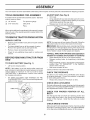 6
6
-
 7
7
-
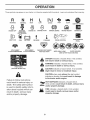 8
8
-
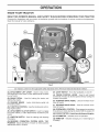 9
9
-
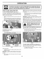 10
10
-
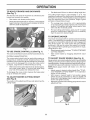 11
11
-
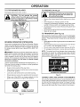 12
12
-
 13
13
-
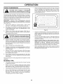 14
14
-
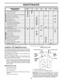 15
15
-
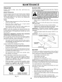 16
16
-
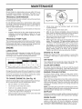 17
17
-
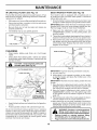 18
18
-
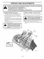 19
19
-
 20
20
-
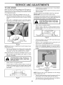 21
21
-
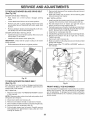 22
22
-
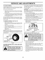 23
23
-
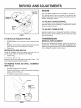 24
24
-
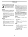 25
25
-
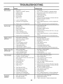 26
26
-
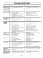 27
27
-
 28
28
-
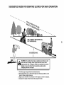 29
29
-
 30
30
-
 31
31
-
 32
32
-
 33
33
-
 34
34
-
 35
35
-
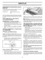 36
36
-
 37
37
-
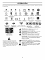 38
38
-
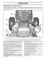 39
39
-
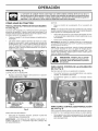 40
40
-
 41
41
-
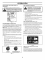 42
42
-
 43
43
-
 44
44
-
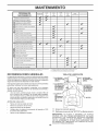 45
45
-
 46
46
-
 47
47
-
 48
48
-
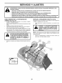 49
49
-
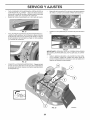 50
50
-
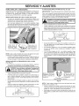 51
51
-
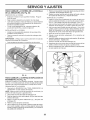 52
52
-
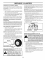 53
53
-
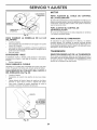 54
54
-
 55
55
-
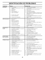 56
56
-
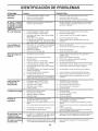 57
57
-
 58
58
-
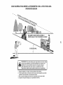 59
59
-
 60
60


Dixon D22KH46 (96046001200) El manual del propietario
- Categoría
- Tractor
- Tipo
- El manual del propietario
- Este manual también es adecuado para
