Simplicity 074026-00 Manual de usuario
- Categoría
- Compresores de aire
- Tipo
- Manual de usuario
Este manual también es adecuado para

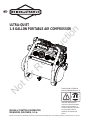
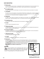
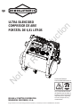
Read and understand this
instruction manual thoroughly
before using the product. It
contains important information
for your safety as well as
operating and maintenance
advice.
BRIGGS & STRATTON IS A TRADEMARK OF BRIGGS & STRATTON CORPORATION AND IS USED UNDER LICENSE TO ALTON INDUSTRY LTD. GROUP
ULTRA-QUIET
1.8 GALLON PORTABLE AIR COMPRESSOR
Product Model # 074026-00
Manual #80018809 Revision: A
BRIGGS & STRATTON CORPORATION
MILWAUKEE, WISCONSIN, U.S.A.
Not for Reproduction

BRIGGSandSTRATTON.COM
Thank you for purchasing this quality-built Briggs & Stratton ™ air compressor. We are pleased that
Briggs & Stratton brand. When operated and maintained
according to the instructions in this manual, your Briggs &Stratton air compressor will provide many
years of dependable service.
You can contact Briggs & Stratton Customer Service by phone at (800) 743-4115, or on the
Internet at BRIGGSandSTRATTON.COM.
Date Purchased
2
Not for Reproduction

80018569
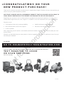
Thank you for choosing a product manufactured or supported by Briggs & Stratton. We are honored that you
chose us as your power equipment provider.
WE STRIVE TO CREATE HELPFUL, DEPENDABLE PRODUCTS THAT YOU CAN RELY ON FOR YEARS TO
COME, WHILE COUNTING ON US TO SUPPORT YOU THROUGH THE LIFE OF YOUR PRODUCT.
Registering your product is the mrst step towards receiving the best post-sale experience. To begin, go to
onlineproductregistration.com, text ‘register’ to 33988 or scan the code below from your mobile device.
Benemts include:
t Conmrmation of warranty coverage eligibility
t More efmcient parts and service support
t Product updates
t Helpful maintenance and usage tips
t Discounts and offers on future products
After registering you will receive a conmrmation email that includes an invitation to rate and review your new
product online.
Whether you absolutely love your new product or have a suggestion to enhance it, we’d love to hear from you
and value your feedback.
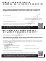
CONGRATULATIONS ON YOUR
NEW PRODUCT PURCHASE!
TO BEGIN:
GO TO ONLINEPRODUCTREGISTRATION.COM
TEXT ‘REGISTER’ TO 33988
OR SCAN THIS CODE:
Data rates may apply
OR TO START THE REGISTRATION PROCESS ON YOUR MOBILE DEVICE:
Not for Reproduction

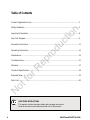
Table of Contents
Safety Guidelines..................................................................................................................
Product Registration Form....................................................................................................
Important Information...........................................................................................................
Assembly Instructions..........................................................................................................
Operating Instructions..........................................................................................................
Technical Specifications........................................................................................................
Maintenance.........................................................................................................................
Troubleshooting....................................................................................................................
Exploded View.......................................................................................................................
Parts List...............................................................................................................................
Warranty...............................................................................................................................
Key Parts Diagram.................................................................................................................
BRIGGSandSTRATTON.COM
4
SAVE THESE INSTRUCTIONS
This manual contains important safety and operating instructions.
Read all instructions and follow them with use of this product.
3
5
8
9
11
12
14
15
17
18
19
20
Not for Reproduction

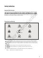
Flying Objects
Operator's Manual
Hot Surface
Electrical ShockToxic Fumes
Safety Guidelines
Important Safety Information
Safety Symbols and Meanings
The manufacturer cannot possibly anticipate every possible circumstance that might involve a hazard. The warnings
work method, or operating technique that the manufacturer does not specifically recommend, you must satisfy
yourself that it is safe for you and others. You must also make sure that the procedure, work method, or operating
technique that you choose does not render the compressor unsafe.
Warning
BurstingFire
The safety alert symbol indicates a potential hazard to personal injury. A signal word (DANGER, WARNING, or
CAUTION) is used with the alert symbol to designate a degree or level of hazard seriousness. A safety symbol may
be used to represent the type of hazard. The signal word NOTICE is used to address practices not related to personal
injury.
indicates a hazard which, if not avoided, will result in death or serious injury.
indicates a hazard which, if not avoided, could result in death or serious injury.
indicates a hazard which, if not avoided, could result in minor or moderate injury.
address practices not related to personal injury.
DANGER
WARNING
CAUTION
Notice
5
Explosion
Not for Reproduction

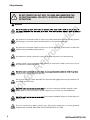
DO NOT OPERATE THIS UNIT UNTIL YOU READ AND UNDERSTAND THIS
INSTRUCTION MANUAL FOR SAFETY, OPERATION, AND MAINTENANCE
INSTRUCTIONS.
compressor.
.
Do not restrict compressor ventilation openings or place
objects against or on top of compressor. Operate compressor only in a clean, dry, well ventilated area.
High pressure air could result in death or serious injury. Never operate above maximum operating pressure
of the spray gun or tool. Drain water from tank after each use. Do not weld or repair tank.
or ignition sources including the compressor unit.
High pressure air could result in death or serious injury. Do not operate with pressure switch or safety valve
set above maximum allowable working pressure.
Hot compressors surfaces could result in serious injury. Allow compressor to cool before touching.
Inhalation hazard. Using compressor to supply breathing air could result in death or serious injury. Do not
use compressor to supply breathing air.
Risk of serious eye injury. Always wear ANSI Z87.1 approved safety goggles when using air compressor. Do
not spray any part of the body.
Safety Information
6
WARNING
.
Do not operate unattended. Always turn off and unplug unit
when not in use.
Shock risk could result in death or serious injury. Only connect compressor to a properly grounded
receptacle. KEEP CHILDREN AWAY FROM THE AIR COMPRESSOR AT ALL TIMES.
BRIGGSandSTRATTON.COM
Not for Reproduction

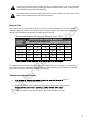
As the distance from the supply outlet increases, you must use a heavier gauge extension cord. Using extension
cords with inadequately sized wire causes a serious drop in voltage, resulting in loss of power and possible product
damage. Refer to the table here to determine the required minimum wire size.
Extension Cords
The smaller the gauge number of the wire, the greater the capacity of the cord. For example, a 14 gauge cord can
carry a higher current than a 16 gauge cord. When using more than one extension cord to make up the total length,
be sure each cord contains at least the minimum wire size required.
Guidelines for using extension cords
-A"("W" in
Canada) to indicate it is acceptable outdoor use.
Ensure your extension cord is properly wired and in good electrical condition. Always replace a
Protect your extension cords from sharp objects, excess heat, and damp or wet areas.
Recommended Minimum Wire Gauge for Extension Cords* (120 V)
0 - 5
5.1 - 8
8.1 - 12
12.1 - 15
15.1 - 20
16
16
14
12
10
16
16
14
12
10
16
16
14
12
10
14
12
10
10
-
12
10
-
-
-
12
-
-
-
-
CORD SIZE IN AWG (AMERICAN WIRE GAUGE)
Extension cord length in feet
*
AMPERE
RATING
25' 50' 75' 100' 150' 200'
Dust can be created when cutting, sanding, drilling or grinding materials such as wood, paint, metal,
concrete, cement, or other masonry. To reduce your exposure to these chemicals, work in a well ventilated
area and ALWAYS wear approved safety equipment.
This product contains chemicals, including lead, know to the state of California to cause cancer and birth
defects or other reproductive harm. Wash hands after handling.
7
Not for Reproduction

BRIGGSandSTRATTON.COM
8
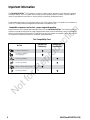
This BRIGGS&STRATTON ™ Air Compressor is ideal for a wide range of applications from fastening to greasing
and engine cleaning. The 1.8 U.S.gallon (6.81L) design provides optimum pressure. It features a 3/4 HP induction
motor for quiet operation and a cast-iron, oil-less pump for long-lasting, reliable performance.
The procedures described in this manual are solely for this 1.8 U.S.gallon (6.81L) air compressor at a maximum of
P=125 PSI. The device has been designed and constructed for household use only.
Important Information
Always ensure the use of appropriately matched air tools with your BRIGGS&STRATTON ™Air Compressor. Be sure
that the air compressor being used can supply the appropriate volume, pressure and delivery rate of air to the tool(s)
without running continuously. Using tools or combinations of tools that, together or separately, require more than the
air compressor can deliver will void the air compressor guarantee/warranty.
Compatible compressor and air tool - proper usage and operation
Tool Compatibility Chart
Air Tool
Operates Tool
Continuously
Operates Tool
Intermittently
*OnBUJPO$MFBOJOH
'JOJTIJOH/BJMFS
HBVHF
'SBNJOH/BJMFS
'MPPSJOH/BJMFS
#SBEOBJMFSHBVHF
3PPmOH/BJMFS
Not for Reproduction

9
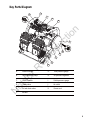
Key Parts Diagram
E. Air tank drain valve
G. Tank pressure gauge
F. Air tank
D. Safety valve
H. Air pressure regulatorB. Air compressor pump
A. Electrical motor
K. Power cord
J. Air outlet
I. Outlet pressure gaugeC. ON/OFF switch
A
B
C
D
E
F
G
H
I
J
K
K
Not for Reproduction

BRIGGSandSTRATTON.COM
10
PARTS DESCRIPTION
The motor is used to power the pump. It is equipped with a thermal overload protector. If the motor overheats for any
reason, the thermal overload protector will shut it down in order to prevent the motor from being damaged.
Electric motor
A
The pump compresses the air and discharges it into the tank via the piston that moves up and down in the cylinder.
Air compressor pump
B
C
D
E
F
G
H
The drain valve is used to remove moisture from the air tank after the compressor is shut off.
Air tank drain valve
I
K
The tank is where the compressed air is stored.
Air tank
J
This valve is used to prevent the compressor from building too much pressure. If the pressure reaches the preset
level of the motor, it will automatically pop open. You can also pull the ring on the valve to open manually.
Safety valve
This switch turns on the compressor and is operated manually.When in the ON position, it allows the compressor
to start up or shut down automatically, without warning, upon air demand.ALWAYS set this switch to OFF when
the compressor is not being used and before unplugging the compressor.
On/off switch
The regulator is used to adjust the pressure inside the line to the tool that is being used. Turn the knob clockwise to
increase the pressure and counter-clockwise to decrease the pressure.
Air pressure regulator
The gauge measures the pressure level of the air that is stored in the tank. It cannot be adjusted by the operator and
it does not indicate the pressure inside the line.
Tank pressure gauge
The gauge measures the regulated outlet pressure.
Outlet pressure gauge
The outlet is connected to a quick connect which is connecting to air hose.
Air outlet
This product is for use on a nominal 120-volt circuit and should be grounded. A cord with a grounding plug as
ILLUSTRATEDMUSTBEUSED-AKESURETHATTHEPRODUCTISCONNECTEDTOANOUTLETTHATHASTHESAMECONlGURATIONAS
the plug (see Figure 1). No adapter should be used with this Check with a licensed electrician if the grounding
instructions are not understood or there is doubt as to whether the product is
PROPERLYGROUNDED$ONOTMODIFYTHEPLUGPROVIDED)FITWILLNOTlTTHEOUTLET
have the proper outlet installed by a licensed electrician.
Power cord
Grounded
outlet
Grounding Pin
Plug
Figure 1
DANGER
Improper installation of the grounding plug will result in a risk
of electric shock. If repair or replacement of the cord or plug
is necessarZ do not connect the grounding wire to either nat blade
terminal. The grounding wire is in the green outer surface.
Not for Reproduction

11
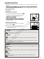
Assembly Instructions
The carton should contain:
• Unpack the air compressor unit. Inspect the unit for damaged. If the unit has been damaged, contact the retailer
immediately.
it has the required pressure rating for its intended use.
Positioning of the air compressor
1. Position the air compressor (1) near an electrical outlet (2)( ).
2. The compressor must be at least 12”(31cm) from any wall (3)
or obstruction, in a clean, well-ventilated area to ensure
).
The air compressor must be level to ensure proper drainage of
the moisture in the tank.
Connect air hose to compressor
1. Connect the air hose (1) to the compressor’s air outlet (2) with
the quick conncetor (3)( ).
Note: Air hose and quick connector are not provided, need to be
purchased separately. Apply plumber's tape on all the
threads to prevent air leakage.
1
2
3
Fig A
Notice
Hot compressor surfaces could result in serious injury. Allow compressor to cool before touching.
High pressure air could result in death or serious injury. Never operate above maximum operating
pressure of the spray gun or tool.
If the pump has been transported or turned upside down (even partially), allow the pump to sit in a normal,
upright position for approximately 10 minutes before starting.
WARNING
WARNING
• Air compressor
• Owner's manual
High pressure air could result in death or serious injury. Shut off unit, unplug and release air pressure prior
to servicing.
High pressure air containing water condensation could result in minor or moderate injury. Do not
spray at any person.
CAUTION
WARNING
WARNING
Risk of serious eye injury from moisture and debris. Always wear ANSI Z87.1 safety goggles when opening
drain valve.
12 / 31 cm
Fig B
1
2
3
Not for Reproduction

BRIGGSandSTRATTON.COM12
).
1
Fig E
4. Plug in the power cord.
Use a dedicated circuit. The compressor will use the full capacity of a typical 15A household circuit. If any
other electrical devices are drawing from the compressor's circuit, the air compressor may fail to start. Low
voltage or an overload circuit can result in sluggish starting that causes the motor overload protection system
or circuit breaker to trip, especially in cold conditions.
Disconnect the power cord only after break-in process has been completed, otherwise the motor might get
damaged.
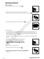
5. Set the pressure switch (1) to the ON position. The compressor will
start. Run the compressor for 30 minutes. If it fails, turn it off
immediately and call the toll-free helpline at: 1-800-743-4115.
use( ).
6. After 30 minutes, turn off the pressure switch.
7. Close the tank drain valve (1) by turning it clockwise (
).
8. Set the pressure switch to the ON position. The air receiver will fill to cut-out
pressure and then the compressor's motor will stop. The compressor is now
ready for use.
2. Open tank drain valve (1) by turning it counter-clockwise to permit the air
to escape and prevent air pressure build-up in the air tank during the break-in period (
3. Turn the air pressure regulator knob (1) clockwise
until it stops (
).
Break in the pump
1.Set the pressure switch (1) to the OFF position ( ).
Operating Instructions
1
OFF
ON
Fig D
1
Fig C
1
OFF
ON
Fig G
1
Fig F
t
t
Not for Reproduction

13
Operating Instructions
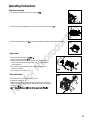
3. Attach hose and accessories ( ).(Hose and accessories need to be purchased separately.)
3. Set the pressure switch to the ON position and allow the tank
pressure to build. Motor will stop when tank pressure reaches
cut-out pressure.
4. Turn the air pressure regulator knob clockwise until desired
pressure is reached.
5. The compressor is ready for use.
1. Close the tank drain valve (1
2. Plug-in the power cord(2)( )
(
)
How to start
2
Fig K
How to shut down
1.Set the pressure switch (1) to the OFF position.
2.Unplug the power cord (2).
.
3.Reduce the pressure in the tank through the outlet hose. Pulling the
safety valve ring (3) and keeping it open will also reduce the pressure
in the tank (
the
).
2
3
1
Fig L
1. Set the pressure switch (1) to the OFF position
2. Turn the air pressure regulator knob (1) counter-clockwise until it stops
Before each start-up
( ).
( ).
1
OFF
ON
Fig J
1
Fig I
1
Fig H
Not for Reproduction

BRIGGSandSTRATTON.COM14
Check Safety Valve
Before starting the compressor, pull the ring on the safety valve to make sure that the safety valve
operates freely. If the valve is stuck or does not operate smoothly, contact a trained service technician.
How To Drain Tank
1. Set the pressure switch to the O (OFF) position.
2. Unplug the power cord.
3. Turn air pressure regulator knob counter-clockwise to set the outlet pressure to zero.
4. Pull and hold ring on safety valve, allowing air to bleed from the tank until air pressure is minimized.
5. Place suitable container under unit to catch water.
6. Slightly tilt unit and turn drain valve counter-clockwise to open.
7. After the water has been drained,close the drain valve(clockwise). The air compressor can now be stored.
How to Clean The Air Filter
Check that all connections are tight. Small leaks in the tank, hoses,connections or
transfer tubes will substantially reduce the air compressor and tool performance.
Spray a small amount of soapy water around the area of suspected leaks with a
spray bottle. If bubbles appear, repair, replace or reseal the faulty component.
Do not over-tighten any connections.
Before storing the air compressor:
• Drain tank (page 14).
• Use an air blow gun to clean all dust and debris from the compressor.
• Disconnect and wind up the power cord.
• Clean the ventilation openings on the motor enclosure with a damp cloth.
• Drain all moisture from the tank.
• Pull the pressure safety valve to release all pressure from the tank.
•
WARNING:Storage covers could cause a fire resulting in death or serious injury.
-Do not place a storage cover over a hot air compressor.
-Let equipment cool for a sufficient time before placing the cover on
the equipment.
• Store the air compressor in a clean and dry location.
• In cold weather, store the compressor in a warm building when it is not in use.
This will reduce problems related to starting the motor and the freezing of water
condensation.
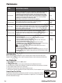
Pull the safety valve daily to ensure that it is operating properly
and to clear the valve of any possible obstructions.
DESCRIPTION / REASON
SERVICE
INTERVAL
ITEM
Through normal operation of your air compressor, condensation of water will
accumulate in the tank. To prevent corrosion of the tank from the inside,
condensation must be drained at the end of every workday. Be sure to wear
protective goggles. Relieve the air pressure in the system then open the drain
valve on the bottom of the tank to drain. Under cold conditions it is especially
important to drain the tank after each use to reduce the chance of problems
resulting from the freezing of condensation water.
NOTE: Refer to instructions on how to drain tank (page 14).
Drain the tank
Check the valve
Test for leaks
Storage
Daily
Daily
Monthly
Prior to
storing
Maintenance
#LEANTHEAIRlLTER
!DIRTYAIRlLTERWILLREDUCEAIRCOMPRESSORPERFORMANCEANDLIFE4OAVOID
CONTAMINATINGTHEPUMPTHElLTERSHOULDBECLEANEDFREQUENTLYANDREPLACEDON
a regular basis. Clean the cartridge filter by blowing on it with a blow gun
(page 14).
Weekly
A dirty filter will reduce the unit s performance and life. To avoid any contamination inside the
pump, the filter should be cleaned weekly and replaced on a regular basis. The cartridge filter
should be cleaned with blow gun.
I
Not for Reproduction

15
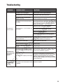
Troubleshooting
The power cord is not plugged in.
The motor’s thermal overload protection
has tripped.
POSSIBLE CAUSE
PROBLEM
The motor will
not run or start
Plug the power cord into a grounded outlet.
Set the power switch to the ON position.
The power switch is in the O (OFF)position.
The extension cord is the wrong wire
gauge or is too long.
A fuse has blown or a circuit breaker has
been tripped.
The air tank pressure exceeds the preset
pressure switch limit.
The safety valve is stuck open.
Electrical connections are lose.
The motor, capacitor or safety valve is
defective.
The motor runs
continuously when
the pressure switch
is in the ON
position.
Check extension cord information (page 7) for the
proper wire gauge and cord length.
Turn the air compressor off, unplug the power cord and
wait until the motor has cooled down. Plug in the power
cord only after the motor has cooled down, and wait wait
at least 5 minutes to make sure the thermal overload
protector has recovered.
Replace the fuse or reset the circuit breaker.
Verify that the fuse has the proper amperage.
Check for low voltage conditions.
Disconnect any other electrical appliances from the
circuit or operate the compressor on a dedicated circuit.
The motor will start automatically when the tank
pressure drops below the cut-in pressure.
Clean or replace the safety valve.
Contact an authorized service center, or call
1-800-743-4115
Contact an authorized service center, or call
1-800-743-4115
Set the pressure switch to the OFF position. If the motor
does not shut off, unplug the air compressor. If the
pressure switch is defective, replace it.
Check the air requirements of the accessory that is
being used. If it is higher than the CFM (Cubic Feet per
Minute) and pressure supplied by the compressor
(page 18), a larger capacity air compressor is needed.
Most accessories are rated at 25% of actual CFM while
running continuously.
The pressure switch does not shut off the
motor when the air compressor reaches
the cut-out pressure and the safety valve
activates.
The compressor’s capacity is not enough.
The regulator does
not regulate the
pressure.
The regulator or its internal parts are dirty
or damaged.
Replace the regulator.
SOLUTIONS
Not for Reproduction

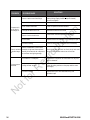
BRIGGSandSTRATTON.COM16
Prolonged excessive use of air.
POSSIBLE CAUSE
PROBLEM
The pressure is
low or there is
not enough air.
Close the drain valve.
Check the fittings with soapy water. Tighten or reseal
leaking fittings (apply plumber s tape on threads).
Do not over tighten.
Clean or replace the air filter element.
SOLUTIONS
The tank drain valve is open.
There is a leak at one of the fittings.
The air intake is restricted.
There is a hole in the air hose.
There is condensation in the air tank
caused by a high level of atmospheric
humidity or because the air compressor
has not been running long enough.
The tank leaks.
The ventilation is inadequate.
Cooling surfaces are dirty.
There is moisture
in the discharge
air.
Decrease the amount of air used.
Check the air hose and replace it if necessary.
Replace the tank immediately. Do not attempt to repair it.
Relocate the compressor to an area with cool, dry and
well-circulated air.
Clean all cooling surfaces on the pump and the motor
thoroughly.
Replace worn parts and reassemble using new
plumber's tape.
The compressor
overheats.
Check for worn parts and replace them if necessary.
Drain the air tank after each use. Drain the air tank more
often in humid weather and use an air-line filter.
The valve is leaking.
The valve is leaking.
Not for Reproduction

17
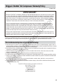
Briggs & Stratton Air Compressor Warranty Policy
This Limited warranty does not include the following:
LIMITED WARRANTY
A. Parts that are worn or broken or which have become inoperative due to abuse, misuse, accidental damage, neglect or lack of
proper installation, operation or maintenance (as outlined in the applicable owner’s manual or operating instructions) or product
that has been used for industrial, professional, commercial or rental purposes;
B. Normal wear and tear or expendable parts or accessories that may be supplied with the product which are expected to become
inoperative or unusable after a reasonable period of use;
C. Routine maintenance and consumable items such as, but not limited to fuel, lubricants, valves, belts, knobs, nuts, fluids,
tune-ups, or adjustments;
D. Damage caused by repairs made or attempted by persons not authorized by the manufacturer;
E. Product that was sold to the original purchaser as reconditioned or refurbished product (unless otherwise specified in writing);
F. Product or parts thereof if any part from another manufacturer has been installed or any repairs or alterations have been made
or attempted by unauthorized persons;
G. Normal deterioration of the exterior finish such as, but not limited to, scratches, dents, paint chips, nor any corrosion or
discoloring by heat, abrasive and chemical cleaners;
H. Component parts sold by and identified as the product of another company, which shall be covered under the other product
manufacturer’s warranty, if any.
October, 2015
These are our standard warranty terms, but occasionally there may be additional warranty coverage that was not determined at
time of publication. For a listing of current warranty terms for your air compressor, go to BRIGGSandSTRATTON.COM
BRIGGS & STRATTON is a trademark of BRIGGS & STRATTON CORPORATION and is used under license to Alton Industry
Co. Ltd®. Alton Industry Co. Ltd warrants this Briggs & Stratton brand product for a period of one year from the date of
original retail purchase against defects in materials and workmanship. Subject to the conditions and limitations described
below, if Alton Industry Co. Ltd determines this product is covered under this warranty, it will be replaced with the same
model or one of equal value or specification, at Alton Industry Co. Ltd’s option. Alton Industry Co. Ltd will bear the cost of
replacement. The purchaser must contact Alton Industry Co. Ltd® for all warranty authorizations.
There is no other express warranty. Implied warranties, including those of merchantability and fitness for a particular
purpose, are limited to one year, or to the extent permitted by law. Liability for incidental or consequential damages are
excluded to the extent exclusion is permitted by law. Some states or countries do not allow limitations on how long an
implied warrant lasts, and some states of countries do not allow the exclusion or limitation of incidental or consequential
damages, so the above limitation and exclusion may not apply to you. This warranty gives you specific legal rights and you
may also have other rights which vary from state to state or country to country.
Save your proof of purchase receipt. If you do not provide proof of the initial purchase date at the time warranty service is
requested, the manufacturing date of the product will be used to determine the warranty period. Product registration is not
required to obtain warranty service on Briggs & Stratton products.
TM
TM
For questions about our warranty on this product, contact us at:
Alton Industry LTD. Group
1031 North Raddant Road
Batavia Illinois 60510
888-899-0146
www.altonindustries.com
Not for Reproduction

BRIGGSandSTRATTON.COM18
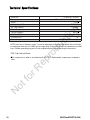
*CFM: Cubic Feet per Minute.
This compressor is rated in accordance with ISO 1217, displacement compressors acceptance
tests.
Model No.
Pump
Motor
Voltage/Amps/HZ
Cut-in Pressure
Air Tank Capacity
Cut-out Pressure
CFM @ 40 PSI
CFM @ 90 PSI
Power Cord
Oil free, Direct drive, Single stage
074026-00 / 3301841
3/4 HP
120/5.7/60
1.8 Gallon
95 PSI
125 PSI
2.4
1.8
SJT 18 AWG / 72 in. Length
*
*
NOTE: Avoid use of extension cords. If use of an extension cord cannot be avoided, the cord should
be a minimum wire size of 14 AWG and no longer than 30 feet. Use only a 3-wire extension cord that
has a 3-blade grounding plug and a 3-slot receptacle that will accept the plug on the product.
Not for Reproduction

19
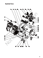
Exploded View
Not for Reproduction

BRIGGSandSTRATTON.COM20
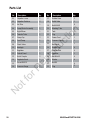
Parts List
Capacitor cover
Capacitor Retainer
Air Filter
Pump/Motor Assembly
Transfer Tube
Quick Coupler
Check Valve
Cord Clamp
Right Elbow
Handgrip
Regulator
Control Panel
Crimp Cup
Screw M4X10 Nut M6
Regulator Knob
Bleeding Tube
Relief Valve
Tank
Plug
Ball Valve
Rubber Foot
Bolt M6×12
Cushion Pad
Capacitor
Washer
Pressure Switch
Power Cord
17
18
19
20
21
22
23
24
25
26
27
28
29
30
Rubber Hose
Bolt M6×12
01
02
03
04
05
06
07
08
09
10
11
12
13
14
15 31
1
2
1
1
1
1
2
1
1
1
1
1
2
1
Pressure Gauge
16
2
Plug
32
2
3
1
1
8
1
1
2
1
1
1
4
4
1
4
4
4
Description Qty.No.
Description
Qty.No.
Not for Reproduction

Lea y comprenda este manual
del operador antes de utilizar el
producto. Contiene información
importante para su seguridad,
así como consejos de uso y
mantenimiento.
Briggs & Stratton es una marca de Briggs & Stratton Corparation y se utilizan bajo licencia a ALTON INDUSTRY LTD.GROUP
ULTRA SILENCIOSO
COMPRESOR DE AIRE
PORTÁTIL DE 6,81 LITROS
Producto # 074026-00
Manual # 80018809 Revisión: A
BRIGGS & STRATTON CORPORATION
MILWAUKEE, WISCONSIN, U.S.A.
Not for Reproduction

BRIGGSandSTRATTON.COM
2
Donde estamos
TM
Not for Reproduction

80018569
Gracias por elegir un producto fabricado o respaldado por Briggs & Stratton. Estamos honrados de que nos escoja
como su proveedor de equipos de energía.
NOS ESFORZAMOS POR CREAR PRODUCTOS DE UTILIDAD Y CONFIABLES EN LOS CUALES PUEDA
DEPENDER DURANTE MUCHOS AÑOS, AL MISMO TIEMPO DE PODER SEGUIR APOYÁNDOLO A LO
LARGO DE LA VIDA ÚTIL DE SU PRODUCTO.
Registrar su producto es el primer paso hacia recibir la mejor experiencia post-venta. Para comenzar, visite
onlineproductregistration.com, texto ‘register’ para 33988 o escanee el código a continuación de su dispositivo móvil.
Los benemcios incluyen:
t Conmrmación de garantía de elegibilidad
de cobertura
t Partes más emcientes y apoyo de servicio
t Actualizaciones de productos
t Mantenimiento útiles y consejos sobre utilización
t Descuentos y ofertas sobre futuros productos
Después del registro usted recibirá un correo electrónico de conmrmación que incluye una invitación para calimcar y
comentar su nuevo producto en línea.
Nos encantaría saber de usted y valoramos sus comentarios, independientemente de que le
encante su nuevo producto o tenga sugerencias para mejorarlo.
PARA COMENZAR, VISITE ONLINEPRODUCTREGISTRATION.COM,
TEXTO ‘REGISTER’ PARA 33988 O ESCANEE ESTE CÓDIGO
para comenzar con el proceso de registro en su dispositivo móvil. Aplica tarifas de datos.
¡FELICITACIONES POR LA
COMPRA DE SU NUEVO PRODUCTO!
Merci d’avoir choisi un produit fabriqué ou soutenu par Briggs & Stratton. C’est pour nous un honneur que vous nous
ayez choisis à titre de fournisseur d’équipement électrique.
NOUS NOUS EFFORÇONS DE CRÉER DES PRODUITS UTILES ET FIABLES SUR LESQUELS VOUS POUVEZ
COMPTER DURANT PLUSIEURS ANNÉES, TOUT EN POUVANT COMPTER SUR NOUS POUR VOUS OFFRIR DU
SOUTIEN DURANT TOUTE LA DURÉE DE VIE DE VOTRE PRODUIT.
L’enregistrement de votre produit est la première étape à suivre en vue de promter d’une excellente expérience après-
vente. Pour commencer, visitez le onlineproductregistration.com, texte ‘register’ pour 33988 ou balayez le code ci-
dessous avec votre appareil mobile.
t Conmrmation de l’admissibilité à la couverture
de la garantie
t Soutien plus efmcace en matière de pièces
et de service
t Mises à jour sur les produits
t Conseils utiles sur l’entretien et l’utilisation
t Rabais et offres sur les futurs produits
Après vous être enregistré, vous recevrez un courriel de conmrmation incluant une invitation
à coter et à commenter votre nouveau produit en ligne.
Que vous adoriez votre nouveau produit ou que vous ayez une suggestion en vue de l’améliorer,
nous serions heureux de recevoir de vos nouvelles, car vos commentaires nous importent.
POUR COMMENCER, VISITEZ LE ONLINEPRODUCTREGISTRATION.COM,
TEXTE ‘REGISTER’ POUR 33988 OU BALAYEZ CE CODE pour lancer le processus
d’enregistrement sur votre appareil mobile. Des frais de données s’appliquent.
FÉLICITATIONS POUR L’ACHAT
DE VOTRE NOUVEAU PRODUIT!
Not for Reproduction

Índice
DIRECTRICES DE SEGURIDAD.............................................................................................
FORMULARIO DE REGISTRO DEL PRODUCTO....................................................................
INFORMACIÓN IMPORTANTE...............................................................................................
INSTRUCCIONES DE ENSAMBLAJE.....................................................................................
INSTRUCCIONES DE FUNCIONAMIENTO.............................................................................
ESPECIFICACIONES TÉCNICAS............................................................................................
MANTENIMIENTO.................................................................................................................
CUIDADO Y MANTENIMIENTO....................................................................................................
VISTA DETALLADA..............................................................................................................
LISTA DA PIEZAS................................................................................................................
GARANTÍA............................................................................................................................
CLAVE DIAGRAMA DE PIEZAS..............................................................................................
BRIGGSandSTRATTON.COM
4
GUARDE ESTAS INSTRUCCIONES
Este manual contiene instrucciones importantes de seguridad y funcionamiento.
Lea todas las instrucciones y seguirlas con el uso de este producto.
3
5
8
9
11
12
14
15
17
18
19
20
Not for Reproduction

5
El vuelo se opone
Manual del operador
Superficie caliente
Choque eléctricoVapores toxicos
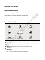
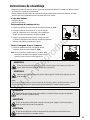
Directrices de seguridad
Información importante de seguridad
Símbolos de seguridad y significados
El fabricante no puede anticipar todas las posibles circunstancias que puedan implicar un riesgo. Las advertencias
de este manual y las etiquetas y calcomanías adheridas a la unidad, por lo tanto, no todos los servicios incluidos.
Si utiliza un procedimiento, método de trabajo o técnica de operación que el fabricante no recomienda específicamente,
debe satisfacer a ti mismo de que es seguro para usted y los demás. También debe asegurarse de que el procedimiento,
método de trabajo o técnica de operación que elija no haga al compresor inseguro.
Advertencia
Muy llenoFuego
El símbolo de alerta de seguridad indica un riesgo potencial de lesiones personales. Una palabra (PELIGRO,
ADVERTENCIA o PRECAUCIÓN) se utiliza con el símbolo de alerta para designar un grado o nivel de gravedad del
riesgo. Un símbolo de seguridad puede ser usado para representar el tipo de peligro. La palabra de señalización
AVISO \ s utilizado para prácticas de dirección no relacionados con lesiones personales.
indica un peligro que, si no se evita, provocará la muerte o lesiones graves.
indica un peligro que, si no se evita, podría causar la muerte o lesiones graves.
indica un peligro que, si no se evita, podría causar lesiones leves o moderadas.
prácticas de dirección no relacionados con lesiones personales.
PELIGRO
ADVERTENCIA
PRECAUCIÓN
aviso
Explosión
Not for Reproduction

Riesgo de incendio podría causar la muerte o lesiones graves. No restrinja los orificios de ventilación del
compresor o colocar objetos en contra o en la parte superior del compresor. Opere el compresor sólo en
un área limpia, seca y bien ventilada.
De aire de alta presión podría causar la muerte o lesiones graves. No opere con interruptor de presión o
válvula de seguridad establecido por encima de la presión máxima de trabajo permitida.
Superficies compresores calientes podrían causar lesiones graves. Permita que el compresor se enfríe
antes de tocarlo.
Peligro de inhalación. El uso del compresor para suministrar aire respirable puede causar la muerte o
lesiones graves. No hay compresor de uso para suministrar aire respirable.
Riesgo de incendio podría causar la muerte o lesiones graves.
No rocíe materiales inflamables en las
proximidades de nada con fuego o de ignición, incluyendo el compresor.
Riesgo de lesiones oculares graves. Siempre use ANSI Z87.1 gafas de protección cuando se utiliza el
compresor de aire. No rocíe cualquier parte del cuerpo.
Directrices de seguridad
6
ADVERTENCIA
Riesgo de incendio podría causar la muerte o lesiones graves. No ponga en funcionamiento sin vigilancia.
Siempre apague y desenchufe la unidad cuando no esté en uso.
Riesgo de choque podría causar la muerte o lesiones graves. Sólo conecte el compresor a un
receptáculo de tierra. MANTENGA A LOS NIÑOS LEJOS DEL COMPRESOR DE AIRE EN TODO
MOMENTO.
BRIGGSandSTRATTON.COM
Riesgo de incendio causado por chispas del motor y el interruptor de presión podría ocasionar la muerte o
lesiones graves. No haga funcionar el compresor cerca de gas o vapor inflamable. Nunca almacene líquidos
o gases inflamables en * proximidades de compresor.
No opere esta unidad hasta que haya leído y entendido este MANUAL DE
INSTRUCCIONES PARA LAS INSTRUCCIONES DE SEGURIDAD, operación y
mantenimiento.
De aire de alta presión podría causar la muerte o lesiones graves. Nunca opere por encima de la presión
máxima de funcionamiento de la pistola o herramienta. Drene el agua del tanque después de cada uso.
No soldar o tanque reparación.
Not for Reproduction

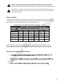
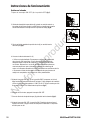
A medida que la distancia entre la toma de alimentación, se debe utilizar un cable de extensión de calibre más pesado.
El uso de extensiones inadecuadas puede causar serias caídas en el voltaje, resultando en pérdida de potencia y posible
daño al producto. Consulte la tabla para determinar el tamaño mínimo del cable.
Cables de extensión
Cuanto menor sea el número de calibre del alambre, mayor será la capacidad del cable. Por ejemplo, un cable
calibre 14 puede transportar una corriente mayor que un cable calibre 16. Cuando se utiliza más de un cable de
extensión para lograr la longitud total, asegúrese que cada acorde contiene al menos el calibre mínimo requerido.
* Basado en limitar la caída de tensión de línea a cinco voltios a 150% de los amperios nominales.
Directrices para el uso de cables de extensión
en Canadá) para indicar que es el uso en exteriores aceptable.
Alway reemplazar un cable de extensión dañada o hágala reparar por un técnico cualificado antes de
utilizarlo.
Calibre mínimo recomendado para cables de extensión * (120V)
0 - 5
5.1 - 8
8.1 - 12
12.1 - 15
15.1 - 20
16
16
14
12
10
16
16
14
12
10
16
16
14
12
10
14
12
10
10
-
12
10
-
-
-
12
-
-
-
-
CABLE DE TAMAÑO EN AWG (American Wire Gauge)
Longitud del cable de extensión en pies
AMPERE
RA
TING
25' 50' 75' 100' 150' 200'
Cuando corta lija, taladra o pule materiales como por ejemplo madera, pintura, metal, hormigón,
cemento, u otro tipo de mampostería se puede producir polvo. Para reducir la exposición a estas
sustancias químicas, trabaje en un área bien ventilada y use siempre el equipo de seguridad aprobado.
Este producto contiene plomo y componentes de plomo que, según el Estado de California, provocan
malformaciones congénitas y ostros danos en el sistema reproductivo. Lávese las manos después de
manipular este producto.
7
Not for Reproduction

BRIGGSandSTRATTON.COM
8
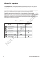
Esta BRIGGS&STRATTON ™ Compresor de aire es ideal para una amplia gama de aplicaciones, desde la fijación de
engrase y limpieza del motor. El 1.8 USgallon (6.81L) diseño proporciona una presión óptima. Cuenta con un motor
de inducción HP 3/4 para un funcionamiento silencioso y una fundición, bomba sin aceite para un rendimiento
duradero y fiable.
Los procedimientos descritos en este manual son únicamente para este compresor de aire 1.8 USgallon (6.81L) en un
máximo de P = 125 PSI. El dispositivo ha sido diseñado y construido para uso doméstico solamente.
Información importante
Asegúrese siempre de que el uso de las herramientas de aire apropiadamente emparejados con su BRIGGS&STRATTON ™
Compresor de aire. Asegúrese de que el compresor de aire que se utiliza puede suministrar el tipo de volumen, la
presión y la entrega adecuada de aire a la herramienta (s) sin correr continuamente. El uso de herramientas o
combinaciones de herramientas que, juntos o por separado, requieren más que el compresor de aire puede ofrecer, se
anulará la garantía del compresor de aire / garantía.
Compatible compresor y herramientas de aire - el uso adecuado y el funcionamiento
Tabla de compatibilidad de herramientas
Air Tool
Operates Tool
Continuously
Operates Tool
Intermittently
*OnBUJPO$MFBOJOH
'JOJTIJOH/BJMFS
HBVHF
'SBNJOH/BJMFS
'MPPSJOH/BJMFS
#SBEOBJMFSHBVHF
3PPmOH/BJMFS
Not for Reproduction

9
Clave diagrama de piezas
E. Válvula de bolaABRIR del tanque de aire
G. Indicador de presión del tanque
F. Tanque de aire
D. Válvula de bola de presión
H. Regulador de presión de aireB. Bomba del compresor de aire
A. Motor eléctrico
K. Cable de alimentación
J. Salida de la línea de aire
I. Indicador de presión reguladoC. Interruptor de ENCENDIDO/APAGADO
A
B
C
D
E
F
G
H
I
J
K
K
Not for Reproduction

BRIGGSandSTRATTON.COM
10
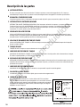
Descripción de las partes
El motor se usa para hacer funcionar la bomba. Contiene un protector contra sobrecargas térmicas. Si el motor se
sobrecalienta por cualquier razón, el protector contra sobrecargas térmicas lo apagará a fin de evitar que sufa daños.
MOTOR ELÉCTRICO:
A
La bomba comprime el aire y lo descarga en el tanque a través del pistón que se mueve arriba y abajo en el cilindro.
BOMBA DEL COMPRESOR DE AIRE
B
C
D
E
F
G
H
VÁLVULA DE DRENAJE DEL TANQUE: La válvula de drenaje sa usa para eliminar la humedad del tanque de aire después
de que la unidad se apaga.
VÁLVULA DE BOLAABRIR DEL TANQUE DE AIRE
I
K
TANQUE DE AIRE: El tanque se usa para almacenar el aire comprimido.
TANQUE DE AIRE
J
VÁLVULA DE DESCARGA DE PRESIÓN: La válvula se usa para prevenir fallas en el sistema al liberar la presión que se
acumula en este. Si la presión llega al nivel predeterminado y el interruptor de presión no apaga el motor, esta se abrirá
automáticamente. También puede jalar el anillo en la válvula para abrirla.
VÁLVULA DE BOLA DE PRESIÓN
INTERRUPTOR ON/OFF (ENCENDIDO/APAGADO): Este interruptor enciende el compresor y se opera manualmente.
Cuando está en la posición de ENCENDIDO, permite que el compressor arranque o se detenga automáticamente,
sin aviso, según la demanda de aire. SIEMPRE coloque este interruptor en la posición de APAGADO cuando el
compressor no se esté usando y antes de desenchufarlo.
INTERRUPTOR DE ENCENDIDO/APAGADO
REGULADOR DE PRESIÓN DE AIRE: El regulador se usa para regular la línea de presión a la herramienta que va a usar. Gire
la perilla en dirección de las manecillas del reloj para aumentar la presión y en dirección contraria a las manecillas del reloj
para disminuir la presión.
REGULADOR DE PRESIÓN DE AIRE
INDICADOR DE PRESIÓN DEL TANQUE: El indicador se usa para medir el nivel de presión de aire almacenada en el tanque.
El usuario no puede ajustarlo y no indica la presión de línea.
INDICADOR DE PRESIÓN DEL TANQUE
INDICADOR DE PRESIÓN REGULADO: El indicador se usa para medir la presión de salida regulada.
INDICADOR DE PRESIÓN REGULADO
La salida está conectada a una conexión rápida, que se conecta a la manguera de aire.
SALIDA DE LA LÍNEA DE AIRE
Este compresor debe utilizarse en un circuito de tierra de 120 V nominales.
Utilice un cable de alimentación que está equipado con un enchufe de conexión
a tierra. Verifique que el compresor esté enchufado a una toma de corriente que
tenga la misma configuración que el enchufe (comsulte la Figura). No haga un
adaptador con este compresor.
CABLE DE ALIMENTACIÓN
Not for Reproduction

11
Instrucciones de ensamblaje
La caja debe contener:
s$ESEMBALELAUNIDADDECOMPRESORDEAIRE)NSPECCIONELAUNIDADPARADAÅADA3ILAUNIDADSEHADAÅADOPÆNGASE
ENCONTACTOCONELVENDEDORINMEDIATAMENTE
s2EVISELAETIQUETADEIDENTIFICACIÆNDELCOMPRESORDEAIREPARAASEGURARSEDEQUEUSTEDHACOMPRADOELMODELO
PREVISTOYQUETIENELACAPACIDADDEPRESIÆNREQUERIDAPARASUUSOPREVISTO
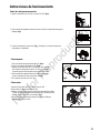
Posicionamiento del compresor de aire
1#OLOQUEELCOMPRESORDEAIRE(1CERCADEUNATOMADECORRIENTE(2(fig A)
%LCOMPRESORDEBESERDEALMENOSÑCMDECUALQUIER
PARED3UOBSTRUCCIÆNENUN·REALIMPIAYBIENVENTILADAPARA
ASEGURARELFLUJODEAIRESUFICIENTEYREFRIGERACIÆNfig A
#OLOQUEELCOMPRESORDEAIREENELSUELOOUNASUPERFICIEDURA
YNIVELADAELCOMPRESORDEAIREDEBEESTARNIVELADAPARAGARANTIZAR
ELDRENAJEADECUADODELAHUMEDADENELTANQUE
Conecte la manguera de aire al compresor
#ONECTARLAMANGUERADEAIRE1ALASALIDADEAIREDEL
COMPRESOR2CONELCONECTORR·PIDO3fig B
Nota:.OSEPROPORCIONANMANGUERADEAIREYCONECTORR·PIDO
TIENENQUESERSEADQUIEREPORSEPARADO!PLIQUECINTADE
PLOMEROENTODOELHILOSPARAEVITARFUGASDEAIRE
Aviso
3UPERFICIESCOMPRESORCALIENTEPODRÁAPROVOCARLESIONESGRAVES0ERMITAQUEELCOMPRESORSEENFRÁE
ANTESDETOCARLO
$EAIREDEALTAPRESIÆNPODRÁACAUSARLAMUERTEOLESIONESGRAVES.UNCAOPEREPORENCIMADELA
PRESIÆNM·XIMADEFUNCIONAMIENTODELAPISTOLAOHERRAMIENTA
Si la bomba se ha transportado o al revés (aunque sea parcialmente), permitir que la bomba que se siente en
una posición normal, en posición vertical durante aproximadamente 10 minutos antes de comenzar.
ADVERTENCIA
ADVERTENCIA
s#OMPRESORDEAIRE
s-ANUALDELPROPIETARIO
$EAIREDEALTAPRESIÆNPODRÁACAUSARLAMUERTEOLESIONESGRAVES!PAGUELAUNIDADDESENCHUFEY
LIBERARLAPRESIÆNDELAIREANTESDELAREPARACIÆN
$EAIREDEALTAPRESIÆNQUECONTIENELACONDENSACIÆNDEAGUAPODRÁAPROVOCARLESIONESLEVESO
MODERADAS.OPULVERIZARENCUALQUIERPERSONA
ADVERTENCIA
ADVERTENCIA
ADVERTENCIA
2IESGODELESIONESOCULARESGRAVESDELAHUMEDADYLASUCIEDAD3IEMPREUSEGAFASDESEGURIDAD
!.3):81ALABRIRLAV·LVULADEDRENAJE
1
2
3
Fig A
12 / 31 cm
Fig B
1
2
3
Not for Reproduction

BRIGGSandSTRATTON.COM12
4. Conecte el cable de alimentación (1)
s5TILICEUNCIRCUITODEDICADO%LCOMPRESORSEUTILICETODALACAPACIDAD
DEUNCIRCUITO!HOGARTÁPICO3IOTROSDISPOSITIVOSEL½CTRICOSEST·N
DIBUJANDODESDEELCIRCUITODELCOMPRESORELCOMPRESORDEAIREPUEDE
NOINICIARSE"AJATENSIÆNOUNCIRCUITODESOBRECARGAPUEDENPONERSEEN
MARCHALENTAQUEHACEQUEELSISTEMADEPROTECCIÆNDESOBRECARGADEL
MOTOROELINTERRUPTORAUTOM·TICODEVIAJEESPECIALMENTEENCONDICIONESDEFRÁO
s$ESCONECTEELCABLEDEALIMENTACIÆNSÆLODESPU½SDEQUEELPROCESODE
RODAJESEHACOMPLETADODELOCONTRARIOELMOTORPUEDEDAÅARSE.
!JUSTEELINTERRUPTOR/./&&1ENLAPOSICIÆN/.%LCOMPRESORSEINICIAR·
(AGAFUNCIONARELCOMPRESORDURANTEMINUTOS3IFALLAAP·GUELODEINMEDIATO
YLLAMEALALÁNEADEAYUDAGRATUITAAL4ENGAENCUENTAQUESÆLO
ESNECESARIOROMPERENLAUNIDADANTESDEPUÅOUSOfig F)
$ESPU½SDEMINUTOSAPAGUEELINTERRUPTOR/./&&
#IERRELAV·LVULADEDRENAJEDELTANQUE1GIR·NDOLOHACIALADERECHAfig G).
!JUSTEELINTERRUPTOR/./&&ALAPOSICIÆN/.%LDEPÆSITODEAIRESELLENAR·
TIPRESIÆNÑDECORTEÑYLUEGOELMOTORDELCOMPRESORSEDETENDR·%LCOMPRESOR
EST·LISTOPARASUUSO
2. 6·LVULADEDRENAJEDELTANQUEABIERTO1GIRANDOENSENTIDOCONTRARIOA
LASAGUJASDELRELOJPARAPERMITIRLASALIDADELAIREEIMPEDIRQUELAPRESIÆN
DEAIREACUMULADOENELTANQUEDURANTEELPERÁODODERODAJEfig D).
'IRELAPERILLADELREGULADORDEPRESIÆNDEAIRE1ENSENTIDOHORARIO
HASTAELTOPEfig E).
Quiebre en la bomba
.!JUSte el inteRRUPTOR/./&& (1) a la PoSICión /&& (fig C).
Instrucciones de funcionamiento
1
CERRAR
ABRIR
Fig G
CERRAR
ABRIR
1
Fig D
1
Fig E
1
Fig C
1
Fig F
Not for Reproduction

13
Instrucciones de funcionamiento
3. Conecte la manguera y accesorios (fig J). (Manguera y accesorios deben ser
comprados por separado).
3. Ajuste el interruptor ON / OFF en la posición ON y permita
que la presión del tanque construir. El motor se detendrá
cuando la presión del tanque alcanza la presión de corte.
4. Gire la perilla del regulador de presión de aire en sentido
horario hasta que se alcanza la presión deseada.
5. El compresor está listo para su uso.
1. Cierre la válvula de drenaje del tanque (1) (fig K).
2. Plug-in del cable de alimentación (2) (fig K).
Cómo empezar
Cómo cerrar
1.Ajuste el interruptor ON / OFF (1) a la posición OFF.
2.Desconecte el cable de alimentación (2).
3.Reducir la presión en el tanque a través de la manguera de salida.
Tirando del anillo de la válvula de seguridad (3) y mantenerlo abrir
también reducirá la presión en el tanque (fig L).
4.Ajuste la válvula de drenaje del tanque (1) (fig K) en ON para
garantizar el tanque se vacía.
1. Ajuste el interruptor ON / OFF (1) a la posición OFF (fig H).
2. Gire la perilla del regulador de presión de aire (1) hacia la izquierda hasta que se
detenga (fig I).
Antes de cada puesta en marcha
Fig J
CERRAR
ABRIR
2
Fig K
1
1
Fig I
1
Fig H
2
3
1
Fig L
Not for Reproduction

BRIGGSandSTRATTON.COM14
Compruebe la válvula de seguridad
Antes de arrancar el compresor, tire del anillo de la válvula de seguridad para asegurarse de que la
válvula de seguridad opera libremente. Si la válvula está atascada o no funciona sin problemas,
póngase en contacto con un técnico cualificado.
Cómo drenar el tanque
1. Ajuste el interruptor ON / OFF a la posición O (OFF).
2. Desconecte el cable de alimentación.
3. Gire la perilla del regulador de presión de aire hacia la izquierda para ajustar la presión de salida a cero.
4. Tire y mantenga anillo en la válvula de seguridad, dejando purgar el aire del tanque hasta que se reduzca
al mínimo la presión del aire.
5. Coloque un recipiente adecuado debajo de la unidad para recoger el agua.
6. Incline ligeramente la unidad y gire la válvula de drenaje hacia la izquierda para abrir.
7. Después de que el agua ha sido drenada, cierre la válvula de drenaje (sentido horario). El compresor de
aire ahora se puede almacenar.
Cómo limpiar el filtro de aire
Compruebe que todas las conexiones estén apretadas. Las pequeñas fugas en el
tanque, mangueras, conexiones o tubos de transferencia se reducirá
sustancialmente el compresor de aire y rendimiento de la herramienta. Rocíe una
pequeña cantidad de agua jabonosa alrededor de la zona de presuntos fugas con
una botella de spray. Si aparecen burbujas, reparará, reemplazará o resellar el
componente defectuoso. No apriete demasiado las conexiones.
Antes de almacenar el compresor de aire:
• Tanque de drenaje (página 14).
• Utilice una pistola de soplado de aire para limpiar todo el polvo y los escombros
del compresor.
• Desconecte y cerrar el cable de alimentación.
• Limpie las aberturas de ventilación de la carcasa del motor con un paño húmedo.
• Drene toda la humedad del tanque.
• Tire de la válvula de seguridad de presión para liberar toda la presión del tanque.
•
ADVERTENCIA: Las cubiertas para almacenamiento pueden causar un incendio con
resultado de muerte o lesiones graves.
-No Coloque una cubierta encima de un compresor de aire caliente.
-Deje el equipo fresco durante un tiempo suficiente antes de colocar la
cubierta del equipo.
• Almacene el compresor de aire en un lugar limpio y seco.
• En climas fríos, almacene el compresor en un edificio caliente cuando no está
en uso. Esto reducirá los problemas relacionados con el arranque del motor y la
congelación de agua condensación.
.
Tire de la válvula de seguridad de todos los días para asegurarse de que funciona
correctamente y para borrar el valor de las posibles obstrucciones.
DESCRIPCIÓN / RAZÓN
SERVICIO
INTERVALO
ÍTEM
A través de la operación normal de su compresor de aire, la condensación de
agua se acumulará en el tanque. Para evitar la corrosión del tanque desde el
interior, la condensación debe ser drenada al final de cada jornada de trabajo.
Asegúrese de usar gafas protectoras. Aliviar la presión de aire en el sistema a
continuación, abra la válvula de drenaje en la parte inferior del tanque para
drenar. En condiciones de frío es especialmente importante para drenar el
tanque después de cada uso para reducir el riesgo de problemas derivados de la
congelación del agua de condensación.
NOTA: Consulte las instrucciones para drenar el tanque (página 14).
Vaciar el tanque
Compruebe la
válvula
Prueba para
detectar fugas
Almacenamiento
A diario
A diario
Mensual
Antes de
almacenar
Mantenimiento
Limpie el filtro
de aire
Un filtro de aire sucio reduce el rendimiento del compresor de aire y la vida.
Evitar la contaminación de la bomba, el filtro debe limpiarse con frecuencia y
reemplazado en una base regular. Limpie el filtro de cartucho soplando en él con
una pistola de aire comprimido (página 14).
Cada semana
Un filtro sucio reducirá el rendimiento y la vida de la unidad. Para evitar cualquier tipo de
contaminación dentro de la bomba, el filtro debe limpiarse semanalmente y se sustituye sobre
una base regular. El filtro de cartucho deben limpiarse con escopeta de aire comprimido.
I
Not for Reproduction

15
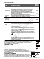
Cuidado y mantenimiento
El cable de alimentación no está enchufado.
La protección de sobrecarga térmica del
motor se ha disparado.
CAUSA POSIBLE
PROBLEMA
El motor no
funciona o iniciar
Conecte el cable de alimentación a una toma de tierra.
Ajuste el interruptor de encendido en la posición ON.
El interruptor de encendido está en la
posición ON (OFF).
El cable de extensión es el calibre del cable
equivocado o es demasiado largo.
Un fusible se ha fundido o un disyuntor
se ha disparado.
La presión del tanque excede el límite del
interruptor de presión preestablecido.
La válvula de seguridad se ha quedado
atascado abierta.
Las conexiones eléctricas están sueltas.
La válvula del motor, el condensador o la
seguridad es defectuoso.
Las carreras de
motor
Compruebe la información cable de extensión (página 7)
para el calibre del cable y el cable de longitud adecuada.
Encienda el compresor de aire, desenchufe el cable de
alimentación y espere hasta que el motor se haya
enfriado. Conecte el cable de alimentación sólo después
de que el motor se haya enfriado, y esperar esperar al
menos 5 minutos para asegurarse de que la sobrecarga
térmica protector se ha recuperado.
Reemplace el fusible o reinicie el disyuntor.
Verifique que el fusible del amperaje correcto.
Compruebe si hay condiciones de baja tensión.
Desconecte todos los demás aparatos eléctricos del
circuito u opere el compresor en un circuito dedicado.
El motor arrancará automáticamente cuando la presión
del tanque caiga por debajo de la presión de conexión.
Limpie o reemplace la válvula de seguridad.
Póngase en contacto con un centro de servicio
autorizado, o llame al 1-800-743-4115
Póngase en contacto con un centro de servicio
autorizado, o llame al 1-800-743-4115
Ajuste el interruptor ON / OFF a la posición OFF. Si el
motor no se apaga, desconecte el compresor de aire.
Si el interruptor de presión está defectuoso, sustituirlo.
Compruebe los requisitos de aire del accesorio que se
está utilizando. Si es mayor que el CFM (pies cúbicos
por minuto) y presión suministrada por el compresor
(página 18), se necesita un compresor de aire de mayor
capacidad. La mayoría de los accesorios se han
valorado en 25% de CFM real mientras se ejecuta
continuamente.
El interruptor ON / OFF no apagó el motor
cuando los alcances del compresor de aire
la presión de recorte y la válvula de
seguridad activa.
La capacidad del compresor no es
suficiente.
El regulador no
regula la presión.
El regulador o de Sus Componentes
internos estan sucios o dañados.
Reemplace el regulador.
SOLUCIONES
Not for Reproduction

BRIGGSandSTRATTON.COM16
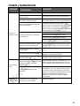
Excesivo y prolongado uso del aire.
CAUSA POSIBLE
PROBLEMA
La presión es
baja o no hay
suficiente aire.
Cierre la válvula de drenaje.
Compruebe los accesorios con agua jabonosa. Apriete
o vuelva a sellar accesorios con fugas (aplique cinta
fontanero s en las roscas). No apriete en exceso.
Limpie o reemplace el filtro de aire.
SOLUCIONES
La válvula de drenaje del tanque está
abierta.
Hay una fuga en uno de los accesorios.
La toma de aire está restringido.
Hay un agujero en la manguera de aire.
Hay condensación en el tanque de aire
causada por un alto nivel de atmosférica
humedad o porque el compresor de aire
no ha estado funcionando el tiempo
suficiente.
Las filtraciones de tanques.
La ventilación es insuficiente.
Superficies de enfriamiento están sucias.
Hay humedad en
el aire de
descarga.
Reduzca la cantidad de aire que se utiliza.
Revise la manguera de aire y reemplazarlo si es
necesario.
Sustituya el depósito inmediatamente. No intente
repararlo.
Ubicar el compresor a un área con fresco, seco y aire
bien distribuido.
Limpiar todas las superficies de enfriamiento en la
bomba y el motor a fondo.
Reemplace las piezas desgastadas y montaje usando
nueva cinta de plomero.
El compresor se
sobrecalienta.
Compruebe si las piezas desgastadas y reemplazarlos si
es necesario.
Vaciar el tanque de aire después de cada uso. Vaciar el
tanque de aire más a menudo en clima húmedo y utilizar
un filtro de línea de aire.
La válvula tiene una fuga.
La válvula tiene una fuga.
Not for Reproduction

17
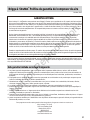
Briggs & Stratton Política de garantía del compresor de aire
Octubre, 2015
TM
Esta garantía limitada no incluye lo siguiente:
GARANTÍA LIMITADA
A. Las piezas que están desgastadas o rotas o que se han vuelto inoperantes debido al abuso, mal uso, daño accidental,
negligencia o falta de correcta instalación, operación o mantenimiento (como se indica en las instrucciones del manual o de
funcionamiento del dueño es aplicable) o el producto que se ha utilizado para fines industriales, profesionales, comerciales o
de alquiler;
B. El desgaste normal o piezas de desgaste o accesorios que pueden ser suministrados con el producto que se espera que sea
ineficaz o inutilizable después de un período razonable de uso;
C. Mantenimiento rutinario y elementos consumibles tales como, pero no limitado a los combustibles, lubricantes, válvulas,
cinturones, botones, frutos secos, fluidos, puestas a punto, o ajustes;
D. Los daños causados por reparaciones realizadas o intentadas por personas no autorizadas por el fabricante;
E. producto que se vendió al comprador original como reacondicionado o producto reformado (a menos que se especifique lo
contrario por escrito);
F. Producto o partes del mismo o si alguna parte de otro fabricante se ha instalado o reparaciones o alteraciones han sido
realizadas o intentadas por personas no autorizadas;
G. Deterioro normal del acabado exterior tales como, pero no limitado a, los arañazos, abolladuras, astillas de pintura, ni ninguna
corrosión o decoloración por el calor, de limpieza abrasivos y químicos;
H. partes componentes vendidos por e identificados como el producto de otra empresa, que será cubierto por la garantía del otro
fabricante del producto, en su caso.
Estos son nuestros términos de garantía estándar, pero en ocasiones puede haber cobertura de la garantía adicional que no fue
determinado en el momento de su publicación. Para obtener una lista de los términos de garantía actuales para su compresor de
aire, vaya a BRIGGSandSTRATTON.COM
Alton Industry Co. Ltd garantiza este producto marca Briggs & Stratton por un período de un año a partir de la fecha original
de la compra contra defectos en materiales y mano de obra. Este producto está sujeto a las condiciones y limitaciones que se
describen a continuación, si Alton Industry Co. Ltd determina este producto está cubierto por esta garantía, será reemplazado
por el mismo modelo o uno de igual valor o especificación, a la elección de Alton Industry Co. Ltd. Alton Industry Co. Ltd se
hará cargo del costo de el reemplazamiento. El comprado debe ponerse en contacto con Alton Industry Co. Ltd® para todas
las autorizaciones de garantía.
No hay ninguna otra garantía expresa. Las garantías implícitas, incluyendo las de comerciabilidad y adecuación para un fin
determinado, están limitadas a un año, o en la medida permitida por la ley. La responsabilidad por daños incidentales o
consecuentes se excluyen en la medida de exclusión está permitida por la ley. Algunos estados o países no permiten
limitaciones en la duración de la garantía y algunos estados de los países no permiten la exclusión o limitación de daños
incidentales o consecuentes, la limitación y la exclusión anterior puede no aplicarse en su caso. Esta garantía le da derechos
legales específicos y usted también puede tener otros derechos que varían de un estado a otro o de un país a otro. Guarde su
comprobante de recibo de compra. Si usted no proporciona prueba de la fecha de compra inicial en el servicio de garantía
cuando se solicita, la fecha de fabricación del producto se utiliza para determinar el período de garantía.
Guarde su comprobante de recibo de compra. Si usted no tiene prueba de la fecha de compra inicial en el servicio de garantía
cuando se solicita, la fecha de fabricación del producto se utiliza para determinar el período de garantía. Registro del producto
no obligatorio para obtener el servicio de garantía de Briggs & Stratton productos.
TM
Para preguntas acerca de nuestra garantía sobre este producto, póngase en contacto con nosotros en:
Alton Industry LTD. Group
1031 North Raddant Road
Batavia Illinois 60510
888-899-0146
www.altonindustries.com
Not for Reproduction

BRIGGSandSTRATTON.COM18
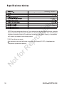
* CFM: Pies cúbicos por minuto.
Este compresor tiene una clasificación de acuerdo con la norma ISO 1217, el desplazamiento
Compresores pruebas de aceptación.
NOTA: Evite usar extensiones eléctricas. So no puede evitar usar una extensión eléctrica, exta debe
tener un tamaño de cable mínimo de 14 AWG y una longitud menor a 9,14m. Solo use extensiones
eléctricas con puesta a tierra de 3 conductores que tengan in enchufe de 3 aspas y un receptáculo
de 3 ranuras que acepten el enchufe del producto.
Especificaciones técnicas
Transmisión directa sin aceite,De una fase
074026-00 / 3301841
3/4 HP
120/5,7/60
6,8 Iitros
95 PSI
125 PSI
0,067
0,050
SJT 18 AWG /1,83 m de largo
Not for Reproduction

19
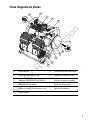
Vista detallada
Not for Reproduction

BRIGGSandSTRATTON.COM20
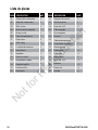
Lista da piezas
Cubierta del condensador
Retén del condensador
Filtro de aire
Bomba / motor asamblea
Tubo de transferencia
Acoplamiento rápido
La válvula de retención
Cable clamp
Derecho codo
Empuñadura
Regulador
Panel de control
Crimp copa
Tornillo m4x10 Tuerca m6
Regulador perilla
Tubo sangrado
Válvula de alivio
Tuvo sangredo
Enchufe
Válvula de bola
Rubber foot
Perno m6 × 12
Cojín cojín
Condensador
Lavadora
Conmutador de presión
Cable de alimentación
17
18
19
20
21
22
23
24
25
26
27
28
29
30
Manguera de caucho
Perno m6 × 12
01
02
03
04
05
06
07
08
09
10
11
12
13
14
15 31
1
2
1
1
1
1
2
1
1
1
1
1
2
1
Manómetro
16
2
Enchufe
32
2
3
1
1
8
1
1
2
1
1
1
4
4
1
4
4
4
DESCRIPCIÓN CANT.PIEZA
DESCRIPCIÓN
CANT.PIEZA
Not for Reproduction
-
 1
1
-
 2
2
-
 3
3
-
 4
4
-
 5
5
-
 6
6
-
 7
7
-
 8
8
-
 9
9
-
 10
10
-
 11
11
-
 12
12
-
 13
13
-
 14
14
-
 15
15
-
 16
16
-
 17
17
-
 18
18
-
 19
19
-
 20
20
-
 21
21
-
 22
22
-
 23
23
-
 24
24
-
 25
25
-
 26
26
-
 27
27
-
 28
28
-
 29
29
-
 30
30
-
 31
31
-
 32
32
-
 33
33
-
 34
34
-
 35
35
-
 36
36
-
 37
37
-
 38
38
-
 39
39
-
 40
40


Simplicity 074026-00 Manual de usuario
- Categoría
- Compresores de aire
- Tipo
- Manual de usuario
- Este manual también es adecuado para
en otros idiomas
- English: Simplicity 074026-00 User manual
Artículos relacionados
-
Simplicity 074086-00 Manual de usuario
-
-
-
-
Simplicity 074065-00 Manual de usuario
-
-
-
-
-