
Scan the code, or visit go.lifetime.com/60341-assembly
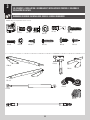
TOOLS REQUIRED TABLE OF CONTENTS
7/16" (11 mm)
1/2" (13 mm)
5/16" (8 mm) Wood Drill Bit
5/16" (8 mm) Masonry Drill Bit
Electric Drill Hammer Drill
CONTACT LIFETIME CUSTOMER SERVICE:
Call: 1-800-225-3865 Live Chat: www.lifetime.com/customerservice
(click on "LIVE CHAT" tab)
QUESTIONS?
MODEL# AND PRODUCT ID (both are needed when contacting us)
Model Number: 60341
Product ID:
BEFORE ASSEMBLY:
• Assemble on a level surface
• At least 3 people are recommended for setup
Pour le français, voir la page 2. Para el español, ver la página 3.
ASSEMBLY INSTRUCTIONS
HORIZONTAL STORAGE
SHED
MODEL 60341
FOR DOMESTIC USE ONLY!
IMPORTANT, RETAIN FOR FUTURE REFERENCE: READ CAREFULLY.
For Customer Service in mainland Europe and the United Kingdom:
E-mail: [email protected]
Icon Legend................................4
Warnings & Notices.....................5
Parts Identifi er............................6
Floor & Wall Assembly..................8
Door Assembly..........................21
Lid Assembly............................33
Storage Shed Anchoring............48
Cleaning & Care........................51
Registration..........................52
Warranty.................................53
WATCH THE HOW-TO ON YOUTUBE
YouTube® and the YouTube logo are trademarks of Google, LLC.

2
Scanner le code, ou visiter go.lifetime.com/60341-assembly
OUTILS REQUIS SOMMAIRE
7/16 po (11 mm)
1/2 po (13 mm)
5/16 po (8 mm) Mèche à boit
5/16 po (8 mm) Mèche à maçonnerie
Perceuse électrique Perceuse à percussion
CONTACTER AUX SERVICES À LA CLIENTÈLE LIFETIME® :
Composer le 1-800-225-3865 t’Chat en direct: www.lifetime.com/customerservice
(cliquer sur la languette « LIVE CHAT »)
QUESTIONS ?
N° DE MODÈLE ET RÉFÉRENCE DU PRODUIT
(il faut avoir les deux lorsque vous nous contactez)
N° de modèle : 60341
Référence du produit :
AVANT L’ASSEMBLAGE :
• Assembler sur une surface de niveau
• Nous recommandons, au moins, 3 adultes pour
l’assemblage
For English, see page 1. Para el español, ver la página 3.
INSTRUCTIONS D’ASSEMBLAGE
ABRI DE
RANGEMENT
MODÈLE n° 60341
POUR USAGE DOMESTIQUE SEULEMENT !
IMPORTANT, CONSERVER POUR RÉFÉRENCE : LIRE AVEC PRUDENCE !
Pour nos services à la clientèle du continent européen et au Royaume-Uni :
É-mail : [email protected]
Légende des icônes.........................4
Avertissements et avis.....................5
Identifi cateur de pièces...................6
Assemblage des murs......................8
Assemblage des portes..................21
Assemblage du couvercle..............33
Ancrage de l’abri...........................48
Nettoyage et entretien...................51
Enregistrement..............................52
Garantie......................................54
YouTube® et le logotype YouTube sont des marques déposées de Google, LLC.
REGARDER LA VIDÉO SUR YOUTUBE

3
Escanear el código, o visitar go.lifetime.com/60341-assembly
INSTRUMENTAL REQUERIDO ÍNDICE
7/16 in (11 mm)
1/2 in (13 mm)
5/16 in (8 mm) Broca para madera
5/16 in (8 mm) Broca para albañilería
Taladro eléctrico Martillo perforador
PONERSE EN CONTACTO CON LOS SERVICIOS DE CLIENTES LIFETIME®:
Marcar : 1-800-225-3865 Chat en vivo: www.lifetime.com/customerservice
(cliquear en la lengüeta «LIVE CHAT»)
¿PREGUNTAS?
MODELO E ID DEL PRODUCTO
(se necesitan los dos al contactarnos)
Número de modelo: 60341
ID del producto:
ANTES DEL ENSAMBLE:
• Ensamblar sobre una superfi cie nivelada
• Recomendamos, al menos, 3 adultos para el
ensamble
For English, see page 1. Pour le français, voir la page 2.
INSTRUCCIONES DE ENSAMBLE
CASETA / COBERTIZO DE
ALMACENAMIENTO
MODELO n° 60341
¡SÓLO PARA USO DOMÉSTICO!
¡IMPORTANTE, GUARDAR PARA FUTURA REFERENCIA: LEER CUIDADOSAMENTE!
Para nuestros servicios a clientes en el continente europeo y el Reino Unido:
Correo eléctronico: [email protected]
Leyenda de íconos......................4
Advertencias y avisos...................5
Identifi cador de piezas................6
Ensamble de los muros...............8
Ensamble de las puertas...........21
Ensamble del tapón..................33
Anclaje de la caseta....................48
Limpieza y cuidado...................51
Registro...................................52
Garantía...................................55
YouTube® y el logotipo YouTube son marcas registradas de Google, LLC.
MIRAR EL VIDEO EN YOUTUBE

4
• Indicates the parts/no parts required for a section.
• Indique les pièces à utiliser/qu’aucone pièce n’est requise pour une section.
• Indica las piezas que se usarán/que no necesitan en una sección.
• Indicates special heed should be taken when reading.
• Indique qu’une attention spéciale doit être portée à la lecture.
• Indica que uno debe prestar atención al leer.
• Indicates the hardware to be used for a section.
• Indique la quincaillerie à utiliser pour une section.
• Indica los artículos de ferretería que se usarán para una sección.
• Indicates the tools to be used for a section.
• Indique les outils à utiliser pour une section.
• Indica las herramientas que se utilizarán para una sección.
• Indicates the number of adults required to perform a specifi c step, e.g., 2, 3, 4, etc.
• Indique le nombre d’adultes requis pour e ectuer une étape spécifi que, p. ex., 2, 3, 4, etc.
• Indica el número de adultos requeridos para realizar un paso específi co, p.ej., 2, 3, 4, etc.
• Indicates no hardware required for a specifi c page or section.
• Indique qu’aucun matériel n’est requis pour une page précise.
• Indica que no se necesitan los artículos de ferretería para una página específi ca.
• Indicates to use/not use an electric drill for a specifi c step.
• Indique quand utiliser une/que ne pas utiliser de perceuse électrique pour une étape précise.
• Indica la utilización de/que no utilizar un taladro eléctrico para un paso específi co.
ICON LEGEND / LÉGENDE DES ICÔNES / SIGNIFICADO DE LOS ÍCONOS
• These nuts are centerlock nuts. They are designed to be tight; therefore, they will be harder to tighten. Tighten until fl ush with the metal or plastic.
• Ces écrous sont des écrous de blocage central. Ils sont conçus pour être serrés; de ce fait, ils seront plus di ciles à resserrer. Serrer jusqu’à ce qu’ils
soient au ras du métal ou du plastique.
• Estas tuercas son tuercas de bloqueo central. Están diseñadas para estar apretadas; por lo tanto, serán más difíciles de apretar. Apriételas hasta que
estén al ras del metal o plástico.

5
English:
• Failure to follow these warnings may result in serious injury or property damage and will void warranty.
• To ensure safety, do not attempt to assemble this product without following the instructions carefully.
• You must provide a platform on which to assemble your shed. The surface on which you build and set your shed must be
level. If the surface is not properly leveled, the shed will not assemble correctly. Proper surface leveling will save you time
in the long run—so please do not ignore this step. The top surface of the platform you choose must be slightly above ground level in
order to avoid water pooling inside the shed.
• Be aware that plastic pieces can be damaged by overtightening the screws. To avoid damage, we strongly recommend
the use of a drill with a low torque setting. A #2 Phillips screwdriver may also be used.
• Three capable adults are required for assembly.
• All who participate in the assembly process should wear safety glasses throughout the assembly.
• Failure to anchor the shed may result in property damage and/or personal injury. See instructions later in this manual.
• In heavy snowfall areas, we recommend removing snow from the roof.
• Do not use or store hot objects near the product.
• Proper and complete assembly are essential to reduce the risk of accident or injury.
• Most injuries are caused by misuse and/or not following instructions. Use caution when using this product.
Français :
• Le non-respect de ces avertissements peut entraîner en conséquence des blessures sérieuses ou dommages à la propriété et annulera la
garantie.
• Pour assurer la sécurité, ne pas tenter d’assembler ce produit sans suivre attentivement les instructions.
• Il faut construire une plate-forme sur laquelle vous devez assembler votre abri. La surface sur laquelle l’abri est posé doit
être de niveau. Si la surface n’est pas correctement nivelée, l’assemblage de l’abri ne se joindra pas correctement. On
gagnera du temps sur le long terme grâce à une surface bien nivelée — ne pas négliger cette étape. La plate-forme choisie
doit être construite au-dessus du sol afi n d’éviter l’accumulation d’eau à l’intérieur de l’abri.
• Il est possible d’endommager les pièces en plastique en serrant les vis excessivement. Pour éviter d’endommager le
plastique, il est fortement recommandé d’utiliser une perceuse électrique de faible puissance. Un tournevis cruciforme nº
2 peut aussi être utilisé.
• Trois adultes capables sont requis pour assembler ce produit.
• Tout ceux qui participent au processus de l’assemblage doivent porter des lunettes de sécurité tout au long de
l’assemblage.
• Si vous n’ancrez pas votre abri, des dommages à la propriété et/ou des blessures peuvent en résulter. Voir les instructions plus
tard dans ce manuel.
• Dans les régions de grosses chutes de neige, nous recommandons que vous enleviez la neige du toit.
• Ne pas utiliser ou entreposer des objets chauds dans/sur ce produit.
• L’assemblage correct et complet est essentiel pour réduire le risque des dangers ou des blessures.
• La plupart des blessures sont causées par l’abus et/ou par le non-respect des instructions. Faire attention pendant l’utilisation de ce produit.
Español:
• El incumplimiento de seguir estas advertencias puede resultar en lesiones graves o daño a la propiedad y anulará la garantía.
• Para asegurar la seguridad, no intente armar este producto sin seguir detenidamente las instrucciones.
• Es preciso construir una plataforma sobre la cual usted debe ensamblar su caseta. La superfi cie en la cual usted
ensembla y coloca su cobertizo debe estar nivelada. Si la superfi cie no está nivelada de manera adecuada, el cobertizo
horizontal no podrá ensamblarse correctamente. La nivelación de la superfi cie le ahorrará tiempo de trabajo, por lo tanto,
le pedimos que no ignore este paso. La plataforma debe ser construida arriba del suelo para evitar el afl ujo de agua dentro de la
caseta.
• Es posible endañar las piezas de plástico por apretar los tornillos. Para evitar dañar el plástico, recomendamos que use
un taladro eléctrico de baja potencia. Se puede usar también un destornillador de punta Phillips n°. 2.
• Tres adultos competentes son requeridos para ensamblar el producto.
• Todos los que participan en el ensamble del producto deben llevar gafas de seguridad a lo largo del ensamble.
• No anclar la caseta puede resultar en daños a la propiedad y/o en lesiones personales. Vea las instrucciones más adelante
en este manual.
• En las áreas de nevadas fuertes, recommendamos que quite la nieve del tejado.
• No use ni almacene objetos calientes en el producto.
• El armado propio y completo son esenciales para reducir el riesgo de accidentes y lesiones.
• La mayoría de las lesiones son causadas por el uso erróneo y/o el incumplimiento de seguir las instrucciones. Tenga cuidado al usar este
producto.
WARNINGS & NOTICES / AVERTISSEMENTS ET AVIS / ADVERTENCIAS Y AVISOS
5

6
PARTS IDENTIFIER / IDENTIFICATEUR DE PIÈCES / IDENTIFICADOR DE PIEZAS
Plastic Parts / Pièces en plastique / Piezas de plástico
Metal Parts / Pièces en métal / Piezas de metal
DRK (x1) DRJ (x1) AGO (x1) AGZ (x1)
DRI (x1)
AHD (x2)
AGL (x2)
AGN (x1) AGY (x1)
DRH (x1)
EUL (x1)
EXM (x1)
EUM (x2)
FPA (x2)
FZL (x1)
FZK (x1)

7
Metal Parts / Pièces en métal / Piezas de metal
PARTS IDENTIFIER / IDENTIFICATEUR DE PIÈCES / IDENTIFICADOR DE PIEZAS
Hardware Bags / Sacs de quincaillerie / Bolsas de herraje
DXU EYI EUH
EWT (x1) EWU (x1)
EWV (x1) EWW (x1)
!
!

8
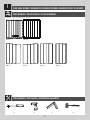
1FLOOR & WALL ASSEMBLY / ASSEMBLAGE DU PLANCHER ET DES MURS / ENSAMBLE DEL PISO Y DE LOS MUROS
EWT (x1) EWU (x1)
EWV (x1) EWW (x1)
Metal Parts / Pièces en métal / Piezas de metal
PARTS REQUIRED / PIÈCES REQUISES / PIEZAS REQUERIDAS
HARDWARE REQUIRED / QUINCAILLERIE REQUISE / HERRAJE REQUERIDO
!
!
BHJ (x2)
DUL (x2)
ADZ (x22)
ASF (x12) EEV (x1)
AYR (x2)
Blister Pack / Blister / Blíster
EYI

9
1FLOOR & WALL ASSEMBLY / ASSEMBLAGE DU PLANCHER ET DES MURS / ENSAMBLE DEL PISO Y DE LOS MUROS
(1) (1)(1) (1)
TOOLS REQUIRED / OUTILS REQUIS / INSTRUMENTAL REQUERIDO
PARTS REQUIRED / PIÈCES REQUISES / PIEZAS REQUERIDAS
DRI (x1)
AHD (x2)
AGL (x2)
AGN (x1) AGY (x1)
DRH (x1)
Plastic Parts / Pièces en plastique / Piezas de plástico

10
TOOLS & HARDWARE REQUIRED / OUTILS ET QUINCAILLERIE REQUIS / INSTRUMENTAL Y HERRAJE REQUERIDOS
X SECTION 1 (CONTINUED) / SECTION 1 (SUITE) /SECCIÓN 1 (CONTINUACIÓN)
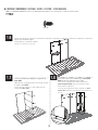
• Insert the tabs at the bottom of Wall Panel (AHD)
into the 3rd, 4th, and 5th slots from the right, rear
corner of the Floor.
• Insérez les languettes au bord inférieur du
panneau mural (AHD) dans les 3e, 4e, et 5e fentes
du côté arrière droit du
plancher.
• Inserte las lengüetas al
borde inferior del panel
mural (AHD) dentro de las
3ª, 4ª, y 5ª ranuras del
lado trasero derecho del
piso.
AHD
DRH
DRI
AYR (x2)
• Insert the Screws (AYR) into the divots in the Floor
Panels to secure them together.
• Insérez les vis (AYR) dans les marques dans les
panneaux de plancher pour attacher l’un á l’autre.
• Inserte los tornillos (AYR) en las marcas en los
paneles de piso para sujetarlos el uno al otro.
• Lay the Left Floor Panel (DRI) fl at. Slide the tabs in the Right Floor panel (DRH) between those in the Left Floor Panel,
pushing against the Left Panel as you lay the Right Panel fl at.
• Mettez le panneau de plancher gauche (DRI) à plat. Faites
glisser les languettes du panneau de plancher droit (DRH) entre
celles du panneau de plancher gauche, en poussant contre
le panneau gauche pendant que vous mettez le panneau
droit à plat.
• Aplane el panel de piso izquierdo (DRI). Deslice las lengüetas
en el panel de piso derecho (DRH) entre ellas en el panel de piso
izquierdo, empujando contra el panel izquierdo mientras
que aplane el panel derecho.
AYR
AYR AYR
AYR
1.2
• If you have trouble with this section, follow the code below to view a video on how to assemble this section.
• Si vous avez des problèmes avec cette section, suivez le code en bas pour voir un vidéo sur l’assemblage de cette section.
• Si tiene problemas con esta sección, siga el código debajo para ver un video sobre el ensamble de esta sección.
1.1
1.3
http://go.Lifetime.com/60341-section1

11
TOOLS & HARDWARE REQUIRED / OUTILS ET QUINCAILLERIE REQUIS / INSTRUMENTAL Y HERRAJE REQUERIDOS
X SECTION 1 (CONTINUED) / SECTION 1 (SUITE) /SECCIÓN 1 (CONTINUACIÓN)
• Slide the panel to the left.
• Faites glisser le panneau à gauche.
• Deslice el panel a la izquierda.
AHD
• Insert the tabs at the bottom of the second Wall Panel
(AHD) into the three slots to the left of the fi rst Wall Panel.
• Insérez les languettes au bord inférieur du deuxième
panneau mural (AHD) dans les trois fentes à gauche du
premier panneau mural.
• Inserte las lengüetas al borde inferior del segundo panel
mural (AHD) dentro de las tres ranuras a la izquierda del
primer panel mural.
1.4
1.5

12
TOOLS & HARDWARE REQUIRED / OUTILS ET QUINCAILLERIE REQUIS / INSTRUMENTAL Y HERRAJE REQUERIDOS
X SECTION 1 (CONTINUED) / SECTION 1 (SUITE) / SECCIÓN 1 (CONTINUACIÓN)
ADZ (x4)
ADZ
ADZ
ADZ
ADZ
AGL
• Slide the panel to the right.
• Faites glisser le panneau à droite.
• Deslice el panel a la derecha.
• Secure the two Panels together using four (4)
Screws (ADZ).
• Attachez les deux panneaux l’un à l’autre à l’aide
de quatre (4) vis (ADZ).
• Sujete los dos paneles el uno al otro usando
cuatro (4) tornillos (ADZ).
• Insert the tabs at the bottom of the Corner panel
(AGL) into the fi rst two slots in the Floor.
• Insérez les languettes au bord inférieur du
panneau angulaire (AGL) dans les premières deux
fentes dans le plancher.
• Inserte las lengüetas al borde inferior del panel
angular (AGL) dentro de las primeras dos ranuras en
el piso.
1.7 1.8
1.6

13
TOOLS & HARDWARE REQUIRED / OUTILS ET QUINCAILLERIE REQUIS / INSTRUMENTAL Y HERRAJE REQUERIDOS
X SECTION 1 (CONTINUED) / SECTION 1 (SUITE) / SECCIÓN 1 (CONTINUACIÓN)
• Tilt the panel as you bend it to get it in front of
the rear panel.
• Inclinez le panneau angulaire lorsque vous le pliez,
et positionnez-le devant le panneau arrière.
• Incline el panel al doblarlo para colocarlo en
frente del panel trasero.
ADZ
ADZ
ADZ
ADZ
ADZ (x4)
• Slide the panel forward.
• Faites glisser le panneau en avant.
• Deslice el panel hacia delante.
1.11
1.10
1.9
• Pull down on the panel to insert the two tabs at the
bottom of the panel into the slots in the Floor panel.
Secure with four (4) Screws (ADZ).
• Tirez sur le panneau pour insérer les deux languettes
au bord inférieur dans les fentes dans le plancher.
Attachez les panneaux l’un à l’autre à l’aide de quatre
(4) vis (ADZ).
• Tire el panel para abajo e inserte las dos lengüetas al
borde inferior adentro de las ranuras en el piso. Sujete
los paneles el uno al otro con cuatro (4) tornillos (ADZ).

14
TOOLS & HARDWARE REQUIRED / OUTILS ET QUINCAILLERIE REQUIS / INSTRUMENTAL Y HERRAJE REQUERIDOS
X SECTION 1 (CONTINUED) / SECTION 1 (SUITE) / SECCIÓN 1 (CONTINUACIÓN)
AGN
ADZ (x12)
ADZ
ADZ
ADZ
ADZ
AGL
AGY
• Repeat steps 1.9–1.11 for the left side.
• Répétez les étapes 1.9 – 1.11 pour le côté gauche.
• Repita los pasos 1.9–1.11 para el lado izquierdo.
• Slide the panel toward the back, and secure it to
the Rear Corner Wall Panel with four (4) Screws (ADZ).
• Faites glisser le panneau en arrière, et attachez-
le au panneau mural angulaire arrière à l’aide de
quatre (4) vis (ADZ).
• Deslice el panel hacia atrás, y sujételo al panel
mural angular trasero con cuatro (4) tornillos (ADZ).
• Repeat steps 1.13–1.14 for the left side.
• Répétez les étapes 1.13 – 1.14 pour le côté gauche.
• Repita los pasos 1.13–1.14 para el lado izquierdo.
• Insert the three tabs at the bottom of Corner panel
(AGY) into the slots in the Floor.
• Insérez les trois languettes au bord inférieur
du panneau angulaire (AGY) dans les fentes dans le
plancher.
• Inserte las lengüetas al borde inferior del panel
angular (AGY) dentro de las ranuras en el piso.
1.14 1.15
1.13
1.12

15
TOOLS & HARDWARE REQUIRED / OUTILS ET QUINCAILLERIE REQUIS / INSTRUMENTAL Y HERRAJE REQUERIDOS
X SECTION 1 (CONTINUED) / SECTION 1 (SUITE) /SECCIÓN 1 (CONTINUACIÓN)
EWV
EWW
Hole on top
Trou vers le haut
Agujero para arriba
Hole on top
Trou vers le haut
Agujero para arriba
Hole on top
Trou vers le haut
Agujero para arriba
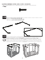
• Flip the assembly on its back.
• Renversez l’assemblage.
• Vuelque el ensamble.
• Bend the Corner Panels as shown. Insert the Tube Support Assembly into the holes in the bottom of the Floor
Panels. Continue to step 1.19.
• Pliez les panneaux angulaires comme illustré. Insérez l’ensemble des tubes de support dans les trous à la partie
inférieure du plancher. Suivez à l’étape 1.19.
• Doble los paneles angulares como se muestra. Inserte el conjunto de los tubos de soporte en los agujeros a la
parte inferior del piso. Siga al paso 1.19.
• Attach the two Vertical Support Tubes (EWV & EWW).
• Attachez les deux tubes de support verticaux (EWV et
EWW).
• Conecte los dos tubos de soporte verticales (EWV y
EWW).
1.18
1.17
1.16

16
TOOLS & HARDWARE REQUIRED / OUTILS ET QUINCAILLERIE REQUIS / INSTRUMENTAL Y HERRAJE REQUERIDOS
X SECTION 1 (CONTINUED) / SECTION 1 (SUITE) / SECCIÓN 1 (CONTINUACIÓN)
BHJ (x1)
90°
90°
1.19
!
!
• Slide the Tubes into the Wall Panels until the Tubes hang out about 6" (15 cm). Adjust the width of the Tubes
to accommodate the holes in the Floor Panels, then insert the Self-Drilling Screw (BHJ). Finally, insert the Tubes until
fl ush with the Floor Panels.
• Faites glisser les tubes dans les panneaux muraux jusqu’à ce que les tubes dépassent de 15 cm (6 po). Ajustez
la largeur des tubes pour accommoder les trous dans le plancher. Ensuite, insérez la vis autoperforante (BHJ). Enfi n,
insérez les tubes jusqu’à ce qu’ils soient à ras du plancher.
• Deslice los tubos a través de los agujeros en el piso y dentro de los paneles murales hasta que los tubos
sobresalgan del piso aproximadamente 15 cm (6 in). Ajuste la anchura de los tubos para acomodar los agujeros en
los paneles de piso. Entonces, inserte el tornillo auto-perforante (BHJ). Por último, inserte los tubos hasta que estén a
ras de los paneles de piso.
Note: It is OK if there is a gap here. Just ensure the corners of the Tubes are at 90°.
Remarque : Ce n’est pas grave s’il y a un espace entre les deux tubes. Assurez-vous que les coins forment des angles de 90°.
Nota: Está bien si hay un espacio entre los dos tubos. Asegúrese que los rincones forman ángulos de 90°.
Note: If the hole is not here, pull the Tubes out and turn them around 180°.
Remarque : Si le trou n’est pas ici, sortez les tubes et tournez-les 180°.
Nota: Si el agujero no está aquí, retire los tubos y gírelos 180°.
BHJ
BHJ

17
TOOLS & HARDWARE REQUIRED / OUTILS ET QUINCAILLERIE REQUIS / INSTRUMENTAL Y HERRAJE REQUERIDOS
X SECTION 1 (CONTINUED) / SECTION 1 (SUITE) / SECCIÓN 1 (CONTINUACIÓN)
1.1
EWT
EWU
ASF
ASF
ASF
ASF ASF
ASF
ASF (x6)
1.20
1.21
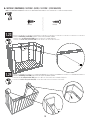
• Attach the two Horizontal Support Tubes (EWT & EWU).
• Attachez les deux tubes de support horizontaux (EWT et EWU).
• Conecte los dos tubos de soporte horizontales (EWT y EWU).
• Turn the assembly upright. Place the Horizontal Support Tubes down into the shed and align the holes the Tubes
with those in the Wall Panels. Insert three (3) Screws (ASF) into the left Wall and three (3) into the right Wall.
• Redressez l’assemblage. Insérez l’ensemble des tubes de support dans l’assemblage et alignez les trous dans les
tubes avec ceux des panneaux muraux. Insérez trois (3) vis (ASF) dans le côté gauche et trois (3) dans le côté droit.
• Ponga el ensamble vertical. Inserte el conjunto de los tubos de soporte en el ensamble y alinee los agujeros en los
tubos con ellos en los paneles murales. Inserte tres (3) tornillos (ASF) en el lado izquierdo y tres (3) en el lado derecho.

18
TOOLS & HARDWARE REQUIRED / OUTILS ET QUINCAILLERIE REQUIS / INSTRUMENTAL Y HERRAJE REQUERIDOS
X SECTION 1 (CONTINUED) / SECTION 1 (SUITE) / SECCIÓN 1 (CONTINUACIÓN)
ASF ASF ASF
ASF ASF ASF
ASF (x6)
90°
90°
1.22 • Align the holes in the Rear Wall Panels with those in the Tubes. Loosely insert six (6) Screws (ASF).
Adjust rear Tubes so that the corners are at 90°. Then, tighten the Screws.
• Alignez les trous dans les panneaux muraux arrières avec ceux des tubes arrières. Insérez lâchement six (6) vis
(ASF). Ajustez les tubes arrières de sorte que les encoignures forment un angle de 90°. Ensuite, serrez les vis.
• Alinee los seis agujeros en los paneles murales traseros con los agujeros en los tubos. Sin apretar bien, inserte seis
(6) tornillos (ASF). Ajuste los tubos traseros de modo que los rincones son de 90°. Entonces, apriete los tornillos.
Note: It is OK if there is a gap here. Just ensure the corners of the Tubes are at 90°.
Remarque : Ce n’est pas grave s’il y a un espace entre les deux tubes. Assurez-vous que les coins forment des angles de 90°.
Nota: Está bien si hay un espacio entre los dos tubos. Asegúrese que los rincones forman ángulos de 90°.
!

19
TOOLS & HARDWARE REQUIRED / OUTILS ET QUINCAILLERIE REQUIS / INSTRUMENTAL Y HERRAJE REQUERIDOS
X SECTION 1 (CONTINUED) / SECTION 1 (SUITE) / SECCIÓN 1 (CONTINUACIÓN)
BHJ (x1) DUL (x2)
DUL
BHJ
1.23
1.24
• Insert a Self-Drilling Screw (BHJ) into the Tubes at the location shown.
• Insérez une vis autoperforante (BHJ) dans les tubes à l’endroit indiqué.
• Inserte un tornillo auto-perforante (BHJ) en los tubos a la ubicación indicada.
• Insert a Self-Drilling Screw (DUL) into each side at the locations shown.
• Insérez une vis autoperforante (DUL) dans les côtés de l’ensemble aux endroits indiqués.
• Inserte un tornillo auto-perforante (DUL) en los dos lados a las ubicaciones indicadas.
DUL
DUL

20
TOOLS & HARDWARE REQUIRED / OUTILS ET QUINCAILLERIE REQUIS / INSTRUMENTAL Y HERRAJE REQUERIDOS
X SECTION 1 (CONTINUED) / SECTION 1 (SUITE) / SECCIÓN 1 (CONTINUACIÓN)
1.25
ADZ (x2)
ADZ
ADZ
EEV (x1)
EEV
EEV
• Set the Door Stop (EEV) onto the Floor at the location indicated and align the holes. Secure with two (2) Screws (ADZ).
• Mettez le butoir (EEV) sur le plancher à l’endroit indiqué, et alignez les trous. Attachez-le à l’aide de deux (2) vis (ADZ).
• Coloque el tope de puerta (EEV) en el piso a la ubicación indicada, y alinee los agujeros. Sujételo con dos (2) tornillos (ADZ).
Front Edge / Bord avant / Borde delantero

21
2DOOR ASSEMBLY / ASSEMBLAGE DES PORTES / ENSAMBLE DE LAS PUERTAS
EUL (x1)
EXM (x1)
EUM (x2)
AHS (x1)
BYS (x2)
BYR (x2)
ADX (x14)
AEE (x6)
ADZ (x4) BYZ (x4)
ADW (x2)
DUL (x9)
HDR (x8)
DWJ (x4)
EYJ (x1)
EOO (x1)
DXU
HARDWARE REQUIRED / QUINCAILLERIE REQUISE / HERRAJE REQUERIDO
Metal Parts / Pièces en métal / Piezas de metal
PARTS REQUIRED / PIÈCES REQUISES / PIEZAS REQUERIDAS
Hardware Bag / Sac de quincaillerie /Bolsa de herraje

22
2DOOR ASSEMBLY / ASSEMBLAGE DES PORTES / ENSAMBLE DE LAS PUERTAS
AGO (x1) AGZ (x1)
(1) (1) (1)
Plastic Parts / Pièces en plastique /Piezas de plástico
PARTS REQUIRED / PIÈCES REQUISES / PIEZAS REQUERIDAS
TOOLS REQUIRED / OUTILS REQUIS / INSTRUMENTAL REQUERIDO

23
TOOLS & HARDWARE REQUIRED / OUTILS ET QUINCAILLERIE REQUIS / INSTRUMENTAL Y HERRAJE REQUERIDOS
X SECTION 2 (CONTINUED) / SECTION 2 (SUITE) /SECCIÓN 2 (CONTINUACIÓN)
EUM
AGO
AGO
• If you have trouble with this section, follow the code below to view a video on how to assemble this section.
• Si vous avez des problèmes avec cette section, suivez le code en bas pour voir un vidéo sur l’assemblage de cette section.
• Si tiene problemas con esta sección, siga el código debajo para ver un video sobre el ensamble de esta sección.
Top Edge / Borde superior / Bord supérieur
• Attach the Lateral Support Channel (EUM) to the back of the Left Door (AGO), and align the holes.
• Attacher un canal de support latéral (EUM) au côté arrière de la porte gauche (AGO), et aligner les trous.
• Sujetar un canal de soporte lateral (EUM) al costado trasero de la puerta izquierda (AGO), y alinear los agujeros.
Note: The Handle will go here later.
Note : La poignée va ici plus tard.
Nota: El picaporte va aquí más tarde.
!
2.1
http://go.Lifetime.com/60341-section2

24
TOOLS & HARDWARE REQUIRED / OUTILS ET QUINCAILLERIE REQUIS / INSTRUMENTAL Y HERRAJE REQUERIDOS
X SECTION 2 (CONTINUED) / SECTION 2 (SUITE) / SECCIÓN 2 (CONTINUACIÓN)
ADX
ADX
ADX
ADX
ADX
2.2
ADX (x4)
• Secure the Channel using four (4) Screws (ADX).
• Attacher le canal à l’aide de quatre (4) vis (ADX).
• Sujetar el canal usando cuatro (4) tornillos (ADX).

25
TOOLS & HARDWARE REQUIRED / OUTILS ET QUINCAILLERIE REQUIS / INSTRUMENTAL Y HERRAJE REQUERIDOS
X SECTION 2 (CONTINUED) / SECTION 2 (SUITE) / SECCIÓN 2 (CONTINUACIÓN)
EXM
2.3
2.4
EYJ
ADZ
ADZ
EYJ (x1)
ADZ (x2)
• Insert the Medial Left Door Support Channel (EXM) into the groove along the medial edge of the Left Door.
• Insérer le canal de support médial pour la porte gauche (EXM) dans la rainure le long du bord médial de la porte gauche.
• Insertar el canal de soporte medial para la puerta izquierda (EXM) en la ranura a lo largo del borde mdeial de la puerta
izquierda.
• Attach the Locking Tab (EYJ) to the Left Door using the hardware included.
• Attacher la languette de verrouillage (EYJ) à la porte gauche à l’aide de la quincaillerie incluse.
• Sujetar la lengüeta de cierre (EYJ) a la puerta izquierda usando el herraje incluido.

26
TOOLS & HARDWARE REQUIRED / OUTILS ET QUINCAILLERIE REQUIS / INSTRUMENTAL Y HERRAJE REQUERIDOS
X SECTION 2 (CONTINUED) / SECTION 2 (SUITE) / SECCIÓN 2 (CONTINUACIÓN)
• Attach the Channel to the Left Door using six (6) Screws (ADX).
• Attacher le canal à la porte gauche à l’aide de six (6) vis (ADX).
• Sujetar el canal a la puerta izquierda usando seis (6) tornillos (ADX).
BYZ
BYZ
AEE AEE
BYZ (x2)
ADW (x1) AEE (x3)
2.5
2.6
BYS (x1)
BYR (x1)
BYS
BYR
AEE
ADX (x6)
ADX
ADX
ADX
ADX
ADX
ADX
• Attach the Handle (BYR & BYS) to the Left Door as
shown.
• Attacher la poignée (BYR et BYS) à la porte gauche
comme illustré.
• Sujetar el picaporte (BYR y BYS) a la puerta izquierda
como se muestra.
ADW

27
TOOLS & HARDWARE REQUIRED / OUTILS ET QUINCAILLERIE REQUIS / INSTRUMENTAL Y HERRAJE REQUERIDOS
X SECTION 2 (CONTINUED) / SECTION 2 (SUITE) / SECCIÓN 2 (CONTINUACIÓN)
2.7
HDR
HDR
HDR
HDR
HDR
HDR
HDR (x4)
DWJ (x2)
DWJ
DWJ
• These Screws (HDR) go through the Hinge, Door, and through the holes in the Channel.
• Ces vis (HDR) vont à travers la charnière, la porte, et les trous dans le canal.
• Estos tornillos (HDR) atravesan la bisagra, la puerta, y los agujeros en el canal.
Note: Chamfered side faces away from Door.
Remarque : Le côté chanfreiné doit être opposé à la porte.
Nota: El lado biselado debe dar la espalda a la puerta.
!

28
TOOLS & HARDWARE REQUIRED / OUTILS ET QUINCAILLERIE REQUIS / INSTRUMENTAL Y HERRAJE REQUERIDOS
X SECTION 2 (CONTINUED) / SECTION 2 (SUITE) / SECCIÓN 2 (CONTINUACIÓN)
AGZ
EUL
AGZ
2.9 2.10
2.8
DUL (x1)
AHS (x1)
DUL DUL
• Slide the Tube (EUL) into the Right Door (AGZ) until it hangs out about
six inches (15 cm).
• Faire glisser le tube (EUL) dans la porte droite (AGZ) jusqu’à ce qu’il
étende quinze centimètres.
• Deslizar el tubo (EUL) dentro de la puerta derecha (AGZ) hasta que
extienda unos quince centímetros.
• Insert the End Cap (AHS) into the end of the Tube.
Gently push the Tube into the Door until the Cap
is fl ush with the bottom of the Door.
• Insérer le capuchon (AHS) dans l’extrémité du
tube. Fiare glisser le tube délicatement dans la
porte jusqu’à ce qu’il soit au ras du bord inférieur
de la porte.
• Insertar el tapón (AHS) en el extremo del tubo.
Deslizar cuidadosamente el tubo en la puerta
hasta que el tapón esté a ras del borde inferior de
la puerta.
• Insert a Self-Drilling Screw (DUL) to secure the Tube
in place. If necessary, drill fi rst.
• Insérer une vis autoperforante (DUL) pour fi xer le
tube en place. Si besoin, percer en premier.
• Insertar un tornillo auto-perforante (DUL) para sujetar
el tubo en su lugar. De ser necesario, taladrar primero.
AHS

29
TOOLS & HARDWARE REQUIRED / OUTILS ET QUINCAILLERIE REQUIS / INSTRUMENTAL Y HERRAJE REQUERIDOS
X SECTION 2 (CONTINUED) / SECTION 2 (SUITE) / SECCIÓN 2 (CONTINUACIÓN)
EUM
Top Edge / Borde superior / Bord supérieur
2.11
2.12
ADX
ADX
ADX
ADX
ADX
ADX (x4)
Note: Handle goes here later.
Remarque : La poignée va ici plus tard.
Nota: El picaporte va aquí más tarde.
!
• Align the four (4) holes in this Channel (EUM) with those in the Right Door.
• Aligner les quatre (4) trous dans le canal (EUM) avec ceux dans la porte droite.
• Alinear los cuatro (4) agujeros en este canal (EUM) con ellos en la puerta derecha.
• Secure the Channel using four (4) Screws (ADX).
• Attacher le canal à l’aide de quatre (4) vis (ADX).
• Sujetar el canal usando cuatro (4) tornillos (ADX).

30
TOOLS & HARDWARE REQUIRED / OUTILS ET QUINCAILLERIE REQUIS / INSTRUMENTAL Y HERRAJE REQUERIDOS
X SECTION 2 (CONTINUED) / SECTION 2 (SUITE) / SECCIÓN 2 (CONTINUACIÓN)
AEE (x3)
BYZ (x2)
ADW (x1)
ADZ (x2) EOO (x1)
2.13
2.14
BYS (x1)
BYR (x1)
BYS
BYR
ADZ
ADZ
EOO
• Attach the Handle (BYR & BYS) to the Right Door as shown.
• Attacher la poignée (BYR et BYS) à la porte droite comme illustré.
• Sujetar el picaporte (BYR y BYS) a la puerta derecha como se muestra.
• Secure the Door Pin (EOO) to the bottom of the Right
Door as shown.
• Attacher la goupille de la porte (EOO) à la porte droite à
l’emplacement indiqué.
• Sujetar el pasador (EOO) a la puerta derecha a la
ubicación indicada.
BYZ BYZ
AEE
AEE
ADW
AEE

31
TOOLS & HARDWARE REQUIRED / OUTILS ET QUINCAILLERIE REQUIS / INSTRUMENTAL Y HERRAJE REQUERIDOS
X SECTION 2 (CONTINUED) / SECTION 2 (SUITE) / SECCIÓN 2 (CONTINUACIÓN)
2.15
DWJ DWJ
HDR
HDR
HDR HDR
DWJ (x2)
HDR (x4)
• These Screws (HDR) go through the Hinge, Door, and through the holes in the Channel.
• Ces vis (HDR) vont à travers la charnière, la porte, et les trous dans le canal.
• Estos tornillos (HDR) van a través de bisagra, la puerta, y los agujeros en el canal.
Note: Chamfered side faces away from Door.
Remarque : Le côté chanfreiné doit être opposé à la porte.
Nota: El lado biselado debe dar la espalda a la puerta.
!

32
TOOLS & HARDWARE REQUIRED / OUTILS ET QUINCAILLERIE REQUIS / INSTRUMENTAL Y HERRAJE REQUERIDOS
X SECTION 2 (CONTINUED) / SECTION 2 (SUITE) / SECCIÓN 2 (CONTINUACIÓN)
DUL (x8)
DUL
DUL
2.16
2.17
• Attach the Right Door to the assembly using Self-Drilling Screws (DUL). If necessary, drill fi rst.
• Attacher la porte droite à l’assemblage à l’aide des vis autoperforantes (DUL). Si besoin, percer en premier.
• Sujetar la puerta derecha al ensamble usando tornillos auto-perforantes (DUL). De ser necesario, taladrar primero.
• Repeat the last step for the Left Door.
• Répéter l’étape précédente pour la porte gauche.
• Repetir el paso anterior para la puerta izquierda.

33
3LID ASSEMBLY & INSTALLATION / ASSEMBLAGE ET INSTALLATION DU COUVERLE / ENSAMBLE E
INSTALACIÓN DE LA TAPA
ADZ (x6)
ADV (x2)
AHS (x2)
BHJ (x1)
BES (x6)
ADX (x15) DDL (x10)
BER (x6)
ACA (x4)
EUJ (x2)
EYN (x1)
EYK (x1)
BET (x4)
AAV (x4)
HARDWARE REQUIRED / QUINCAILLERIE REQUISE / HERRAJE REQUERIDO
Hardware Bag / Sac de quincaillerie /Bolsa de herraje
AZP (x4)
EYL (x1)
EYM (x1)
CZH (x2)
FZJ (x2)
FYU (x4)
EUH

34
3LID ASSEMBLY & INSTALLATION / ASSEMBLAGE ET INSTALLATION DU COUVERLE / ENSAMBLE E
INSTALACIÓN DE LA TAPA
(1)
(1)
(2) (2)
DRK (x1) DRJ (x1)
EYG (x2)
FZL (x1)
FZK (x1)
TOOLS REQUIRED / OUTILS REQUIS / INSTRUMENTAL REQUERIDO
7/16 in/po (≈11 mm) 1/2 in/po (≈13 mm)
Plastic Parts / Pièces en plastique / Piezas de plástico
Metal Parts / Pièces en métal /Piezas de metal
PARTS REQUIRED / PIÈCES REQUISES / PIEZAS REQUERIDAS

35
TOOLS & HARDWARE REQUIRED / OUTILS ET QUINCAILLERIE REQUIS / INSTRUMENTAL Y HERRAJE REQUERIDOS
X SECTION 3 (CONTINUED) / SECTION 3 (SUITE) /SECCIÓN 3 (CONTINUACIÓN)
ADZ (x6)
ADZ (x3)
ADZ (x3)
DRK
DRJ
3.2
3.1 • Set the edge of the Right Lid (DRJ) over the edge of the Left Lid (DRK).
• Mettre le bord du couvercle droit (DRJ) sur le bord du couvercle gauche (DRK).
• Colocar el borde de la tapa derecha (DRJ) encima del borde de la tapa izquierda (DRK).
• Align the six holes, and secure the Lid pieces together.
• Aligner les six trous, et attacher les couvercles.
• Alinear los seis agujeros, y sujetar las tapas.
http://go.Lifetime.com/60341-section3
• If you have trouble with this section, follow the code below to view a video on how to assemble this section.
• Si vous avez des problèmes avec cette section, suivez le code en bas pour voir un vidéo sur l’assemblage de cette section.
• Si tiene problemas con esta sección, siga el código debajo para ver un video sobre el ensamble de esta sección.

36
TOOLS & HARDWARE REQUIRED / OUTILS ET QUINCAILLERIE REQUIS / INSTRUMENTAL Y HERRAJE REQUERIDOS
X SECTION 3 (CONTINUED) / SECTION 3 (SUITE) / SECCIÓN 3 (CONTINUACIÓN)
EYK
EYK
AZP (x4)
ACA (x4)
EYG
EYG
3.3
3.4
AZP (x4)
EYK (x1)
ADX
ADX
ADX (x2)
• Tighten the Keeper (EYK) to the Lid Supports (EYG). Then, insert the left end of the Lid
Support into the slit in the Lid as shown.
• Serrer le loquet (EYK) aux supports du couvercle (EYG). Ensuite, insérer
l’extrémité gauche du support du couvercle dans la fente dans
le couvercle comme illustré.
• Apretar el cerradero (EYK) a los soportes de la tapa
(EYG). Entonces, introducir el extremo izquierdo del
soporte de la tapa en la ranura de la tapa como se
muestra.
• Rotate downward, lightly bow the Lid Supports, and slide the right end into the slit on the right side. Lightly insert
two (2) Screws (ADX) in the places shown. Do not completely tighten the Screws—yet. You’ll tighten these and others later.
• Tourner l’assemblage vers le bas, courbez légèrement les supports du couvercle, et faites glisser l’extrémité
droite dans l’encoche droit. Insérer légèrement deux (2) vis (ADX) dans les emplacements indiqués. Ne pas serrer
complètement les deux vis. Serrer ces vis et toutes les autres plus tard.
• Girarlo para abajo, curvee ligeramente los soportes de la tapa, y deslizar el extremo derecho dentro de la muesca
en el lado derecho. Insertar ligeramente dos (2) tornillos (ADX) en las ubicaciones indicadas. No apetar por completo
todavía los tornillos. Se apretarán estos dos y los demás más tarde.
7/16 in/po
(≈11 mm)
ACA (x4)
AZP (x4)
ADX
ADX
ACA (x4)

37
TOOLS & HARDWARE REQUIRED / OUTILS ET QUINCAILLERIE REQUIS / INSTRUMENTAL Y HERRAJE REQUERIDOS
X SECTION 3 (CONTINUED) / SECTION 3 (SUITE) / SECCIÓN 3 (CONTINUACIÓN)
ADX (x4)
EYN
3.5
3.7
3.6
BET (x2)
EYM (x1)
ADX ADX ADX ADX
• Attach the hardware to the Left Hinge (EYM), and tighten
securely.
• Attacher la quincaillerie à la charnière gauche (EYM), et
serrer-la bien.
• Sujetar el herraje a la bisagra izquierda (EYM), y apretarla
bien.
1/2 in/po (x2)
(≈13 mm) (x2)
BET
BET
AAV
AAV
EYM
EYN (x1)
• Align the holes with the points indicated.
• Aligner les trous avec les points indiqués.
• Alinear los agujeros con los puntos indicados.
• Secure with four (4) Screws (ADX) at the points indicated.
• Fixer-la à l’aide de quatre (4) vis (ADX) aux points indiqués.
• Fijarla con cuatro (4) tornillos (ADX) a los puntos indicados.
AAV (x2)

38
TOOLS & HARDWARE REQUIRED / OUTILS ET QUINCAILLERIE REQUIS / INSTRUMENTAL Y HERRAJE REQUERIDOS
X SECTION 3 (CONTINUED) / SECTION 3 (SUITE) / SECCIÓN 3 (CONTINUACIÓN)
3.8
3.9
DDL
DDL
DDL DDL
DDL
DDL (x5)
• Insert the end of the Left Hinge into the notch in the Lid, and rotate downward.
• Insérer l’extrémité de la charnière gauche dans la fente dans le couvercle, et tourner-la vers le bas.
• Insertar el extremo de la bisagra izquierda en la ranura en la tapa, y girarla para abajo.
• Align the fi ve holes in the Hinge with the four notches in the Lid. Insert the Screws (DDL) at a slight downward angle. Please use a drill and
Phillips bit for this step.
• Aligner les cinq trous dans la charnière avec les quatre encoches dans le couvercle. Insérez les vis (DDL) à un angle légèrement oblique.
Veiller à utiliser une perceuse éléctrique et un foret Phillips pour cette étape.
• Alinear los cinco agujeros en la bisagra con los cuatro muescas en la tapa. Inserte los tornillos (DDL) a un ángulo descendente. Usar un
taladro eléctrico y una broca Phillips para este paso.

39
TOOLS & HARDWARE REQUIRED / OUTILS ET QUINCAILLERIE REQUIS / INSTRUMENTAL Y HERRAJE REQUERIDOS
X SECTION 3 (CONTINUED) / SECTION 3 (SUITE) /SECCIÓN 3 (CONTINUACIÓN)
3.10 • Insert the end of the Swaged Cross Bar (FZK) into the end of Right Cross Bar (FZL) as shown. Insert an End Cap (AHS) into
each end.
• Insérer l’extrémité de la tube transversal carré étampé (FZK) dans l’extrémité de la tube transversal carré (FZL) comme
illustré. Insérer un capuchon (AHS) dans chaque extrémité.
• Insertar el extremo del travesaño cuadrado estampado (FZK) en el extremo del travesaño cuadrado (FZL) como se
muestra. Insertar un tapón (AHS) en cada extremo.
3.11 • Insert the left end of the Cross Bar into the square hole of the Left Hinge.
• Insérer l’extrémité gauche de la barre transversale dans le trou carré de la charnière gauche.
• Insertar el extremo izquierdo del travesaño en el agujero cuadrado de la bisagra izquierda.
FZK
AHS
AHS
FZL
AHS (x2)

40
TOOLS & HARDWARE REQUIRED / OUTILS ET QUINCAILLERIE REQUIS / INSTRUMENTAL Y HERRAJE REQUERIDOS
X SECTION 3 (CONTINUED) / SECTION 3 (SUITE) / SECCIÓN 3 (CONTINUACIÓN)
3.12
3.13
• Rotate the Crossbar downward.
• Tourner la barre transversale vers le bas.
• Girar el travesaño hacia abajo.
• Ensure the two holes in the Crossbar align with those in the Lid, and insert a Screw (BHJ) into the the Crossbar at
the location shown to secure the two halves together.
• Veiller à ce que les deux trous dans la barre transversale s’alignent avec ceux du couvercle, et insérer une vis
(BHJ) à l’endroit indiqué afi n de fi xer les deux pièces du couvercle l’une l’autre.
• Asegurar que los dos agujeros del travesaño se alinean con ellos de la tapa, e insertar un tornillo (BHJ) en el
travesaño a la ubicación indicada para fi jar las dos piezas la una a la otra.
Holes / Trous / Agujeros
Square Hole / Trou carré / Agujero cuadrado
Holes / Trous / Agujeros
BHJ (x1)
BHJ

41
TOOLS & HARDWARE REQUIRED / OUTILS ET QUINCAILLERIE REQUIS / INSTRUMENTAL Y HERRAJE REQUERIDOS
X SECTION 3 (CONTINUED) / SECTION 3 (SUITE) / SECCIÓN 3 (CONTINUACIÓN)
BET (x2)
DDL (x5)
EYL (x1)
3.14
3.15
1/2 in/po (x2)
(≈13 mm) (x2)
• Insert the Crossbar into the Right Hinge, and repeat steps 3.8–3.9 for the right side. Then, rotate the hinges to 90° angles. Please
use a drill and Phillips bit for this step.
• Répéter les étapes 3.8–3.9 pour le côté droit. Ensuite, tournez les charnières à 90°. Veiller à utiliser une perceuse éléctrique et un
foret Phillips pour cette étape.
• Repetir los pasos 3.8 – 3.9 para el lado derecho. Entonces, rote las bisagras a ángulos de 90°. Usar un taladro eléctrico y una
broca Phillips para este paso.
• Attach the hardware to the Right Hinge (EYL), and tighten securely.
• Attacher la quincaillerie à la charnière droite (EYL), et serrer-la bien.
• Sujetar el herraje a la bisagra derecha (EYL), y apretarlos bien.
BET
BET
AAV
AAV
EYL
AAV (x2)

42
TOOLS & HARDWARE REQUIRED / OUTILS ET QUINCAILLERIE REQUIS / INSTRUMENTAL Y HERRAJE REQUERIDOS
X SECTION 3 (CONTINUED) / SECTION 3 (SUITE) / SECCIÓN 3 (CONTINUACIÓN)
3.16 • With the holes in the Crossbar aligned with those in the Lid, insert two (2) Screws (ADV) to secure the Crossbar in
place. Rotate the Hinges upright.
• Avec les trous dans la barre transversale alignés avec ceux du couvercle, insérer deux (2) vis (ADV) pour fi xer la
barre transversale en place. Tourner les charnières verticales.
• Con los agujeros en el travesaño alineados con ellos en la tapa, insertar dos (2) tornillos (ADV) para fi jar el
travesaño en su lugar. Girar las bisagras verticales.
ADV (x2)
ADV
ADV

43
TOOLS & HARDWARE REQUIRED / OUTILS ET QUINCAILLERIE REQUIS / INSTRUMENTAL Y HERRAJE REQUERIDOS
X SECTION 3 (CONTINUED) / SECTION 3 (SUITE) / SECCIÓN 3 (CONTINUACIÓN)
3.17 • Secure the two (2) Padeyes (CZH) to the Lid using two (2) Screws (FYU) each at the locations shown. Do not overtighten.
• Fixer les deux (2) platines à œil (CZH) au couvercle à l’aide de deux (2) vis (FYU) chacun aux endroits indiqués. Ne pas trop serrer.
• Fijar los dos (2) pasacables (CZH) a la tapa usando dos (2) tornillos (FYU) cada uno a las ubicaciones indicadas. No apretar
demasiado.
CZH (x2)
CZH
FYU (x4)
FYU
FYU

44
TOOLS & HARDWARE REQUIRED / OUTILS ET QUINCAILLERIE REQUIS / INSTRUMENTAL Y HERRAJE REQUERIDOS
X SECTION 3 (CONTINUED) / SECTION 3 (SUITE) / SECCIÓN 3 (CONTINUACIÓN)
BER (x6)
BER
BER
BER
BER
BER BER
BES
BES (x6)
BES
BES
BES
BES
BES
ADX
ADX
ADX
ADX (x3)
3.18
3.19
7/16 in/po (x2)
(≈11 mm) (x2)
• Place the Hinges down onto the rear Panels. Align the three holes, and secure with the hardware shown. Do not
overtighten Nuts.
• Mettre les charnières sur les panneaux arrières. Aligner les trois trous, et attacher les charnières à l’aide de la
quincaillerie indiquée. Ne pas trop serrer les écrous.
• Colocar las bisagras en los paneles traseros. Alinear los tres agujeros, y sujetar las bisagras usando el herraje
indicado. No apretar demasiado las tuercas.
• Secure the Center Hinge to the rear Wall Panels using three (3) Screws (ADX).
• Attacher la charnière centrale aux panneaux muraux arrières à l’aide de trois (3) vis (ADX).
• Sujetar la bisagra central a los paneles murales traseros usando tres (3) tornillos (ADX).

45
TOOLS & HARDWARE REQUIRED / OUTILS ET QUINCAILLERIE REQUIS / INSTRUMENTAL Y HERRAJE REQUERIDOS
X SECTION 3 (CONTINUED) / SECTION 3 (SUITE) /SECCIÓN 3 (CONTINUACIÓN)
EUJ
3.20 • The ends of the Gas Spring (EUJ) can be rotated to align them with the Ball Studs. Snap the ends over the Balls Studs.
• Tourner les extrémités du ressort de gaz (EUJ) pour les aligner aux chevilles à roulement. Emboîter les extrémités sur
les chevilles.
• Se puede girar los extremos del resorte de gas (EUJ) para alinearlos con los pernos de articulación. Encajar los
extremos sobre los pernos.
EUJ (x2)
Bottom / Inférieur / Inferior Top / Supérieur / Superior

46
TOOLS & HARDWARE REQUIRED / OUTILS ET QUINCAILLERIE REQUIS / INSTRUMENTAL Y HERRAJE REQUERIDOS
X SECTION 3 (CONTINUED) / SECTION 3 (SUITE) / SECCIÓN 3 (CONTINUACIÓN)
ADX (x3) ADX (x3)
3.21
3.22
ADX (x6)
• Open the Right Door Completely, and close the
Lid. Close the Hasp over the Locking Tab. It may be
necessary to adjust the position of the Hasp in step 3.22.
• Ouvrir complètement la porte droite, et fermer
le couvercle. Fermer le loquet sur le languette de
verrouillage. Il faut peut-être ajuster la position du loquet
dans l’étape 3.22.
• Abrir por completo la puerta derecha, y cerrar la
tapa. Cerrar el broche sobre la lengüeta de cierre.
Puede ser necesario ajustar la ubicación del broche en el paso
3.22.
• Lift the Lid, and use a rubber mallet, if necessary, to adjust the position of the Hasp so it closes over the Locking
Tab. Once in place, secure the Supports to the Lid using six (6) Screws (ADX). Tighten the two Screws you inserted earlier.
• Lever le couvercle, et utiliser un maillet en caoutchouc, si besoin, pour ajuster la position du loquet pour qu’il
ferme sur la languette de verrouillage. Une fois positionné, attacher les supports au couvercle à l’aide de six (6) vis
(ADX). Serrer bien les vis que vous avez inséré antérieurement.
• Levantar el tope, y usar un mazo de goma, si es necesario, para ajustar la ubicación del broche para que cierre
sobre la lengüeta de cierre. Una vez ubicado, sujetar los soportes al tope usando seis (6) tornillos (ADX). Apretar los
tornillos que insertó anteriormente.

47
TOOLS & HARDWARE REQUIRED / OUTILS ET QUINCAILLERIE REQUIS / INSTRUMENTAL Y HERRAJE REQUERIDOS
X SECTION 3 (CONTINUED) / SECTION 3 (SUITE) /SECCIÓN 3 (CONTINUACIÓN)
3.23 • Connect one end of a Bungee Cord (FZJ) to a Pad Eye and the other end to the lid of a garbage can or recycling bin.
• Attacher une extrémité d’un câble extenseur (FZJ) à un platine à œil et l’autre extrémité au couvercle d’une poubelle
ou d’un bac de recyclage.
• Sujetar un extremo de un cable elástico (FZJ) a un pasacable y el otro extremo a la tapa de un contenedor de
basura o cajón de reciclaje.
FZJ

48
4STORAGE SHED ANCHORING / ANCRAGE DE L’ABRI DE RANGEMENT / ANCLAJE DE LA CASETA/DEL
COBERTIZO DE ALMACENAMIENTO
(1) (1) (1)
1/2 in/po (≈13 mm)
Hardware / Quincaillerie / Herraje
HARDWARE REQUIRED / QUINCAILLERIE REQUISE / HERRAJE REQUERIDO
TOOLS REQUIRED / OUTILS REQUIS / INSTRUMENTAL REQUERIDO
NO HARDWARE OR PARTS INCLUDED FOR THIS SECTION
AUCUNE QUINCAILLERIE OU PIÈCE INCLUSE POUR CETTE SECTION
NINGÚN HERRAJE O PIEZA INCLUIDO PARA ESTA SECCIÓN
5/16" (≈ 8 mm) Wood Drill Bit
Foret à boit de 5/16 po (≈8 mm)
Broca para madera de 5/16" (≈8 mm)
5/16” (≈ 8 mm) Masonry Drill Bit
Foret à maçonnerie de 5/16 po (≈8 mm)
Broca para albañilería de 5/16" (≈8 mm)
! !
t,FFQmOHFSTGSFFPGIJOHFT
t%POPUDMJNCJOPOPSQMBZBSPVOEUIJTQSPEVDU
t(BSEFSMFTEPJHUTMPJOEFTDIBSOJÒSFT
t/FQBTHSJNQFSNPOUFSTVSOJKPVFSBVUPVSEFDFQSPEVJU
t.BOUFOHBMPTEFEPTMFKPTEFMBTCJTBHSBT
t/PTVCBBBEFOUSPOJKVFHFBMSFEFEPSEFFTUFQSPEVDUP
WARNING / AVERTISSEMENT /
ADVERTENCIA
1171470 B

49
TOOLS & HARDWARE REQUIRED / OUTILS ET QUINCAILLERIE REQUIS / INSTRUMENTAL Y HERRAJE REQUERIDOS
X SECTION 4 (CONTINUED) / SECTION 4 (SUITE) /SECCIÓN 4 (CONTINUACIÓN)
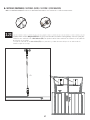
4.1 • If you wish, you can anchor your storage shed to a concrete or wood platform. Tilt the box on its back and drill through the
Floor at the points shown using an 8 mm (5/16") drill bit.
• Si besoin, ancrer l’abri de stockage à une plate-forme en béton ou en bois. Incliner la boîte sur son dossier, et percer le
plancher aux points indiqués à l’aide d’une mèche de 8 mm.
• Si es necesario, anclar el cobertizo de almacenamiento a una plataforma de concreto o madera. Inclinar la caja en su
respaldo, y taladrar a través del piso a las ubicaciones indicadas usando una broca de 8 mm.
http://go.Lifetime.com/60341-section4
• If you have trouble with this section, follow the code below to view a video on how to assemble this section.
• Si vous avez des problèmes avec cette section, suivez le code en bas pour voir un vidéo sur l’assemblage de cette section.
• Si tiene problemas con esta sección, siga el código debajo para ver un video sobre el ensamble de esta sección.

50
TOOLS & HARDWARE REQUIRED / OUTILS ET QUINCAILLERIE REQUIS / INSTRUMENTAL Y HERRAJE REQUERIDOS
X SECTION 4 (CONTINUED) / SECTION 4 (SUITE) / SECCIÓN 4 (CONTINUACIÓN)
(x4)
(x4)
(x4)
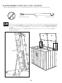
4.2 • Set the box upright and put it in place on the platform. If you’re using a concrete platform, use a hammer drill and a
5/16" (≈8 mm) masonry bit to drill through the holes and into the concrete. Then, insert 3/8" x 2" (≈10 mm x ≈5 cm)
concrete screws through 3/8" (≈10 mm) fender washers and screw them into the platform until fl ush with the fl oor. Do
not overtighten. This hardware may be purchased at your local hardware store. If you’re using a wood platform, use an electric drill
and a 5/16" (≈8 mm) drill bit to drill through the holes and into the wood. Then, insert 3/8" x 2" (≈10 mm x ≈5 cm) lag
screws through 3/8" (≈10 mm) fender washers, and screw them into the wood until fl ush with the fl oor. Do not overtighten.
This hardware may be purchased at your local hardware store.
• Poser la boîte vertical, et mettre-la en place sur la plate-forme. Pour une plate-forme en béton, utiliser un perceuse
à percussion et un foret à maçonnerie de 5/16 po (≈8 mm) pour percer à travers les trous et dans le béton. Ensuite,
insérer les vis à béton de 3/8 po x 2 po (≈10 mm x ≈5 cm) à travers les rondelles de protection de 3/8 po (≈10 mm) et
visser-les à travers les trous et dans le béton jusqu’à ce que les tire-fonds soient à ras du plancher. Ne pas trop serrer. Se
trouvent ces accessoires à la quincaillerie de coin. Pour une plate-forme en bois, utiliser un perceuse électrique et un foret
à bois de 5/16 po (≈8 mm) pour percer à travers les trous et dans le bois jusqu’à ce que les tire-fonds soient à ras du
plancher. Ensuite, insérer les tire-fonds de 3/8 po x 2 po (≈10 mm x ≈5 cm) à travers des rondelles de protection de
3/8 po (≈10 mm), et visser-les dans le bois jusqu’à ce qu’ils soient au ras du plancher. Ne pas trop serrer. Se trouvent ces
accessoires dans une quincaillerie.
• Colocar la caja vertical, y póngalo en su lugar en la plataforma. Para una plataforma hecho de concreto, usar un
martillo perforador y una broca para mampostería de 5/16 in (≈8 mm) para taladrar el concreto. Entonces, insertar los
tornillos para concreto de 3/8 in x 2 in (≈10 mm x ≈5 cm) a través de las rondanas de protección de 3/8 in (≈10 mm) y
atornillarlos en la plataforma hasta que estén a ras del piso. No apretar demasiado. Se puede comprar este herraje en la ferretería
local. Para una plataforma hecho de madera, usar un taladro eléctrico y una broca de 5/16 in (≈8 mm) para taladrar a
través de los agujeros y dentro la madera. Entonces, insertar los tornillos de cabeza cuadrada de 3/8 in x 2 in (≈10 mm x
≈5 cm) a través de las rondanas de protección de 3/8 in (≈10 mm), y atornillarlos en la plataforma hasta que estén a ras
del piso. No apretar demasiado. Se puede comprar este herraje en la ferretería local.
or / ou / o and / et / y
9/16 in/po (≈ 14 mm)
5/16 in/po (≈8 mm)
5/16 in/po (≈8 mm)

51
Congratulations on your Lifetime® product purchase. By following the instructions below, your new Lifetime product should provide you with years of service and enjoyment.
The polyethylene panels are stain and solvent resistant. Most stains can be removed using a mild soap and a soft-bristled
brush. Abrasive cleaning materials may scratch the plastic and are not recommended. Repair scratches or rust spots on the
metal by sanding the a ected area lightly; using a rust preventative spray primer; and fi nally, spraying with a high-gloss spray
enamel paint. Avoid placing a direct heat source on or near surfaces unless using a heat barrier.
Nous vous félicitons d’avoir acheté ce produit Lifetime®. En suivant les instructions ci-dessous, votre nouveau produit Lifetime devrait vous fournir des années de service et de plaisir.
Les murs et les étagères en polyéthylène sont résistants aux taches et solvants de nettoyage. Pour les nettoyer, se servir
d’un savon doux et d’une brosse douce. Les produits abrasifs de nettoyage risquent d’égratigner le plastique et ne sont pas
recommandés. Pour réparer les égratignures ou taches de rouille sur le métal, frotter légèrement l’endroit a ecté au papier de
verre, puis passer une couche de produit vaporisant préventif, et, enfi n, vaporiser une peinture émail ultrabrillante. Éviter de
placer une source de chaleur directe sur ou près des surfaces, ou les protéger à l’aide d’une protection contre la chaleur.
CLEANING & CARE
NETTOYAGE ET ENTRETIEN
Felicidades por la compra de su producto Lifetime®. Al seguir las siguientes instrucciones, su nuevo producto Lifetime le brindará años de servicio y satisfacción.
Los paneles de polietileno son resistentes a las manchas y solventes. La mayoría de las manchas puede removerse usando un
jabón suave y un cepillo de cerdas suaves. Los materiales abrasivos para limpieza pueden rayar el plástico y no se recomien-
dan. Reparar rayones o manchas de óxido en el metal, lijando suavemente la parte afectada; usando un aerosol preventivo de
óxido y fi nalmente, rociando con una pintura de esmalte brillante. Evitar poner una fuente de calor directa en o cerca de las
superfi cies sin usar una barrera de calor.
LIMPIEZA Y CUIDADO

52
LIFETIME’S PROMISE TO YOU:
We invite you to read our privacy policy at www.lifetime.com
REGISTER today!
At Lifetime®, we are committed to providing innovative and quality products. While registering, you will have the opportunity to give us your feedback. Your input is valuable to us.
• You can also opt in to receive new product notifi cations or promotions.
• In the unlikely event of a product recall or safety modifi cation, your registration provides the information we need to notify you directly.
• Registration is fast, easy, and completely voluntary.
Maintaining your privacy is our long-standing policy at Lifetime®. And you can rest assured that Lifetime® will not sell or provide your personal data to other third parties, or
allow them to use your personal data for their own purposes.
REGISTER YOUR PRODUCT ONLINE AT WWW.LIFETIME.COM
LA PROMESA DE LIFETIME® PARA USTED:
Lo invitamos a leer nuestra política de privacidad en www.lifetime.com (sólo en inglés)
¡REGISTRARSE hoy mismo!
En Lifetime®, estamos comprometidos a ofrecer productos innovadores y de calidad. Al registrarse, usted tendrá la oportunidad de darnos su retroalimentación. Su información es valiosa para nosotros.
• También puede optar por recibir nuestras notifi caciones o promociones.
• En el caso improbable de que el producto deba ser retirado del mercado o que sufra alguna modifi cación, su registro provee la
información que necesitamos para notifi carle directamente.
• El registro es rápido, fácil y completamente voluntario.
Mantener privacidad es nuestra política permanente en Lifetime®. Y puede estar seguro que Lifetime® no venderá ni dará datos personales a terceros, ni les permitirá usar
datos personales para sus propios fi nes.
REGISTRAR EL PRODUCTO EN LÍNEA EN WWW.LIFETIME.COM
LA PROMESSE DE LIFETIME :
Nous vous invitons à lire notre politique de confi dentialité à www.lifetime.com (en anglais seulement)
ENREGISTRER CE PRODUIT aujourd’hui!
Chez Lifetime®, nous nous engageons à fournir des produits innovateurs de qualité. Lors de votre inscription, vous aurez l’occasion de nous faire parvenir vos commentaires. Votre opinion est importante
pour nous.
• On peut également choisir de recevoir des avis ou des promotions dans le cadre de nouveaux produits.
• Dans l’éventualité improbable d’un rappel ou d’un avis de sécurité, l’inscription fournit les renseignements nécessaires nous
permettant de communiquer avec vous.
• L’inscription est rapide, facile et complètement volontaire.
Conserver votre confi dentialité est notre politique de longue date chez Lifetime®. Vous pouvez donc être rassuré par le fait que Lifetime® ne vendra pas ou ne fournira pas vos
données personnelles à des tiers, et ne leur permettra pas d’utiliser vos données personnelles à leurs propres fi ns.
ENREGISTRER CE PRODUIT EN LIGNE À WWW.LIFETIME.COM

53
THE MANUFACTURER RESERVES THE RIGHT TO MAKE SUBSTITUTIONS TO WARRANTY CLAIMS IF PARTS ARE UNAVAILABLE OR OBSOLETE.
10-YEAR LIMITED FACTORY WARRANTY
Lifetime Lawn and Garden products are warranted to the original purchaser to be free from defects in material or
WORKMANSHIPFORAPERIODOFYEARSFROMTHEDATEOFORIGINALRETAILPURCHASE4HEWORDhDEFECTSvISDElNEDAS
imperfections that impair the use of the product. Defects resulting from misuse, abuse or negligence will void this
warranty. This warranty does not cover defects due to improper installation, alteration or accident. Lifetime recommends
THATNOMODIlCATIONSBEMADETOTHISPRODUCT4HISWARRANTYDOESNOTCOVERDAMAGECAUSEDBYVANDALISMRUSTING
“acts of nature”, natural disasters, normal wear and tear, or any other event beyond the control of the manufacturer.
This warranty is nontransferable and is expressly limited to the repair or replacement of defective products. If the
product is defective within the terms of this warranty, Lifetime Products, Inc. will repair or replace defective parts at
no cost to the purchaser. Shipping charges to and from the factory or distribution center are not covered and are
the responsibility of the purchaser. Labor charges and related expenses for removal, installation or replacement of
the product or its components are not covered under this warranty.
4HISWARRANTYDOESNOTCOVERSCRATCHINGSCUFlNGOROTHERCOSMETICDAMAGEOFTHEPRODUCTTHATMAYRESULTFROM
normal usage. In addition, defects resulting from intentional damage, negligence, or unreasonable use will void this
warranty / are not covered by this warranty.
Liability for incidental or consequential damages is excluded to the extent permitted by law. All merchandise is sold
on this condition, and no representative of the company may waive or change this policy. This product is not intended
for institutional or commercial use; Lifetime Products, Inc. does not assume any liability for such use. Institutional
or commercial use will void the warranty.
This warranty is expressly in lieu of all other warranties, expressed or implied, including warranties of merchantability
ORlTNESSFORUSETOEXTENTPERMITTEDBY&EDERALANDSTATELAW.EITHER,IFETIME0RODUCTS)NCNORANYREPRESENTATIVE
ASSUMESANYOTHERLIABILITYINCONNECTIONWITHTHISPRODUCT4HISWARRANTYGIVESYOUSPECIlCLEGALRIGHTSANDYOUMAY
also have other rights which vary from state to state.
Our goods come with guarantees that cannot be excluded under the Australian Consumer Law. You are entitled to a
replacement or refund for a major failure and for compensation for any other reasonably foreseeable loss or damage.
You are also entitled to have the goods repaired or replaced if the goods fail to be of acceptable quality and the failure
does not amount to a major failure.
ALL WARRANTY CLAIMS MUST BE ACCOMPANIED BY A SALES RECEIPT.
REPORT PRODUCT DEFECTS IN WRITING TO:
,)&%4)-%02/$5#43).#
PO Box 160010
&REEPORT#ENTER"LDG$
#LEARlELD54
&ORONLINEWARRANTYCLAIMSPLEASEVISITwww.lifetime.com/warranty
7ARRANTY$EPARTMENT
FOR INTERNATIONAL WARRANTY:
!LLWARRANTYCLAIMSMUSTBEACCOMPANIEDBYASALESRECEIPT2EPORTPRODUCTDEFECTSINWRITINGTOYOURREGIONALSALES
support representative. Please include your dated sales receipt and photographs of damaged parts.
4O)DENTIFYTHEREPRESENTATIVEFORYOURREGIONPLEASEVISITwww.lifetime.com/international

54
LIFETIME® PRODUCTS, INC. RÉSERVE LE DROIT DE FAIRE DES SUBSTITUTIONS EN CAS DE RECOURS EN GARANTIE SI LES PIÈCES NE SONT PAS DISPONIBLES OU SONT
OBSOLÈTES.
GARANTIE DE FABRICATION LIMITÉE DE 10 ANS
,ACHETEURDORIGINEDESPRODUITSPOURPELOUSESETJARDINSDE,IFETIMEB¼N¼lCIEDUNEGARANTIECONTRETOUTED¼FECTUOSIT¼
de matériel et de fabrication pour une période de 10 ans à compter de la date d’achat. On entend par « défaut »
une imperfection qui nuit à l’utilisation du produit. Tout défaut découlant d’une mauvaise utilisation, d’un abus ou
d’une négligence a pour effet d’annuler cette garantie. Cette garantie ne couvre pas les défauts attribuables à une
INSTALLATIONINAD¼QUATEUNEALT¼RATIONOUUNACCIDENT,IFETIMERECOMMANDEDENEPASAPPORTERDEMODIlCATIONS
à ce produit. Cette garantie ne couvre pas les dommages causés par le vandalisme, la corrosion par la rouille, les
cas de « force majeure », les catastrophes naturelles, la détérioration et l’usure normales et tout autre événement
indépendant de la volonté du fabricant.
Cette garantie n’est pas transférable et se limite expressément à la réparation ou au remplacement d’un produit
défectueux. Si le produit est défectueux au sens de cette garantie, Lifetime Products, Inc. réparera ou remplacera
les pièces défectueuses sans frais pour l’acheteur. Les frais d’expédition en partance ou en provenance de l’usine
OUDUCENTREDEDISTRIBUTIONNESONTPASCOUVERTSETINCOMBENT¸LACHETEUR,ESCOËTSRELATIFS¸LAMAINDUVRE
et les autres frais liés au retrait, à l’installation ou au remplacement du produit ou de ses composants ne sont pas
couverts par cette garantie.
Cette garantie ne couvre pas les rayures, les égratignures ou autres dommages esthétiques du produit découlant d’un
usage normal. De plus, tout défaut découlant d’un dommage volontaire, de négligence ou d’un usage déraisonnable
annule cette garantie et n’est pas couvert par cette garantie.
Dans la mesure permise par la loi, la société n’est pas responsable des dommages indirects ou accessoires. Toute
marchandise est vendue à cette condition et aucun représentant de la société ne peut renoncer à l’application de cette
POLITIQUEOULAMODIlER#EPRODUITNESTPASDESTIN¼¸DESlNSINSTITUTIONNELLESOUCOMMERCIALES,IFETIME0RODUCTS
Inc. n’assume aucune responsabilité à cet égard. Toute utilisation institutionnelle ou commerciale annule la garantie.
La présente garantie remplace expressément toute autre garantie, expresse ou implicite, y compris les garanties de
qualité marchande ou d’adaptation à un usage particulier dans la mesure permise par les lois du pays ou de l’État.
.I,IFETIME0RODUCTS)NCNIAUCUNDESESREPR¼SENTANTSNASSUMENTUNEQUELCONQUERESPONSABILIT¼ENLIENAVEC
ce produit. Cette garantie vous donne des droits juridiques précis et vous pourriez également avoir d’autres droits
selon l’État ou la province.
La garantie qui accompagne nos produits ne peut être exclue en vertu de la loi sur la protection du consommateur
de l’Australie. Le client a droit à un remplacement ou à un remboursement en cas de bris majeur et pour toute
autre perte ou dommage raisonnablement prévisible. Le client a aussi droit à ce que les produits soient réparés ou
REMPLAC¼SSIUNBRISSURVIENTETRENDLAQUALIT¼INACCEPTABLESANSPOURAUTANT½TREQUALIlABLEDEBRISMAJEUR
TOUTE RÉCLAMATION EN VERTU DE LA GARANTIE DOIT ÊTRE ACCOMPAGNÉE D’UN REÇU DE VENTE.
SIGNALEMENT ÉCRIT DE TOUT PRODUIT DÉFECTUEUX:
,)&%4)-%02/$5#43).#
PO Box 160010
&REEPORT#ENTER"LDG$
#LEARlELD54
0OUREFFECTUERENLIGNEUNER¼CLAMATIONSOUSGARANTIECONSULTEZCETTEADRESSEwww.lifetime.com/warranty
3ERVICEDELAGARANTIE
GARANTIE INTERNATIONALE:
Toute réclamation en vertu de la garantie doit être accompagnée d’un reçu de vente. Veuillez signaler par écrit tout produit
défectueux au représentant du soutien aux ventes de votre région Veuillez inclure le reçu de vente daté ainsi que des
photographies des pièces endommagées.
0OURCONNAÁTRELEREPR¼SENTANTDEVOTRER¼GIONVEUILLEZCONSULTERLEwww.lifetime.com/international

55
EL FABRICANTE SE RESERVA EL DERECHO DE HACER SUSTITUCIONES EN LOS ELEMENTOS REEMPLAZADOS BAJO GARANTÍA SI LAS PIEZAS
NO ESTÁN DISPONIBLES O SON OBSOLETAS.
GARANTÍA DE FÁBRICA LIMITADA POR 10 AÑOS
El comprador original recibe una garantía de que los productos de césped y jardín de Lifetime están libres de defectos
de material o mano de obra durante un período de 10 años a partir de la fecha de compra original al por menor.
La palabra “defectos” se defi ne como imperfección que imposibilita el uso del producto. Los defectos ocasionados
por el mal uso, el abuso o la negligencia anularán esta garantía. Esta garantía no cubre los defectos debidos a una
instalación incorrecta, una alteración o un accidente. Lifetime recomienda que no se realicen modifi caciones en este
producto. Esta garantía no cubre los daños causados por vandalismo, oxidación, “actos de la naturaleza”, desastres
naturales, desgaste normal o cualquier otro evento fuera del control del fabricante.
Esta garantía no es transferible y se limita expresamente a la reparación o reemplazo de productos defectuosos. Si el
producto resulta defectuoso dentro de los términos de esta garantía, Lifetime Products, Inc. reparará o reemplazará
las piezas defectuosas sin costo alguno para el comprador. Los gastos de envío hacia y desde la fábrica o el centro
de distribución no están cubiertos y son la responsabilidad del comprador. La mano de obra y los gastos relacionados
por la remoción, la instalación o la sustitución del producto o sus componentes no están cubiertos por esta garantía.
Esta garantía no cubre los rayones, los raspones ni otros daños superfi ciales del producto que pueden resultar del
uso normal. Asimismo, los defectos resultantes de daños intencionales, negligencia o uso indebido anularán o no
están cubiertos por esta garantía.
Se excluye la responsabilidad por daños imprevistos o derivados en la medida en que lo permita la ley. Toda la
mercancía se vende bajo estas condiciones y ningún representante de la empresa puede renunciar a ni cambiar
esta política. Este producto no está destinado para uso institucional o comercial; Lifetime Products, Inc. no asume
ninguna responsabilidad por dicho uso. El uso institucional o comercial anulará la garantía.
Esta garantía sustituye expresamente cualquier otra garantía, expresa o implícita, incluidas las garantías de
comercialización o idoneidad para su uso en la medida permitida por la ley federal y estatal. Ni Lifetime Products,
Inc., ni ningún representante asume ninguna otra responsabilidad en relación con este producto. Esta garantía le
otorga derechos legales específi cos y usted también puede tener otros derechos que varían de un estado a otro.
Nuestros productos vienen con garantías que no se pueden excluir bajo la Ley Australiana del Consumidor. Usted
tiene derecho a recibir un reemplazo o reembolso por un fallo grave y compensación por cualquier otra pérdida o
daño razonablemente previsible. También tiene derecho a la reparación o el reemplazo de los bienes si los bienes
no son de calidad aceptable y el fallo no supone un fallo grave.
TODOS LOS RECLAMOS DE GARANTÍA DEBEN ESTAR ACOMPAÑADOS POR UN RECIBO DE COMPRA.
REPORTE LOS DEFECTOS DEL PRODUCTO POR ESCRITO A:
LIFETIME PRODUCTS, INC.,
PO Box 160010
Freeport Center, Bldg. D-12
Clearfi eld, UT 84016-0010
Para realizar reclamos de garantía por internet, visite: www.lifetime.com/warranty.
Departamento de Garantías: (800) 225-3865
PARA LA GARANTÍA INTERNACIONAL:
Todos los reclamos de garantía deben estar acompañados por un recibo de compra. Reporte los defectos del producto por
escrito a su representante regional de apoyo de ventas. Por favor, incluya su recibo de compra con la fecha y fotografías de
las piezas dañadas.
Para identifi car al representante de su región, por favor visite: www.lifetime.com/international
GARANTIA NO VÁLIDA EN MÉXICO

56
Or call 1-800-424-3865
To purchase accessories or other Lifetime® products, visit us at:
www.lifetime.com
O marcar al 1-800-424-3865
Para comprar accesorios u otros productos Lifetime® EUA, visitarnos en:
www.lifetime.com
ENHANCE YOUR LIFETIME® PURCHASE BY ADDING ACCESSORIES OR OTHER GREAT PRODUCTS
MEJORAR SU COMPRA LIFETIME® Y AÑADIR ACCESORIOS U OTROS PRODUCTOS EXCELENTES
Ou composer le 1-800-424-3865
Pour acheter des accessoires ou d’autres produits Lifetime®, nous rendre visite à :
www.lifetime.com
AMÉLIORER VOTRE ACHAT LIFETIME® EN AJOUTANT DES ACCESSOIRES OU D’AUTRES PRODUITS
1223955_B 4/13/2023
-
 1
1
-
 2
2
-
 3
3
-
 4
4
-
 5
5
-
 6
6
-
 7
7
-
 8
8
-
 9
9
-
 10
10
-
 11
11
-
 12
12
-
 13
13
-
 14
14
-
 15
15
-
 16
16
-
 17
17
-
 18
18
-
 19
19
-
 20
20
-
 21
21
-
 22
22
-
 23
23
-
 24
24
-
 25
25
-
 26
26
-
 27
27
-
 28
28
-
 29
29
-
 30
30
-
 31
31
-
 32
32
-
 33
33
-
 34
34
-
 35
35
-
 36
36
-
 37
37
-
 38
38
-
 39
39
-
 40
40
-
 41
41
-
 42
42
-
 43
43
-
 44
44
-
 45
45
-
 46
46
-
 47
47
-
 48
48
-
 49
49
-
 50
50
-
 51
51
-
 52
52
-
 53
53
-
 54
54
-
 55
55
-
 56
56


en otros idiomas
- français: Lifetime 60341 Le manuel du propriétaire
- English: Lifetime 60341 Owner's manual