
46000 SERIES CONVERTIBLE
RANGE HOOD
INTENDEDFORDOMESTIC
COOKINGONLY.A,
BROAN
CAMPANA EXTRACTORA
CONVERTIBLE DE LA SERIE 46000
IMPORTANT
For Non-ducted Installation:
a) Purchase non-ducted fitter separately.
b) Remove and discard damper/duct connector and lou-
ver cover (See Step 2) in "Prepare the Hood','Page 2.
c) Fotlow alI steps except steps inside dotted fines.
For Ducted Installation:
EFo,-TTow7 I
steps, including steps inside dotted lines, j
WARNING
TO REDUCE THE RISK OF FIRE, ELECTRIC SHOCK,
OR INJURY TO PERSONS, OBSERVE THE FOLLOW-
ING:
1. Use this unit only in the manner intended by the manu-
facturer. If you have questions, contact the manufac-
turer at the address or telephone number listed in
the warranty.
2. Before servicing or cleaning unit, switch power off at
service panel and lock the service disconnecting
means to prevent power from being switched on ac-
cidentally. When the service disconnecting means
cannot be locked, securely fasten a prominent warn-
ing device, such as a tag, to the service panel.
3. Installation work and electrical wiring must be done
by a qualified person(s) in accordance with alt appli-
cable codes and standards, including fire-rated con-
struction codes and standards.
4. Sufficient airis needed for proper combustion and ex-
hausting of gases through the flue (chimney) of fueI
burning equipment to prevent backdrafting. Follow the
heating equipment manufacturer's guideline and safety
standards such as those published by the National Fire
Protection Association (NFPA), and the American So-
ciety for Heating, Refrigeration and Air Conditioning
Engineers (ASHRAE), and the local code authorities.
5. When cutting or drilling into wattor ceiling, do not dam-
age electrical wiring and other hidden utilities.
6. Ducted fans must always be vented to the outdoors.
7. Do not use this unit with an additonal speed control
device.
8. To reduce the risk of fire, use only metal ductwork.
9. Use with approved cord-connection kit only.
10 This unit must be grounded.
TO REDUCE THE RISK OF A RANGE TOP GREASE
FIRE:
1. Never leave surface units unattended at high settings.
Believers cause smoking and greasy spitlovers that
may ignite. Heat oils slowly on low or medium set-
tings.
2. Always turn hood ON when cooking at high heat or
when cooking flaming foods.
3. Clean ventilating fans frequently. Grease should not
be allowed to accumulate on fan or fitter.
4. Use proper pan size. Always use cookware appropri-
ate for the size of the surface element.
TO REDUCE THE RISK OF INJURY TO PERSONS IN
THE EVENT OF A RANGE TOP GREASE FIRE, OB-
SERVE THE FOLLOWING:*
1. SMOTHER FLAMES with a close-fitting rid, cookie
sheet, or metal tray, then turn offthe burner. BE CARE-
FUL TO PREVENT BURNS. Ifthe flames do not go out
immediately, EVACUATE AND CALL THE FIRE DE-
PARTMENT.
2. NEVER PICK UP A FLAMING PAN - You may be
burned.
3. DO NOT USE WATER, including wet dishcloths or
towels - a violent steam explosion wilt result.
4. Use an extinguisher ONLY if:
A. You know you have a Class ABC extinguisher and
you already know how to operate it.
B. The fire is small and contained in the area where it
started.
C. The fire department is being called.
D. You can fight the fire with your back to an exit.
* Based on "Kitchen Fire Safety Tips" published by
NFPA.
INSTALLER:LeaveThisManualWithThe
Homeowner.HOMEOWNER:UseandCare
InformationonPage5.
INSTALADOR:Dejeestemanualconeldueho
dela casa.DUEN0DELACASA:Informacion
acercadelusoy loscuidadosen laPagina5.
PREVISTOPARACOClNAR
DOMI STICOSOLAMENTE.
IMPORTANTE
Para instalacibn sin ducto:
a) Compra el filtro sin conductos separado.
b) Quite y descarte el conector del regulador/ducto y la
tapa de la rejilla (Vease paso 2) en la Pa.gina 2 titulada
"Prepare el extractor."
c) Siga todos los pasos excepto de los pasos dentro las
gneas suspensivas.
Para instalacibn con ducto:
I'-sTga todos los pasos incluyendo los pasos dentro de1
/las Ifneas suspensivas, j
PRECAUCION
PARA REDUCIR EL RIESGO DE INCENDIO, CHOQUE
ELECTRICO, O LESION A PERSONAS, PROCURE LO
SIGUIENTE:
1. Utiflce esta unidad s61o en la manera prescrita por et
fabricante. Si tiene usted alguna pregunta, comunfquese con
et fabricante a ta direcci6n o et tetefono indicados en ta
garantfa.
2. Antes de timpiar o de poner enservicio la unidad, apague et
interruptor en el panel de servicio, y asegure eI panel de
servicio para evitar que se encienda accidentatmente.
Cuando el dispositivo para desconectar etservicio electrico
no puede ser cerrado con atgt_n tipo de traba, sujete
fuertemente at panel de servicio, una etiqueta de advertencia
prominente.
3. Todo trabajo de instatacion y cabteado etectrico debe ser
realizado por personal catificado y de acuerdo con todos los
c6digos y normas pertinentes, incluyendo los c6digos y
normas retacionados con construcci6n clasificada para
incendio.
4. Aire suficiente es necesario para facilitar la combusti6n
adecuada y la saiida apropiada de gases por la chimenea
de la unidad ypara evitar corrientes de aire invertidas. Siga
tasinstrucciones y medidas de seguridad del fabricante del
equipo y de tas sociedades profesionates de equipos de
catentadores y los reglamentos de seguridad locales.
5. A cortar o perforar la pared o et techo, no da_e el cableado
electrico u otros servicios pLibticos ocuttos a tavista.
6. Los abanicos con ducto debera.n siempre tener una salida
hacia eI exterior.
7. No utilice esta unidad en conjunto con cuatquier dispositivo
de control de velocidad adicional.
8. Para reducir el riesgo deincendio, use s61oductos de metal.
9. Uso con el kit aprobado della conexi6n de la cuerda
sotamente.
10. Esta unidad se debe instalar con tierra efectiva.
PARA REDUCIR EL RIESGO DE INCENDIO DEBIDO AGRASA
ACUMULADA EN LAS HORNILLAS:
1. Nunca deje sin atender tas unidades de superficie cuando
tengan ajustes altos. Los reboses pueden provocar humo y
derrames grasosos que se pueden incendiar. Cafiente
Ientamente et aceite en unajuste bajo o medio.
2. Siempre ENCIENDA la campana cuando cocine con atta
temperatura o cuando cocine atimentos que se puedan
incendiar.
3. Limpie con frecuencia tosventiladores. No debe permitir que
Iagrasa se acumule en etventilador ni en elfiltro.
4. Utilice un sarten de tamaSo adecuado. Siempre utilice et
utensilio adecuado at tamaSo det elemento de superficie.
PARA REDUCIR EL RIESGO DE LESION A PERSONAS
RESULTADO DE UN INCENDIO DEBIDO A GRASA
ACUMULADA EN LAS HORNILLAS, PROCURE LO
SIGUIENTE:*
1. AHOGUE LAS LLAMAS con una tapa ajustada o charota de
metal, despues apague ta hornilta. TENGA CUIDADO A FIN
DE EVITAR QUEMADURAS. Si las llamas no se apagan de
inmediato, EVACUE YAVlSE A LOS BOMBEROS.
2. NO LEVANTE NUNCA UNA SARTEN QUE ESTE EN
LLAMAS - Usted se podra quemar.
3. NO UTILICE AGUA, inctuyendo toaltas de cocina mojadas -
puede resultar una exptosi6n de vapor viotenta.
4. Utilice un extinguidor SOLAMENTE si:
A. Usted sabe que tiene un extinguidor de ctase
ABC y Io sabe utitizar.
B. Et incendio es peque_o y contenido dentro del
a.rea donde se inici6.
C. Los bomberos han sido avisados.
D. Usted puede combatir el incendio con una salida a
su espatda.
* Basado en tas recomendaciones para "Seguridad en ta
Cocina" pubticadas pot la NFPA de los EEUU.

CAUTION A.
1. For general ventilating use only. Do not use to exhaust
hazardous or explosive materials and vapors.
2. To avoid motor bearing damage and noisy and/
or unbalanced impellers, keep drywall spray,
construction dust, etc. off power unit.
3. Your hood motor has a thermal overload which will
automatically shut off the motor if it becomes
overheated. The motor will restart when it cools
down. If the motor continues to shut off and restart,
have the hood serviced.
4. For bestcapture of cooking impurities, your range hood
should be mounted 18-24" above the cooking surface.
5. Please read specification label on product for further
information and requirements.
TOOLS AND
MATERIALS REQUIRED
TOOLS
3 Drill, electric or ratchet drive
3 1-1/4" Spade bit
3 Common head and phillips head screwdriver
3 Pliers
3 Tape measure or ruler and pencil
FFor Ducted Installations ONLY: |
I 3 Saber saw or drywall saw I
LJ Metal snips j
MATERIALS
3 Electrical wiring and supplies of type to comply
with local codes
Fj Roof or wall cap |
I 3 Roof cement or caulk I
Duct and duct tape j
For Installation on Kitchen Cabinets with Recessed
Bottoms Only:
3 Two 1" x 2" x 12" (approximate length) wood strips
(purchase locally)
3 Four 1-1/4" long flat head wood screws (purchase
locally) to fasten strips to cabinet bottom
PLANNING DUCTWORK
INSTALLATION
Begin planning ductwork by deciding where the duct
will run between the range hood and the outside. For
best performance, use the shortest possible duct run
and a minimum number of elbows. There are several
choices shown - FIGS. 1A - 1E.
In more complex ducting situations, a 3-1/4" rectan-
gular ducting range hood can be converted to a round
duct by means of a transition.
FIG. 1A. Ducting directly through the wall (for range
hoods mounted on an exterior wall). Shown are two
ways to duct through an outside wall. If a wall cap is
used directly off the back of the hood, special care
must be taken to make sure that the damper in the
damper/duct connector on the hood and damper in
the wall cap do not interfere with each other when the
hood is operating. This could result in either inad-
equate air delivery or back drafts. If this condition does
exist, remove the hood damper flap. Sometimes when
using a wall cap it is easier to duct vertically and then
use an elbow as shown in FIG. lB.
FIG. lC. Ducting straight up through the roof using
3-1/4" x 10" rectangular duct. (For single story in-
stallations.)
FIG. 1D. Ducting between the ceiling joists (for multi-
story installations) or through the soffit space above
the cabinets (where the soffit connects to an outside
wall).
FIG. 1E. Straight up through the roof using 6" round
duct (for single-story installations).
FIG. 1A
WALL CAP 639 OR 649
CASQUETE DE PARED 639 O 649
WALLCAP639OR649
FIG. 1B CASQUETEDEPARED
6390 649
_3-1/4' x 10" DUCT401
I 0"40
ROOFCAP634OR644
FiG.lc I. _7 g gE 4 g 44
I I 3-1/4"x 10"DUCT401
ii "'DUOTOTE401
@
FIG. 1D
ADJUSTABLE ELBOW 419
CODO AJUSTABLE 419
WALL CAP 641
CASQUETE DE
PARED 641
6" ROUND DUCT 406
DUCTO REDONDO DE
6" 406
3-1/4" x 10" TO 6"
:{OUND DUCT
TRANSITION 411
TRANSICION DE
3-1/4" x 10" A
UN DUCTO
REDONDO
DE 6"411
FIG. 1E ROOFCAP634OR644
CASQUETEDETECHO634O 644
PRECAUCION
1. Solamente para uso general de ventilaci6n. No utilice para
descargar materiales o vapores riesgosos o explosivos.
2. Para evitar daSos al motor y evitar que las navajas del
abanico emitan mucho ruido o esten fuera de balance,
mantenga el motor libre de pelusa, polvo, etc.
3. El motor de su extractor tiene dispositivo de sobrecarga
termica, al cual automaticamente apagara el motor si
se sobrecalienta. El motor funcionardt de nuevo cuando
se enfrfe. Si el motor continua apagandose y arrancando,
hagalo componer.
4. Para obtener mejores resultados en la captura de los
vapores de la estufa, el extractor debe montarse a entre
18 y 24 pig. sobre las hornillas de la estufa.
5. Por favor lea la etiqueta con las especificaciones del
equipo para otros requisitos y mayor informacion.
HERRAMIENTAS Y
MATERIALES QUE SE
REQUIEREN
HERRAMIENTAS
3 Taladro, electrico o trinquete
3 Broca tipo pala de 1-1/4"
3 Destornillador de ranura o tipo phillips
3 Pinzas o tenazas
3 Medidor de cinta o regla y lapiz
Fp'_rra instalaciones con ducto SOLAMENTE: 1
I 3 Sierra tipo sable o sierra para tabiques I
Alicate para cortar j
MATERIALES
3 Suministros y alambre electrico del tipo que cumplen
con los codigos locales
F_ Casquete de techo o pared 1
I 3 Cemento o pega de techa o material de calafatear I
I
o rellenar
I
1 2 Ductos y cinta aislante para ductos j
Para instalaci6n en gabinetes de cocina con la parte infe-
rior ahuecada solamente:
3 Dos tiras de madera 1" x 2" x 12" (largo aproximado)
(compreselas Iocalmente)
3 Cuatro tornillos para madera de cabeza plana de 1-1/4"
de largo (c6mpreselas Iocalmente) para sujetar las tiras
de madera a la parte inferior de gabinete
PLANIFICANDO LA
INSTALACION DE LOS
DUCTOS
Comience el trabajo de los ductos decidiendo el camino
que el ducto tomara entre el extractor y la parte exterior
de la casa. Para mejor rendimiento, use el camino de ducto
ma.s corto posible y un mfnimo de codos. Se muestran
varias elecciones - FIGS. 1A - 1E.
En situaciones de paso del ducto m_ts complejas, el ex-
tractor con conexi6n para ducto rectangular puede
convertirse en conexi6n redonda usando una transici6n.
FIG. 1A. Pasando el ducto directamente a traves de la
pared (para los extractores que estan instalados en una
pared exterior). Se muestran dos maneras de pasar el
ducto a traves de la pared exterior. Si se usa un casquete
de pared directamente en la parte de atrfits del extractor
hay que asegurarse que el regulador en el conector entre
ducto y regulador en el extractor, y el regulador en el
casquete de pared no interfieran el uric con el otro cuando
el extractor este operando. Esto podrfa resultar en paso
de aire inadecuado o corrientes invertidas. Siesta
condicion existe, quite la hoja instalada en el regulador
del extractor. A veces cuando se usa un casquete de pared
es ma.s facil pasar el ducto verticalmente y usar un codo
como se muestra en FIG. lB.
FIG. lC. Haciendo un ducto directamente al techo usando
un ducto rectangular de 3-1/4" x 10" (para instalaciones
en un piso solamente).
FIG. 1D. Instalando un ducto entre las vigas del techo
(para instalaciones en mas de un piso) o a traves del
espacio de sofito arriba de los gabinetes (cuando el sofito
esta conectado a una pared exterior).
FIG. 1E. Directamente hacia el techo usando ducto
redondo de 6" (para instalaciones de un piso).

PREPARING THE
RANGE HOOD
• Unpack hood and check contents• You should
receive:
1 - Aluminum Filter
1 - 3-1/4" x 10" Damper/Duct Connector (mounted
inside of hood for shipping only) (Save screws for
mounting•)
1 - 7" Round Duct Plate (mounted on top of hood)
(not shown) (Save screws for mounting•)
2. Remove 7" round duct plate from top of hood. Set
duct plate aside - with mounting screws•
3. Remove wiring box cover. Under cover find:
1 - Plastic Bag containing loose mounting hardware
4. For non-ducted installation, remove louver cover
from front of hood. (FIG. 3)
5. Remove either top or rear electrical knockout de-
pending upon whether wiring will enter hood from
wall or cabinet• (FIG. 4)
rD_T_,_T_ELA-+To_ONLY
NOTE I
I Louver cover must be installed as shown in
Figure 3 to function in ducted mode.
6. Remove appropriate duct knockout on hood by
inserting screwdriver into edge of knockout and
breaking tabs holding knockout to hood. You may
have to tap screwdriver with hammer to break tabs.
Peel knockout back with pliers• (FIG. 5)
NOTE II
TAKE CARE WHEN REMOVING THE 31A'' I.
X 10" VERTICAL DUCT KNOCKOUT. DO
I',
NOT DAMAGE THE 7" ROUND DUCT
KNOCKOUT.
i
I 7. Fitdamper/ductconnectoroveropening and secure
in place with black sheet metal screws. (FIG. 6)
Hinge pins and damper/duct connector should be
toward top of hood for ducting through wall or to-
ward back of hood for ducting through cabinet
above hood. Seal joint between damper/duct con-
nector and hood with duct tape.
8. 7" round ducted discharge only: Re-install 7"
round duct plate removed in Step #2 under"PRE-
PARING THE RANGE HOOD" section, For best
performance, line up the 7" round duct plate
with the 7" round opening on hood. Mount duct
plate to hood with 2 screws from duct plate and 2
1
screws from 3 ¼"x 10" damper. Install a 7" round
damper (purchase separately). Damper flap must
open freely in direction of air flow (away from range
L hood), d
OMIT STEP 9 if range hood will be installed under
cabinets with flush bottom.
9. (For installation on recessed bottom cabinets
only) Attach a wood filler strip at each side of
recessed area under cabinet. (Use two 1" x 2"
strips cut to length.) If recess is more than 1" use
thicker strips. Attach strips with 1-1/4" screws
about 3" from each end. See FIG. 7.
10. Measure and mark the following (FIGS. 7 & 8):
a) Electrical line opening
E b) Duct opening ]
11. Drill four pilot holes in corners of marked duct
opening as shown and cut opening with saber
saw or keyhole saw.
12. Use 1-1/4" drill bit to drill opening for electrical
connection in wall or cabinet•
13. Hold hood up against cabinet bottom and trace
keyhole slots onto cabinet bottom of filler strips•
14. Screw the four supplied 7/8" wood screws for
mounting the hood into the exact center of the
narrow end of the keyhole slots marked under-
neath the cabinet• Allow 3/8 = of the screws to
project, so the hood can be fitted into place•
\
;F-/-- 0EHOESOOE_--_
OONECTORALREGULADOR'DUCTO
FIG. 4
°\
/
/
I'
/
FIG. 5 " .
®® ]
FIG. 7
C7
_z
\
_ .............................................CUT STRIP .................................................................._li
\_ ..f_ co RTEuELASAT'RASPARA "-_/
.%"- '-DU OP GS""*'
ALB_I_ToUT_)APARA 01%Eb'RELNITNEIC AX\
. u W, HO, \\ -
RANGE HOOD
ANCHO DEL ELECTRICAL WIRING OPENING
EXTRACTOR ABERTURA PARA EL
CABLEADO ELECTRICO
PREPARANDO EL
EXTRACTOR
1. Desempaque el extractor y revise el contenido de la caja.
Usted debe de encontrar:
1 -Filtro de aluminio
1 -Conector de ducto!regulador de 3-1/4" x 10"
(montado dentro del extractor para embarque
solamente) (Guarde los tornillos para el montaje.)
1-Placa del conducto redondo de 7" (montado en del ex-
tractor) (no se muestra) (Guarde los tornillos para el
montaje.)
2. Quite la placa del conducto redondo de 7" de la parte
superior de la campana. Col6quela aparte, con los tornil-
los de montaje.
3. Quite la cubierta de la caja de cableado. Bajo la tapa
encontrar_i:
1 -Una bolsa de pl_istico qua contiene herrajes
sueltos para instalaci6n
4. Para instalaciones sin ducto, quite la tapa de la rejillas
de la parte frontal del extractor. (FIG. 3)
5. Quite la tapa de quitar golpeando electrica de arriba o
atras dependiendo en donde entra el cableado al extrac-
tor de la pared o del gabinete. (FIG. 4)
INSTALACION CON DUCTO SOLAMENTE 1
NOTA
i
La cubierta de las rejillas se debe instalar como se I
muestra en la figura 3 para qua funcione con el
1
conducto.
6. Quite la placa de quitar golpeando en el extractor
insertando un destornillador en el filo y rompiendo
las conexiones que Iosostienen al extractor. Es posible
que tenga que golpear el destornillador con un martilo
para romper estas uniones. Pele la tapa de quitar
golpeando hacia atr_is con una tenaza. (FIG. 5)
NOTA
i
TENGA CUIDADO AL QUITAR EL AGUJERO I
CIEGO DEL CONDUCTOVERTICAL DE 8.25 X 25.4 I
CM (3_2" X 10"). NO DANE EL AGUJERO CIEGO I
DEL CONDUCTO REDONDO DE 17.78 CM (7"). 1
i
7. Junte el conector del regulador/ducto sobre la
abertura y sujetelo en su sitio con tornillos negros de
metal para lamina. (FIG. 6)
Los pasadores de bisagra y el conector del regulador/
ducto deben de estar hacia la parte de arriba del ex-
tractor para pasar el ducto a traves de la pared o hacia
la parte de atras del extractor para pasar el ducto a
traves de gabinete encima del extractor. Selle la uni6n
entre el conector reguladoriducto con cinta de ducto.
8. S61o para descargae con conducto redondo de 7":
Vuelva la instalar la placa del conducto redondo de 7"
que quit6 en el paso 2 de la secci6n "PREPARANDO
EL EXTRACTOR." Para obtener un major rendimento,
alinee la placa del conducto redondo de 17.8 cm (7")
con la abertura redonda de 17.8 cm (7") de la
campana. Monte la placa del conducto al lacampana
con does tornillos desde la placa del conducto y con
dos tornillos desde el tiro de 8.3 x 25.4 cm (3W' x
10"). Instale un regulador de tiro redondo de 7" (se
compra por separado). La aleta del regulador se debe
abrir libermente en direcci6n del flujo de aire (an
sentido contrario a la campana la estufa), j
OMITA PASO 9 si el extractor estara instalado debajo de un
gabinete con la parte inferior plana.
9. (Para instalacidn en gabinetes ahuecados solamente)
Sujete una tira de madera a cada lado de la parte infe-
rior ahuecada debajo del gabinete. (Use dos tiras de
madera de 1" x 2" cortadas al largo necesario.) Si el
ahuecamiento es m_is de 1" use tiras m_is gruesas.
Sujete las tiras con tornillos de 1-1/4" a una distancia
de mas o menos 3" del extremo. Vease FIG. 7.
10. Mida y marque Io siguiente (FIG. 7 & 8):
a) Abertura para la linea electrica
E b) Abertura para el ducto ]
11.Perfore cuatro huecos pilotos en las esquinas ya
marcadas de la abertura para el ducto como se muestra
y luego corte un abertura con un serrucho sable oun
serrucho para oerradura.
12. Usese una broca de 1-1/4" para perforar una abertura
para la conexi6n electrica en la pared o gabinete.
13. Sostenga al extractor debajo de la parte inferior del
gabinete y trace las ranuras en forma de hueco de
cerradura en la parte inferior del gabinete donde se
instalar_in las tiras de madera.
14. Atornille cuatro de los tornillos de madera de 7/8" para
montar el extractor en el centro exacto de la parte
estrecha de la ranuras en forma de cerradura que se
marcaron debajo del gabinete. Permita que 3/8" de los
tornillos queden afuera, para qua luego pueda instalarse
al extractor en su sitio.

INSTALLIN G THE
DUCTWORK
NOTE
THESE INSTRUCTIONS WILL FOLLOW THE
PLANS MADE ON PAGE 2. START AT THE EX-
TERIOR AND RUN THE DUCT BACK TO THE
RANGE HOOD.
FOR BEST PERFORMANCE OF YOUR RANGE
HOOD, USE THE SHORTEST POSSIBLE DUCT
RUN AND A MINIMUM NUMBER OF ELBOWS.
NEVER VENT A RANGE HOOD INTO AN AT-
TIC SPACE BECAUSE A BUILDUP OF
GREASE WILL BECOME A FIRE HAZARD.
USE ONLY METAL DUCTWORK (DO NOT USE
PLASTIC DUCT). ASSEMBLE SECURELY SO
THAT IN CASE OF A GREASE FIRE ON THE
RANGE, THE FIRE WILL BE CONTAINED IN-
SIDE METAL DUCT WORK.
IT IS A GOOD PRACTICE TO TAPE ALL DUCT
CONNECTIONS, MAKING THEM BOTH SE-
CURE AND AIR TIGHT.
15. Follow appropriate directions below for type of
duct work you are installing:
WALL CAPS (FIG. 9)
Use a saber saw to cut a hole slightly larger than
duct so duct will line up easily with hood. Install
casing strips on outside walls finished in siding.
Assemble the duct work and tape all joints. Run
duct work back to hood. Fasten wall cap to last
section of duct and nail or screw cap to wall. Seal
all around flange on wall cap with caulking com-
pound. Make sure that enough duct runs into the J
room so that the duct will overlap the damper/duct
iconnector by 3/4" when the hood is installed.
ROOF CAPS
Cut hole in roof slightly larger than duct so duct
will line up easily with hood. Trim shingles around
hole so that they will fit snugly around hood of cap
when cap is installed. Assemble the duct work and
tape all joints. Run the duct work down to hood.
Trim duct parallel to roof pitch, leaving 3/4" of duct
projecting above roof. Seal all around duct with
roof cement.
Install roof cap, inserting back edge of cap under J
shingles. Seal around cap with roof cement and
i
seal all nail heads and shingles which were cut or
lifted.
i
Make sure that enough duct runs into the room so I
that the duct will overlap the damper/duct connec- J
tor by 3/4" when the hood is put into place.
L J
FIG. 8
3-1/4" x 10" DUCT
DUCTO DE 3-1/4" x 10"
FRONTOFCABINET
PARTEFRONTALDEL
GABINETE
L3/8 8,4
HOR,BONTALOOCT,NOAND
WIRING (ThroughWall) _7 2"_
DUCTOSYALAMBRBSPARACONEXION ' " ' CABINETBOTTOM
HORIZONTAL(A travesdela pared) GABINETE
1.1/2"_
VERTICAL DUCTINGAND WIRING
(Through Cabinet Bottom) PAREDTRASBRA
DUCTOS YALAMBRES PARACONEXlON VERTICAL (A
tray,s de la parte inferio_ delgabinete)
7" ROUND DUCT
DUCTO REDONDO DE 7"
- CABINET FRONT / FRENTE BEL GABINETE
FONDO DEL GABINET_.
8" DIA.ACCESS HOLE -_
ORIFIC[OD_EDiAtCESO_ --
WOOD SHIMS t ELECTRICAL ACCESS HOLE
(recessed-bottom cabinets only) (in cabinet bottom)
CUitAS DE MADERA _,. ORIFICIO DE ACCESO PARA
(s61o gabinetes de rondo empotrado) LOS CABLES ELECTRICOS
(en el fondo del gabinete)
FIG. 9
WALL CAP
TAPA DE PARED
1-1/2"
-INSTALAN DO LOS
DUCTOS
"1
NOTESE
ESTAS INSTRUCCIONES SEGUIRAN LOS PLANES
HECHOS EN LA PAGINA 2. COMIENCE EN LA
PARTE EXTERIOR Y TRAIGA EL DUCTO HACIA
EL EXTRACTOR.
PAPA EL MEJOR RENDIMIENTO DE SU EXTRAC-
TOR, USE EL CAMINO MAS CORTO DE DUCTO Y
UN MtNIMO DE CODOS.
NUNCA DESCARGUE EL AIRE DEL EXTRACTOR
EN EL ESPACIO DE LA BUHARDILLA PORQUE
UNAACUMULACI(_N DE GRASA PODRtA CAUSAR
UN INCENDIO.
USE SOLAMENTE DUCTOS DE METAL (NO USE
DUCTOS DE PLASTICO). ENSAMBLELOS BtEN DE
MANERA QUE EN CASO DE QUE HUBIESE UN
INCENDIO CAUSADO POR GRASA, EL INCENDIO
SE QUEDARA CONTENIDO DENTRO DE LOS
DUCTOS DE METAL.
ES UNA BUENA PRACTICA EL PONER CINTA EN
TODAS LAS CONEXtONES DEL DUCTO
HACIENDOLOS NO SOLAMENTE SEGUROS SI NO
TAMBtI_N A PRUEBA DE ESCAPE DE AIRE.
15. Siga las direcciones apropiadas abajo para el tipo
de ductos que este instalando:
CASQUETES DE PARED (FIG. 9)
Use una sierra sable para cortar un hueco ligeramente
ma.s grande que el dia.metro del ducto de manera que
el ducto se alinee mas facilmente con el extractor.
Instale tiras de sosten en las paredes exteriores que
esten acabadas con superficie exterior de madera,
aluminio o vinilo. Ensamble los ductos y ponga cinta
en todas las uniones. Traiga los ductos de afuera hacia
al extractor. Sujete el casquete de pared a la L_ltima
seccion de ducto y clave el casquete a la pared. Selle
alrededor de la ceja del casquete con un compuesto
para rellenar. AsegQrese que hay suficiente ducto que
entra a la cocina de manera que el ducto sobrepasara
y entrarfit dentro el conector de regulador/ducto por Io
menos por 3/4" cuando este el ducto instalado.
CASQUETES DEL TECHO
Corte un hueco en el techo mas grande que el diametro
del ducto de manera que el ducto se alineara mas
fa.cilmente con el extractor. Recorte el tejado (tablillas
de tejado) alrededor de hueco de manera que quepan
apretadamente alrededor de casquete cuando este
instalado. Ensamble los ductos y ponga cinta aislante
en todas las uniones. Traiga el ducto hacia abajo, al
extractor. Recorte el ducto paralelo a la inclinaci6n del
techo, dejando 3/4" de ducto que se proyecte mas
arriba de techo. Selle la abertura alrededor de ducto
con cemento de techo.
Instale el casquete insertando el filo de atras de la
ceja del casquete debajo de las tablillas del tejado.
Selle alrededor del casquete con cemento de techo y
selle todas las cabezas de clavos y tablillas que fueron
cortadas o levantadas.
AsegOrese que haya suficiente ducto que se proyecte
dentro la cocina de manera que el ducto sobrepase al
conector de regulador/ducto por 3/4" cuando el extrac-
Ltor este en su sitio, j

INSTALLING THE
RANGE HOOD
16. Bring electrical cable through access hole drilled
in wall or bottom of cabinet. Provide 6" wire leads
and install proper connector for type of cable be-
ing used. Remove lock nut from connector and
let prepared cable project through cabinet or wall
opening so it is ready for installation into range
hood. (FIG. 10)
17. Position hood in place so that:
a) Electrical line is routed through appropriate
knockout opening. This step will have to be
accomplished while positioning hood. (FIG. 13)
b) Large part of keyhole mounting slots on hood
fit onto hood mounting screws projecting from
bottom of cabinet. (FIG. 11 )
c) Damper/duct connector slides into duct work
in wall or cabinet.
18. Adjust hood so the front of hood is flush with cabinet
front.
19.Tighten the four hood mounting screws securely.
20. Install Iocknut on electrical connector and tighten
securely.
21. Make electrical connection using wire nuts to con-
nect white wire to white, black wire to black.
Ground hood to prepared hole using green ground
screw provided. (FIG. 12)
22. Replace wiring box cover and screw. Make sure
that all wiring is safely contained inside.
NOTE
I or Non-ducted Installations Only:
Discard the aluminum filter and purchase a non-
ducted filter. Make sure that blue side of non-ducted
filter is next to blade.
USE AND CARE
SWITCHES
Right knob controls light.
Left knob controls blower. Rotate knob CLOCKWISE
to turn blower ON to HIGH speed. Further CLOCK-
WISE rotation decreases blower speed. Rotate knob
fully COUNTERCLOCKWISE (past HIGH speed) to
turn fan OFF.
CLEANING
Finish Keep your range hood clean using a mild de-
tergent suitable for painted surfaces.
Aluminum Filters should be cleaned frequently with
a detergent solution to avoid grease build up. They
are also dishwasher safe.
FILTER REMOVAL
Filters on the 46000 series hood are removed by turn-
ing filter clip to the side and lifting filter or filters out.
In ducted version, turn filter retaining clip to one side
and place aluminum filter under embossed retaining
tabs on back of fan housing. Turn filter clip so that the
low end of clip holds single filter firmly in place. (FIG.
13)
In non-ducted version, place non-ducted filter under tabs
on back of fan housing. Turn filter retaining clip so that
high end holds filter firmly in place. Make sure blue side
of filter is next to fan blade.
NOTE: Make sure that arrows on filter retaining clip
point toward back and front of hood.
LIGHT BULB REPLACEMENT
Light bulb (not supplied with hood) should be 75 watts
maximum. The lens covering bulb is removed by press-
ing the two extending tabs together until they release
from the retaining slots. (FIG. 14)
FAN ASSEMBLY REMOVAL
Be sure power is disconnected. Remove filters. Re-
move the two screws holding the motor bracket to the
range hood and unplug the fan assembly. Be careful
not to allow fan assembly to drop when the screws
are removed. (FIG. 15).
FIG. 10
CONNECTOR
CONECTOR ---_] --
ii
FIG. 11
1
FIG. 12
GREEN GROUND SCREW
TORNILLOVERDE PARATIERRA
GROUNDWIRE (BARE
OR GREEN WIRE)
ALAMBRE DETIERRA
(ALAMBRE DESNUDO
OVERDE)
STAR LOCKNUT BRACKET
TUERCA TRABANTE SOSTENPARA
EN FORMA DE CONECTARA
ESTRELLA TIERRA
FIG. 13_
FILTERRETAININGCLIP
GRAMPARETENTORADEL
ALUMINUMFILTER
NON-DUOTEDFILTER* FILTRODEALUMINIO
FILTROQUENOREQUIEREDUOTO*
*PURCHASE SEPARATELY *OOMPRA SEPARADO
FIG. 14
LIGHT LENS
VIDRIO QUE CUBRE EL
BOMBIL
FIG. 15
SCREWS
TORNILLOS
INSTALANDO EL EXTRACTOR
16. Pase el cableado electrico a traves del hueco de acceso
perforado en la pared o la parte inferior del gabinete.
Suministre alambres de por Io menos 6" e instale el
conector apropiado para el tipo de cable que esta
usandose. Quite la tuerca de traba del conector y deje
que el cable preparado se proyecte a traves del
gabinete o abertura de pared de manera que este listo
para instalarse dentro del extractor. (FIG. 10)
17. Posicione al extractor en su sitio de manera que:
a) La Fnea electrica pase a traves de la abertura de
quitar golpeando. Este paso se puede conseguir
mientras se posiciona el extractor. (FIG. 13)
b) La parte mas grande de las ranuras en forma de
hueco de cerradura en el extractor caben sobre
los tornillos montantes que estan proyectandose
de la parte inferior del gabinete. (FIG. 11)
c) El conector para el regulador/ducto se desliza
sobre los ductos en la pared o gabinete.
18.Ajuste el extractor de manera que la parte frontal del
extractor este a ras con la parte frontal del gabinete.
19.Ajuste los cuatro tornillos para madera apretandolos
firmemente.
20.1nstale una tuerca de traba al conector electrico y
aprietelo.
21. Haga la conexien electrica usando tuercas de alambre
para conectar el alambre blanco a blanco, negro a negro.
Conecte el extractor a tierra a traves del hueco preparado,
usando eltornillo verde suministrado. (FIG. 12)
22. Ponga la tapa de la caja del cableado y atornfllela.
AsegQrese que todo el cableado este dentro de la caja.
NOTA
I ara instalacibn sin ducto solamente: I
Deseche el filtro de aluminio y compre un filtro sin ducto.
Cercierese de que el lado azul del filtro sin ducto este
al lado de I_tmina.
USO Y MANTENIMIENTO
INTERRUPTORES
La perilla a la derecha controla la luz.
La perilla de la izquierda controla el ventilador o abanico.
De la vuelta en direcci6n horaria para prender el ventilador
(ON) a la velocidad ALTA. Voltea.ndola mas en direccien
horaria reduce la velocidad del abanico. De la vuelta a la
perilla completamenta en direccien antihoraria (ma.s alia.
de la velocidad ALTA) para apagar el abanico (OFF).
LIMPIEZA
Acabado. Mantenga el extractor limpio usando un
detergente suave apropiado para superficies pintadas.
Filtros aluminio. Deberfan limpiarse frecuentemente en
una soluci6n de detergente para evitar la acumulacion de
grasa. Estos pueden ser lavados en la lavadora de platos.
QUITANDO EL FILTRO
Los filtros en los extractores de la serie 46000 se sacan
moviendo la grampa del filtro a un lado y levantando el
filtro o los filtros hacia afuera. En la versi6n con ductos,
de la vuelta a la grampa retentora del filtro a un lado y
ponga el filtro de aluminio debajo de las u_as resaltadas
retentoras en la parte de atra.s de bastidor del ventilador
o abanico. De la vuelta a la grampa del filtro de manera
que el extremo de abajo de la grampa, sostiene un solo
filtro firmemente en su sitio. (FIG. 13)
En la versi6n que no requiere ducto ponga, el filtro que no
requiere ducto bajo las grampas en la parte de atras del
bastidor del ventilador. De la vuelta a los sostenes
retentores de manera que el extremo alto sostiene el filtro
firmemente en su sitio. AsegQrese que el lado azul del
filtro este al lado de aspa del ventilador.
NOTA: Asegurese que las flechas en el punto donde se
pone las grampa retentoras apunten hacia atras, a la parte
frontal del extractor.
REEMPLAZO DEL BOMBILLO DE LUZ
El bombillo de luz (que no viene con el extractor) deberfa de
ser de un maximo de 75 vatios. El vidrio lente que cubre el
bombillo se quita pellizcado los dos sostenes que se extienden,
hasta que se salen de sus ranuras retentoras. (FIG. 14)
COMO QUITAR EL ENSAMBLAJE DEL VENTILADOR
AsegOrese que la potencia electrica este desconectada.
Quite los filtros. Quite los dos tornillos que sostienen el
sosten del motor al extractor y desenchufe el ensamblaje
de ventilador. Tenga cuidado que no permita que el
ensamblaje del ventilador se caiga cuando se quiten los
tornillos. (FIG. 15)

HOW TO AVOID A COMMON RANGE-TOP
GREASE FIRE
• Your range hood provides a protective barrier
between the cooking surface and the cabinets.
• Keep fan, filters and grease laden surfaces
CLEAN according to instructions.
• Always turn hood ON when cooking at high heat
to keep the cooking area and the hood cooler.
• Use high heat settings only when necessary.
• Never leave cooking surface unattended. Boil-
over causes smoking and greasy spillovers that
may ignite.
• Always use adequate-sized utensils.
• If preparing flaming foods, such as Cherries Ju-
bilee, always turn hood ON to HIGH to prevent
a high heat situation which can cause damage
or fire.
HOW TO EXTINGUISH A COMMON RANGE-TOP
GREASE FIRE
• Never pick up a flaming pan. If dropped, flames
can spread quickly.
• DO NOT USE WATER! A violent steam explo-
sion may result. Wet dishcloths or towels are
also dangerous.
• Smother flames with a close fitting lid, cookie
sheet or metal tray.
• Flaming grease can also be extinguished with
baking soda or a multi-purpose dry chemical
extinguisher.
• Turn off surface units - if you can do so without
getting burned.
COMO EVITAR QUE OCURRA UN INCENDIO
DEBIDO A LA GRASA QUE SE ACUMULA EN UN
EXTRACTOR COMUN
• Su extractor proporciona una barrera protectora
entre la superficie para cocinar y los gabinetes.
• Mantenga el abanico, los filtros y las superficies
donde se acumula la grasa LIMPIAS conforme a
las instrucciones.
• ENCIENDA siempre el extractor cuando este
cocinando a fuego alto para mantener el area para
cocinar y el extractor limpios.
• Utilice las hornillas de fuego alto solamente cuando
sea necesario.
• No deje las hornillas de la estufa sin atencion
cuando este cocinando. El vapor o el aceite
que salpique puede ocasionar un incendio
o acumulacion de humo.
• Siempre utilice los utensilios del tamaSo adecuado.
• Si esta preparando alimentos flameados, como las
Cerezas a la Jubilee, ENCIENDA siempre el ex-
tractor en ALTO para evitar que el calor pueda
causar algun daSo o un incendio.
COMO EXTINGUIR UN INCENDIO EN UN EXTRAC-
TOR COMUN
• No levante nunca una sarten que este en llamas.
Si se le cae, las llamas se pueden extender
rapidamente.
• iNO UTILICE AGUA PARA APAGARLO! Puede
ocasionar una explosi6n de vapor. Las toallas de
cocina mojadas tambien son peligrosas.
• Ahogue las llamas con una tapa ajustada o una
charola.
• Las llamas provocadas por la grasa tambien se
pueden apagar con bicarbonato de sodio o un
extinguidor qufmico.
• Apague las hornillas - si puede hacerlo sin
quemarse.
BROAN-NUTONE LLC ONE YEAR LIMITED WARRANTY
Bloan-NuTone LLC warrants to the original consumer purchaser of its products that such products
will be free flora defects in materials or workmanship fol a period of one year flora the date of
original purchase. THERE ARE NO OTHER WARRANTIES, EXPRESS OR IMPLIED, INCLUDING,
BUT NOT LIMITED TO, IMPLIED WARRANTIES OF MERCHANTABILITY OR FITNESS FOR A
PARTICULAR PURPOSE
During this one-year period, Broan-NuTone LLC will, at itsoption, repair or replace, withoul charge,
any product or part which is found to be defective under norlnat use and selvice.
THIS WARRANTY DOES NOT EXTEND TO FLUORESCENT LAMP STARTERS AND TUBES.
This wananty does not cover Ca)normal maintenance and selvice or (b) ally products or parts which
have been subject to misuse, negligence, accident, improper maintenance or repair (other than by
Broan-NuTone LLC), faulty installation or installation contlaly to l ecoraraended installation itlstl uo-
tions.
The duration of all implied warranty is liraged to the one-year period as specified fol tile express
warranty. Some states do Rot allow lirakation on how long an implied wananty lasts, so the above
limitation may not apply to you.
BROAN-NUTONE LLC'S OBLIGATION TO REPAIR OR REPLACE, AT BROAN-NUTONE LLC'S
OPTION, SHALL BE THE PURCHASER'S SOLE AND EXCLUSIVE REMEDY UNDER THIS WAR-
RANTY. BROAN-NUTONE LLC SHALL NOT BE LIABLE FOR iNCIDENTAL, CONSEQUENTIAL
OR SPECIAL DAMAGES ARISING OUT OF OR IN CONNECTION WITH PRODUCT USE OR
PERFORMANCE. Some states do not allow the exclusion or limitation of incidental or consequential
damages, so tile above lilnitagon may not apply to you
This warranty gives you specific legal rights, and you Inay also have other lights, which vary flora
state to state This warranty supelsedes all pdol warranties
To qualify for wan arty service, you Inust (a) notify Broan-NuTone LLC at the addless or telephone
number below, (b) give the model number and part identification and (c) describe the nature of any
defect in the product or part. At the tilne of requesting warlanty service, you must present evidence
of the original pulchase date.
Broan-NuTone LLC,
926 West State Street,
Hartford, Wl 53027
(1-860-637-1453)
GARANTIA BROAN-NUTONE LLC LIMITADA POR UN AND
Broan-NuTone LLC garantiza al consumidor coraprador original de sus productos que dichos productos carecer&n
de defectos en raateriales oen inano de obra por un periodo de un abo a partir de la fecha original de colnpra.
NO EXISTEN OTRAS GARANTIAS, EXPLICITAS O IMPLICITAS, INCLUYENDO, PERO NO LIMITADAS A,
GARANTtAS IMPLICITAS DE COMERCIALIZACION O APTITUD PARA UN PROPOSITO PARTICULAR.
Durante e_ periodo de un aflo, y a su propio criterio, Broan-NuTone LLC reparar& o reemplazar&, sin costo
alguno cualquier produclo o pieza que se encuentre defectuosa bajo condioiones norlnales de selvicio y uso.
ESTA GARANTIA NO SE APLICA A TUBOS Y ARRANCADORES DE LAMPARAS FLUORESCENTES Esla
garantia no cubre (a) mantenimiento y selvicio normales o (b) cualquier produoto o piezas que hayan sido
utilizadas de forraa err6nea, negligente, que hayan causado [in accidente, o que hayan sido reparadas o
raantenidas inapropiadamente (pot otlas oorapafdas que no sear Broan-NuTone LLC), {nstalaci6n defectuosa,
o instalaci6n contraria a las instrucciones de instalaci6n recomendadas.
La dulaciOn de cualquier garantia iraplioita se lilnita a un periodo de [in aflo oorao se especgioa en la garantia
exp resa. AIgunos estados no perlniten lirakaciones en cuanto al tierapo de expilaciOn de una garanlia iraplicga,
por 1oque {a liraitaci6n antes menoionada puede no aplicarse a usled.
LA OBUGACION DE BROAN-NUTONE LLC DE REPARAR O REEMPLAZAR, SlGUIENDO EL CRITERIO DE
BROAN-NUTONE LLC, DEBERA SER EL UNICO Y EXCLUSIVO RECURSO LEGAL DEL COMPRADOR
BAJO ESTA GARANTIA. BROAN-NUTONE LLC NO SERA RESPONSABLE POR DAi_OS tNCIDENTALES
CONSIGUIENTES, O POR DANOS ESPECIALES QUE SURJAN A RAIZ DEL USO O DESEMPE_IO DEL _
PRODUCTO
Algunos estados no permgen la exclusi6n o limitaciOn de dabos h/cidentales o oonsiguientes, pot Io que la
lilngaci6n antes mencionada puede no aplicarse a usted. Esta garantia le proporciona derechos legales
especificos, y usted puede tarabi6n tenet otros derechos, los cuales vadan de estado a estado. Esta garanlia
reemplaza todas las garantias arterioles.
Para calificar en la garantia de sewioio, usted debe (a) notificar a Bioan-NuTone LLC a{ doraicilio o el n0raero
de tel6fono abajo, (b) dar el nQmero del raodelo y la identifioaci6n de la pieza, y (c) describil la naturaleza de
cualquier defecto el/ el producto o pieza. En el raomento de solicitar servicio cubierto por la garanlia, usted
debe de presentar evidencia de la fecha original de corapra.
Broan-NuTone LLC,
926 West State Street,
Hartford, Wt 53027 EU.A.
(1-800-637-1453)

SERVICE PARTS
46000 SERIES RANGE HOOD
26---, 13 PARTES DE SERVICIO
1 27 6 SERIE 46000 CAMPANA EXTRACTORA
15 21
11
10
8
5
2
22
1
\
2
KEY NO.
NO, CODIGO
1
2
3
4
5
6
7
8
9
10
11
12
13
14
15
16
17
18
19
2O
21
22
23
24
26
27
PART NO.
NO, PIEZ
97006184
99170245
97010966
99110437
97011217
99020272
99260428
98005568
97011224
97006931
97007696
99420472
99150415
98005221
99100379
97005544
97015718
97015719
97015720
97015721
99030285
99260491
97016438
99360232
99360233
99360234
99360248
DESCRIPTION
Outlet Box Cover
#8-18 x 3/8 Phillips Truss Sheet Metal Screw*
Bulb Holder with Wires
Light Lens
Screw/Nut Kit (Includes 2 - #10-16 x .500 screws
and 2 - #10-16 sheet metal nuts
Fan Blade
#6-32 Locking Nuts* (2 req.)
Motor Mounting Bracket
Motor Assembly (Includes Key Nos. 6, 7, 8)
Aluminum Filter
Non-Ducted Filter (Purchase separately)
Filter Retainer
#8B x 1/4 Hex Head Sheet Metal Screws* (2 req,)
Damper Flap
Damper Bushing
Damper Assembly (Includes Key Nos. 14 and 15)
DESCRtPCION
Tapa de la caja de salida
Tornillos para lamina metalica Phillips #8-18 x 3/8" (se req. 2)
Sosten de bombillo con alambres
Lente o cubre - bombillo
Juego de tornillos/tuercas (incluye 2 tornillos - #10-16 x .500 y
2 tuercas para lamina metalica - #10-16)
Aspa del ventilador
Tuercas de traba #6-32* (se req. 2)
Sosten para montar el motor
Ensamblaje del motor (incluye nQmeros clave 6, 7 y 8)
Filtro de aluminio
Filtro que no requiere ducto (compra separado)
Retentor del filtro
Tornillos de lamina metalica con cabeza hex. #8B x 1/4"
(se req. 2)
Hoja del regulador
Buje del regulador
Ensamblaje del regulador (Incluye nQmeros clave 14 y 15)
97013649
99150471
99260470
99100408
R680508
97007501
Nameplate Assembly - Black
Nameplate Assembly - White
Nameplate Assembly - Almond
Nameplate Assembly - Biscuit
Solid State Motor Switch
3/8-32 Nut*
Light Switch
Knob - Black (2 req.)
Knob - White (2 req.)
Knob - Almond (2 req.)
Knob - Biscuit (2 req.)
Ensamblaje de la etiqueta o placa de nombre - Negra
Ensamblaje de la eliqueta o placa de nombre- Blanca
Ensamblaje de la eliqueta o placa de nombre- AImendra
Ensamblaje de la eliqueta o placa de nombre- Beige
Interruptor del motor de estado solido
Tuerca 3/8-32"
Interrupter de luz
Perilla - Negra(se req. 2)
Perilla - Blanca (se req. 2)
Perilla - Almendra (se req. 2)
Perilla - Beige (se req. 2)
Standard Hardware. May be purchased locally.
** Not Illustrated.
Order service parts by "PART NO:' - NOT by "KEY NO."
Wire Harness (Includes Key Nos. 3,18, and 20) Haz de alambres/conjunto portalampara (Incluye nOmeros clave 3, 18, y 20'
#10-32 x 1/2 Green Ground Screw* Tornillo de tierra verde #10-32 x 1/2"
Light Bulb, 75 Watt (not included)* Bombillo de luz 75 vatios (no se incluye)*
15/32-32 Nut* Tuerca 15/32-32"
Damper Bumper Amortiguador de golpes del regulador
7" Round Duct Plate Placa para conductor redondo de 7"
Diode Assembly Ensamblaje del diodo
* Herrajes estandard. Pueden com )rarselos Iocalmente.
** No se ilustra.
Encargue piezas de servicio per "NO. PIEZ" - NO per "NO. CODIGO."
7
La página se está cargando...
Transcripción de documentos
46000 SERIES CONVERTIBLE RANGE HOOD BROAN INTENDEDFORDOMESTIC COOKINGONLY.A, PREVISTOPARACOClNAR DOMI STICOSOLAMENTE. IMPORTANTE Para instalacibn sin ducto: a) Compra el filtro sin conductos separado. b) Quite y descarte el conector del regulador/ducto y la tapa de la rejilla (Vease paso 2) en la Pa.gina 2 titulada "Prepare el extractor." c) Siga todos los pasos excepto de los pasos dentro las gneas suspensivas. Para instalacibn con ducto: IMPORTANT For Non-ducted Installation: a) Purchase non-ducted fitter separately. b) Remove and discard damper/duct connector and louver cover (See Step 2) in "Prepare the Hood',' Page 2. c) Fotlow alI steps except steps inside dotted fines. For Ducted Installation: EFo,-TTow 7 steps, including steps inside dotted lines, j CAMPANA EXTRACTORA CONVERTIBLE DE LA SERIE 46000 I I'-sTga todos los pasos incluyendo WARNING /las los pasos dentro de 1 j PRECAUCION TO REDUCE THE RISK OF FIRE, ELECTRIC SHOCK, OR INJURY TO PERSONS, OBSERVE THE FOLLOWING: 1. Use this unit only in the manner intended by the manufacturer. If you have questions, contact the manufacturer at the address or telephone number listed in the warranty. 2. Before servicing or cleaning unit, switch power off at service panel and lock the service disconnecting means to prevent power from being switched on accidentally. When the service disconnecting means cannot be locked, securely fasten a prominent warning device, such as a tag, to the service panel. 3. Installation work and electrical wiring must be done by a qualified person(s) in accordance with alt applicable codes and standards, including fire-rated construction codes and standards. 4. Sufficient air is needed for proper combustion and exhausting of gases through the flue (chimney) of fueI burning equipment to prevent backdrafting. Follow the heating equipment manufacturer's guideline and safety standards such as those published by the National Fire Protection Association (NFPA), and the American Society for Heating, Refrigeration and Air Conditioning Engineers (ASHRAE), and the local code authorities. 5. When cutting or drilling into watt or ceiling, do not damage electrical wiring and other hidden utilities. 6. Ducted fans must always be vented to the outdoors. 7. Do not use this unit with an additonal speed control device. 8. To reduce the risk of fire, use only metal ductwork. 9. Use with approved cord-connection kit only. 10 This unit must be grounded. TO REDUCE THE RISK OF A RANGE TOP GREASE FIRE: 1. Never leave surface units unattended at high settings. Believers cause smoking and greasy spitlovers that may ignite. Heat oils slowly on low or medium settings. 2. Always turn hood ON when cooking at high heat or when cooking flaming foods. 3. Clean ventilating fans frequently. Grease should not be allowed to accumulate on fan or fitter. 4. Use proper pan size. Always use cookware appropriate for the size of the surface element. TO REDUCE THE RISK OF INJURY TO PERSONS IN THE EVENT OF A RANGE TOP GREASE FIRE, OBSERVE THE FOLLOWING:* 1. SMOTHER FLAMES with a close-fitting rid, cookie sheet, or metal tray, then turn off the burner. BE CAREFUL TO PREVENT BURNS. If the flames do not go out immediately, EVACUATE AND CALL THE FIRE DEPARTMENT. 2. NEVER PICK UP A FLAMING PAN - You may be burned. 3. DO NOT USE WATER, including wet dishcloths or towels - a violent steam explosion wilt result. 4. Use an extinguisher ONLY if: A. You know you have a Class ABC extinguisher and you already know how to operate it. B. The fire is small and contained in the area where it started. C. The fire department is being called. D. You can fight the fire with your back to an exit. * Based on "Kitchen Fire Safety Tips" published by NFPA. Ifneas suspensivas, INSTALLER:LeaveThisManualWith The Homeowner.HOMEOWNER: Use andCare Information on Page5. INSTALADOR:Dejeeste manualconel dueho de la casa. DUEN0DELA CASA:Informacion acercadel usoy loscuidadosen la Pagina5. PARA REDUCIR EL RIESGO DE INCENDIO, CHOQUE ELECTRICO, O LESION A PERSONAS, PROCURE LO SIGUIENTE: 1. Utiflce esta unidad s61o en la manera prescrita por et fabricante. Si tiene usted alguna pregunta, comunfquese con et fabricante a ta direcci6n o et tetefono indicados en ta garantfa. 2. Antes de timpiar o de poner en servicio la unidad, apague et interruptor en el panel de servicio, y asegure eI panel de servicio para evitar que se encienda accidentatmente. Cuando el dispositivo para desconectar et servicio electrico no puede ser cerrado con atgt_n tipo de traba, sujete fuertemente at panel de servicio, una etiqueta de advertencia prominente. 3. Todo trabajo de instatacion y cabteado etectrico debe ser realizado por personal catificado y de acuerdo con todos los c6digos y normas pertinentes, incluyendo los c6digos y normas retacionados con construcci6n clasificada para incendio. 4. Aire suficiente es necesario para facilitar la combusti6n adecuada y la saiida apropiada de gases por la chimenea de la unidad y para evitar corrientes de aire invertidas. Siga tas instrucciones y medidas de seguridad del fabricante del equipo y de tas sociedades profesionates de equipos de catentadores y los reglamentos de seguridad locales. 5. A cortar o perforar la pared o et techo, no da_e el cableado electrico u otros servicios pLibticos ocuttos a ta vista. 6. Los abanicos con ducto debera.n siempre tener una salida hacia eI exterior. 7. No utilice esta unidad en conjunto con cuatquier dispositivo de control de velocidad adicional. 8. Para reducir el riesgo de incendio, use s61oductos de metal. 9. Uso con el kit aprobado della conexi6n de la cuerda sotamente. 10. Esta unidad se debe instalar con tierra efectiva. PARA REDUCIR EL RIESGO DE INCENDIO DEBIDO AGRASA ACUMULADA EN LAS HORNILLAS: 1. Nunca deje sin atender tas unidades de superficie cuando tengan ajustes altos. Los reboses pueden provocar humo y derrames grasosos que se pueden incendiar. Cafiente Ientamente et aceite en un ajuste bajo o medio. 2. Siempre ENCIENDA la campana cuando cocine con atta temperatura o cuando cocine atimentos que se puedan incendiar. 3. Limpie con frecuencia tos ventiladores. No debe permitir que Ia grasa se acumule en et ventilador ni en el filtro. 4. Utilice un sarten de tamaSo adecuado. Siempre utilice et utensilio adecuado at tamaSo det elemento de superficie. PARA REDUCIR EL RIESGO DE LESION A PERSONAS RESULTADO DE UN INCENDIO DEBIDO A GRASA ACUMULADA EN LAS HORNILLAS, PROCURE LO SIGUIENTE:* 1. AHOGUE LAS LLAMAS con una tapa ajustada o charota de metal, despues apague ta hornilta. TENGA CUIDADO A FIN DE EVITAR QUEMADURAS. Si las llamas no se apagan de inmediato, EVACUE Y AVlSE A LOS BOMBEROS. 2. NO LEVANTE NUNCA UNA SARTEN QUE ESTE EN LLAMAS - Usted se podra quemar. 3. NO UTILICE AGUA, inctuyendo toaltas de cocina mojadas puede resultar una exptosi6n de vapor viotenta. 4. Utilice un extinguidor SOLAMENTE si: A. Usted sabe que tiene un extinguidor de ctase ABC y Io sabe utitizar. B. Et incendio es peque_o y contenido dentro del a.rea donde se inici6. C. Los bomberos han sido avisados. D. Usted puede combatir el incendio con una salida a su espatda. * Basado en tas recomendaciones para "Seguridad en ta Cocina" pubticadas pot la NFPA de los EEUU. CAUTION A. PRECAUCION FIG. 1A 1. For general ventilating use only. Do not use to exhaust hazardous or explosive materials and vapors. 2. To avoid motor bearing damage and noisy and/ or unbalanced impellers, keep drywall spray, construction dust, etc. off power unit. 3. Your hood motor has a thermal overload which will automatically shut off the motor if it becomes overheated. The motor will restart when it cools down. If the motor continues to shut off and restart, have the hood serviced. 4. For best capture of cooking impurities, your range hood should be mounted 18-24" above the cooking surface. 5. Please read specification label on product for further information and requirements. WALL CAP 639 OR 649 CASQUETE DE PARED 639 O 649 FIG. WALLCAP 639 OR 649 CASQUETEDE PARED 6390 649 1B _3-1/4' TOOLS AND MATERIALS REQUIRED x 10" DUCT 401 I 0"40 TOOLS 3 3 3 3 Drill, electric or ratchet drive 1-1/4" Spade bit Common head and phillips head screwdriver Pliers I 3 Saber saw or drywall HERRAMIENTAS 3 Taladro, electrico 3-1/4"x 10" DUCT401 3 3 3 3 I I I j i i "'DUOTOTE401 of type to comply Fj Roof or wall cap | I 3 Roof cement I or caulk Duct and duct tape j For Installation on Kitchen Cabinets with Recessed Bottoms Only: 3 Two 1" x 2" x 12" (approximate length) wood strips (purchase locally) 3 Four 1-1/4" long flat head wood screws (purchase locally) to fasten strips to cabinet bottom @ 3 In more complex ducting situations, a 3-1/4" rectangular ducting range hood can be converted to a round duct by means of a transition. FIG. 1A. Ducting directly through the wall (for range hoods mounted on an exterior wall). Shown are two ways to duct through an outside wall. If a wall cap is used directly off the back of the hood, special care must be taken to make sure that the damper in the damper/duct connector on the hood and damper in the wall cap do not interfere with each other when the hood is operating. This could result in either inadequate air delivery or back drafts. If this condition does exist, remove the hood damper flap. Sometimes when using a wall cap it is easier to duct vertically and then use an elbow as shown in FIG. lB. WALL CAP 641 CASQUETE DE PARED 641 FIG. lC. Ducting straight up through the roof using 3-1/4" x 10" rectangular duct. (For single story installations.) FIG. 1D. Ducting between the ceiling joists (for multistory installations) or through the soffit space above the cabinets (where the soffit connects to an outside wall). FIG. 1E. Straight up through the roof using 6" round duct (for single-story installations). 3-1/4" x 10" TO 6" :{OUND DUCT TRANSITION 411 TRANSICION DE 3-1/4" x 10" A UN DUCTO REDONDO DE 6"411 1E ROOF CAP 634 OR644 CASQUETEDE TECHO634 O 644 1 Suministros y alambre electrico con los codigos locales del tipo que cumplen Casquete Cemento o pega de techa o material de calafatear o rellenar de techo o pared 1 2 Ductos y cinta aislante Para instalaci6n en gabinetes rior ahuecada solamente: I j I 3 I 3 FIG. SOLAMENTE: F_ 3 6" ROUND DUCT 406 DUCTO REDONDO DE 6" 406 con ducto Sierra tipo sable o sierra para tabiques Alicate para cortar MATERIALES FIG. 1D ADJUSTABLE ELBOW 419 CODO AJUSTABLE 419 o trinquete Broca tipo pala de 1-1/4" Destornillador de ranura o tipo phillips Pinzas o tenazas Medidor de cinta o regla y lapiz Fp'_rra instalaciones I 3 PLANNING DUCTWORK INSTALLATION Begin planning ductwork by deciding where the duct will run between the range hood and the outside. For best performance, use the shortest possible duct run and a minimum number of elbows. There are several choices shown - FIGS. 1A - 1E. HERRAMIENTAS Y MATERIALES QUE SE REQUIEREN _7 g gE 4 g 44 | saw LJ Metal snips MATERIALS 3 Electrical wiring and supplies with local codes ROOF CAP 634 OR 644 FiG. lc I. 3 Tape measure or ruler and pencil FFor Ducted Installations ONLY: 1. Solamente para uso general de ventilaci6n. No utilice para descargar materiales o vapores riesgosos o explosivos. 2. Para evitar daSos al motor y evitar que las navajas del abanico emitan mucho ruido o esten fuera de balance, mantenga el motor libre de pelusa, polvo, etc. 3. El motor de su extractor tiene dispositivo de sobrecarga termica, al cual automaticamente apagara el motor si se sobrecalienta. El motor funcionardt de nuevo cuando se enfrfe. Si el motor continua apagandose y arrancando, hagalo componer. 4. Para obtener mejores resultados en la captura de los vapores de la estufa, el extractor debe montarse a entre 18 y 24 pig. sobre las hornillas de la estufa. 5. Por favor lea la etiqueta con las especificaciones del equipo para otros requisitos y mayor informacion. para ductos 1 I I j de cocina con la parte infe- Dos tiras de madera 1" x 2" x 12" (largo aproximado) (compreselas Iocalmente) Cuatro tornillos para madera de cabeza plana de 1-1/4" de largo (c6mpreselas Iocalmente) para sujetar las tiras de madera a la parte inferior de gabinete PLANIFICANDO LA INSTALACION DE LOS DUCTOS Comience el trabajo de los ductos decidiendo el camino que el ducto tomara entre el extractor y la parte exterior de la casa. Para mejor rendimiento, use el camino de ducto ma.s corto posible y un mfnimo de codos. Se muestran varias elecciones - FIGS. 1A - 1E. En situaciones de paso del ducto m_ts complejas, el extractor con conexi6n para ducto rectangular puede convertirse en conexi6n redonda usando una transici6n. FIG. 1A. Pasando el ducto directamente a traves de la pared (para los extractores que estan instalados en una pared exterior). Se muestran dos maneras de pasar el ducto a traves de la pared exterior. Si se usa un casquete de pared directamente en la parte de atrfits del extractor hay que asegurarse que el regulador en el conector entre ducto y regulador en el extractor, y el regulador en el casquete de pared no interfieran el uric con el otro cuando el extractor este operando. Esto podrfa resultar en paso de aire inadecuado o corrientes invertidas. Siesta condicion existe, quite la hoja instalada en el regulador del extractor. A veces cuando se usa un casquete de pared es ma.s facil pasar el ducto verticalmente y usar un codo como se muestra en FIG. lB. FIG. lC. Haciendo un ducto directamente al techo usando un ducto rectangular de 3-1/4" x 10" (para instalaciones en un piso solamente). FIG. 1D. Instalando un ducto entre las vigas del techo (para instalaciones en mas de un piso) o a traves del espacio de sofito arriba de los gabinetes (cuando el sofito esta conectado a una pared exterior). FIG. 1E. Directamente hacia el techo usando ducto redondo de 6" (para instalaciones de un piso). PREPARING THE RANGE HOOD • Unpack hood and check receive: 1 - Aluminum Filter 2. 3. 4. 5. ; F-/-- 0E HOESOOE _--_ contents• PREPARANDO EXTRACTOR \ 1. Desempaque el extractor y revise el contenido de la caja. Usted debe de encontrar: 1 -Filtro de aluminio 1 -Conector de ducto!regulador de 3-1/4" x 10" (montado dentro del extractor para embarque solamente) (Guarde los tornillos para el montaje.) 1 -Placa del conducto redondo de 7" (montado en del extractor) (no se muestra) (Guarde los tornillos para el montaje.) 2. Quite la placa del conducto redondo de 7" de la parte superior de la campana. Col6quela aparte, con los tornillos de montaje. 3. Quite la cubierta de la caja de cableado. Bajo la tapa encontrar_i: You should 1 - 3-1/4" x 10" Damper/Duct Connector (mounted inside of hood for shipping only) (Save screws for mounting•) 1 - 7" Round Duct Plate (mounted on top of hood) (not shown) (Save screws for mounting•) Remove 7" round duct plate from top of hood. Set duct plate aside - with mounting screws• Remove wiring box cover. Under cover find: 1 - Plastic Bag containing loose mounting hardware For non-ducted installation, remove louver cover from front of hood. (FIG. 3) Remove either top or rear electrical knockout depending upon whether wiring will enter hood from wall or cabinet• (FIG. 4) OONECTORALREGULADOR'DUCTO 1 -Una bolsa de pl_istico qua contiene herrajes sueltos para instalaci6n 4. Para instalaciones sin ducto, quite la tapa de la rejillas de la parte frontal del extractor. (FIG. 3) 5. Quite la tapa de quitar golpeando electrica de arriba o atras dependiendo en donde entra el cableado al extractor de la pared o del gabinete. (FIG. 4) rD_T_,_T_ELA-+To_ ONLY I NOTE Louver cover be installed shown in Figure 3 tomust function in ductedasmode. I 6. Remove appropriate duct knockout on hood by inserting screwdriver into edge of knockout and breaking tabs holding knockout to hood. You may have to tap screwdriver with hammer to break tabs. Peel knockout back with pliers• (FIG. 5) INSTALACION I I. 9. I', I' / i °\ TENGA CUIDADO AL QUITAR EL AGUJERO CIEGO DEL CONDUCTOVERTICAL DE 8.25 X 25.4 CM (3_2" X 10"). NO DANE EL AGUJERO CIEGO DEL CONDUCTO REDONDO DE 17.78 CM (7"). FIG. 5 " 7. Junte el conector del regulador/ducto sobre la abertura y sujetelo en su sitio con tornillos negros de metal para lamina. (FIG. 6) Los pasadores de bisagra y el conector del regulador/ ducto deben de estar hacia la parte de arriba del extractor para pasar el ducto a traves de la pared o hacia la parte de atras del extractor para pasar el ducto a traves de gabinete encima del extractor. Selle la uni6n entre el conector reguladoriducto con cinta de ducto. 8. S61o para descargae con conducto redondo de 7": Vuelva la instalar la placa del conducto redondo de 7" que quit6 en el paso 2 de la secci6n "PREPARANDO EL EXTRACTOR." Para obtener un major rendimento, alinee la placa del conducto redondo de 17.8 cm (7") con la abertura redonda de 17.8 cm (7") de la campana. Monte la placa del conducto al la campana con does tornillos desde la placa del conducto y con dos tornillos desde el tiro de 8.3 x 25.4 cm (3W' x 10"). Instale un regulador de tiro redondo de 7" (se compra por separado). La aleta del regulador se debe abrir libermente en direcci6n del flujo de aire (an . ®® d and mark the following a) Electrical ] under sentido contrario a la campana (FIGS. 7 & 8): ] FIG. 7 11. Drill four pilot holes in corners of marked duct opening as shown and cut opening with saber saw or keyhole saw. 12. Use 1-1/4" drill bit to drill opening for electrical connection in wall or cabinet• 13. Hold hood up against cabinet bottom and trace keyhole slots onto cabinet bottom of filler strips• 14. Screw the four supplied 7/8" wood screws for mounting the hood into the exact center of the narrow end of the keyhole slots marked underneath the cabinet• Allow 3/8 = of the screws to project, so the hood can be fitted into place• E _z \ ............................................. CUT STRIP \_ ..f_ .................................................................. _li co RTEu ELASAT' RASPARA "-_/ .%"- '-DU OP GS" "*' ALB_I_ToUT_)APARA . j 10. Mida y marque Io siguiente (FIG. 7 & 8): a) Abertura para la linea electrica C7 _ la estufa), OMITA PASO 9 si el extractor estara instalado debajo de un gabinete con la parte inferior plana. 9. (Para instalacidn en gabinetes ahuecados solamente) Sujete una tira de madera a cada lado de la parte inferior ahuecada debajo del gabinete. (Use dos tiras de madera de 1" x 2" cortadas al largo necesario.) Si el ahuecamiento es m_is de 1" use tiras m_is gruesas. Sujete las tiras con tornillos de 1-1/4" a una distancia de mas o menos 3" del extremo. Vease FIG. 7. line opening b) Duct opening I I I 1 i / (For installation on recessed bottom cabinets only) Attach a wood filler strip at each side of recessed area under cabinet. (Use two 1" x 2" strips cut to length.) If recess is more than 1" use thicker strips. Attach strips with 1-1/4" screws about 3" from each end. See FIG. 7. 10. Measure E 6. Quite la placa de quitar golpeando en el extractor insertando un destornillador en el filo y rompiendo las conexiones que Io sostienen al extractor. Es posible que tenga que golpear el destornillador con un martilo para romper estas uniones. Pele la tapa de quitar golpeando hacia atr_is con una tenaza. (FIG. 5) NOTA / I I 7. Fitdamper/ductconnectoroveropening and secure in place with black sheet metal screws. (FIG. 6) Hinge pins and damper/duct connector should be toward top of hood for ducting through wall or toward back of hood for ducting through cabinet above hood. Seal joint between damper/duct connector and hood with duct tape. 8. 7" round ducted discharge only: Re-install 7" round duct plate removed in Step #2 under"PREPARING THE RANGE HOOD" section, For best performance, line up the 7" round duct plate with the 7" round opening on hood. Mount duct plate to hood with 2 screws from duct plate and 2 screws from 3 1¼"x 10" damper. Install a 7" round damper (purchase separately). Damper flap must open freely in direction of air flow (away from range hood), 1 1 i OMIT STEP 9 if range hood will be installed cabinets with flush bottom. CON DUCTO SOLAMENTE NOTA i La cubierta de las rejillas se debe instalar como se I muestra en la figura 3 para qua funcione con el conducto. FIG. 4 NOTE TAKE CARE WHEN REMOVING THE 31A'' X 10" VERTICAL DUCT KNOCKOUT. DO NOT DAMAGE THE 7" ROUND DUCT KNOCKOUT. L EL u 01%Eb'RELNI TN EIC AX\ W, HO, \\ RANGE HOOD ANCHO DEL EXTRACTOR - ELECTRICAL WIRING OPENING ABERTURA PARA EL CABLEADO ELECTRICO b) Abertura para el ducto ] 11.Perfore cuatro huecos pilotos en las esquinas ya marcadas de la abertura para el ducto como se muestra y luego corte un abertura con un serrucho sable oun serrucho para oerradura. 12. Usese una broca de 1-1/4" para perforar una abertura para la conexi6n electrica en la pared o gabinete. 13. Sostenga al extractor debajo de la parte inferior del gabinete y trace las ranuras en forma de hueco de cerradura en la parte inferior del gabinete donde se instalar_in las tiras de madera. 14. Atornille cuatro de los tornillos de madera de 7/8" para montar el extractor en el centro exacto de la parte estrecha de la ranuras en forma de cerradura que se marcaron debajo del gabinete. Permita que 3/8" de los tornillos queden afuera, para qua luego pueda instalarse al extractor en su sitio. INSTALLIN G THE DUCTWORK THESE PLANS TERIOR RANGE 3-1/4" x 10" DUCT DUCTO DE 3-1/4" x 10" FRONTOF CABINET PARTEFRONTALDEL GABINETE NOTE INSTRUCTIONS WILL FOLLOW THE MADE ON PAGE 2. START AT THE EXAND RUN THE DUCT BACK TO THE HOOD. L3/8 FOR BEST PERFORMANCE OF YOUR RANGE HOOD, USE THE SHORTEST POSSIBLE DUCT RUN AND A MINIMUM NUMBER OF ELBOWS. NOTESE ESTAS INSTRUCCIONES SEGUIRAN LOS PLANES HECHOS EN LA PAGINA 2. COMIENCE EN LA PARTE EXTERIOR Y TRAIGA EL DUCTO HACIA EL EXTRACTOR. 8,4 PAPA EL MEJOR RENDIMIENTO DE SU EXTRACTOR, USE EL CAMINO MAS CORTO DE DUCTO Y UN MtNIMO DE CODOS. HOR,BONTALOOCT,NOAND WIRING (ThroughWall) DUCTOSYALAMBRBSPARACONEXION NEVER VENT A RANGE HOOD INTO AN ATTIC SPACE BECAUSE A BUILDUP OF GREASE WILL BECOME A FIRE HAZARD. ' _7 " 2"_ ' HORIZONTAL(A travesde la pared) CABINETBOTTOM GABINETE 1.1/2"_ 1-1/2" USE ONLY METAL DUCTWORK (DO NOT USE PLASTIC DUCT). ASSEMBLE SECURELY SO THAT IN CASE OF A GREASE FIRE ON THE RANGE, THE FIRE WILL BE CONTAINED INSIDE METAL DUCT WORK. VERTICAL DUCTING AND WIRING (Through Cabinet Bottom) PAREDTRASBRA DUCTOS YALAMBRES PARACONEXlON VERTICAL (A tray,s de la parte inferio_ del gabinete) IT IS A GOOD PRACTICE TO TAPE ALL DUCT CONNECTIONS, MAKING THEM BOTH SECURE AND AIR TIGHT. 15. Follow appropriate directions duct work you are installing: "1 -INSTALAN DO LOS DUCTOS FIG. 8 below for type of 7" ROUND DUCT DUCTO REDONDO NUNCA DESCARGUE EL AIRE DEL EXTRACTOR EN EL ESPACIO DE LA BUHARDILLA PORQUE UNAACUMULACI(_N DE GRASA PODRtA CAUSAR UN INCENDIO. USE SOLAMENTE DUCTOS DE METAL (NO USE DUCTOS DE PLASTICO). ENSAMBLELOS BtEN DE MANERA QUE EN CASO DE QUE HUBIESE UN INCENDIO CAUSADO POR GRASA, EL INCENDIO SE QUEDARA CONTENIDO DENTRO DE LOS DUCTOS DE METAL. ES UNA BUENA PRACTICA EL PONER CINTA EN TODAS LAS CONEXtONES DEL DUCTO HACIENDOLOS NO SOLAMENTE SEGUROS SI NO TAMBtI_N A PRUEBA DE ESCAPE DE AIRE. DE 7" WALL CAPS (FIG. 9) Use a saber saw to cut a hole slightly larger than duct so duct will line up easily with hood. Install casing strips on outside walls finished in siding. Assemble the duct work and tape all joints. Run duct work back to hood. Fasten wall cap to last section of duct and nail or screw cap to wall. Seal all around flange on wall cap with caulking compound. Make sure that enough duct runs into the J room so that the duct will overlap the damper/duct connector by 3/4" when the hood is installed. ROOF CAPS i Cut hole in roof slightly larger than duct so duct will line up easily with hood. Trim shingles around hole so that they will fit snugly around hood of cap when cap is installed. Assemble the duct work and tape all joints. Run the duct work down to hood. Trim duct parallel to roof pitch, leaving 3/4" of duct projecting above roof. Seal all around duct with roof cement. - CABINET FRONT / FRENTE BEL GABINETE CASQUETES FONDO DEL GABINET_. 8" DIA.ACCESS HOLE -_ ORIFIC[OD_EDiAtCESO _ WOOD SHIMS (recessed-bottom cabinets only) CUitAS DE MADERA (s61o gabinetes de rondo empotrado) FIG. 9 Install roof cap, inserting back edge of cap under J shingles. Seal around cap with roof cement and seal all nail heads and shingles which were cut or lifted. i Make sure that enough duct runs into the room so I i L that the duct will overlap the damper/duct connector by 3/4" when the hood is put into place. J J 15. Siga las direcciones apropiadas de ductos que este instalando: WALL CAP TAPA DE PARED -- t _,. ELECTRICAL ACCESS HOLE (in cabinet bottom) ORIFICIO DE ACCESO PARA LOS CABLES ELECTRICOS (en el fondo del gabinete) abajo para el tipo DE PARED (FIG. 9) Use una sierra sable para cortar un hueco ligeramente ma.s grande que el dia.metro del ducto de manera que el ducto se alinee mas facilmente con el extractor. Instale tiras de sosten en las paredes exteriores que esten acabadas con superficie exterior de madera, aluminio o vinilo. Ensamble los ductos y ponga cinta en todas las uniones. Traiga los ductos de afuera hacia al extractor. Sujete el casquete de pared a la L_ltima seccion de ducto y clave el casquete a la pared. Selle alrededor de la ceja del casquete con un compuesto para rellenar. AsegQrese que hay suficiente ducto que entra a la cocina de manera que el ducto sobrepasara y entrarfit dentro el conector de regulador/ducto por Io menos por 3/4" cuando este el ducto instalado. CASQUETES DEL TECHO Corte un hueco en el techo mas grande que el diametro del ducto de manera que el ducto se alineara mas fa.cilmente con el extractor. Recorte el tejado (tablillas de tejado) alrededor de hueco de manera que quepan apretadamente alrededor de casquete cuando este instalado. Ensamble los ductos y ponga cinta aislante en todas las uniones. Traiga el ducto hacia abajo, al extractor. Recorte el ducto paralelo a la inclinaci6n del techo, dejando 3/4" de ducto que se proyecte mas arriba de techo. Selle la abertura alrededor de ducto con cemento de techo. Instale el casquete insertando el filo de ceja del casquete debajo de las tablillas Selle alrededor del casquete con cemento selle todas las cabezas de clavos y tablillas cortadas o levantadas. atras de la del tejado. de techo y que fueron AsegOrese que haya suficiente ducto que se proyecte dentro la cocina de manera que el ducto sobrepase al conector de regulador/ducto por 3/4" cuando el extracLtor este en su sitio, j INSTALLING THE RANGE HOOD INSTALANDO EL EXTRACTOR FIG. 10 CONNECTOR 16. Bring electrical cable through access hole drilled in wall or bottom of cabinet. Provide 6" wire leads and install proper connector for type of cable being used. Remove lock nut from connector and let prepared cable project through cabinet or wall opening so it is ready for installation into range hood. (FIG. 10) 17. Position hood in place so that: a) Electrical line is routed through appropriate knockout opening. This step will have to be accomplished while positioning hood. (FIG. 13) b) Large part of keyhole mounting slots on hood fit onto hood mounting screws projecting from bottom of cabinet. (FIG. 11 ) c) Damper/duct connector slides into duct work in wall or cabinet. 18. Adjust hood so the front of hood is flush with cabinet front. CONECTOR -- ---_] ii FIG. 11 1 FIG. 12 20.1nstale una tuerca aprietelo. de traba al conector electrico y 21. Haga la conexien electrica usando tuercas de alambre para conectar el alambre blanco a blanco, negro a negro. Conecte el extractor a tierra a traves del hueco preparado, usando eltornillo verde suministrado. (FIG. 12) GREEN GROUND SCREW TORNILLOVERDE PARATIERRA 22. Replace wiring box cover and screw. Make sure that all wiring is safely contained inside. 22. Ponga la tapa de la caja del cableado y atornfllela. AsegQrese que todo el cableado este dentro de la caja. NOTE NOTA Discard the aluminum filter and purchase a nonducted filter. Make sure that blue side of non-ducted I filter or Non-ducted Installations Only: is next to blade. OR GREEN WIRE) ALAMBRE DETIERRA GROUNDWIRE (BARE (ALAMBRE DESNUDO OVERDE) STAR LOCKNUT TUERCA TRABANTE EN FORMA DE ESTRELLA USE AND CARE BRACKET SOSTEN PARA CONECTARA TIERRA Deseche el filtro de aluminio y compre un filtro sin ducto. de quesin el lado del filtro sin ducto este I Cercierese ara instalacibn ducto azul solamente: al lado de I_tmina. I USO Y MANTENIMIENTO SWITCHES Right knob controls light. Left knob controls blower. Rotate knob CLOCKWISE to turn blower ON to HIGH speed. Further CLOCKWISE rotation decreases blower speed. Rotate knob fully COUNTERCLOCKWISE (past HIGH speed) to turn fan OFF. CLEANING Finish Keep your range hood clean using a mild detergent suitable for painted surfaces. Aluminum Filters should be cleaned frequently with a detergent solution to avoid grease build up. They are also dishwasher safe. FILTERRETAININGCLIP GRAMPARETENTORADEL FIG. 13_ ALUMINUMFILTER NON-DUOTEDFILTER* FILTRODE ALUMINIO FILTROQUENOREQUIEREDUOTO* * PURCHASE SEPARATELY * OOMPRA SEPARADO FIG. 14 REMOVAL LIGHT LENS VIDRIO QUE CUBRE EL BOMBIL Filters on the 46000 series hood are removed by turning filter clip to the side and lifting filter or filters out. In ducted version, turn filter retaining clip to one side and place aluminum filter under embossed retaining tabs on back of fan housing. Turn filter clip so that the low end of clip holds single filter firmly in place. (FIG. 13) In non-ducted version, place non-ducted filter under tabs on back of fan housing. Turn filter retaining clip so that high end holds filter firmly in place. Make sure blue side of filter is next to fan blade. NOTE: Make sure that arrows on filter retaining point toward back and front of hood. LIGHT BULB REPLACEMENT 17. Posicione al extractor en su sitio de manera que: a) La Fnea electrica pase a traves de la abertura de quitar golpeando. Este paso se puede conseguir mientras se posiciona el extractor. (FIG. 13) b) La parte mas grande de las ranuras en forma de hueco de cerradura en el extractor caben sobre los tornillos montantes que estan proyectandose de la parte inferior del gabinete. (FIG. 11) c) El conector para el regulador/ducto se desliza sobre los ductos en la pared o gabinete. 18.Ajuste el extractor de manera que la parte frontal del extractor este a ras con la parte frontal del gabinete. 19.Ajuste los cuatro tornillos para madera apretandolos firmemente. 19.Tighten the four hood mounting screws securely. 20. Install Iocknut on electrical connector and tighten securely. 21. Make electrical connection using wire nuts to connect white wire to white, black wire to black. Ground hood to prepared hole using green ground screw provided. (FIG. 12) FILTER 16. Pase el cableado electrico a traves del hueco de acceso perforado en la pared o la parte inferior del gabinete. Suministre alambres de por Io menos 6" e instale el conector apropiado para el tipo de cable que esta usandose. Quite la tuerca de traba del conector y deje que el cable preparado se proyecte a traves del gabinete o abertura de pared de manera que este listo para instalarse dentro del extractor. (FIG. 10) clip Light bulb (not supplied with hood) should be 75 watts maximum. The lens covering bulb is removed by pressing the two extending tabs together until they release from the retaining slots. (FIG. 14) FAN ASSEMBLY REMOVAL Be sure power is disconnected. Remove filters. Remove the two screws holding the motor bracket to the range hood and unplug the fan assembly. Be careful not to allow fan assembly to drop when the screws are removed. (FIG. 15). FIG. 15 SCREWS TORNILLOS INTERRUPTORES La perilla a la derecha controla la luz. La perilla de la izquierda controla el ventilador o abanico. De la vuelta en direcci6n horaria para prender el ventilador (ON) a la velocidad ALTA. Voltea.ndola mas en direccien horaria reduce la velocidad del abanico. De la vuelta a la perilla completamenta en direccien antihoraria (ma.s alia. de la velocidad ALTA) para apagar el abanico (OFF). LIMPIEZA Acabado. Mantenga el extractor limpio usando un detergente suave apropiado para superficies pintadas. Filtros aluminio. Deberfan limpiarse frecuentemente en una soluci6n de detergente para evitar la acumulacion de grasa. Estos pueden ser lavados en la lavadora de platos. QUITANDO EL FILTRO Los filtros en los extractores de la serie 46000 se sacan moviendo la grampa del filtro a un lado y levantando el filtro o los filtros hacia afuera. En la versi6n con ductos, de la vuelta a la grampa retentora del filtro a un lado y ponga el filtro de aluminio debajo de las u_as resaltadas retentoras en la parte de atra.s de bastidor del ventilador o abanico. De la vuelta a la grampa del filtro de manera que el extremo de abajo de la grampa, sostiene un solo filtro firmemente en su sitio. (FIG. 13) En la versi6n que no requiere ducto ponga, el filtro que no requiere ducto bajo las grampas en la parte de atras del bastidor del ventilador. De la vuelta a los sostenes retentores de manera que el extremo alto sostiene el filtro firmemente en su sitio. AsegQrese que el lado azul del filtro este al lado de aspa del ventilador. NOTA: Asegurese que las flechas en el punto donde se pone las grampa retentoras apunten hacia atras, a la parte frontal del extractor. REEMPLAZO DEL BOMBILLO DE LUZ El bombillo de luz (que no viene con el extractor) deberfa de ser de un maximo de 75 vatios. El vidrio lente que cubre el bombillo se quita pellizcado los dos sostenes que se extienden, hasta que se salen de sus ranuras retentoras. (FIG. 14) COMO QUITAR EL ENSAMBLAJE DEL VENTILADOR AsegOrese que la potencia electrica este desconectada. Quite los filtros. Quite los dos tornillos que sostienen el sosten del motor al extractor y desenchufe el ensamblaje de ventilador. Tenga cuidado que no permita que el ensamblaje del ventilador se caiga cuando se quiten los tornillos. (FIG. 15) HOW TO AVOID GREASE FIRE A COMMON COMO EVITAR QUE OCURRA UN INCENDIO DEBIDO A LA GRASA QUE SE ACUMULA EN UN EXTRACTOR COMUN RANGE-TOP • Your range hood provides a protective barrier between the cooking surface and the cabinets. • Keep fan, filters and grease laden surfaces CLEAN according to instructions. • Always turn hood ON when cooking at high heat to keep the cooking area and the hood cooler. • Use high heat settings only when necessary. • Never leave cooking surface unattended. Boilover causes smoking and greasy spillovers that may ignite. • Always use adequate-sized utensils. • If preparing flaming foods, such as Cherries Jubilee, always turn hood ON to HIGH to prevent a high heat situation which can cause damage or fire. HOW TO EXTINGUISH A COMMON RANGE-TOP GREASE FIRE • Su extractor proporciona una barrera protectora entre la superficie para cocinar y los gabinetes. • Mantenga el abanico, los filtros y las superficies donde se acumula la grasa LIMPIAS conforme a las instrucciones. • ENCIENDA siempre el extractor cuando este cocinando a fuego alto para mantener el area para cocinar y el extractor limpios. • Utilice las hornillas de fuego alto solamente cuando sea necesario. • No deje las hornillas de la estufa sin atencion cuando este cocinando. El vapor o el aceite que salpique puede ocasionar un incendio o acumulacion de humo. • Siempre utilice los utensilios del tamaSo adecuado. • Si esta preparando alimentos flameados, como las Cerezas a la Jubilee, ENCIENDA siempre el extractor en ALTO para evitar que el calor pueda causar algun daSo o un incendio. COMO EXTINGUIR UN INCENDIO EN UN EXTRACTOR COMUN • Never pick up a flaming pan. If dropped, flames can spread quickly. • DO NOT USE WATER! A violent steam explosion may result. Wet dishcloths or towels are also dangerous. • Smother flames with a close fitting lid, cookie sheet or metal tray. • Flaming grease can also be extinguished with baking soda or a multi-purpose dry chemical extinguisher. • Turn off surface units - if you can do so without getting burned. • No levante nunca una sarten que este en llamas. Si se le cae, las llamas se pueden extender rapidamente. • iNO UTILICE AGUA PARA APAGARLO! Puede ocasionar una explosi6n de vapor. Las toallas de cocina mojadas tambien son peligrosas. • Ahogue las llamas con una tapa ajustada o una charola. • Las llamas provocadas por la grasa tambien se pueden apagar con bicarbonato de sodio o un extinguidor qufmico. • Apague las hornillas - si puede hacerlo sin quemarse. BROAN-NUTONE LLC ONE YEAR LIMITED WARRANTY Bloan-NuTone LLC warrants to the original consumer purchaser of its products that such products will be free flora defects in materials or workmanship fol a period of one year flora the date of original purchase. THERE ARE NO OTHER WARRANTIES, EXPRESS OR IMPLIED, INCLUDING, BUT NOT LIMITED TO, IMPLIED WARRANTIES OF MERCHANTABILITY OR FITNESS FOR A PARTICULAR PURPOSE During this one-year period, Broan-NuTone LLC will, at itsoption, repair or replace, any product or part which is found to be defective under norlnat use and selvice. withoul charge, THIS WARRANTY DOES NOT EXTEND TO FLUORESCENT LAMP STARTERS AND TUBES. This wananty does not cover Ca) normal maintenance and selvice or (b) ally products or parts which have been subject to misuse, negligence, accident, improper maintenance or repair (other than by Broan-NuTone LLC), faulty installation or installation contlaly to l ecoraraended installation itlstl uotions. The duration of all implied warranty is liraged to the one-year period as specified fol tile express warranty. Some states do Rot allow lirakation on how long an implied wananty lasts, so the above limitation may not apply to you. BROAN-NUTONE LLC'S OBLIGATION TO REPAIR OR REPLACE, AT BROAN-NUTONE LLC'S OPTION, SHALL BE THE PURCHASER'S SOLE AND EXCLUSIVE REMEDY UNDER THIS WARRANTY. BROAN-NUTONE LLC SHALL NOT BE LIABLE FOR iNCIDENTAL, CONSEQUENTIAL OR SPECIAL DAMAGES ARISING OUT OF OR IN CONNECTION WITH PRODUCT USE OR PERFORMANCE. Some states do not allow the exclusion or limitation of incidental or consequential damages, so tile above lilnitagon may not apply to you GARANTIA BROAN-NUTONE LLC LIMITADA POR UN AND Broan-NuTone LLC garantiza al consumidor coraprador original de sus productos que dichos productos carecer&n de defectos en raateriales o en inano de obra por un periodo de un abo a partir de la fecha original de colnpra. NO EXISTEN OTRAS GARANTIAS, EXPLICITAS O IMPLICITAS, INCLUYENDO, PERO NO LIMITADAS A, GARANTtAS IMPLICITAS DE COMERCIALIZACION O APTITUD PARA UN PROPOSITO PARTICULAR. Durante e_ periodo de un aflo, y a su propio criterio, Broan-NuTone LLC reparar& o reemplazar&, sin costo alguno cualquier produclo o pieza que se encuentre defectuosa bajo condioiones norlnales de selvicio y uso. ESTA GARANTIA NO SE APLICA A TUBOS Y ARRANCADORES DE LAMPARAS FLUORESCENTES Esla garantia no cubre (a) mantenimiento y selvicio normales o (b) cualquier produoto o piezas que hayan sido utilizadas de forraa err6nea, negligente, que hayan causado [in accidente, o que hayan sido reparadas o raantenidas inapropiadamente (pot otlas oorapafdas que no sear Broan-NuTone LLC), {nstalaci6n defectuosa, o instalaci6n contraria a las instrucciones de instalaci6n recomendadas. La dulaciOn de cualquier garantia iraplioita se lilnita a un periodo de [in aflo oorao se especgioa en la garantia exp resa. AIgunos estados no perlniten lirakaciones en cuanto al tierapo de expilaciOn de una garanlia iraplicga, por 1o que {a liraitaci6n antes menoionada puede no aplicarse a usled. LA OBUGACION DE BROAN-NUTONE LLC DE REPARAR O REEMPLAZAR, SlGUIENDO EL CRITERIO DE BROAN-NUTONE LLC, DEBERA SER EL UNICO Y EXCLUSIVO RECURSO LEGAL DEL COMPRADOR BAJO ESTA GARANTIA. BROAN-NUTONE LLC NO SERA RESPONSABLE POR DAi_OS tNCIDENTALES CONSIGUIENTES, O POR DANOS ESPECIALES QUE SURJAN A RAIZ DEL USO O DESEMPE_IO DEL _ PRODUCTO other lights, which vary flora Algunos estados no permgen la exclusi6n o limitaciOn de dabos h/cidentales o oonsiguientes, pot Io que la lilngaci6n antes mencionada puede no aplicarse a usted. Esta garantia le proporciona derechos legales especificos, y usted puede tarabi6n tenet otros derechos, los cuales vadan de estado a estado. Esta garanlia reemplaza todas las garantias arterioles. To qualify for wan arty service, you Inust (a) notify Broan-NuTone LLC at the addless or telephone number below, (b) give the model number and part identification and (c) describe the nature of any defect in the product or part. At the tilne of requesting warlanty service, you must present evidence of the original pulchase date. Broan-NuTone LLC, 926 West State Street, Hartford, Wl 53027 (1-860-637-1453) Para calificar en la garantia de sewioio, usted debe (a) notificar a Bioan-NuTone LLC a{ doraicilio o el n0raero de tel6fono abajo, (b) dar el nQmero del raodelo y la identifioaci6n de la pieza, y (c) describil la naturaleza de cualquier defecto el/ el producto o pieza. En el raomento de solicitar servicio cubierto por la garanlia, usted debe de presentar evidencia de la fecha original de corapra. Broan-NuTone LLC, 926 West State Street, Hartford, Wt 53027 EU.A. (1-800-637-1453) This warranty state to state gives you specific legal rights, and you Inay also have This warranty supelsedes all pdol warranties SERVICE PARTS 26---, 13 PARTES DE SERVICIO 46000 SERIES RANGE HOOD 1 27 6 15 SERIE 46000 CAMPANA EXTRACTORA 21 11 22 1 \ 8 2 2 10 5 KEY NO. NO, CODIGO 1 2 3 4 5 PART NO. NO, PIEZ 97006184 99170245 97010966 99110437 97011217 6 7 8 9 10 11 12 13 99020272 14 15 16 17 98005221 18 19 2O 21 22 23 24 26 27 99260428 98005568 97011224 97006931 97007696 99420472 99150415 99100379 97005544 97015718 97015719 97015720 97015721 99030285 99260491 97016438 99360232 99360233 99360234 99360248 97013649 99150471 99260470 99100408 R680508 97007501 DESCRIPTION DESCRtPCION Outlet Box Cover #8-18 x 3/8 Phillips Truss Sheet Metal Screw* Bulb Holder with Wires Light Lens Screw/Nut Kit (Includes 2 - #10-16 x .500 screws and 2 - #10-16 sheet metal nuts Fan Blade #6-32 Locking Nuts* (2 req.) Motor Mounting Bracket Motor Assembly (Includes Key Nos. 6, 7, 8) Aluminum Filter Non-Ducted Filter (Purchase separately) Filter Retainer Tapa de la caja de salida Tornillos para lamina metalica Phillips #8-18 x 3/8" (se req. 2) Sosten de bombillo con alambres Lente o cubre - bombillo Juego de tornillos/tuercas (incluye 2 tornillos - #10-16 x .500 y 2 tuercas para lamina metalica - #10-16) Aspa del ventilador Tuercas de traba #6-32* (se req. 2) Sosten para montar el motor Ensamblaje del motor (incluye nQmeros clave 6, 7 y 8) Filtro de aluminio Filtro que no requiere ducto (compra separado) Retentor del filtro #8B x 1/4 Hex Head Sheet Metal Screws* (2 req,) Tornillos de lamina metalica con cabeza hex. #8B x 1/4" (se req. 2) Hoja del regulador Damper Flap Damper Bushing Buje del regulador Damper Assembly (Includes Key Nos. 14 and 15) Ensamblaje del regulador (Incluye nQmeros clave 14 y 15) Nameplate Assembly - Black Ensamblaje de la etiqueta o placa de nombre - Negra Nameplate Assembly - White Ensamblaje de la eliqueta o placa de nombre- Blanca Ensamblaje de la eliqueta o placa de nombre- AImendra Nameplate Assembly - Almond Nameplate Assembly - Biscuit Ensamblaje de la eliqueta o placa de nombre- Beige Solid State Motor Switch Interruptor del motor de estado solido 3/8-32 Nut* Tuerca 3/8-32" Light Switch Knob - Black (2 req.) Knob - White (2 req.) Knob - Almond (2 req.) Knob - Biscuit (2 req.) Wire Harness (Includes Key Nos. 3,18, and 20) #10-32 x 1/2 Green Ground Screw* Light Bulb, 75 Watt (not included)* 15/32-32 Nut* Damper Bumper 7" Round Duct Plate Diode Assembly Standard Hardware. May be purchased locally. ** Not Illustrated. Order service parts by "PART NO:' - NOT by "KEY NO." Interrupter de luz Perilla - Negra(se req. 2) Perilla - Blanca (se req. 2) Perilla - Almendra (se req. 2) Perilla - Beige (se req. 2) Haz de alambres/conjunto portalampara (Incluye nOmeros clave 3, 18, y 20' Tornillo de tierra verde #10-32 x 1/2" Bombillo de luz 75 vatios (no se incluye)* Tuerca 15/32-32" Amortiguador de golpes del regulador Placa para conductor redondo de 7" Ensamblaje del diodo * Herrajes estandard. Pueden com )rarselos Iocalmente. ** No se ilustra. Encargue piezas de servicio per "NO. PIEZ" - NO per "NO. CODIGO." 7-
 1
1
-
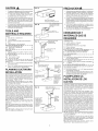 2
2
-
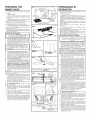 3
3
-
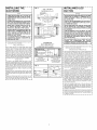 4
4
-
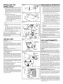 5
5
-
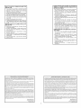 6
6
-
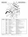 7
7
-
 8
8


Broan 462401 El manual del propietario
- Categoría
- Campanas de cocina
- Tipo
- El manual del propietario
en otros idiomas
- English: Broan 462401 Owner's manual
Artículos relacionados
-
Broan F402408 El manual del propietario
-
Broan-NuTone F403604 Manual de usuario
-
Broan-NuTone ACS30 Manual de usuario
-
NuTone F40000 SERIES Guía de instalación
-
Broan 463004 Manual de usuario
-
-
Broan-NuTone 462404 Manual de usuario
-
Broan 463608 Manual de usuario
-
Broan 433022 El manual del propietario