Improved CH COPY operation
8 RIVAGE PM series V3 Supplemental Manual
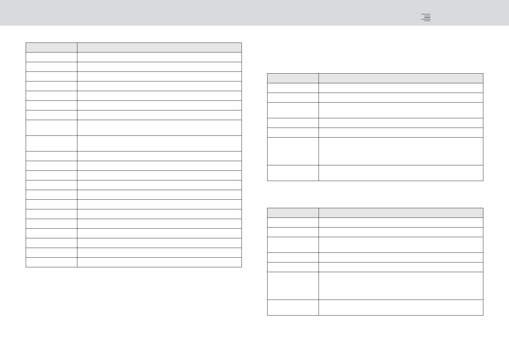
Parameters to copy
*1 Output channels only
If you turn on the WITH PLUGINS button to include the plug-ins in the copy source, and if the pair
setting of the copy-source channel(s) differs from that of the copy-destination channel(s), the
following operation will occur.
The copy source is a mono channel and the copy destination is also a mono channel:
*1 Excluding Dual type and Stereo type
The copy source is a stereo channel pair and the copy destination is also a stereo channel pair:
*1 The GEQ link settings on the copy destination will not be changed.
*2 Excluding Dual type and Stereo type
Parameter Description
NAME Channel name, color, icon
ANALOG GAIN Gain, phantom power on/off, GANG, gain compensation, M/S decode
SILK SILK settings
PHASE Ø
DIGITAL GAIN Gain, GANG
HPF/LPF On/off, cutoff frequency, type
EQ On/off, type, attenuator, band settings
DYNA 1
DYNA 2
On/off, type, type-specific parameters, key-in (filter, Q, cutoff frequency)
INSERT 1
INSERT 2
On/off, points
MIX SEND Level, PRE/POST, FOLLOW settings
MATRIX SEND Level, PRE/POST, FOLLOW settings
DIRECT OUT On/off, level, points, FOLLOW settings
DELAY On/off, delay time, points, GANG
FADER Level
CH ON On/off
MIX ON On/off
MATRIX ON On/off
SURR Surround settings (on/off, positioning, DIV, LFE)
TO STEREO TO STEREO settings (on/off, mode, points
*1
, PAN, BALANCE, CSR)
DCA ASSIGN DCA assign settings
MUTE ASSIGN Mute assign settings
Copy source Copy destination
31BandGEQ Copy the source and patch. (On, Band/Gain, Limit)
Flex15GEQ Copy the source and patch. (On, Band/Gain, Limit)
8BandPEQ Copy the source and patch. (On, Type, Band/Gain, Band/Q, Band/Bypass,
Band/Freq., Low Shel., High Shel.)
AutoMixer Assign an available channel. (Parameters will not be copied.)
OutBoard Select OutBoard as the copy destination. (No patching)
Effect Copy and patch (if the copy source is a Dual type) (including parameters
and bypass settings).
Copy and patch the L channel (if the copy source is a normal type
*1
)
(including parameters and bypass settings).
BLANK Clear the insert module patch on the copy destination channel. (The DSP
allocation used on the copy destination will be retained.)
Copy source Copy destination
31BandGEQ Copy the source and patch. (On, Band/Gain, Limit)
*1
Flex15GEQ Copy the source and patch. (On, Band/Gain, Limit)
*1
8BandPEQ Copy the source and patch. (On, Type, Band/Gain, Band/Q, Band/Bypass,
Band/Freq., Low Shel., High Shel.)
*1
AutoMixer Assign two available channels. (Parameters will not be copied.)
OutBoard Select OutBoard as the copy destination. (No patching)
Effect Copy and patch (if the copy source is a Stereo type) (including parameters
and bypass settings).
Copy and patch both L and R channels (if the copy source is a normal
type
*2
) (including parameters and bypass settings).
BLANK Clear the insert module patch on the copy destination channel. (The DSP
allocation used on the copy destination will be retained.)


