Yamaha PM10 Guía de instalación
- Categoría
- Ecualizadores de audio
- Tipo
- Guía de instalación

CONTROL SURFACE
CS-R10
CS-R10-S
System Setup Guide
EN

RIVAGE PM10 System Setup Guide
2
Explanation of Graphical Symbols
Explication des symboles
The lightning flash with arrowhead symbol within an equilateral triangle is intended to alert the user to the presence of uninsulated “danger-
ous voltage” within the product’s enclosure that may be of sufficient magnitude to constitute a risk of electric shock to persons.
L’éclair avec une flèche à l’intérieur d’un triangle équilatéral est destiné à attirer l’attention de l’utilisateur sur la présence d’une « tension
dangereuse » non isolée à l’intérieur de l’appareil, pouvant être suffisamment élevée pour constituer un risque d’électrocution.
The exclamation point within an equilateral triangle is intended to alert the user to the presence of important operating and maintenance (ser-
vicing) instructions in the literature accompanying the product.
Le point d’exclamation à l’intérieur d’un triangle équilatéral est destiné à attirer l’attention de l’utilisateur sur la présence d’instructions
importantes sur l’emploi ou la maintenance (réparation) de l’appareil dans la documentation fournie.
IMPORTANT SAFETY
INSTRUCTIONS
1 Read these instructions.
2 Keep these instructions.
3 Heed all warnings.
4 Follow all instructions.
5 Do not use this apparatus near water.
6 Clean only with dry cloth.
7 Do not block any ventilation openings. Install in accordance with the
manufacturer’s instructions.
8 Do not install near any heat sources such as radiators, heat registers,
stoves, or other apparatus (including amplifiers) that produce heat.
9 Do not defeat the safety purpose of the polarized or grounding-type
plug. A polarized plug has two blades with one wider than the other. A
grounding type plug has two blades and a third grounding prong. The
wide blade or the third prong are provided for your safety. If the pro-
vided plug does not fit into your outlet, consult an electrician for
replacement of the obsolete outlet.
10 Protect the power cord from being walked on or pinched particularly
at plugs, convenience receptacles, and the point where they exit from
the apparatus.
11 Only use attachments/accessories specified by the manufacturer.
12 Use only with the cart, stand, tripod, bracket, or
table specified by the manufacturer, or sold with
the apparatus. When a cart is used, use caution
when moving the cart/apparatus combination to
avoid injury from tip-over.
13 Unplug this apparatus during lightning storms
or when unused for long periods of time.
14 Refer all servicing to qualified service personnel. Servicing is
required when the apparatus has been damaged in any way, such as
power-supply cord or plug is damaged, liquid has been spilled or
objects have fallen into the apparatus, the apparatus has been
exposed to rain or moisture, does not operate normally, or has been
dropped.
(UL60065_03)
PRÉCAUTIONS CONCER-
NANT LA SÉCURITÉ
1 Lire ces instructions.
2 Conserver ces instructions.
3 Tenir compte de tous les avertissements.
4 Suivre toutes les instructions.
5 Ne pas utiliser ce produit à proximité d’eau.
6 Nettoyer uniquement avec un chiffon propre et sec.
7 Ne pas bloquer les orifices de ventilation. Installer l’appareil confor-
mément aux instructions du fabricant.
8 Ne pas installer l’appareil à proximité d’une source de chaleur comme
un radiateur, une bouche de chaleur, un poêle ou tout autre appareil
(y compris un amplificateur) produisant de la chaleur.
9 Ne pas modifier le système de sécurité de la fiche polarisée ou de la
fiche de terre. Une fiche polarisée dispose de deux broches dont une
est plus large que l’autre. Une fiche de terre dispose de deux broches
et d’une troisième pour le raccordement à la terre. Cette broche plus
large ou cette troisième broche est destinée à assurer la sécurité de
l’utilisateur. Si la fiche équipant l’appareil n’est pas compatible avec
les prises de courant disponibles, faire remplacer les prises par un
électricien.
10 Acheminer les cordons d’alimentation de sorte qu’ils ne soient pas
piétinés ni coincés, en faisant tout spécialement attention aux fiches,
prises de courant et au point de sortie de l’appareil.
11 Utiliser exclusivement les fixations et accessoires spécifiés par le
fabricant.
12 Utiliser exclusivement le chariot, le stand, le
trépied, le support ou la table recommandés par
le fabricant ou vendus avec cet appareil. Si
l’appareil est posé sur un chariot, déplacer le
chariot avec précaution pour éviter tout risque
de chute et de blessure.
13 Débrancher l’appareil en cas d’orage ou
lorsqu’il doit rester hors service pendant une période prolongée.
14 Confier toute réparation à un personnel qualifié. Faire réparer l’appa-
reil s’il a subi tout dommage, par exemple si la fiche ou le cordon
d’alimentation est endommagé, si du liquide a coulé ou des objets
sont tombés à l’intérieur de l’appareil, si l’appareil a été exposé à la
pluie ou à de l’humidité, si l’appareil ne fonctionne pas normalement
ou est tombé.
(UL60065_03)
CAUTION:
TO REDUCE THE RISK OF ELECTRIC SHOCK,
DO NOT REMOVE COVER (OR BACK).
NO USER-SERVICEABLE PARTS INSIDE.
REFER SERVICING TO QUALIFIED SERVICE PERSONNEL.
ATTENTION :
POUR RÉDUIRE LES RISQUES D'ÉLECTROCUTION, NE PAS RETIRER
LE CAPOT (OU LE DOS). NE CONTIENT PAS DE PIÈCES NÉCESSITANT
L'INTERVENTION DE L'UTILISATEUR. POUR TOUTE INTERVENTION,
FAIRE APPEL À DES PROFESSIONNELS QUALIFIÉS.
ATTENTION
RISQUE DE CHOC
ELECTRIQUE-NE PAS OUVRIR
The above warning is located on the rear of the unit. L’avertissement ci-dessus est situé sur l’arrière de l’unité.
WARNING
TO REDUCE THE RISK OF FIRE OR ELECTRIC SHOCK, DO NOT
EXPOSE THIS APPARATUS TO RAIN OR MOISTURE.
AVERTISSEMENT
POUR RÉDUIRE LES RISQUES D’INCENDIE OU DE DÉCHARGE
ÉLECTRIQUE, N’EXPOSEZ PAS CET APPAREIL À LA PLUIE OU À
L’HUMIDITÉ.

RIVAGE PM10 System Setup Guide
3
1. IMPORTANT NOTICE: DO NOT MODIFY THIS UNIT!
This product, when installed as indicated in the instructions con-
tained in this manual, meets FCC requirements. Modifications not
expressly approved by Yamaha may void your authority, granted by
the FCC, to use the product.
2. IMPORTANT: When connecting this product to accessories and/
or another product use only high quality shielded cables. Cable/s
supplied with this product MUST be used. Follow all installation
instructions. Failure to follow instructions could void your FCC
authorization to use this product in the USA.
3. NOTE: This product has been tested and found to comply with the
requirements listed in FCC Regulations, Part 15 for Class “B” digital
devices. Compliance with these requirements provides a reason-
able level of assurance that your use of this product in a residential
environment will not result in harmful interference with other elec-
tronic devices. This equipment generates/uses radio frequencies
and, if not installed and used according to the instructions found in
the users manual, may cause interference harmful to the operation
of other electronic devices. Compliance with FCC regulations does
(class B)
not guarantee that interference will not occur in all installations. If
this product is found to be the source of interference, which can be
determined by turning the unit “OFF” and “ON”, please try to elimi-
nate the problem by using one of the following measures:
Relocate either this product or the device that is being affected by
the interference.
Utilize power outlets that are on different branch (circuit breaker or
fuse) circuits or install AC line filter/s.
In the case of radio or TV interference, relocate/reorient the
antenna. If the antenna lead-in is 300 ohm ribbon lead, change the
lead-in to co-axial type cable.
If these corrective measures do not produce satisfactory results,
please contact the local retailer authorized to distribute this type of
product. If you can not locate the appropriate retailer, please con-
tact Yamaha Corporation of America, Electronic Service Division,
6600 Orangethorpe Ave, Buena Park, CA90620
The above statements apply ONLY to those products distributed by
Yamaha Corporation of America or its subsidiaries.
FCC INFORMATION (U.S.A.)
COMPLIANCE INFORMATION STATEMENT
(DECLARATION OF CONFORMITY PROCEDURE)
Responsible Party : Yamaha Corporation of America
Address : 6600 Orangethorpe Ave., Buena Park, Calif.
90620
Telephone : 714-522-9011
Type of Equipment : Control Surface
Model Name : CS-R10, CS-R10-S
This device complies with Part 15 of the FCC Rules.
Operation is subject to the following two conditions:
1) this device may not cause harmful interference, and
2) this device must accept any interference received including interfer-
ence that may cause undesired operation.
See user manual instructions if interference to radio reception is sus-
pected.
(FCC DoC)
ADVARSEL!
Lithiumbatteri—Eksplosionsfare ved fejlagtig håndtering. Udskiftning
må kun ske med batteri af samme fabrikat og type. Levér det brugte
batteri tilbage til leverandoren.
VARNING
Explosionsfara vid felaktigt batteribyte. Använd samma batterityp eller
en ekvivalent typ som rekommenderas av apparattillverkaren.
Kassera använt batteri enligt fabrikantens instruktion.
VAROITUS
Paristo voi räjähtää, jos se on virheellisesti asennettu. Vaihda paristo
ainoastaan laitevalmistajan suosittelemaan tyyppiin. Hävitä käytetty
paristo valmistajan ohjeiden mukaisesti.
(lithium caution)
NEDERLAND / THE NETHERLANDS
• Dit apparaat bevat een lithium batterij voor geheugen back-up.
• This apparatus contains a lithium battery for memory back-up.
• Raadpleeg uw leverancier over de verwijdering van de batterij op het
moment dat u het apparaat ann het einde van de levensduur of gelieve
dan contact op te nemen met de vertegenwoordiging van Yamaha in
uw land.
• For the removal of the battery at the moment of the disposal at the end
of life please consult your retailer or Yamaha representative office in
your country.
• Gooi de batterij niet weg, maar lever hem in als KCA.
• Do not throw away the battery. Instead, hand it in as small chemical
waste.
(lithium disposal)
This product contains a battery that contains perchlorate material.
Perchlorate Material—special handling may apply,
See www.dtsc.ca.gov/hazardouswaste/perchlorate.
* This applies only to products distributed by
YAMAHA CORPORATION OF AMERICA.
(Perchlorate)
이 기기는 가정용(B급) 전자파적합기기로서 주로
가정에서 사용하는 것을 목적으로 하며, 모든
지역에서 사용할 수 있습니다.
(class b korea)

RIVAGE PM10 System Setup Guide
4
PRECAUTIONS
PLEASE READ CAREFULLY
BEFORE PROCEEDING
Please keep this manual in a safe place for
future reference.
WARNING
Always follow the basic precautions listed below to avoid
the possibility of serious injury or even death from
electrical shock, short-circuiting, damages, fire or other
hazards. These precautions include, but are not limited
to, the following:
Power supply/power cord
• Do not place the power cord near heat sources such as
heaters or radiators, and do not excessively bend or otherwise
damage the cord, place heavy objects on it, or place it in a
position where anyone could walk on, trip over, or roll anything
over it.
• Only use the voltage specified as correct for the device. The
required voltage is printed on the name plate of the device.
• Use only the supplied power cord/plug.
If you intend to use the device in an area other than in the one
you purchased, the included power cord may not be
compatible. Please check with your Yamaha dealer.
• Check the electric plug periodically and remove any dirt or
dust which may have accumulated on it.
• This product receives power from multi sources. When setting
up the product, make sure that the AC outlet you
are using is easily accessible. If some trouble or
malfunction occurs, immediately turn off the power
switch and disconnect all plugs from the outlet.
Even when the power switch is turned off, as long
as the power cord is not unplugged from the wall
AC outlet, the product will not be disconnected
from the power source.
• Remove the electric plug from the outlet when the device is
not to be used for extended periods of time, or during
electrical storms.
• Be sure to connect to an appropriate outlet with a protective
grounding connection.
Do not open
• This device contains no user-serviceable parts. Do not open
the device or attempt to disassemble the internal parts or
modify them in any way. If it should appear to be
malfunctioning, discontinue use immediately and have it
inspected by qualified Yamaha service personnel.
Water warning
• Do not expose the device to rain, use it near water or in damp
or wet conditions, or place on it any containers (such as
vases, bottles or glasses) containing liquids which might spill
into any openings. If any liquid such as water seeps into the
device, turn off the power immediately and unplug the power
cord from the AC outlet. Then have the device inspected by
qualified Yamaha service personnel.
• Never insert or remove an electric plug with wet hands.
Hearing loss
• Avoid setting all equalizer controls and faders to their
maximum. Depending on the condition of the connected
devices, doing so may result in feedback that can cause
hearing loss and damage the speakers.
• Do not use the headphones for a long period of time at a high
or uncomfortable volume level, since this can cause
permanent hearing loss. If you experience any hearing loss or
ringing in the ears, consult a physician.
• When turning on the AC power in your audio system, always
turn on the power amplifier LAST, to avoid hearing loss and
speaker damage. When turning the power off, the power
amplifier should be turned off FIRST for the same reason.
Fire warning
• Do not place any burning items or open flames near the
device, since they may cause a fire.
If you notice any abnormality
• If any of the following problems occur, immediately turn off the
power switch and disconnect the electric plug from the outlet.
- The power cord or plug becomes frayed or damaged.
- Unusual smells or smoke are emitted.
- Some object has been dropped into the device.
- There is a sudden loss of sound during use of the device.
- Cracks or other visible damage appear on the device.
Then have the device inspected or repaired by qualified
Yamaha service personnel.
• If this device should be dropped or damaged, immediately
turn off the power switch, disconnect the electric plug from the
outlet, and have the device inspected by qualified Yamaha
service personnel.
CAUTION
Always follow the basic precautions listed below to avoid
the possibility of physical injury to you or others, or
damage to the device or other property. These
precautions include, but are not limited to, the following:
Power supply/power cord
• When removing the electric plug from the device or an outlet,
always hold the plug itself and not the cord. Pulling by the
cord can damage it.
• To disconnect the device from the mains, unplug both power
cords.
Location
• Do not place the device in an unstable position where it might
accidentally fall over and cause injuries.
• Do not block the vents. This device has ventilation holes at the
rear/under the front to prevent the internal temperature from
becoming too high. In particular, do not place the device on
its side or upside down. Inadequate ventilation can result in
overheating, possibly causing damage to the device(s), or
even fire.
• Do not place the device in a location where it may come into
contact with corrosive gases or salt air. Doing so may result in
malfunction.
PA_en_4 1/3
(multi power
source model)

RIVAGE PM10 System Setup Guide
5
• Avoid being near the device during a disaster, such as an
earthquake. Since the device may turn over or fall and cause
injury, stay away from the device quickly and move to a safe
place.
• Before moving the device, remove all connected cables.
• When transporting or moving the device, always use four or
more people. Attempting to lift the device by yourself may
damage your back, result in other injury, or cause damage to
the device itself.
• Keep device away from the reach of children.
Connections
• Before connecting the device to other devices, turn off the
power for all devices. Also, before turning the power of all
devices on or off, make sure that all volume levels are set to
the minimum. Failing to do so may result in electric shock, or
equipment damage.
Maintenance
• Remove the power plug from the AC outlet when cleaning the
device.
Handling caution
• Do not insert your fingers or hands in any gaps or openings on
the device (vents, etc.).
• Avoid inserting or dropping foreign objects (paper, plastic,
metal, etc.) into any gaps or openings on the device (vents,
panel, etc.) If this happens, turn off the power immediately
and unplug the power cord from the AC outlet. Then have the
device inspected by qualified Yamaha service personnel.
• Do not rest your weight on the device or place heavy objects
on it. Avoid applying excessive force to the buttons, switches,
or connectors.
Backup battery
• Do not replace the backup battery by yourself. Doing so may
cause an explosion and/or damage to the device(s). If the
backup battery power is fully depleted, have qualified Yamaha
service personnel replace the battery.
NOTICE
To avoid the possibility of malfunction/damage to the
product, damage to data, or damage to other property,
follow the notices below.
Handling and maintenance
• Do not use the device in the vicinity of a TV, radio, AV
equipment, mobile phone, or other electric devices.
Otherwise, the device, TV, or radio may generate noise.
• Do not expose the device to excessive dust or vibration, or
extreme cold or heat (such as in direct sunlight, near a heater,
or in a car during the day), in order to prevent the possibility of
panel disfiguration, unstable operation, or damage to the
internal components.
• Do not place vinyl, plastic or rubber objects on the device,
since this might discolor the panel.
• When cleaning the device, use a dry and soft cloth. Do not
use paint thinners, solvents, cleaning fluids, or chemical-
impregnated wiping cloths.
• Condensation can occur in the device due to rapid, drastic
changes in ambient temperature—when the device is moved
from one location to another, or air conditioning is turned on or
off, for example. Using the device while condensation is
present can cause damage. If there is reason to believe that
condensation might have occurred, leave the device for
several hours without turning on the power until the
condensation has completely dried out.
• During extreme changes in temperature or humidity,
condensation may occur and water may collect on the surface
of the device. If water is left, the wooden parts may absorb the
water and be damaged. Make sure to wipe any water off
immediately with a soft cloth.
• Avoid setting all equalizer controls and faders to their
maximum. Depending on the condition of the connected
devices, doing so may cause feedback and may damage the
speakers.
• Do not apply oil, grease, or contact cleaner to the faders.
Doing so may cause problems with electrical contact or fader
motion.
• When turning on the AC power in your audio system, always
turn on the power amplifier LAST, to avoid speaker damage.
When turning the power off, the power amplifier should be
turned off FIRST for the same reason.
• Always turn the power off when the device is not in use.
Saving data
• This device has a built-in backup battery that maintains clock
data even when the device’s power is switched off. The
backup battery will eventually become depleted, however,
and when that happens the clock data will be lost. To prevent
loss of data be sure to replace the backup battery before it
becomes fully depleted. If you need to replace the backup
battery, then have qualified Yamaha service personnel replace
the backup battery. The average life of the internal backup
battery is approximately 5 years, depending on operating
conditions.
Connectors
• XLR-type connectors are wired as follows (IEC60268
standard): pin 1: ground, pin 2: hot (+), and pin 3: cold (–).
Yamaha cannot be held responsible for damage caused by
improper use or modifications to the device, or data that is
lost or destroyed.
Make sure that the front end
of the table will remain under
the front stabilizer legs.
PA_en_4 2/3

RIVAGE PM10 System Setup Guide
6
Information
About copyrights
Copying of the commercially available musical data including
but not limited to MIDI data and/or audio data is strictly
prohibited except for your personal use.
About functions/data bundled with the product
• Supply of this product does not convey a license nor imply
any right to distribute content created with this product in
revenue-generating broadcast systems (terrestrial, satellite,
cable and/or other distribution channels), streaming
applications (via Internet, intranets and/or other networks),
other content distribution systems (pay-audio or
audioondemand applications and the like) or on physical
media (compact discs, digital versatile discs, semiconductor
chips, hard drives, memory cards and the like). An
independent license for such use is required. For details,
please visit http://mp3licensing.com.
About this manual
• The illustrations and LCD screens as shown in this manual are
for instructional purposes only.
• Windows is a registered trademark of Microsoft(R)
Corporation in the United States and other countries.
• Apple, Mac, Macintosh, and iPad are trademarks of Apple
Inc., registered in the U.S. and other countries.
• The company names and product names in this manual are
the trademarks or registered trademarks of their respective
companies.
(rear_en_01)
(weee_eu_en_02)
European Models
Purchaser/User Information specified in EN55103-2:2009.
Conforms to Environments: E1, E2, E3 and E4
The model number, serial number, power requirements, etc., may
be found on or near the name plate, which is at the rear of the
unit. You should note this serial number in the space provided
below and retain this manual as a permanent record of your pur-
chase to aid identification in the event of theft.
Model No.
Serial No.
Information for users on collection and disposal of old
equipment:
This symbol on the products, packaging, and/or
accompanying documents means that used elec-
trical and electronic products should not be
mixed with general household waste. For proper
treatment, recovery and recycling of old prod-
ucts, please take them to applicable collection
points, in accordance with your national legisla-
tion.
By disposing of these products correctly, you will help to save
valuable resources and prevent any potential negative effects on
human health and the environment which could otherwise arise
from inappropriate waste handling.
For more information about collection and recycling of old prod-
ucts, please contact your local municipality, your waste disposal
service or the point of sale where you purchased the items.
For business users in the European Union:
If you wish to discard electrical and electronic equipment, please
contact your dealer or supplier for further information.
Information on Disposal in other Countries outside the European
Union:
This symbol is only valid in the European Union. If you wish to dis-
card these items, please contact your local authorities or dealer
and ask for the correct method of disposal.
PA_en_4 3/3

RIVAGE PM10 System Setup Guide
7
Introduction ............................8
Main Features ................................... 8
About manuals.................................. 8
About utility software........................ 9
Firmware updates ............................. 9
Conventions in this manual............... 9
Accessories (CS-R10, CS-R10-S)......... 9
System Overview....................10
Introducing the devices................... 10
About network card ........................ 13
About Dante ..........................14
Caution when using a
network switch................................ 14
About Connections ................14
Daisy Chain Network ...................... 14
Star Network................................... 15
Part Names & Functions ........16
Top panel ....................................... 16
Front panel ..................................... 28
Rear panel....................................... 29
Power Supply .........................32
Connecting to power sources.......... 32
Installing and Removing
Optional Cards .....................32
Installing a Mini-YGDAI card ........... 32
Removing the Mini-YGDAI card....... 33
Touch Screen .........................33
Basic touch screen operations ......... 33
On-screen user interface.................. 33
Viewing a touch screen ................... 35
Quick Guide ...........................35
Basic system configuration .............. 35
Installing an optional card ............... 36
Setting the Unit ID .......................... 38
Connecting the devices................... 38
Turning on the power to the
RIVAGE PM10 system ...................... 39
Setting the word clock .................... 39
Assigning channels to the
TWINLANe network ........................ 40
Patching the input ports.................. 41
Patching the output ports ............... 42
Setting the analog gain for HA
(Head Amp) .................................... 43
Sending an input channel signal to
the STEREO bus............................... 44
Check list ........................................ 45
Other Operations...................46
Initializing the unit to factory default
settings ........................................... 46
Adjusting the faders (Calibration
function) ......................................... 46
Troubleshooting ....................48
Specifications
(CS-R10, CS-R10-S)................49
General Specifications ..................... 49
Pin Assignment Table ...................... 53
Dimensional Diagrams .................... 54
Index......................................56
Contents

RIVAGE PM10 System Setup Guide
8
Thank you for purchasing the Yamaha RIVAGE PM10
digital mixing system. This product is suitable for the use
in a large-scale hall or event. This manual provides the
information and procedures required for audio
installation companies to plan and set up the audio
system. It also describes the set-up procedure and basic
operation for mixing engineers. In order to take full
advantage of this system’s superior functionality and enjoy
years of trouble-free use, please read this manual before
you use the product. After you have read the manual, keep
it in a safe place for future reference.
Main Features
The RIVAGE PM10 system features superb sound quality,
intuitive controls, and innovative functionality. It is a
state-of-the-art mixing system that supports a variety of
applications.
Superb sound quality
The design of the RIVAGE PM10 digital mixing system is
an uncomprised expression of Yamaha’s philosophy of Pro
Audio device design. This philosophy is called “white
canvas,” and suggests that the ideal starting point for sonic
creativity is pure, natural reproduction achieved through
the use of high quality analog circuits. Only then can
sound be colored effectively by a variety of aural paints for
the desired creative impact. Numerous processing options
(such as plug-ins, SILK, etc.) enable powerful sound
production capabilities in the digital domain. Through a
fusion of analog and digital technologies, the RIVAGE
PM10 has achieved both the creation of a pure,
transparent sound, and fluid capabilities for coloring that
sound.
Intuitive controls
The RIVAGE PM10 features a farther advanced top panel
controls, including large touch panel screens, a full
implementation of Yamaha’s acclaimed Selected Channel
interface, and highly user-friendly USER DEFINED
KEYS/KNOBS section and TOUCH AND TURN knobs.
This feature provides the system’s extraordinary
operability.
Innovative functionality
The RIVAGE PM10 also features abundant inputs and
outputs; flexible signal routing; powerful DSP engine
processing with two insert points; and scene memory and
library management that supports an enormous amount
of sophisticated requirements. The system also provides
numerous benefits for users by maintaining reliability
through power and network redundancy.
These core features are supported by state-of-the-art
technologies and an advanced level of product reliability
that have been cultivated through years of experience in
developing digital mixing consoles, such as the PM1D and
PM5D. The deep passion of Yamaha’s engineering team
has been infused into the RIVAGE PM10.
About manuals
• RIVAGE PM10 System Setup Guide (this book)
This guide describes an overview of the RIVAGE
PM10 system, and explains step by step how to set up
the system from connecting devices to producing
sound.
This guide also serves as a user guide for the CS-R10
and CS-R10-S. It explains part names and panel
functions.
• Manuals for other devices
The manuals for other devices describe part names and
functions of the corresponding devices.
These manuals are supplied with the corresponding
device packages.
•RIVAGE PM series Operation Manual
The Operation Manual provides detailed explanations
of all screens and functions, and includes step-by-step
procedures to help you operate the RIVAGE PM series.
• RIVAGE PM Editor Installation Guide
This guide describes how to install the RIVAGE PM
Editor.
•RIVAGE PM StageMix User Guide
This guide describes an iPad application that enables
you to control the RIVAGE PM series system
wirelessly.
Using the PDF manual
The Operation Manual and the Editor Installation
Guide are electronic files in PDF format. You can read
this book on a computer. Use Acrobat Reader to read
this book on screen, search for words very quickly,
print specific pages, or click links to display sections of
special interest. The ability to search for words, or to
follow links directly to relevant sections in the
document, are helpful attributes of this electronic file
format. We encourage you to take advantage of these
benefits.
You can download the latest Acrobat Reader
application from the website listed below.
http://www.adobe.com/
All manuals can be downloaded from the Yamaha website.
If necessary, you can review updated manual information,
which is always posted in the Yamaha website.
https://download.yamaha.com/
Introduction

RIVAGE PM10 System Setup Guide
9
About utility software
The RIVAGE PM10 system can be used with a variety of
utility software.
•RIVAGE PM Editor
This Windows application software enables you to
access the same functions that are available on the
control surface. You can use your computer to perform
off-line editing by preparing the RIVAGE PM10
system settings in advance, and to monitor and adjust
those settings (on-line monitoring/operation).
•RIVAGE PM StageMix
StageMix enables you to use your iPad to wirelessly
control the parameters of your Yamaha RIVAGE PM
series digital mixing console. StageMix offers the
sound engineer (who is away from the system) the
freedom to control parameters remotely, while
listening to the results from the vantage point of the
performers.
Information on this software application is available on
the Yamaha Pro Audio website:
https://www.yamaha.com/proaudio/
For information regarding how to download or install
Editor or StageMix, as w
ell as their various setting
details, please refer to the website listed above or to the
Installation Guide attached to the downloaded
software program.
Firmware updates
You can update the unit firmware to improve operations,
add func
tions, and correct possible malfunctions.
Details on updating the firmware are available on the
following Yamaha Pro Audio website:
https://www.yamaha.com/proaudio/
For information on updating and setting up the unit,
please refer to the firmware update guide available on the
website.
Conventions in this manual
In this manual, switch-type controllers on the panel are
called “keys.” Control knobs on the panel are called
“knobs.” Some knobs rotate from a minimum value to a
maximum value, while others rotate endlessly.
Virtual buttons displayed on the screen are called
“buttons,” and virtual knobs are called “knobs.”
Controls located on the panel are enclosed in square
brackets [ ] (e.g., [CUE] key) to distinguish them from
virtual buttons and knobs displayed on screen. For certain
controls, the name of the section appears before the
brackets (e.g., Selected Channel [ISOLATE] key).
Accessories
(CS-R10, CS-R10-S)
•AC Power Cords (×2)
(The connector shape may vary depending on the sales
area.)
•Dust cover
• Gooseneck Lamps LA1L
(×4 for CS-R10 , ×3 for CS-R10-S)
•System Setup Guide (this book)

RIVAGE PM10 System Setup Guide
10
Introducing the devices
The RIVAGE PM10 system consists of the following components:
System Overview
Control surfaces DSP engine I/O racks
CS-R10
CS-R10-S
DSP-R10 RPio622
RPio222
The control surfaces enable you to perform general
operations on the RIVAGE PM10 system.
The DSP engine handles mixing and plug-
in processing, and all other audio
processing for the RIVAGE PM10 system.
The I/O racks transfer analog and
digital audio signals to and from the
DSP engine.

RIVAGE PM10 System Setup Guide
11
NOTE
• Pleas
e refer to the owner’s manual supplied with the host device for information on installing the I/O cards.
• For detailed information on
I/O card settings, refer to the owner’s manual f
or the I/O card.
For the latest information on which I/O cards can be used with the system, visit the Yamaha Pro Audio website at:
https://www.yamaha.com/proaudio/
RY cards HY cards
RY16-ML-SILK
This is a 16-channel mic/line input card.
It features SILK digital processing technology that has been co-developed by
Rupert Neve Designs and Yamaha.
RY16-DA
This card features 16-channel analog outputs.
RY16-AE
This card features 16-channel digital I/Os that support the AES/EBU format.
A sampling rate converter is built in for both inputs and outputs.
HY256-TL
HY256-TL-SMF
This digital I/O card supports TWINLANe (Yamaha’s
proprietary audio transfer network protocol). It can
handle 256 channels and be installed in the HY card
slot. HY256-TL uses multimode fiber optic cables.
HY256-TL-SMF uses singlemode fiber optic cables.
HY144-D
This digital I/O card supports the Dante digital audio
network. It can handle 144 channels and be installed
in the HY card slot.

RIVAGE PM10 System Setup Guide
12
About Console Network and I/O Network
• Console Network
A DSP engine is equipped with a special control
surface terminal. You can connect a control surface to
a DSP engine. A network created by the control surface
and a DSP engine is called a “Console Network.”
•I/O Network
A DSP engine and I/O racks are connected via a
TWINLANe network, using an HY card slot. A
network created by a DSP engine and I/O racks is
called an “I/O Network.”
TWINLANe network
TWINLANe is Yamaha’s proprietary audio transfer
network protocol. With this protocol, 400-channel digital
audio and control signals can be transfered via a single
cable simultaneously.
To connect devices, first install a TWINLANe network
card in an HY card slot of each device, then use fiber optic
cables to connect the TWINLANe network cards in a ring
network topology.
* If the number of connected devices is much larger, or if the
total length of all cables is too long, the listed value may not
apply.
NOTE
Yamaha recommends that you use opticalCON DUO fiber cable
made by Neutrik. In general, fiber optic cables are susceptible to
bending or pulling. Use a fiber optic cable that features a strong
plastic jacket and lock mechanism to avoid cable-related
problems.
About cleaning
If dirt or dust attached to the contact surface of jacks on
the fiber optic cables or connectors on the device, data
may not be transferred properly. Clean the contact surface
of jacks and connectors regularly using a commercially-
available fiber optic cleaning tool.
Console Network
I/O Network
(TWINLANe)
DSP Engine
Control Surface
I/O Rack I/O Rack
Transferred data 400-channel audio signal and control
signal
Sampling frequency 44.1 kHz, 48 kHz, 88.2 kHz, 96 kHz
Network latency* 11 sample@Fs= 44.1 kHz (0.25 msec)
11 sample@Fs= 48 kHz (0.23 msec)
12 sample@Fs= 88.2 kHz (0.14 msec)
12 sample@Fs= 96 kHz (0.13 msec)
Bit-length 32-bit
Topology Ring

RIVAGE PM10 System Setup Guide
13
Ring connection
A TWINLANe network uses a ring topology, which
provides redundancy in case of broken cables. If a cable in
the network breaks down for some reason, the signal will
be automatically re-routed and audio will flow without
interruption. Even if a device in the network malfunctions,
other working devices will be able to continue
communicating.
■ Normal situation
■ When a cable is broken
About network card
The RIVAGE PM10 system uses a TWINLANe network
card to configure the I/O network.
* Total cable length for the ring connection using TWINLANe
cards can span up to 6 kilometers.
.....
INOUT NINIOUT OUT
Device
TWINLANe
Network Card
Device
TWINLANe
Network Card
Device
TWINLANe
Network Card
INOUT INOUT INOUT
INOUT INOUT INOUT
Even if a cable is severed at one point, the
signal will be re-routed automatically and
communication will continue without
interruption.
TWINLANe network
card
HY256-TL HY256-TL-SMF
Connection cable Multimode fiber
optic cable
Singlemode fiber
optic cable
Maximum cable length
between devices
Max. 300m Max. 2km*
Maximum number of
channels
256-in/256-out

RIVAGE PM10 System Setup Guide
14
Dante is a network audio protocol developed by the
Audinate. Within a Giga-bit Ethernet (GbE), Dante
delivers multi-channel audio signals at various sampling
frequencies and bit rates, as well as device control signals.
Visit the Audinate website for more details on
Dante.
http://www.audinate.com/
More information on Dante is also posted on the Yamaha
Pro Audio website:
https://www.yamaha.com/proaudio/
Caution when using a
network switch
Please do not use the EEE function (*) of network switches
in a Dante network.
Although power management should be negotiated
automatically in switches that support EEE, some switches
do not perform the negotiation properly.
This may cause EEE to be enabled in Dante networks
when it is not appropriate, resulting in poor
synchronization performance and occasional dropouts.
Therefore we strongly recommend the following:
• When using a managed switch, turn off the EEE
function of all ports used by Dante. Do not use a
switch that is unable to turn off the EEE function.
• If using an unmanaged switch, do not use a switch that
supports the EEE function. Such switches are unable to
turn off the EEE function.
* EEE (Energy Efficient Ethernet) is a technology that reduces switch
power consumption during periods of low network traffic. It is also
known as Green Ethernet or IEEE802.3az.
There are two ways to connect the I/O rack (R series) to a
Dante network. Please refer to the Operation Manual and
other related documents for more information on how to
set up and and connect your Dante-enabled devices.
NOTE
A daisy chain connection is suitable for a simple system with a
small number of devices.
Use a star network if a large number of devices are connected.
Daisy Chain Network
A daisy chain is a wiring scheme in which multiple devices
are connected together in sequence. In this way,
networking is simple and requires no network switches.
If you connect a large number of devices, you must set a
higher latency value to avoid skipping audio that could be
caused by an increased delay in signal transfer among the
devices. Also, if a connection is broken in a daisy chain
network, the signal flow is interrupted at that point and no
signal will be transferred beyond that point.
About Dante About Connections
Rio3224-D2 (UNIT ID: Y001)
Rio3224-D2 (UNIT ID: Y002)
SECONDARY
PRIMARY
PRIMARY
HY144-D
DSP-R10
CS-R10

RIVAGE PM10 System Setup Guide
15
Star Network
In a star network, each device is connected to a central
network switch. Using a GbE-compatible network switch
enables you to configure a wide-band, large-scale network.
We recommend a network switch that features various
functions to control and monitor the network (such as
Qos, the ability to assign priority to data flows - e.g., clock
synchronization or audio transmission on certain data
circuits.)
With this topology, it is common to configure a redundant
network so that an unexpected network problem will not
affect any audio or otherwise stable communications.
About Redundant Networks
A redundant network consists of two circuits, a primary
circuit and a secondary circuit. Normally, the network
operates on the primary circuit. However, if the primary
connection is broken, the secondary circuit will
automatically take over communications. Therefore, using
a redundant network with a star topology would increase
communication stability relative to a daisy chain network.
NOTE
If you have been using an HY144-D card on RIVAGE PM10
V1
.51 or earlier, you must update the firmware for the HY144-D.
Details on updating the firmware are available on the following
Yamaha Pro Audio website:
https://www.yamaha.com/proaudio/
HY144-D
SECONDARY
SECONDARY
SECONDARYPRIMARY
PRIMARY
PRIMARY
Rio3224-D2 (UNIT ID: Y001)
Rio3224-D2 (UNIT ID: Y002)
Network switch A
Network switch B
Primary Dante
Secondary Dante
DSP-R10
CS-R10

RIVAGE PM10 System Setup Guide
16
Top panel
A Touch Screen section ➔ page 24
B Channel Strip section ➔ page 25
C Selected Channel section ➔ page 17
D UTILITY section ➔ page 21
E SCENE MEMORY section ➔ page 22
F USER DEFINED KEYS/KNOBS section ➔ page 23
Part Names & Functions
A
B
CD
FB
E
CS-R10-S
A
B
CD
FB
E
CS-R10

RIVAGE PM10 System Setup Guide
17
Selected Channel section
This section enables you to adjust parameters for the selected channel.
[ISOLATE] key
Switches Isolate on or off. The Isolate function
enables you to protect the channel from any recall
operations for scenes or libraries. Also, if
the“isolated” channel belongs to any DCA, Mute
group, or other category, the channel will be
unaffected by the controls of that group.
[RCL SAFE] key
Switches Recall Safe on or off.
The Recall Safe function protects certain parameters
of a channel from scene recall operations.
[MUTE SAFE] key
Switches Mute Safe on or off.
The Mute Safe function protects a channel from mute
operations.
TO ST [A]/[B] keys
Switch on or off the signal sent from the input
channel to stereo bus A or B.
Meter LEDs
Displays the channel signal level.
[CUE] key
Switches channel cue send on or off.

RIVAGE PM10 System Setup Guide
18
[PAN/BAL] knob
Sets the panning/balance of the signal sent to the
stereo buses.
[Fn] (Function) key
Executes the pre-assigned function.
[ON] key
Switches the channel on or off.
[FADER] knob
Adjusts the channel fader level.
[COPY] key
Copies a channel parameter.
[PASTE] key
Pastes the copied channel parameter.
Channel name display
Indicates the channel number and name, fader value,
etc.
Channel color indicator
Indicates the channel color.
[INC]/[DEC] keys
Switch channels to edit parameters.
INPUT/A.GAIN/SILK/D.GAIN/DELAY
INPUT [A]/[B] keys
Switch the input source for the selected input
channel.
[ANALOG GAIN] knob
Sets the analog gain for the head amp.
[+48V] key
Switches phantom power (+48V) on or off.
SILK [TEXTURE] knob
Adjusts the intensity of SILK processing.
SILK [ON] key
Switches SILK on or off.
SILK processing can be applied only to specific
channels to bring the corresponding parts to life
within the mix, or to all channels to add depth and
perspective to the mix overall.
SILK [BLUE/RED] key
Toggles between BLUE and RED: “BLUE” for solidity
and power, and “RED” for sparkling energy.
[DIGITAL GAIN] knob
Sets the digital gain of the channel.
GC indicator
Lights up when GC (GAIN COMPENSATION) is
enabled.
[ ] (Phase) key
Reverses the phase of the input signal.
DELAY [ON] key
Switches Delay on or off.
DELAY display
Indicates the delay value.
[DELAY] knob
Sets the delay value.

RIVAGE PM10 System Setup Guide
19
EQUALIZER
EQUALIZER [1-4]/[(5-8)] keys
Switch the EQ bands for which you want to make
settings.
Pressing both [1-4] and [5-8] keys simultaneously
will set the gain for all bands to 0 (FLAT).
EQUALIZER [ON] key
Switches EQ on or off.
EQUALIZER [SHELF] key
Switches peaking filter to shelving filter.
EQUALIZER display
Indicates parameters for each EQ band.
EQUALIZER [Q] knob
Specifies the Q value.
EQUALIZER [FREQUENCY] knob
Sets the frequency.
EQUALIZER [GAIN] knob
Sets the gain.
LPF/HPF
LPF/HPF [FREQUENCY] knobs
Specify the cutoff frequency of LPF and HPF
respectively.
LPF/HPF display
Indicates the LPF and HPF settings.
LPF/HPF [ON] keys
Switch the LPF and HPF on or off respectively.
LPF/HPF [SLOPE] keys
Switch the LPF and HPF slope settings respectively.
DCA/MUTE/INSERT
DCA ASSIGN LEDs
Indicate the assigned DCAs.
MUTE GROUP ASSIGN LEDs
Indicate the assigned Mute Groups.
INSERT [PLUG-INS] key
Enables you to recall a parameter setting screen for
the inserted plug-ins.
INSERT 1/2 [ON] keys
Switch the INSERT1 and INSERT2 on or off
respectively.

RIVAGE PM10 System Setup Guide
20
DYNAMICS
DYNAMICS 1/2 IN LEDs
Indicates the Dynamics input level.
DYNAMICS 1/2 GR LEDs
Indicates the amount of Dynamics gain reduction.
DYNAMICS 1/2 [<]/[>] keys
Switch parameters that are indicated on the
DYNAMICS display.
DYNAMICS 1/2 setting knobs
Set parameters that are indicated on the DYNAMICS
display.
DYNAMICS 1/2 display
Indicates the Dynamics parameters.
DYNAMICS 1/2 [ON] key
Switches Dynamics on or off.
MIX/MATRIX SENDS
MIX/MATRIX knobs
Adjust the send levels for the corresponding buses.
MIX/MATRIX SENDS [PRE] keys
Toggle the send point between PRE and POST. If a
key lights up, the send point is set to PRE.
MIX/MATRIX SENDS [ON] keys
Switch the send signal to the corresponding bus on or
off.
MIX/MATRIX SENDS display
Indicates the corresponding bus.
MIX/MATRIX SENDS [MIX]/[MATRIX] keys
Switch the type of the send destination bus.
MIX/MATRIX SENDS [1-12]/[13-24]/[25-36]/
[37-48]/[49-60]/[61-72] keys
Selects a bank for the send destination bus.

RIVAGE PM10 System Setup Guide
21
UTILITY section
POWER Indicator
Lights when AC power to the unit is ON. If both
power switches A and B are turned on, this indicator
will light green. If either power switch A or B is
turned on, it will light red. If the RIVAGE PM 10
system is not started, it will light orange.
USB port
Enables you to connect a USB device (such as a
mouse, keyboard, or USB flash drive). Use a USB
flash drive to store the system’s internal data and to
load the stored data into the system.
■ Supported USB flash drive format
The FAT16 and FAT32 formats are supported.
■ Write Protection
Some USB flash drives feature write protection that
prevents data from being erased inadvertently.
If your USB flash drive contains important data, we
suggest that you use write protection to prevent
accidental erasure.
On the other hand, you will need to make sure that
your USB flash drive’s write-protect setting is turned
off before you save data onto the USB flash drive.
For the latest information on which USB flash drives
ca
n be used with the system, visit the Yamaha Pro
Audio website at:
https://www.yamaha.com/proaudio/
NOTICE
Do not remove the USB flash drive from the USB
connector or turn off the power to the unit while the unit is
accessing data, e.g., saving, loading or deleting data.
Doing so may damage your flash drive, or may damage the
data in the unit or on your media device.
RECORDING port
Enables you to connect a USB flash drive to record
and play back audio files. Supported file formats
include WAV and MP3.
For the latest information on what USB flash drives
can be used with the system, visit the Yamaha Pro
Audio website at:
https://www.yamaha.com/proaudio/
[SYSTEM] key
Press this key to display information about the
RIVAGE PM10 system on the touch screens.
Press and hold down the key for two seconds or
longer to shut down the control section of the console
(➔ page 31). Be sure to shut down before turning off
the power to the unit.
TALKBACK jack
This is a balanced XLR-3-31 jack to which a talkback
mic can be connected.
+48V indicator
Lights up when +48V phantom power is supplied to
the TALKBACK jack.
TALKBACK [LEVEL] knob
Adjusts the input level of the mic connected to the
TALKBACK jack.
TALKBACK [ON] key
Switches the Talkback function on or off.
MONITOR A/B [LEVEL] knobs
Adjust the output level of the monitoring signals.

RIVAGE PM10 System Setup Guide
22
SCENE MEMORY section
[OVERLAY] key
Press this button to display the OVERLAY SETTING
screen.
While pressing and holding down the [SHIFT] key,
press the [OVERLAY] key to switch Overlay on or
off.
While Overlay is turned on, press and hold down the
[OVERLAY] key to enter Overlay edit mode.
[UNDO] key
Cancels the most recent scene operation of storing,
recalling or updating a scene.
After you cancel the operation by pressing the [UNDO]
key, you can “redo” the canceled operation by pressing
the [UNDO] key again.
NOTE
You cannot undo an operation to store a new scene.
[UPDATE] key
Updates scene data by overwriting the current scene
(that has been recalled most recently) with the
current mix data.
SCENE MEMORY display
Indicates the selected scene memory.
[PREVIEW] key
Switches Preview mode on or off.
[STORE] key
Stores the current scene settings to the selected scene
memory. If you select the existing scene, it will be
overwritten.
[INC]/[DEC] keys
Enable you to select the scene number of a scene that
you want to store or recall.
[RECALL] key
Enables you to recall a stored scene from scene
memory.

RIVAGE PM10 System Setup Guide
23
USER DEFINED KEYS/KNOBS section
USER DEFINED [A]/[B]/[C]/[D] BANK keys
Select the bank ([A], [B], [C], or [D]) for the USER
DEFINED knobs or USER DEFINED keys.
USER DEFINED KNOBS displays
Indicate the functions assigned to the USER
DEFINED knobs.
USER DEFINED KNOBS [1]/[2]/[3]/[4]
Control the functions as assigned by the user.
USER DEFINED KEYS displays
Indicate the functions assigned to the USER
DEFINED keys.
USER DEFINED KEYS [1]-[12]
Control the functions as assigned by the user.

RIVAGE PM10 System Setup Guide
24
Touch Screen section (Bay L, Bay C)
Touch screen
This is a touch screen that you can operate by
touching it with your finger to select menus or set
parameters. Please note that you cannot operate the
unit by touching multiple points simultaneously.
NOTE
• If the touch screens become dirty, wipe them with a soft
dry cloth.
• Before use, be sure to remove the transparent film
applied to the touch screens to protect them during
transport.
NOTICE
Never use a sharp or pointed object such as your fingernail
to operate the touch screens. Doing so may scratch the
screens and render the touch screens inoperable.
[VIEW] key
Recalls and toggles between the OVERVIEW and
SELECTED CHANNEL VIEW screens.
[MIX]/[MATRIX] keys
Specify the type of the send destination buses
displayed on the OVERVIEW screen.
[1-12]/[13-24]/[25-36]/[37-48]/[49-60]/[61-72]
keys
Enable you to select a bank for the send destination
bus displayed on screen.
Bay L Bay C
Bay R
Bay
A “bay” consists of a group of 12 faders located across
the Touch Screen section and the Channel Strip section.
The CS-R10 contains three bays; the CS-R10-S contains
two bays. You can control these bays independently.

RIVAGE PM10 System Setup Guide
25
Channel Strip section (Bay L, Bay R, Bay C)
Screen encoder (Bay L and C only)
Controls the knob currently selected on the touch
screen. The knob function varies depending on the
screen currently displayed.
Channel strip encoder
Adjusts the gain, pan, and the other parameters of the
channel. You can assign five parameter functions
(selected from the following list) to this encoder, and
use the [UP]/[DOWN] keys to select the function.
• PAN/BALANCE
• ANALOG GAIN
• DIGITAL GAIN
•SELECTED SEND
• MIX1 SEND - MIX72 SEND
• MATRIX1 SEND - MATRIX36 SEND
•HPF FREQUENCY
•LPF FREQUENCY
• DYNAMICS1 THRESHOLD
• DYNAMICS2 THRESHOLD
•DELAY
•SILK TEXTURE
• SURROUND L-R PAN
• SURROUND F-R PAN
• SURROUND DIV
• SURROUND LFE
[Fn] key
Executes the function as assigned by the user. You
can assign one of the following functions:
•INPUT A/B
•ISOLATE
•ALTERNATE CUE
•ENCODER PARAM
•GC ON/OFF
• SURROUND CUE
•EQ A/B
• DYNAMICS1 A/B
• DYNAMICS2 A/B
[SEL] key
Enables you to select the channel that will be
controlled in the Channel Strip section or on the
display. When the channel is selected, the key LED
will light.
Meter LEDs
Indicate the channel level.
Dynamics LEDs
Indicate the status of Dynamics 1 and 2.

RIVAGE PM10 System Setup Guide
26
[ON] key
Switches the channel on or off. If the channel is on,
the key LED will light. In SENDS ON FADER mode,
this key works as an on/off switch for signals sent
from each channel to the currently-selected MIX/
MATRIX bus.
Channel name display
Indicates the channel name, fader value, etc.
Channel color indicator
Indicates the channel color. You can select the
channel color from 11 options including OFF.
Fader
This is a touch-sensitive 100mm motorized fader. In
SENDS ON FADER mode, this fader adjusts the send
level of the signal sent from each channel to the
currently-selected MIX/MATRIX bus.
SAFE R indicator
Lights if the channel is set to Recall Safe.
SAFE M indicator
Lights if the channel is set to Mute Safe.
ISOLATE indicator
Lights if the channel is “Isolated.”
[CUE] key
Selects the channel for cue.

RIVAGE PM10 System Setup Guide
27
PIN indicator
Lights when the Pinning function for the [TOUCH
AND TURN] knob is ON.
(This feature will be supported by a future update.)
[TOUCH AND TURN] knob
Controls the parameter of the knob you are touching
on the touch screen.
Channel strip encoder display
Indicates the function that has been assigned to the
channel strip encoder.
UP [ ]/DOWN [ ] keys
Enable you to select the function that you want to
control using the channel strip encoder.
[SHIFT] key
Combine with another key to perform a certain
function.
The following table shows examples of using the
[SHIFT] key combined with another key. For more
information, please refer to the Operation Manual.
[SENDS ON FADER] key
Turns SENDS ON FADER mode on and off.
INPUT [1-72]/[73-144] keys
Enable you to select an input layer.
OUTPUT [MIX]/[MATRIX] keys
Enable you to select an output layer.
[DCA] key
Enables you to select a DCA layer.
CUSTOM [1]/[2] keys
Enable you to select a custom layer. You can assign
custom faders of two banks (total of 12 layers) to each
custom layer.
Layer display
Indicates the selected layer.
Procedure Function
Press and hold down the
[SHIFT] key and press the
[CUE] key, and then
release the [SHIFT] key.
To switch cues as the
channel’s send destination.
(A ➝ B ➝ A&B ➝ A)

RIVAGE PM10 System Setup Guide
28
Layer Select [A]/[B]/[C]/[D]/[E]/[F] keys
Enable you to select a layer. Different layers are recalled to the faders depending on the combination of the keys, as
shown in the table below:
[HOME] key
Recalls a group of settings. Press and hold down this key to store the following settings:
• Current screen
• Selected channel/parameter on the screen
• Selected layer
Front panel
CS-R10
CS-R10-S
Brightness control knob
Adjusts brightness of the light below the console.
Headphone hanger
To use the hanger, pull out the knob, and then turn it
counter-clockwise. (The hanger will be locked in
place.)
To put away the hanger, turn the knob clockwise to
unlock it, and then push it in.
PHONES A/B [LEVEL] knobs
Adjust the level of the signal output from the
PHONES OUT jacks respectively.
PHONES A/B output jacks
These are headphone jacks for monitoring the
MONITOR or CUE signal.
Key [INPUT 1-72] [INPUT 73-144] [OUTPUT MIX] [OUTPUT MATRIX] [DCA]
[A] Input 1-12 Input 73-84 MIX 1-12 MATRIX 1-12 DCA 1-12
[B] Input 13-24 Input 85-96 MIX 13-24 MATRIX 13-24 DCA 13-24
[C] Input 25-36 Input 97-108 MIX 25-36 MATRIX 25-36 –
[D] Input 37-48 Input 109-120 MIX 37-48 STEREO –
[E] Input 49-60 Input 121-132 MIX 49-60 CUE/MONITOR –
[F] Input 61-72 Input 133-144 MIX 61-72 – –

RIVAGE PM10 System Setup Guide
29
Rear panel
CS-R10
CS-R10-S
LAMP jacks
These four 4-pin female XLR output connectors are
used to supply power to Yamaha LA1L gooseneck
lamps supplied with the unit.
(CS-R10: 4 jacks; CS-R10-S: 3 jacks)
MIDI OUT/IN jacks
These connectors are used to transmit and receive
MIDI messages to/from external MIDI devices.
GPI connector
This is a D-sub 25-pin female connector that allows
communication (8-in, 8-out) with a GPI-equipped
external device.
[FAN] switch
Sets the internal cooling fan to operate at either
HIGH or LOW speed.
NOTE
This switch is set to LOW when the unit is initially shipped
from the factory. As long as the unit is operated within the
specified ambient temperature range either the LOW or
HIGH setting can be used. The HIGH setting is
recommended if the ambient temperature is high, if the unit
is in direct sunlight even if the ambient temperature is
within the specified operating range, and in any situation in
which fan noise is not a problem.
VIDEO OUT connector
Connect your external display monitor to this DVI-D
(Dual-link) connector.
[RESET] switch
Resets the control surface.
Only the controls (screens, indicators, and control
keys and knobs) on the control surface will restart
without interrupting audio. Use this switch in case
the control surface becomes non-responsive to your
operations.

RIVAGE PM10 System Setup Guide
30
OMNI IN jacks
These are balanced XLR-3-31 female input jacks for
inputting analog audio signals from line level devices
or microphones. They feature SILK digital
processing.
OMNI OUT jacks
These are balanced XLR-3-32 male output jacks that
transmit analog audio signals.
AES/EBU jacks
Both input and output jacks feature built-in sampling
rate converters.
IN
These are balanced XLR-3-31 female input jacks that
accept digital audio signals in AES/EBU format.
OUT
These are balanced XLR-3-32 male output jacks for
outputting digital audio signals in the AES/EBU
format.
MY card slots
Install optional Mini-YGDAI I/O cards here to
expand I/O ports.
USB ports
Use these ports to connect a USB storage device such
as a flash drive, USB mouse, or USB keyboard.
WORD CLOCK OUT connector
This BNC connector is used to transmit word clock
signal to an external device.
TO ENGINE OUT/IN connectors
These RJ-45 connectors allow the unit to be
connected to a console network in a ring topology via
Ethernet cables (CAT5e or higher recommended).
NOTE
• Use an STP (Shielded Twisted Pair) cable to prevent
electromagnetic interference. Make sure that the metal
parts of the plugs are electrically connected to the STP
cable’s shield by conductive tape or comparable means.
• The use of Ethernet cables with Neutrik etherCON CAT5
compatible RJ-45 plugs is recommended. Standard
RJ45 plugs can also be used.
• Cable length can span up to 100 meters between
devices. Maximum practical distance may vary
depending on the cable used.
ERR indicators
This indicator lights up or flashes red if an error
occurs.
In such an event, please contact your Yamaha dealer.
LINK indicators
This indicator flashes or lights up, depending on the
network status.
TX/RX indicators
The appropriate indicator flashes green when data is
transmitted from (TX) or received at (RX) the TO
ENGINE OUT/IN connectors.
NETWORK connector
This RJ-45 connector allows the unit to be connected
to a computer or network device via an Ethernet
cable (CAT5e or higher recommended).
NOTE
• Use an STP (Shielded Twisted Pair) cable to prevent
electromagnetic interference. Make sure that the metal
parts of the plugs are electrically connected to the STP
cable’s shield by conductive tape or comparable means.
• The use of Ethernet cables with Neutrik etherCON CAT5
compatible RJ-45 plugs is recommended. Standard
RJ45 plugs can also be used.
• Cable length can span up to 100 meters between
devices. Maximum practical distance may vary
depending on the cable used.
LINK/ACT indicator
This indicator flashes or lights up green, depending
on the connection status.
Vent
The control surface is equipped with cooling fans.
These vents let warm air out from the unit. Please
make sure that you do not block the vents with any
object.
Male XLR plug
1 (Ground)
3 (Cold)
2 (Hot)
Female XLR plug
2 (Hot)
3 (Cold)
1 (Ground)
Green
(flashing)
The unit is preparing to connect to the
console network. If it continues flashing,
the system is not functioning properly. If
the problem persists after you take the
following actions, please contact your
Yamaha dealer.
• Make sure that the cables are
connected properly.
• Make sure that the cables are securely
inserted (locked in).
• Turn the power to the RIVAGE PM10
system off and then on.
• Change to a different cable.
Green
(lit steadily)
The unit is connected to the console
network properly.

RIVAGE PM10 System Setup Guide
31
AC IN connectors
Use these sockets to connect the supplied power
cords. First connect the AC power cords to this unit,
and then insert the power cord plugs into AC outlets.
Insert the cable plugs all the way until they lock in
place securely. The supplied AC power cords feature a
V-lock mechanism via a latch, which prevents the
power cords from disconnecting accidentally.
Caution
Be sure to turn off the power to the unit before connecting
or disconnecting the power cords.
To disconnect each power
cord, remove it while
pressing the latch on the
plug.
I/ (Power switches)
Toggle between power on (I) and off ( ).
● Shutting down the power to the unit
Before you turn off the power to the control surface,
Yamaha recommends that you store the current status to
scene memory.
If you change the connection status of the components
after the power is turned off, some settings, such as
patching, may be altered when you turn the power on
again. For more information on storing a scene, please
refer to the Operation Manual.
NOTICE
If you turn off the power to the control surface without following
the shutdown procedure, data inside the built-in storage may be
damaged. Be sure to perform the shutdown procedure to turn off
the power to the control surface.
1. Press the [SYSTEM] key (➔ page 21 ) for
two seconds or longer.
A message will ask you to confirm the shutdown
operation.
2. To turn the power off, press the OK button. To
cancel shutdown, press the CANCEL button.
3. Wait until the LEDs on the panel turn off and
the touch screens go dark.
4. Turn off both power switches A and B on the
rear panel.
Caution
If you plan to turn on the power to the control surface again, wait
at least five seconds before switching the power on. Otherwise,
the unit may malfunction.
Even when the power switches are turned off, a small amount of
current still flows through the unit. If you plan not to use the unit
for a long period of time, remove the power cords from the AC
outlets.

RIVAGE PM10 System Setup Guide
32
Connecting to power
sources
1. Turn off both power switches A and B on the
unit.
2. Connect one of the supplied power cords to
AC IN connector (A), and the other to AC IN
connector (B).
3. Connect the other end of each power cord to
an AC outlet of a different power source.
NOTE
• Follow this procedure in reverse order when disconnecting the
power cords.
• To disconnect each power cord, remove it while pressing the
latch on the plug.
Warning
Use only the supplied AC power cords. Using other cords may
lead to overheating or electric shock.
Caution
Be sure to turn off the power to the unit before connecting or
disconnecting the power cords.
Installing a Mini-YGDAI card
Before you install the card, you must check the Yamaha
Pro Audio website to see whether your CS-R10 or
CS-R10-S supports that card, and to verify the number of
other Yamaha cards or third-party cards that can be used
in conjunction with this card.
https://www.yamaha.com/proaudio/
1. Make sure that the power is turned off.
Caution
Installing or removing a card while the power is on may
lead to component failure or electric shock.
2. Loosen the screws that fasten the slot cover,
and remove the slot cover.
Keep the cover and fixing screws in a safe place for
future use.
Power Supply
Installing and Removing
Optional Cards
Slot cover

RIVAGE PM10 System Setup Guide
33
3. Align both edges of the card with the guide
rails inside the slot, and then insert the card
into the slot.
Push the card all the way into the slot so that the
connector at the end of the card is correctly inserted
into the connector inside the slot.
4. Fasten the card using the screws attached to
the card.
If the card is not fastened securely, component failure
or malfunction may occur.
Removing the Mini-YGDAI
card
1. Make sure that the power is turned off.
Caution
Installing or removing a card while the power is on may
lead to component failure or electric shock.
2. Completely loosen the screws that hold the
card in place.
3. Pull the card toward you while holding the
screws on the card.
4. Replace the stored slot cover and affix it with
the screws.
Basic touch screen
operations
This section explains the basic procedures you can
perform on the unit’s touch screens.
Pressing the touch screen
You will use this operation primarily to switch screens and
pages, to select the parameter to be operated, and to turn a
button on/off. Some buttons enable you to change the
value depending on the location you press.
On-screen user interface
This section explains various user interface components
shown in the touch screens, and how to use them.
Tabs
Tabs enable you to switch between multiple pages. Each
tab indicates its page name.
Buttons
Buttons are used to execute specific functions, to switch
parameters on or off, or to select one of multiple choices.
Buttons that perform on/off operations appear in solid
background colors while they are turned on, and dark
while turned off.
Faders/knobs
Faders and knobs on screen move in tandem when you
operate the top panel faders and knobs. The current value
appears immediately below the fader or knob.
If you press once a knob that can be operated by the
[TOUCH AND TURN] knob, a thick frame appears
around the knob. This frame indicates that the knob has
been selected for operation.
NOTE
Pressing certain knobs a second time while a thick frame is
displayed around them will open a window in which you can
make additional detailed settings.
Card
Touch Screen

RIVAGE PM10 System Setup Guide
34
List windows
Windows similar to the following enable you to select
items from a list, such as a list of [USER DEFINED] keys.
The highlighted item in the middle of the list is the item
that is selected for operation. Press the screen encoders
located below the list to scroll the list upward or
downward.
Keyboard window
The following keyboard window will appear when you
need to assign a name or comment to a scene or library, or
when you need to assign a channel name. Press characters
in the window to enter the desired characters.
Popup windows
When you press a button or field for a specific parameter
in a screen, a window showing details or a list for that
parameter will appear. These are called “popup windows.”
You can switch between popup windows using tabs as
needed. Some popup windows show several buttons called
“tool buttons” at the top of the window. You can use these
tool buttons to recall libraries or to perform copy and
paste operations.
Press the “X” symbol located in the upper right corner to
close the popup window and return to the previous screen.
Dialog boxes
A dialog box like the following will appear when you need
to confirm the operation you just performed.
Press the OK button to execute the operation. The
operation will be canceled if you press the CANCEL
button.

RIVAGE PM10 System Setup Guide
35
Viewing a touch screen
The following examples describe two types of screens
displayed on the touch screens.
■ OVERVIEW screen
This screen shows the main parameters of 12 channels
selected as a layer.
■ SELECTED CHANNEL VIEW screen
This screen shows all mix parameters of the currently-
selected channel.
This section describes the basic setup procedure for the
RIVAGE PM10 system.
Basic system configuration
The setup procedure is explained using a system
comprised of the following devices:
• Control surface (CS-R10) ×1
• DSP engine (DSP-R10) ×1
• I/O rack (RPio622) ×1
• HY card (HY256-TL) ×2
• RY card (RY16-ML-SILK) ×1
• RY card (RY16-DA) ×1
Procedure
Installing an optional card
Setting the Unit ID
Connecting the devices
Turning on the power to the RIVAGE PM10 system
Setting the word clock
Assigning channels to the TWINLANe network
Patching the input ports
Patching the output ports
Setting the analog gain for HA (Head Amp)
Sending an input channel signal to the STEREO bus
Quick Guide
Console Network
I/O Network

RIVAGE PM10 System Setup Guide
36
Installing an optional card
HY card installation
Install a TWINLANe network card into HY card slot 1 on
both the DSP engine and I/O rack. HY card slot 1 is used
exclusively for a TWINLANe network card.
Installing an HY card
1. Make sure that both power indicators are off.
Caution
Installing or removing a card while the power is on may
lead to component failure or electric shock.
2. Remove the screws that fasten the slot cover
to remove the slot cover.
Keep the cover and fixing screws in a safe place for
future use.
3. Align both edges of the HY card with the
guide rails inside the slot, and then insert the
card into the slot with the card installation
lever pressed down.
NOTE
For information on which cards support each slot, refer to
“Introducing the devices” on page10.
Push the card all the way into the slot so that the
connector at the end of the card is correctly inserted
into the connector inside the slot.
4. Pull up the card installation lever to lock in the
card.
Make sure that the lever claw is securely locked under
the bottom part of the slot.
NOTE
If the lever claw does not lock in, pull up the card slightly,
then push it in.
5. Affix the card using the screws that were
previously used to affix the slot cover.
If the card is not fastened securely, component failure
or malfunction may occur.
Slot cover
Card

RIVAGE PM10 System Setup Guide
37
RY card installation
Install an RY16-ML-SILK mic/line input card into RY card
slot 1 on the I/O rack.
Install an RY16-DA analog output card into RY card slot 2
on the I/O rack.
Installing an RY card
1. Make sure that both power indicators are off.
Caution
Installing or removing a card while the power is on may
lead to component failure or electric shock.
2. Remove the screws that fasten the slot cover
to remove the slot cover.
Keep the cover and fixing screws in a safe place for
future use.
3. Align both edges of the card with the guide
rails inside the slot, and then insert the card
into the slot.
Push the card all the way into the slot so that the
connector at the end of the card is correctly inserted
into the connector inside the slot.
4. Fasten the card using the screws attached to
the card.
If the card is not fastened securely, component failure
or malfunction may occur.
NOTE
Use a tool, such as a screwdriver, to tighten the screws
securely and affix the card.
The unit’s card slots are designed so that all cards will be
installed without any gap between them to improve
shielding quality.
If the screws are tightened incorrectly or insufficiently, the
shielding quality will fall short. Also, you might have
difficulty in installing additional cards.
Slot cover
Card

RIVAGE PM10 System Setup Guide
38
Setting the Unit ID
You must set a unique ID for each device connected to the
same network so that the system will identify the devices
correctly. You can identify the Unit ID for each device on
the LCD of the corresponding device.
Setting the Unit ID on the DSP engine and
I/O rack
1.
Switch on power A and B on the I/O rack and DSP
engine for which you want to set the Unit ID.
The Unit ID of the corresponding device will appear
on the LCD.
I/O rack: M1–8, S1–8
DSP engine: 1-4 (1A/1B-4A/4B)
2. Press the [MENU] key.
The menu screen will appear.
3. Use the [ ]/[ ] keys to move the cursor to
Unit ID.
4. Press the [ENTER] key.
The Unit ID setup screen will appear.
5.
Use the [ ]/[ ] keys to select a unique Unit ID.
6. Press the [ENTER] key to confirm the Unit ID
setting.
If you press the [MENU] key without confirming the
Unit ID beforehand, the unit will return to the top
screen.
7. The unit displays “DONE”, and automatically
restarts.
8. Perform the same procedure for other
devices.
Be sure to assign a unique Unit ID to each device.
9. When the setting is complete, turn off the
power to the devices.
Connecting the devices
Make sure that power indicators are off.
Connecting the control surface and DSP engine
Use Ethernet cables to
connect the TO ENGINE
OUT/IN connectors on
the control surface to the
TO CONSOLE OUT/IN
connectors on the DSP
engine.
Connecting the DSP engine and I/O rack
Use fiber optic cables to connect
the TWINLANe IN/OUT
connectors on the HY card
installed on the DSP engine to
the TWINLANe IN/OUT
connectors on the HY card
installed on the I/O rack.
DSP-R10
CS-R10
TO ENGINE
TO CONSOLE
OUT IN
IN OUT
RPio622
RY16-ML-SILK
RY16-DA
DSP-R10
HY
(TL)
HY
(TL)
OUT IN
OUTIN

RIVAGE PM10 System Setup Guide
39
Audio I/O connections
Digital input/output connections
In order to connect a digital audio device, you must first
install an optional card on the I/O rack or DSP engine. You
can also use the AES/EBU jacks on the control surface to
connect digital audio devices.
Turning on the power to the
RIVAGE PM10 system
After you have set Unit IDs and made connections, turn
on the power to all devices.
Once the control surface starts, information on the
connected devices will automatically be collected and all
devices will synchronize. A popup screen will appear.
Select Engine->Console or Console->Engine as the data
sync direction and press the SYNC button.
Setting the word clock
The entire system must synchronize to the same word
clock.
1. Press the WORD CLOCK button in the SETUP
screen.
2. Select a clock source.
The initial value is 96 kHz.
If the unit is operating properly with the selected
word clock, the indicator above the corresponding
button will turn light blue, and the upper-left corner
of the MASTER CLOCK SELECT field will indicate
the clock rate.
3. To close the WORD CLOCK popup window,
press the “x” symbol located in the upper
right.
The system will return to the SETUP screen.
RPio622
RY16-ML-SILK
RY16-DA
1 Analog input
connections
Connect a microphone and/
or line level devices to the
input jacks on the RY card
(RY16-ML-SILK).
NOTE
In the default state, the input
jacks are not patched to input
ports. To use the signals
connected here as inputs, you
will need to make patch
settings. (➔ page 41)
2 Analog output
connections
Connect a speaker system to
the output jacks on the RY
card (RY16-DA). You can
patch output channel signals
(MIX, MATRIX, STEREO),
monitoring signal, or cue
signal to these jacks.

RIVAGE PM10 System Setup Guide
40
Assigning channels to the
TWINLANe network
On the DSP engine and I/O rack, you can select channels
to be output to the TWINLANe network, and make
settings to reserve certain bandwidth on the network.
1. Press the SYSTEM CONFIG button in the
SETUP screen.
2. Press the DSP button.
The SYSTEM CONFIG [DSP] popup window will
appear.
3. Press the Channel assign popup button.
For this example, select STEREO.
The TWINLANe CONFIGURATION popup
window will appear.
4. Press the channel select buttons to turn them
on.
For this example, select STA L and STA R.
Channel select button
5. To close the TWINLANe CONFIGURATION
popup window, press the CLOSE button.
The system will return to the SYSTEM CONFIG
[DSP] popup window.
6. If you changed the channel assignments,
press the APPLY button.
The setting will be applied to the output from the
DSP engine to the TWINLANe network.
7. When a confirmation dialog appears, press
the OK button.
8. To close the DSP engine setting screen, press
the “x” symbol located in the upper right.
The system will return to the SYSTEM CONFIG
popup window.
9. Select the I/O rack.
Press the I/O rack select button (in this example, the
M1 button).
The I/O rack settings popup window will appear.
Unselected Currently
selected
Already
selected

RIVAGE PM10 System Setup Guide
41
10.
Press the Channel assign popup button.
For this example, select RY card slot 1.
11.
Press the APPLY button.
The setting will be applied to the output from the I/O
rack to the TWINLANe network.
12.
When a confirmation dialog appears, press
the OK button.
Patching the input ports
This section explains how to patch an input channel to the
input jack to which a microphone was connected in the
“Connecting the devices” section.
NOTE
The PATCH screen displays the input/output jacks assigned to
the TWINLANe network.
1. Press the PATCH button on the menu bar in
the touch screen.
The PATCH screen will appear.
2. Press the INPUT tab.
3. Use the knob in the upper-right corner to
display the desired input jacks.
NOTE
If you press an on-screen knob that you want to control,
you will be able to operate the knob via the [TOUCH AND
TURN] knob.
If you select RY card slot 1 on the I/O rack (M1),
“M1/RY SLOT1” will appear.
4. Use the knob in the lower left corner to
display the input channels.

RIVAGE PM10 System Setup Guide
42
5. Press the desired grid cell to patch a desired
channel.
For this example, press the grid cell on which the
input jack (M1/RY SLOT1/1) intersects with input
channel (CH 1).
Patching the output ports
This section explains how to patch output channels to the
output jacks to which the speaker system has been
connected in the “Connecting the devices” section.
NOTE
The PATCH screen displays the input/output jacks assigned to
the TWINLANe network.
1. Press the PATCH button on the menu bar in
the touch screen.
The PATCH screen will appear.
2. Press the OUTPUT tab.
3. Use the knob in the upper-right corner to
display the desired output jacks.
NOTE
If you press an on-screen knob that you want to control,
you will be able to operate the knob via the [TOUCH AND
TURN] knob.
If you select RY card slot 2 on the I/O rack (M1),
“M1/RY SLOT2” will appear.
4. Use the knob in the lower-left corner to
display the output channels.

RIVAGE PM10 System Setup Guide
43
5. Press the desired grid cell to patch a desired
channel.
For this example, press the grid cells on which the
output jacks (M1/RY SLOT2/1,2) intersect with
output channels (ST A L, R).
Setting the analog gain for
HA (Head Amp)
This section explains how to set the analog gain for the HA
(Head Amp) that was patched to the input channel in the
“Patching input ports” section.
1. In the top panel’s Channel Strip section, press
the [SEL] key of the channel that was patched
to the input jack (to which the microphone is
connected).
2. While playing/singing into the microphone,
adjust the head amp gain by rotating the
[ANALOG GAIN] knob in the Selected
Channel section.
At this time, you can view the level on the METER
screen.
3. If your microphone requires phantom power,
press the corresponding [+48V] key to turn
phantom power on.
NOTICE
<About phantom power>
The phantom power master switch on the I/O rack must be
turned on first. Make sure that the [+48V] key is turned off unless
it is needed.
If you plan to turn phantom power on, follow the rules described
below to prevent the system or external devices from
malfunctioning, or to avoid noise:
• Turn phantom power off before you connect a device that does
not support phantom power.
• Do not connect or disconnect cables while phantom power is
on.
• Be sure to set the output level controls to minimum when you
turn phantom power on or off.

RIVAGE PM10 System Setup Guide
44
Sending an input channel
signal to the STEREO bus
This section explains how to route an input channel to the
STEREO bus.
1. In the top panel’s Channel Strip section, press
the [SEL] key for the input channel that you
want to control.
2. In the Selected Channel section, make sure
that the TO ST [A] key (➔ page 17 ) is on.
If the TO ST [A] key is off (the LED is dark), press the
key to turn it on (the LED will light).
3. Make sure that the [ON] key of the input
channel is turned on.
If the [ON] key is off (the LED is dark), press the key
to turn it on (the LED will light).
4. Make sure that the [ON] key of the STEREO A
channel on the top panel is turned on.
5. Raise the master fader for the STEREO A
channel to 0 dB.
6. Raise the input channel fader to obtain an
appropriate volume.
In this state, you should hear sound from the speaker
system patched to the STEREO A channel. If you
don’t hear sound, watch the meter on the METER
screen to see whether the meter is moving.
If the input meter is not moving
Make sure that signals are being routed correctly to
the patched input channel.
If the meter is moving but no sound is heard
It may be that the output jacks that are connected to
your speaker system are not patched correctly. Check
the output port patching.
7. To adjust the pan/balance of the signal sent
from the input channel to the STEREO bus,
rotate the [PAN/BAL] knob (➔ page 18 ) of
the Selected Channel section.

RIVAGE PM10 System Setup Guide
45
Check list
You can use the following list to check whether the basic connections for the RIVAGE PM10 system are working properly.
An HY card (HY256-TL) must be installed in HY card slot 1 on the
DSP engine and the I/O rack.
The HY card does not work in card slots 3-4. Install the card in
card slot 1.
Fiber optic cables for the TWINLANe network and CAT5e cables for the console network must be connected
between IN and OUT jacks respectively to form a ring topology.
Connecting IN jacks to IN jacks or OUT jacks to OUT jacks does not work. Make sure you connect the cables properly.
Both power A and B for each device must be turned on.
Make sure that two power cords are connected to each device and that both power switches A and B on
each device are turned on.
The I/O rack must be connected to and recognized by the system
(SYSTEM CONFIG screen).
Press the I/O rack select button to set the rack correctly
(
page 40).
Channels must be assigned to the TWINLANe network correctly
(SYSTEM CONFIG screen).
Modify channel assignment so that the total number of channels
used on the TWINLANe network is 400 or less across all
components.
Refer to “Assigning channels to the TWINLANe network
(
page 40)” to make sure that your I/O rack settings are correct.
Refer to “Assigning channels to the TWINLANe network
(
page 40)” to make sure that your DSP engine settings are
correct.
The status of TWINLANe network communication must be normal.
(The indicators of the HY256-TL.)
Make sure that the fiber optic cables are properly connected.
The word clock must be set correctly (WORD CLOCK screen).
Refer to “Setting the word clock (
page 39)” for information
on how to set the word clock correctly.
The synchronization must be finished (DEVICE SYNC screen).
Press the SYNC button to set the synchronization correctly
(
page 39).
The output patches must be set correctly (on the DSP engine setting
screen).
Refer to “Patching output ports (
page 42)” for information
on how to patch output ports correctly.
The input ports must be patched correctly (Input Patch screen).
Refer to “Patching input ports (
page 41)” for information on
how to patch input ports correctly.
OK

RIVAGE PM10 System Setup Guide
46
Initializing the unit to
factory default settings
If an error occurs in the unit’s internal memory, or if you
forget the password and cannot operate the unit, you can use
the following procedure to initialize the internal memory.
NOTICE
When you initialize the internal memory, all content that had
been saved in memory will be lost.
Use caution when performing the following steps.
1. Press the SETUP button on the menu bar in
the touch screen.
The SETUP screen will appear.
2. Press the MAINTENANCE button.
The MAINTENANCE popup window will appear.
This window includes several pages, which you can
switch between using the tabs located at the top of the
window.
3. Press the INITIALIZATION tab.
4. You can select multiple items to be initialized
as required by the desired initialization
method.
•SYSTEM LOG
•LIBRARY
•SCENE
•OTHER
5. Press the INITIALIZE THIS CONSOLE button.
A dialog box will ask you to confirm the operation.
6. Press the OK button in the confirmation
dialog box.
The Initialization operation starts.
NOTE
The control surface will restart after initialization.
Adjusting the faders
(Calibration function)
Depending on the environment in which you use the
system, discrepancies may occur in the motion of the
motorized faders. You can use the Calibration function to
correct these discrepancies. The RIVAGE PM10 system
features two types of fader calibration.
NOTE
An alarm message will appear if a problem is detected in the
fader settings while the RIVAGE PM10 system is starting up.
1. Press the SETUP button on the menu bar in
the touch screen.
The SETUP screen will appear.
2. Press the MAINTENANCE button.
The MAINTENANCE popup window will appear.
This window includes several pages, which you can
switch between using the tabs located at the top of the
window.
3. Press the FADER CALIB tab.
The FADER CALIBRATION screen will appear,
which will enable you to adjust the faders.
4. Select the tab for the desired fader calibration
operation.
Other Operations
Motor Drive
Calibration
Automatically optimizes the motorized
fader movement.
Positioning
Calibration
Calibrates the motorized fader
movement so that the fader knob
positions and the level values stored in
the console (parameter) will match.

RIVAGE PM10 System Setup Guide
47
If MOTOR DRIVE is selected:
For the specified faders in the Channel Strip section and
Master section, the motorized fader movement will be
automatically calibrated.
5. Press the [SEL] key for each fader that you
want to calibrate.
Faders for which a problem was detected in the fader
settings at start-up will already be selected.
6. Press the START button.
The system starts optimizing the movement of the
motorized faders. The corresponding [SEL] keys will
flash during calibration.
To cancel in the middle of calibration, press the STOP
button. When optimization of the motorized fader
movement is complete, the [SEL] keys will go dark.
7. When calibration has been completed, press
the FINISH button.
The calibration values will be saved in internal
memory. If the [SEL] key lights and the channel color
indicator becomes red, calibration has failed. Press
the START button to perform calibration again.
If POSITIONING is selected:
For the specified faders in the Channel Strip section and
Master section, the fader position will be calibrated.
5. Press the [SEL] key for each fader that you
want to calibrate.
Faders for which a problem was detected in the fader
settings at start-up will already be selected.
6. Press the START button.
7. Each of the specified faders will move to the
target positions in the following sequence.
Manually move the faders to the correct positions.
(1) –∞ dB (all the way down)
(2) –20 dB
(3) 0 dB
(4) +10 dB (all the way up)
8. After you adjust the fader position, press the
NEXT button.
The process will proceed to the next fader position.
9. Repeat steps 7 and 8 to adjust the faders for
positions (1) through (4).
10.
When calibration is complete, press the
FINISH button.
The calibration values will be saved in internal
memory. If the [SEL] key lights and the channel color
indicator turns red, calibration has failed. Press the
START button to perform calibration again.

RIVAGE PM10 System Setup Guide
48
Please visit the Yamaha Pro Audio website for a list of
frequently asked questions (FAQ).
https://www.yamaha.com/proaudio/
Power does not turn on.
❍ Make sure that the power switches are turned ON.
❍ Make sure that the AC power cords are connected.
➥ If the power still does not turn on, contact your Yamaha
dealer.
The unit is not receiving an audio input signal.
❍ If you are using an optional card, make sure that it is
installed properly.
❍ Make sure that the cables are connected properly.
❍ Make sure that the [ON] key indicator of the input
channel lights steadily.
❍ Make sure that the fader of the input channel is raised.
❍ Make sure that the input ports are patched correctly.
❍ Make sure that the channels are assigned to the
TWINLANe network correctly.
Sound is not loud enough.
❍ Make sure that the head amp gain is set to an
appropriate level.
❍ Make sure that the digital gain is set to an appropriate
level.
❍ Make sure that the fader of the input channel is raised.
❍ Make sure that the fader of the output channel is raised.
❍ Check the levels on the METER screen.
Sound is distorted.
❍ Make sure that the word clock is set correctly.
❍ Make sure that the head amp is set correctly.
❍ Make sure that the fader of the input channel is not
raised too high.
❍ Make sure that the fader of the output channel is not
raised too high.
Touch screens, LEDs and/or lamps are not bright
enough.
❍ The brightness parameter on the SETUP screen may be
set too low.
In the LCD display, there are some dots that are
always dark or always lit.
❍ This is a common property of color LCD, not a
malfunction.
Troubleshooting

RIVAGE PM10 System Setup Guide
49
General Specifications
At the time of measurement, all faders are set to nominal. Output impedance of the signal generator is 150Ω.
Frequency response
Fs= 44.1 kHz, 48 kHz, 88.2 kHz, 96 kHz @20 Hz–20 kHz, reference to the nominal output level @1 kHz
Total harmonic distortion
Fs= 44.1 kHz, 48 kHz, 88.2 kHz, 96 kHz
* An 80kHz, 18 dB/octave low pass filter is used to measure total harmonic distortion.
Hum & noise
*2
Fs= 44.1 kHz, 48 kHz, 88.2 kHz, 96 kHz
Dynamic range
Fs= 44.1 kHz, 48 kHz, 88.2 kHz, 96 kHz
* An IHF-A filter is used to measure dynamic range.
Specifications (CS-R10, CS-R10-S)
Inputs Outputs RL Conditions Min. Typ. Max. Unit
OMNI IN 1-8 OMNI OUT 1-8 600Ω GAIN: +66 dB –0.8 0.0 0.5 dB
Inputs Outputs RL Conditions Min. Typ. Max. Unit
OMNI IN 1-8 OMNI OUT 1-8 600Ω +4 dBu@20 Hz–20 kHz, GAIN: +66 dB 0.12 %
OMNI IN 1-8 OMNI OUT 1-8 600Ω +4 dBu@20 Hz–20 kHz, GAIN: –6 dB 0.05 %
Internal OSC OMNI OUT 1-8 600Ω Full scale output @1 kHz 0.02 %
Internal OSC PHONES
8Ω
Full scale output @1 kHz,
phones level control: max.
0.2 %
Inputs Outputs RL Conditions Min. Typ. Max. Unit
OMNI IN 1-8 OMNI OUT 1-8
600Ω
Rs= 150Ω, GAIN: +66 dB
Master fader at nominal level and one
Ch fader at nominal level.
–128
EIN
*1
*1. EIN stands for Equivalent Input Noise.
*2. An IHF-A filter is used to measure hum & noise level.
dBu
–62 dBu
OMNI IN 1-8 OMNI OUT 1-8
600Ω
Rs= 150Ω, GAIN: –6 dB
Master fader at nominal level and one
Ch fader at nominal level.
–90 -85 dBu
All Inputs OMNI OUT 1-8
600Ω
Rs= 150Ω, GAIN: –6 dB
Master fader at nominal level and all
OMNI IN1-8 in faders at nominal level.
-76 dBu
— OMNI OUT 1-8 600Ω Residual output noise, ST master off. –92 dBu
—
PHONES
8Ω
Residual output noise, phones level
control min.
–88 dBu
Inputs Outputs RL Conditions Min. Typ. Max. Unit
OMNI IN 1-8 OMNI OUT 1-8 600Ω AD + DA, GAIN: –6 dB 114 dB
— OMNI OUT 1-8 600Ω DA Converter 116 dB

RIVAGE PM10 System Setup Guide
50
Crosstalk
@1 kHz Fs= 44.1 kHz, 48 kHz, 88.2 kHz, 96 kHz
* A 22 kHz, 30 dB/octave low pass filter is used to measure crosstalk.
Sampling frequency
Power requirements
Power cable length and temperature range
from/to to/from Conditions Min. Typ. Max. Unit
OMNI IN n OMNI IN (n-1) or (n+1) OMNI IN 1-8
adjacent inputs, GAIN: –6 dB
–100 dB
OMNI OUT n OMNI OUT (n-1) or (n+1) OMNI OUT 1-8, input to output –100 dB
Conditions Min. Typ. Max. Unit
External Clock Frequency Range Fs= 44.1 kHz, 48 kHz, 88.2 kHz, 96 kHz –1000 — +1000 ppm
Jitter of PLL
*1
*1. Input clock jitter must be 1 ns or less.
DIGITAL IN Fs= 44.1 kHz, 48 kHz, 88.2 kHz, 96 kHz — — 10 ns
Internal clock Frequency Word clock : int 44.1 kHz
Word clock : int 48 kHz
Word clock : int 88.2 kHz
Word clock : int 96 kHz
—
44.1
48
88.2
96
—kHz
Accuracy Word clock : int 44.1 kHz, 48 kHz, 88.2 kHz, 96 kHz –50 — +50 ppm
Jitter
*2
*2. Measured at the WORD CLOCK OUT connector.
Word clock : int 44.1 kHz
Word clock : int 48 kHz
Word clock : int 88.2 kHz
Word clock : int 96 kHz
——
4.5
4.1
2.3
2.1
ns
Conditions Min. Typ. Max. Unit
Power consumption 100–240 V 50/60 Hz
— — 380 W
Heating value 100–240 V 50/60 Hz
— — 330 kcal/h
Conditions Min. Typ. Max. Unit
Power cord length
— 250 — cm
Temperature range Operating temperature range
0—40
°C
Storage temperature range
–20 — 60
°C

RIVAGE PM10 System Setup Guide
51
Analog Input Characteristics
*3*4*5
Analog output characteristics
*6*7*8
Digital I/O characteristics
Input Jack Gain
Input
Impedance
Source
Impedance
Input Level
Connector
Balanced /
Unbalanced
Sensitivity
*1
*1. Sensitivity is defined as the input level required to produce an output of +4 dBu (1.23 V) or the nominal output level when all faders
and level controls are set to maximum.
Rated Level
Max. Level
Before
Clipping
OMNI IN 1-8
+66 dB
10 kΩ
50-600Ω Mics
& 600Ω Lines
–82 dBu
(61.6μV)
–62 dBu
(0.616 mV)
–42 dBu
(6.16 mV)
XLR-3-31 type
*2
*2. Connectors are balanced. (1=GND, 2=HOT, 3=COLD)
*3. 0 dBu=0.775 Vrms for all specifications
*4. All AD converters are 24-bit linear.
*5. OMNI IN jacks 1-8 and the TALKBACK XLR jack feature +48 V DC phantom power, which is switchable for each jack individually from
the unit’s software.
Balanced
–6 dB
–10 dBu
(245 mV)
+10 dBu
(2.45 V)
+30 dBu
(24.5 V)
TALKBACK
+54 dB
10 kΩ
50-600Ω Mics
& 600Ω Lines
–70 dBu
(245 μV)
–50 dBu
(2.45 mV)
–30 dBu
(24.5 mV)
XLR-3-31 type
*2
Balanced
–6 dB
–10 dBu
(245 mV)
+10 dBu
(2.45 V)
+30 dBu
(24.5 V)
Output Jack
Output
Impedance
Load
Impedance
Max Output
Level Select
Switch
*1*2
*1. The unit features an internal switch to change the maximum output level.
*2. The +24dBu switch position can be changed for fee so that the output level will be +20 dBu.
For more information, contact your Yamaha dealer.
Output Level
Connector
Balanced /
Unbalanced
Rated Level
Max. Level
Before
Clipping
OMNI OUT
1-8
75Ω 600Ω Lines
+24 dBu
(default)
+4 dBu
(1.23 V)
+24 dBu
(12.3 V)
XLR-3-32 type
*3
*3. Connectors are balanced. (1=GND, 2=HOT, 3=COLD)
Balanced+18 dBu
–2 dBu
(0.616 V)
+18 dBu
(6.16 V)
+15 dBu
–5 dBu
(0.436 V)
+15 dBu
(4.36 V)
PHONES
A, B (1/2
*8
)
15Ω
8Ω Phones — 75 mW
*4
*4. These measurements were obtained when the PHONES A/B LEVEL knobs are set 10 dB lower than the maximum.
150 mW
Stereo Phone Jack
(TRS)
*5
*5. Connectors are unbalanced. (Tip=LEFT, Ring=RIGHT, Sleeve=GND)
*6. 0 dBu=0.775 Vrms for all specifications
*7. All DA converters are 24-bit linear.
*8. PHONES A,B 1/2 (CS-R10), PHONES A,B (CS-R10-S)
Unbalanced
40Ω Phones — 65 mW
*4
150 mW
Jack Format Data Length Level Connector Balanced / Unbalanced
AES/EBU IN 1/2, 3/4, 5/6, 7/8
*1
*1. Features sampling rate converters.
• Input SRC
Supported input frequency (conversion source): 44.1 kHz-4%-200 ppm – 96 kHz+4.1667%+200 ppm
• Output SRC
Supported output frequency (conversion destination): 44.1 kHz-4%-200 ppm – 96 kHz+4.1667%+200 ppm
AES/EBU 24 bit RS422 XLR-3-31 type
*2
*2. Connectors are balanced. (1=GND, 2=HOT, 3=COLD)
Balanced
AES/EBU OUT 1/2, 3/4, 5/6, 7/8
*1
AES/EBU 24 bit RS422 XLR-3-32 type
*2
Balanced

RIVAGE PM10 System Setup Guide
52
Control I/O characteristics
Dimensions (WxHxD), weight
CS-R10: 1549 mm × 417 mm × 848 mm (including the rubber feet), 86 kg
CS-R10-S: 1128 mm × 417 mm × 848 mm (including the rubber feet), 67 kg
Accessories
CS-R10: System Setup Guide, AC power cords ×2, Dust cover, Gooseneck Lamps LA1L ×4
CS-R10-S: System Setup Guide, AC power cords ×2, Dust cover, Gooseneck Lamps LA1L ×3
Optional items
Mini-YGDAI card
Fader
Touch-sensitive 100mm motorized faders; resolution +10 dB to –138 dB, –∞ dB (1024 steps)
NC value
Low mode: NC=15 / High mode: NC=25
Measuring position: 30cm horizontally away and vertically up from the unit (front pad),
Terminal Format Level Connector
WORD CLOCK OUT — TTL/75Ω BNC
MIDI IN MIDI — DIN 5pin
OUT MIDI — DIN 5pin
USB 1-4 USB 2.0 Host USB USB A (Female)
RECORDING
*1
*1. Supported file formats are WAV and MP3.
USB 2.0 Host USB USB A (Female)
VIDEO OUT — DVI-D DVI
NETWORK [PC] IEEE802.3 10BASE-T/100BASE-TX etherCON CAT5
*2
*3
*2. CAT5 or higher cables are used for connections.
*3. STP cables are recommended for connections.
TO ENGINE IN/OUT — 1000BASE-T etherCON CAT5e
*3 *4
*4. CAT5e or higher cables are used for connections.
GPI
*5
*5. Input pin
CH 1-7: TTL level (input voltage 0-5 V)
CH 8: Photo coupler (input voltage 0-24 V, low level: 1 V or lower, high level: 5 V or higher)
Output pin
CH 1-7: Open drain output (max. supply voltage 12 V, max. sink current/pin 75 mA)
CH 8: Relay contact (max. 1A/30VDC)
Power supply pin
Output voltage 5 V ±5%, max. output current 600 mA
— — D-SUB (25-pin, female)
LAMP 1-4 (CS-R10)
LAMP 1-3 (CS-R10-S)
— 0 V–12 V
XLR-4-31 type
*6
*6. 4-pin=+12 V, 3-pin=GND; Up to 5 W is supported for lamp rating.

RIVAGE PM10 System Setup Guide
53
Pin Assignment Table
GPI
LAMP
Pin No. Signal Pin No. Signal
1GPO1 14GPO2
2GPO3 15GPO4
3GPO5 16GPO6
4GPO7 17RLY_NC
5RLY_C 18RLY_NO
6GND 19GND
7 GND 20 OPTO-
8OPTO+ 21 +5V
9 +5V 22 GPI1
10 GPI2 23 GPI3
11 GPI4 24 GPI5
12 GPI6 25 GPI7
13 N.C.
141516
13
123
25
M2.6 x 0.45 mm pitch
Pin No. Signal
1N.C.
2N.C.
3GND
4+12V
1
4
2
3

RIVAGE PM10 System Setup Guide
54
Dimensional Diagrams
CS-R10
Unit: mm
Approximate Munsell value of exterior color: N5
1549
848
417

RIVAGE PM10 System Setup Guide
55
CS-R10-S
* The contents of this manual apply to the latest specifications as of the publishing date. To obtain the latest manual, access
the Yamaha website then download the manual file.
Unit: mm
Approximate Munsell value of exterior color: N5
1128
848
417

RIVAGE PM10 System Setup Guide
56
C
Calibration.................................................................... 46
Channel strip encoder................................................. 25
Check list....................................................................... 45
Console Network ......................................................... 12
F
Front panel ................................................................... 28
H
HA (Head Amp) .......................................................... 43
HY card......................................................................... 36
I
I/O Network ................................................................. 12
Initializing..................................................................... 46
Input port...................................................................... 41
ISOLATE ...................................................................... 17
M
Mini-YGDAI card ....................................................... 32
O
Optional Cards
HY card................................................................... 36
Mini-YGDAI card ................................................. 32
RY card ................................................................... 37
Output port .................................................................. 42
OVERLAY .................................................................... 22
P
Patch
input port................................................................ 41
output port ............................................................. 42
R
Rear panel ..................................................................... 29
Ring connection........................................................... 13
RY card.......................................................................... 37
S
Screen encoder ............................................................. 25
Shutting down.............................................................. 31
SILK............................................................................... 18
T
Top panel
Channel Strip section ............................................25
SCENE MEMORY section ...................................22
Selected Channel section.......................................17
Touch Screen section.............................................24
USER DEFINED KEYS/KNOBS section............23
UTILITY section....................................................21
TOUCH AND TURN knob........................................27
Touch Screen ................................................................33
TWINLANe network............................................ 12, 40
U
Unit ID...........................................................................38
W
Word clock....................................................................39
Index

RIVAGE PM10 System Setup Guide
57
MEMO


ADDRESS LIST
Head Office/Manufacturer: Yamaha Corporation 10-1, Nakazawa-cho, Naka-ku, Hamamatsu, 430-8650, Japan
(For European Countries) Importer: Yamaha Music Europe GmbH Siemensstrasse 22-34, 25462 Rellingen, Germany
CANADA
Yamaha Canada Music Ltd.
135 Milner Avenue, Toronto, Ontario,
M1S 3R1, Canada
Tel: +1-416-298-1311
U.S.A.
Yamaha Corporation of America
6600 Orangethorpe Avenue, Buena Park, CA 90620,
U.S.A.
Tel: +1-714-522-9011
MEXICO
Yamaha de México, S.A. de C.V.
Av. Insurgentes Sur 1647 Piso 9, Col. San José
Insurgentes, Delegación Benito Juárez, México,
D.F., C.P. 03900, México
Tel: +52-55-5804-0600
BRAZIL
Yamaha Musical do Brasil Ltda.
Rua Fidêncio Ramos, 302 – Cj 52 e 54 – Torre B – Vila
Olímpia – CEP 04551-010 – São Paulo/SP, Brazil
Tel: +55-11-3704-1377
ARGENTINA
Yamaha Music Latin America, S.A.,
Sucursal Argentina
Olga Cossettini 1553, Piso 4 Norte,
Madero Este-C1107CEK,
Buenos Aires, Argentina
Tel: +54-11-4119-7000
PANAMA AND OTHER LATIN
AMERICAN COUNTRIES/
CARIBBEAN COUNTRIES
Yamaha Music Latin America, S.A.
Edif. Torre Banco General, Piso 7, Urbanización
Marbella, Calle 47 y Aquilino de la Guardia,
Ciudad de Panamá, República de Panamá
Tel: +507-269-5311
THE UNITED KINGDOM/IRELAND
Yamaha Music Europe GmbH (UK)
Sherbourne Drive, Tilbrook, Milton Keynes,
MK7 8BL, U.K.
Tel: +44-1908-366700
GERMANY
Yamaha Music Europe GmbH
Siemensstrasse 22-34, 25462 Rellingen, Germany
Tel: +49-4101-303-0
SWITZERLAND/LIECHTENSTEIN
Yamaha Music Europe GmbH, Branch
Switzerland in Thalwil
Seestrasse 18a, 8800 Thalwil, Switzerland
Tel: +41-44-3878080
AUSTRIA/BULGARIA/
CZECH REPUBLIC/HUNGARY/
ROMANIA/SLOVAKIA/SLOVENIA
Yamaha Music Europe GmbH
Branch Austria
Schleiergasse 20, 1100 Wien, Austria
Tel: +43-1-60203900
POLAND
Yamaha Music Europe GmbH
Sp.z o.o. Oddział w Polsce
ul. Wielicka 52, 02-657 Warszawa, Poland
Tel: +48-22-880-08-88
MALTA
Olimpus Music Ltd.
Valletta Road, Mosta MST9010, Malta
Tel: +356-2133-2093
NETHERLANDS/BELGIUM/
LUXEMBOURG
Yamaha Music Europe Branch Benelux
Clarissenhof 5b, 4133 AB Vianen, The Netherlands
Tel: +31-347-358040
FRANCE
Ya m a h a M u s i c E u ro p e
7 rue Ambroise Croizat, Zone d'activités de Pariest,
77183 Croissy-Beaubourg, France
Tel: +33-1-6461-4000
ITALY
Yamaha Music Europe GmbH, Branch Italy
Via Tinelli N.67/69 20855 Gerno di Lesmo (MB),
Italy
Tel: +39-039-9065-1
SPAIN/PORTUGAL
Yamaha Music Europe GmbH Ibérica, Sucursal
en España
Ctra. de la Coruña km. 17,200, 28231
Las Rozas de Madrid, Spain
Tel: +34-91-639-88-88
GREECE
Philippos Nakas S.A. The Music House
19th klm. Leof. Lavriou 190 02 Peania – Attiki,
Greece
Tel: +30-210-6686168
SWEDEN/FINLAND/ICELAND
Yamaha Music Europe GmbH Germany filial
Scandinavia
JA Wettergrensgata 1, 400 43 Göteborg, Sweden
Tel: +46-31-89-34-00
DENMARK
Yamaha Music Denmark,
Fillial of Yamaha Music Europe GmbH, Tyskland
Generatorvej 8C, ST. TH. , 2860 Søborg, Denmark
Tel: +45-44-92-49-00
NORWAY
Yamaha Music Europe GmbH Germany -
Norwegian Branch
Grini Næringspark 1, 1332 Østerås, Norway
Tel: +47-6716-7800
CYPRUS
Yamaha Music Europe GmbH
Siemensstrasse 22-34, 25462 Rellingen, Germany
Tel: +49-4101-303-0
RUSSIA
Yamaha Music (Russia) LLC.
Room 37, entrance 7, bld. 7, Kievskaya street,
Moscow, 121059, Russia
Tel: +7-495-626-5005
OTHER EUROPEAN COUNTRIES
Yamaha Music Europe GmbH
Siemensstrasse 22-34, 25462 Rellingen, Germany
Tel: +49-4101-3030
Ya m a h a M u s i c G u l f FZ E
JAFZA-16, Office 512, P.O.Box 17328,
Jebel Ali FZE, Dubai, UAE
Tel: +971-4-801-1500
TURKEY
Yamaha Music Europe GmbH
Merkezi Almanya Türkiye İstanbul Şubesi
Maslak Meydan Sodak, Spring Giz Plaza Bagimsiz
Böl. No:3, Sariyer Istanbul, Turkey
Tel: +90-212-999-8010
OTHER COUNTRIES
Ya m a h a M u s i c G u l f FZ E
JAFZA-16, Office 512, P.O.Box 17328,
Jebel Ali FZE, Dubai, UAE
Tel: +971-4-801-1500
THE PEOPLE’S REPUBLIC OF CHINA
Yamaha Music & Electronics (China) Co.,Ltd.
2F, Yunhedasha, 1818 Xinzha-lu, Jingan-qu,
Shanghai, China
Tel: +86-400-051-7700
INDIA
Yamaha Music India Private Limited
P-401, JMD Megapolis, Sector-48, Sohna Road,
Gurgaon-122018, Haryana, India
Tel: +91-124-485-3300
INDONESIA
PT. Yamaha Musik Indonesia (Distributor)
Yamaha Music Center Bldg. Jalan Jend. Gatot
Subroto Kav. 4, Jakarta 12930, Indonesia
Tel: +62-21-520-2577
KOREA
Yamaha Music Korea Ltd.
11F, Prudential Tower, 298, Gangnam-daero,
Gangnam-gu, Seoul, 06253, Korea
Tel: +82-2-3467-3300
MALAYSIA
Yamaha Music (Malaysia) Sdn. Bhd.
No.8, Jalan Perbandaran, Kelana Jaya, 47301
Petaling Jaya, Selangor, Malaysia
Tel: +60-3-78030900
SINGAPORE
Yamaha Music (Asia) Private Limited
Block 202 Hougang Street 21, #02-00,
Singapore 530202, Singapore
Tel: +65-6740-9200
TAIWAN
Yamaha Music & Electronics Taiwan Co.,Ltd.
2F., No.1, Yuandong Rd., Banqiao Dist.,
New Taipei City 22063, Taiwan (R.O.C.)
Tel: +886-2-7741-8888
THAILAND
Siam Music Yamaha Co., Ltd.
3, 4, 15, 16th Fl., Siam Motors Building,
891/1 Rama 1 Road, Wangmai,
Pathumwan, Bangkok 10330, Thailand
Tel: +66-2215-2622
VIETNAM
Yamaha Music Vietnam Company Limited
15th Floor, Nam A Bank Tower, 201-203 Cach
Mang Thang Tam St., Ward 4, Dist.3,
Ho Chi Minh City, Vietnam
Tel: +84-8-3818-1122
OTHER ASIAN COUNTRIES
http://asia.yamaha.com/
AUSTRALIA
Yama h a M u s i c A u s t rali a P t y. L t d .
Level 1, 80 Market Street, South Melbourne,
VIC 3205, Australia
Tel: +61-3-9693-5111
COUNTRIES AND TRUST
TERRITORIES IN PACIFIC OCEAN
http://asia.yamaha.com/
NORTH AMERICA
CENTRAL & SOUTH AMERICA
EUROPE
AFRICA
MIDDLE EAST
ASIA
OCEANIA
PA51

VAU6600
Manual Development Group
© 2015 Yamaha Corporation
Published 03/2018
IPTO-E1
Yamaha Pro Audio global website
http
s
://www.yamaha.com/proaudio/
Yamaha Downloads
http
s://download.yamaha.com/
-
 1
1
-
 2
2
-
 3
3
-
 4
4
-
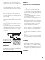 5
5
-
 6
6
-
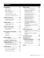 7
7
-
 8
8
-
 9
9
-
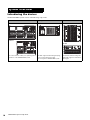 10
10
-
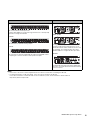 11
11
-
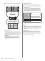 12
12
-
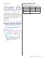 13
13
-
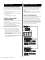 14
14
-
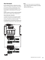 15
15
-
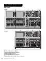 16
16
-
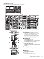 17
17
-
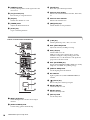 18
18
-
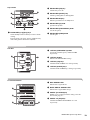 19
19
-
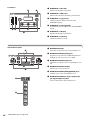 20
20
-
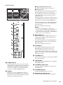 21
21
-
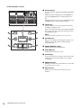 22
22
-
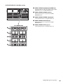 23
23
-
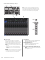 24
24
-
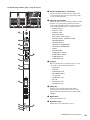 25
25
-
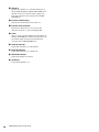 26
26
-
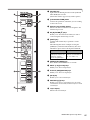 27
27
-
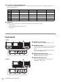 28
28
-
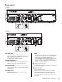 29
29
-
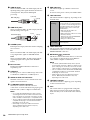 30
30
-
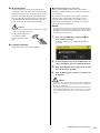 31
31
-
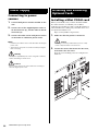 32
32
-
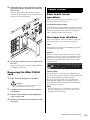 33
33
-
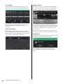 34
34
-
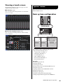 35
35
-
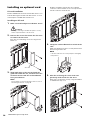 36
36
-
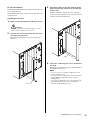 37
37
-
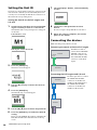 38
38
-
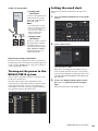 39
39
-
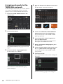 40
40
-
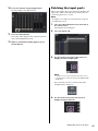 41
41
-
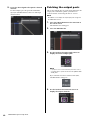 42
42
-
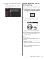 43
43
-
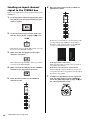 44
44
-
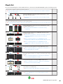 45
45
-
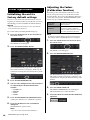 46
46
-
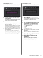 47
47
-
 48
48
-
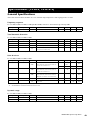 49
49
-
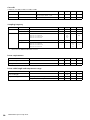 50
50
-
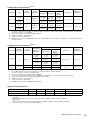 51
51
-
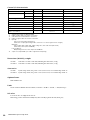 52
52
-
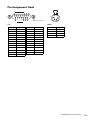 53
53
-
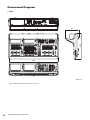 54
54
-
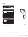 55
55
-
 56
56
-
 57
57
-
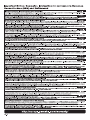 58
58
-
 59
59
-
 60
60


Yamaha PM10 Guía de instalación
- Categoría
- Ecualizadores de audio
- Tipo
- Guía de instalación
en otros idiomas
- français: Yamaha PM10 Guide d'installation
- italiano: Yamaha PM10 Guida d'installazione
- English: Yamaha PM10 Installation guide
- Deutsch: Yamaha PM10 Installationsanleitung
- русский: Yamaha PM10 Инструкция по установке
- Nederlands: Yamaha PM10 Installatie gids
- português: Yamaha PM10 Guia de instalação
- dansk: Yamaha PM10 Installationsvejledning
- polski: Yamaha PM10 Instrukcja instalacji
- čeština: Yamaha PM10 instalační příručka
- svenska: Yamaha PM10 Installationsguide
- 日本語: Yamaha PM10 インストールガイド
- Türkçe: Yamaha PM10 Yükleme Rehberi
- suomi: Yamaha PM10 Asennusohje
- română: Yamaha PM10 Ghid de instalare
Artículos relacionados
-
Yamaha CS-R5 El manual del propietario
-
-
Yamaha V1 El manual del propietario
-
-
-
-
-
-
-