
CONCER T
VIBRAPHONES
YV-4110 YV-3910 YV-3710
YV-2700 YV-2700G YV-520
(YV-3710)
Owner’s Manual
Руководство пользователя
使用手册
사용설명서
Make sure to read the “Safety Precautions” on page 4 and the “PRECAUTIONS” on page 5.
Обязательно прочтите разделы «Меры безопасности» на стр. 8 и «МЕРЫ ПРЕДОСТОРОЖНОСТИ» на стр. 9.
务请阅读第 32 页的“安全注意事项”和第 33 页的“注意事项”。
34 페이지의 “안전 주의사항” 및 35 페이지의 “주의사항” 을 반드시 읽어 주십시오 .
Русский
/ English
한국어
/
中文

2
NAME
PLATE
SPECIAL MESSAGE SECTION
This product utilizes an external power supply (adapter).
DO NOT connect this product to any power supply or
adapter other than one described in the manual, on the
name plate, or specifically recommended by Yamaha.
WARNING:
Do not place this product in a position where
anyone could walk on, trip over, or roll anything over power
or connecting cords of any kind. The use of an extension
cord is not recommended! If you must use an extension
cord, the minimum wire size for a 25" cord (or less) is 18
AWG. NOTE: The smaller the AWG number, the larger
the current handling capacity. For longer extension cords,
consult a local electrician.
This Product should be used only with the components
supplied or; a cart, rack, or stand that is recommended by
Yamaha. If a cart, etc., is used, please observe all safety
markings and instructions that accompany the accessory
product.
SPECIFICATIONS SUBJECT TO CHANGE:
The
information contained in this manual is believed to be
correct at the time of printing. However, Yamaha reserves
the right to change or modify any of the specifications
without notice or obligation to update existing units.
NOTICE:
Service charges incurred due to lack of
knowledge relating to how a function or effect works (when
the unit is operating as designed) are not covered by the
manufacturer’s warranty; and are therefore the owners
responsibility. Please study this manual carefully and
consult your dealer before requesting service.
ENVIRONMENTAL ISSUES:
Yamaha strives to produce
products that are both user safe and environmentally
friendly. We sincerely believe that our products and the
production methods used to produce them, meet these
goals. In keeping with both the letter and the spirit of the
law, we want you to be aware of the following:
Disposal Notice:
Should this Product become damaged
beyond repair, or for some reason its useful life is
considered to be at an end, please observe all local,
state, and federal regulations that relate to the disposal
of products that contain lead, batteries, plastics, etc. If
your dealer is unable to assist you, Please contact Yamaha
directly.
NAME PLATE LOCATION:
The name Plate is located
on the player side of the product. The model number, serial
number, power requirements, etc., are located on this plate.
You should record the model number, serial number, and
the date of purchase in the spaces provided below and
retain this manual as a permanent record of your purchase.
Model
Serial No.
Purchase Date
PLEASE KEEP THIS MANUAL
01_yv4110_ER_1215.indd 2 14/12/25 9:22

3
Information for Users on Collection and Disposal of Old Equipment and used Batteries
Информация для пользователей по сбору и утилизации старой аппаратуры и использованных батареек
These symbols on the products, packaging, and/or accompanying documents mean that used electrical and
electronic products and batteries should not be mixed with general household waste.
For proper treatment, recovery and recycling of old products and used batteries, please take them to applicable
collection points, in accordance with your national legislation and the Directives 2002/96/EC and 2006/66/EC.
By disposing of these products and batteries correctly, you will help to save valuable resources and prevent any
potential negative effects on human health and the environment which could otherwise arise from inappropriate
waste handling.
For more information about collection and recycling of old products and batteries, please contact your local
municipality, your waste disposal service or the point of sale where you purchased the items.
[For business users in the European Union]
If you wish to discard electrical and electronic equipment, please contact your dealer or supplier for further
information.
[Information on Disposal in other Countries outside the European Union]
These symbols are only valid in the European Union. If you wish to discard these items, please contact your
local authorities or dealer and ask for the correct method of disposal.
Note for the battery symbol (bottom two symbol examples):
This symbol might be used in combination with a chemical symbol. In this case it complies with the requirement
set by the Directive for the chemical involved.
Эти знаки на аппаратуре, упаковках и в сопроводительных документах указывают на то, что подержанные электри-
ческие и электронные приборы и батарейки не должны выбрасываться вместе с обычным домашним мусором.
Для правильной обработки, хранения и утилизации старой аппаратуры и использованных батареек по-
жалуйста сдавайте их в соответствующие сборные пункты, согласно вашему национальному законода-
тельству и директив 2002/96/EC и 2006/66/EC.
При правильном отделении этих товаров и батареек, вы помогаете сохранять ценные ресурсы и предот-
вращать вредное влияние на здоровье людей и окружающую среду, которое может возникнуть из-за
несоответствующего обращения с отходами.
За более подробной информацией о сборе и утилизации старых товаров и батареек пожалуйста обращай-
тесь в вашу локальную администрацию, в ваш приёмный пункт или в магазин где вы приобрели эти товары.
[Для представителей компаний в Европейском Союзе]
Если вы хотите избавиться от электрической или электронной аппаратуры, пожалуйста обратитесь к
вашему продавцу или поставщику за полной информацией.
[Информация по утилизации в других странах за пределами Европейского Союза]
Эти знаки действительны только на территории Европейского Союза. Если вы хотите избавиться от этих
предметов, пожалуйста обратитесь в вашу локальную администрацию или продавцу и спросите о пра-
вильном способе утилизации.
Обратите внимание на знак для батареек (два знака на задней стороне):
Этот знак может использоваться в комбинации со знаком указывающим о содержании химикалий. В этом
случае это удовлетворяет требованиям установленными Директивой по использованию химикалий.
01_yv4110_ER_1215.indd 3 14/12/25 9:22

4
Safety Precautions
Please obey the following instructions in order to use your vibraphone in a safe manner.
Particularly in the case of children, a responsible adult should provide proper instruction
on how to properly use and treat the instrument before use.
Icons are used in this “Safety
Precautions” section to pro-
mote the safe use of this
instrument, and to protect
you and others from harm
and property damage. Please
fully understand the meaning
of the icons before reading
the instructions.
In order to prevent fire, electric shock, and injury,
make sure that all precautions described below are obeyed.
About
the
icons
This icon urges caution (includes dangers and warnings).
This icon indicates actions that are prohibited.
This icon indicates special instructions that
should be strictly followed.
For example:
Do not dismantle.
For example:
Unplug the electric
plug from the outlet.
Warning
Disregard of the warnings denoted with this mark and misuse
of the product can lead to death or serious injury.
Before using the vibraphone, please thoroughly read
the following instructions and the Owner’s Manual.
Do not dismantle or modify the vibraphone’s controller
or driver. Doing so can cause fire or electrical shock.
Repairs or part replacement should not be attempted
unless instructions are provided in the manual.
Do not use or store the instrument in any of the fol-
lowing locations. Doing so can cause fire or electrical
shock.
• In places subject to high temperatures (near a
heating device or in direct sunlight, etc.).
• In places where the instrument may be exposed
to moisture (bathroom, on wet floors, etc.) and
excessive humidity.
• In places where the instrument may be exposed
to rain.
• In places with excessive dust.
• In places subject to vibrations.
When using the AC adapter, do not excessively bend
the power cord, or place heavy objects on the cord.
Doing so may damage the cord causing fire or elec-
trical shock.
Do not play or roughhouse around the instrument.
Bumping into the instrument can cause injury. It can
also cause the instrument to overturn. Do not allow
children to play around the instrument.
Do not lean against or climb onto the instrument. Do-
ing so can cause the instrument to overturn resulting
in serious injury.
Never put foreign objects (combustible objects, coins,
wire, etc.) or liquids (water, juice, etc.) in the drive unit.
Doing so can cause fire and electric shock.
If one of the following occurs, turn off the power, unplug
the AC adapter and request repair as soon as possible.
• If the AC adapter or power cord becomes dam-
aged.
• If foreign objects or liquids have gotten into the
drive unit.
• If the drive unit gets wet (rain, etc.).
• If the drive unit operates abnormally or is broken.
Never place the instrument on a sloping or unstable
surface or platform, etc. Doing so can cause the in-
strument to fall over resulting in injury.
When moving the instrument on its casters, only move
across smooth, flat surfaces. Hold the instrument by
its side frames and push forward slowly.
When moving the instrument on its casters,
1. Avoid moving the instrument on surfaces that are
sloped or uneven. The instrument can overturn,
run out of control, and be a danger.
2. Never run with the instrument. The instrument
may become impossible to control and crash into
a wall causing serious injury.
If the instrument must be lifted or carried, do so with
two or more people using both hands to lift it by the
side frames.
* Vibraphone weight
YV-4110: 64kg
YV-3910: 61kg
YV-3710: 60kg
YV-2700/2700G: 57kg
YV-520: 31kg
01_yv4110_ER_1215.indd 4 14/12/25 9:22

5
●
Do Not Use Outdoors
Avoid using the instrument outdoors. Avoid exposure to rain or
moisture.
●
Handling
• Do not use hard orchestra bell mallets or other hard objects
on your vibes. The resulting dents or scratches in the tone
bars could impair the sound.
• Rough handling of the controller and/or the driver may cause
damage to the internal circuitry.
●
Moving and Transporting the Instrument
• Move the instrument carefully to avoid shocks. Before moving
the instrument, make sure that the AC adapter is disconnect-
ed and the caster brakes are released. Also make sure to lift
the instrument slightly when moving over rough surfaces.
• When the instrument must be transported to a different loca-
tion make sure to fully disassemble it, taking care to pack
each component properly. Disassembly steps are in the op-
posite order of assembly.
●
Maintenance
The tone bars should be polished from time to time using a
soft and dry cloth or silicone cloth. Stains that cannot be re-
moved with a dry cloth may be wiped off using a small amount
of ethyl alcohol. Never use thinner or benzene or a wet cloth
for cleaning purposes.
PRECAUTIONS
Please read the following instructions carefully before using your vibes.
Assembly Cautions
• When assembling/disassembling the instrument, make sure
to follow the procedure outlined in this manual. Assembly in
the wrong order may impair the performance and functional-
ity of the instrument or cause noise.
• Make sure to adjust the wire clip positions after assembly.
(YV-4110/3910/3710: P. 23)
• Height adjustment of the striking surface (YV-4110/3910
/3710: P. 24, YV-2700/2700G/520: P. 31) should be per-
formed by
AT LEAST 2 PERSONS
.
• After final adjustment of the legs the fixing screws must
be tightened securely to prevent loosening. Looseness
may cause the instrument to shift during performance and
can also cause noise and other problems. Retighten the
screws from time to time.
●
Keep This Manual for Future Reference
After reading, make sure to keep the manual in a safe place.
Safety Precautions
Caution
Disregard of the warnings denoted with this mark, or misuse of
the product can result in injury or property damage.
Do not use the instrument in locations with poor ven-
tilation.
Never pull on the cord when disconnecting the AC
adapter from the outlet. Always hold the AC adapter
when connecting or disconnecting the power.
Always disconnect the AC adapter from the outlet
when the instrument is not used for any extended pe-
riod of time.
Always use an AC adapter that meets YAMAHA
specifications. The use of any other AC adapter may
cause damage.
Never place your hands or feet underneath the pedal.
Doing so can result in pinched hands or feet.
Never touch the rotating fans. Doing so can result in
pinched fingers, etc.
Never use the mallets for anything other than playing
the instrument. Doing so can result in injury or acci-
dents. Do not allow children to use the mallets in any
way that may pose a danger to themselves or others.
Lock the stoppers on the casters when the instrument
is not in use.
When adjusting the playing surface height (described
on page 29), make sure that the procedure is per-
formed by at least two persons. Attempting to adjust
the height alone can result in the instrument over-
turning and create a danger.
Never touch the areas shown below when adjusting
the height. Doing so can result in pinched hands.
Make sure to hold the side frame when making
height adjustments.
Do not touch these
areas when adjusting
the height.
Tighten bolts securely after determining the desired
height. Using the instrument with loose bolts can
result in the instrument collapsing, noise, or other
troubles. Tighten the bolts occasionally.
Side Frame
01_yv4110_ER_1215.indd 5 14/12/25 9:22

6
Précautions à observer
Il est important que vous respectiez les instructions ci-dessous pour utiliser votre vibraphone en toute sécurité.
Plus particulièrement dans les cas où des enfants sont impliqués, un adulte responsable doit leur expliquer com-
ment utiliser et manipuler l’instrument avant de les laisser s’en servir.
Des icônes sont utilisées dans
cette section pour rendre plus
claires les instructions de sécurité
permettant d’éviter les risques de
blessure et de dégâts matériels.
Veuillez bien lire les consignes et
comprendre le sens de chaque
icône avant de lire le reste de ce
mode d’emploi.
Pour éviter tout risque d’incendie, de décharge électrique ou de blessure,
veillez à l’observation de toutes les précautions ci-dessous.
À
propos
des
icônes
Cette icône vous recommande d’être attentif (et peut signaler des
dangers et avertissements)
Cette icône signale des
actions interdites.
Cette icône signale des
instructions spéciales qui
doivent absolument être suivies.
Exemple:
Ne pas démonter.
Exemple:
Débrancher le cordon
d’alimentation de la prise secteur.
Avertissement
Si vous négligez les avertissements signalés par ce symbole et si vous utilisez
l’instrument de manière incorrecte, il peut en résulter mort d’homme ou blessures.
Avant d’utiliser le vibraphone, lisez attentivement les
instructions ci-dessous et l’intégralité du mode d’em-
ploi.
Ne démontez pas et ne cherchez pas à modifier le
contrôleur ou le boîtier d’entraînement du vibrapho-
ne. Vous risqueriez de subir une décharge électrique.
Ne tentez pas de réparer ou de remplacer des pièces
en l’absence d’instructions correspondantes dans ce
manuel.
N’utilisez pas et ne stockez pas l’instrument dans un
des environnements ci-dessous; vous risqueriez de
causer un incendie ou de subir une décharge électri-
que.
• Lieux soumis à des températures élevées (à côté
d’un radiateur, exposé au soleil, etc.).
• Lieux soumis une humidité excessive (salle de
bains, sol mouillé, cave, etc.).
• Lieux exposés à la pluie.
• Lieux exposés à la poussière de façon excessive.
• Lieux soumis à des vibrations.
Lorsque vous utilisez l’adaptateur secteur, ne tordez
pas le cordon d’alimentation de façon excessive et
ne placez pas d’objet lourd sur ce cordon. En cas
d’inobservation de ces consignes, le cordon pourrait
causer un incendie ou vous faire subir une décharge
électrique.
Ne jouez pas, ne soyez pas turbulent à proximité de
l’instrument. Vous pourriez vous y cogner et vous
blesser. L’instrument pourrait également tomber. Éloi-
gnez les enfants de l’instrument.
Ne vous appuyez pas sur l’instrument et ne montez
pas dessus. Il pourrait tomber et blesser quelqu’un.
Ne placez pas d’objet étranger (objets combustibles,
pièces de monnaie, fil électrique, etc.) ou de liquide
(eau, jus de fruit, etc.) sur le boîtier d’entraînement.
Vous risqueriez de causer un incendie ou de subir
une décharge électrique.
Si l’un des événements suivants se produits, mettez
l’instrument hors tension, débranchez l’adaptateur
secteur de la prise de courant et sollicitez une inter-
vention dès que possible.
• Si l’adaptateur secteur ou le cordon d’alimentation
est endommagé.
• Si des objets étrangers ou des liquides ont pénétré
dans le boîtier d’entraînement.
• Si le boîtier d’entraînement est mouillé (par la
pluie, etc.)
• Si le boîtier d’entraînement fonctionne de façon
anormale ou est cassé.
Ne placez en aucun cas l’instrument sur un plan in-
cliné ou instable. Il pourrait tomber ou se retourner et
blesser quelqu’un.
Lorsque vous déplacez l’instrument en le faisant rouler
sur ses roulettes, ne le déplacez que sur des surfaces
planes et lisses. Tenez l’instrument par son châssis et
poussez doucement.
Lorsque vous déplacez l’instrument sur ses roulettes :
1. Évitez de le faire passer sur des surfaces en pen-
te, inégales ou sur du gravier. Il pourrait s’effondrer
ou vous échapper.
2. Ne courrez pas avec l’instrument. Ce dernier
pourrait devenir impossible à arrêter, heurter un
mur et être à l’origine de blessures graves.
Si vous devez soulever ou porter l’instrument, soyez
au moins deux personnes en utilisant les deux mains
pour le soulever par les côtés du châssis.
* Poids du vibraphone
YV-4110: 64 kg
YV-3910: 61 kg
YV-3710: 60 kg
YV-2700/2700G: 57 kg
YV-520: 31 kg
01_yv4110_ER_1215.indd 6 14/12/25 9:22

7
Précautions à observer
Attention
Si vous négligez les avertissements signalés par ce symbole, vous pourriez infliger des
blessures ou des handicaps à des personnes ou causer la perte de biens matériels.
N’utilisez pas l’instrument dans des endroits mal ven-
tilés.
Ne tirez jamais sur le cordon d’alimentation pour dé-
brancher l’adaptateur secteur de la prise de courant.
Tenez toujours l’adaptateur lorsque vous le branchez
et le débranchez.
Débranchez toujours l’adaptateur secteur de la prise
de courant lorsque l’instrument n’est pas utilisé pen-
dant une période prolongée.
Utilisez toujours un adaptateur secteur conforme aux
spécifications YAMAHA. L’utilisation d’un autre adap-
tateur secteur pourrait causer des dommages.
Ne placez jamais les mains ou les pieds sous la pé-
dale. Vous risqueriez de vous pincer les pieds ou les
doigts.
Ne touchez jamais les ailettes tournantes. Vous pour-
riez vous blesser les doigts.
N’utilisez en aucun cas les baguettes pour autre cho-
se que pour jouer de l’instrument. Vous pourriez vous
blesser ou causer un accident. Ne laissez pas les
enfants utiliser ces baguettes de façon dangereuse
pour eux ou pour d’autres.
Lorsque l’instrument n’est pas utilisé, bloquez les
freins des roulettes.
Lors du réglage en hauteur de l’instrument, veillez
à effectuer la procédure à deux personnes. Toute
tentative de réglage par une seule personne pourrait
provoquer le renversement de l’instrument et créer
un danger.
Ne touchez jamais les zones illustrées ci-dessous
lorsque vous effectuez le réglage en hauteur. Vous
pourriez vous pincer les doigts. Veillez à tenir l’instru-
ment par les côtés.
Serrez fermement les vis après avoir déterminé la
hauteur souhaitée. Si les vis sont mal serrées, l’ins-
trument peut s’écrouler, faire du bruit ou être la cause
d’autres désagréments. De temps à autre, resserrez
ces vis.
Ne touchez pas ces
zones lors du réglage
en hauteur.
Montant latéral
Information concernant la Collecte et le Traitement des piles usagées et des déchets d’équipements
électriques et électroniques
Les symboles sur les produits, l’emballage et/ou les documents joints signient que les produits électriques ou
électroniques usagés ainsi que les piles ne doivent pas être mélangés avec les déchets domestiques habituels.
Pour un traitement, une récupération et un recyclage appropriés des déchets d’équipements électriques et
électroniques et des piles usagées, veuillez les déposer aux points de collecte prévus à cet effet, conformé-
ment à la réglementation nationale et aux Directives 2002/96/EC et 2006/66/EC.
En vous débarrassant correctement des déchets d’équipements électriques et électroniques et des piles
usagées, vous contribuerez à la sauvegarde de précieuses ressources et à la prévention de potentiels effets
négatifs sur la santé humaine qui pourraient advenir lors d’un traitement inapproprié des déchets.
Pour plus d’informations à propos de la collecte et du recyclage des déchets d’équipements électriques et élec-
troniques et des piles usagées, veuillez contacter votre municipalité, votre service de traitement des déchets ou
le point de vente où vous avez acheté les produits.
[Pour les professionnels dans l’Union Européenne]
Si vous souhaitez vous débarrasser des déchets d’équipements électriques et électroniques veuillez contacter
votre vendeur ou fournisseur pour plus d’informations.
[Information sur le traitement dans d’autres pays en dehors de l’Union Européenne]
Ces symboles sont seulement valables dans l’Union Européenne. Si vous souhaitez vous débarrasser de
déchets d’équipements électriques et électroniques ou de piles usagées, veuillez contacter les autorités locales
ou votre fournisseur et demander la méthode de traitement appropriée.
Note pour le symbole “pile” (deux exemples de symbole ci-dessous):
Ce symbole peut être utilisé en combinaison avec un symbole chimique. Dans ce cas il respecte les exigences
établies par la Directive pour le produit chimique en question.
01_yv4110_ER_1215.indd 7 14/12/25 9:22

8
Меры безопасности
Для обеспечения безопасности использования Вашего вибрафона, пожалуйста, выполняйте приведенные ниже инструкции.
В частности, для детей перед началом использования инструмента следует провести надлежащий инструктаж
по использованию и уходу за вибрафоном.
Знаки, используемые в разделе
«Меры безопасности», предназна-
чены для обеспечения безопасно-
сти эксплуатации данного инстру-
мента, а также для защиты Вас и
других от травм и повреждения
имущества.
Прежде чем прочесть инструкцию,
изучите значение каждого знака.
Во избежание возгорания, поражения электрическим током или получения травмы убедитесь,
что соблюдаются все меры предосторожности, приведенные ниже.
О знаках
Данный знак указывает на необходимость соблюдения осторожности
(включая опасности и предупреждения).
Данный знак означает запрещенные
действия.
Данный знак означает специальные
инструкции, которые следует строго
выполнять.
Например: Не разбирать.
Например:
Отсоедините штекер электропи-
тания от настенной розетки.
Предупреждение
Игнорирование предупреждений с данным знаком и неправильное исполь-
зование данного изделия могут привести к смерти или серьезной травме.
Перед использованием вибрафона, пожалуйста, полностью
прочтите инструкции, приведенные ниже, и руководство
пользователя.
Не разбирайте и не модифицируйте контроллер или привод
вибрафона. Это может вызвать возгорание или поражение
электрическим током.
Не следует пытаться самостоятельно проводить ремонт или
замену запчастей, если в настоящем руководстве не приве-
дены такие указания.
Не используйте и не храните инструмент в следующих ме-
стах. Это может вызвать возгорание или поражение электри-
ческим током.
•
В местах с высокой температурой (вблизи нагреватель-
ного оборудования или в местах воздействия прямого
солнечного света и т.п.).
•
В местах, где инструмент подвержен воздействию влаги
(ванная комната, на мокром полу и т.п.) и в местах с чрез-
мерной влажностью.
•
В местах, где инструмент может попасть под дождь.
•
В местах с чрезмерной запыленностью.
•
В местах, подверженных вибрациям.
При использовании адаптера переменного тока не скручи-
вайте шнур электропитания и не ставьте на шнур тяжелые
предметы. Это может повредить шнур и вызвать возгорание
или поражение электрическим током.
Нельзя играть в игры или толкаться возле инструмента. На-
толкнувшись на инструмент, Вы можете получить травму.
Это также может вызвать переворачивание инструмента. Не
позволяйте детям играть в игры возле инструмента.
Не наклоняйте инструмент и не взбирайтесь на него сверху.
Это может вызвать переворачивание инструмента и причи-
нить Вам травму.
Не вставляйте в узел привода посторонние предметы (воспла-
меняемые предметы, монеты, проводку и т.п.) и не наливайте
жидкости (воду, сок и т.п.). Это может вызвать возгорание и
поражение электрическим током.
При возникновении приведенных ниже ситуаций отключите
питание, отсоедините адаптер переменного тока и как можно
скорее обратитесь за ремонтом.
•
Если адаптер переменного тока или шнур электропитания
поврежден.
•
Если в узел привода попали посторонние предметы или
жидкости.
•
При намокании узла привода (под дождем и т.п.).
•
Если узел привода работает неправильно или поломан.
Никогда не размещайте инструмент на наклонной, неустойчи-
вой и т.п. площадке. Это может привести к падению инстру-
мента и причинению Вам травмы.
При перемещении инструмента на его роликах перемещайте
его только по гладким плоским поверхностям. Держите ин-
струмент за края рамы и медленно толкайте его вперед.
При перемещении инструмента на его роликах:
1. Старайтесь не перемещать инструмент по наклонным или
неустойчивым поверхностям. Инструмент может пере-
вернуться, выйти из-под контроля и стать источником
опасности.
2. Никогда не бегите с инструментом. Может случиться так,
что инструментом нельзя будет управлять, и столкнове-
ние инструмента со стеной приведет к тяжелой травме.
Если требуется поднять или перенести инструмент, выполняйте
это вдвоем, поднимая инструмент обеими руками за края рамы.
* Масса вибрафона
YV-4110: 64 кг
YV-3910: 61 кг
YV-3710: 60 кг
YV-2700/2700G: 57 кг
YV-520: 31 кг
01_yv4110_ER_1215.indd 8 14/12/25 9:22

9
●
Не используйте вне помещения
Избегайте использования инструмента вне помещения. Не подвергайте
инструмент воздействию дождя или влаги.
●
Обращение с инструментом
•
Не используйте для игры на вибрафоне колотушки для оркестровых
колоколов или другие твердые предметы. Образовавшиеся вмятины
или царапины на тоновых пластинах могут нарушить звучание.
•
Неосторожное обращение с контроллером и/или приводом может
привести к повреждению встроенной печатной платы.
●
Перемещение и транспортировка инструмента
•
Перемещайте инструмент осторожно, избегая ударов. Перед пере-
мещением инструмента убедитесь, что отсоединили адаптер пере-
менного тока, а также не забудьте отпустить тормоза на роликах.
Также не забывайте приподнимать инструмент при его перемещении
по неровным поверхностям.
•
Если инструмент требуется транспортировать в другое место, обяза-
тельно полностью разберите его, упаковав при этом каждую деталь над-
лежащим образом. Разборка выполняется в порядке, обратном сборке.
●
Уход за инструментом
Время от времени тоновые пластины следует полировать чистой и су-
хой тканью или силиконовой тканью. Пятна, которые не удается устра-
нить сухой тканью, можно удалить с помощью небольшого количества
этилового спирта. Никогда не используйте для очистки растворитель
или бензин либо влажную ткань.
МЕРЫ ПРЕДОСТОРОЖНОСТИ
Перед использованием вибрафона, пожалуйста, внимательно прочтите следующие инструкции.
Меры предосторожности при сборке
•
Во время сборки/разборки инструмента обязательно соблюдайте
процедуры, приведенные в данном руководстве. Сборка в непра-
вильном порядке может привести к нарушению характеристики
и функции инструмента либо вызвать появление шумов.
•
Убедитесь в том, что после сборки отрегулировали положение
скобы крепления электропроводки. (Для модели YV-4110/3910/
3710: см. стр. 23)
•
Регулировку высоты ударной поверхности (для модели YV-4110/
3910/3710: см. стр. 24, для модели YV-2700/2700G/520: см. стр.
31) следует выполнять,
ПО МЕНЬШЕЙ МЕРЕ, ВДВОЕМ
.
•
После завершения регулировки ножек фиксирующие винты сле-
дует надежно затянуть во избежание их ослабления. Ослабление
может привести к перемещению инструмента во время игры, а
также вызывать шумы и создавать другие проблемы. Время от
времени подтягивайте винты.
●
Сохраните данное руководство для будущего исполь-
зования
После прочтения храните руководство в надежном месте.
Меры безопасности
Внимание
Игнорирование предупреждений с данным знаком и неправильное использование
данного изделия могут привести к травме или повреждению имущества.
Не используйте инструмент в местах с плохой вентиляцией.
Никогда не тяните за шнур, отсоединяя адаптер переменного
тока от розетки. Всегда придерживайте адаптер переменного
тока при подключении или отключении электропитания.
Всегда отсоединяйте адаптер переменного тока от розетки,
если не будете использовать инструмент в течение длитель-
ного периода времени.
Всегда используйте адаптер переменного тока, который
соответствует техническим характеристикам YAMAHA. Ис-
пользование какого-либо другого адаптера может привести к
повреждению.
Никогда не помещайте руки или ноги под педаль.
Это может привести к тому, что Вы прищемите руки или ноги.
Никогда не прикасайтесь к вращающимся лопастям резона-
торов. Это может прищемить пальцы и т.п.
Никогда не используйте ударные палочки ни для чего друго-
го, кроме как для игры на инструменте. Это может привести
к травме или несчастным случаям. Не позволяйте детям
использовать ударные палочки ни для чего, что может пред-
ставлять опасность для них или для других людей.
Блокируйте ролики, если не будете использовать инстру-
мент.
При регулировке высоты игровой поверхности (описано на
стр. 29) убедитесь, что процедура выполняется, по меньшей
мере, двумя лицами. Попытка регулировки высоты в одиноч-
ку может вызвать переворачивание инструмента и может
представлять собой опасность.
При регулировке высоты никогда не прикасайтесь к местам,
показанным ниже. Это может привести к прищемлению рук.
При выполнении регулировок высоты убедитесь, что удержи-
ваете боковую раму.
При регулировке высоты
не касайтесь этих мест.
Определив нужную высоту, надежно затяните винты. Исполь-
зование инструмента с ослабленными винтами может при-
вести к поломке инструмента, шуму или другим проблемам.
Время от времени затягивайте винты.
Боковая рама
01_yv4110_ER_1215.indd 9 14/12/25 9:22

10
Nomenclature /
Обозначения
r e w q
* The illustration shows model YV-3710.
*
На рисунке приведена модель YV-3710.
Pedal Stay
Опора педали
Rail No. 1
Перекладина №1
Frame End (Large)
Конец рамы (большой конец)
Resonators
(Natural Tone Side)
Резонаторы
(со стороны натуральных звуков)
Leg (Large)
Ножка (большая)
Natural Tone Bars
Тоновые пластины натуральных звуков
Accidental Tone Bars
Тоновые пластины дополнительных звуков
Controller
Контроллер
Fan Belt
Ремень привода лопастей резонаторов
Frame End (Small)
Конец рамы (малый конец)
Pedal
Педаль
Caster
Ролик
AC Adapter
Адаптер переменного тока
Leg (Small)
Ножка (малая)
Driver
Привод
Slide Leg
Выдвижная ножка
Resonators
(Accidental Tone Side)
Резонаторы (со стороны
дополнительных звуков)
Slant Shaft
Наклонная опора
■
Vibes Drive Unit /
Узел привода вибрафона
●
Controller (Player Side)
Контроллер (со стороны исполнителя)
q
POWER Switch
Turns the power on and off.
w
MOTOR SPEED Slider
Controls the fan rotation speed.
e
LED Indicator
Lights when the power is turned on
and flashes while the fan is rotating.
r
START/STOP Button
Starts and stops fan rotation.
t
DC 12-15V IN Jack
y
MOTOR OUT Terminal
u
MOTOR IN Terminal
i
8P DIN Cable
o
AC Adapter
●
Controller (Right Side
Контроллер (с правой стороны)
●
Driver (Player Side)
Привод
(со стороны исполнителя)
q
Выключатель POWER
Включает и выключает питание.
w
Ползунок MOTOR SPEED
Управляет частотой вибрато.
e
Светодиодный индикатор
Загорается при включении питания и ми-
гает при вращении лопастей резонаторов.
r
Кнопка START/STOP
Запускает и останавливает вращение ло-
пастей резонаторов.
t
Гнездо DC 12-15V IN
y
Разъем MOTOR OUT
u
Разъем MOTOR IN
i
Кабель 8P DIN
o
Адаптер переменного тока
YV-4110/3910/3710/2700/2700G/520
y
i
t
u
o
01_yv4110_ER_1215.indd 10 14/12/25 9:22

11
Confirmation of packing contents
Проверка содержимого комплекта
q
Natural Tone Bars x 1
q
Тоновые пластины натуральных звуков x 1
w
Accidental Tone Bars x 1
w
Тоновые пластины дополнительных
звуков x 1
e
Resonators (Natural Tone Side) x 1
e
Резонаторы (со стороны натуральных
звуков) x 1
r
Resonators (Accidental Tone Side) x 1
r
Резонаторы (со стороны дополнительных
звуков) x 1
!3
AC Adapter x 1
!3
Адаптер переменного тока
x 1
!4
Synchro Belt (Fan Belt) x 2
!4
Синхронизирующий ремень
(ремень
привода лопастей резонаторов) x 2
!6
Controlle
r x 1
!6
Контроллер
x 1
!7
8P DIN Cable x 1
!7
Кабель 8P DIN x 1
!5
Driver x 1
!5
Привод
x 1
!1
Leg (L
arge) x 1
!
1
Ножка (большая) x 1
!2
Leg (Small) x 1
!2
Ножка (малая) x 1
u
Rail (1) : Player Side x 1
u
Перекладина (1) :
Сторона исполнителя x 1
i
Rail (2) : Player Side x 1
i
Перекладина (2) :
Сторона исполнителя x 1
o
Rail (3) : Audience Side x 1
o
Перекладина (3) :
Сторона аудитории x 1
!0
Rail (4) : Audience Side x 1
!0
Перекладина (4) :
Сторона аудитории x 1
y
Pedal Stay x 1
y
Опора педали x 1
t
Sustain Damper x 1
t
Демпфер x 1
Vibes Drive Unit: YVM-300
Узел привода вибрафона: YVM-300
Name Plate
Фирменная табличка
Posts (Larger number
than parts
o
and
!0
)
Штыри (большее количество,
чем на деталях
o
и
!0
)
Rail Clamp
Фиксатор перекладины
Posts
Штыри
Rail Clamp
Фиксатор перекладины
Posts
Штыри
YAMAHA Logo
Логотип YAMAHA
В картонной коробке, в которой поставляется Ваш YV-4110/
3910/3710, должны быть в наличии компоненты, показанные
ниже.
Перед сборкой инструмента убедитесь в наличии всех пере-
численных компонентов.
* В случае если какой-либо компонент отсутствует, пожалуйста, об-
ратитесь в магазин, где был приобретен инструмент.
The shipping carton of your YV-4110/3910/3710 should
contain the parts shown below.
are included as listed.
* In the event that a part is missing, please contact the shop
where the instrument was purchased.
YV-4110/3910/3710
* May not be included depending on your particular area.
* Может не входить в комплект поставки в вашем регионе.

12
Confirmation of packing contents /
Проверка содержимого комплекта
●
Rails
The rails fold in from the center.
●
Перекладины
Перекладины складываются посередине.
Loosen
Ослабить
●
Resonators
Both resonators divide into two sections.
Loosen both bolts and separate left and right sections.
* When assembling the resonators, make sure that
the pin and notch are properly aligned.
●
Резонаторы
Оба резонатора разделены на две секции.
Ослабьте оба болта и разъедините левую и правую секции.
* При сборке резонаторов убедитесь в том, что правиль-
но совместили штырь и прорезь.
●
Sustain Damper
The sustain damper divides into 2 sections.
Loosen the bolt and separate left and right sections.
●
Демпфер
Демпфер разделен на 2 секции.
Ослабьте болт и разъедините левую и правую секции.
Loosen
Ослабить
●
Pedal Stay
The pedal stay divides into left and right sections and the
pedal itself.
Loosen the 2 wing nuts and remove the
stays from the pedal attachment.
●
Опора педали
Опора педали разделяется на левую, правую секцию и
саму педаль.
Ослабьте 2 барашковые гайки и снимите опоры с кре-
пления педали.
Loosen
Ослабить
Notch
Прорезь
Pin
Штырь
■
Разборные и складные детали
Большие детали модели YV-4110/3910/YV-3710 являются раз-
борными и складными. Компактные размеры инструмента в
разобранном виде облегчают транспортировку и хранение
при минимальном пространстве.
■
Dividable Parts and Collapsible Parts
The YV-4110’s/3910’s/YV-3710’s large parts are
designed to either divide or collapse. When the in-
strument is broken down, its compact size makes it
easy to transport and storage requires a minimum
amount of space.
YV-4110/3910/3710
01_yv4110_ER_1215.indd 12 14/12/25 9:22

13
For safety, assembly should be performed by at least 2
persons in a location with sufficient space.
We recommend to you to assemble the instrument on
a soft rug or carpet.
z
Connect the large and the small leg using
the reinforcement stay and pedal stay.
* Before proceeding, make sure that the slide leg fixing
bolts of the large and small leg are securely fastened.
Slide Leg
Fixing Bolt
Фиксирующий
винт сдвижной
ножки
Slide Leg
Fixing Bolt
Фиксирующий
винт сдвижной
ножки
Slide Leg
Fixing Bolt
Фиксирующий
винт сдвижной
ножки
Slide Leg
Сдвижная ножка
The tip of each slide leg fixing bolt must be
tightly seated in one of the slide leg notches.
Наконечник каждого фиксирующего винта сдвиж-
ной ножки должен надежно находиться в одной из
прорезей в сдвижной ножке.
Slide Leg Fixing Bolt
Фиксирующий винт
сдвижной ножки
Leg (Large)
Ножка (большая)
Leg (Small)
Ножка (малая)
High Sound Side
Сторона высоких частот
Low Sound Side
Сторона низких частот
Leg (Small)
Ножка (малая)
Leg (Large)
Ножка (большая)
1-1
Place the large leg, small leg, pedal stay so that after
assembly each part will be positioned as illustrated.
Slant Shaft
Наклонная опора
Pedal
Педаль
Pedal Stay
Опора педали
Align flat surfaces.
Flat surface should face
player side.
Выровняйте плоские поверх-
ности.
Плоская поверхность должна
быть направлена в сторону
исполнителя.
Audience Side
Сторона аудитории
Player Side
Сторона исполнителя
Assembly /
Сборка
z
Соедините большую и малую ножки с помо-
щью скрепляющей балки и опоры педали.
* Перед переходом к следующему шагу убедитесь в том, что
натяжные болты большой и малой сдвижных ножек надежно
затянуты.
1-1
Расположите большую ножку, малую ножку, опору педали
таким образом, чтобы после сборки каждая деталь была
расположена, как показано на рисунке.
В целях безопасности инструмент должны собирать, по мень-
шей мере, два человека в помещении с достаточным свобод-
ным пространством
.
Рекомендуется собирать инструмент на мягком ковре или
ковровом покрытии.
YV-4110/3910/3710
01_yv4110_ER_1215.indd 13 14/12/25 9:22

14
1-2 Insert the pedal stay with its notch facing up into the
lower joint of the large leg as far as it will go (aligning
the notch with the fixing bolt) and tighten the fixing
bolt securely.
* The hole next to the notch serves as a reference for
the correct insertion position.
1-3 Connect the other ends of the pedal stay with the
small leg in the same way.
Leg (Large)
Ножка (большая)
Tighten
Затянуть
Pedal Stay
Опора педали
Notch
Прорезь
Reference Hole
Базовое отверстие
Pedal Stay
Опора педали
Notch
Прорезь
Leg (Large)
Ножка (большая)
Fixing Bolt
Фиксирующий винт
1-4 Loosen the slant shaft bolt, extend the shaft and in-
sert the shaft end into the leg joint.
With the notch aligned with the fixing bolt (the same
as in the pedal stay assembly) tighten the fixing bolt
securely.
1-5 Connect the other side slant shaft with the small leg
in the same way.
Leg Joint
Шарнир ножки
Slant Shaft Bolt
Болт наклонной опоры
Notch
Прорезь
1-2
Вставьте опору педали прорезью вверх в нижний шарнир
ножки с большого конца как можно дальше (совместите
прорезь с фиксирующим болтом) и надежно затяните фик-
сирующий болт.
* Отверстие рядом с прорезью служит в качестве направ-
ляющей для правильной установки.
1-3
Соедините другие концы опоры педали с малой ножкой та-
ким же образом.
1-4
Ослабьте болт наклонной опоры, выдвиньте опору и вставь-
те ее конец в шарнир ножки.
Совместив прорезь с натяжным болтом (так же, как и при
сборке опоры педали), надежно затяните натяжной болт.
1-5
Подсоедините другую сторону наклонной опоры к малой
ножке таким же образом.
Assembly /
Сборка
YV-4110/3910/3710
01_yv4110_ER_1215.indd 14 14/12/25 9:22

15
Assembly /
Сборка
YV-4110/3910/3710
x
Insert the rails (1) through (4) into the legs.
2-1 First, insert rail (2).
* Do not insert the rail one side at a time, but at first
alternately push in the left and right sides little by
little, after which the rail can be pushed down until it
stops.
2-2 Next, securely insert the rails (3), (1) and (4), in this
order.
Player Side
Сторона исполнителя
Low Sound Side
Сторона низких частот
Rail Clamp
Фиксатор перекладины
Rail (1): With name plate. The name plate side facing the player.
Перекладина (1): С фирменной табличкой. Стороной с фирменной табличкой в направлении исполнителя.
Rail (2): With rail clamp and more posts than rails (3) and (4). The clamp side facing the player.
Перекладина (2): С фиксатором перекладины и количеством штырей больше, чем на перекладинах (3) и (4).
Стороной фиксатора к исполнителю.
Rail (3): With rail clamp and less posts than rail (2). The clamp side facing the audience.
Перекладина (3): С фиксатором перекладины и количеством штырей меньше, чем на перекладине (2).
Стороной фиксатора к аудитории.
Rail (4): With YAMAHA logo. Logo side facing the audience.
Перекладина (4): С логотипом YAMAHA. Сторона с логотипом направлена на аудиторию.
Post
Штырь
High Sound Side
Сторона высоких частот
Audience Side
Сторона аудитории
Name Plate
Фирменная табличка
* The illustration shows model YV-3710.
* На рисунке приведена модель YV-3710.
x
Вставьте перекладины (1) в отверстия (4) в
ножках.
2-1
Сначала вставьте перекладину (2).
* Не вставляйте перекладину только одной стороной, а
сначала по очереди понемногу вставляйте правую и левую
стороны, после чего перекладину можно вставлять до упо-
ра.
2-2
Затем плотно вставьте перекладины (3), (1) и (4), в таком же
порядке.
01_yv4110_ER_1215.indd 15 14/12/25 9:22

16
c
Attach the sustain damper.
3-1
z
Turn the fixing bolt (damper arm axle) of the
damper arm attachment counterclockwise until the
axle has fully disappeared in the attachment hole.
x
Align the damper arm hole with the damper arm
axle.
c
Turn the fixing bolt of the damper arm attachment
clockwise to insert the damper arm axle into the
sustain damper arm.
1
Damper Arm Axle
Ось ручки демпфера
Fixing Bolt
Натяжной болт
2
Sustain Damper Arm
Ручка опорного демпфера
3
Screw in to insert damper arm axle
Завинтите для того, чтобы вставить
ось ручки демпфера
Damper Arm Attachment
Крепление ручки демпфера
Sustain Damper Arm
Ручка опорного демпфера
Sustain Damper
Демпфер
Sustain Damper Arm
Ручка опорного демпфера
Damper Arm Attachment
Крепление ручки демпфера
Turn fixing bolt to
retract the axle.
Затяните натяжной болт
для втягивания оси.
Sustain Damper Arm
Ручка опорного демпфера
Damper Arm Axle
Ось ручки демпфера
c
Прикрепите Демпфер.
3-1
z
Вращайте натяжной болт (ось ручки демпфера) на кре-
плении ручки демпфера против часовой стрелки, пока
ось не исчезнет полностью в крепежном отверстии.
x
Совместите отверстие в ручке демпфера с осью для
ручки демпфера.
c
Вращайте натяжной болт ручки демпфера по часовой
стрелке, чтобы вставить ось для ручки демпфера в руч-
ку опорного демпфера.
Assembly /
Сборка
YV-4110/3910/3710
01_yv4110_ER_1215.indd 16 14/12/25 9:22

17
3-2 Align the holes in both ends of the damper spring
stopper with the protrusions of the fittings on the bot-
tom surfaces of rails (2) and (3) and insert.
Rail (2)
Перекладина (2)
Protrusion
Выступ
Damper Spring Stopper
Пружинный стопор демпфера
Bottom View
Вид снизу
Protrusion
Выступ
Damper
Spring Stopper
Пружинный сто-
пор демпфера
OK
Правильно
3-2
Совместите отверстия в обоих концах пружинного стопора
демпфера с выступами в деталях на обеих поверхностях
перекладин (2) и (3) и вставьте.
3-3
z
Loosen the center rod fixing bolts to extend the
center rod.
x
Connect the center rod with the fitting of the rod
connector by firmly holding the center rod while
turning the rod connector.
c
Tighten the rod connector until it stops, and then
secure with the lock nut.
Rod Connector
Разъем центрального стержня
Pedal Rod
Педальный стержень
Knurled Part
Рифленая деталь
c
Secure
c
Закрепить
x
Turn (screw on)
x
Вращайте
(завинчивайте)
Center Rod Fixing Bolt
Натяжной болт центрального стержня
z
Loosen
z
Ослабить
Lock Nut
Контргайка
z
Loosen
z
Ослабить
Center Rod
Центральный стержень
3-3
z
Ослабьте натяжные болты центрального стержня, чтобы
выдвинуть центральный стержень.
x
Соедините центральный стержень с разъемом, надежно
удерживая центральный стержень и вращая разъем.
c
Затяните разъем стержня до упора, а затем закрепите
его контргайкой.
Assembly /
Сборка
YV-4110/3910/3710
01_yv4110_ER_1215.indd 17 14/12/25 9:22

18
v
Attach the resonators.
4-1 Insert the resonators from underneath the frame and
rest the high sound side and then the low sound side
onto the resonator holders (rubber).
* Make sure not to confuse the natural tone side and
accidental tone side resonators.
* Take care not to bump the resonators against the
legs etc.
x
z
Low Sound Side
Сторона низких частот
High Sound Side
Сторона высоких частот
Accidental Tone Side
Resonators
Резонаторы со стороны
дополнительных звуков
v
Прикрепите резонаторы.
4-1
Установите резонаторы с нижней стороны рамы со стороны
высоких частот, а затем со стороны низких частот на дер-
жатели резонаторов (резиновые).
* Убедитесь, что не перепутали резонаторы для натураль-
ных звуков с резонаторами для дополнительных звуков.
* Будьте осторожны, чтобы не удариться о резонаторы но-
гами и т.п.
2
1
First, place the high sound
side onto the corresponding
resonator holders.
Сначала поместите сторону вы-
соких частот на соответствую-
щие держатели резонаторов.
Resonator Holders
Держатели резонаторов
Assembly /
Сборка
YV-4110/3910/3710
When setting the resonator on the
low sound side, pass the end of the
resonators up through the notch in
the middle of the resonator support.
If room temperature is 22°C (72°F)
or more, use the shallow notch
A
or if the temperature is below 22°C
(72°F), use the deeper notch
B
.
При установке резонатора на стороне
низких частот пропустите один конец
резонаторов через прорезь в середине
стопора резонатора. Если темпера-
тура в комнате равна или выше 22°C,
используйте неглубокий паз
A
, а если
температура ниже 22°C, используйте
более глубокий паз
B
.
A
B
Resonator Support
стопор резонатора
Low sound side of the resonator
сторона низких частот резонатора
Resonator Holders
Держатели резонаторов
To engage the low sound
side, lift it over the resona-
tor holders and then insert
it into the gap between the
two holders, as shown in
the illustration.
Для присоединения стороны
низких частот поднимите ее
над держателями резона-
торов и затем вставьте ее
в прорези, как показано на
рисунке.
YV-4110/3910/3710/2700/2700G YV-520
01_yv4110_ER_1215.indd 18 14/12/25 9:22

19
5-3 Hold the pedal depressed to keep the sustain damper
lowered, and then carefully set the tone bars.
Align each tone bar individually, and hook its string
onto the corresponding post.
Confirm that all strings are secured to their posts, and
then hook the two springs at the low sound side into
each other.
b
Set the tone bars.
5-1 (Refer to the illustration of step 3-3 )
Raise the pedal until the knurled part is fully retracted,
and fix the center rod by tightening the center rod fix-
ing bolt.
5-2 Engage the rail clamp on rail (2) and rail (3) with rail (1)
and rail (4), respectively.
Low Sound Side
Сторона низких частот
High Sound Side
Сторона высоких частот
Rail (1)
Перекладина (1)
Rail (2)
Перекладина (2)
Rail Clamp
Фиксатор перекладины
Rail (4)
Перекладина (4)
Rail (3)
Перекладина (3)
Rail Clamp
Фиксатор перекладины
Springs
Пружины
b
Установите тоновые пластины.
5-1
(См. рисунок к шагу
3-3
)
Поднимите педаль до полного выдвижения рифленой детали
и закрепите центральный стержень, затянув натяжной болт
центрального стержня.
5-2
Зацепите фиксаторы на перекладине (2) и перекладине (3) за
перекладину (1) и перекладину (4) соответственно.
5-3
Удерживайте педаль отжатой для того, чтобы Демпфер оста-
вался опущенным, и аккуратно установите тоновые пластины.
Выровняйте каждую тоновую пластину по отдельности и за-
цепите ее струну за соответствующий штырь.
Убедитесь в том, что все струны закреплены на своих местах,
а затем сцепите две пружины со стороны низких частот друг
с другом.
Assembly /
Сборка
YV-4110/3910/3710
01_yv4110_ER_1215.indd 19 14/12/25 9:22

20
Bottom View
Вид снизу
6-1
Insert mount until it stops.
Вставьте кронштейн до упора.
Driver
Привод
Support Fitting
Поддерживающий фитинг
Bottom View
Вид снизу
Fitting
Фитинг
Pulley
Шкив
Fittings
Фитинг
Fixing Bolts
фиксирующие болты
Motor Unit
Узел с электромотором
Loosen the fixing
bolts.
Ослабьте фиксирую-
щие болты.
n
Attach the driver.
6-1 Loosen the fixing bolts at the bottom of rails (2) and (3)
on the high sound side, and slide both fittings in the
direction of the low sound side.
6-2 Fully insert the driver mount into the support fitting.
Slide the fittings.
Сдвиньте фитинги.
Rail (3)
Перекладина (3)
Rail (2)
Перекладина (2)
Support Fitting
Поддерживающий фитинг
Fixing Bolts
фиксирующие болты
Tighten fixing bolts.
Затяните фиксирующие болты.
Fitting
Фитинг
Fitting
Фитинг
6-2
6-3 Slide the fittings moved in step 6-1 back in the di-
rection of the high sound side. Engage the two side
mounts on the driver securely with the fittings, and
then tighten the fixing bolts to fasten the driver.
* Set the driver so that the pulleys on either side are
positioned directly below the fan side pulleys.
n
Прикрепите привод.
6-1
Ослабьте фиксирующие болты с нижней стороны пере-
кладин (2) и (3) со стороны высоких частот и сдвиньте оба
фитинга в направлении стороны низких часто.
6-2
Полностью вставьте кронштейн привода в поддерживающий
фитинг.
6-3
Сдвиньте фитинги, описанные в шаге
6-1
, обратно в на-
правлении стороны высоких частот. Совместите два боко-
вых разъема привода с фитингами, а затем затяните фикси-
рующие болты для закрепления привода.
* Установите привод таким образом, чтобы шкивы с каждой
стороны были направлены ниже шкивов со стороны лопа-
стей резонаторов.
Assembly /
Сборка
YV-4110/3910/3710
01_yv4110_ER_1215.indd 20 14/12/25 9:22

21
m
Attach the controller.
7-1 Loosen the xing bolt, slide out the controller hanger
and hang the controller on the hanger. Return the
controller hanger to its proper position and tighten the
xing bolt.
* In case the 8P DIN cable is misplaced, the following spare part may be
ordered:
Part No. Part Name Specification
W5172200 8P DIN Cable L=220
Controller
Контроллер
Driver
Привод
Arrow Mark
Знак стрелки
Screw
Винт
Screw
Винт
Arrow Mark
Знак стрелки
8P DIN Cable
Кабель 8P DIN
,
Connect the driver with the controller.
8-1 Connect the MOTOR IN terminal of the driver with the
MOTOR OUT terminal of the controller using the sup-
plied 8P DIN cable*.
To connect align the arrow mark ( ) on the plug
with the screw next to the jack.
High Sound Side
Сторона высоких частот
Controller
Контроллер
Controller hunger
Кронштейн контроллера
Fixing Bolt
Фиксирующий винт
m
Прикрепите контроллер.
7-1
Ослабьте натяжной болт, выдвиньте подвесной кронштейн
для контроллера и закрепите контроллер на кронштейне.
Верните подвесной кронштейн контроллера в правильное
положение и затяните натяжной болт.
* В случае, если кабель 8P DIN отсутствует, можно заказать следующую
запасную деталь:
,
Соедините привод с контроллером.
8-1
С помощью прилагаемого кабеля 8P DIN* соедините гнездо
MOTOR IN привода с гнездом MOTOR OUT контроллера.
Для подключения совместите знак стрелки ( ) на штеке-
ре с отверстием рядом с гнездом.
№ детали
Наименование Техническая
детали характеристика
W5172200 Кабель 8P DIN L=220
Assembly /
Сборка
YV-4110/3910/3710

22
Synchro Belt (Fan Belt)
* Slide belt over the pulley.
Синхронизирующий ремень (ремень привода лопастей резонаторова)
* Пропустите ремень через шкив.
.
Set the synchro belts (fan belts)*.
9-1 First, wrap the synchro belt around the driver pulley
and then carefully slide it over the fan side pulley.
Driver Side
Сторона привода
Fan Side
Сторона лопастей
Pulley
Шкив
Synchro Belt (Fan Belt)
Синхронизирующий ремень
(ремень привода лопастей
резонаторова)
Pulley
Шкив
Driver Positioning Screws
Винты позиционирования привода
* In case the belt is misplaced or worn, the following spare part may be
ordered:
Part No. Part Name Specification
W5128092 Synchro Belt 18OTN15-3.0
* Note For Service Personnel
If the belt cannot be mounted because the distance between the
pulleys is too wide, or the belt slips due to a too narrow pulley
distance, loosen the two driver positioning screws (see illustration
below) to adjust the pulley distance (belt tension). Tighten the
screws securely after adjustment.
.
Установите синхронизирующие ремни (ремни
привода лопастей резонаторов)*.
9-1
Сначала оберните синхронизирующий ремень вокруг шкива
привода, а затем надежно сдвиньте его через шкив со сторо-
ны привода лопастей резонаторова.
* В случае, если ремень отсутствует или изношен, можно заказать
следующую запасную деталь:
* Заметка для обслуживающего персонала
Если ремень не удается установить из-за большого расстояния между
шкивами, либо если ремень проскальзывает вследствие небольшого рас-
стояния между шкивами, ослабьте два винта позиционирования привода
(см. рисунок ниже) для регулировки расстояния между шкивами (натяже-
ния ремня). После выполнения регулировки надежно затяните винты.
№ детали
Наименование Техническая
детали характеристика
W5128092
Синхронизирующий
18OTN15-3.0
ремень
Assembly /
Сборка
YV-4110/3910/3710
01_yv4110_ER_1215.indd 22 14/12/25 9:22

23
⁄0
ADJUSTMENTS
10-1
Pedal Stroke Adjustment
Loosen the center rod fixing bolts to adjust the pro-
truding length of the center rod to the desired pedal
stroke, and retighten the bolts. The recommended
stroke (distance between pedal and floor) is 9/16" to
13/16" (1.5 to 2 cm).
Floor
Пол
9/16" – 13/16" (1.5 – 2 cm)
9/16 дюйма - 13/16 дюйма (1,5 ~ 2 см)
A
Pedal Stroke Adjustment
Регулировка хода педали
Center Rod
Центральный стержень
Wire Clip
Скоба крепления электропроводки
Center Rod Fixing Bolt
Натяжной болт центрального стержня
Weak
Слабо
Strong
Сильно
Spring Adjustment Wheel
Колесо регулировки пружины
Pedal
Педаль
10-2
Wire Clip Adjustment
For shipment the wire clip is initially set at a low
position for packing reasons. For normal use this
clip should be adjusted as follows: With the pedal
released loosen the fixing bolt of the wire clip, shift
the clip up until distance
A
in the illustration below
is 1/16" to 1/8" (1 to 3 mm), and tighten the wing
bold in this position.
The clip also allows setting the instrument to “half
sustain damper” (slight continuous damper effect) or
“open damper”* by changing its position accordingly.
* To set to “open damper” depress the damper ped-
al fully to keep the damper open, and set the wire
clip to the highest position to lock the damper.
10-3
Damper Spring Adjustment
The damper effect (its pressing force on the tone
bars) and the pedal force can be increased by turn-
ing the spring adjustment wheel counterclockwise.
⁄0
РЕГУЛИРОВКИ
10-1
Регулировка хода педали
Ослабьте фиксирующие болты центрального стержня для
регулировки выступа центрального стержня для достижения
нужного хода педали, и заново затяните болты. Рекоммен-
дуемый ход педали определяется расстоянием между педа-
лью и полом от 9/16 дюйма до 13/16 дюйма (от 1,5 до 2 см).
10-2
Регулировка положение скобы крепления электропро-
водки
При транспортировке электропроводка изначально на-
ходится в нижнем положении для удобства упаковки. Для
обычного использования данную электропроводку следует
отрегулировать следующим образом: Отпустив педаль,
ослабьте натяжной болт скобы крепления электропроводки,
поднимите скобу, пока расстояние
A
на рисунке ниже не
станет равным от 1/16 до 1/8 дюйма (от 1 до 3 мм), и затя-
ните барашковый болт в этом положении.
Скоба также позволяет настроить инструмент на «половин-
ное приглушение» (более продолжительный эффект приглу-
шения) или «открытое демпфирование»*, изменяя соответ-
ственно ее положение.
* Для установки положения «открытое демпфирование»
полностью отожмите правую педаль и установите скобу в
наивысшее положение, чтобы заблокировать демпфер.
10-3
Регулировка пружины демпфера
Эффект приглушения (силу нажатия на тоновые пластины)
и силу нажатия педали можно увеличить, повернув колесо
регулировки пружины против часовой стрелки.
Assembly /
Сборка
YV-4110/3910/3710
01_yv4110_ER_1215.indd 23 14/12/25 9:22

24
* The fourth notch from top corresponds
to the standard height setting.
* Четвертая прорезь сверху соответствует
стандартной установке высоты.
Slide Leg
Сдвижная ножка
This adjustment should always be performed
by at least 2 persons.
After assembly, confirm that each bolt and screw is
tightened securely.
To adjust the height of the tone bars, first remove the
synchro belt, driver, controller, tone bars, and resona-
tors in the reverse order of steps
.
,
,
,
m
,
n
,
b
,
and
v
, and loosen the center rod fixing bolts.
Loosen the slide leg fixing bolts on the high and low
sound sides, while supporting the frame ends by
hand.
Lift the frame ends to the desired height and then
securely tighten each fixing bolt, aligning it with the
corresponding notch of the slide leg. Bolt and notch
are aligned when the next higher notch is flush with
the upper leg flange.
Align notch with upper flange.
Совместите прорезь с верхним выступом.
Do not touch the notched part during
height adjustment to avoid injury.
Во избежание травмы не касайтесь высту-
пающей части во время регулировки высоты.
10-4
Tone Bar Height Adjustment
When a slide leg fixing bolt is tightened in
between two notches, there is a danger of the
slide leg slipping. Always make sure that the
slide legs are held securely.
Данную процедуру регулировки следует выполнять
по меньшей мере 2 лицам.
После сборки убедитесь в том, что каждый болт и винт на-
дежно затянут.
Для регулировки высоты тоновых пластин сначала снимите
синхронизирующий ремень, привод, контроллер, тоновые
пластины и резонаторы в обратном порядке пунктов
.
,
,
,
m
,
n
,
b
и
v
, а также ослабьте натяжные болты цен-
трального стержня.
Ослабьте натяжные болты сдвижной ножки со стороны вы-
соких и низких частот, поддерживая концы рамы рукой.
Поднимите края рамы на нужную высоту и надежно за-
тяните натяжной болт каждой сдвижной ножки, выровняв
ее с соответствующей прорезью в сдвижной ножке. Винт и
прорезь совмещаются, когда следующая нижняя прорезь
выравнивается с верхним выступом ножки.
10-4
Регулировка высоты тоновых пластин
Если затянуть фиксирующий болт выдвижной
ножки между двумя прорезями, есть опасность
проскальзывания выдвижной ножки. Всегда прове-
ряйте, надежно ли закреплены выдвижные ножки.
Assembly /
Сборка
YV-4110/3910/3710
01_yv4110_ER_1215.indd 24 14/12/25 9:22

25
■
Power Supply
Prepare the supplied AC adapter.
* Make sure to use the supplied AC adapter. Use of different
adapters may cause damage not covered by the warranty.
z
Connect the small plug of the AC adapter to the DC 12-
15V IN jack on the controller.
x
Plug the AC adapter into a power outlet.
DC 12-15V IN
Slide belt off.
Снимите ремень.
■
PAUSE MEMORY FUNCTION SETTING
(YV-4110/3910/3710 only)
The YV-4110/3910/3710 are equipped with a PAUSE
MEMORY FUNCTION which stops the fan always in
exactly the same position when it is turned off (no vi-
brato applied).
After connection to an AC outlet, set the PAUSE
MEMORY to the desired fan stop position as follows:
z
Turn the controller power ON.
x
Press the START/STOP button once to start the fan, and
then press the START/STOP button once again to stop
the fan.
c
Remove the synchro belt by sliding it off the fan side pul-
ley, as shown in the illustration. Position the fan vertically
(fan position with strongest resonator effect) and remount
the belt.
Perform this setting for both the natural and the accidental
tone side.
Synchro Belt
Синхронизирующий ремень
Fan Side Pulley
Шкив со стороны привода
лопастей резонаторова
AC Adapter
Адаптер переменного тока
Controller
Контроллер
* Wrapping the AC adapter cord once
around one of the legs will prevent acciden-
tal disconnection of the adapter plug.
* Оборачивание шнура адаптера переменного
тока вокруг одной из ножек предотвратит
случайное отсоединение штекера адаптера.
Before playing /
Перед началом игры
Fan
Лопасть резонатора
Resonator
Резонатор
Set the fan to a vertical position.
Установите лопасть резонатора в вертикальное положение.
YV-4110/3910/3710/2700/2700G/520
■
Источник питания
Приготовьте прилагаемый адаптер переменного тока.
* Убедитесь, что используете прилагаемый адаптер переменного
тока. Применение других адаптеров может причинить повреждения,
не покрываемые гарантийными обязательствами.
z
Подключите маленький штекер адаптера переменного тока к
гнезду DC 12-15V IN на контроллере.
x
Подсоедините адаптер переменного тока к сетевой розетке.
■
УСТАНОВКА ФУНКЦИИ ПАМЯТИ
ПАУЗЫ (только для моделей YV-
4110/3910/3710)
Модели YV-4110/3910/YV-3710 оснащены ФУНКЦИЕЙ ПАМЯТИ
ПАУЗЫ, которая останавливает лопасть резонатора в таком
же положении, в котором он находился при выключении (ис-
ключается вибрация).
После подключения к розетке переменного тока установите
ПАМЯТЬ ПАУЗЫ в желаемое положение привода лопастей ре-
зонаторова, как показано ниже:
z
Установите контроллер в положение ON.
x
Нажмите кнопку START/STOP один раз для запуска привода лопа-
стей резонаторова, а затем нажмите кнопку START/STOP еще один
раз для остановки привода лопастей резонаторова.
c
Снимите синхронизирующий ремень, сдвинув его со шкива приво-
да лопастей резонаторова, как показано на рисунке. Расположите
лопасть резонатора вертикально (положение привода лопастей
резонаторова с наиболее сильным эффектом резонанса) и устано-
вите ремень на место.
Выполните данную установку для обеих сторон натуральных и до-
полнительных звуков.
AC
Перемен-
ный ток
01_yv4110_ER_1215.indd 25 14/12/25 9:22

26
Confirmation of packing contents
Проверка содержимого комплекта
q
Vibes Main Unit x 1
q
Основной корпус вибрафона x 1
r
Resonators (Natural Tone Side) x 1
r
Резонаторы (со стороны натуральных звуков) x 1
t
Resonators (Accidental Tone Side) x 1
t
Резонаторы (со стороны дополнительных
звуков) x 1
w
Leg (Large) x 1
w
Ножка (большая) x 1
e
Leg (Small) x 1
e
Ножка (малая) x 1
Slide Legs
Выдвижные ножки
Slide Legs
Выдвижные ножки
y
Reinforcement Stay (YV-2700/2700G only) x 1
y
Скрепляющая перекладина (Только для модели YV-2700/2700G) x 1
u
Pedal Stay x 1
u
Опора педали x 1
(YV-520)
i
AC Adapter x 1
i
Адаптер переменного
тока x 1
o
Round Belt (Fan Belt) x 2
o
Круглый ремень (ремень привода
лопастей резонаторов) x 2
The shipping carton of your YV-2700/2700G/520
should contain the parts shown below.
Before assembling the instrument, conrm that all parts
are included as listed.
* In the event that a part is missing, please contact the shop
where the instrument was purchased.
(YV-2700/2700G)
Vibes Drive Unit: YVM-200/YVM-100
Узел привода вибрафона: YVM-200/YVM-100
* The driver of YV-520 is attached to
q
Main Unit.
* Привод в модели YV-520 прикреплен к
q
основному корпусу.
!1
Controller x 1
!1
Контроллер x 1
!2
8P DIN Cable x 1
!2
Кабель 8P DIN x 1
!0
Driver x 1
!0
Привод x 1
В картонной коробке, в которой поставляется Ваш YV-
2700/2700G/520, должны быть в наличии компоненты, пока-
занные ниже.
Перед сборкой инструмента убедитесь в наличии всех пере-
численных компонентов.
* В случае если какой-либо компонент отсутствует, пожалуйста, об-
ратитесь в магазин, где был приобретен инструмент.
YV-2700/2700G/520
* May not be included depending
on your particular area.
* Может не входить в комплект
поставки в вашем регионе.

27
Assembly /
Сборка
Slide Legs
Выдвижные ножки
Slide Legs
Выдвижные ножки
Slide Leg Fixing Bolt
Фиксирующий винт
сдвижной ножки
Slide Leg Fixing Bolt
Фиксирующий винт
сдвижной ножки
Slide Leg Fixing Bolt
Фиксирующий винт
сдвижной ножки
* The illustrations show model YV-2700/2700G.
* На рисунке приведена модель YV-2700/2700G.
1 Loosen the slide leg fixing bolts of the large and the
small leg, and remove the four slide legs.
2 Place the main unit bottom side up on the floor.
3 Screw each slide leg into the screw hole at the bot-
tom side of the main unit. (All four slide legs are iden-
tical.)
Leg (Large)
Ножка (большая)
Leg (Small)
Ножка (малая)
Tighten
Затянуть
For safety, assembly should be performed by at least 2
persons in a location with sufficient space.
We recommend to you to assemble the instrument on
a soft rug or carpet to avoid scratches in the tone bars.
YV-2700/2700G/520
1
Ослабьте фиксирующие болты на большой и малой выдвиж-
ных ножках и выньте их.
2
Поместите на пол основной корпус верхней стороной вниз.
3
Вкрутите каждую выдвижную ножку в отверстие в нижней
стороне основного корпуса. (Все четыре выдвижные ножки
одинаковы.)
В целях безопасности инструмент должны собирать, по мень-
шей мере, два человека в помещении с достаточным свобод-
ным пространством.
Рекомендуется собирать инструмент на ковровом покрытии
или мягком ковре, чтобы избежать появления царапин на то-
новых пластинах.
01_yv4110_ER_1215.indd 27 14/12/25 9:22

28
4 Place the large leg, small leg, pedal stay and rein-
forcement stay* so that after assembly each part will
be positioned as illustrated. (* YV-520 is not equipped
with a reinforcement stay)
5 Connect the large leg and small leg with the pedal
stay and the reinforcement stay.
Insert the pedal stay with its notch facing up into the
lower joint of the large leg as far as it will go (aligning
the notch with the fixing bolt) and tighten the fixing
bolt securely.
* The hole next to the notch serves as a reference for
the correct insertion position.
6 In the same way, insert the reinforcement stay with its
notch facing down into the upper joint of the large leg
and tighten the fixing bolt.
7 Connect the other ends of both stays with the small
leg in the same way.
Tighten
Затянуть
Pedal Stay
Опора педали
Notch
Прорезь
Notch
Прорезь
Pedal Stay
Опора педали
Fixing Bolt
Фиксирующий винт
Low Sound Side
Сторона низких частот
High Sound Side
Сторона высоких частот
Audience Side
Сторона аудитории
Reinforcement Stay*
Скрепляющая перекладина*
Pedal
Педаль
Pedal Stay
Опора педали
Player Side
Сторона исполнителя
Leg (Large)
Ножка (большая)
Leg (Small)
Ножка (малая)
Leg (Large)
Ножка (большая)
Leg (Large)
Ножка (большая)
4
Разместите большую ножку, малую ножку и скрепляющую
перекладину таким образом, чтобы после сборки они были
расположены, как показано на рисунке. (* модель YV-520 не
оснащена скрепляющей перекладиной)
5
Соедините большую ножку и малую ножку с опорой педали и
скрепляющей перекладиной.
Вставьте опору педали прорезью вверх в нижний шарнир
ножки с большого конца как можно дальше (совместите
прорезь с фиксирующим болтом) и надежно затяните фик-
сирующий болт.
* Отверстие рядом с прорезью служит в качестве направляю-
щей для правильной установки.
6
Таким же образом вставьте скрепляющую балку прорезью
вниз в верхний шарнир большой ножки и затяните натяжной
болт.
7
Соедините другие концы обеих опор с малой ножкой таким
же образом.
YV-2700/2700G/520
Assembly /
Сборка
01_yv4110_ER_1215.indd 28 14/12/25 9:22

29
YV-2700/2700G/520
Assembly /
Сборка
8 Connect the slide legs with the legs.
Align the legs from above so that the slide legs slide
into the corresponding leg holes. Adjust to the desired
height and then securely tighten each slide leg fixing
bolt, aligning it with the corresponding notch of the
slide leg. Fixing bolt and notch are aligned when the
next lower notch is flush with the upper leg flange.
* The fourth notch from the tone bar side corresponds to the
standard height setting.
* Четвертая прорезь со стороны тоновых пластин соответствует
стандартной установке высоты.
Align notch with
upper flange.
Совместите прорезь
с верхним выступом.
High Sound
Side
Сторона высо-
ких частот
Low Sound
Side
Сторона низ-
ких частот
9 After fixing the legs, connect the pedal with the sus-
tain damper.
●
For YV-2700/2700G:
z
Loosen the center rod fixing bolts to extend the
center rod.
x
Connect the center rod with the fitting of the rod
connector by firmly holding the center rod while
turning the rod connector.
c
Tighten the rod connector until it stops, and then
secure with the lock nut.
When a slide leg fixing bolt is tightened in
between two notches, there is a danger of the
slide leg slipping. Always make sure that the
slide legs are held securely.
9
После фиксации ножек соедините педаль с опорным демп-
фером.
●
Для модели YV-2700/2700G:
z
Ослабьте натяжные болты центрального стержня, чтобы
выдвинуть центральный стержень.
x
Соедините центральный стержень с разъемом, надежно
удерживая центральный стержень и вращая разъем.
c
Затяните разъем до упора, а затем закрепите его кон-
тргайкой.
Rod Connector
Разъем центрального стержня
Pedal Rod
Педальный стержень
Knurled Part
Рифленая деталь
c
Secure
c
Закрепить
x
Turn (screw on)
x
Вращайте
(завинчивайте)
Center Rod Fixing Bolt
Натяжной болт центрального стержня
z
Loosen
z
Ослабить
Lock Nut
Контргайка
z
Loosen
z
Ослабить
Center Rod
Центральный стержень
Do not touch the notched part during height
adjustment to avoid injury.
Во избежание травмы не касайтесь выступающей
части во время регулировки высоты.
Если затянуть фиксирующий болт выдвижной
ножки между двумя прорезями, есть опасность
проскальзывания выдвижной ножки. Всегда прове-
ряйте, надежно ли закреплены выдвижные ножки.
8
Соедините выдвижные ножки с ножками.
Выровняйте ножки сверху таким образом, чтобы выдвиж-
ные ножки вошли в соответствующие отверстия ножек.
Отрегулируйте нужную высоту, а затем надежно затяните
фиксирующий болт каждой выдвижной ножки, выровняв ее
с соответствующей прорезью. Фиксирующий болт и прорезь
совмещаются, когда следующая нижняя прорезь выравни-
вается с верхним выступом ножки.
01_yv4110_ER_1215.indd 29 14/12/25 9:22

30
10 Stand up the vibes, and attach the resonators. (Refer
to YV-4110/3910/3710 assembly step
v
on page 18.)
11 Mount the driver and the controller, and connect
them using the supplied 8P DIN cable. (Refer to YV-
4110/3910/3710 assembly steps
n
through
,
on
pages 20 and 21.)
12 Attach the round belt (fan belt)*.
Slip the round belt (fan belt) over the fan side pulley
rst, and then pull it over the ange of the driver pul-
ley.
Rod Connector
Разъем центрального стержня
Tighten
Затянуть
Center Rod
Центральный стержень
Pedal Rod
Педальный стержень
●
For YV-520
Loosen the center rod xing bolts to extend the center
rod, and insert the center rod into the tting of the rod
connector. Align the groove in the center rod with the
tip of the xing bolt, and then securely tighten the x-
ing bolt.
Groove
Паз
Pulley
Шкив
Model Part No. Part Name Specification
YV-2700/2700G W5128041 Fan Belt 3ØL275
YV-520 W5128070 Fan Belt 3ØL236
* In case the belt is misplaced or worn, the following spare part may be
ordered:
Round Belt
(Fan Belt)
Круглый
ремень
Pulley
Шкив
Driver Side
Сторона привода
Fan Side
Сторона лопастей
Round Belt (Fan Belt)
Круглый ремень
Driver Positioning Screws
Винты позиционирования привода
* Note For Service Personnel
If the belt cannot be mounted because the distance between the
pulleys is too wide, or the belt slips due to a too narrow pulley
distance, loosen the two driver positioning screws (see illustra-
tion below) to adjust the pulley distance (belt tension). Tighten the
screws securely after adjustment.
●
Для модели YV-520
Ослабьте фиксирующие болты центрального стержня,
освободив его, и вставьте центральный стержень в соответ-
ствующий разъем. Совместите паз в центральном стержне
с концом фиксирующего болта, а затем надежно затяните
фиксирующий болт.
10
Установите вибрафон и прикрепите резонаторы. (Обращайтесь
к пункту
v
сборки модели YV-4110/3910/3710 на стр. 18.)
11
Установите привод и контроллер, а затем подключите их
при помощи прилагаемого кабеля 8P DIN. (Обращайтесь к
пунктам с
n
по
,
сборки модели YV-4110/3910/3710 на
стр. 20 и 21.)
12
Прикрепите круглый ремень (ремень привода лопастей ре-
зонаторов)*.
Сначала пропустите круглый ремень (ремень привода лопа-
стей резонаторов) через шкив лопастей, а затем закрепите
его за выемку в шкиве привода.
*
Заметка для обслуживающего персонала
Если ремень не удается установить из-за большого расстояния между
шкивами, либо если ремень проскальзывает вследствие небольшого рас-
стояния между шкивами, ослабьте два винта позиционирования привода
(см. рисунок ниже) для регулировки расстояния между шкивами (натяже-
ния ремня). После выполнения регулировки надежно затяните винты.
* В случае, если ремень отсутствует или изношен, можно заказать следующую
запасную деталь:
YV-2700/2700G/520
Assembly /
Сборка
Модель № детали
Наименование Техническая
детали характеристика
YV-2700/
W5128041
Ремень привода
3ØL275
2700G лопастей резонаторов
YV-520 W5128070
Ремень привода
3ØL236
лопастей резонаторов

31
YV-2700/2700G/520
Assembly /
Сборка
For height adjustment, make sure
to support the instrument by the
wooden frame. Do not touch the
metal parts.
Для регулировки высоты убедитесь, что
инструмент поддерживается деревян-
ной рамой. Не прикасайтесь к металли-
ческим деталям.
Frame
Рама
Do not touch !
Не прикасаться !
Lift the frame ends to the desired height and then
securely tighten each slide leg fixing bolt, aligning it
with the corresponding notch of the slide leg. Bolt and
notch are aligned when the next higher notch is flush
with the upper leg flange. (Refer to step
,
on page
29.)
16 This completes the assembly of the instrument.
To play, connect the supplied AC adapter to the DC
12-15V IN jack of the controller. (Refer to YV-4110/
3910/3710 assembly procedure, “Power Supply”, on
page 25.)
13 Adjust the pedal stroke. (Refer to YV-4110/3910/3710
assembly step 10-1 on page 23.)
14 After assembly, confirm that each bolt and screw is
tightened securely.
15 Height adjustment should always be performed by at
least 2 persons.
To adjust the height of the tone bars, first remove
the round belt (fan belt), driver, controller and tone
bars*, and loosen the center rod fixing bolts. (* To
remove the tone bars, disengage the springs on the
low sound side, and then unhook the string from the
post.)
Support both frame ends by hand (do not touch the
metal parts shown in the illustration), and loosen the
slide leg fixing bolts.
When a slide leg fixing bolt is tightened in
between two notches, there is a danger of the
slide leg slipping. Always make sure that the
slide legs are held securely.
Поднимите края рамы на нужную высоту и надежно затяни-
те фиксирующий болт каждой выдвижной ножки, выровняв
ее с соответствующей прорезью. Винт и прорезь совмеща-
ются, когда следующая нижняя прорезь выравнивается с
верхним выступом ножки. (См. шаг
,
на стр. 29.)
16
Это завершающее действие при сборке инструмента.
Для игры подключите прилагаемый адаптер питания пере-
менного тока к гнезду DC 12-15V IN на контроллере. (Об-
ращайтесь к процедуре сборки модели YV-4110/3910/3710,
раздел «Источник питания» на стр. 25.)
13
Регулировка хода педали. (Обращайтесь к пункту
10-1
сборки модели YV-4110/3910/3710 на стр. 23.)
14
После сборки убедитесь в том, что каждый болт и винт на-
дежно затянут.
15
Процедуру регулировки высоты следует выполнять по мень-
шей мере 2 лицам.
Для регулировки высоты тоновых пластин сначала снимите
круглый ремень (ремень привода лопастей резонаторов),
привод, контроллер и тоновые пластины*, а также ослабьте
фиксирующие болты центрального стержня. (* Для снятия
тоновых пластин разъедините пружины со стороны низких
частот, а затем отцепите пружину от подпорки.)
Поддерживайте оба края рамы рукой (не касайтесь метал-
лических деталей, показанных на рисунке) и ослабьте фик-
сирующие болты выдвижных ножек.
Если затянуть фиксирующий болт выдвижной
ножки между двумя прорезями, есть опасность
проскальзывания выдвижной ножки. Всегда прове-
ряйте, надежно ли закреплены выдвижные ножки.
01_yv4110_ER_1215.indd 31 14/12/25 9:22

32
27 28 30 32
f
f3
c4c
33 35 37 39 40 42 44 45 47 49 51 52 54 56 57 59 61 63 64 66 68 69 71 73 75 76 78 80 81 83 85 87 88
■
SPECIFICATIONS
■
YV-4110
●
Range:c–c4, 4 Octaves
●
Bars:Aluminum Alloy/Glossy Gold
Finish, graduating from 1-1/8” to 2-1/5” wide, 1/2” thick
●
Pitch:A
= 442 Hz
●
Drive Unit:YVM-300 (Pause-Memory Controller),
25–145 rpm
●
Power Supply:YAMAHA AC Adapter PA-130
(D.C. 12V, 1A
North America), PA-D015 (D.C. 15V, 1A
Europe), or other adapter recommended by YAMAHA.
●
Power Consumption:2.9 W (PA-130), 3.6 W (PA-D015)
●
Di-
mensions (Length x Width):185 x 83 cm (72-7/8” x 32-5/8”)
●
Height Adjustment:86–94 cm (33-7/8” – 37”)
●
Weight:64 kg
(141.1 lbs)
●
Oversized Castors:4” high
■
YV-3910
●
Range:c–f3, 3-1/2 Octaves
●
Bars:Aluminum Alloy/Glossy Gold
Finish, graduating from 1-1/8” to 2-1/5” wide, 1/2” thick
●
Pitch:A
= 442 Hz
●
Drive Unit:YVM-300 (Pause-Memory Controller),
25–145 rpm
●
Power Supply:YAMAHA AC Adapter PA-130
(D.C. 12V, 1A
North America), PA-D015 (D.C. 15V, 1A
Europe), or other adapter recommended by YAMAHA.
●
Power Consumption:2.9 W (PA-130), 3.6 W (PA-D015)
●
Di-
mensions (Length x Width):164 x 83 cm (64-5/8” x 32-5/8”)
●
Height Adjustment:86–94 cm (33-7/8” – 37”)
●
Weight:61 kg
(134.5 lbs)
●
Oversized Castors:4” high
■
YV-3710
●
Range:f–f3, 3 Octaves
●
Bars:Aluminum Alloy/Glossy Gold
Finish, graduating from 1-1/2” to 2-1/4” wide, 1/2” thick
●
Pitch:A
= 442 Hz
●
Drive Unit:YVM-300 (Pause-Memory Controller),
25–145 rpm
●
Power Supply:YAMAHA AC Adapter PA-130
(D.C. 12V, 1A
North America), PA-D015 (D.C. 15V, 1A
Europe), or other adapter recommended by YAMAHA.
●
Power Consumption:2.9 W (PA-130), 3.6 W (PA-D015)
●
Di-
mensions (Length x Width):143 x 82 cm (56-1/4” x 32-1/4”)
●
Height Adjustment:86–94 cm (33-7/8” – 37”)
●
Weight:60 kg
(132.3 lbs)
●
Oversized Castors:4” high
■
YV-2700 / YV-2700G
●
Range:f–f3, 3 Octaves
●
Bars:Aluminum Alloy, graduat-
ing from 1-1/2” to 2-1/4” wide, 1/2” thick, YV-2700: Silver Satin
Finish, YV-2700G: Glossy Gold Finish
●
Pitch:A = 442 Hz
●
Drive Unit:YVM-200 (Pause Controller), 25–145 rpm
●
Power
Supply:YAMAHA AC Adapter PA-130 (D.C. 12V, 1A
North America), PA-D015 (D.C. 15V, 1A
Europe), or
other adapter recommended by YAMAHA.
●
Power Consump-
tion:2.9 W (PA-130), 3.6 W (PA-D015)
●
Dimensions (Length
x Width):143 x 82 cm (56-1/4” x 32-1/4”)
●
Height Adjust-
ment:81–89 cm (31-7/8” – 35”)
●
Weight:57 kg (125.6 lbs)
●
Oversized Castors:4” high
■
YV-520
●
Range:f–f3, 3 Octaves
●
Bars:Aluminum Alloy
●
Pitch:A
= 442 Hz
●
Drive Unit:YVM-100 (Pause Controller), 25–145
rpm
●
Power Supply:YAMAHA AC Adapter PA-130 (D.C. 12V,
1A
North America), PA-D015 (D.C. 15V, 1A
Europe), or other adapter recommended by YAMAHA.
●
Power
Consumption:2.9 W (PA-130), 3.6 W (PA-D015)
●
Dimensions
(Length x Width):106 x 68 cm (41-3/4” x 26-3/4”)
●
Height Ad-
justment:79–87 cm (31” – 34-1/4”)
●
Weight:31 kg (69 lbs)
* Specifications subject to change without notice.
* Технические характеристики могут быть изменены без уведомления.
■
SCALE RANGE /
ДИАПАЗОН ЗВУЧАНИЯ ИНСТРУМЕНТА
Middle C /
С 1-ой октавы
YV-3710/2700/2700G/520
YV-3910
YV-4110
■
ТЕХНИЧЕСКИЕ ХАРАКТЕРИСТИКИ
■
YV-4110
●
Диапазон:
c–c4, 4 октавы
●
Пластины:
Из алюминиевого сплава/Глянцевое
покрытие золотого цвета, градуированное от 1-1/8 дюйма до 2-1/5 дюйма в ши-
рину, толщина 1/2 дюйма
●
Настройка:
A = 442 Гц
●
Узел привода:
YVM-300
(Контроллер памяти паузы), 25–145 об/мин
●
Источник питания:
Адаптер пере-
менного тока YAMAHA PA-130 (Постоянный ток 12В, 1А
Северная Аме-
рика), PA-D015 (Постоянный ток 15В, 1А
Европа) или другие адаптеры,
рекомендуемые фирмой YAMAHA.
●
Потребляемая мощность:
2,9 Вт (PA-130), 3,6
Вт (PA-D015)
●
Размеры (длина x ширина):
185 x 83 см (72-7/8 дюйма x 32-5/8
дюйма)
●
Регулировка высоты:
86–94 см (33-7/8 дюйма – 37 дюйма)
●
Вес:
64
кг (141,1 фунта)
●
Ролики большого размера:
4 дюйма (11,6 мм) высотой
■
YV-3910
●
Диапазон:
c–f3, 3-1/2 октавы
●
Пластины:
Из алюминиевого сплава/Глянцевое
покрытие золотого цвета, градуированное от 1-1/8 дюйма до 2-1/5 дюйма в ширину,
толщина 1/2 дюйма
●
Настройка:
A = 442 Гц
●
Узел привода:
YVM-300 (Контрол-
лер памяти паузы), 25–145 об/мин
●
Источник питания:
Адаптер переменного
тока YAMAHA PA-130 (Постоянный ток 12В, 1А
Северная Америка),
PA-D015 (Постоянный ток 15В, 1А
Европа) или другие адаптеры, реко-
мендуемые фирмой YAMAHA.
●
Потребляемая мощность:
2,9 Вт (PA-130), 3,6
Вт (PA-D015)
●
Размеры (длина x ширина):
164 x 83 см (64-5/8 дюйма x 32-5/8
дюйма)
●
Регулировка высоты:
86–94 см (33-7/8 дюйма – 37 дюйма)
●
Вес:
61
кг (134,5 фунта)
●
Ролики большого размера:
4 дюйма (11,6 мм) высотой
■
YV-3710
●
Диапазон:
f–f3, 3 октавы
●
Пластины:
Из алюминиевого сплава/Глянцевое
покрытие золотого цвета, градуированное от 1-1/2 дюйма до 2-1/4 дюйма в ши-
рину, толщина 1/2 дюйма
●
Настройка:
A = 442 Гц
●
Узел привода:
YVM-300
(Контроллер памяти паузы), 25–145 об/мин
●
Источник питания:
Адаптер
переменного тока YAMAHA PA-130 (Постоянный ток 12В,
1А
Северная Америка), PA-D015 (Постоянный ток 15В, 1А
Европа) или
другие адаптеры, рекомендуемые фирмой YAMAHA.
●
Потребляемая мощ-
ность:
2,9 Вт (PA
-130), 3,6 Вт (PA-D015)
●
Размеры (длина x ширина):
143 x
82 см (56-1/4 дюйма x 32-1/4 дюйма)
●
Регулировка высоты:
86–94 см (33-
7/8 дюйма – 37 дюйма)
●
Вес:
60 кг (132,3 фунта)
●
Ролики большого раз-
мера:
4 дюйма (11
,6 мм) высотой
■
YV-2700 / YV-2700G
●
Диапазон:
f–f3, 3 октавы
●
Пластины:
Из алюминиевого сплава, градуиро-
ванное от 1-1/2 дюйма до 2-1/4 дюйма в ширину, толщина 1/2 дюйма
YV-2700
:
Матовое серебряное покрытие
YV-2700G
: Глянцевое покрытие золотого цве-
та
●
Настройка:
A = 442 Гц
●
Узел привода:
YVM-200 (контроллер вибрато),
25–145 об/мин
●
Источник питания:
Адаптер переменного тока YAMAHA
PA-130 (Постоянный ток 12В,
1А
Северная Америка), PA-D015 (По-
стоянный ток 15В, 1А
Европа) или другие адаптеры, рекомендуемые
фирмой YAMAHA.
●
Потребляемая мощность:
2,9 Вт (PA-130), 3,6 Вт (PA-D015)
●
Размеры (длина x ширина):
143 x 82 см (56-1/4 дюйма x 32-1/4 дюйма)
●
Регулировка высоты:
81–89 см (31-7/8 дюйма – 35 дюйма)
●
Вес:
57 кг
(125,6 фунта)
●
Ролики большого размера:
4 дюйма (11,6 мм) высотой
■
YV-520
●
Диапазон:
f–f3, 3 октавы
●
Пластины:
Из алюминиевого сплава
●
Настройка:
A
= 442 Гц
●
Узел привода:
YVM-100 (контроллер вибрато), 25–145 об/мин
●
Ис-
точник питания:
Адаптер переменного тока YAMAHA PA-130 (Постоянный ток
12В, 1А
Северная Америка), PA-D015 (Постоянный ток 15В, 1А
Европа) или другие адаптеры, рекомендуемые фирмой YAMAHA.
●
Потребля-
емая мощность:
2,9 Вт (PA-130), 3,6 Вт (PA-D015)
●
Размеры (длина x шири-
на):
106 x 68 cm (41-3/4 дюйма x 26-3/4 дюйма)
●
Регулировка высоты:
79–87 см
(31 дюйма – 34-1/4 дюйма)
●
Вес:
31 кг (69 фунта)
* Адаптер переменного тока: Может не входить в комплект
поставки в вашем регионе.

WU03680
Manual Development Group
©2014 Yamaha Corporation
Published 08/2020
2020
年
8
月
发行
POTO-T1
10-1 Nakazawa-cho, Naka-ku, Hamamatsu, 430-8650 Japan
〒430-8650 静岡県浜松市中区中沢町10-1
Transcripción de documentos
VIBRAPHONES YV-4110 YV-3910 YV-3710 YV-2700 YV-2700G YV-520 Owner’s Manual Руководство пользователя 한국어 / 中文 使用手册 사용설명서 (YV-3710) Make sure to read the “Safety Precautions” on page 4 and the “PRECAUTIONS” on page 5. Обязательно прочтите разделы «Меры безопасности» на стр. 8 и «МЕРЫ ПРЕДОСТОРОЖНОСТИ» на стр. 9. 务请阅读第 32 页的“安全注意事项”和第 33 页的“注意事项”。 34 페이지의 “안전 주의사항” 및 35 페이지의 “주의사항” 을 반드시 읽어 주십시오 . Русский / English CONCERT SPECIAL MESSAGE SECTION This product utilizes an external power supply (adapter). DO NOT connect this product to any power supply or adapter other than one described in the manual, on the name plate, or specifically recommended by Yamaha. WARNING: Do not place this product in a position where anyone could walk on, trip over, or roll anything over power or connecting cords of any kind. The use of an extension cord is not recommended! If you must use an extension cord, the minimum wire size for a 25" cord (or less) is 18 AWG. NOTE: The smaller the AWG number, the larger the current handling capacity. For longer extension cords, consult a local electrician. Disposal Notice: Should this Product become damaged beyond repair, or for some reason its useful life is considered to be at an end, please observe all local, state, and federal regulations that relate to the disposal of products that contain lead, batteries, plastics, etc. If your dealer is unable to assist you, Please contact Yamaha directly. NAME PLATE LOCATION: The name Plate is located on the player side of the product. The model number, serial number, power requirements, etc., are located on this plate. You should record the model number, serial number, and the date of purchase in the spaces provided below and retain this manual as a permanent record of your purchase. This Product should be used only with the components supplied or; a cart, rack, or stand that is recommended by Yamaha. If a cart, etc., is used, please observe all safety markings and instructions that accompany the accessory product. SPECIFICATIONS SUBJECT TO CHANGE: The information contained in this manual is believed to be correct at the time of printing. However, Yamaha reserves the right to change or modify any of the specifications without notice or obligation to update existing units. NOTICE: Service charges incurred due to lack of knowledge relating to how a function or effect works (when the unit is operating as designed) are not covered by the manufacturer’s warranty; and are therefore the owners responsibility. Please study this manual carefully and consult your dealer before requesting service. ENVIRONMENTAL ISSUES: Yamaha strives to produce products that are both user safe and environmentally friendly. We sincerely believe that our products and the production methods used to produce them, meet these goals. In keeping with both the letter and the spirit of the law, we want you to be aware of the following: NAME PLATE Model Serial No. Purchase Date PLEASE KEEP THIS MANUAL 2 01_yv4110_ER_1215.indd 2 14/12/25 9:22 Information for Users on Collection and Disposal of Old Equipment and used Batteries These symbols on the products, packaging, and/or accompanying documents mean that used electrical and electronic products and batteries should not be mixed with general household waste. For proper treatment, recovery and recycling of old products and used batteries, please take them to applicable collection points, in accordance with your national legislation and the Directives 2002/96/EC and 2006/66/EC. By disposing of these products and batteries correctly, you will help to save valuable resources and prevent any potential negative effects on human health and the environment which could otherwise arise from inappropriate waste handling. For more information about collection and recycling of old products and batteries, please contact your local municipality, your waste disposal service or the point of sale where you purchased the items. [For business users in the European Union] If you wish to discard electrical and electronic equipment, please contact your dealer or supplier for further information. [Information on Disposal in other Countries outside the European Union] These symbols are only valid in the European Union. If you wish to discard these items, please contact your local authorities or dealer and ask for the correct method of disposal. Note for the battery symbol (bottom two symbol examples): This symbol might be used in combination with a chemical symbol. In this case it complies with the requirement set by the Directive for the chemical involved. Информация для пользователей по сбору и утилизации старой аппаратуры и использованных батареек Эти знаки на аппаратуре, упаковках и в сопроводительных документах указывают на то, что подержанные электрические и электронные приборы и батарейки не должны выбрасываться вместе с обычным домашним мусором. Для правильной обработки, хранения и утилизации старой аппаратуры и использованных батареек пожалуйста сдавайте их в соответствующие сборные пункты, согласно вашему национальному законодательству и директив 2002/96/EC и 2006/66/EC. При правильном отделении этих товаров и батареек, вы помогаете сохранять ценные ресурсы и предотвращать вредное влияние на здоровье людей и окружающую среду, которое может возникнуть из-за несоответствующего обращения с отходами. За более подробной информацией о сборе и утилизации старых товаров и батареек пожалуйста обращайтесь в вашу локальную администрацию, в ваш приёмный пункт или в магазин где вы приобрели эти товары. [Для представителей компаний в Европейском Союзе] Если вы хотите избавиться от электрической или электронной аппаратуры, пожалуйста обратитесь к вашему продавцу или поставщику за полной информацией. [Информация по утилизации в других странах за пределами Европейского Союза] Эти знаки действительны только на территории Европейского Союза. Если вы хотите избавиться от этих предметов, пожалуйста обратитесь в вашу локальную администрацию или продавцу и спросите о правильном способе утилизации. Обратите внимание на знак для батареек (два знака на задней стороне): Этот знак может использоваться в комбинации со знаком указывающим о содержании химикалий. В этом случае это удовлетворяет требованиям установленными Директивой по использованию химикалий. 3 01_yv4110_ER_1215.indd 3 14/12/25 9:22 Safety Precautions Please obey the following instructions in order to use your vibraphone in a safe manner. Particularly in the case of children, a responsible adult should provide proper instruction on how to properly use and treat the instrument before use. In order to prevent fire, electric shock, and injury, make sure that all precautions described below are obeyed. About the icons Icons are used in this “Safety Precautions” section to promote the safe use of this instrument, and to protect you and others from harm and property damage. Please fully understand the meaning of the icons before reading the instructions. Warning This icon urges caution (includes dangers and warnings). This icon indicates actions that are prohibited. For example: Do not dismantle. This icon indicates special instructions that should be strictly followed. For example: Unplug the electric plug from the outlet. Disregard of the warnings denoted with this mark and misuse of the product can lead to death or serious injury. Before using the vibraphone, please thoroughly read the following instructions and the Owner’s Manual. Do not dismantle or modify the vibraphone’s controller or driver. Doing so can cause fire or electrical shock. Repairs or part replacement should not be attempted unless instructions are provided in the manual. Do not use or store the instrument in any of the following locations. Doing so can cause fire or electrical shock. • In places subject to high temperatures (near a heating device or in direct sunlight, etc.). • In places where the instrument may be exposed to moisture (bathroom, on wet floors, etc.) and excessive humidity. • In places where the instrument may be exposed to rain. • In places with excessive dust. • In places subject to vibrations. When using the AC adapter, do not excessively bend the power cord, or place heavy objects on the cord. Doing so may damage the cord causing fire or electrical shock. Do not play or roughhouse around the instrument. Bumping into the instrument can cause injury. It can also cause the instrument to overturn. Do not allow children to play around the instrument. Do not lean against or climb onto the instrument. Doing so can cause the instrument to overturn resulting in serious injury. Never put foreign objects (combustible objects, coins, wire, etc.) or liquids (water, juice, etc.) in the drive unit. Doing so can cause fire and electric shock. If one of the following occurs, turn off the power, unplug the AC adapter and request repair as soon as possible. • If the AC adapter or power cord becomes damaged. • If foreign objects or liquids have gotten into the drive unit. • If the drive unit gets wet (rain, etc.). • If the drive unit operates abnormally or is broken. Never place the instrument on a sloping or unstable surface or platform, etc. Doing so can cause the instrument to fall over resulting in injury. When moving the instrument on its casters, only move across smooth, flat surfaces. Hold the instrument by its side frames and push forward slowly. When moving the instrument on its casters, 1. Avoid moving the instrument on surfaces that are sloped or uneven. The instrument can overturn, run out of control, and be a danger. 2. Never run with the instrument. The instrument may become impossible to control and crash into a wall causing serious injury. If the instrument must be lifted or carried, do so with two or more people using both hands to lift it by the side frames. * Vibraphone weight YV-4110: 64kg YV-3910: 61kg YV-3710: 60kg YV-2700/2700G: 57kg YV-520: 31kg 4 01_yv4110_ER_1215.indd 4 14/12/25 9:22 Safety Precautions Caution Disregard of the warnings denoted with this mark, or misuse of the product can result in injury or property damage. Do not use the instrument in locations with poor ventilation. Never pull on the cord when disconnecting the AC adapter from the outlet. Always hold the AC adapter when connecting or disconnecting the power. Always disconnect the AC adapter from the outlet when the instrument is not used for any extended period of time. When adjusting the playing surface height (described on page 29), make sure that the procedure is performed by at least two persons. Attempting to adjust the height alone can result in the instrument overturning and create a danger. Never touch the areas shown below when adjusting the height. Doing so can result in pinched hands. Make sure to hold the side frame when making height adjustments. Always use an AC adapter that meets YAMAHA specifications. The use of any other AC adapter may cause damage. Never place your hands or feet underneath the pedal. Doing so can result in pinched hands or feet. Never touch the rotating fans. Doing so can result in pinched fingers, etc. Never use the mallets for anything other than playing the instrument. Doing so can result in injury or accidents. Do not allow children to use the mallets in any way that may pose a danger to themselves or others. Lock the stoppers on the casters when the instrument is not in use. Side Frame Do not touch these areas when adjusting the height. Tighten bolts securely after determining the desired height. Using the instrument with loose bolts can result in the instrument collapsing, noise, or other troubles. Tighten the bolts occasionally. PRECAUTIONS Please read the following instructions carefully before using your vibes. ● Do Not Use Outdoors ● Keep This Manual for Future Reference Avoid using the instrument outdoors. Avoid exposure to rain or moisture. After reading, make sure to keep the manual in a safe place. ● Handling • Do not use hard orchestra bell mallets or other hard objects on your vibes. The resulting dents or scratches in the tone bars could impair the sound. • Rough handling of the controller and/or the driver may cause damage to the internal circuitry. ● Moving and Transporting the Instrument • Move the instrument carefully to avoid shocks. Before moving the instrument, make sure that the AC adapter is disconnected and the caster brakes are released. Also make sure to lift the instrument slightly when moving over rough surfaces. • When the instrument must be transported to a different location make sure to fully disassemble it, taking care to pack each component properly. Disassembly steps are in the opposite order of assembly. ● Maintenance The tone bars should be polished from time to time using a soft and dry cloth or silicone cloth. Stains that cannot be removed with a dry cloth may be wiped off using a small amount of ethyl alcohol. Never use thinner or benzene or a wet cloth for cleaning purposes. 01_yv4110_ER_1215.indd 5 Assembly Cautions • When assembling/disassembling the instrument, make sure to follow the procedure outlined in this manual. Assembly in the wrong order may impair the performance and functionality of the instrument or cause noise. • Make sure to adjust the wire clip positions after assembly. (YV-4110/3910/3710: P. 23) • Height adjustment of the striking surface (YV-4110/3910 /3710: P. 24, YV-2700/2700G/520: P. 31) should be performed by AT LEAST 2 PERSONS. • After final adjustment of the legs the fixing screws must be tightened securely to prevent loosening. Looseness may cause the instrument to shift during performance and can also cause noise and other problems. Retighten the screws from time to time. 5 14/12/25 9:22 Précautions à observer Il est important que vous respectiez les instructions ci-dessous pour utiliser votre vibraphone en toute sécurité. Plus particulièrement dans les cas où des enfants sont impliqués, un adulte responsable doit leur expliquer comment utiliser et manipuler l’instrument avant de les laisser s’en servir. Pour éviter tout risque d’incendie, de décharge électrique ou de blessure, veillez à l’observation de toutes les précautions ci-dessous. À propos des icônes Des icônes sont utilisées dans cette section pour rendre plus claires les instructions de sécurité permettant d’éviter les risques de blessure et de dégâts matériels. Veuillez bien lire les consignes et comprendre le sens de chaque icône avant de lire le reste de ce mode d’emploi. Avertissement Cette icône vous recommande d’être attentif (et peut signaler des dangers et avertissements) Cette icône signale des actions interdites. Exemple: Ne pas démonter. Cette icône signale des instructions spéciales qui doivent absolument être suivies. Exemple: Débrancher le cordon d’alimentation de la prise secteur. Si vous négligez les avertissements signalés par ce symbole et si vous utilisez l’instrument de manière incorrecte, il peut en résulter mort d’homme ou blessures. Avant d’utiliser le vibraphone, lisez attentivement les instructions ci-dessous et l’intégralité du mode d’emploi. Ne démontez pas et ne cherchez pas à modifier le contrôleur ou le boîtier d’entraînement du vibraphone. Vous risqueriez de subir une décharge électrique. Ne tentez pas de réparer ou de remplacer des pièces en l’absence d’instructions correspondantes dans ce manuel. N’utilisez pas et ne stockez pas l’instrument dans un des environnements ci-dessous; vous risqueriez de causer un incendie ou de subir une décharge électrique. • Lieux soumis à des températures élevées (à côté d’un radiateur, exposé au soleil, etc.). • Lieux soumis une humidité excessive (salle de bains, sol mouillé, cave, etc.). • Lieux exposés à la pluie. • Lieux exposés à la poussière de façon excessive. • Lieux soumis à des vibrations. Lorsque vous utilisez l’adaptateur secteur, ne tordez pas le cordon d’alimentation de façon excessive et ne placez pas d’objet lourd sur ce cordon. En cas d’inobservation de ces consignes, le cordon pourrait causer un incendie ou vous faire subir une décharge électrique. Ne jouez pas, ne soyez pas turbulent à proximité de l’instrument. Vous pourriez vous y cogner et vous blesser. L’instrument pourrait également tomber. Éloignez les enfants de l’instrument. Ne vous appuyez pas sur l’instrument et ne montez pas dessus. Il pourrait tomber et blesser quelqu’un. Ne placez pas d’objet étranger (objets combustibles, pièces de monnaie, fil électrique, etc.) ou de liquide (eau, jus de fruit, etc.) sur le boîtier d’entraînement. Vous risqueriez de causer un incendie ou de subir une décharge électrique. Si l’un des événements suivants se produits, mettez l’instrument hors tension, débranchez l’adaptateur secteur de la prise de courant et sollicitez une intervention dès que possible. • Si l’adaptateur secteur ou le cordon d’alimentation est endommagé. • Si des objets étrangers ou des liquides ont pénétré dans le boîtier d’entraînement. • Si le boîtier d’entraînement est mouillé (par la pluie, etc.) • Si le boîtier d’entraînement fonctionne de façon anormale ou est cassé. Ne placez en aucun cas l’instrument sur un plan incliné ou instable. Il pourrait tomber ou se retourner et blesser quelqu’un. Lorsque vous déplacez l’instrument en le faisant rouler sur ses roulettes, ne le déplacez que sur des surfaces planes et lisses. Tenez l’instrument par son châssis et poussez doucement. Lorsque vous déplacez l’instrument sur ses roulettes : 1. Évitez de le faire passer sur des surfaces en pente, inégales ou sur du gravier. Il pourrait s’effondrer ou vous échapper. 2. Ne courrez pas avec l’instrument. Ce dernier pourrait devenir impossible à arrêter, heurter un mur et être à l’origine de blessures graves. Si vous devez soulever ou porter l’instrument, soyez au moins deux personnes en utilisant les deux mains pour le soulever par les côtés du châssis. * Poids du vibraphone YV-4110: 64 kg YV-3910: 61 kg YV-3710: 60 kg YV-2700/2700G: 57 kg YV-520: 31 kg 6 01_yv4110_ER_1215.indd 6 14/12/25 9:22 Précautions à observer Attention Si vous négligez les avertissements signalés par ce symbole, vous pourriez infliger des blessures ou des handicaps à des personnes ou causer la perte de biens matériels. N’utilisez pas l’instrument dans des endroits mal ventilés. Lorsque l’instrument n’est pas utilisé, bloquez les freins des roulettes. Ne tirez jamais sur le cordon d’alimentation pour débrancher l’adaptateur secteur de la prise de courant. Tenez toujours l’adaptateur lorsque vous le branchez et le débranchez. Lors du réglage en hauteur de l’instrument, veillez à effectuer la procédure à deux personnes. Toute tentative de réglage par une seule personne pourrait provoquer le renversement de l’instrument et créer un danger. Débranchez toujours l’adaptateur secteur de la prise de courant lorsque l’instrument n’est pas utilisé pendant une période prolongée. Utilisez toujours un adaptateur secteur conforme aux spécifications YAMAHA. L’utilisation d’un autre adaptateur secteur pourrait causer des dommages. Ne touchez jamais les zones illustrées ci-dessous lorsque vous effectuez le réglage en hauteur. Vous pourriez vous pincer les doigts. Veillez à tenir l’instrument par les côtés. Montant latéral Ne placez jamais les mains ou les pieds sous la pédale. Vous risqueriez de vous pincer les pieds ou les doigts. Ne touchez jamais les ailettes tournantes. Vous pourriez vous blesser les doigts. N’utilisez en aucun cas les baguettes pour autre chose que pour jouer de l’instrument. Vous pourriez vous blesser ou causer un accident. Ne laissez pas les enfants utiliser ces baguettes de façon dangereuse pour eux ou pour d’autres. Ne touchez pas ces zones lors du réglage en hauteur. Serrez fermement les vis après avoir déterminé la hauteur souhaitée. Si les vis sont mal serrées, l’instrument peut s’écrouler, faire du bruit ou être la cause d’autres désagréments. De temps à autre, resserrez ces vis. Information concernant la Collecte et le Traitement des piles usagées et des déchets d’équipements électriques et électroniques Les symboles sur les produits, l’emballage et/ou les documents joints signifient que les produits électriques ou électroniques usagés ainsi que les piles ne doivent pas être mélangés avec les déchets domestiques habituels. Pour un traitement, une récupération et un recyclage appropriés des déchets d’équipements électriques et électroniques et des piles usagées, veuillez les déposer aux points de collecte prévus à cet effet, conformément à la réglementation nationale et aux Directives 2002/96/EC et 2006/66/EC. En vous débarrassant correctement des déchets d’équipements électriques et électroniques et des piles usagées, vous contribuerez à la sauvegarde de précieuses ressources et à la prévention de potentiels effets négatifs sur la santé humaine qui pourraient advenir lors d’un traitement inapproprié des déchets. Pour plus d’informations à propos de la collecte et du recyclage des déchets d’équipements électriques et électroniques et des piles usagées, veuillez contacter votre municipalité, votre service de traitement des déchets ou le point de vente où vous avez acheté les produits. [Pour les professionnels dans l’Union Européenne] Si vous souhaitez vous débarrasser des déchets d’équipements électriques et électroniques veuillez contacter votre vendeur ou fournisseur pour plus d’informations. [Information sur le traitement dans d’autres pays en dehors de l’Union Européenne] Ces symboles sont seulement valables dans l’Union Européenne. Si vous souhaitez vous débarrasser de déchets d’équipements électriques et électroniques ou de piles usagées, veuillez contacter les autorités locales ou votre fournisseur et demander la méthode de traitement appropriée. Note pour le symbole “pile” (deux exemples de symbole ci-dessous): Ce symbole peut être utilisé en combinaison avec un symbole chimique. Dans ce cas il respecte les exigences établies par la Directive pour le produit chimique en question. 7 01_yv4110_ER_1215.indd 7 14/12/25 9:22 Меры безопасности Для обеспечения безопасности использования Вашего вибрафона, пожалуйста, выполняйте приведенные ниже инструкции. В частности, для детей перед началом использования инструмента следует провести надлежащий инструктаж по использованию и уходу за вибрафоном. Во избежание возгорания, поражения электрическим током или получения травмы убедитесь, что соблюдаются все меры предосторожности, приведенные ниже. О знаках Знаки, используемые в разделе «Меры безопасности», предназначены для обеспечения безопасности эксплуатации данного инструмента, а также для защиты Вас и других от травм и повреждения имущества. Прежде чем прочесть инструкцию, изучите значение каждого знака. Предупреждение Данный знак указывает на необходимость соблюдения осторожности (включая опасности и предупреждения). Данный знак означает запрещенные действия. Например: Не разбирать. Данный знак означает специальные инструкции, которые следует строго выполнять. Например: Отсоедините штекер электропитания от настенной розетки. Игнорирование предупреждений с данным знаком и неправильное использование данного изделия могут привести к смерти или серьезной травме. Перед использованием вибрафона, пожалуйста, полностью прочтите инструкции, приведенные ниже, и руководство пользователя. Не разбирайте и не модифицируйте контроллер или привод вибрафона. Это может вызвать возгорание или поражение электрическим током. Не следует пытаться самостоятельно проводить ремонт или замену запчастей, если в настоящем руководстве не приведены такие указания. Не используйте и не храните инструмент в следующих местах. Это может вызвать возгорание или поражение электрическим током. • В местах с высокой температурой (вблизи нагревательного оборудования или в местах воздействия прямого солнечного света и т.п.). • В местах, где инструмент подвержен воздействию влаги (ванная комната, на мокром полу и т.п.) и в местах с чрезмерной влажностью. • В местах, где инструмент может попасть под дождь. • В местах с чрезмерной запыленностью. • В местах, подверженных вибрациям. При использовании адаптера переменного тока не скручивайте шнур электропитания и не ставьте на шнур тяжелые предметы. Это может повредить шнур и вызвать возгорание или поражение электрическим током. Нельзя играть в игры или толкаться возле инструмента. Натолкнувшись на инструмент, Вы можете получить травму. Это также может вызвать переворачивание инструмента. Не позволяйте детям играть в игры возле инструмента. Не наклоняйте инструмент и не взбирайтесь на него сверху. Это может вызвать переворачивание инструмента и причинить Вам травму. Не вставляйте в узел привода посторонние предметы (воспламеняемые предметы, монеты, проводку и т.п.) и не наливайте жидкости (воду, сок и т.п.). Это может вызвать возгорание и поражение электрическим током. При возникновении приведенных ниже ситуаций отключите питание, отсоедините адаптер переменного тока и как можно скорее обратитесь за ремонтом. • Если адаптер переменного тока или шнур электропитания поврежден. • Если в узел привода попали посторонние предметы или жидкости. • При намокании узла привода (под дождем и т.п.). • Если узел привода работает неправильно или поломан. Никогда не размещайте инструмент на наклонной, неустойчивой и т.п. площадке. Это может привести к падению инструмента и причинению Вам травмы. При перемещении инструмента на его роликах перемещайте его только по гладким плоским поверхностям. Держите инструмент за края рамы и медленно толкайте его вперед. При перемещении инструмента на его роликах: 1. Старайтесь не перемещать инструмент по наклонным или неустойчивым поверхностям. Инструмент может перевернуться, выйти из-под контроля и стать источником опасности. 2. Никогда не бегите с инструментом. Может случиться так, что инструментом нельзя будет управлять, и столкновение инструмента со стеной приведет к тяжелой травме. Если требуется поднять или перенести инструмент, выполняйте это вдвоем, поднимая инструмент обеими руками за края рамы. * Масса вибрафона YV-4110: 64 кг YV-3910: 61 кг YV-3710: 60 кг YV-2700/2700G: 57 кг YV-520: 31 кг 8 01_yv4110_ER_1215.indd 8 14/12/25 9:22 Меры безопасности Внимание Игнорирование предупреждений с данным знаком и неправильное использование данного изделия могут привести к травме или повреждению имущества. Не используйте инструмент в местах с плохой вентиляцией. Никогда не тяните за шнур, отсоединяя адаптер переменного тока от розетки. Всегда придерживайте адаптер переменного тока при подключении или отключении электропитания. Всегда отсоединяйте адаптер переменного тока от розетки, если не будете использовать инструмент в течение длительного периода времени. Всегда используйте адаптер переменного тока, который соответствует техническим характеристикам YAMAHA. Использование какого-либо другого адаптера может привести к повреждению. Блокируйте ролики, если не будете использовать инструмент. При регулировке высоты игровой поверхности (описано на стр. 29) убедитесь, что процедура выполняется, по меньшей мере, двумя лицами. Попытка регулировки высоты в одиночку может вызвать переворачивание инструмента и может представлять собой опасность. При регулировке высоты никогда не прикасайтесь к местам, показанным ниже. Это может привести к прищемлению рук. При выполнении регулировок высоты убедитесь, что удерживаете боковую раму. Боковая рама Никогда не помещайте руки или ноги под педаль. Это может привести к тому, что Вы прищемите руки или ноги. Никогда не прикасайтесь к вращающимся лопастям резонаторов. Это может прищемить пальцы и т.п. Никогда не используйте ударные палочки ни для чего другого, кроме как для игры на инструменте. Это может привести к травме или несчастным случаям. Не позволяйте детям использовать ударные палочки ни для чего, что может представлять опасность для них или для других людей. При регулировке высоты не касайтесь этих мест. Определив нужную высоту, надежно затяните винты. Использование инструмента с ослабленными винтами может привести к поломке инструмента, шуму или другим проблемам. Время от времени затягивайте винты. МЕРЫ ПРЕДОСТОРОЖНОСТИ Перед использованием вибрафона, пожалуйста, внимательно прочтите следующие инструкции. ● Не используйте вне помещения Избегайте использования инструмента вне помещения. Не подвергайте инструмент воздействию дождя или влаги. ● Сохраните данное руководство для будущего использования После прочтения храните руководство в надежном месте. ● Обращение с инструментом • Не используйте для игры на вибрафоне колотушки для оркестровых колоколов или другие твердые предметы. Образовавшиеся вмятины или царапины на тоновых пластинах могут нарушить звучание. • Неосторожное обращение с контроллером и/или приводом может привести к повреждению встроенной печатной платы. ● Перемещение и транспортировка инструмента • Перемещайте инструмент осторожно, избегая ударов. Перед перемещением инструмента убедитесь, что отсоединили адаптер переменного тока, а также не забудьте отпустить тормоза на роликах. Также не забывайте приподнимать инструмент при его перемещении по неровным поверхностям. • Если инструмент требуется транспортировать в другое место, обязательно полностью разберите его, упаковав при этом каждую деталь надлежащим образом. Разборка выполняется в порядке, обратном сборке. ● Уход за инструментом Время от времени тоновые пластины следует полировать чистой и сухой тканью или силиконовой тканью. Пятна, которые не удается устранить сухой тканью, можно удалить с помощью небольшого количества этилового спирта. Никогда не используйте для очистки растворитель или бензин либо влажную ткань. Меры предосторожности при сборке • Во время сборки/разборки инструмента обязательно соблюдайте процедуры, приведенные в данном руководстве. Сборка в неправильном порядке может привести к нарушению характеристики и функции инструмента либо вызвать появление шумов. • Убедитесь в том, что после сборки отрегулировали положение скобы крепления электропроводки. (Для модели YV-4110/3910/ 3710: см. стр. 23) • Регулировку высоты ударной поверхности (для модели YV-4110/ 3910/3710: см. стр. 24, для модели YV-2700/2700G/520: см. стр. 31) следует выполнять, ПО МЕНЬШЕЙ МЕРЕ, ВДВОЕМ. • После завершения регулировки ножек фиксирующие винты следует надежно затянуть во избежание их ослабления. Ослабление может привести к перемещению инструмента во время игры, а также вызывать шумы и создавать другие проблемы. Время от времени подтягивайте винты. 9 01_yv4110_ER_1215.indd 9 14/12/25 9:22 Nomenclature / Обозначения Natural Tone Bars Тоновые пластины натуральных звуков YV-4110/3910/3710/2700/2700G/520 Accidental Tone Bars Тоновые пластины дополнительных звуков Controller Контроллер Fan Belt Ремень привода лопастей резонаторов Frame End (Large) Конец рамы (большой конец) Frame End (Small) Конец рамы (малый конец) Slide Leg Выдвижная ножка Rail No. 1 Перекладина №1 Resonators (Natural Tone Side) Резонаторы (со стороны натуральных звуков) Slant Shaft Наклонная опора Driver Привод Leg (Small) Ножка (малая) Leg (Large) Ножка (большая) Resonators (Accidental Tone Side) Резонаторы (со стороны дополнительных звуков) Pedal Stay Опора педали Pedal Педаль * The illustration shows model YV-3710. * На рисунке приведена модель YV-3710. AC Adapter Адаптер переменного тока Caster Ролик ■ Vibes Drive Unit / Узел привода вибрафона ● Controller (Player Side) Контроллер (со стороны исполнителя) ● Controller (Right Side Контроллер (с правой стороны) y r e w q q POWER Switch Turns the power on and off. q Выключатель POWER Включает и выключает питание. w MOTOR SPEED Slider Controls the fan rotation speed. w Ползунок MOTOR SPEED Управляет частотой вибрато. e LED Indicator Lights when the power is turned on and flashes while the fan is rotating. e Светодиодный индикатор Загорается при включении питания и мигает при вращении лопастей резонаторов. r START/STOP Button Starts and stops fan rotation. r Кнопка START/STOP Запускает и останавливает вращение лопастей резонаторов. t DC 12-15V IN Jack y MOTOR OUT Terminal u MOTOR IN Terminal i 8P DIN Cable o AC Adapter 10 01_yv4110_ER_1215.indd 10 i t ● Driver (Player Side) Привод (со стороны исполнителя) u t Гнездо DC 12-15V IN y Разъем MOTOR OUT u Разъем MOTOR IN o i Кабель 8P DIN o Адаптер переменного тока 14/12/25 9:22 Confirmation of packing contents Проверка содержимого комплекта The shipping carton of your YV-4110/3910/3710 should contain the parts shown below. are included as listed. * In the event that a part is missing, please contact the shop where the instrument was purchased. YV-4110/3910/3710 В картонной коробке, в которой поставляется Ваш YV-4110/ 3910/3710, должны быть в наличии компоненты, показанные ниже. Перед сборкой инструмента убедитесь в наличии всех перечисленных компонентов. * В случае если какой-либо компонент отсутствует, пожалуйста, обратитесь в магазин, где был приобретен инструмент. q Natural Tone Bars x 1 u Rail (1) : Player Side x 1 q Тоновые пластины натуральных звуков x 1 u Перекладина (1) : Сторона исполнителя x 1 w Accidental Tone Bars x 1 w Тоновые пластины дополнительных звуков x 1 i Rail (2) : Player Side x 1 i Перекладина (2) : Сторона исполнителя x 1 o Rail (3) : Audience Side x 1 o Перекладина (3) : Сторона аудитории x 1 e Resonators (Natural Tone Side) x 1 e Резонаторы (со стороны натуральных звуков) x 1 !0 Rail (4) : Audience Side x 1 !0 Перекладина (4) : Сторона аудитории x 1 !1 Leg (Large) x 1 !1 Ножка (большая) x 1 Name Plate Фирменная табличка Rail Clamp Фиксатор перекладины Posts (Larger number than parts o and !0) Штыри (большее количество, чем на деталях o и !0) Rail Clamp Фиксатор перекладины Posts Штыри YAMAHA Logo Логотип YAMAHA Posts Штыри !2 Leg (Small) x 1 !2 Ножка (малая) x 1 r Resonators (Accidental Tone Side) x 1 r Резонаторы (со стороны дополнительных звуков) x 1 !3 AC Adapter x 1 !3 Адаптер переменного тока x1 !4 Synchro Belt (Fan Belt) x 2 !4 Синхронизирующий ремень (ремень привода лопастей резонаторов) x 2 t Sustain Damper x 1 t Демпфер x 1 * May not be included depending on your particular area. * Может не входить в комплект поставки в вашем регионе. y Pedal Stay x 1 y Опора педали x 1 Vibes Drive Unit: YVM-300 Узел привода вибрафона: YVM-300 !5 Driver x 1 !5 Привод x 1 !6 Controller x 1 !6 Контроллер x 1 !7 8P DIN Cable x 1 !7 Кабель 8P DIN x 1 11 YV-4110/3910/3710 Confirmation of packing contents / Проверка содержимого комплекта ■ Dividable Parts and Collapsible Parts The YV-4110’s/3910’s/YV-3710’s large parts are designed to either divide or collapse. When the instrument is broken down, its compact size makes it easy to transport and storage requires a minimum amount of space. ■ Разборные и складные детали Большие детали модели YV-4110/3910/YV-3710 являются разборными и складными. Компактные размеры инструмента в разобранном виде облегчают транспортировку и хранение при минимальном пространстве. ● Rails The rails fold in from the center. ● Перекладины Перекладины складываются посередине. Loosen Ослабить ● Pedal Stay The pedal stay divides into left and right sections and the pedal itself. Loosen the 2 wing nuts and remove the stays from the pedal attachment. ● Опора педали Опора педали разделяется на левую, правую секцию и саму педаль. Ослабьте 2 барашковые гайки и снимите опоры с крепления педали. ● Sustain Damper Loosen Ослабить The sustain damper divides into 2 sections. Loosen the bolt and separate left and right sections. ● Демпфер Демпфер разделен на 2 секции. Ослабьте болт и разъедините левую и правую секции. Loosen Ослабить ● Resonators Both resonators divide into two sections. Loosen both bolts and separate left and right sections. * When assembling the resonators, make sure that the pin and notch are properly aligned. ● Резонаторы Pin Штырь Notch Прорезь Оба резонатора разделены на две секции. Ослабьте оба болта и разъедините левую и правую секции. * При сборке резонаторов убедитесь в том, что правильно совместили штырь и прорезь. 12 01_yv4110_ER_1215.indd 12 14/12/25 9:22 Assembly / Сборка YV-4110/3910/3710 For safety, assembly should be performed by at least 2 persons in a location with sufficient space. We recommend to you to assemble the instrument on a soft rug or carpet. В целях безопасности инструмент должны собирать, по меньшей мере, два человека в помещении с достаточным свободным пространством. Рекомендуется собирать инструмент на мягком ковре или ковровом покрытии. z Connect the large and the small leg using z Соедините большую и малую ножки с помо- the reinforcement stay and pedal stay. щью скрепляющей балки и опоры педали. * Before proceeding, make sure that the slide leg fixing bolts of the large and small leg are securely fastened. * Перед переходом к следующему шагу убедитесь в том, что натяжные болты большой и малой сдвижных ножек надежно затянуты. Leg (Large) Ножка (большая) The tip of each slide leg fixing bolt must be tightly seated in one of the slide leg notches. Наконечник каждого фиксирующего винта сдвижной ножки должен надежно находиться в одной из прорезей в сдвижной ножке. Leg (Small) Ножка (малая) Slide Leg Fixing Bolt Slide Leg Сдвижная ножка Slide Leg Fixing Bolt Фиксирующий винт сдвижной ножки Фиксирующий винт сдвижной ножки Slide Leg Fixing Bolt Фиксирующий винт сдвижной ножки Slide Leg Fixing Bolt Фиксирующий винт сдвижной ножки 1-1 Place the large leg, small leg, pedal stay so that after assembly each part will be positioned as illustrated. Low Sound Side Сторона низких частот 1-1 Расположите большую ножку, малую ножку, опору педали таким образом, чтобы после сборки каждая деталь была расположена, как показано на рисунке. Leg (Large) Ножка (большая) Slant Shaft Наклонная опора Audience Side Сторона аудитории Leg (Small) Ножка (малая) High Sound Side Сторона высоких частот Pedal Stay Опора педали Player Side Сторона исполнителя Pedal Педаль Align flat surfaces. Flat surface should face player side. Выровняйте плоские поверхности. Плоская поверхность должна быть направлена в сторону исполнителя. 13 01_yv4110_ER_1215.indd 13 14/12/25 9:22 YV-4110/3910/3710 Assembly / Сборка 1-2 Insert the pedal stay with its notch facing up into the lower joint of the large leg as far as it will go (aligning the notch with the fixing bolt) and tighten the fixing bolt securely. * The hole next to the notch serves as a reference for the correct insertion position. 1-2 Вставьте опору педали прорезью вверх в нижний шарнир ножки с большого конца как можно дальше (совместите прорезь с фиксирующим болтом) и надежно затяните фиксирующий болт. * Отверстие рядом с прорезью служит в качестве направляющей для правильной установки. 1-3 Connect the other ends of the pedal stay with the small leg in the same way. 1-3 Соедините другие концы опоры педали с малой ножкой таким же образом. Leg (Large) Ножка (большая) Fixing Bolt Фиксирующий винт Tighten Затянуть Pedal Stay Опора педали 1-5 Loosen the slant shaft bolt, extend the shaft and insert the shaft end into the leg joint. With the notch aligned with the fixing bolt (the same as in the pedal stay assembly) tighten the fixing bolt securely. 1-4 1-5 Connect the other side slant shaft with the small leg in the same way. Leg Joint Шарнир ножки Leg (Large) Ножка (большая) Pedal Stay Опора педали Notch Прорезь Notch Прорезь 1-4 Reference Hole Базовое отверстие Ослабьте болт наклонной опоры, выдвиньте опору и вставьте ее конец в шарнир ножки. Совместив прорезь с натяжным болтом (так же, как и при сборке опоры педали), надежно затяните натяжной болт. Подсоедините другую сторону наклонной опоры к малой ножке таким же образом. Notch Прорезь Slant Shaft Bolt Болт наклонной опоры 14 01_yv4110_ER_1215.indd 14 14/12/25 9:22 Assembly / Сборка x Insert the rails (1) through (4) into the legs. 2-1 2-2 YV-4110/3910/3710 x Вставьте перекладины (1) в отверстия (4) в ножках. First, insert rail (2). * Do not insert the rail one side at a time, but at first alternately push in the left and right sides little by little, after which the rail can be pushed down until it stops. Next, securely insert the rails (3), (1) and (4), in this order. 2-1 Сначала вставьте перекладину (2). * Не вставляйте перекладину только одной стороной, а сначала по очереди понемногу вставляйте правую и левую стороны, после чего перекладину можно вставлять до упора. 2-2 Затем плотно вставьте перекладины (3), (1) и (4), в таком же порядке. Rail (1): With name plate. The name plate side facing the player. Перекладина (1): С фирменной табличкой. Стороной с фирменной табличкой в направлении исполнителя. Rail (2): With rail clamp and more posts than rails (3) and (4). The clamp side facing the player. Перекладина (2): С фиксатором перекладины и количеством штырей больше, чем на перекладинах (3) и (4). Стороной фиксатора к исполнителю. Rail (3): With rail clamp and less posts than rail (2). The clamp side facing the audience. Перекладина (3): С фиксатором перекладины и количеством штырей меньше, чем на перекладине (2). Стороной фиксатора к аудитории. Rail (4): With YAMAHA logo. Logo side facing the audience. Перекладина (4): С логотипом YAMAHA. Сторона с логотипом направлена на аудиторию. Post Штырь Rail Clamp Фиксатор перекладины Low Sound Side Сторона низких частот Audience Side Сторона аудитории Name Plate Фирменная табличка High Sound Side Сторона высоких частот Player Side Сторона исполнителя * The illustration shows model YV-3710. * На рисунке приведена модель YV-3710. 15 01_yv4110_ER_1215.indd 15 14/12/25 9:22 YV-4110/3910/3710 Assembly / Сборка c Прикрепите Демпфер. c Attach the sustain damper. 3-1 z Turn the fixing bolt (damper arm axle) of the damper arm attachment counterclockwise until the axle has fully disappeared in the attachment hole. x Align the damper arm hole with the damper arm axle. c Turn the fixing bolt of the damper arm attachment clockwise to insert the damper arm axle into the sustain damper arm. 3-1 Sustain Damper Arm Ручка опорного демпфера z Вращайте натяжной болт (ось ручки демпфера) на креплении ручки демпфера против часовой стрелки, пока ось не исчезнет полностью в крепежном отверстии. x Совместите отверстие в ручке демпфера с осью для ручки демпфера. c Вращайте натяжной болт ручки демпфера по часовой стрелке, чтобы вставить ось для ручки демпфера в ручку опорного демпфера. Sustain Damper Демпфер Sustain Damper Arm Ручка опорного демпфера Damper Arm Attachment Крепление ручки демпфера Damper Arm Attachment Крепление ручки демпфера Damper Arm Axle Ось ручки демпфера Turn fixing bolt to retract the axle. Sustain Damper Arm Ручка опорного демпфера 1 Damper Arm Axle Ось ручки демпфера Fixing Bolt Натяжной болт Затяните натяжной болт для втягивания оси. 2 3 Screw in to insert damper arm axle Завинтите для того, чтобы вставить ось ручки демпфера Sustain Damper Arm Ручка опорного демпфера 16 01_yv4110_ER_1215.indd 16 14/12/25 9:22 YV-4110/3910/3710 Assembly / Сборка 3-2 Align the holes in both ends of the damper spring stopper with the protrusions of the fittings on the bottom surfaces of rails (2) and (3) and insert. 3-2 Совместите отверстия в обоих концах пружинного стопора демпфера с выступами в деталях на обеих поверхностях перекладин (2) и (3) и вставьте. Bottom View Вид снизу OK Правильно Damper Spring Stopper Protrusion Выступ Пружинный стопор демпфера Rail (2) Перекладина (2) Protrusion Выступ Damper Spring Stopper Пружинный стопор демпфера 3-3 3-3 z Loosen the center rod fixing bolts to extend the center rod. x Connect the center rod with the fitting of the rod connector by firmly holding the center rod while turning the rod connector. c Tighten the rod connector until it stops, and then secure with the lock nut. z Ослабьте натяжные болты центрального стержня, чтобы выдвинуть центральный стержень. x Соедините центральный стержень с разъемом, надежно удерживая центральный стержень и вращая разъем. c Затяните разъем стержня до упора, а затем закрепите его контргайкой. Rod Connector Разъем центрального стержня x Turn (screw on) x Вращайте (завинчивайте) Lock Nut Контргайка c Secure c Закрепить Center Rod Центральный стержень Knurled Part Рифленая деталь z Loosen z Ослабить Center Rod Fixing Bolt Натяжной болт центрального стержня z Loosen z Ослабить Pedal Rod Педальный стержень 17 01_yv4110_ER_1215.indd 17 14/12/25 9:22 YV-4110/3910/3710 Assembly / Сборка v Прикрепите резонаторы. v Attach the resonators. 4-1 Insert the resonators from underneath the frame and rest the high sound side and then the low sound side onto the resonator holders (rubber). * Make sure not to confuse the natural tone side and accidental tone side resonators. * Take care not to bump the resonators against the legs etc. 4-1 Low Sound Side Сторона низких частот Резонаторы со стороны дополнительных звуков High Sound Side Сторона высоких частот z x Accidental Tone Side Resonators Установите резонаторы с нижней стороны рамы со стороны высоких частот, а затем со стороны низких частот на держатели резонаторов (резиновые). * Убедитесь, что не перепутали резонаторы для натуральных звуков с резонаторами для дополнительных звуков. * Будьте осторожны, чтобы не удариться о резонаторы ногами и т.п. 1 First, place the high sound side onto the corresponding resonator holders. Сначала поместите сторону высоких частот на соответствующие держатели резонаторов. Resonator Holders Держатели резонаторов 2 YV-4110/3910/3710/2700/2700G To engage the low sound side, lift it over the resonator holders and then insert it into the gap between the two holders, as shown in the illustration. Для присоединения стороны низких частот поднимите ее над держателями резонаторов и затем вставьте ее в прорези, как показано на рисунке. YV-520 When setting the resonator on the low sound side, pass the end of the resonators up through the notch in the middle of the resonator support. If room temperature is 22°C (72°F) or more, use the shallow notch A or if the temperature is below 22°C (72°F), use the deeper notch B. A При установке резонатора на стороне низких частот пропустите один конец резонаторов через прорезь в середине стопора резонатора. Если температура в комнате равна или выше 22°C, используйте неглубокий паз A, а если температура ниже 22°C, используйте более глубокий паз B. B Resonator Support стопор резонатора Resonator Holders Держатели резонаторов Low sound side of the resonator сторона низких частот резонатора 18 01_yv4110_ER_1215.indd 18 14/12/25 9:22 Assembly / Сборка YV-4110/3910/3710 b Set the tone bars. b Установите тоновые пластины. 5-1 (Refer to the illustration of step 3-3 ) Raise the pedal until the knurled part is fully retracted, and fix the center rod by tightening the center rod fixing bolt. 5-1 (См. рисунок к шагу 3-3 ) Поднимите педаль до полного выдвижения рифленой детали и закрепите центральный стержень, затянув натяжной болт центрального стержня. 5-2 Engage the rail clamp on rail (2) and rail (3) with rail (1) and rail (4), respectively. 5-2 Зацепите фиксаторы на перекладине (2) и перекладине (3) за перекладину (1) и перекладину (4) соответственно. Rail (3) Перекладина (3) Rail (4) Перекладина (4) Rail Clamp Фиксатор перекладины Rail Clamp Фиксатор перекладины 5-3 Rail (1) Перекладина (1) Hold the pedal depressed to keep the sustain damper lowered, and then carefully set the tone bars. Align each tone bar individually, and hook its string onto the corresponding post. Confirm that all strings are secured to their posts, and then hook the two springs at the low sound side into each other. Low Sound Side Сторона низких частот Springs Пружины 01_yv4110_ER_1215.indd 19 Rail (2) Перекладина (2) 5-3 Удерживайте педаль отжатой для того, чтобы Демпфер оставался опущенным, и аккуратно установите тоновые пластины. Выровняйте каждую тоновую пластину по отдельности и зацепите ее струну за соответствующий штырь. Убедитесь в том, что все струны закреплены на своих местах, а затем сцепите две пружины со стороны низких частот друг с другом. High Sound Side Сторона высоких частот 19 14/12/25 9:22 YV-4110/3910/3710 Assembly / Сборка n Прикрепите привод. n Attach the driver. 6-1 Loosen the fixing bolts at the bottom of rails (2) and (3) on the high sound side, and slide both fittings in the direction of the low sound side. 6-1 Ослабьте фиксирующие болты с нижней стороны перекладин (2) и (3) со стороны высоких частот и сдвиньте оба фитинга в направлении стороны низких часто. 6-2 Fully insert the driver mount into the support fitting. 6-2 Полностью вставьте кронштейн привода в поддерживающий фитинг. Bottom View Вид снизу 6-1 6-2 Support Fitting Поддерживающий фитинг Rail (2) Перекладина (2) Insert mount until it stops. Вставьте кронштейн до упора. Loosen the fixing bolts. Slide the fittings. Сдвиньте фитинги. Ослабьте фиксирующие болты. Rail (3) Перекладина (3) Driver Привод Support Fitting Поддерживающий фитинг Fittings Фитинг Pulley Шкив Fixing Bolts фиксирующие болты Motor Unit Узел с электромотором 6-3 Slide the fittings moved in step 6-1 back in the direction of the high sound side. Engage the two side mounts on the driver securely with the fittings, and then tighten the fixing bolts to fasten the driver. * Set the driver so that the pulleys on either side are positioned directly below the fan side pulleys. 6-3 Сдвиньте фитинги, описанные в шаге 6-1 , обратно в направлении стороны высоких частот. Совместите два боковых разъема привода с фитингами, а затем затяните фиксирующие болты для закрепления привода. * Установите привод таким образом, чтобы шкивы с каждой стороны были направлены ниже шкивов со стороны лопастей резонаторов. Fitting Фитинг Bottom View Вид снизу Fitting Фитинг Tighten fixing bolts. Затяните фиксирующие болты. Fixing Bolts фиксирующие болты Fitting Фитинг 20 01_yv4110_ER_1215.indd 20 14/12/25 9:22 Assembly / Сборка m Прикрепите контроллер. m Attach the controller. 7-1 Loosen the fixing bolt, slide out the controller hanger and hang the controller on the hanger. Return the controller hanger to its proper position and tighten the fixing bolt. 7-1 Fixing Bolt Фиксирующий винт Ослабьте натяжной болт, выдвиньте подвесной кронштейн для контроллера и закрепите контроллер на кронштейне. Верните подвесной кронштейн контроллера в правильное положение и затяните натяжной болт. High Sound Side Сторона высоких частот Controller Контроллер Controller hunger Кронштейн контроллера , Connect the driver with the controller. 8-1 YV-4110/3910/3710 Connect the MOTOR IN terminal of the driver with the MOTOR OUT terminal of the controller using the supplied 8P DIN cable*. To connect align the arrow mark ( ) on the plug with the screw next to the jack. Controller Контроллер Screw Винт Arrow Mark Знак стрелки , Соедините привод с контроллером. 8-1 С помощью прилагаемого кабеля 8P DIN* соедините гнездо MOTOR IN привода с гнездом MOTOR OUT контроллера. Для подключения совместите знак стрелки ( ) на штекере с отверстием рядом с гнездом. Driver Привод Screw Винт Arrow Mark Знак стрелки 8P DIN Cable Кабель 8P DIN * In case the 8P DIN cable is misplaced, the following spare part may be ordered: Part No. Part Name Specification W5172200 8P DIN Cable L=220 * В случае, если кабель 8P DIN отсутствует, можно заказать следующую запасную деталь: № детали Наименование детали Техническая характеристика W5172200 Кабель 8P DIN L=220 21 YV-4110/3910/3710 Assembly / Сборка . Установите синхронизирующие ремни (ремни . Set the synchro belts (fan belts)*. 9-1 привода лопастей резонаторов)*. First, wrap the synchro belt around the driver pulley and then carefully slide it over the fan side pulley. 9-1 * Note For Service Personnel If the belt cannot be mounted because the distance between the pulleys is too wide, or the belt slips due to a too narrow pulley distance, loosen the two driver positioning screws (see illustration below) to adjust the pulley distance (belt tension). Tighten the screws securely after adjustment. Сначала оберните синхронизирующий ремень вокруг шкива привода, а затем надежно сдвиньте его через шкив со стороны привода лопастей резонаторова. * Заметка для обслуживающего персонала Если ремень не удается установить из-за большого расстояния между шкивами, либо если ремень проскальзывает вследствие небольшого расстояния между шкивами, ослабьте два винта позиционирования привода (см. рисунок ниже) для регулировки расстояния между шкивами (натяжения ремня). После выполнения регулировки надежно затяните винты. Driver Side Сторона привода Synchro Belt (Fan Belt) Синхронизирующий ремень (ремень привода лопастей резонаторова) Driver Positioning Screws Винты позиционирования привода Pulley Шкив Fan Side Сторона лопастей Synchro Belt (Fan Belt) * Slide belt over the pulley. Pulley Шкив * In case the belt is misplaced or worn, the following spare part may be ordered: Part No. Part Name Specification W5128092 Synchro Belt 18OTN15-3.0 Синхронизирующий ремень (ремень привода лопастей резонаторова) * Пропустите ремень через шкив. * В случае, если ремень отсутствует или изношен, можно заказать следующую запасную деталь: № детали Наименование детали Техническая характеристика W5128092 Синхронизирующий ремень 18OTN15-3.0 22 01_yv4110_ER_1215.indd 22 14/12/25 9:22 Assembly / Сборка ⁄0 РЕГУЛИРОВКИ ⁄0 ADJUSTMENTS 10-1 YV-4110/3910/3710 Pedal Stroke Adjustment Loosen the center rod fixing bolts to adjust the protruding length of the center rod to the desired pedal stroke, and retighten the bolts. The recommended stroke (distance between pedal and floor) is 9/16" to 13/16" (1.5 to 2 cm). 10-1 Регулировка хода педали Ослабьте фиксирующие болты центрального стержня для регулировки выступа центрального стержня для достижения нужного хода педали, и заново затяните болты. Рекоммендуемый ход педали определяется расстоянием между педалью и полом от 9/16 дюйма до 13/16 дюйма (от 1,5 до 2 см). Pedal Педаль 9/16" – 13/16" (1.5 – 2 cm) 9/16 дюйма - 13/16 дюйма (1,5 ~ 2 см) Floor Пол 10-2 Wire Clip Adjustment For shipment the wire clip is initially set at a low position for packing reasons. For normal use this clip should be adjusted as follows: With the pedal released loosen the fixing bolt of the wire clip, shift the clip up until distance A in the illustration below is 1/16" to 1/8" (1 to 3 mm), and tighten the wing bold in this position. The clip also allows setting the instrument to “half sustain damper” (slight continuous damper effect) or “open damper”* by changing its position accordingly. * To set to “open damper” depress the damper pedal fully to keep the damper open, and set the wire clip to the highest position to lock the damper. 10-3 Damper Spring Adjustment The damper effect (its pressing force on the tone bars) and the pedal force can be increased by turning the spring adjustment wheel counterclockwise. Spring Adjustment Wheel Колесо регулировки пружины A Strong Weak Сильно Слабо 10-2 Регулировка положение скобы крепления электропроводки При транспортировке электропроводка изначально находится в нижнем положении для удобства упаковки. Для обычного использования данную электропроводку следует отрегулировать следующим образом: Отпустив педаль, ослабьте натяжной болт скобы крепления электропроводки, поднимите скобу, пока расстояние A на рисунке ниже не станет равным от 1/16 до 1/8 дюйма (от 1 до 3 мм), и затяните барашковый болт в этом положении. Скоба также позволяет настроить инструмент на «половинное приглушение» (более продолжительный эффект приглушения) или «открытое демпфирование»*, изменяя соответственно ее положение. * Для установки положения «открытое демпфирование» полностью отожмите правую педаль и установите скобу в наивысшее положение, чтобы заблокировать демпфер. 10-3 Регулировка пружины демпфера Эффект приглушения (силу нажатия на тоновые пластины) и силу нажатия педали можно увеличить, повернув колесо регулировки пружины против часовой стрелки. Center Rod Центральный стержень Pedal Stroke Adjustment Регулировка хода педали Wire Clip Скоба крепления электропроводки Center Rod Fixing Bolt Натяжной болт центрального стержня 23 01_yv4110_ER_1215.indd 23 14/12/25 9:22 YV-4110/3910/3710 10-4 Assembly / Сборка Tone Bar Height Adjustment 10-4 Регулировка высоты тоновых пластин This adjustment should always be performed by at least 2 persons. Данную процедуру регулировки следует выполнять по меньшей мере 2 лицам. To adjust the height of the tone bars, first remove the synchro belt, driver, controller, tone bars, and resonators in the reverse order of steps ., ,, m, n, b, and v, and loosen the center rod fixing bolts. Loosen the slide leg fixing bolts on the high and low sound sides, while supporting the frame ends by hand. Lift the frame ends to the desired height and then securely tighten each fixing bolt, aligning it with the corresponding notch of the slide leg. Bolt and notch are aligned when the next higher notch is flush with the upper leg flange. Для регулировки высоты тоновых пластин сначала снимите синхронизирующий ремень, привод, контроллер, тоновые пластины и резонаторы в обратном порядке пунктов ., ,, m, n, b и v, а также ослабьте натяжные болты центрального стержня. Ослабьте натяжные болты сдвижной ножки со стороны высоких и низких частот, поддерживая концы рамы рукой. Поднимите края рамы на нужную высоту и надежно затяните натяжной болт каждой сдвижной ножки, выровняв ее с соответствующей прорезью в сдвижной ножке. Винт и прорезь совмещаются, когда следующая нижняя прорезь выравнивается с верхним выступом ножки. Slide Leg Сдвижная ножка Align notch with upper flange. Совместите прорезь с верхним выступом. Do not touch the notched part during height adjustment to avoid injury. Во избежание травмы не касайтесь выступающей части во время регулировки высоты. * The fourth notch from top corresponds to the standard height setting. * Четвертая прорезь сверху соответствует стандартной установке высоты. After assembly, confirm that each bolt and screw is tightened securely. После сборки убедитесь в том, что каждый болт и винт надежно затянут. When a slide leg fixing bolt is tightened in between two notches, there is a danger of the slide leg slipping. Always make sure that the slide legs are held securely. Если затянуть фиксирующий болт выдвижной ножки между двумя прорезями, есть опасность проскальзывания выдвижной ножки. Всегда проверяйте, надежно ли закреплены выдвижные ножки. 24 01_yv4110_ER_1215.indd 24 14/12/25 9:22 Before playing / Перед началом игры YV-4110/3910/3710/2700/2700G/520 ■ Power Supply ■ Источник питания Prepare the supplied AC adapter. Приготовьте прилагаемый адаптер переменного тока. * Make sure to use the supplied AC adapter. Use of different adapters may cause damage not covered by the warranty. * Убедитесь, что используете прилагаемый адаптер переменного тока. Применение других адаптеров может причинить повреждения, не покрываемые гарантийными обязательствами. z Connect the small plug of the AC adapter to the DC 1215V IN jack on the controller. x Plug the AC adapter into a power outlet. Controller Контроллер z Подключите маленький штекер адаптера переменного тока к гнезду DC 12-15V IN на контроллере. x Подсоедините адаптер переменного тока к сетевой розетке. AC Adapter Адаптер переменного тока AC Переменный ток DC 12-15V IN * Wrapping the AC adapter cord once around one of the legs will prevent accidental disconnection of the adapter plug. * Оборачивание шнура адаптера переменного тока вокруг одной из ножек предотвратит случайное отсоединение штекера адаптера. ■ PAUSE MEMORY FUNCTION SETTING (YV-4110/3910/3710 only) The YV-4110/3910/3710 are equipped with a PAUSE MEMORY FUNCTION which stops the fan always in exactly the same position when it is turned off (no vibrato applied). After connection to an AC outlet, set the PAUSE MEMORY to the desired fan stop position as follows: z Turn the controller power ON. x Press the START/STOP button once to start the fan, and then press the START/STOP button once again to stop the fan. c Remove the synchro belt by sliding it off the fan side pulley, as shown in the illustration. Position the fan vertically (fan position with strongest resonator effect) and remount the belt. Perform this setting for both the natural and the accidental tone side. Slide belt off. Снимите ремень. ■ УСТАНОВКА ФУНКЦИИ ПАМЯТИ ПАУЗЫ (только для моделей YV4110/3910/3710) Модели YV-4110/3910/YV-3710 оснащены ФУНКЦИЕЙ ПАМЯТИ ПАУЗЫ, которая останавливает лопасть резонатора в таком же положении, в котором он находился при выключении (исключается вибрация). После подключения к розетке переменного тока установите ПАМЯТЬ ПАУЗЫ в желаемое положение привода лопастей резонаторова, как показано ниже: z Установите контроллер в положение ON. x Нажмите кнопку START/STOP один раз для запуска привода лопастей резонаторова, а затем нажмите кнопку START/STOP еще один раз для остановки привода лопастей резонаторова. c Снимите синхронизирующий ремень, сдвинув его со шкива привода лопастей резонаторова, как показано на рисунке. Расположите лопасть резонатора вертикально (положение привода лопастей резонаторова с наиболее сильным эффектом резонанса) и установите ремень на место. Выполните данную установку для обеих сторон натуральных и дополнительных звуков. Set the fan to a vertical position. Установите лопасть резонатора в вертикальное положение. Fan Лопасть резонатора Fan Side Pulley Шкив со стороны привода лопастей резонаторова Synchro Belt Синхронизирующий ремень Resonator Резонатор 25 01_yv4110_ER_1215.indd 25 14/12/25 9:22 Confirmation of packing contents Проверка содержимого комплекта The shipping car ton of your YV-2700/2700G/520 should contain the parts shown below. Before assembling the instrument, confirm that all parts are included as listed. * In the event that a part is missing, please contact the shop where the instrument was purchased. q Vibes Main Unit x 1 q Основной корпус вибрафона x 1 YV-2700/2700G/520 В картонной коробке, в которой поставляется Ваш YV2700/2700G/520, должны быть в наличии компоненты, показанные ниже. Перед сборкой инструмента убедитесь в наличии всех перечисленных компонентов. * В случае если какой-либо компонент отсутствует, пожалуйста, обратитесь в магазин, где был приобретен инструмент. y Reinforcement Stay (YV-2700/2700G only) x 1 y Скрепляющая перекладина (Только для модели YV-2700/2700G) x 1 u Pedal Stay x 1 u Опора педали x 1 (YV-2700/2700G) w Leg (Large) x 1 w Ножка (большая) x 1 Slide Legs Выдвижные ножки e Leg (Small) x 1 e Ножка (малая) x 1 Slide Legs Выдвижные ножки (YV-520) i AC Adapter x 1 i Адаптер переменного тока x 1 r Resonators (Natural Tone Side) x 1 r Резонаторы (со стороны натуральных звуков) x 1 o Round Belt (Fan Belt) x 2 o Круглый ремень (ремень привода лопастей резонаторов) x 2 * May not be included depending on your particular area. * Может не входить в комплект поставки в вашем регионе. Vibes Drive Unit: YVM-200/YVM-100 Узел привода вибрафона: YVM-200/YVM-100 t Resonators (Accidental Tone Side) x 1 t Резонаторы (со стороны дополнительных звуков) x 1 !0 Driver x 1 !0 Привод x 1 !1 Controller x 1 !1 Контроллер x 1 !2 8P DIN Cable x 1 !2 Кабель 8P DIN x 1 * The driver of YV-520 is attached to q Main Unit. * Привод в модели YV-520 прикреплен к q основному корпусу. 26 Assembly / Сборка YV-2700/2700G/520 For safety, assembly should be performed by at least 2 persons in a location with sufficient space. We recommend to you to assemble the instrument on a soft rug or carpet to avoid scratches in the tone bars. 1 Loosen the slide leg fixing bolts of the large and the small leg, and remove the four slide legs. В целях безопасности инструмент должны собирать, по меньшей мере, два человека в помещении с достаточным свободным пространством. Рекомендуется собирать инструмент на ковровом покрытии или мягком ковре, чтобы избежать появления царапин на тоновых пластинах. 1 Ослабьте фиксирующие болты на большой и малой выдвижных ножках и выньте их. Slide Legs Выдвижные ножки Slide Leg Fixing Bolt Slide Leg Fixing Bolt Фиксирующий винт сдвижной ножки Фиксирующий винт сдвижной ножки Leg (Large) Ножка (большая) Slide Leg Fixing Bolt Фиксирующий винт сдвижной ножки Leg (Small) Ножка (малая) * The illustrations show model YV-2700/2700G. * На рисунке приведена модель YV-2700/2700G. 2 Place the main unit bottom side up on the floor. 2 Поместите на пол основной корпус верхней стороной вниз. 3 Screw each slide leg into the screw hole at the bottom side of the main unit. (All four slide legs are identical.) 3 Вкрутите каждую выдвижную ножку в отверстие в нижней стороне основного корпуса. (Все четыре выдвижные ножки одинаковы.) Slide Legs Выдвижные ножки Tighten Затянуть 27 01_yv4110_ER_1215.indd 27 14/12/25 9:22 YV-2700/2700G/520 4 Assembly / Сборка Place the large leg, small leg, pedal stay and reinforcement stay* so that after assembly each part will be positioned as illustrated. (* YV-520 is not equipped with a reinforcement stay) Low Sound Side Сторона низких частот Leg (Large) Ножка (большая) Разместите большую ножку, малую ножку и скрепляющую перекладину таким образом, чтобы после сборки они были расположены, как показано на рисунке. (* модель YV-520 не оснащена скрепляющей перекладиной) 4 Reinforcement Stay* Скрепляющая перекладина* Audience Side Сторона аудитории Leg (Small) Ножка (малая) Pedal Stay Опора педали High Sound Side Сторона высоких частот Pedal Педаль Player Side Сторона исполнителя Connect the large leg and small leg with the pedal stay and the reinforcement stay. Insert the pedal stay with its notch facing up into the lower joint of the large leg as far as it will go (aligning the notch with the fixing bolt) and tighten the fixing bolt securely. * The hole next to the notch serves as a reference for the correct insertion position. 5 Соедините большую ножку и малую ножку с опорой педали и скрепляющей перекладиной. Вставьте опору педали прорезью вверх в нижний шарнир ножки с большого конца как можно дальше (совместите прорезь с фиксирующим болтом) и надежно затяните фиксирующий болт. * Отверстие рядом с прорезью служит в качестве направляющей для правильной установки. 6 In the same way, insert the reinforcement stay with its notch facing down into the upper joint of the large leg and tighten the fixing bolt. 6 Таким же образом вставьте скрепляющую балку прорезью вниз в верхний шарнир большой ножки и затяните натяжной болт. 7 Connect the other ends of both stays with the small leg in the same way. 7 Соедините другие концы обеих опор с малой ножкой таким же образом. 5 Fixing Bolt Фиксирующий винт Leg (Large) Ножка (большая) Tighten Затянуть Pedal Stay Опора педали Pedal Stay Опора педали Notch Прорезь Leg (Large) Ножка (большая) Notch Прорезь 28 01_yv4110_ER_1215.indd 28 14/12/25 9:22 Assembly / Сборка 8 Connect the slide legs with the legs. Align the legs from above so that the slide legs slide into the corresponding leg holes. Adjust to the desired height and then securely tighten each slide leg fixing bolt, aligning it with the corresponding notch of the slide leg. Fixing bolt and notch are aligned when the next lower notch is flush with the upper leg flange. 8 YV-2700/2700G/520 Соедините выдвижные ножки с ножками. Выровняйте ножки сверху таким образом, чтобы выдвижные ножки вошли в соответствующие отверстия ножек. Отрегулируйте нужную высоту, а затем надежно затяните фиксирующий болт каждой выдвижной ножки, выровняв ее с соответствующей прорезью. Фиксирующий болт и прорезь совмещаются, когда следующая нижняя прорезь выравнивается с верхним выступом ножки. High Sound Side Сторона высоких частот Low Sound Side Сторона низких частот Align notch with upper flange. Совместите прорезь с верхним выступом. Do not touch the notched part during height adjustment to avoid injury. Во избежание травмы не касайтесь выступающей части во время регулировки высоты. * The fourth notch from the tone bar side corresponds to the standard height setting. * Четвертая прорезь со стороны тоновых пластин соответствует стандартной установке высоты. When a slide leg fixing bolt is tightened in between two notches, there is a danger of the slide leg slipping. Always make sure that the slide legs are held securely. 9 After fixing the legs, connect the pedal with the sustain damper. ● For YV-2700/2700G: z Loosen the center rod fixing bolts to extend the center rod. x Connect the center rod with the fitting of the rod connector by firmly holding the center rod while turning the rod connector. c Tighten the rod connector until it stops, and then secure with the lock nut. 9 После фиксации ножек соедините педаль с опорным демпфером. ● Для модели YV-2700/2700G: z Ослабьте натяжные болты центрального стержня, чтобы выдвинуть центральный стержень. x Соедините центральный стержень с разъемом, надежно удерживая центральный стержень и вращая разъем. c Затяните разъем до упора, а затем закрепите его контргайкой. Если затянуть фиксирующий болт выдвижной ножки между двумя прорезями, есть опасность проскальзывания выдвижной ножки. Всегда проверяйте, надежно ли закреплены выдвижные ножки. Rod Connector Разъем центрального стержня x Turn (screw on) x Вращайте (завинчивайте) Lock Nut Контргайка c Secure c Закрепить Center Rod Центральный стержень Knurled Part Рифленая деталь z Loosen z Ослабить Center Rod Fixing Bolt Натяжной болт центрального стержня z Loosen z Ослабить Pedal Rod Педальный стержень 29 01_yv4110_ER_1215.indd 29 14/12/25 9:22 YV-2700/2700G/520 Assembly / Сборка ● For YV-520 Loosen the center rod fixing bolts to extend the center rod, and insert the center rod into the fitting of the rod connector. Align the groove in the center rod with the tip of the fixing bolt, and then securely tighten the fixing bolt. Rod Connector Разъем центрального стержня Tighten Затянуть ● Для модели YV-520 Ослабьте фиксирующие болты центрального стержня, освободив его, и вставьте центральный стержень в соответствующий разъем. Совместите паз в центральном стержне с концом фиксирующего болта, а затем надежно затяните фиксирующий болт. Center Rod Центральный стержень Groove Паз Pedal Rod Педальный стержень 10 Stand up the vibes, and attach the resonators. (Refer to YV-4110/3910/3710 assembly step v on page 18.) 10 Установите вибрафон и прикрепите резонаторы. (Обращайтесь к пункту v сборки модели YV-4110/3910/3710 на стр. 18.) 11 Mount the driver and the controller, and connect them using the supplied 8P DIN cable. (Refer to YV4110/3910/3710 assembly steps n through , on pages 20 and 21.) 11 Установите привод и контроллер, а затем подключите их при помощи прилагаемого кабеля 8P DIN. (Обращайтесь к пунктам с n по , сборки модели YV-4110/3910/3710 на стр. 20 и 21.) 12 Attach the round belt (fan belt)*. Slip the round belt (fan belt) over the fan side pulley first, and then pull it over the flange of the driver pulley. 12 Прикрепите круглый ремень (ремень привода лопастей резонаторов)*. Сначала пропустите круглый ремень (ремень привода лопастей резонаторов) через шкив лопастей, а затем закрепите его за выемку в шкиве привода. * Note For Service Personnel If the belt cannot be mounted because the distance between the pulleys is too wide, or the belt slips due to a too narrow pulley distance, loosen the two driver positioning screws (see illustration below) to adjust the pulley distance (belt tension). Tighten the screws securely after adjustment. * Заметка для обслуживающего персонала Если ремень не удается установить из-за большого расстояния между шкивами, либо если ремень проскальзывает вследствие небольшого расстояния между шкивами, ослабьте два винта позиционирования привода (см. рисунок ниже) для регулировки расстояния между шкивами (натяжения ремня). После выполнения регулировки надежно затяните винты. Fan Side Сторона лопастей Driver Side Сторона привода Driver Positioning Screws Винты позиционирования привода Round Belt (Fan Belt) Круглый ремень Round Belt (Fan Belt) Круглый ремень Pulley Шкив * In case the belt is misplaced or worn, the following spare part may be ordered: Model Part No. Part Name Specification YV-2700/2700G W5128041 Fan Belt 3ØL275 YV-520 W5128070 Fan Belt 3ØL236 30 Pulley Шкив * В случае, если ремень отсутствует или изношен, можно заказать следующую запасную деталь: Наименование детали Техническая характеристика YV-2700/ W5128041 2700G Ремень привода лопастей резонаторов 3ØL275 YV-520 W5128070 Ремень привода лопастей резонаторов 3ØL236 Модель № детали Assembly / Сборка YV-2700/2700G/520 13 Adjust the pedal stroke. (Refer to YV-4110/3910/3710 assembly step 10-1 on page 23.) 13 Регулировка хода педали. (Обращайтесь к пункту 10-1 сборки модели YV-4110/3910/3710 на стр. 23.) 14 After assembly, confirm that each bolt and screw is tightened securely. 14 После сборки убедитесь в том, что каждый болт и винт надежно затянут. 15 Height adjustment should always be performed by at least 2 persons. To adjust the height of the tone bars, first remove the round belt (fan belt), driver, controller and tone bars*, and loosen the center rod fixing bolts. (* To remove the tone bars, disengage the springs on the low sound side, and then unhook the string from the post.) Support both frame ends by hand (do not touch the metal parts shown in the illustration), and loosen the slide leg fixing bolts. 15 Процедуру регулировки высоты следует выполнять по меньшей мере 2 лицам. Для регулировки высоты тоновых пластин сначала снимите круглый ремень (ремень привода лопастей резонаторов), привод, контроллер и тоновые пластины*, а также ослабьте фиксирующие болты центрального стержня. (* Для снятия тоновых пластин разъедините пружины со стороны низких частот, а затем отцепите пружину от подпорки.) Поддерживайте оба края рамы рукой (не касайтесь металлических деталей, показанных на рисунке) и ослабьте фиксирующие болты выдвижных ножек. For height adjustment, make sure to support the instrument by the wooden frame. Do not touch the metal parts. Frame Рама Для регулировки высоты убедитесь, что инструмент поддерживается деревянной рамой. Не прикасайтесь к металлическим деталям. Do not touch ! Не прикасаться ! 16 Lift the frame ends to the desired height and then securely tighten each slide leg fixing bolt, aligning it with the corresponding notch of the slide leg. Bolt and notch are aligned when the next higher notch is flush with the upper leg flange. (Refer to step , on page 29.) Поднимите края рамы на нужную высоту и надежно затяните фиксирующий болт каждой выдвижной ножки, выровняв ее с соответствующей прорезью. Винт и прорезь совмещаются, когда следующая нижняя прорезь выравнивается с верхним выступом ножки. (См. шаг , на стр. 29.) When a slide leg fixing bolt is tightened in between two notches, there is a danger of the slide leg slipping. Always make sure that the slide legs are held securely. Если затянуть фиксирующий болт выдвижной ножки между двумя прорезями, есть опасность проскальзывания выдвижной ножки. Всегда проверяйте, надежно ли закреплены выдвижные ножки. This completes the assembly of the instrument. To play, connect the supplied AC adapter to the DC 12-15V IN jack of the controller. (Refer to YV-4110/ 3910/3710 assembly procedure, “Power Supply”, on page 25.) 16 Это завершающее действие при сборке инструмента. Для игры подключите прилагаемый адаптер питания переменного тока к гнезду DC 12-15V IN на контроллере. (Обращайтесь к процедуре сборки модели YV-4110/3910/3710, раздел «Источник питания» на стр. 25.) 31 01_yv4110_ER_1215.indd 31 14/12/25 9:22 ■ ТЕХНИЧЕСКИЕ ХАРАКТЕРИСТИКИ ■ SPECIFICATIONS ■ YV-4110 ●Range:c–c4, 4 Octaves ●Bars:Aluminum Alloy/Glossy Gold Finish, graduating from 1-1/8” to 2-1/5” wide, 1/2” thick ●Pitch:A = 442 Hz ●Drive Unit:YVM-300 (Pause-Memory Controller), 25–145 rpm ●Power Supply:YAMAHA AC Adapter PA-130 North America), PA-D015 (D.C. 15V, 1A (D.C. 12V, 1A Europe), or other adapter recommended by YAMAHA. ●Power Consumption:2.9 W (PA-130), 3.6 W (PA-D015) ●Dimensions (Length x Width):185 x 83 cm (72-7/8” x 32-5/8”) ●Height Adjustment:86–94 cm (33-7/8” – 37”) ●Weight:64 kg (141.1 lbs) ●Oversized Castors:4” high ■ YV-3910 ●Range:c–f3, 3-1/2 Octaves ●Bars:Aluminum Alloy/Glossy Gold Finish, graduating from 1-1/8” to 2-1/5” wide, 1/2” thick ●Pitch:A = 442 Hz ●Drive Unit:YVM-300 (Pause-Memory Controller), 25–145 rpm ●Power Supply:YAMAHA AC Adapter PA-130 North America), PA-D015 (D.C. 15V, 1A (D.C. 12V, 1A Europe), or other adapter recommended by YAMAHA. ●Power Consumption:2.9 W (PA-130), 3.6 W (PA-D015) ●Dimensions (Length x Width):164 x 83 cm (64-5/8” x 32-5/8”) ●Height Adjustment:86–94 cm (33-7/8” – 37”) ●Weight:61 kg (134.5 lbs) ●Oversized Castors:4” high ■ YV-3710 ●Range:f–f3, 3 Octaves ●Bars:Aluminum Alloy/Glossy Gold Finish, graduating from 1-1/2” to 2-1/4” wide, 1/2” thick ●Pitch:A = 442 Hz ●Drive Unit:YVM-300 (Pause-Memory Controller), 25–145 rpm ●Power Supply:YAMAHA AC Adapter PA-130 North America), PA-D015 (D.C. 15V, 1A (D.C. 12V, 1A Europe), or other adapter recommended by YAMAHA. ●Power Consumption:2.9 W (PA-130), 3.6 W (PA-D015) ●Dimensions (Length x Width):143 x 82 cm (56-1/4” x 32-1/4”) ●Height Adjustment:86–94 cm (33-7/8” – 37”) ●Weight:60 kg (132.3 lbs) ●Oversized Castors:4” high ■ YV-2700 / YV-2700G ●Range:f–f3, 3 Octaves ●Bars:Aluminum Alloy, graduating from 1-1/2” to 2-1/4” wide, 1/2” thick, YV-2700: Silver Satin Finish, YV-2700G: Glossy Gold Finish ●Pitch:A = 442 Hz ●Drive Unit:YVM-200 (Pause Controller), 25–145 rpm ●Power Supply:YAMAHA AC Adapter PA-130 (D.C. 12V, 1A Europe), or North America), PA-D015 (D.C. 15V, 1A other adapter recommended by YAMAHA. ●Power Consumption:2.9 W (PA-130), 3.6 W (PA-D015) ●Dimensions (Length x Width):143 x 82 cm (56-1/4” x 32-1/4”) ●Height Adjustment:81–89 cm (31-7/8” – 35”) ●Weight:57 kg (125.6 lbs) ●Oversized Castors:4” high ■ YV-520 ●Range:f–f3, 3 Octaves ●Bars:Aluminum Alloy ●Pitch:A = 442 Hz ●Drive Unit:YVM-100 (Pause Controller), 25–145 rpm ●Power Supply:YAMAHA AC Adapter PA-130 (D.C. 12V, North America), PA-D015 (D.C. 15V, 1A 1A Europe), or other adapter recommended by YAMAHA. ●Power Consumption:2.9 W (PA-130), 3.6 W (PA-D015) ●Dimensions (Length x Width):106 x 68 cm (41-3/4” x 26-3/4”) ●Height Adjustment:79–87 cm (31” – 34-1/4”) ●Weight:31 kg (69 lbs) * Адаптер переменного тока: Может не входить в комплект поставки в вашем регионе. ■ YV-4110 ●Диапазон:c–c4, 4 октавы ●Пластины:Из алюминиевого сплава/Глянцевое покрытие золотого цвета, градуированное от 1-1/8 дюйма до 2-1/5 дюйма в ширину, толщина 1/2 дюйма ●Настройка:A = 442 Гц ●Узел привода:YVM-300 (Контроллер памяти паузы), 25–145 об/мин ●Источник питания:Адаптер переСеверная Амеменного тока YAMAHA PA-130 (Постоянный ток 12В, 1А Европа) или другие адаптеры, рика), PA-D015 (Постоянный ток 15В, 1А рекомендуемые фирмой YAMAHA. ●Потребляемая мощность:2,9 Вт (PA-130), 3,6 Вт (PA-D015) ●Размеры (длина x ширина):185 x 83 см (72-7/8 дюйма x 32-5/8 дюйма) ●Регулировка высоты:86–94 см (33-7/8 дюйма – 37 дюйма) ●Вес:64 кг (141,1 фунта) ●Ролики большого размера:4 дюйма (11,6 мм) высотой ■ YV-3910 ●Диапазон:c–f3, 3-1/2 октавы ●Пластины:Из алюминиевого сплава/Глянцевое покрытие золотого цвета, градуированное от 1-1/8 дюйма до 2-1/5 дюйма в ширину, толщина 1/2 дюйма ●Настройка:A = 442 Гц ●Узел привода:YVM-300 (Контроллер памяти паузы), 25–145 об/мин ●Источник питания:Адаптер переменного Северная Америка), тока YAMAHA PA-130 (Постоянный ток 12В, 1А Европа) или другие адаптеры, рекоPA-D015 (Постоянный ток 15В, 1А мендуемые фирмой YAMAHA. ●Потребляемая мощность:2,9 Вт (PA-130), 3,6 Вт (PA-D015) ●Размеры (длина x ширина):164 x 83 см (64-5/8 дюйма x 32-5/8 дюйма) ●Регулировка высоты:86–94 см (33-7/8 дюйма – 37 дюйма) ●Вес:61 кг (134,5 фунта) ●Ролики большого размера:4 дюйма (11,6 мм) высотой ■ YV-3710 ●Диапазон:f–f3, 3 октавы ●Пластины:Из алюминиевого сплава/Глянцевое покрытие золотого цвета, градуированное от 1-1/2 дюйма до 2-1/4 дюйма в ширину, толщина 1/2 дюйма ●Настройка:A = 442 Гц ●Узел привода:YVM-300 (Контроллер памяти паузы), 25–145 об/мин ●Источник питания:Адаптер переменного тока YAMAHA PA-130 (Постоянный ток 12В, 1А Европа) или Северная Америка), PA-D015 (Постоянный ток 15В, 1А другие адаптеры, рекомендуемые фирмой YAMAHA. ●Потребляемая мощность:2,9 Вт (PA-130), 3,6 Вт (PA-D015) ●Размеры (длина x ширина):143 x 82 см (56-1/4 дюйма x 32-1/4 дюйма) ●Регулировка высоты:86–94 см (337/8 дюйма – 37 дюйма) ●Вес:60 кг (132,3 фунта) ●Ролики большого размера:4 дюйма (11,6 мм) высотой ■ YV-2700 / YV-2700G ●Диапазон:f–f3, 3 октавы ●Пластины:Из алюминиевого сплава, градуированное от 1-1/2 дюйма до 2-1/4 дюйма в ширину, толщина 1/2 дюйма YV-2700: Матовое серебряное покрытие YV-2700G: Глянцевое покрытие золотого цвета ●Настройка:A = 442 Гц ●Узел привода:YVM-200 (контроллер вибрато), 25–145 об/мин ●Источник питания:Адаптер переменного тока YAMAHA Северная Америка), PA-D015 (ПоPA-130 (Постоянный ток 12В, 1А Европа) или другие адаптеры, рекомендуемые стоянный ток 15В, 1А фирмой YAMAHA. ●Потребляемая мощность:2,9 Вт (PA-130), 3,6 Вт (PA-D015) ●Размеры (длина x ширина):143 x 82 см (56-1/4 дюйма x 32-1/4 дюйма) ●Регулировка высоты:81–89 см (31-7/8 дюйма – 35 дюйма) ●Вес:57 кг (125,6 фунта) ●Ролики большого размера:4 дюйма (11,6 мм) высотой ■ YV-520 ●Диапазон:f–f3, 3 октавы ●Пластины:Из алюминиевого сплава ●Настройка:A = 442 Гц ●Узел привода:YVM-100 (контроллер вибрато), 25–145 об/мин ●Источник питания:Адаптер переменного тока YAMAHA PA-130 (Постоянный ток Северная Америка), PA-D015 (Постоянный ток 15В, 1А 12В, 1А Европа) или другие адаптеры, рекомендуемые фирмой YAMAHA. ●Потребляемая мощность:2,9 Вт (PA-130), 3,6 Вт (PA-D015) ●Размеры (длина x ширина):106 x 68 cm (41-3/4 дюйма x 26-3/4 дюйма) ●Регулировка высоты:79–87 см (31 дюйма – 34-1/4 дюйма) ●Вес:31 кг (69 фунта) ■ SCALE RANGE / ДИАПАЗОН ЗВУЧАНИЯ ИНСТРУМЕНТА 27 28 30 32 33 35 37 39 40 42 44 45 47 49 51 52 54 56 57 59 61 63 64 66 68 69 71 73 75 76 78 80 81 83 85 87 88 Middle C / С 1-ой октавы f YV-3710/2700/2700G/520 YV-3910 c 32 YV-4110 f3 c4 * Specifications subject to change without notice. * Технические характеристики могут быть изменены без уведомления. 10 -1 Nakazawa-cho, Naka-ku, Hamamatsu, 430-8650 Japan 〒430-8650 静岡県浜松市中区中沢町10-1 Manual Development Group ©2014 Yamaha Corporation Published 08/2020 2020年8月发行 POTO-T1 WU03680-
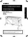 1
1
-
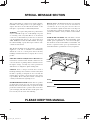 2
2
-
 3
3
-
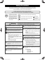 4
4
-
 5
5
-
 6
6
-
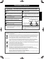 7
7
-
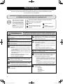 8
8
-
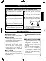 9
9
-
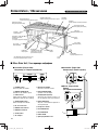 10
10
-
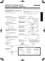 11
11
-
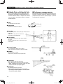 12
12
-
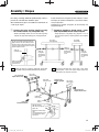 13
13
-
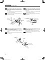 14
14
-
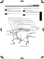 15
15
-
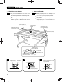 16
16
-
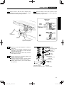 17
17
-
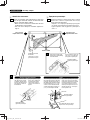 18
18
-
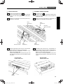 19
19
-
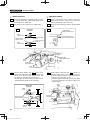 20
20
-
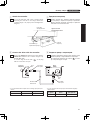 21
21
-
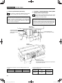 22
22
-
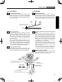 23
23
-
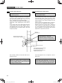 24
24
-
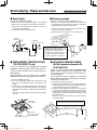 25
25
-
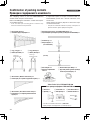 26
26
-
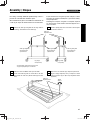 27
27
-
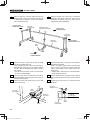 28
28
-
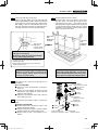 29
29
-
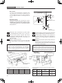 30
30
-
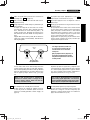 31
31
-
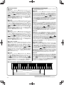 32
32
-
 33
33


Yamaha YV-4110 El manual del propietario
- Tipo
- El manual del propietario
en otros idiomas
- français: Yamaha YV-4110 Le manuel du propriétaire
- italiano: Yamaha YV-4110 Manuale del proprietario
- English: Yamaha YV-4110 Owner's manual
- Deutsch: Yamaha YV-4110 Bedienungsanleitung
- русский: Yamaha YV-4110 Инструкция по применению
- Nederlands: Yamaha YV-4110 de handleiding
- português: Yamaha YV-4110 Manual do proprietário
- dansk: Yamaha YV-4110 Brugervejledning
- polski: Yamaha YV-4110 Instrukcja obsługi
- čeština: Yamaha YV-4110 Návod k obsluze
- română: Yamaha YV-4110 Manualul proprietarului
Artículos relacionados
-
Yamaha YV3030MS VIBRAPHONE Manual de usuario
-
-
-
-
-
-
-
-
-