
P/NO : MFL67646802
Rev.01_072516
www.lg.com
http://www.lghvac.com
Please read this manual carefully before operating
your set and retain it for future reference.
TYPE : Room Air Conditioner
ENGLISH ESPAÑOL FRANÇAIS
OWNER'S MANUAL
AIR
CONDITIONER

2 Room Air Conditioner
Packaged Terminal Air Conditioner/Heat Pump Owner's Manual
TABLE OF CONTENTS
FOR YOUR RECORDS
Write the model and serial numbers here:
Model #
Serial #
Dealer's Name
Date Purchased
Staple your receipt to this page in the event you need it
to prove date of purchase or for warranty issues.
READ THIS MANUAL
Inside you will find many helpful hints on how to use and
maintain your air conditioner properly. Just a little
preventive care on your part can save you a great deal of
time and money over the life of your air conditioner.
You'll find many answers to common problems in the chart
of troubleshooting tips. If you review our chart of
Troubleshooting Tips first, you may not need to call for
service at all.
PRECAUTION
• Contact an authorized service technician for repair or
maintenance of this unit.
• Contact the installer for installation of this unit.
• The air conditioner is not intended for use by young
children or invalids without supervision.
• Young children should be supervised to ensure that
they do not play with the air conditioner.
• When the power cord is to be replaced, replacement
work shall be performed by authorized personnel
only using only genuine replacement parts.
• Installation work must be performed in accordance
with the National Electric Code by qualified and
authorized personnel only.
You can find them on quality label and front of base pan of
each unit.
Safety Precautions..........................3
Before Operation.............................7
Introduction ....................................8
Electrical Safety ..............................9
Installation .....................................11
Control Locations .........................13
Maintenance and Service ............19

Ownerʼs Manual 3
ENGLISH
Safety Precautions
Safety Precautions
Incorrect operation due to ignoring instruction will cause harm or damage. The seriousness
is classified by the following indications.
Meanings of symbols used in this manual are as shown below.
WARNING
CAUTION
This symbol indicates the possibility of death or serious injury.
This symbol indicates the possibility of injury or damage to properties only.
Following instructions must be followed to prevent injury to the user and property damages.
WARNING
n Installation
Don't do this!
Be sure to follow the instruction.
Donʼt use a power cord, a
plug, or a loose socket
which is damaged.
• It may cause a fire or electrical
shock.
Always plug into a grounded
outlet.
• It may cause a fire or electrical
shock.
Do not modify or extend the
power cord length.
• It will cause electric shock or fire
due to heat generation.
Do not disassemble or
modify products.
• It may cause failure and
electric shock.
Be caution when unpacking
and installing.
• Sharp edges may cause
injury.
Do not use the power cord near
flammable gas or combustibles
such as gasoline, benzene,
thinner, etc.
• It may cause explosion or fire.
Gasolin

4 Room Air Conditioner
Safety Precautions
n Operation
Do not place the power cord
near a heater.
• It may cause fire and electric
shock.
Do not allow water to run
into electric parts.
• It will cause failure of machine or
electric shock.
Use a soft cloth to clean. Do
not use wax, thinner, or a
strong detergent.
• The appearance of the air
conditioner may deteriorate,
change color, or develop
surface flaws.
Wax
Thinner
Ventilate the room well when
using this appliance
together with a stove, etc.
• Oxygen depletion could occur.
Turn off the power and
breaker when cleaning the
unit.
• Moving parts could cause injury.
Turn off the main power
switch when not using it for
a long time.
• Prevent accidental startup and
the possibility of injury.
Unplug the unit if strange
sounds, odors, or smoke
come from it.
• It could represent a fire hazed.
Do not open the suction
inlet grill of the product
during operation.
• Otherwise, it may electrical
shock and failure.
If water enters the product, turn
off the the power switch of the
main body of appliance. Contact
service center after taking the
power plug out from the socket.
Do not place objects on the
power cord. Protect the
cord from being pinched or
damaged.
• There is danger of fire or electric
shock.
Use a dedicated circuit for
this appliance.
• An overloaded circuit is a fire
hazard.
Take the power plug out if
necessary, holding the end
of the plug and do not touch
it with wet hands.
• It may cause a fire or electrical
shock.

Ownerʼs Manual 5
ENGLISH
Safety Precautions
CAUTION
n Installation
Do not operate or stop the
unit by inserting or pulling
out the power plug.
• It will cause electric shock or fire
due to heat generation.
Do not damage or use an
unspecified power cord.
• It will cause electric shock or fire.
Do not operate with wet
hands or in damp
environment.
• It will cause electric shock.
Hold the plug by the end
when taking it out.
• It may cause electric shock and
damage.
When gas leaks, open the
window for ventilation
before operating the unit.
• Otherwise, it may cause an
explosion and a fire.
Never touch the metal parts
of the unit when removing
the filter.
• They are sharp and may cause
injury.
Install the product so that the noise or
exhaust from the outdoor unit may not
cause any damage to the neighbors.
• Be considerate of your neighbor.
Be sure the product is level front-to-back
and side-to-side when installing.
• It may cause vibration or water leakage.
For inner cleaning, contact an Authorized Service Center or a dealer.
Do not use harsh detergent that causes corrosion or damage on the unit.
• Harsh detergent may also cause failure of product, fire, or electronic shock.

6 Room Air Conditioner
Safety Precautions
n Operation
Be cautious not to touch the
sharp edges when installing.
• A severe cut or other injury could result.
Avoid excessive cooling and
perform ventilation sometimes.
• Use the ventilation function to circulate
air without cooling or heating
Do not insert hands or other
objects through the air inlet or
outlet during operation.
• Electrical and moving parts could cause
shock or injury.
If the liquid from the batteries gets onto your skin or
clothes, wash it well with clean water. Do not use the
remote if the batteries have leaked.
• The chemicals in batteries could cause burns or other health
hazards.
If you eat the liquid from the batteries, brush your teeth
and see doctor. Do not use the remote if the batteries
have leaked.
• The chemicals in batteries could cause burns or other health
hazards.
Do not put a pet or house plant
where it will be exposed to direct
air flow.
• It is not good to sit in the draft.
Do not block the inlet or outlet of
air flow.
• It may cause product failure.
Use a soft cloth to clean. Do not
use wax, thinner, or a strong
detergent.
• The appearance of the air conditioner
may deteriorate, change color, or
develop surface flaws.
Do not step on the indoor/outdoor
unit and do not put anything on it.
• It may cause an injury through dropping
of the unit or falling down.
Always insert the filter securely.
Clean it every two weeks.
• Operation without filters will cause
failure.
Do not drink water drained from
the air conditioner.
• It contains every contaminant
condensed from the air and could cause
health issues.

Ownerʼs Manual 7
ENGLISH
Before Operation
Before Operation
1. Contact an installation specialist for installation.
This is NOT a do-it-yourself project.
2. Plug in the power plug properly.
3. Use a dedicated circuit.
4. Do not use an extension cord. Consult a professional installer or electrician.
5. Do not start/stop operation by plugging/unplugging the power cord.
6. If the cord/plug is damaged, replace it with only an authorized replacement
part.
1. Being exposed to direct airflow for an extended period of time could be
hazardous to your health. Do not expose occupants, pets, or plants to direct
airflow for extended periods of time. In other words, don't sit in the draft.
2. Due to the possibility of oxygen deficiency, ventilate the room when used
together with stoves or other heating devices.
3. Do not use this air conditioner for non-specified special purposes (e.g.
preserving precision devices, food, pets, plants, and art objects). Such usage
could damage the items.
1. Do not touch the metal parts of the unit when removing the filter. Injuries can
occur when handling sharp metal edges.
2. Do not use water to clean inside the air conditioner. Exposure to water can
destroy the insulation, leading to possible electric shock.
3. When cleaning the unit, first make sure that the power and breaker are turned
off. The fan rotates at a very high speed during operation. There is a
possibility of injury if the unitʼs power is accidentally triggered on while
cleaning inner parts of the unit.
For repair and maintenance, contact your authorized service dealer.
Preparing for Operation
Usage
Cleaning and Maintenance
Service

8 Room Air Conditioner
Introduction
This symbol alerts you to the risk of electric shock.
This symbol alerts you to hazards that could cause harm to
the air conditioner.
This symbol indicates special notes.
NOTICE
This air conditioner should be installed in accordance with the National Electric Code.
Expanded Metal Grille Should be applied for better performance in PTAC and PTHP Units.
For Installation purpose and better appearance Aluminium or Architectural grille can be applied in
PTAC and PTHP Units.
INDOOR
REAR GRILLE
(Aluminum Rear Grille)
Architecture Rear Grille
EXPANDED METAL GRILLE
SLEEVE ASSEMBLY
THE SLEEVE AND THE REAR GRILLE
(Available as an option)
VERTICAL AIR DEFLECTOR
(Horizontal Louver)
AIR FILTER
FRONT GRILLE
(Air Intake)
Introduction
Symbols Used in this Manual
Features

Ownerʼs Manual 9
ENGLISH
Electrical Safety
Electrical Safety
Electrical Data
208/230V~ 265V~
Power cord may include a current interrupter device.
A test and reset button is provided on the plug case.
The device should be tested on a periodic basis by first
pressing the TEST button and then the RESET button.
If the TEST button does not trip or if the RESET button
will not stay engaged, discontinue use of the air
conditioner and contact a qualified service technician.
*In the case of 265V power cord doesn’t have current
interrupter device.
Use Wall Receptacle Power Supply
Standard 208/230V, 3-wire
grounding receptacle rated 15A
Standard 208/230V, 3-wire
grounding receptacle rated 20A
Standard 208/230V, 3-wire
grounding receptacle rated 30A
Standard 265V grounding
receptacle rated 20A
Standard 265V grounding
receptacle rated 30A
Use 15 AMP. time
delay fuse or 15 AMP.
Circuit breaker.
Use 20 AMP. time
delay fuse or 20 AMP.
Circuit breaker.
(2500W Heater ơ15AMP.
Circuit Breaker)
Use 30 AMP. time
delay fuse or 30 AMP.
Circuit breaker.
Use 20 AMP. time
delay fuse or 20 AMP.
Circuit breaker.
Use 30 AMP. time
delay fuse or 30 AMP.
Circuit breaker.
Never push the test button during
operation
Otherwise this plug can damaged.
This device contains chemicals, including
lead, known to the State of California to
cause cancer, birth defects, or other
reproductive harm.
Wash hands after handling.
Do not remove, modify, or immerse this plug.
If this device trips, the cause should be
corrected before further use.
The conductors inside this cord are
surrounded by shields, which monitor
leakage current.
These shields are not grounded.
Periodically examine the cord for any
damage. Do not use this product in the
event the shields become exposed.
Avoid shock hazard! This unit cannot
be serviced. Opening the tamper-
resistant, sealed portion of the unit
voids all warranties and performance
claims. This unit is not intended to be
an ON/OFF switch.
The shape may be different according to its model.
NOTICE
DO NOT USE AN EXTENSION CORD on 230,
208, and 208/230, 265 Volt units.
All wiring should be made in accordance with local
electrical codes and regulations.
Aluminum house wiring may pose special
problems. Consult a qualified electrician.
NOTICE

10 Room Air Conditioner
Electrical Safety
IMPORTANT
(PLEASE READ CAREFULLY)
FOR THE USER'S PERSONAL SAFETY, THIS
APPLIANCE MUST BE PROPERLY GROUNDED
The power cord of this appliance is equipped with a
three-prong (grounding) plug. Use this with a standard
three-slot (grounding) wall power outlet to minimize
the hazard of electric shock. The customer should
have the wall receptacle and circuit checked by a
qualified electrician to make sure the receptacle is
properly grounded.
DO NOT CUT OR REMOVE THE THIRD (GROUND)
PRONG FROM THE POWER PLUG.
A. SITUATIONS WHEN THE APPLIANCE WILL BE
DISCONNECTED OCCASIONALLY
Because of potential safety hazards, we strongly
discourage the use of an adapter plug. However, if
you wish to use an adapter, a TEMPORARY
CONNECTION may be made. Use UL-listed adapter,
available from most local hardware stores.
The large slot in the adapter must be aligned with the
large slot in the receptacle to assure a proper polarity
connection.
Attaching the adapter ground terminal to the wall
receptacle cover screw does not ground the
appliance unless the cover screw is metal, and not
insulated, and the wall receptacle is grounded
through the house wiring. The customer should
have the circuit checked by a qualified electrician to
make sure the receptacle is properly grounded.
Disconnect the power cord from the adapter, using
one hand on each. Otherwise, the adapter ground
terminal might break. DO NOT USE the appliance with
a broken adapter plug.
B. SITUATIONS WHEN THE APPLIANCE WILL BE
DISCONNECTED OFTEN
Do not use an adapter plug in these situations.
Unplugging the power cord frequently can lead to an
eventual breakage of the ground terminal. The wall
power outlet should be replaced by a three-slot
(grounding) outlet instead.
USE OF EXTENSION CORDS
Because of potential safety hazards, we strongly
discourage the use of an extension cord. However, if
you wish to use an extension cord, use a CSA
certified/UL-listed 3-wire (grounding) extension cord.
Electrical Safety

Ownerʼs Manual 11
ENGLISH
Installation
How to Install the Unit
Installation
406 mm
(16")
1,066 mm
(42")
349 mm
(13
3
/
4
")
536 mm
(21")
Dimension of air conditioner
Dimension of sleeve assembly (optional)
Over 20"
HEAT
RADIATION
WALL
WALL
INSULATION
SLEEVE
INTAKE
AIR
COOLED
AIR
1/4" Bubble
of the level
Over 20"
Front
Insulation Strip
Rear
Sleeve
280 mm
(11")
406 mm
(16")
1066 mm
(42")
349 mm
(13
3
/
4
")
Insulation
Joint Gap
• Need 2 people to lift up air conditioner, it is HEAVY.
For existing sleeve, you should measure the wall sleeve
dimensions.
You can install the new air conditioner according to these
installation instructions to achieve the best performence. All
wall sleeves used to mount the new air conditioner must be in
good structural condition and have the rear grille that securely
attached to the sleeve or the flange of the sleeve to secure the
new air conditioner.
• To avoid vibration and noise, make sure the unit is installed
securely and firmly.
When installing the sleeve & Front grille, make certain there is
nothing within 21” back & front of sleeve & front grille, that
would interfere with heat radiation and exhaust air flow.
• Before installation, Check the insulation on the inner side of
the sleeve. If there is no insulation, place the insulation.
• Check the bottom corner's joint gap of the sleeve, If there is,
fill the gap with putty.
To maintain the best performance
of LG PTAC
1. An insulation strip must be attached. The
insulation strip is provided with the box.
2. After assembly of sleeve & front grille, the
gap should be over 20” from both sleeve &
grille. For assembly PTAC Model refer the
diagram.
1) Take out the insulation strip from the upper packing.
2) Attach the insulation strip onto the rear upper side of the
wall sleeve.
NOTICE

12 Room Air Conditioner
Installation
• UNIT INSTALLATION
1. Remove the shipping screw from the ventilation door.
2. Remove the front gille by pulling it out at the bottom
to release it, then lift it up along the unit top front.
6. Slide the unit into the wall sleeve and secure with
4 screws through the unit flange holes.
3. Remove cover by removing 3 screws from front.
7. Reinstall the front grille by hooking the top over the
unit top, then pushing it in at the bottom.
4. Connect accessory power supply cord, and fix power
cord to basepan with screws.
5. Replace cover with screws. Tighten securely.
ELECTRIC HEATER RATING
(CONFIGURATION BASED ON POWER CORD)
POWER CORD
AYUH2115 2 400/2 300 W
230/208
230/208
3 300/3 200 W
230/208
15 A
20 A
30 A4 700/4 600 W
AYUH2120
AYUH2130
VOLTAGE
WATTS
HEATER
CURRENT
HEATER MAX.
FUSE SIZE
MIN.CIRCUIT
AMPACITY
14.5 A
19.8 A
28.3 A
10.5/11.2 A
14.5/15.5 A
20.6/22.3 A

Ownerʼs Manual 13
ENGLISH
Control Locations
Control Locations
Manual Controls
• VENTILATION
The ventilation lever is located to the lower left side
of the unit.
The ventilation lever must be in the CLOSE position in
order to maintain the best cooling & heating conditions.
When fresh air is necessary in the room, set the
ventilation lever to the OPEN position.
The Ventilation door is opened and outdoor air is
drawn into the room.
This will reduce the cooling or heating efficiency.
When the air conditioner has been running and is
turned off or set to the fan position, wait at least 3
minutes before resetting to the cooling & heating
operations.
Note:
A slight heat odor may come from the unit
when first switching to HEAT after the
cooling season is over.
This odor, caused by fine dust particles on
the heater, will disappear quickly.
This is harmless.
VENT
OPEN
VENT
CLOSE
Ventilation door
• Failure to follow this caution may result in equipment
damage or improper operation.
• Blocking indoor(curtain or bedclothes etc.) or outdoor
discharge air could cause premature failure of unit.
INDOOR
IN
D
OO
R
•
If there has a gap between rear side of product &
outside wall, the air splitter need to be used on
unit.
Sleeve
Wall
Outside Wall
Air Splitter
Rear side of product

14 Room Air Conditioner
Control Locations
Electronic Controls
POWER
MODE
-
Push this button to cycle through the modes from
COOL
FAN HEAT COOL.
- COOL
• Fan runs continually for normal cooling operation.
- ENERGY SAVER
• The fan stops when the compressor stops cooling & heating
operations. Approximately every 3 minutes the fan will turn on and
the unit will check the room air temperature to determine if cooling
& heating is needed.
• For Energy saver operation Dip switch #2 is ON position. Refer
Dipswitch setting at P.No 16
- FAN
• Fan operation without heating or cooling.
- HEAT
• Fan runs continually for normal heating operation.
TIMER
- SHUT-OFF TIME
• You will usually use shut-off time while you sleep.
• If unit is running, use Timer to set number of hours until shut-off.
• For your sleeping comfort, once Time is set, the setting temperature will raise 2°F after 30 minutes, and once again
after another 30 minutes.
• Push Timer to cycle through the settings from 1 Hour
2 Hours ... 12 Hours maximum.
FAN SPEED
• Every time you push this button, it cycles through the settings as follows:
{High(F2)
Low(F1) High(F2)}
• To turn ON the air conditioner, push this button.
To turn OFF the air conditioner, push this button
again.
• This button takes priority over any other button.
TEMPERATURE SETTING
• Use this button to automatically control the
temperature of the room.
The temperature can be set within a range of
54°F (12°C) to 86°F (30°C) by increments of
1°F (0.5°C).
• The setting temperature in the display.
°F

Control Locations
Owner’s Manual 15
ENGLISH
Self-Diagnosis
FUNCTION:
If the unit has a malfunction, a green OPERATION LED located on the Display PCB used by the unit to
indicate the fault codes.
USE:
If the customer has to register a complaint to the service center, he can be very clear about registering
the complaint that what is happening & by referring the user's manual the customer can clearly define
the problem.
So that the engineer should go fully prepared with the prescribed tools to be used regarding that
problem. It also keeps the customer aware about the unit.
Here are some of the problems defined below for which the LED indicates by flashing.
The fault codes are the mentioned which is as follows:
• Electrical Controls
NOTICE
ON Normal
OFF No power / failed board
Fault Codes
CH 01
Indoor Air Thermistor Error
CH 02
Indoor Coil Thermistor Error
CH 07
Themostat Wiring Error
CH 09
EEPROM Check Sum Error
CH 10
Indoor Fan Error
CH 34
High Pressure Switch Error
CH 44
Outdoor Air Thermistor Error (PTHP Only)
CH 45
Outdoor Coil Thermistor Error (PTHP Only)
CH 67
Outdoor Fan Error
Function Description Display code
Over heating Protection
This feature prevents melting of unit by electrical heater
located inside of the unit at the remote mode (when the
unit is connected with wall thermostat).
°F
Freeze Protection
This feature prevents freezing of room at low
temperature.
°F
Remote Mode When use the remote mode operation
°F

16 Room Air Conditioner
Control Locations
Additional Controls
• REMOVING THE FRONT GRILLE
Additional controls are available after
removing the front grille and option
cover of control box.
To remove the front grille, pull out the
bottom of front grille and then lift up.
To reinstall the front grille, place the tabs
over the top of the unit and push the
bottom of front grille until the clips snap
into place.
• ADDITIONAL CONTROLS
The additional controls are located behind the option cover of control box. The standard settings will be in
the OFF position. The authorized service engineer has to check switches and ensure the switches are in
the desired position.
ON
ONREMOTE
OFF
ON ON ON
Remote/Local
Energy Saver
Temperature Limit 1
Temperature Limit 2
Temperature Limit 3
PTAC/PTHP
UNIT TYPE
LOCAL
1
OFF
2
OFF
3
OFF
4
OFF
5
LOCAL
1
OFF
2
OFF
3
OFF
4
OFF
5
LOCAL
1
OFF
2
OFF
3
OFF
4
OFF
5
LOCAL
1
OFF
2
OFF
3
OFF
4
OFF
5
OFF
6
OFF
7
LOCAL
1
OFF
2
OFF
3
OFF
4
OFF
5
LOCAL
1
OFF
2
OFF
3
OFF
4
OFF
5
OFF OFF OFF 54 F (12.2 C) 86 F (30.0 C)
86 F (30.0 C)
86 F (30.0 C)
86 F (30.0 C)
86 F (30.0 C)
86 F (30.0 C)
86 F (30.0 C)
86 F (30.0 C)
54 F (12.2 C)
54 F (12.2 C)
54 F (12.2 C)
54 F (12.2 C)
54 F (12.2 C)
54 F (12.2 C)
54 F (12.2 C)
54 F (12.2 C)
86 F (30.0 C)
ON OFF OFF 56 F (13.3 C) 84 F (28.9 C)
OFF ON OFF 58 F (14.4 C) 82 F (27.8 C)
ON ON OFF 60 F (15.5 C) 80 F (26.7 C)
OFF )C 5.52( F 87)C 6.61( F 26NOFFO
ON OFF ON 64 F (17.7 C) 76 F (24.4 C)
OFF ON ON 66 F (18.9 C) 74 F (23.3 C)
ON ON ON 68 F (20.0 C) 72 F (22.2 C)
Temperature Temperature Temperature
Limit #1 Limit #2 Limit #3
Lowest Temp. Highest Temp. Lowest Temp. Highest Temp.
Cooling Operation noitarepO gnitaeH5#4#3#
Dip switch setting is done at factory according to product specification.
• TEMPERATURE LIMITING
Temperature Limiting can save money by limiting the lowest temperature for cooling and the highest temperature for heating.
The temperature limiting is controlled by switches #3 - #5.
This temperature limiting is not available with the Remote Wall Thermostat.
#6 #7 Unit Type
OFF OFF Cooling+Electric Heater+Heat Pump
OFF ON Cooling+Electric Heater
ON OFF Heat Pump Only
ON ON Cooling Only

• REMOTE/LOCAL CONTROL
When remote/local switch #1 is on, it allow the unit to operate by the Remote Wall Thermostat.
The unit control by buttons are not available.
• ENERGY SAVER
The energy saver switch #2 is on. This switch is set at cycle fan to provide continuous fan operation in cool
or heat modes. When the switch is off the continuous fan allows continuous circulation of room air and
make the more balanced temperature of the room. When the switch is on, the fan is on or off with the
compressor or with the heater.
• FRONT DESK CONTROL
When the pair wire is connected to the connector FD2 and FD1, the unit can be turned ON or OFF with a
switch located at the Front Desk Control panel. When the front desk switch is ON, the fan operates
according to the setting without working compressor and heater. When the front desk switch is OFF, the unit
can operate according to the setting of controls.
• REMOTE WALL THERMOSTAT
When the wires are connected, the unit will be controlled
by a remote wall thermostat.
The thermostat connections supply the 24 Volt AC. When
you install the digital/electronic thermostat, you
must set it
to 24 Volt AC.
GL GH O W Y R C
Low Fan
High Fan
Reversing Valve
Heater
Compressor
24 Volt-L
24 Volt-N
Wire # AWG Maximum Length
#22 600 ft (180 m)
#20 900 ft (270 m)
#18 1500 ft (450 m)
#16 2000 ft (610 m)
FD2 FD1 DR2 DR1 MS2 MS1
Front Desk Control
Front Desk Control
(Molex Housing Spec 396-06V)
(Molex Housing Spec 396-07V)
Room Air Conditioner 17
Control Locations
ENGLISH
NOTICE
For wiring connection of Wall Thermostat, check the Installation instruction or Installation manual’s
provided by Thermostat Company.

18 Room Air Conditioner
Control Locations
1. Remove the front grille.
2. To remove the front grille, pull out the bottom
of the front grille and then lift up.
Re-install the component by referring to the
removal procedure.
3. To reinstall the front grille, place the tabs over
the top of the unit and push the bottom of front
grille until the clips snap into place.
• This Room Air Conditioner (PTAC) discharges
air from the top of the unit through reversible, 2-
position discharge grille louvers. The unit is
shipped from the factory with the discharge grille
louvers at an angle of 40” off vertical. In an
alternate position the louvers will be at an angle
of 15” off vertical.
To adjust the air direction, remove the front
grille. Remove the 4 screws that fasten the
discharge grille to the front grille.
Rotate the discharge grille 180°, then assembly the
discharge grille to the front grille with 4 screws.
Disassembly Instructions
- Before the following disassembly, POWER SWITCH is set to OFF and disconnected the power
cord.
Screws
INDOOR
INDOOR
40˚
15˚
INDOOR

Maintenance and Service
Ownerʼs Manual 19
Maintenance and Service
Air Filter Cleaning
Vent Filter
TURN OFF THE AIR CONDITIONER AND REMOVE THE PLUG FROM THE POWER OUTLET.
The air filter should be checked at least twice a month to see if cleaning is necessary.
Trapped particles in the filter will build up and block the airflow. This reduces the cooling
capacity and also causes an accumulation of frost on the cooling coils.
If the filter becomes turn or damaged you should replace
immediately. Replacement filters are available from your
salesperson, dealer, and the authorized customer service
centers.
1. Remove the air filter from the front grille assembly by
pulling the air filter up slightly.
2. Wash the filter using lukewarm water below 104° F(40°C).
3. Gently shake the excess water from the filter completely.
Reinstall the filter.
Before cleaning the vent filter, disconnect power to the
unit by unplugging the power cord at the wall outlet or
subbase, or disconnect power at the fuse box or circuit
breaker. If unit is operated with vent door closed, the
vent filter does not need to be cleaned.
1. Remove the front grille as described in front grille
Removal.
2. Remove the 4 screws securing the chassis to the
wall sleeve with a Phillips-Head screwdriver.
3. Slide the chassis out of the wall sleeve far enough so
that the vent filter is accessible as shown in Figure A.
4. Remove the vent filter by unscrewing the two screws
at the top of the filter and gently pulling the filter away
from the partition panel. Refer to Figure B.
5. Clean and reinstall the filter by reattaching the hook
to the bottom of the vent door and replacing the two
screws, slide the chassis back into the wall sleeve,
secure it in place with 4 screws and reinstall the
front cabinet.
Figure A – Vent (Left side of unit)
Figure B – Vent Filter Removal
INDOOR
ENGLISH

20 Room Air Conditioner
Maintenance and Service
Chassis
Front Grille
Compressor / Fan Motor
The chassis must be cleaned every four months or more often as the atmospheric conditions
require. Use water and detergent to clean the basepan, center partition and coils. The use of harsh
cleaning materials may cause a deterioration of the coil fins or endplates. Do not use a high
pressure cleaner as it could cause severe damage to the PTAC fins and coils. A hose is okay to use
to clean the coils, but make sure to cover the control with a blanket or plastic bag to keep it dry.
The base pan may overflow due to high humidity.
To drain the excess water, remove the drain cap
from the back of the unit.
The compressor and fan motor are hermetically sealed, permanently lubricated, and require no
additional oiling.
The Front Grille and discharge air grille can be cleaned with a mild soap or detergent. Under no
circumstances should hydrocarbon based cleaners (e.g. acetone, benzene, naphtha, gasoline, etc.)
be used to clean the front or air grilles.
Use care when cleaning the control area. Do not use an excessively wet cleaning cloth.
Drainage
Drain Cap

Maintenance and Service
Ownerʼs Manual 21
Problem Possible Causes What To Do
The air conditioner is
unplugged.
Make sure the air conditioner plug is pushed
completely into the outlet.
The fuse is blown/circuit
breaker is tripped.
Check the house fuse/circuit breaker box and
replace the fuse or reset the breaker.
Power failure. If power failure occurs, turn the mode control
to Off. When power is restored, wait 3
minutes to restart the air conditioner to
prevent tripping of the compressor overload.
The current interrupter
device is tripped.
Press the RESET button located on the power
cord plug. If the RESET button will not stay
engaged, discontinue use of the air conditioner
and contact a qualified service technician.
Airflow is restricted. Make sure there are no curtains, blinds, or
furniture blocking the front of the air
conditioner.
The temp control may not
be set correctly.
In COOL mode, press the " - " pad.
In HEAT mode, press the " + " pad.
The air filter is dirty. Clean the filter at least every 2 weeks.
See the care and Maintenance section.
The room may have been hot. When the air conditioner is first turned on,you
need to allow time for the room to cool down.
The room may have been cold. When the air conditioner is first turned on,you
need to allow time for the room to heat up.
Col
d air is escaping. Check for open furnace floor registers and
cold air returns.
Hot air is escaping.
Make sure that all vents are closed to air returns.
Cooling coil have iced up. See Air Conditioner Freezing Up below.
Air conditioner
freezing up
The cooling coils are iced
over.
Ice may block the air flow and obstruct the air
conditioner from properly cooling the room.
Set the mode control at High Fan or High
Air conditioner
does not start
Air conditioner
does not
cool/Heat
as it should
Cool.
Troubleshooting
ENGLISH
Common Problems and Solutions
Normal Operation
Troubleshooting Tips save time and money!
Review the chart below first and you may not need to call for service.
• You may hear a pinging noise caused by water being picked up and thrown by the slinger fan against the
condenser on rainy days or when the humidity is high. This design feature helps remove moisture and
improve efficiency.
• You may hear the thermostat click when the compressor cycles on and off.
• Water will collect in the base pan during high humidity or on rainy days. The water may overflow and drip
from the outdoor side of the unit.
• The fan may run even when the compressor does not.

22 Room Air Conditioner
Maintenance and Service
Problem Possible Causes What To Do
Hot, humid weather. This is normal.
Water drips
indoors
The air conditioner is not
tilted to the outside.
For proper water disposal, make sure the air
conditioner slants slightly from the case front
to the rear.
Water collects
in base pan
Moisture removed from air
and drains into base pan.
This is normal for a short period in areas with
little humidity; normal for a longer period in
very humid areas.
Dirty air fi
lter - air restricted. Clean air filter.
Outside temperature
extremely hot.
Set FAN speed to a faster setting to bring air
through cooling coils more frequently.
Air movement sound.
Poor installation. Refer to installation instructions or check with
installer.
Set temperature too low Increase set temperature
Set temperature too high Decrease set temperature
Room too
cold/heat.
Air conditioner
turns on and
off rapidly.
Noise when
unit is
cooling/Heating
This is normal. If too loud, set to lower FAN setting.
Water drips
outside

Maintenance and Service
Ownerʼs Manual 23
ENGLISH

24 Aparato de aire acondicionado
PARA SUS ARCHIVOS
Escriba aquí el modelo y número de serie:
Modelo n°:
Serie n°:
Puede encontrarlos en la etiqueta de calidad y el panel frontal
de la base de cada unidad.
Nombre del distribuidor:
Fecha de compra:
Adjunte su recibo a esta página con la grapadora para el
momento que lo necesite para probar la fecha de su
adquisición o para la validación de la garantía.
LEA ESTE MANUAL
En su interior encontrará muchos consejos útiles sobre la
utilización y mantenimiento de su acondicionador de aire.
Unos pocos cuidados por su parte le pueden ahorrar
mucho tiempo y dinero durante la vida de su
acondicionador de aire.
En la tabla de consejos para la solución rápida de
problemas encontrará muchas respuestas a los problemas
más habituales. Si revisa primero nuestra Tabla de
Consejos para la solución rápida de problemas, tal vez no
necesite llamar nunca al servicio técnico.
PRECAUCIÓN
• Póngase en contacto con un técnico del servicio
autorizado para realizar la reparación y
mantenimiento de esta unidad.
• Póngase en contacto con un instalador para realizar
la instalación de esta unidad.
• Cuando se va a cambiar el cable eléctrico, el trabajo
de reemplazamiento debe ser realizado únicamente
por personal autorizado, utilizando las piezas de
cambio genuinas únicamente.
• El trabajo de reemplazamiento debe ser realizado de
acuerdo con el Código Eléctrico Nacional únicamente
por personal autorizado.
Precauciones de Seguridad .........25
Antes de poner el equipo en
funcionamiento..............................29
Introducción...................................30
Seguraida Electrica.......................31
Instalacion......................................33
Ubicación de los controles...........35
Mantenimiento y asistencia
técnica............................................41
Manual del usuario del acondicionador de aire tipo Ventana
TABLA DE CONTENIDOS

Manual del propietario 25
ESPAÑOL
Precauciones de Seguridad
Precauciones de Seguridad
Se deben seguir las siguientes instrucciones, para evitar lesiones al usuario y daños a la propiedad.
Una operación incorrecta por ignorar las instrucciones provocará lesiones o daños. La seriedad se clasifica
por las siguientes indicaciones.
Meanings of symbols used in this manual are as shown below.
ADVERTENCIA
PRECAUCION
Este símbolo indica la posibilidad de muerte o de seria lesión.
Este símbolo indica sólo la posibilidad de lesiones o daños a la propiedad
ADVERTENCIA
n Instalación
No hacer.
Siga estas instrucciones.
No utilice un cable de
alimentación, enchufe o una
toma suelta que esté dañada.
• De lo contrario, podría provocar
un incendio o descarga
eléctrica.
Enchufe siempre a un
tomacorriente que tenga
toma a tierra.
• De lo contrario, podría provocar
un incendio o descarga
eléctrica.
No modifique ni alargue el
cable de alimentación.
• De lo contrario, puede provocar
una descarga eléctrica o
incendio debido a la generación
de calor.
No desmonte ni modifique
los productos.
• Puede ocasionar fallos y una
descarga eléctrica.
Tenga cuidado al
desembalar e instalar el
aparato.
• Los bordes afilados pueden
provocar lesiones.
No use el cable de alimentación
cerca gas inflamable o
materiales combustibles tales
como la gasolina, benceno,
disolvente, etc.
• Podría ocurrir una explosión o
incendio.
Gasolin

26 Aparato de aire acondicionado
Precauciones de Seguridad
n Operación
No ponga el cable de
alimentación cerca de un
calentador.
• Puede ocasionar un incendio y
una descarga eléctrica.
No permita que entre agua
en las piezas eléctricas.
• Puede provocar fallos en el
producto o descargas
eléctricas.
Utilice un paño suave para
limpiar. No utilice cera,
disolventes o detergentes fuertes.
•
La apariencia del aparato de aire
acondicionado puede deteriorar,
cambiar el color o desarrollar flujos en
las superficies.
Wax
Thinner
Ventile bien la sala al usar
este aparato con una estufa,
etc.
• Puede ocurrir un falta de
oxígeno.
Apague el aparato y el
interruptor diferencial
primero antes de limpiar la
unidad.
•
Debido a que el ventilador gira a
alta velocidad durante el
funcionamiento, podría ocasionar
lesiones.
Apague el interruptor de
alimentación principal cuando
no vaya a utilizar el aparato
durante mucho tiempo.
• Evitará el arranque accidental y
la posibilidad de lesiones.
Desenchufe la unidad si oye
un sonido extraño, olores, o
si observa salir humo.
• De lo contrario, puede ocurrir
un incendio y un accidente por
descarga eléctrica.
No abra la parrilla de
entrada al aparato mientras
está en funcionamiento.
• De lo contrario, pueden ocurrir
descargas eléctricas y fallos.
Si entra agua en el producto,
apague el interruptor de la carcasa
principal del aparato. Póngase en
contacto con el centro de servicio
después de haber sacado el
enchufe del tomacorriente.
No use el cable de alimentación
cerca gas inflamable o materiales
combustibles tales como la
gasolina, benceno, disolvente, etc.
• Puede ocasionar una explosión
o descarga eléctrica.
No comparta el
tomacorriente con otros
electrodomésticos.
•
De lo contrario, puede provocar una
descarga eléctrica o incendio debido
a la generación de calor.
Saque el enchufe en caso de
necesidad, sosteniendo la
cabeza del enchufe y no lo
toque con las manos mojadas.
•
De lo contrario, podría provocar un
incendio o descarga eléctrica.

Manual del propietario 27
ESPAÑOL
Precauciones de Seguridad
PRECAUCION
n Instalación
No opere ni detenga la
unidad insertando o
estirando de enchufe.
• De lo contrario, puede provocar
una descarga eléctrica o
incendio debido a la generación
de calor.
No dañe ni use un enchufe
de alimentación no
especificado.
• Provocará descargas eléctricas
o incendios.
No toque el producto con
las manos mojadas o en un
ambiente húmedo.
• Provocará descargas eléctricas.
Sostenga el enchufe por su
cabeza al sacarlo.
• Podría ocasionar una descarga
eléctrica y daños.
Cuando haya un escape de
gas, abra la ventana para
ventilar antes de poner en
marcha la unidad.
• De lo contrario, podría ocurrir
una explosión o incendio.
No toque las partes
metálicas del aparato al
sacar el filtro del aire.
• Son puntiagudas y pueden
provocar lesiones.
Instale el producto de modo que el ruido o
el aire caliente producido por la unidad
externa no moleste a los vecinos.
• De lo contrario puede dar lugar a disputas
vecinales.
Mantenga nivelado el producto al instalarlo.
• De lo contrario se podría causar vibraciones o
escapes de agua.
Para una limpieza interna, contacte con un centro de servicios autorizado o un revendedor.
No utilice detergentes abrasivos que puedan corroer o dañar la unidad.
• Los detergentes abrasivos pueden igualmente generar un fallo del producto, incendio, o descarga.

28 Aparato de aire acondicionado
Precauciones de Seguridad
n Operación
Tenga cuidado para no tocar los
bordes puntiagudos al instalar.
• Podría ocasionar lesiones.
Evite un enfriamiento excesivo y
ventile en ocasiones.
• De lo contrario, podría dañar su salud.
No introduzca la mano ni barras en
la entrada o salida del aire durante
el funcionamiento del aparato.
• De lo contrario, podrían ocurrir lesiones
personales.
Si entra líquido de las pilas en contacto con la piel o
ropa, lávela inmediatamente con agua. No utilice el
mando a distancia si las pilas tienen fugas.
• Los productos químicos de las pilas podrían causar
quemaduras u otros perjuicios a la salud.
Si el líquido de las pilas alcanzara su boca, cepille sus
dientes y consulte a un médico.No utilice el mando a
distancia si las pilas han experimentado fugas.
• Los productos químicos de las pilas podrían causar
quemaduras u otros perjuicios a la salud.
No ponga plantas ni animales en
la trayectoria que recorrerá el aire
caliente.
• Podría ocasionar lesiones.
No bloquee la entrada ni la salida
del flujo de aire.
• Puede causar una avería en el aparato.
Utilice un paño suave para
limpiar. No utilice cera,
disolventes o detergentes fuertes.
•
La apariencia del aparato de aire
acondicionado puede deteriorar, cambiar el
color o desarrollar flujos en las superficies.
No se suba a la unidad
interior/exterior ni coloque
objetos sobre la misma.
• Puede lesionarse al caerse del aparato o
al caerse los objetos que haya colocado.
Inserte siempre el filtro
correctamente.
Límpielo cada dos semanas.
• El funcionamiento sin filtros puede
provocar fallos.
No beba el agua que drena el
aparato de aire acondicionado.

Manual del propietario 29
ESPAÑOL
Antes de poner el equipo en funcionamiento
Antes de poner el equipo en funcionamiento
1. Póngase en contacto con un especialista para realizar la instalación.
2. Enchufe correctamente la toma de alimentación.
3. Utilice un circuito dedicado.
4. No utilice un cable alargador.
5. No inicie/cese el funcionamiento enchufando/desenchufando el cable
eléctrico.
6. Si el cable/enchufe está dañado, sustitúyalo solo por una pieza autorizada.
1. Estando expuesto a la circulación directa de aire durante un extenso período
de tiempo podría resultar peligroso para su salud. No exponga a las personas,
animales domésticos, o a las plantas a la circulación de aire durante largos
períodos de tiempo.
2. Debido a la probabilidad de falta de oxígeno, ventile el cuarto cuando esté
utilizado el aparato junto con estufas u otros aparatos de calefacción.
3. No utilice este aire acondicionado con propósitos especiales no especificados
(Ej.: conservación de dispositivos de precisión, comida, animales domésticos,
plantas y objetos de arte). Tal uso podría dañar los artículos.
1. No toque las piezas metálicas de la unidad al retirar el filtro. Manejar aristas
afiladas de metal puede causar lesiones.
2. No utilice el agua para limpiar el interior del aire acondicionado. La exposición
al agua puede destruir el aislamiento, conduciendo a posibles descargas
eléctricas.
3. Al limpiar la unidad, asegúrese antes de que la electricidad y el interruptor
están apagados. El ventilador rota a muy alta velocidad durante el
funcionamiento del equipo. Existe la posibilidad de lesiones si acciona
accidentalmente la electricidad de la unidad mientras limpia el interior de la
unidad.
Para cuestiones de reparación y mantenimiento, póngase en contacto con su
distribuidor de servicio autorizado.
Preparación para el funcionamiento
Uso
Limpieza y mantenimiento
Servicio

30 Aparato de aire acondicionado
Introducción
Este símbolo le avisa del riesgo de descarga eléctrica.
Este símbolo le avisa de los peligros que podrían dañar el
aparato de aire acondicionado.
Este símbolo indica notas especiales.
AVISO
Este acondicionador de aire se debería instalar de acuerdo con el Código Eléctrico Nacional.
.
La rejilla de metal expandida debería utilizarse para mejorar el rendimiento en los sistemas de aire
acondicionado PTAC y PTHP.
Por motivos de instalación y para mejorar la apariencia, se puede utilizar la rejilla arquitectónica o de
aluminio en las unidades PTAC y PTHP.
ADVERTENCIA
EL MANGUITO Y LA REJILLA POSTERIOR
(Disponible opcionalmente)
REJILLA POSTERIOR
(Rejilla posterior de aluminio)
FILTRO DE AIRE
(Entrada de aire)
REJILLA METÁLICA EXPANDIDA
INDOOR
Arquitectura de la
rejilla posterior
REJILLA FRONTAL
MONTAJE DEL MANGUITO
DEFLECTOR DE AIRE VERTICAL
(Rejilla de ventilación horizontal)
Introducción
Símbolos utilizados en este manual
Funciones

Manual del propietario 31
ESPAÑOL
Seguraida Electrica
Seguraida Electrica
Datos Electricos
Utilice el enchufe de la pared Consumo de Energía
Utilice un fusible de
15AMP. o un
Interruptor de 15AMP.
Utilice un fusible de
20AMP. o un
Interruptor de 20AMP.
(2500W Calentadora ơ
o un Interruptor de 15AMP.)
Utilice un fusible de
30AMP. o un
Interruptor de 30AMP.
Utilice un fusible de
30AMP. o un
Interruptor de 30AMP.
Utilice un fusible de
20AMP. o un
Interruptor de 20AMP.
Standard 208/230V, enchufe de 3
Líneas de 15A
Standard 208/230V, enchufe de 3
Líneas de 20A
Standard 208/230V, enchufe de 3
Líneas de 30A
Standard 265V
Líneas de 20A
Standard 265V
Líneas de 30A
208/230V~ 265V~
El cable de alimentación puede incluir un dispositivo
interruptor de corriente. La carcasa del enchufe cuenta con
un botón de prueba y otro de reinicio. El dispositivo debe
comprobarse periódicamente presionando primero el botón
TEST y después RESET.
Si el botón TEST no se desconecta o si el botón RESET no
permanece activo, suspenda el uso del aire acondicionado
y póngase en contacto con un técnico de servicio
cualificado.
* En el caso de un cable de energía de 265 v, no hay un
dispositivo interruptor de corriente.
No presione nunca el botón de prueba durante
el funcionamiento, de lo contrario el enchufe
podría resultar dañado.
Este dispositivo contiene productos químicos,
incluyendo plomo, conocido en el estado de
California como producto cancerígeno y causante
de defectos de nacimiento y otros daños al sistema
reproductor. Lávese bien las manos tras manipular
el dispositivo. No desmonte, modifique ni sumerja
en agua este enchufe.
Si el dispositivo se activara, deberá corregir la
causa antes de volver a utilizarlo.
Los hilos conductores dentro del cable están
rodeados por blindajes, que supervisan la corriente
de fuga. Estos blindajes no están puestos a tierra.
<Fabricado en Tower>
Examine periódicamente el cable en busca de
cualquier daño. No utilice este producto si los
blindajes resultaran expuestos.
Evite el riesgo de descargas eléctricas; esta unidad
no puede ser reparada por el usuario por ser
resistente y a prueba de alteraciones. Manipular la
porción sellada de la unidad anulará todas las
garantías y quejas de rendimiento. Esta unidad no
está diseñada para su uso como un interruptor de
encendido-apagado.
PRECAUCION
ADVERTENCIA
La forma puede ser diferente según su modelo.
AVISO
NO USE CABLE DE EXTENSIÓN EN UNIDADES DE
208, 230, AND 208/230, 265 VOLTIOS.
Todo el cableado deberá realizarse de acuerdo con
los códigos y reglamentos eléctricos locales.
El cableado doméstico de aluminio podría
ocasionar problemas especiales. Consulte a un
electricista calificado.
AVISO

32 Aparato de aire acondicionado
Seguraida Electrica
IMPORTANTE
(FAVORLEA CON ATENCIÓN)
POR LA SEGURIDAD PERSONAL DEL USUARIO,
ESTE APARATO DEBE SER DEBÍDAMENTE
NEUTRALIZADO.
El cordón de energía de éste aparato esta equipado
con tres patas(cable a tierra). Utilice éste con un
enchufe de pared de tres salidas(a tierra) para
minimizar el peligro de choque eléctrico. El cliente
debe revisar el receptor de pared y el circuito por un
electricista calificado para asegurarse que la
recepción esta debidamente neutralizada.
NO CORTE O REMUEVA LA TERCERA
PATA(GROUND) DEL ENCHUFE.
A. SITUACIONES EN LAS CUALES EL APARATO
ES DESCONECTADO
OCASIONALMENTE:
Debido al peligro potencial, nosotros no
recomendamos el uso de adaptadores. Sin
embargo, si usted desea utilizar un adaptador, una
CONEXIÓN TEMPORAL, puede ser
efectuada. Utilice adaptadores UL, disponibles en la
mayoría de los estable cimientos de
herramientas. La pata mas grande del adaptador
debe ser alineada con la pata mas grande del
interruptor para asegurarse una polarización
adecuada.
Adaptar la terminal del ground del adaptador a
la cubierta de la pared con un
tornillo no neutraliza el aparato a menos que la
cubierta del tornillo sea de metal, u no sea
insolada, y el receptor de pared este
neutralizado a través del alambrado del la casa.
El cliente debe hacer verificar el circuito por un
electricista calificado para asegurarse que el
receptor esta debidamente neutralizado.
Desconecte el cordón de energía del adaptador,
utilizado una mano en cada uno. De lo contrario, la
terminal del adaptador puede romperse. NO UTILICE el
aparato con un enchufe roto.
B. SITUACIONES EN LAS CUALES EL APARATO
ES DESCONECTADO CON
FRECUENCIA.
No utilice un adaptador en estas circunstancias.
Desconectar el cordón de energía con frecuencia lo
llevará al eventual rompimiento de la terminal de
neutralización. La saluda de energía de la pared
debe ser reemplazada por una salida de tres
patas(neutralizada).
USO DE EXTENSIONES
Debido al peligro potencial, no recomendamos la
utilización de extensiones. Sin embargo, si usted
desea utilizar una extensión, utilice una
certificada por CSA/UL de tres alambres,
catalogada 15A, 125V.
PRECAUCION
Seguraida Electrica

Manual del propietario 33
ESPAÑOL
Instalación
Cómo instalar la unidad
Instalación
Más de 20"
Más de 20"
RADIACIÓN
DE CALOR
PARED
PARED
AISLAMIENTO
ALOJAMIENTO
ENTRADA
DE AIRE
AIRE
REFRIGERADO
Burbuja del
nivel de 1/4"
Parte frontal
Banda aislante
Posterior
ALOJAMIENTO
280 mm
(11")
• Necesita dos personas para levantar el acondicionador
de aire, es PESADO.
Mida las dimensiones de la pared para el manguito existente.
Para obtener el mejor rendimiento, instale el nuevo aparato de
aire acondicionado de acuerdo con estas instrucciones de
instalación. Todos los manguitos de pared utilizados para el
montaje del nuevo aparato de aire acondicionado deben estar en
un estado estructural adecuado y disponer de la rejilla posterior
que se fija de forma segura al manguito o a la abrazadera del
manguito para sujetar el nuevo aparato de aire acondicionado.
• Para evitar vibraciones y ruido, asegúrese de que la unidad está
instalada de forma segura y firme.
Al instalar la caja y la rejilla frontal, asegúrese de que no hay
nada a menos de 21”, ya sea por delante o por detrás, de
ambos que pudiera interferir con la radiación de calor y los aires
de escape.
• Antes de la instalación, compruebe el aislamiento en el lado
interior del manguito. Si no hay aislamiento, proceda a añadirlo.
• Compruebe el espacio de unión en la esquina inferior del
manguito. En caso de existir dicha separación, rellénela con
masilla.
PPara mantener el mejor rendimiento
1) Extraiga la banda de aislamiento del embalaje superior.
2) Fije la banda de aislamiento sobre el lado superior de la parte
posterior del manguito de pared.
PRECAUCION
AVISO
PRECAUCION
Dimensiones del aparato de aire acondicionado
Dimensiones del montaje del manguito (opcional)
406 mm
(16")
1066 mm
(42")
349 mm
(13
3
/
4
")
Aislamiento
Espacio de unión
INDOOR
406 mm
(16")
1,066 mm
(42")
349 mm
(13
3
/
4
")
536 mm
(21")
de LG PTAC
1. Se debe adjuntar una cinta de aislamiento.
La cinta de aislamiento se suministra con la
caja.
2. Después de ensamblar la manga y la rejilla
frontal, la separación debería ser mayor de
20" desde ambos. Para ensamblar el modelo
PTAC consulte el diagrama

34 Aparato de aire acondicionado
Instalación
1. Quite el tornillo de embalaje de la puerta de
ventilación.
2. Para ello, quite la rejilla delantera tirando de ella
hacia fuera desde la parte inferior y, a continuación,
levántela por encima de la parte delantera de la
unidad.
6. Deslice la unidad hacia el interior del manguito de
pared y fíjela con 4 tornillos que deberá introducir por
los orificios de la abrazadera de la unidad.
7. Vuelva a instalar la rejilla delantera enganchando la
parte superior sobre la parte superior de la unidad y,
a continuación, presione en la parte inferior.
• INSTALACIÓN DE LA UNIDAD
POTENCIA NOMINAL DEL CALENTADOR ELÉCTRICO
(CONFIGURACIÓN BASADA EN EL CABLE DE ALIMENTACIÓN)
CABLE DE
ALIMENTACIÓN N.°
AYUH2115 2 400/2 300 W
230/208
230/208
3 300/3 200 W
230/208
15 A
20 A
30 A4 700/4 600 W
AYUH2120
AYUH2130
VOLTAJE
Vatios del
calentador
Corriente del
calentador
TAMAÑO MÁX.
DE FUSIBLE
AMPACIDAD MÍN.
DE CIRCUITO
14.5 A
19.8 A
28.3 A
10.5/11.2 A
14.5/15.5 A
20.6/22.3 A
3. Retire la tapa quitando los 3 tornillos del frente.
5. Vuelva a colocar la tapa con los tornillos y ajústelos
4. Conecte el cable de alimentación accesorio y
fíjelo a la bandeja base con tornillos.
bien.

Manual del propietario 35
ESPAÑOL
Ubicación de los controles
Ubicación de los controles
Controles manuales
• VENTILACIÓN
La palanca de ventilación está ubicada en el lateral
izquierdo inferior de la unidad.
La palanca de ventilación debe estar en la posición
CERRADO para mantener las mejores condiciones
de enfriamiento y calefacción..Si necesita aire fresco
en la sala, ajuste la palanca de ventilación en la
posición OPEN. La puerta de ventilación está abierta
y el aire externo fluye dentro de la habitación..
Si el acondicionador de aire ha estado funcionando
y se apaga o se configura en la posición de ventilador,
espere al menos 3 minutos antes de reiniciar las
operaciones de enfriamiento o calefacción.
Nota:
Es posible que note un ligero olor a
calefacción desde la unidad la primera vez
que lo ajuste en HEAT después de la
estación estival.
<None>Este olor, debido a la existencia de
finas partículas de polvo en la calefacción,
desaparecerá rápidamente. Esto es
inofensivo.
PRECAUCION
VENTILADOR
CERRADO
VENTILADOR
CERRADO
VENTILADOR
ABIERTO
VENTILADOR
ABIERTO
puerta de ventilación
• El fallo al seguir esta precaución puede causar
daños en el equipamiento o un funcionamiento
incorrecto.
• El bloqueo de la descarga de aire interna (cortina
o ropa de cama, etc.) o externa, puede causar un
fallo prematuro de la unidad.
PRECAUCION
INDOOR
IN
D
OO
R
Alojamiento
Pared
la pared externa
Separador de aire
• Si hay un espacio entre el lado posterior del producto
y la pared externa, se necesita usar el divisor de aire
en la unidad.
el lado posterior del producto

36 Aparato de aire acondicionado
Ubicación de los controles
Controles electrónicos
- Pulse este botón para desplazarse por los modos
POWER
MODE
-
COOL
FAN HEAT COOL.
FAN SPEED
{High(F2)
Low(F1) High(F2)}
°F
• Cada vez que pulse este botón, se desplazará por los ajustes de la siguiente forma:
• Para ENCENDER el acondicionador de aire
presione este botón.
Para APAGAR el acondicionador de aire
presione de nuevo este botón.
• La temperatura de configuración aparece en
la pantalla.
- COOL
• El ventilador funciona de forma continua para la
operación de refrigeración normal.
- ENERGY SAVER
• El ventilador se para cuando el compresor detiene
las operaciones de enfriamiento y calefacción.
Aproximadamente cada 3 minutos el ventilador se
encenderá y la unidad revisará la temperatura del
aire para determinar el enfriamiento y calefacción
requerido.
Para una operación con ahorro de energía, el
interruptor tipo DIP #2 está en posición ENCENDIDO.
Consulte la configuración del interruptor DIP en la pág. No. 16.
- FAN
• Funcionamiento del ventilador sin calefacción ni
refrigeración.
- HEAT
• El ventilador funciona de forma continua para la
operación de calefacción normal.
TIMER
- SHUT-OFF TIME
• Normalmente, se utiliza por la noche mientras se duerme.
• Con la unidad en funcionamiento, utilice el temporizador para ajustar las horas durante las que
desea que esté en activada.
• Para dormir con comodidad, y una vez que el temporizador esté ajustado, el ajuste de la
temperatura aumentará en
2°F(1 C)
transcurridos 30 min., y en otros
2 F(1 C)
transcurridos otros 30 min.
• Pulse el botón Timer para desplazarse por los ajustes 1 Hour ~ 2 Hours ~ ... ~ 12 Hours maximum.
AJUSTE DE LA TEMPERATURA
• Pulse este botón para controlar
automáticamente la temperatura de la sala.
Puede ajustar la temperatura entre 54°F(12°C) y
86°F(30°C) en incrementos de 1°F(0.5).
• Este ajuste aparece en la pantalla.

Ubicación de los controles
Manual del propietario 37
FUNCIÓN:
Si la unidad sufriera una avería, el LED OPERATIVO verde situado en la pantalla PCB utilizado por la
unidad se iluminará para indicar los códigos de error.
USO:
Si el cliente ha registrado una queja en el Centro de servicio, deberá ser muy claro a la hora de registrar
dicha queja, y explicar con nitidez qué está ocurriendo, así como consultar el manual del usuario a fin
de que, como cliente informado, pueda describir el problema.
Esto también ayudará a que el ingeniero pueda acudir en su ayuda con las herramientas necesarias
para su problema. También ayudará a mantener al cliente siempre al tanto de las necesidades y
características de la unidad.
Aquí se muestran algunos de los problemas abajo definidos que el LED indica parpadeando.
Estos códigos de error son los mencionados en la Tabla 13, como se muestra a continuación:
• Controles eléctricos
ENCENDIDO Normal
APAGADO Sin alimentación / error en el panel
Códigos de error
CH01 Error en el termistor de aire interior
CH02 Error en el termistor del serpentín interior
CH07 Error en el cableado del termostato
CH09 Error en la comprobación de suma EEPROM
CH10 Error en el ventilador interior
CH34 Error en el interruptor de alta presión
CH44 Error en el termistor de aire exterior (solo PTHP)
CH45 Error en el termistor del serpentín exterior (solo PTHP)
CH67 Error en el ventilador exterior
Función Descripción Código de pantalla
Protección
anti-sobrecalentamiento
Esta característica impide que la unidad se funda
gracias a un calentador eléctrico ubicado dentro
de la misma en modo remoto (cuando la unidad
está conectada mediante termostato).
°F
Protección
anti-congelación
Esta característica impide que la habitación se
congele a bajas temperaturas.
°F
Modo remoto Cuando usa el modo remoto
°F
AVISO
Autodiagnóstico
ESPAÑOL

38 Aparato de aire acondicionado
Ubicación de los controles
Controles adicionales
• EXTRACCIÓN DE LA REJILLA DELANTERA
Los controles adicionales están disponibles al extraer la
rejilla delantera y la tapa opcional de la caja de controles.
Para extraer la rejilla delantera, tire de la parte inferior de
la misma y después hacia arriba.
Para cambiar la rejilla delantera, coloque las lengüetas
sobre la parte superior de la unidad y presione la parte
inferior de la rejilla delantera hasta que las abrazaderas
queden encajadas en su sitio.
• CONTROLES ADICIONALES
Los controles adicionales están ubicados detrás de la tapa opcional de la caja de controles. El ajuste
estándar es la posición OFF.El Ingeniero de servicio autorizado debe revisar los interruptores y
asegurar que estén en la posición deseada.
• LIMITACIÓN DE TEMPERATURA
Puede ahorrar dinero limitando la temperatura al mínimo para la refrigeración y al máximo para la
calefacción. La limitación de la temperatura se controla con los interruptores #3 - #5. Esta limitación de
temperatura no está disponible en el termostato remoto de pared.
ON
ONREMOTO
OFF
ON ON ON
Remoto/Local
Ahorro de energía
Límite de temperatura 1
Límite de temperatura 2
Límite de temperatura 3
PTAC/PTHP
TIPO DE UNIDAD
LOCAL
1
OFF
2
OFF
3
OFF
4
OFF
5
LOCAL
1
OFF
2
OFF
3
OFF
4
OFF
5
LOCAL
1
OFF
2
OFF
3
OFF
4
OFF
5
LOCAL
1
OFF
2
OFF
3
OFF
4
OFF
5
OFF
6
OFF
7
LOCAL
1
OFF
2
OFF
3
OFF
4
OFF
5
LOCAL
1
OFF
2
OFF
3
OFF
4
OFF
5
OFF OFF OFF 54°F (12.2°C)
86°F (30.0°C)
86°F (30.0°C)
86°F (30.0°C)
86°F (30.0°C)
86°F (30.0°C)
86°F (30.0°C)
54°F (12.2°C)
54°F (12.2°C)
54°F (12.2°C)
54°F (12.2°C)
54°F (12.2°C)
54°F (12.2°C)
54°F (12.2°C)
86°F (30.0°C)
ON OFF OFF 56°F (13.3°C) 84°F (28.9°C)
OFF ON OFF 58°F (14.4°C) 82°F (27.8°C)
ON ON OFF 60°F (15.5°C) 80°F (26.7°C)
OFF
ON OFF ON 64°F (17.7°C) 76°F (24.4°C)
OFF ON ON 66°F (18.9°C) 74°F (23.3°C)
ON ON ON 68°F (20.0°C) 72°F (22.2°C)
Límite de
temperatura 1
Límite de
temperatura 2
Límite de
temperatura 3
#3 #4 #5
Temperatura más baja Temperatura más alta Temperatura más baja Temperatura más alta
Funcionamiento de la refrigeración Funcionamiento de la calefacción
86°F (30.0°C)
OFF
ON 62
°F (16.6°C)
86°F (30.0°C)
54°F (12.2°C)
78°F (25.5°C)
La configuración del interruptor DIP se hace en fábrica, de acuerdo con la especificación del producto.
Refrigeración+Calefacción eléctrica+Bomba de calorOFFOFF
Refrigeración+Calefacción eléctricaONOFF
Sólo refrigeración
Sólo bomba de calor
Tipo de unidad
ON
OFF
#7
ON
ON
#6

Control de recepción
Control de recepción
(Molex que Alberga Especificación 396-06V)
(Molex que Alberga Especificación 396-07V)
AVISO
Para conexión a través de cable del termostato de pared, revise las Instrucciones de instalación o el
Manual de instalación suministrados por la Compañía de Thermostato.
Aparato de aire acondicionado 39
Ubicación de los controles
• CONTROL REMOTO/LOCAL
Si el interruptor remoto/local #1 está encendido, la unidad funcionará mediante el termostato remoto de
pared. La unidad controlada por botones no está disponible.
• AHORRO DE ENERGÍA
El interruptor de ahorro de energía #2 está encendido. Este interruptor está ajustado en ventilador de ciclo
para el funcionamiento continuo del ventilador en los modos de refrigeración y calefacción. Si el interruptor
está apagado, el ventilador continuo permite la circulación continua del aire en la sala y un mayor equilibrio
de la temperatura de la misma. Si el interruptor está encendido, el ventilador se activa o se desactiva con el
compresor o con el calefactor.
• CONTROL DEL PANEL FRONTAL
Si el cable par está conectado al conector FD2 y
FD1
, puede ENCENDER o APAGAR la unidad con un
interruptor ubicado en el panel de control frontal. Si el interruptor del panel frontal está ENCENDIDO, el
ventilador funciona de acuerdo con el ajuste sin activar el compresor ni el calefactor. Si el interruptor del
panel frontal está APAGADO, la unidad funcionará de acuerdo con el ajuste de los controles.
• TERMOSTATO REMOTO DE PARED
Si los cables están conectados, puede controlar la unidad
con un termostato remoto de pared.
Las conexiones del termostato suministran los 24 voltios de
CA. Si instala el termostato digital/electrónico, ajústelo en
24 voltios de CA.
GL GH O W Y R C
Ventilador
bajo
Ventilador alto
Válvula de
inversión
Calefactor
Compresor
24 voltios-L
24 Voltios-N
Cable # AWG Longitud máxima
#22 600 ft (180 m)
#20 900 ft (270 m)
#18 1500 ft (450 m)
#16 2000 ft (610 m)
FD2 FD1 DR2 DR1 MS2 MS1
ESPAÑOL

40 Aparato de aire acondicionado
Ubicación de los controles
1. Extraiga la rejilla delantera.
2. Para extraer la rejilla delantera, tire de la parte
inferior de la misma hacia fuera y después
hacia arriba.
Vuelva a instalar el componente siguiendo el
procedimiento de extracción.
3. Para conexión a través de cable del termostato
de pared, revise las Instrucciones de instalación
o el Manual de instalación suministrados por la
Compañía de Thermostato.
• Este aparato de aire acondicionado (PTAC)
descarga aire desde la parte superior de la
unidad a través de rejillas de ventilación de
descarga de 2 posiciones. La unidad se
suministra de fábrica con las rejillas de
ventilación de descarga en un ángulo de 40° en
posición vertical. De forma alternativa, las rejillas
de ventilación estarán en un ángulo de 15° en
posición vertical.
Para ajustar la dirección del aire, extraiga la rejilla
delantera. Quite los 4 tornillos y fije la rejilla de
descarga en la rejilla delantera.
Rote la rejila de descarga 180°, luego ensámblela
en la rejilla frontal con 4 tornillos.
Instrucciones de desmontaje
- Antes de realizar el desmontaje, ajuste en OFF el interruptor POWER SWITCH y desconecte el
cable de alimentación.
Tornillos
INDOOR
INDOOR
40˚
15˚
INDOOR

Mantenimiento y asistencia técnica
Manual del propietario 41
Mantenimiento y asistencia técnica
Limpieza del filtro de aire
Filtro de ventilación
APAGUE EL ACONDICIONADOR DE AIRE Y RETIRE EL ENCHUFE DEL TOMACORRIENTE.
El filtro del aire se debe revisar al menos dos veces al mes para comprobar si la limpieza es
necesaria. Las partículas que queden atrapadas en el filtro se acumularán y bloquearán el
flujo del aire. Esto reduce la capacidad de refrigeración y puede causar una acumulación de
escarcha en las bobinas de enfriamiento.
Si el filtro está gastado o dañado, cámbielo inmediatamente.
Puede adquirir filtros nuevos en su tienda y proveedor
habituales y en los centros de atención al cliente autorizados.
1. Quite el filtro de aire del montaje de la rejilla delantera
tirando ligeramente del filtro de aire hacia arriba.
2. Lave el filtro con agua tibia a menos de 104° F(40°C).
3. Con cuidado, retire completamente el exceso de agua del
filtro. Reinstale el filtro.
Antes de limpiar el filtro de ventilación, desconecte la
unidad desenchufando el cable de alimentación de la toma
de la pared o la subbase o desconecte la alimentación en la
caja de fusibles o el interruptor automático. Si utiliza esta
unidad con la puerta de ventilación cerrada, no es
necesario limpiar el filtro de ventilación.
1. Retire el frente del gabinete como se describió en la
remoción de la rejilla frontal.
2. Quite los 4 tornillos fijando el armazón en el manguito
de pared con un destornillador Phillips-Head.
3. Deslice el armazón hacia fuera del manguito de pared lo
suficientemente como para poder tener acceso al filtro de
ventilación tal y como se muestra en la Ilustración A.
4. Extraiga el filtro de ventilación desatornillando los dos
tornillos situados en la parte superior del filtro y
presionándolo ligeramente desde el panel divisor.
Consulte la Ilustración B.
5. Limpie y cambie el filtro volviendo a fijar el gancho en la
parte inferior de la puerta de ventilación y cambiando los
dos tornillos, deslice el armazón de nuevo hacia el
interior del manguito de pared, fíjelo con 4 tornillos y
vuelva a instalar la caja frontal.
Ilustración A
– Ventilación (Left side of unit)
Ilustración B
– Extracción del filtro de ventilación
INDOOR
ESPAÑOL

42 Aparato de aire acondicionado
Mantenimiento y asistencia técnica
Armazón
REJILLA FRONTAL
Compresor / Motor del ventilador
Limpie el armazón cada cuatro meses o con mayor frecuencia según las condiciones atmosféricas.
Utilice agua y detergente para limpiar la bandeja base, la división central y las bobinas. El uso de
materiales de limpieza agresivos podría causar un deterioro de las aletas o en las placas tubulares
de la bobina. No utilice un limpiador de alta presión, ya que podría causar daños graves en las aletas
y las bobinas de PTAC. Puede utilizar una manguera para limpiar las bobinas, pero asegúrese de
cubrir el control con una manta o una bolsa de plástico para mantenerlo seco.
Desagüe
La bandeja base puede desbordarse debido a
un alto nivel de humedad.
Retire el tapón del conducto de drenaje en la
parte posterior de la unidad para drenar el
exceso de agua.
El compresor y el motor del ventilador están sellados herméticamente, lubricados de forma
permanente y no requieren engrase adicional.
Limpie la parte frontal del armario y la rejilla de aire de descarga con jabón o detergente suaves. No
utilice agentes de limpieza con base de hidrocarburo en ninguna circunstancia (p.ej., acetona,
benceno, naftalina, gasolina, etc.) para limpiar las rejillas delanteras ni de aire.
Limpie la zona de controles con cuidado. No utilice un paño de limpieza excesivamente húmedo.
Desagüe la tapa

Mantenimiento y asistencia técnica
Manual del propietario 43
Problema Causas posibles Què hacer
El aire acondicionado esta
desconectado.
Asegurese que ei aire acondicionado esta conectado
completamente a la fuente de energia.
El fusible esta quemado/el interruptor
de energia se habloqueado.
Cheque los fusibles/interruptor de la casa y reemplace
los fuslbles o reestablezca el interruptor de energia.
Falta de energia. ICuando la energia se reestablezca ,espere 3 minutos
para encender de nuevo el aire acondicionado.Con esto
evitara que se produzca una sobrecarga en el compresor.
El dispositivo interruptor de corriente
esta desconectado.
Presione el boton RESET situado en el enchufe del cable
de alimentacion Si el boton RESET no p ermanece
activo, suspenda el uso del aure acondicionado y
pongase en contacto con un tecnico de servicio cualificado.
El flujo de aire esta restringido.
Asegurese que no haya cortinas,persianas o muebles
bloqueando el frente del aire acondicionado.
bloqueando el frente del aire acondicionado.
Coloque el control de TEMPERATURA
en un numero mas alto.
En el modo COOL, pulse la tecla "-" pad.
En el modo HEAT, pulse la tecla "+" pad.
El filtro de aire esta sucio. Limipe el filtro pro lo menos cada dos semanas.Vea la
seccion de instrucciones de operacion.
El cuarto aun esta caliente. Cuando usted enciende el aire acondicionado debe
esperar un momento para que la habitacion se enftre.
El cuarto aun esta fría. Cuando usted enciende el aire acondicionado debe
esperar un momento para que la habitacion se aumento
El aire frío se está escapando.
Compruebe los registros del piso del horno abierta y
retornos de aire frío
El aire calor se está escapando. Asegurese que todas las salidas de aire esten cerradas
para que el aire regrese.
El serpentin de refrigeracion se ha
congelado.
Establezca una temperatura mas alta.
El aire
acondiciona do
enfria dernasiado
El hielo bloquea el flujo de aire y
detiene el enfriamiento del cuarto.
Elija el modo alto del ventilador High Fan o enfriado alto
High Cool .
Hay goteo de
agua
Clima caliente y humedo. Esto es normal.
Hay goteo de
aguaen la parte
interna
El acondicionador de aire no esta
inclinado hacia el exterior.
Para una salida correcta del agua ,asegurese de que el
acondicionador de aire se incline levemente desde la
parte frontal hasta la parte trasera de la caja.
El aire
acondiciona do
no enciende
El aire
acondiciona do no
enfr’a corno
debiera
ESPAÑOL
Problemas comunes y soluciones
Solución de problemas
Funcionamiento normal
Los consejos para la resolución de problemas permiten ahorrar tiempo y dinero!
Revise la siguiente tabla antes de llamar al servicio técnico.
• Es posible que escuche un sonido similar al goteo provocado por el agua que el ventilador recoge y lanza
contra el condensador en días lluviosos o cuando los niveles de humedad son muy altos. Esta función del
diseño ayuda a eliminar la humedad y mejorar la eficacia.
• Es posible que escuche un clic proveniente del termostato cuando el compresor comienza o termina un
ciclo.
• El agua puede acumularse en el panel de la base en condiciones de mucha humedad o en días de lluvia.
El agua puede rebasar y gotear desde la parte exterior de la unidad.
• El ventilador puede continuar funcionando incluso cuando el compresor se detenga.

44 Aparato de aire acondicionado
Mantenimiento y asistencia técnica
Se acumula agua
en la bandeja
Se elimino la humedad del aire y se
drena en la bandeja.
Esto es normal durante un periodo corto en areas con
poca humedad;es normal durante un periodo mas largo
en areas muy humedas.
Filtro de aire sucio - flujo de aire
restringido.
Limpie el filtro.
La temperatura exterior es
extremadamente cálida.
Establezca el ventilador en una velocidad más alta para
conseguir que el aire circule más rápidamente por el
cir
cuito refrigerador.
Suena el movimiento del aire. Esto es normal. Si está muy fuerte, ajuste el FAN
(ventilador) a una velocidad más baja.
instalación defectuosa. Consulte las instrucciones de montaje o al instalador.
Aumentar la temperatura programada
Ajuste la temperatura demasiado alta
Disminución fijar la temperatura
El aparato de aire
acondicionado se
enciende y apaga
rápida
mente.
r
uido cuando
unidad de
refrigeración /
calefacción
Estancia
demasiado fría.
Ajuste la temperatura demasiado baja
Problema Causas posibles Què hacer

Mantenimiento y asistencia técnica
Manual del propietario 45
ESPAÑOL

Printed in China
-
 1
1
-
 2
2
-
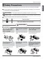 3
3
-
 4
4
-
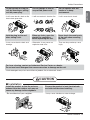 5
5
-
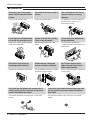 6
6
-
 7
7
-
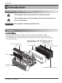 8
8
-
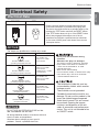 9
9
-
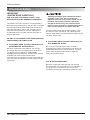 10
10
-
 11
11
-
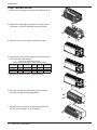 12
12
-
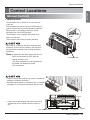 13
13
-
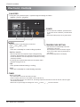 14
14
-
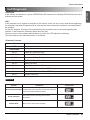 15
15
-
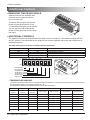 16
16
-
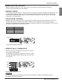 17
17
-
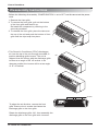 18
18
-
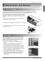 19
19
-
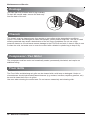 20
20
-
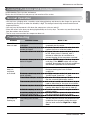 21
21
-
 22
22
-
 23
23
-
 24
24
-
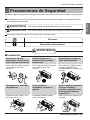 25
25
-
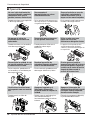 26
26
-
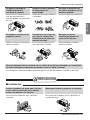 27
27
-
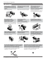 28
28
-
 29
29
-
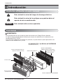 30
30
-
 31
31
-
 32
32
-
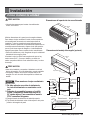 33
33
-
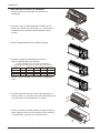 34
34
-
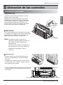 35
35
-
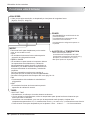 36
36
-
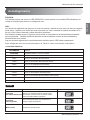 37
37
-
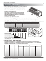 38
38
-
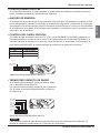 39
39
-
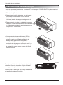 40
40
-
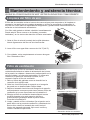 41
41
-
 42
42
-
 43
43
-
 44
44
-
 45
45
-
 46
46


LG LP073HDUC/00 El manual del propietario
- Tipo
- El manual del propietario
- Este manual también es adecuado para
en otros idiomas
- English: LG LP073HDUC/00 Owner's manual
Artículos relacionados
-
LG LP153HD3B/00 El manual del propietario
-
LG Electronics LP073HDUC El manual del propietario
-
-
LG LP073HD2B El manual del propietario
-
LG ARNU18GTLA2.ANWALAT Manual de usuario
-
LG ARNU15GB1G2 Manual de usuario
-
-
LG LT103HNR El manual del propietario
-
 Heat Controller Comfort-Aire BGE-123A El manual del propietario

Otros documentos
-
Friedrich PDE07R3SG PTAC Installation and Operation Manual
-
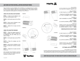 Hubbell TayMac DG28 Guía de instalación
-
TAYMAC DG28 Instrucciones de operación
-
-
Carrier 52C Manual de usuario
-
-
-
Huntleigh FD3 Instructions For Use Manual
