Toro Kawasaki Engine Conversion Kit, Suzuki-Powered Heavy-Duty Lawn Mowers Guía de instalación
- Tipo
- Guía de instalación

FormNo.3355-538RevB
KawasakiEngineConversionKit
ForSuzuki-Poweredheavy-DutyLawnMowers
ModelNo.110-4997
InstallationInstructions
Installation
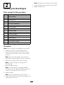
LooseParts
Usethechartbelowtoverifythatallpartshavebeenshipped.
ProcedureDescription
Qty.
Use
1
Nopartsrequired
–
Removetheoldengine.
Beltcover(74-1770)
1
Engine(106-0845)
1
Decal(110-0520)
1
Screws(95-1727)
4
Retainerspacer(103-3795)
1
Tankbracket(106-0908-03)
1
Fueltankcap(93-7198)
1
Screws(104-2628)
3
Fuelhose(109-0296)
1
Fuellter(71-9280)
1
Clamp(2412-98)
4
Fuelhose(109-0650)
1
Cabletie(3290-378)
4
Bladebolt(3212-4)
1
BBCSpacer(107-4058)
1
Springwashers(1-603610)
2
2
Throttlecontrol(114-3488)
1
Installthenewengine.
1
RemovingtheOldEngine
NoPartsRequired
Procedure
Important:Saveallfastenersthatyouremovedfor
reuseunlessotherwisenoted.
1.Drainthefuelfromthefueltank.
2.Removetheoldbeltcoveranddiscardit.
3.Removeanddiscardthethrottlecontrolcable.
4.Removeanddiscardtheoldfuelhose,fuellter,
andclamp.
5.RemovethebladeandtheBBCassembly.
6.Removethebeltfromthedriverpulley;inspectthe
beltforwearandreplaceitifnecessary.
7.Removetheenginemountingbolts.
8.Removetheoldenginefromthemowerhousing.
9.Removethefueltankfromthetankbaseandretain
itforreuse.
10.Replacethefueltankcapwithanewcapprovidedin
thekit;discardtheoldfueltankcap.
11.Removeanddiscardthedischargetunneldoor.
12.Cleanthemowerhousingandcheckitfordamage
andwear.
©2008—TheToro®Company
8111LyndaleAvenueSouth
Bloomington,MN55420
Registeratwww.Toro.com.
OriginalInstructions(EN)
PrintedintheUSA
AllRightsReserved

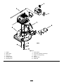
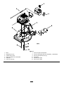
Figure1
1.Engine7.Tankretainer
2.Mowerdeck
8.Fuelhose,fuellter,andclamps
3.Beltcover
9.Enginemountingbolt(4)
4.Fueltankcap
10.Spacer
5.Throttlecontrol
11.Springwasher
6.Dischargedoor12.Bladebolt
2

2
InstallingtheNewEngine
Partsneededforthisprocedure:
1
Beltcover(74-1770)
1
Engine(106-0845)
1
Decal(110-0520)
4
Screws(95-1727)
1
Retainerspacer(103-3795)
1
Tankbracket(106-0908-03)
1
Fueltankcap(93-7198)
3
Screws(104-2628)
1
Fuelhose(109-0296)
1
Fuellter(71-9280)
4
Clamp(2412-98)
1
Fuelhose(109-0650)
4
Cabletie(3290-378)
1
Bladebolt(3212-4)
1
BBCSpacer(107-4058)
2
Springwashers(1-603610)
1
Throttlecontrol(114-3488)
Procedure
Note:RefertoFigure1forinstallingthenewengine.
1.Installthenewdooronthedischargetunnel.
2.Installthefueltank(withthenewfueltankcap)
onthetankbasewiththe2screwsyoupreviously
removed.
Note:Securethetankbracketwith3fasteners
(fromtheloosepartsbag)anduseblueLoctite(242).
3.Installthenewengineonthemowerhousing.
Note:Torquetheenginemountingboltsto
200–250in-lb.
4.InstalltheBBCassembly.
Note:ForinformationoninstallingtheBBC
assembly,refertotheWalkBehindPowerMowerDrive
SystemsServiceManual(FormNo.492-4733).
5.Installtheblade.
Note:Torquethebladeboltto250–320in-lb.
6.Attachthenewfuelhose,fuellter,andclamptothe
engineandthefueltank.
Note:Theshorthoseattachestothefueltank.
7.Installandadjustthenewthrottlecontrolcable.
8.Replacethebeltcover.
3


FormNo.3355-538RevB
KitdeconversiónamotoresKawasaki
CortacéspedesparaserviciopesadoconmotorSuzuki
Nºdemodelo110-4997
Instruccionesdeinstalación
Instalación
Piezassueltas
Utilicelatablasiguienteparavericarquenofaltaningunapieza.
Procedimiento
DescripciónCant.
Uso
1
Nosenecesitanpiezas
–
Retireelmotorantiguo.
Cubiertadelacorrea(74-1770)
1
Motor(106-0845)
1
Pegatina(110-0520)
1
Tornillos(95-1727)
4
Espaciadordelaplacadesujeción
(103-3795)
1
Soportedeldepósito(106-0908-03)
1
Tapóndeldepósitodecombustible
(93-7198)
1
Tornillos(104-2628)
3
Tubodecombustible(109-0296)
1
Filtrodecombustible(71-9280)
1
Abrazadera(2412-98)
4
Tubodecombustible(109-0650)
1
Sujetacables(3290-378)
4
Pernodelacuchilla(3212-4)
1
EspaciadorBBC(107-4058)
1
Arandelasdemuelle(1-603610)
2
2
Controldelacelerador(114-3488)
1
Instaleelmotornuevo.
1
Cómoretirarelmotorantiguo
Nosenecesitanpiezas
Procedimiento
Importante:Guardetodoslosherrajesqueretiró
parasureutilización,amenosqueseespecique
locontrario.
1.Dreneelcombustibledeldepósitodecombustible.
2.Retirelacubiertadelacorreaantiguaydeséchela.
3.Retireydesecheelcabledecontroldelacelerador.
4.Retireydesecheeltubodecombustible,elltrode
combustible,ylaabrazaderaantiguos.
5.RetirelacuchillayelconjuntoBBC.
6.Retirelacorreadelapoleadetransmisión;
inspeccionelacorreaycámbielasiestádesgastada.
7.Retirelospernosdemontajedelmotor.
8.Retireelmotorantiguodelacarcasadelsoplador.
9.Retireeldepósitodecombustibledelsoportedel
depósitoyguárdeloparasuusoposterior.
10.Cambieeltapóndeldepósitodecombustiblepor
eltapónnuevosuministradoconelkit;desecheel
tapóndeldepósitodecombustibleantiguo.
11.Retireydesechelapuertadelconductodedescarga.
12.Limpielacarcasadelcortacéspedycompruebeque
noestádañadanidesgastada.
©2008—TheToro®Company
8111LyndaleAvenueSouth
Bloomington,MN55420
Registresuproductoenwww.Toro.com.
Traduccióndeloriginal(ES)
ImpresoenEE.UU
Reservadostodoslosderechos

Figura1
1.Motor7.Placadesujecióndeldepósito
2.Plataformadecorte8.Tubodecombustible,ltrodecombustible,yabrazaderas
3.Cubiertadelacorrea9.Pernodemontajedelmotor(4)
4.Tapóndeldepósitodecombustible10.Espaciador
5.Acelerador11.Arandelademuelle
6.Puertadedescarga12.Pernodelacuchilla
2

2
Instalacióndelmotornuevo
Piezasnecesariasenestepaso:
1
Cubiertadelacorrea(74-1770)
1
Motor(106-0845)
1
Pegatina(110-0520)
4
Tornillos(95-1727)
1
Espaciadordelaplacadesujeción(103-3795)
1
Soportedeldepósito(106-0908-03)
1
Tapóndeldepósitodecombustible(93-7198)
3
Tornillos(104-2628)
1
Tubodecombustible(109-0296)
1
Filtrodecombustible(71-9280)
4
Abrazadera(2412-98)
1
Tubodecombustible(109-0650)
4
Sujetacables(3290-378)
1
Pernodelacuchilla(3212-4)
1
EspaciadorBBC(107-4058)
2
Arandelasdemuelle(1-603610)
1
Controldelacelerador(114-3488)
Procedimiento
Nota:Paralainstalacióndelmotornuevo,consultela
Figura1.
1.Instalelapuertanuevaenelconductodedescarga.
2.Instaleeldepósitodecombustible(conelnuevo
tapóndeldepósitodecombustible)sobrelabasedel
depósitoconlos2tornillosqueretiróanteriormente.
Nota:Sujeteelsoportedeldepósitocon3herrajes
(delabolsadepiezassueltas)yutiliceLoctiteazul
(242).
3.Retireelmotorantiguodelacarcasadelsoplador.
Nota:Aprietelospernosdemontajedelmotora
22,6–28,2Nm.
4.InstaleelconjuntoBBC.
Nota:Sideseainformaciónsobrelacorrecta
instalacióndelconjuntoBBC,consulteelManualde
mantenimientodesistemasdetransmisiónparacortacéspedes
dirigidosconmotor(ImpresoNº492-4733).
5.Instalelacuchilla.
Nota:Aprieteelpernodelacuchillaa
28,2–36,2Nm.
6.Conecteeltubodecombustible,elltrode
combustible,ylaabrazaderanuevosalmotoryal
depósitodecombustible.
Nota:Eltubocortoseconectaaldepósitode
combustible.
7.Instaleyajusteelnuevocabledecontroldel
acelerador.
8.Vuelvaacolocarlacubiertadelacorrea.
3

-
 1
1
-
 2
2
-
 3
3
-
 4
4
-
 5
5
-
 6
6
-
 7
7
-
 8
8


Toro Kawasaki Engine Conversion Kit, Suzuki-Powered Heavy-Duty Lawn Mowers Guía de instalación
- Tipo
- Guía de instalación
En otros idiomas
Documentos relacionados
-
Toro Kawasaki Engine Conversion Kit, Suzuki-Powered Heavy-Duty Lawn Mowers Guía de instalación
-
-
-
-
-
Toro Lawnmower Manual de usuario
-
-
Toro Recycler Mower Manual de usuario
-
-