Truper Expert COPLA-60X El manual del propietario
- Tipo
- El manual del propietario

15
16
110V
Manual
Plasma Cutter
COPLA-60X
ModelCode
COPLA-60X
Applies for:
17332
60 A
ENGLISH
ESPAÑOL
Read the user’s manual thoroughly
before operating this tool.
CAUTION

2
Technical data
Power requirements
General power tool safety warnings
Safety warnings for the use of plasma
cutters
Parts
Installation
Start up
Maintenance
Symbology
Troubleshooting
Authorized service centers
Warranty policy
3
3
4
5
6
7
8
11
11
12
13
14
ENGLISH
Contents
CAUTION
Keep this manual for future references.
The illustrations in this manual are for reference
only. They might be different from the real tool.
To gain the best performance of
the tool, prolong the duty life,
make the Warranty valid if
necessary, and to avoid hazards
of fatal injuries please read and
understand this Manual before
using the tool.
Use and care recommendations
Perform periodic MAINTENANCE to your machine. (Page 11)
When the machine overheats, the termal protector will activate,
turning the plasma cutter off and turning the LED light ALARM on
Let the plasma cutter cool for 15 minutes and turn it back on.
It is recommended to use a 12 AWG extension cord and connect it to an
INDEPENDENT CHARGING CENTER.

33
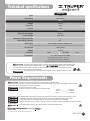
17332
Code
Description
COPLA-60X
Voltage
Power Cord Grips used is: Type “Y”.
Tool Build Quality: Basic Insulation
Thermal insulation on motor winding: Class H
OUTPUT
INPUT
Current 49 A
Frequency 60 Hz
Plasma Cutter
220 V
50 PSI - 80 PSI
IP21S
IP Grade
Current Range
305 V c.c.
Open Circuit Voltage
1”
Maximum Cutting Capacity
Air Pressure
31.74 lb
Weight
3/4”
Ideal Cutting Capacity
Work Cycle
Insulation Class I
20 A - 60 A
3G - 6 mm2 with 221 °F insulation
Conductors
30 % 3 minutes’ work per 7 minutes’ rest.
The specified output values are given in a 68 °F temperature. With higher temperatures, the work cycle can be reduced.
Power Requirements
Technical specifications
ENGLISH
WARNING
WARNING Avoid the risk of electric shock or severe injury. When the power cable gets damaged
it should only be replaced by the manufacturer or at a Authorized Service Center.
The build quality of the electric insulation is altered if spills or liquid gets into the tool while in use.
Do not expose to rain, liquids and/or dampness.
Before gaining access to the terminals all power sources should be disconnected.
The tool shall be grounded while in use to prevent an electric shock.
The cutter shall be installed as close as possible to the mains power supply. Check the power supply carries the same
voltage than the one indicated in the motor nameplate.
This tool has to be grounded.
The power cables are coded with the following colors:
• - If using the cutter together with more tools having the same ground, connect in parallel, never making a series.
• The ground conductor cable gauge shall not be a lower gauge than the power supply cable.
• Connection to the power supply shall be carried out by a professional electrician.
• Double check the input connection voltage shown in the plasma cutter nameplate matches the power
supply voltage.
• The power supply gauge shall comply with the following requirements
CAUTION
CAUTION
CAUTION
* Fuse fusion current is double than its rated current.
Fuse (rated working current)
Electric Wire 55 A (*)
6 mm2
CAUTION
CAUTION GREEN GROUND
WHITE CURRENT
BLACK CURRENT
WARNING
WARNING

4ENGLISH
General Power Tools
Safety Warnings
Work area
Keep your work area clean, and well lit.
Cluttered and dark areas may cause accidents.
Never use the tool in explosive atmospheres, such as in the
presence of flammable liquids, gases or dust.
Sparks generated by power tools may ignite the flammable material.
Keep children and bystanders at a safe distance while
operating the tool.
Distractions may cause loosing control.
Electrical Safety
The tool plug must match the power outlet. Never modify
the plug in any way. Do not use any adapter plugs with
grounded power tools.
Modified plugs and different power outlets increase the risk of electric shock.
Avoid body contact with grounded surfaces, such as pipes,
radiators, electric ranges and refrigerators.
The risk of electric shock increases if your body is grounded.
Do not expose the tool to rain or wet conditions.
Water entering into the tool increases the risk of electric shock.
Do not force the cord. Never use the cord to carry, lift or unplug
the tool. Keep the cord away from heat, oil, sharp edges or
moving parts.
Damaged or entangled cords increase the risk of electric shock.
When operating a tool outdoors, use an extension cord suitable
for outdoor use.
Using an adequate outdoor extension cord reduces the risk of electric shock.
If operating the tool in a damp location cannot be avoided, use
a ground fault circuit interrupter (GFCI) protected supply.
Using a GFCI reduces the risk of electric shock.
Personal safety
Stay alert, watch what you are doing and use common sense
when operating a tool. Do not use a power tool while you are
tired or under the influence of drugs, alcohol or medication.
A moment of distraction while operating the tool may result in personal injury.
Use personal protective equipment. Always wear eye
protection.
Protective equipment such as safety glasses, anti-dust mask, non-skid shoes,
hard hats and hearing protection used in the right conditions significantly
reduce personal injury.
Prevent unintentional starting up. Ensure the switch is in the
“OFF” position before connecting into the power source and /
or battery as well as when carrying the tool.
Transporting power tools with the finger on the switch or connecting power
tools with the switch in the “ON” position may cause accidents.
Remove any wrench or vice before turning the power tool on.
Wrenches or vices left attached to rotating parts of the tool may result in personal
injury.
Do not overreach. Keep proper footing and balance at all times.
This enables a better control on the tool during unexpected situations.
Dress properly. Do not wear loose clothing or jewelry.
Keep hair, clothes and gloves away from the moving parts.
Loose clothes or long hair may get caught in moving parts.
If you have dust extraction and recollection devices connected
onto the tool, inspect their connections and use them correctly.
Using these devices reduce dust-related risks.
Power Tools Use and Care
Do not force the tool. Use the adequate tool for your
application.
The correct tool delivers a better and safer job at the rate for which it was designed.
Do not use the tool if the switch is not working properly.
Any power tool that cannot be turned ON or OFF is dangerous and should be
repaired before operating.
Disconnect the tool from the power source and / or battery
before making any adjustments, changing accessories or
storing.
These measures reduce the risk of accidentally starting the tool.
Store tools out of the reach of children. Do not allow persons
that are not familiar with the tool or its instructions to
operate the tool.
Power tools are dangerous in the hands of untrained users.
Service the tool. Check the mobile parts are not misaligned or
stuck. There should not be broken parts or other conditions that
may affect its operation. Repair any damage before using
the tool.
Most accidents are caused due to poor maintenance to the tools.
Keep the cutting accessories sharp and clean.
Cutting accessories in good working conditions are less likely to bind and are
easier to control.
Use the tool, components and accessories in accordance with
these instructions and the projected way to use it for the type of
tool when in adequate working conditions.
Using the tool for applications different from those it was designed for, could
result in a hazardous situation.
Service
Repair the tool in a Authorized Service Center
using only identical spare parts.
This will ensure that the safety of the power tool is maintained.
WARNING! Read carefully all safety warnings and instructions listed below. Failure to comply with any of
these warnings may result in electric shock, fire and / or severe damage. Save all warnings and instructions for
future references.

5
• Vapors and gasses produced while cutting are
hazardous to your health. Work in ventilated areas or using
adequate ventilation systems.
• Do not breath in smoke or gases produced in
the cutting process. Keep head away from fumes.
• If ventilation is poor, wear an adequate
autonomous breathing devise. Protection gases generated while
cutting may displace air and cause fatal accidents.
• Do not operate the equipment close to
degreasers, cleaner or aerosol cans. Heat and radiation generated
by the cutting process may react with vapors and form toxic gas.
• Prevent cutting lead, zinc or cadmium covered
metal. These materials generate toxic gases. Remove the covering
out from the cutting area, make sure the area is well ventilated or
use an adequate autonomous breathing device.
• Wear a welder helmet to protect your
eyes and face when working with the equipment. Assure
the helmet shadow lens is the right one for the cutting process
Using shadow 6 and / or 7 is recommended.
• Use special hide gloves specially designed
for cutting as well as dungarees and leather spats.
• Wear robust material clothes and long sleeves made of fire-resistant
materials, such as wool or hide.
• Use special screens or curtains to insulate the work place to protect
the passersby from sparks, flare and slag generated during the cutting
process.
• The bench or work table where the work piece rest shall have
orifices or slots that will easily let got through residues originated in
the cutting process.
Protection Equipment
CAUTION
CAUTION
CAUTION
WARNING
DANGER
• Double check the input and output cable are
securely connected and in good repair (check and eliminate any
possibility of short circuit).
• Confirm the equipment ground
connection is reliable.
• The welding power sources are not adequate for
using in rain or snow.
• Keep yourself insulated from the work piece and
ground, stepping on insulated and dry mats.
• For no reason at all touch both poles in the
equipment circuit (torch electrode and work piece).
• Do not try to adjust the equipment current when
cutting.
• Connect the ground clamp to the work piece as
close as possible from the cutting zone to prevent the current flowing
long distances and eliminate the possibility of a short circuit.
• Before operating the equipment, the work piece
shall make contact with the ground connection clamp. do not
disconnect until finishing the cut. otherwise the user may receive an
electric discharge and severe injuries.
• Disconnect the equipment from the power source
before carrying out maintenance.
• Electric shock risk! An electric shock caused by the
torch may cause death!
To Prevent Electric Shock
• Always have a fire extinguisher handy.
• There shall be no flammable or
explosive material in the work area (not less than 36 ft away).
Do not cut in places where the sparks may reach of fall on
flammable or explosive materials.
• Sparks produced while cutting may cause
explosion or fire.
To Prevent Fire
CAUTION
CAUTION
CAUTION
CAUTION
CAUTION
CAUTION
DANGER
WARNING
WARNING
WARNING
WARNING
WARNING
WARNING
To Prevent Health Risks
WARNING
WARNING
• Risk generated by the arc:
Arc radiation may burn eyes and damage skin.
Wear protection helmet and safety goggles.
Use ears protection and protective clothes that cover skin up to the
neck. Wear complete body protection garments.
• Risk produced by electro-magnetic field:
Cutting current produces an electro-magnetic field.
The operator shall not use the power source if having medical
implants. Never roll the equipment cables around the body. Place
together and parallel both cables connected to the equipment so that
the fields of each one will counteract.
• Never allow unexperienced people dismount or
regulate the equipment.
• Double check that both the operator and the
equipment are away from the sparks flow and residues originated
during the cutting process.
• The cutter shall be operated in a place that is protected from sun
and rain, away from places where violent vibrations occur.
• The cutter shall be stored away in a humidity free area with -13 °F
to 131 °F temperature range.
• To prevent rollover, the equipment shall be inclined
10° maximum.
• There shall be 12” space around the equipment to receive good
ventilation.
• Environment temperature range when cutting:
14 °F a 104 °F
• Make sure no foreign metal object is inside the
equipment.
• Any problem with the equipment the operator
cannot solve making adjustments for a good cutting process shall be
solved in a Authorized Service Center. For no
reason at all the operator shall try to open the equipment cover to
carry out any type of maintenance.
• Never point the torch nowhere in your body.
• Do not touch the work piece while cutting.
• Do not fold the torch cable. It damages the air hose.
• Nobody but the operator shall have access to the work site.
• Always turn down the power supply before carrying out repairs,
moving the machine or install accessories (torch, electrode, nozzle,
ground clamp, etc.).
• Never remove slag from the torch hitting a hard object.
To Prevent Injuries and Accidents
CAUTION
CAUTION
CAUTION
WARNING
WARNING
WARNING
WARNING
WARNING
Safety Warnings
for Plasma cutter
ENGLISH

15
16
110V
Air
inlet hose
Clamp to
ground the
work piece
6
Parts
Gauge
Current
Control
Power
Indicator
Air Low
Level
Indicator
Cutting
Current
Indicator
Ventilation
Slots
Torch Fast
Connection
Torch
Torch
Cap
Trawl
Guide
Air
Line
Current
Connectors
Trigger
Switch
Trigger
Lock
Electrode
Wrench
Torch
Head
Electrode and
Spare Electrode
Interchangeable
nozzles (x2)
Diffuser
Torch
Terminal
Clamp
Terminal
Fast
Connection
ON
switch
Air
Intake
Pressure
Regulator
Carrying
Handle
Activated Thermal
Protection Indicator
ENGLISH
Rotameter

15
16
110V
E
B
7
Installation
C
Torch
Power Supply
Compressor
50 PSI - 80 PSI
Moist
filter
To prevent electric shock read the
information in the “Power Requirements” section in pages 3
and 5.
• Connect the power cable (E) to the 220 V work voltage.
Before using, the equipment shall be
correctly grounded. No not remove the ground cable.
Otherwise it causes severe body injuries.
Make sure the torch is
correctly assembled before connecting into the
equipment.
• Assemble all the torch parts in the same order
as shown in the graph.
• When it is assembled connect the torch to the
front panel terminal (A).
• Unroll the torch hose completely.
WARNING
D
A
Compressed Air Supply
• The plasma cutter requires a
50 PSI - 80 PSI air compressor.
• Use a moisture filter between the
compressor and the plasma cutter to send totally dry air to
the torch. Otherwise, the cut quality will be seriously
diminished.
• Connect the air-line of the moist filter to the cutter air inlet
in the back panel of the plasma cutter (D).
CAUTION
CAUTION
CAUTION
CAUTION
• Insert the grounding clamp fast connection. Turn one
quarter of a turn in a clockwise direction to secure it in
the front panel terminal (B).
• Connect the ground clamp (C) to the piece or work
bench.
If the ground clamp is not making contact
correctly, the piece will not get cut because the cutter
will only be operating with the pilot flame.
NOTE
Grounding Clamp
ENGLISH

• Double check the plasma cutter is connected right in good working
conditions as described in page 7. Make sure you follow the safety Warnings in pages 4
and 5.
• Turn ON the cutter switch
(A)
to see if the operation is normal. If so, the fan will start
and the power indicating light will be ON
(B)
.
• Adjust the pressure using the manometer 344 kPa - 551 kPa (50 PSI - 80 PSI). Once
the working pressure is reached, validate the adjustment with the rotameter. If the inlet
pressure is lower, the arc when cutting will be intermittent and the cut quality will be
reduced. In the event, there is no air in the line, the low air level indicating light
(C)
will
be ON and the cutter will not generate the plasma arc to make the cut.
Note: If you need a quick validation of the air pressure at the work site, use the
included rotameter as indicated below:
• Place the torch face up as shown in figure
(H)
.
• Press the torch trigger to activate the flow of air.
When pressing the trigger, the torch pilot flame will ignite. Do not
approach any part of your body to the torch while the pilot flame is on. Keep the trigger
pressed for a few seconds until the pilot flame goes out, you will perceive that air is still
coming out of the torch.
• Press the rotameter firmly onto the torch nozzle.
The adjustment should be similar to that reached in the initial validation, otherwise
make the corresponding adjustment on your compressor and/or cutter knob.
• Release the trigger lock
(E)
. The plasma cutter is ready to operate.
H
8
Start Up
Air pressure adjustment
CAUTION
ENGLISH
WARNING
15
16
110V
15
16
110V
A
E
G
F
C
B
D

9
Start Up
• The cut shall always start in the work piece edge. Move
the torch in one direction only unless piercing is required.
• Always keep some space between the
nozzle and the work piece. Use the cutting guide
(F)
. The
nozzle contact onto the work piece may cause the nozzle
gets stuck and interfere with the cutting movement,
getting a faulty cut.
• Keep the torch tip perpendicular to the work piece.
Observe and confirm the puddle moves along the cutting
line.
• Do not press the trigger intermittently. It damages the
torch components and the work piece.
• Every 4 or 8 hours check the moist
filter
(G)
and remove the excessive humidity. Too much
moist in the cutter or the torch may cause problems in
the operation.
General Considerations
1. Upon pressing and releasing the torch trigger, air will
start coming out without generating any arc.
2. Keep pressed the torch trigger without approaching it to
the work piece and a pilot flame will be started. This flame
is no capable of making an effective cut, however, it
prevents the material to disperse when tuning ON the
flame close to the piece.
3. Upon putting the torch near the work piece with the
pilot flame ON, automatically a plasma arc is generated
and you can start cutting.
Pilot Flame
CAUTION
CAUTION
ENGLISH

10
Start Up
• When pushing the trigger both current and compressed air reach the torch head where
air changes status, from gas to plasma when interacting with the electric arc.
• The cut starts when the plasma is driven out through the torch nozzle attracted by the work piece grounded with the
clamp. Speed and temperature with which plasma is driven out vaporize the metal in the work piece.
• Use the cut guide to prevent making contact between
the nozzle and the work piece. Otherwise, the accidental
contact may ruin the nozzle, lessens the useful life of the
torch components and / or produces a bad finish in the
cut.
• Approach the nozzle to the work piece in the point
where the cut will start.
• Support the cut guide in the work piece (A) and make
sure the torch tip is perpendicular to the work piece.
• Press the torch switch to expel the plasma and starts to
cut.
• Move the torch through the cut line with constant
speed.
• Cutting speed depends in the relationship between the
material thickness and the current selected in the front
panel of the cutter. When the torch is displaced fast or the
current is low, it may not be enough to cut thick materials
but adequate for thinner materials.
• When the cutting process is finished, turn OFF the torch
and the arc pilot stops.
• Approach the nozzle to the wire of the mesh where you
want to start cutting but without touching it. Remember
that the accidental contact may ruin the nozzle, shorten
the useful life of the torch components and / or produce
a defective finish in the cut.
• Press the torch switch to drive out the plasma and start
cutting.
• Release the torch trigger immediately after cutting the
mesh.
• Repeat the procedure in the next mesh wire.
• Do not try to cut the mesh with only one cut without
releasing the torch trigger. Keeping it ON unnecessarily
reduces the useful life of the torch electrode and the
nozzle.
Cutting a Metal Sheet
Cutting Capacity
Cutting Metal Mesh
A
Thickness Current Air Pressure Air Flow Cutting Speed
Carbon
Steel
Stainless
Steel
0.04” - 0.12”
0.16” - 0.24”
0.3” - 0.4”
20 A - 60 A
30 A - 60 A
35 A - 60 A
20 A - 60 A
30 A - 60 A
35 A - 60 A
65 PSI
65 PSI
73.9 Gal/min
73.9 Gal/min
14”/min - 67”/min
9.7”/min - 39”/min
5.7”/min - 27”/min
0.47” - 0.6” 40 A - 60 A 3”/min - 16”/min
0.8” - 1” 45 A - 60 A 2.8”/min - 6”/min
12”/min - 58”/min
8.2”/min - 33”/min
4.5”/min - 17.6”/min
0.04” - 0.12”
0.16” - 0.24”
0.3” - 0.4”
40 A - 60 A 2”/min - 12.7”/min0.47” - 0.6”
ENGLISH

• Proper use and regular cleansing lengthen the useful life of the plasma cutter.
• Only certified personnel shall carry out repairs. We recommend visiting a
Authorized Service Center to repair the plasma cutter and purchase supplies or accessories.
CAUTION
Regular Maintenance
• Clean the dust from the equipment with compressed air.
If there is too much dust clean immediately. Under normal
conditions, clean once yearly. If the equipment is exposed
to too much dust, cleansing shall be carried out every
three months.
• Together with cleansing make a checkup to assure there
are no loose components or parts in the equipment.
• Keep the plasma cutter cables in good repair.
• Connections shall be checked before each use.
Electrode Replacement
1. The cutter electrode has a useful life ideal to cut up to
66 ft if used in the maximum capacity.
2. When the plasma arc flame is showing a greenish tone,
means the electrode is about to end its useful life and it is
advisable to replace it.
3. As a better reference, the electrode shows an insert in
the center of the tip that wears out with use generating an
orifice when its depth is larger than 0,031”
When using electrodes whose insert has a
larger depth, will cause overheating in the torch and will
damage it completely.
NOTE
Storage
• If the equipment is going to be stored for a long period
of time, it shall be kept in a dry and well ventilated place to
prevent the entrance moist and generate oxide or toxic
gases. Storage temperature varies from -13 °F a 131 °F
and relative humidity shall not be over 90%.
11
Maintenance
Symbology
ENGLISH
DC symbol
Plasma cut
Input circuit, single-phase alternating current and rated frequency symbol
Duty cycle symbol (service factor)
Nominal welding current symbol
Conventional load voltage symbol
Rated open circuit voltage
Rated power voltage
Maximum rated current
Maximum effective current
Protection degree (solid objects and water submersion)
Transformer - single-phase
AC symbol
I2
U2
U0... V
U1... V
I1 max... A
I1 eff... A
IP
1
~
60 Hz
X
1˜

• Connect the supply cable into a 220 V outlet.
• Go to a Authorized Service Center
to repair.
• Go to a Authorized Service Center
to repair.
• Go to a Authorized Service Center
to repair.
• Go to a Authorized Service Center
to repair.
• Examine and remove the blockage.
• Go to a Authorized Service Center
to repair.
• Check the connections. Turn ON the compressor.
• Go to a Authorized Service Center
to repair.
• Remove the blockage, clean and stretch the hoses.
• Go to a Authorized Service Center
to repair.
• Set the nozzle close to the work piece.
• Clean or replace the nozzle.
• Replace the electrode.
• Examine and clean or replace the torch components.
• Set correctly the ground clamp in the work piece.
• Set the ground clamp correctly in the work piece.
• Go to a Authorized Service Center
to repair.
• Verify the pneumatic installation and the compressor.
• Connect the supply cable into a 220 V outlet.
• Replace the fuse.
• Go to a Authorized Service Center
to repair.
• Check the power supply voltage with a voltmeter.
• Wait until the equipment cools down.
• Go to a Authorized Service Center
to repair.
The power indicating
light is not ON after
turning ON the
equipment.
The fan is not working
after tuning ON the
equipment.
The low-pressure
indicator is ON.
The torch is not cutting
or there is not plasma
out.
There is not response
when pressing the
torch trigger.
No response after
starting the
equipment.
The protection
indicating light is ON.
• Input voltage is not 220 V
• The light is not working .
• The fuse is blown.
• The power supply switch is not working.
• The control dashboard or the cutter are
damaged.
• The fan is blocked.
• The fan is damaged.
• The transformer is damaged.
• There is no compressed air entry.
• The air valve is closed or broken.
• The air or gas pressure circuit is blocked.
• The air or gas valve is damaged.
• The space between the nozzle and the
work piece is too big.
• Nozzle is dirty, damaged or blocked.
• Worn electrode.
• Torch components are dirty or damaged.
• Grounding clamp is positioned wrong.
• The grounding clamp is not set correctly.
• The trigger, dashboard or transformer are
damaged.
• There is no air in the pneumatic line.
• The feeding cable is not connected
properly.
• Damaged fuse.
• Damaged switch, dashboard or
transformer.
• The power supply configuration is
incorrect.
• Overheating due to excessive work cycle.
• The thermal relay is damaged or the main
dashboard is out of order.
Problem Cause Solution
If the problems persist despite making the recommended corrective actions or there are other problems contact a
Authorized Service Center.
12 ENGLISH
Troubleshooting

In the event of any problem contacting a Truper Authorized Service Center, please see our webpage www.truper.com
to get an updated list, or call our toll-free numbers 800 690-6990 or 800-018-7873 to get information about the
nearest Service Center.
AGUASCALIENTES
BAJA
CALIFORNIA
BAJA
CALIFORNIA SUR
CAMPECHE
CHIAPAS
CHIHUAHUA
CIUDAD DE
MÉXICO
COAHUILA
COLIMA
DURANGO
ESTADO DE
MÉXICO
GUANAJUATO
GUERRERO
HIDALGO
JALISCO
MICHOACÁN
MORELOS
NAYARIT
NUEVO LEÓN
OAXACA
PUEBLA
QUERÉTARO
QUINTANA ROO
SAN LUIS
POTOSÍ
SINALOA
SONORA
TABASCO
TAMAULIPAS
TLAXCALA
VERACRUZ
YUCATÁN
DE TODO PARA LA CONSTRUCCIÓN
GRAL. BARRAGÁN #1201, COL. GREMIAL, C.P. 20030,
AGUASCALIENTES, AGS. TEL.: 449 994 0537
SUCURSAL TIJUANA
AV. LA ENCANTADA, LOTE #5, PARQUE INDUSTRIAL EL
FLORIDO II, C.P 22244, TIJUANA, B.C.
TEL.: 664 969 5100
FIX FERRETERÍAS
FELIPE ÁNGELES ESQ. RUIZ CORTÍNEZ S/N, COL. PUEBLO
NUEVO, C.P. 23670, CD. CONSTITUCIÓN, B.C.S.
TEL.: 613 132 1115
TORNILLERÍA Y FERRETERÍA AAA
AV. ÁLVARO OBREGÓN #324, COL. ESPERANZA
C.P. 24080 CAMPECHE, CAMP. TEL.: 981 815 2808
FIX FERRETERÍAS
AV. CENTRAL SUR #27, COL. CENTRO, C.P. 30700,
TAPACHULA, CHIS. TEL.: 962 118 4083
SUCURSAL CHIHUAHUA
AV. SILVESTRE TERRAZAS #128-11, PARQUE INDUSTRIAL
BAFAR, CARRETERA MÉXICO CUAUHTÉMOC, C.P. 31415,
CHIHUAHUA, CHIH. TEL. 614 434 0052
FIX FERRETERÍAS
EL MONSTRUO DE CORREGIDORA, CORREGIDORA # 35,
COL. CENTRO, C.P. 06060, CUAUHTÉMOC, CDMX.
TEL: 55 5522 5031 / 5522 4861
SUCURSAL TORREÓN
CALLE METAL MECÁNICA #280, PARQUE INDUSTRIAL
ORIENTE, C.P. 27278, TORREÓN, COAH.
TEL.: 871 209 68 23
BOMBAS Y MOTORES BYMTESA DE MANZANILLO
BLVD. MIGUEL DE LA MADRID #190, COL. 16 DE
SEPTIEMBRE, C.P. 28239, MANZANILLO, COL.
TEL.: 314 332 1986 / 332 8013
TORNILLOS ÁGUILA, S.A. DE C.V.
MAZURIO #200, COL. LUIS ECHEVERRÍA, DURANGO,
DGO.TEL.: 618 817 1946 / 618 818 2844
SUCURSAL CENTRO JILOTEPEC
PARQUE INDUSTRIAL # 1, COL. PARQUE INDUSTRIAL
JILOTEPEC, JILOTEPEC, EDO. DE MÉX. C.P. 54257
TEL: 761 782 9101 EXT. 5728 Y 5102
CÍA. FERRETERA NUEVO MUNDO S.A. DE C.V.
AV. MÉXICO - JAPÓN #225, CD. INDUSTRIAL, C.P. 38010,
CELAYA, GTO. TEL.: 461 617 7578 / 79 / 80 / 88
CENTRO DE SERVICIO ECLIPSE
CALLE PRINCIPAL MZ.1 LT. 1, COL. SANTA FE, C.P. 39010,
CHILPANCINGO, GRO. TEL.: 747 478 5793
FERREPRECIOS S.A. DE C.V.
LIBERTAD ORIENTE #304 LOCAL 30, INTERIOR DE PASAJE
ROBLEDO, COL. CENTRO, C.P. 43600, TULANCINGO,
HGO. TEL.: 775 753 6615 / 775 753 6616
SUCURSAL GUADALAJARA
AV. ADOLFO B. HORN # 6800, COL: SANTA CRUZ DEL
VALLE, C.P.: 45655, TLAJOMULCO DE ZUÑIGA, JAL.
TEL.: 33 3606 5285 AL 90
FIX FERRETERÍAS
AV. PASEO DE LA REPÚBLICA #3140-A, COL.
EX-HACIENDA DE LA HUERTA, C.P. 58050, MORELIA,
MICH. TEL.: 443 334 6858
FIX FERRETERÍAS
CAPITÁN ANZURES #95, ESQ. JOSÉ PERDIZ, COL.
CENTRO, C.P. 62740, CUAUTLA, MOR.
TEL.: 735 352 8931
HERRAMIENTAS DE TEPIC
MAZATLAN #117, COL. CENTRO, C.P. 63000, TEPIC, NAY.
TEL.: 311 258 0540
SUCURSAL MONTERREY
CARRETERA LAREDO #300, 1B MONTERREY PARKS,
COLONIA PUERTA DE ANÁHUAC, C.P. 66052, ESCOBEDO,
NUEVO LEÓN, TEL.: 81 8352 8791 / 81 8352 8790
FIX FERRETERÍAS
AV. 20 DE NOVIEMBRE #910, COL. CENTRO, C.P. 68300,
TUXTEPEC, OAX. TEL.: 287 106 3092
SUCURSAL PUEBLA
AV PERIFÉRICO #2-A, SAN LORENZO ALMECATLA,
C.P. 72710, CUAUTLACINGO, PUE.
TEL.: 222 282 8282 / 84 / 85 / 86
ARU HERRAMIENTAS S.A DE C.V.
AV. PUERTO DE VERACRUZ #110, COL. RANCHO DE
ENMEDIO, C.P. 76842, SAN JUAN DEL RÍO, QRO.
TEL.: 427 268 4544
FIX FERRETERÍAS
CARRETERA FEDERAL MZ. 46 LT. 3 LOCAL 2, COL EJIDAL,
C.P. 77710 PLAYA DEL CARMEN, Q.R.
TEL.: 984 267 3140
FIX FERRETERÍAS
AV. UNIVERSIDAD #1850, COL. EL PASEO, C.P. 78320,
SAN LUIS POTOSÍ, S.L.P. TEL.: 444 822 4341
SUCURSAL CULIACÁN
AV. JESÚS KUMATE SUR #4301, COL. HACIENDA DE LA
MORA, C.P. 80143, CULIACÁN, SIN.
TEL.: 667 173 9139 / 173 8400
FIX FERRETERÍAS
CALLE 5 DE FEBRERO #517, SUR LT. 25 MZ. 10, COL.
CENTRO, C.P. 85000, CD. OBREGÓN, SON.
TEL.: 644 413 2392
SUCURSAL VILLAHERMOSA
CALLE HELIO LOTES 1, 2 Y 3 MZ. #1, COL. INDUSTRIAL,
2A ETAPA, C.P. 86010, VILLAHERMOSA, TAB.
TEL.: 993 353 7244
VM ORINGS Y REFACCIONES
CALLE ROSITA #527 ENTRE 20 DE NOVIEMBRE Y GRAL.
RODRÍGUEZ, FRACC. REYNOSA, C.P. 88780, REYNOSA,
TAMS. TEL.: 899 926 7552
SERVICIOS Y HERRAMIENTAS INDUSTRIALES
PABLO SIDAR #132, COL . BARRIO DE SAN BARTOLOMÉ,
C.P. 90970, SAN PABLO DEL MONTE, TLAX.
TEL.: 222 271 7502
LA CASA DISTRIBUIDORA TRUPER
BLVD. PRIMAVERA. ESQ. HORTENSIA S/N, COL.
PRIMAVERA C.P. 93308, POZA RICA, VER.
TEL.: 782 823 8100 / 826 8484
SUCURSAL MÉRIDA
CALLE 33 #600 Y 602, LOCALIDAD ITZINCAB Y MULSAY,
MPIO. UMÁN, C.P. 97390, MÉRIDA, YUC.
TEL.: 999 912 2451
13
ENGLISH
Authorized Service Centers

Warranty. Duration: 5 year. Coverage: parts, components and workmanship against manufacturing or operating
defects, except if used under conditions other than normal; when it was not operated in accordance with the
instructive; was altered or repaired by personnel not authorized by Truper®. To make the warranty valid, only
present the product in the establishment where you bought it or in Corregidora 35, Centro, Cuauhtémoc, CDMX,
06060, where you can also purchase parts, components, consumables and accessories. The costs of
transportation of the product that derive from its fulfillment of its service network are included. Truper will not
require any proof of purchase to make the warranty effective. Phone number 800-018-7873. Made in China.
Imported by Truper, S.A. de C.V. Parque Industrial 1, Parque Industrial Jilotepec, Jilotepec, Edo. de Méx.
C.P. 54257, Phone number 761 782 9100.
14 ENGLISH www.truper.com
01-2023
Warranty
policy
Code Model Brand
Stamp of the business. Delivery date:
17332 COPLA-60X

Garantía. Duración: 5 años. Cobertura: piezas, componentes y mano de obra contra defectos de fabricación o
funcionamiento, excepto si se usó en condiciones distintas a las normales; cuando no fue operado conforme
instructivo; fue alterado o reparado por personal no autorizado por Truper®. Para hacer efectiva la garantía
únicamente presente el producto en el establecimiento donde lo compró o en Corregidora 35, Centro,
Cuauhtémoc, CDMX, 06060, donde también podrá adquirir partes, componentes, consumibles y accesorios.
Incluye los gastos de transportación del producto que deriven de su cumplimiento de su red de servicio. Truper
no solicitará ningún tipo de comprobante de pago para hacer efectiva la garantía. Tel. 800-018-7873. Made
in/Hecho en China. Importador Truper, S.A. de C.V. Parque Industrial 1, Parque Industrial Jilotepec, Jilotepec, Edo.
de Méx. C.P. 54257, Tel. 761 782 9100.
17332 COPLA-60X
14 ESPAÑOL
Póliza de
Garantía
www.truper.com
01-2023
Código Modelo Marca
Sello del establecimiento comercial. Fecha de entrega:

En caso de tener algún problema para contactar un Centro de Servicio Autorizado Truper
®
consulte nuestra página
www.truper.com donde obtendrá un listado actualizado, o llame al: 800 690 6990 u 800-018-7873 donde le
informarán cuál es el Centro de Servicio más cercano.
AGUASCALIENTES
BAJA
CALIFORNIA
BAJA
CALIFORNIA SUR
CAMPECHE
CHIAPAS
CHIHUAHUA
CIUDAD DE
MÉXICO
COAHUILA
COLIMA
DURANGO
ESTADO DE
MÉXICO
GUANAJUATO
GUERRERO
HIDALGO
JALISCO
MICHOACÁN
MORELOS
NAYARIT
NUEVO LEÓN
OAXACA
PUEBLA
QUERÉTARO
QUINTANA ROO
SAN LUIS
POTOSÍ
SINALOA
SONORA
TABASCO
TAMAULIPAS
TLAXCALA
VERACRUZ
YUCATÁN
DE TODO PARA LA CONSTRUCCIÓN
GRAL. BARRAGÁN #1201, COL. GREMIAL, C.P. 20030,
AGUASCALIENTES, AGS. TEL.: 449 994 0537
SUCURSAL TIJUANA
AV. LA ENCANTADA, LOTE #5, PARQUE INDUSTRIAL EL
FLORIDO II, C.P 22244, TIJUANA, B.C.
TEL.: 664 969 5100
FIX FERRETERÍAS
FELIPE ÁNGELES ESQ. RUIZ CORTÍNEZ S/N, COL. PUEBLO
NUEVO, C.P. 23670, CD. CONSTITUCIÓN, B.C.S.
TEL.: 613 132 1115
TORNILLERÍA Y FERRETERÍA AAA
AV. ÁLVARO OBREGÓN #324, COL. ESPERANZA
C.P. 24080 CAMPECHE, CAMP. TEL.: 981 815 2808
FIX FERRETERÍAS
AV. CENTRAL SUR #27, COL. CENTRO, C.P. 30700,
TAPACHULA, CHIS. TEL.: 962 118 4083
SUCURSAL CHIHUAHUA
AV. SILVESTRE TERRAZAS #128-11, PARQUE INDUSTRIAL
BAFAR, CARRETERA MÉXICO CUAUHTÉMOC, C.P. 31415,
CHIHUAHUA, CHIH. TEL. 614 434 0052
FIX FERRETERÍAS
EL MONSTRUO DE CORREGIDORA, CORREGIDORA # 35,
COL. CENTRO, C.P. 06060, CUAUHTÉMOC, CDMX.
TEL: 55 5522 5031 / 5522 4861
SUCURSAL TORREÓN
CALLE METAL MECÁNICA #280, PARQUE INDUSTRIAL
ORIENTE, C.P. 27278, TORREÓN, COAH.
TEL.: 871 209 68 23
BOMBAS Y MOTORES BYMTESA DE MANZANILLO
BLVD. MIGUEL DE LA MADRID #190, COL. 16 DE
SEPTIEMBRE, C.P. 28239, MANZANILLO, COL.
TEL.: 314 332 1986 / 332 8013
TORNILLOS ÁGUILA, S.A. DE C.V.
MAZURIO #200, COL. LUIS ECHEVERRÍA, DURANGO,
DGO.TEL.: 618 817 1946 / 618 818 2844
SUCURSAL CENTRO JILOTEPEC
PARQUE INDUSTRIAL # 1, COL. PARQUE INDUSTRIAL
JILOTEPEC, JILOTEPEC, EDO. DE MÉX. C.P. 54257
TEL: 761 782 9101 EXT. 5728 Y 5102
CÍA. FERRETERA NUEVO MUNDO S.A. DE C.V.
AV. MÉXICO - JAPÓN #225, CD. INDUSTRIAL, C.P. 38010,
CELAYA, GTO. TEL.: 461 617 7578 / 79 / 80 / 88
CENTRO DE SERVICIO ECLIPSE
CALLE PRINCIPAL MZ.1 LT. 1, COL. SANTA FE, C.P. 39010,
CHILPANCINGO, GRO. TEL.: 747 478 5793
FERREPRECIOS S.A. DE C.V.
LIBERTAD ORIENTE #304 LOCAL 30, INTERIOR DE PASAJE
ROBLEDO, COL. CENTRO, C.P. 43600, TULANCINGO,
HGO. TEL.: 775 753 6615 / 775 753 6616
SUCURSAL GUADALAJARA
AV. ADOLFO B. HORN # 6800, COL: SANTA CRUZ DEL
VALLE, C.P.: 45655, TLAJOMULCO DE ZUÑIGA, JAL.
TEL.: 33 3606 5285 AL 90
FIX FERRETERÍAS
AV. PASEO DE LA REPÚBLICA #3140-A, COL.
EX-HACIENDA DE LA HUERTA, C.P. 58050, MORELIA,
MICH. TEL.: 443 334 6858
FIX FERRETERÍAS
CAPITÁN ANZURES #95, ESQ. JOSÉ PERDIZ, COL.
CENTRO, C.P. 62740, CUAUTLA, MOR.
TEL.: 735 352 8931
HERRAMIENTAS DE TEPIC
MAZATLAN #117, COL. CENTRO, C.P. 63000, TEPIC, NAY.
TEL.: 311 258 0540
SUCURSAL MONTERREY
CARRETERA LAREDO #300, 1B MONTERREY PARKS,
COLONIA PUERTA DE ANÁHUAC, C.P. 66052, ESCOBEDO,
NUEVO LEÓN, TEL.: 81 8352 8791 / 81 8352 8790
FIX FERRETERÍAS
AV. 20 DE NOVIEMBRE #910, COL. CENTRO, C.P. 68300,
TUXTEPEC, OAX. TEL.: 287 106 3092
SUCURSAL PUEBLA
AV PERIFÉRICO #2-A, SAN LORENZO ALMECATLA,
C.P. 72710, CUAUTLACINGO, PUE.
TEL.: 222 282 8282 / 84 / 85 / 86
ARU HERRAMIENTAS S.A DE C.V.
AV. PUERTO DE VERACRUZ #110, COL. RANCHO DE
ENMEDIO, C.P. 76842, SAN JUAN DEL RÍO, QRO.
TEL.: 427 268 4544
FIX FERRETERÍAS
CARRETERA FEDERAL MZ. 46 LT. 3 LOCAL 2, COL EJIDAL,
C.P. 77710 PLAYA DEL CARMEN, Q.R.
TEL.: 984 267 3140
FIX FERRETERÍAS
AV. UNIVERSIDAD #1850, COL. EL PASEO, C.P. 78320,
SAN LUIS POTOSÍ, S.L.P. TEL.: 444 822 4341
SUCURSAL CULIACÁN
AV. JESÚS KUMATE SUR #4301, COL. HACIENDA DE LA
MORA, C.P. 80143, CULIACÁN, SIN.
TEL.: 667 173 9139 / 173 8400
FIX FERRETERÍAS
CALLE 5 DE FEBRERO #517, SUR LT. 25 MZ. 10, COL.
CENTRO, C.P. 85000, CD. OBREGÓN, SON.
TEL.: 644 413 2392
SUCURSAL VILLAHERMOSA
CALLE HELIO LOTES 1, 2 Y 3 MZ. #1, COL. INDUSTRIAL,
2A ETAPA, C.P. 86010, VILLAHERMOSA, TAB.
TEL.: 993 353 7244
VM ORINGS Y REFACCIONES
CALLE ROSITA #527 ENTRE 20 DE NOVIEMBRE Y GRAL.
RODRÍGUEZ, FRACC. REYNOSA, C.P. 88780, REYNOSA,
TAMS. TEL.: 899 926 7552
SERVICIOS Y HERRAMIENTAS INDUSTRIALES
PABLO SIDAR #132, COL . BARRIO DE SAN BARTOLOMÉ,
C.P. 90970, SAN PABLO DEL MONTE, TLAX.
TEL.: 222 271 7502
LA CASA DISTRIBUIDORA TRUPER
BLVD. PRIMAVERA. ESQ. HORTENSIA S/N, COL.
PRIMAVERA C.P. 93308, POZA RICA, VER.
TEL.: 782 823 8100 / 826 8484
SUCURSAL MÉRIDA
CALLE 33 #600 Y 602, LOCALIDAD ITZINCAB Y MULSAY,
MPIO. UMÁN, C.P. 97390, MÉRIDA, YUC.
TEL.: 999 912 2451
13
ESPAÑOL
Centros de Servicio Autorizados

• Conecte el cable de alimentación a una toma de
220 V
• Acuda a un Centro de Servicio Autorizado
para su reparación.
• Acuda a un Centro de Servicio Autorizado
para su reparación.
• Acuda a un Centro de Servicio Autorizado
para su reparación.
• Acuda a un Centro de Servicio Autorizado
para su reparación.
• Examine y retire el bloqueo.
• Acuda a un Centro de Servicio Autorizado
para su reparación.
• Revise las conexiones, encienda el compresor.
• Acuda a un Centro de Servicio Autorizado
para su reparación.
• Retire el bloqueo, limpie y estire las mangueras.
• Acuda a un Centro de Servicio Autorizado
para su reparación.
• Acerque la boquilla a la pieza de trabajo.
• Limpie o reemplace la boquilla.
• Reemplace el electrodo.
• Examine y limpie o reemplace los componentes de la
antorcha.
• Coloque adecuadamente la pinza a tierra en la pieza
de trabajo.
• Coloque adecuadamente la pinza a tierra en la pieza
de trabajo.
• Acuda a un Centro de Servicio Autorizado
para su reparación.
• Verifique la instalación neumática y el compresor.
• Conecte el cable de alimentación a una toma de
220 V
• Reemplace el fusible.
• Acuda a un Centro de Servicio Autorizado
para su reparación.
• Revise la tensión de suministro con un voltímetro.
• Espere a que el equipo se enfríe.
• Acuda a un Centro de Servicio Autorizado
para su reparación.
La luz indicadora de
energía no enciende
después de encender
el equipo.
El ventilador no
funciona después de
encender el equipo.
La luz indicadora de
presión baja está
encendida.
La antorcha no corta o
no hay salida de
plasma.
No hay respuesta al
presionar el gatillo de
la antorcha.
No hay respuesta
después de encender
el equipo.
La luz indicadora de
protección se
enciende.
• La tensión de entrada no es 220 V
• La luz no funciona.
• El fusible está fundido.
• El interruptor del suministro eléctrico no
funciona
• El tablero de control o la cortadora están
dañados
• El ventilador está bloqueado.
• El ventilador está dañado.
• El transformador está dañado.
• No hay entrada de aire comprimido.
• La válvula de aire está cerrada o está rota.
• El circuito de presión de aire o de gas está
bloqueado.
• La válvula de aire o de gas está dañada.
• El espacio entre la boquilla y la pieza de
trabajo es demasiado grande.
• Boquilla sucia, dañada o bloqueada.
• Electrodo gastado.
• Componentes de la antorcha sucios o
dañados.
• Pinza para aterrizar mal colocada.
• Pinza para aterrizar mal colocada.
• Gatillo, tablero o transformador dañados.
• No hay aire en la línea neumática.
• Cable de alimentación mal conectado.
• Fusible dañado.
• Interruptor, tablero o transformador
dañados.
• La configuración de la tensión de
suministro es incorrecta.
• Sobre calentamiento por ciclo de trabajo
excesivo.
• Relevador térmico dañado o tablero
principal descompuesto.
Problema Causa Solución
Si los problemas persisten a pesar de realizar las acciones correctivas recomendadas, o se presenta otro problema
contacte a un Centro de Servicio Autorizado .
12
Solución de problemas
ESPAÑOL

11
Mantenimiento
Simbología
ESPAÑOL
• El uso correcto y una limpieza regular prolongan la vida útil de la cortadora de plasma.
• Sólo personal calificado debe hacer las reparaciones. Se recomienda visitar un Centro de Servicio
Autorizado para reparar la cortadora de plasma, adquirir suministros o accesorios.
ATENCIÓN
Mantenimiento regular
• Se debe limpiar el polvo del equipo con aire
comprimido. En caso haber mucho polvo, se debe limpiar
de inmediato. Bajo condiciones normales se requiere
limpieza una vez al año, en caso de que el equipo esté
expuesta a mucho polvo, la limpieza debe realizarse cada
tres meses.
• Junto con la limpieza se debe realizar una revisión para
asegurar que no haya partes o componentes sueltos en el
equipo.
• Mantenga los cables de la cortadora de plasma en buen
estado.
• Las conexiones deben revisarse antes de cada uso.
Reemplazo de electrodo
1. El electrodo de la cortadora tiene una vida útil ideal para cortar hasta 20 m en caso de ser usada a la máxima capacidad.
2. Cuando la flama del arco de plasma presente un tono verdoso es síntoma de que el electrodo está por concluir su vida
útil y es recomendable reemplazarlo.
3. Para mejor referencia el electrodo presenta un inserto en el centro de la punta que se va desgastando con el uso
generando un orificio, el electrodo debe ser reemplazado cuando la profundidad de este orificio es mayor a 0.8 mm
(0.031”).
En caso de utilizar electrodos cuyo inserto tenga una profundidad mayor, provocara un
sobrecalentamiento de la antorcha que puede dañarla completamente.
NOTA
Almacenamiento
• En caso que el equipo vaya a estar almacenado por un
periodo largo de tiempo, se debe mantener en un sitio
seco y bien ventilado para evitar que le entre humedad, se
genere óxido o gases tóxicos. La temperatura de
almacenaje varía de -25 °C a +55 °C, y la humedad relativa
no debe ser superior a 90%.
Corrinete continua
Corte por plasma
Circuito de entrada (Símbolo para corriente alterna monofácica y frecuencia nominbal 60 Hz)
Símbolo del ciclo de trabajo (factor de servicio)
Símbolo de la corriente nominal de la soldadura
Símbolo de la tension de carga convencional
Tensión nominal de circuito abierto
Tensión nominal de alimentación
Corriente nominal máxima de alimentación
Corriente de alimentación máxima efectiva
Grado de protección (objetos sólidos e ingreso al agua)
Trandformador - rectificador monofásico de frecuencia estática
Simbolo de corriente alterna
I2
U2
U0... V
U1... V
I1 max... A
I1 eff... A
IP
1
~
60 Hz
X
1˜

• Al apretar el gatillo, la corriente y el aire comprimido llegan a la cabeza de la antorcha,
en donde el aire cambia su estado de gaseoso a plasma al interactuar con el arco eléctrico.
• El corte empieza cuando el plasma es expulsado por la boquilla de la antorcha, atraído por la pieza de trabajo aterrizada
con la pinza. La velocidad y temperatura con las que el plasma es expulsado vaporizan el metal de la pieza de trabajo.
10 ESPAÑOL
Puesta en marcha
• Utilice la guía de corte para evitar hacer contacto entre
la boquilla y la pieza de trabajo. De no hacerlo, el
contacto accidental puede arruinar la boquilla, disminuir
la vida útil de los componentes de la antorcha y/o
producir un mal terminado en el corte.
• Acerque la boquilla a la pieza de trabajo en el punto
donde deba iniciar el corte.
• Apoye la guía de corte en la pieza de trabajo (A) y
asegúrese que la punta de la antorcha quede
perpendicular a la pieza de trabajo.
• Presione el interruptor de la antorcha para expulsar el
plasma y comenzar a cortar.
• Desplace la antorcha por la línea de corte a velocidad
constante.
• La velocidad de corte depende de la relación entre el
grosor del material y la corriente seleccionada en el panel
frontal de la cortadora. Cuando la antorcha se desplaza
rápido o la corriente es baja, puede ser insuficiente para
cortar materiales gruesos pero adecuado para materiales
más delgados. Por el contrario, cuando la antorcha se
desplaza más despacio o la corriente es más alta, es
adecuado para cortar materiales gruesos, pero
contraproducente para materiales más delgados.
• Cuando se termina el proceso de corte, apague el
soplete y el piloto del arco se detiene.
• Acerque la boquilla al alambre de la malla donde deba
iniciar el corte sin llegar a tocarlo. Recuerde que el
contacto accidental puede arruinar la boquilla, disminuir
la vida útil de los componentes de la antorcha y/o
producir un mal terminado en el corte.
• Presione el interruptor de la antorcha para expulsar el
plasma y comenzar a cortar.
• Suelte el gatillo de la antorcha inmediatamente después
de realizar el corte del alambre.
• Repita el procedimiento en el siguiente alambre de la
malla.
• No intente cortar la malla con un solo corte sin soltar el
gatillo de la antorcha, mantenerla encendida
innecesariamente reduce la vida útil del electrodo del
soplete y de la boquilla.
Corte de lámina de metal
Capacidad de corte
Corte de malla de metal
A
Espesor Corriente Presión de aire Flujo de aire Velocidad de corte
Acero al
carbono
Acero
inoxidable
1 mm - 3 mm
4 mm - 6 mm
8 mm - 10 mm
20 A - 60 A
30 A - 60 A
35 A - 60 A
20 A - 60 A
30 A - 60 A
35 A - 60 A
448 kPa (65 PSI)
448 kPa (65 PSI)
280 L/min
280 L/min
361 mm/min - 1700 mm/min
248 mm/min - 990 mm/min
145 mm/min - 690 mm/min
12 mm - 16 mm 40 A - 60 A 77 mm/min - 405 mm/min
20 mm - 25 mm 45 A - 60 A 72 mm/min - 154 mm/min
303 mm/min - 1487 mm/min
210 mm/min - 841 mm/min
116 mm/min - 448 mm/min
1 mm - 3 mm
4 mm - 6 mm
8 mm - 10 mm
40 A - 60 A 55 mm/min - 324 mm/min12 mm - 16 mm

9
Puesta en marcha
ESPAÑOL
• El corte siempre debe comenzar en la orilla de la pieza
de trabajo y desplazar la antorcha en una solo dirección, a
menos que se requiera perforarla.
• Siempre mantenga un espacio entre la
boquilla y la pieza de trabajo. Utilice la guía de corte
(F)
. El
contacto de la boquilla sobre la pieza de trabajo puede
hacer que la boquilla se quede pegada e interfiera con el
desplazamiento de corte, obteniendo un mal corte.
• Mantenga la punta de la antorcha perpendicular a la
pieza de trabajo y observe para confirmar que el arco se
mueve a lo largo de la línea de corte.
• No presione el gatillo de forma intermitente. Esto daña
los componentes de la antorcha y la pieza de trabajo.
• Cada 4 u 8 horas debe revisar el filtro
de humedad
(G)
y retirar la humedad excesiva.
Demasiada humedad en la cortadora o el soplete puede
ocasionar problemas en la operación.
Consideraciones generales
1. Al presionar y soltar el gatillo de la antorcha, el aire
comenzara a salir sin generar ningún arco.
2. Mantenga presionado el gatillo de la antorcha sin
acercar está a la pieza de trabajo y se encenderá una
flama piloto, esta flama no es capaz de realizar un corte
efectivo sin embargo evita que el material se disperse al
encender la flama cerca de la pieza.
3. Al acercar la antorcha a la pieza de trabajo con la flama
piloto encendida, automáticamente se generara el arco
de plasma y puede comenzar a cortar.
Flama Piloto
ATENCIÓN
ATENCIÓN

8ESPAÑOL
Puesta en marcha
H
Ajuste de presión de aire
ATENCIÓN
• Revise que el cortador de plasma esté conectado de manera
correcta y que esté en buenas condiciones de trabajo como se describe en la página
7. Asegúrese acatar las Advertencias de seguridad de las páginas 4 y 5.
• Encienda el interruptor de la cortadora
(A)
para observar si su operación es normal.
De ser así, el ventilador arrancará y la luz indicadora de energía se encenderá
(B)
.
• Realice el ajuste de presión utilizando el manómetro entre 344 kPa - 551 kPa (50 PSI
– 80 PSI), una vez alcanzada la presión de trabajo valide con el rotámetro el ajuste
alcanzado. Si la presión de entrada es menor, el arco durante el corte será
intermitente y la calidad el corte se verá reducida. En caso de que no exista aire en la
línea la luz indicadora de bajo nivel de aire
(C)
se encenderá y la cortadora no
generara el arco de plasma para realizar el corte.
Nota: Si requiere una validación rápida de la presión de aire en el lugar de trabajo,
utilicé el rotámetro incluido, como se indica a continuación:
• Coloque la antorcha boca arriba como se muestra en la figura (
H
).
• Presione el gatillo de la antorcha para activar el flujo de aire.
Al presionar el gatillo se encenderá la flama piloto de la
antorcha, por ningún motivo acerque alguna parte de su cuerpo a la antorcha
mientras la flama piloto está encendida. Mantenga el gatillo presionado por unos
segundos hasta que la flama piloto se apague, percibirá que el aire sigue saliendo de
la antorcha.
• Presione el rotámetro firmemente sobre la boquilla de la antorcha.
• El ajuste debe ser similar al alcanzado en la validación inicial, de lo contrario realice
el ajuste correspondiente en su compresor y/o perilla de la cortadora.
• Ajuste la perilla de control de flujo de aire
(D)
para ajustar la presión del gas.
ADVERTENCIA
15
16
110V
15
16
110V
A
E
G
F
C
B
D

15
16
110V
E
B
7
Instalación
C
Antorcha
Pinza para aterrizar Suministro eléctrico
ESPAÑOL
Compresor
344 kPa -551 kPa
(50 PSI - 80 PSI)
Filtro de
humedad
Para evitar descargas eléctricas es
necesario consultar la información de la sección
“Requerimientos eléctricos” en las páginas 3 y 5.
• Conecte el cable de alimentación (E) a la red de
alimentación a la tensión de trabajo (220 V ).
Antes de usar el equipo debe estar
correctamente puesto a tierra. No debe desinstalar el cable
de puesta a tierra ya que hacerlo propicia lesiones corporales
de gravedad.
Asegúrese de que la antorcha
esté debidamente ensamblada antes de
conectarla al equipo.
• Ensamble todas las partes de la antorcha en el
mismo orden que se muestra en el gráfico.
• Una vez ensamblada, conecte la antorcha al
borne del panel frontal (A).
• Desenrede la manguera de la antorcha por
completo.
ADVERTENCIA
D
A
• Inserte la conexión rápida de la pinza para aterrizar en el
borne del panel central (B) y gire un cuarto de vuelta en
sentido horario para asegurarla.
• Conecte la pinza para aterrizar (C) a la pieza o mesa de
trabajo.
En caso de que la pinza para aterrizar no esté
haciendo el contacto adecuado la pieza no será cortada
debido a que la cortadora solo estará operando con la flama
piloto.
Suministro de aire comprimido
• La cortadora de plasma requiere de un
compresor de aire de 344 kPa - 551 kPa (50 PSI - 80 PSI).
• Se debe utilizar un filtro de humedad
entre el compresor y la cortadora de plasma para que el
aire llegue totalmente seco a la antorcha. En caso contrario
la calidad de corte se verá seriamente disminuida.
• Conecte la línea de aire del filtro de humedad a la entrada
de aire de la cortadora en el panel trasero de la cortadora
de plasma (D).
ATENCIÓN
ATENCIÓN
ATENCIÓN
ATENCIÓN
NOTA

15
16
110V
Pinza para
aterrizar la
pieza de trabajo
6
Partes
ESPAÑOL
Manómetro
Control de
corriente
Indicador
de energía
Indicador de bajo
nivel de aire
Indicador
de corriente
de corte
Ranuras de
ventilación
Conexión rápida
de la antorcha
Antorcha
Cubierta de
la antorcha
Guía de
arrastre
Línea
de aire
Rotámetro
Conectores
de corriente
Gatillo
interruptor
Seguro
del gatillo
Llave
para
electrodos
Cabeza de
la antorcha
Electrodo
y repuesto
Boquillas
intercambiables (x2)
Difusor
Borne de
la antorcha
Borne de
la pinza
Conexión
rápida
Interruptor
de encendido
Entrada
de aire
Regulador
de presión
Manija de
transporte
Indicador
de protección
térmica activada
Manguera para
entrada de aire

5
Advertencias de Seguridad
para uso de cortadoras de plasma
ESPAÑOL
• Los vapores y gases producidos
durante el trabajo de corte son peligrosos para la salud. Trabaje
en sitios ventilados o con sistemas de ventilación adecuados.
• No respire los humos y gases del
proceso de corte, mantenga la cabeza alejada de las emanaciones.
• Si la ventilación es pobre utilice un respirador
autónomo adecuado, ya que los gases de protección generados
por el corte pueden desplazar el aire y causar un accidente fatal.
• No opere el equipo cerca de desengrasantes,
limpiadores o envases de aerosol, ya que el calor y radiación del
proceso de corte pueden reaccionar con los vapores formando
gases tóxicos.
• Evite realizar cortes en metales recubiertos
con plomo, zinc o cadmio, ya que generan gases tóxicos. De lo
contrario remueva el recubrimiento del área de corte, asegúrese
de que el área esté bien ventilada o utilice un respirador
autónomo adecuado.
• Use careta para cortar
para proteger sus ojos y su cara cuando trabaje
con el equipo. Asegúrese que el lente de sombra de la careta sea el
adecuado para el proceso de corte a realizar.
Se recomienda sombra 6 y/o 7.
• Utilice guantes de cuero
especiales para cortar, así como petos y polainas de cuero.
• Utilice ropa de confección robusta y manga larga, de materiales
resistentes a la flama como lana o cuero.
• Utilice biombos o cortinas especiales para aislar el lugar de trabajo
del paso de transeúntes y protegerlos de las chispas, destellos y
escorias originados por el proceso de corte.
• Los bancos y mesas de trabajo donde descansen las piezas a
trabajar deberán de contar con orificios o ranuras que dejen pasar
con facilidad los residuos originados por el proceso de corte.
Equipo de protección del equipo
ATENCIÓN
ATENCIÓN
ATENCIÓN
ADVERTENCIA
PELIGRO
• Verifique que exista una conexión segura de los
cables de entrada y salida, que estén correctamente aislados y con sus
conexiones en buen estado (revise y elimine cualquier posibilidad de
corto circuito).
• Confirme que el equipo tenga
una conexión a tierra confiable.
• Las fuentes de poder de soldadura no son
adecuadas para utilizarse en lluvia o nieve.
• Manténgase aislado de la pieza de trabajo y tierra
pisando tapetes aislantes y secos.
• Por ningún motivo toque los dos polos del circuito
del equipo (varilla y pieza de trabajo).
• No intente ajustar la corriente del equipo
cuando esté realizando el trabajo de corte.
• Conecte la pinza de tierra a la pieza de trabajo lo
más cerca posible de la zona de corte para evitar que la corriente fluya
por grandes distancias y así eliminar la posibilidad de un corto circuito.
• La pieza de trabajo debe hacer contacto con
la pinza de conexión a tierra antes de operar el equipo y no debe
desconectarse hasta terminar de cortar, ya que puede recibir una
descarga y lesiones de gravedad.
• Desconecte el equipo de la fuente de
alimentación antes de darle mantenimiento.
• Riesgo de choque eléctrico:
Un choque eléctrico proveniente de la antorcha puede
causar la muerte.
Para evitar descargas eléctricas
• Tenga siempre a mano un extintor
en buenas condiciones.
• No debe haber materiales inflamables o
explosivos en el área de trabajo (a no menos de 11 metros). No
realice trabajos de corte en lugares en donde las chispas puedan
alcanzar o caer sobre material inflamable o explosivo.
• Las chispas de corte pueden
causar explosión o incendio.
Para evitar incendios
ATENCIÓN
ATENCIÓN
ATENCIÓN
ATENCIÓN
ATENCIÓN
ATENCIÓN
PELIGRO
ADVERTENCIA
ADVERTENCIA
ADVERTENCIA
ADVERTENCIA
ADVERTENCIA
ADVERTENCIA
Para evitar riesgos para la salud
ADVERTENCIA
ADVERTENCIA
• Riesgo generado por el arco:
Las radiaciones de arco pueden quemar los ojos y dañar
la piel. Utilizar careta y gafas de protección. Utilizar protección
para los oídos y ropa de protección de manera que se proteja la piel
hasta la altura del cuello. Utilice protección completa del cuerpo.
• Riesgo inducido por campos
electromagnéticos: La corriente de corte produce campo
electromagnético. No utilizar la fuente de poder con implantes
médicos. Nunca enrollar los cables del equipo alrededor del cuerpo.
Colocar juntos y paralelos los dos cables conectados al equipo de
forma que los campos de cada uno se contrarresten.
• Nunca permita que personas sin experiencia
desmonten o regulen el equipo.
• Asegúrese que tanto el operador como el
equipo estén fuera de la trayectoria de caída de las chispas y residuos
originados por el proceso de corte.
• La cortadora se debe operar en un sitio protegido del sol y la lluvia,
alejada de sitios donde haya vibraciones violentas.
• La cortadora se debe almacenar en un sitio sin humedad con un
rango de temperatura de -25 °C a + 55 °C
• El equipo debe estar inclinada como máximo 10º
para evitar volcaduras.
• Debe haber un espacio de 30 cm alrededor del equipo para que
tenga buena ventilación.
• Rango de temperatura ambiente al realizar
trabajos de corte: -10 ºC a + 40 ºC
• Asegúrese que ningún objeto extraño de metal
esté dentro del equipo.
• Cualquier problema con el equipo que no
pueda ser resuelto por el operador haciendo los debidos ajustes para
un buen proceso de corte deben de ser solucionados en un Centro
de Servicio Autorizado , por ningún motivo
intente abrir la cubierta del equipo para realizar cualquier tipo de
mantenimiento.
• Nunca apunte la antorcha a ninguna parte del cuerpo.
• No toque la pieza de trabajo mientras corta.
• No doble el cable de la antorcha. Esto daña la manguera de aire.
• Nadie, excepto el operador, debe tener acceso al sitio de trabajo.
• Apague siempre el suministro eléctrico antes de hacer reparaciones
o mover la máquina o instalar algún accesorio (antorcha, electrodo,
boquilla, pinza a tierra, etc.).
• Nunca limpie la escoria de la cabeza del soplete golpeándolo contra
un objeto duro.
Para evitar lesiones y accidentes
ATENCIÓN
ATENCIÓN
ATENCIÓN
ADVERTENCIA
ADVERTENCIA
ADVERTENCIA
ADVERTENCIA
ADVERTENCIA
ESPAÑOL

4
Advertencias generales de seguridad
para herramientas eléctricas
Área de trabajo
Mantenga el área de trabajo limpia y bien iluminada.
Las áreas desordenadas y obscuras son propensas a accidentes.
No maneje la herramienta en ambientes explosivos, como
en presencia de líquido, gas o polvo inflamables.
Las herramientas eléctricas producen chispas que pueden encender
material inflamable.
Mantenga alejados a los niños y curiosos cuando opere la
herramienta.
Las distracciones pueden hacer que pierda el control.
Seguridad eléctrica
La clavija de la herramienta debe coincidir con el tomacorrien-
te. Nunca modifique una clavija. No use ningún tipo de
adaptador para clavijas de herramientas puestas a tierra.
Clavijas modificadas y enchufes diferentes aumentan el riesgo de
choque eléctrico.
Evite el contacto del cuerpo con superficies puestas a tierra
como tuberías, radiadores, cocinas eléctricas y refrigeradores.
Hay un mayor riesgo de choque eléctrico si el cuerpo está puesto a tierra.
No exponga la herramienta a la lluvia o condiciones de humedad.
El agua que ingresa en la herramienta aumenta el riesgo de choque eléctrico.
No fuerce el cable. Nunca use el cable para transportar,
levantar o desconectar la herramienta. Mantenga el cable
lejos del calor, aceite, orillas afiladas o piezas en movimiento.
Los cables dañados o enredados aumentan el riesgo de choque eléctrico.
Cuando maneje una herramienta en exteriores, use una
extensión especial para uso en exteriores.
El uso de una extensión adecuada para exteriores reduce el riesgo de choque
eléctrico.
Si el uso de la herramienta en un lugar húmedo es inevitable,
use una alimentación protegida por un interruptor de circuito
de falla a tierra (GFCI).
El uso de un GFCI reduce el riesgo de choque eléctrico.
Seguridad personal
Esté alerta, vigile lo que está haciendo y use el sentido común
cuando maneje una herramienta. No la use si está cansado o
bajo la influencia de drogas, alcohol o medicamentos.
Un momento de distracción mientras maneja la herramienta puede
causar un daño personal.
Use equipo de seguridad. Use siempre protección para los ojos.
El uso de equipo de seguridad como lentes de seguridad, mascarilla antipolvo,
zapatos antideslizantes, casco y protección para los oídos en condiciones
apropiadas, reduce de manera significativa los daños personales.
Evite arranques accidentales. Asegúrese de que el interruptor
está en posición “apagado” antes de conectar a la fuente de
alimentación y/o a la batería o transportar la herramienta.
Transportar herramientas eléctricas con el dedo sobre el interruptor o
conectar herramientas eléctricas que tienen el interruptor en posición de
“encendido” puede causar accidentes.
Retire cualquier llave o herramienta de ajuste antes de arrancar
la herramienta eléctrica.
Las llaves o herramientas que quedan en las partes rotativas de la
herramienta pueden causar un daño personal.
No sobrepase su campo de acción. Mantenga ambos pies bien
asentados sobre el suelo y conserve el equilibrio en todo
momento.
Esto permite un mejor control de la herramienta en situaciones inesperadas.
Vista adecuadamente. No vista ropa suelta o joyas. Mantenga su
pelo, su ropa y guantes alejados de las piezas en movimiento.
La ropa, el pelo suelto o las joyas pueden quedar atrapados en
las piezas en movimiento.
En caso de contar con dispositivos de extracción y recolección
de polvo conectados a la herramienta, verifique sus conexiones
y úselos correctamente.
El uso de estos dispositivos reduce los riesgos relacionados con el polvo.
Uso y cuidados de la herramienta
No fuerce la herramienta. Use la herramienta adecuada
para el trabajo a realizar.
La herramienta adecuada hace un trabajo mejor y más seguro cuando
se usa al ritmo para el que fue diseñada.
No use la herramienta si el interruptor no funciona.
Cualquier herramienta eléctrica que no pueda encenderse o
apagarse es peligrosa y debe repararse antes de ser operada.
Desconecte la herramienta de la fuente de alimentación y/o de
la batería antes de efectuar cualquier ajuste, cambiar accesorios
o almacenarla.
Estas medidas reducen el riesgo de arrancar la herramienta accidentalmente.
Almacene las herramientas fuera del alcance de los niños
y no permita su manejo por personas no familiarizadas
con las herramientas o con las instrucciones.
Las herramientas eléctricas son peligrosas en manos no entrenadas.
Déle mantenimiento a la herramienta. Compruebe que las
partes móviles no estén desalineadas o trabadas, que no
haya piezas rotas u otras condiciones que puedan afectar su
operación. Repare cualquier daño antes de usar la herramienta.
Muchos accidentes son causados por el escaso mantenimiento de las
herramientas.
Mantenga los accesorios de corte afilados y limpios.
Los accesorios de corte en buenas condiciones son menos probables de
trabarse y más fáciles de controlar.
Use la herramienta, sus componentes y accesorios de acuerdo
con estas instrucciones y de la manera prevista para el tipo de
herramienta, en condiciones de trabajo adecuadas.
El uso de la herramienta para aplicaciones diferentes para las que
está diseñada podría causar una situación de peligro.
Servicio
Repare la herramienta en un Centro de Servicio Autorizado
usando sólo piezas de repuesto idénticas.
Para mantener la seguridad de la herramienta.
¡ADVERTENCIA! Lea detenidamente todas las advertencias de seguridad y todas las instrucciones que se enlistan a continuación. La omisión de
alguna de ellas puede dar como resultado un choque eléctrico, incendio y/o daño serio. Conserve las advertencias y las instrucciones para futuras referencias.
ESPAÑOL

La herramienta debe ser conectada a tierra mientras esté en uso para evitar una descarga eléctrica.
La cortadora debe instalarse tan cerca como sea posible del suministro de energía principal. Revise que el suministro
tenga la misma tensión que la indicada en la placa de datos del motor.
Este aparato debe conectarse a tierra.
• Los cables de energía están codificados con los siguientes colores:
3
Especificaciones técnicas
ESPAÑOL 3
Requerimientos eléctricos
• Si utiliza la cortadora junto a más herramientas con la misma tierra conéctelas en paralelo, nunca en serie.
• El calibre del cable conductor de tierra no puede ser de menor calibre que el cable de suministro eléctrico.
• La conexión a la fuente de energía debe realizarse por un profesional en electricidad.
• Confirme siempre que la tensión de la conexión de entrada, estipulada en la placa de información de
la cortadora, coincida con la tensión del suministro eléctrico.
• El calibre del cable del suministro eléctrico debe cumplir con los siguientes requisitos:
ATENCIÓN
ATENCIÓN
ATENCIÓN
* La corriente de fusión del fusible es el doble de su corriente nominal.
Fusible (Corriente nominal de trabajo)
Alambre eléctrico 55 A (*)
6 mm2
ATENCIÓN
ATENCIÓN VERDE TIERRA
BLANCO CORRIENTE
NEGRO CORRIENTE
ADVERTENCIA
ADVERTENCIA
Si el cable de alimentación se daña, éste debe ser reemplazado por el fabricante o Centro de Servicio
Autorizado , con el fin de evitar algún riesgo de descarga o accidente considerable.
La construcción del aislamiento eléctrico de esta herramienta es alterado por salpicaduras o
derramamiento de líquidos durante su operación. No la exponga a la lluvia, líquidos y/o humedad.
Antes de obtener acceso a las terminales, todos los circuitos de alimentación deben ser desconectados.
ADVERTENCIA
ADVERTENCIA
17332
Código
Descripción
COPLA-60X
Tensión
El cable de alimentación tiene sujeta-cables tipo: Y
La clase de construcción de la herramienta es: Aislamiento básico.
La clase de aislamiento térmico de los devanados del motor: Clase H.
Salida
Entrada
Corriente 49 A
Frecuencia 60 Hz
Cortadora de plasma
220 V
344 kPa (50 PSI) - 551 kPa (80 PSI)
IP21S
Grado IP
Rango de corriente
305 V c.c.
Tensión de circuito abierto
1” (25 mm)
Capacidad máxima de corte
Presión de aire
14.4 kg
Peso
3/4” (19 mm)
Capacidad ideal de corte
Ciclo de trabajo
Aislamiento Clase I
20 A - 60 A
3G - 6 mm2 con temperatura de aislamiento de 105 °C
Conductores
30% 3 min de trabajo por 7 min de descanso.
Los valores de salida especificada están dados a una temperatura de 20 ºC A temperaturas mayores el ciclo de trabajo puede reducirse.

Í
ndice
2
Guarde este instructivo para futuras referencias.
Los gráficos de este instructivo son para
referencia, pueden variar del aspecto real de la
herramienta.
Para poder sacar el máximo
provecho de la herramienta,
alargar su vida útil, hacer válida
la garantía en caso de ser
necesario y evitar riesgos o
lesiones graves, es fundamental
leer este instructivo por
completo antes de usar la
herramienta.
ATENCIÓN
ESPAÑOL
Especificaciones técnicas
Requerimientos eléctricos
Advertencias generales de seguridad
para herramientas eléctricas
Advertencias de seguridad para uso de
cortadoras de plasma
Partes
Instalación
Puesta en marcha
Mantenimiento
Simbología
Solución de problemas
Centros de servicio autorizados
Póliza de garantía
3
3
4
5
6
7
8
11
11
12
13
14
Recomendaciones de uso y cuidados
Realice MANTENIMIENTO periódico a su máquina (página 11).
Cuando la máquina se SOBRECALIENTA, se activará el protector térmico,
apagando la cortadora de plasma y encendiendo la luz LED de ALARMA.
Deje enfriar la cortadora de plasma por 15 minutos y vuelva a encenderla.
Se recomienda utilizar una extensión calibre 12 AWG (3.31 mm2) y conectar en un
CENTRO DE CARGA INDEPENDIENTE

15
16
110V
Instructivo de
Cortadora de plasma
COPLA-60X
ModeloCódigo
COPLA-60X
Este instructivo es para:
17332
ATENCIÓN Lea este Instructivo por completo
antes de usar la herramienta.
ESPAÑOL
ENGLISH
60 A
-
 1
1
-
 2
2
-
 3
3
-
 4
4
-
 5
5
-
 6
6
-
 7
7
-
 8
8
-
 9
9
-
 10
10
-
 11
11
-
 12
12
-
 13
13
-
 14
14
-
 15
15
-
 16
16
-
 17
17
-
 18
18
-
 19
19
-
 20
20
-
 21
21
-
 22
22
-
 23
23
-
 24
24
-
 25
25
-
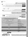 26
26
-
 27
27
-
 28
28


