AKO -15226 Electronic Controller Manual de usuario
- Tipo
- Manual de usuario

1
5231H000 Ed. 09
es en
Cable calefactor paralelo potencia/m constante para protección de
suelos en cámaras frigoríficas
Constant wattage W/m parallel heating cable for “frost heave” pro-
tection in cold room stores
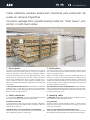
1- Descripción
Los suelos de las cámaras frigoríficas se construyen con una capa de
aislamiento térmico para reducir parte del calor que por conducción
atraviesa el suelo hacia el interior de la cámara, enfriando el subsuelo.
A pesar del aislamiento térmico del suelo, debe compensarse la canti-
dad de calor que lo atraviesa, para evitar que se hiele el subsuelo. Si
este se helara, expandiría hacia arriba con fuerza suficiente para le-
vantar y agrietar el suelo de la cámara frigorífica, pudiendo incluso,
debilitar los cimientos del propio edificio. Este efecto es conocido como
“frost heave”.
El Instituto Internacional del Frío, recomienda varios sistemas de
protección contra el “frost heave”, uno de ellos, es utilizar elementos
calefactores eléctricos colocados debajo del aislamiento térmico, exten-
didos en el suelo en forma de parrilla.
2- Cable calefactor
El cable calefactor AKO-5231, ha sido especialmente diseñado para
este sistema de protección y proporciona ventajas como:
Facilidad de instalación
El cable proporciona unos vatios por metro constantes independien-
temente de su longitud. Ello permite cortarlo a medida en obra en el
momento de su instalación.
Seguridad a bajo coste de instalación y mantenimiento
Todo ello, hace que sea la mejor solución técnica y económica para
evitar el problema expuesto en la descripción.
1- Description
Cold stores are built on a layer of thermal insulation in order to reduce
part of the heat that passes by conduction through the floor into the
room, thus cooling the subsoil.
Despite the thermal insulation of the floor, compensation has to be
made for the amount of heat passing through it in order to prevent
the subsoil from freezing. Were the latter to freeze, it would expand
upwards with sufficient strength to lift and crack the floor of the cold
store, even going as far as to weaken the foundations of the building.
This effect is known as “frost heave”.
The International Institute of Refrigeration recommends several
forms of protection against frost heave, one of which is the use of elec-
tric heating elements placed beneath the thermal insulation and lain on
the floor in the shape of a grille.
2- Heating cable
The AKO-5231 heating cable has been especially designed for this pro-
tection system and offers advantages such as:
Easy installation
The cable ensures a constant wattage per metre, no matter what its
length. This means that the cable can be cut-to-length on site at the
moment of its installation.
Safety at a low installation and maintenance costs
These advantages make this the best and cheapest technical solution
for avoiding the problem explained in the section entitled “Description”.

2
5231H000 Ed. 09
es en
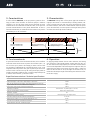
3- Características
El cable calefactor AKO-5231, es de tipo paralelo y potencia de en-
trega por metro lineal constante. Se caracteriza porque el elemento
calefactor, es un hilo de níquel cromo que está enrollado en espiral
alrededor de los dos conductores aislados del cable, con los que hace
contacto alternativamente en unos puntos determinados. El cable va
formando internamente, un sistema de muchas resistencias en paralelo
alimentadas por los dos conductores.
4- Funcionamiento
Al aplicar tensión entre los dos conductores del cable, el hilo calefactor
recibe esta misma tensión entre los puntos de contacto A-B, B-C, C-D,
etc. Ello hace que la potencia de entrega por metro lineal de cable
sea constante e independiente de la longitud del mismo, o sea, a más
longitud de cable mas potencia total, pero la potencia por metro lineal
continua siendo la misma. Este tipo de cable, permite que pueda ser
cortado y terminado a medida en obra, a cualquier longitud múltiple de
la distancia entre contactos, y conectarse a 230 V.
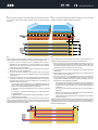
3- Characteristics
The AKO-5231 heating cable is of the parallel type with constant wa-
ttage per linear metre. It is characterised by its heating element, com-
prising a chrome-nickel wire that coils spirally around the two insula-
ted cable conductors, with which it makes alternate contact at specific
points. The cable forms an internal system consisting of several parallel
resistances that are fed by the two conductors.
4- Operation
On applying voltage between the two cable conductors, the heating
wire receives this same voltage between contact points A-B, B-C, CD,
etc. This means that the output power per linear metre of cable remains
constant and independent of the cable length: the longer the cable, the
greater the total power, but the power per linear metre is always the
same. This kind of cable can be cut-to-length and finished on site, no
matter what the multiple length of the heating zone and to be connec-
ted to 230 V supply.
DETALLE CONSTRUCTIVO
DETAIL OF CONSTRUCTION
Coductor de calentamiento
Heating element
Distancia entre contactos
Heating zone length
Conductores
Conductors
230 V
230 V
B
A
A
B
C
C
D
D
Especificaciones técnicas / Technical specifications
Referencia de catálogo / Catalog number AKO-5231
Potencia de entrega (± 7%) a 230 V /
Power output (± 7%) at 230 V
10 W/m
Temp. máx. de exposición (desconectado) /
Max. exposure temperature (power off)
70 ºC
Longitud máxima del circuito (m) /
Maximum circuit length (m)
150 m
Distancia entre contactos (mm) /
Heating zone length (mm)
1000 m
Conductores /
Conductors
Cobre estañado /
Tin-plated copper
(2 x 1.5 mm2)
Conductor de calentamiento /
Heating conductor
Níquel-Cromo /
Nickel-Chrome
Aislamiento /
Insulation
PVC
Rigidez dieléctrica /
Dielectric strength
Tensión de ensayo /
Test voltage
: 1500 V~
Dimensiones exteriores nominales /
Nominal outer dimensions
9 x 6.5 mm
Radio mínimo de curvatura a -15 ºC /
Minimun bend radius at -15 ºC
20 mm
Fuerza de tracción admisible /
Allowable tensile strength
120 N
Longitud bobina de suministro /
Standard reel length
100 m

3
5231H000 Ed. 09
es en
5- Metros de cable a instalar
La potencia necesaria para evitar la congelación del subsuelo de las
cámaras frigoríficas es inferior a 20 W/m2 cuando se instalan los si-
guientes espesores de aislamiento:
Longitud del cable calefactor a instalar:
-2 m de cable AKO-5231 por cada m2 de superficie de suelo
6- Accesorios
Para conseguir una correcta instalación del cable calefactor y un buen
funcionamiento de la instalación, deberán utilizarse los accesorios ade-
cuados, de los que, en sus publicaciones correspondientes, se detallan
todas sus características.
Sonda PTC o Pt100 de longitud a escoger de entre las que se indican:
Las sondas deben instalarse de forma que sean recuperables y también
pueden prolongarse mediante cable apantallado.
Temperatura mínima de la cámara (ºC)
Minimum cool temperature (ºC)
Espesor de aislamiento (mm)
Conductividad térmica / λref. a 10 ºC = 0.034 W/(mK)
Insulation thickness (mm)
Thermal conductivity / λref. at 10 ºC = 0.034 W/(mK)
-10 50
-20 100
-30 150
-40 200
5- Length of cable to be installed
The wattage required in order to avoid frost heave in cold stores is
lower than 20 W/m2 when these insulation thickness are installed:
Heating cable length to install:
-2 m of AKO-5231 cable per m2 of floor surface
6- Accessories
In order to ensure that the heating cable is correctly installed and that
the installation is running properly, the appropriate accessories must
be used. The characteristics of these accessories are described in the
corresponding publications.
Length probe PTC or Pt100 to be selected from the following models:
The probes must be installed in such a way that they can be recovered
and, when required, extended by means of a shielded cable.
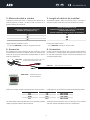
AKO-12193 Kit para extremos de conexión a caja + final
Kit for connection ends to box + end
M25
AKO-5238 Kit de terminación / Termination kit
AKO-15226 Termostato electrónico
Electronic thermostat
Sonda / Probe Longitud / Length Ref.
PTC 2 m AKO-155802
PTC 3 m AKO-155803
Pt100 10 m AKO-15584
PTC 30 m AKO-155830

4
5231H000 Ed. 09
es en
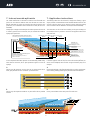
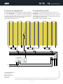
7- Instrucciones de aplicación
Los cables calefactores se instalarán en tramos rectos formando una
parrilla con una distancia máxima entre ellos de 500 mm. Como me-
dida de seguridad, los cables se instalarán bajo tubo de plástico para
protección, con un diámetro interior mínimo de 19 mm (25 mm reco-
mendado).
Siempre que se tenga accesibilidad por dos lados opuestos del suelo de
la cámara y para facilitar la instalación, ésta, se realizará de acuerdo al
ejemplo que exponemos.
Si no se dispone de dos lados opuestos con accesibilidad, pueden adop-
tarse diversas soluciones, de las que exponemos algunas a título de
ejemplo:
A
Instalar cajas de registro en el suelo para unir los tramos rectos de los
tubos, que permitan una fácil instalación y mantenimiento.
7- Application instructions
The heating cables must be installed in straight lines forming a grille
shape, and with a maximum distance of 500 mm between each one. For
security’s sake, the cables will be installed in plastic protection tubing
with a minimum interior diameter of 19 mm (25 mm recommended).
The installation will be carried out according to the given example on
the condition that it is possible to reach the two opposite sides of the
cold store floor.
If the two opposite sides of the floor cannot be reached, different so-
lutions can be adopted; some of which are given below by way of an
example:
A
Install manhole boxes in the floor through which to join the straight stret-
ches of tubing, thereby permitting easy installation and maintenance.
Cable calefactor
Heating cable
Tubo de plástico Ø interior mínimo de 19 mm
Plastic tubing with a minimum interior Ø of 19 mm
Caja de conexión
Junction box
Inclinación para evitar entrada de agua en
instalaciones intemperie
Slope to prevent the entry of water in
outdoor installations
Hormigón / Concrete
Capa aislante
Insulating layer
Base / Hard core
Subsuelo / Subsoil
Enlosado / Tiles
Barrera de vapor /
Steam barrier
Cable calefactor / Heating cable
Distancia máx. entre cables / Max. distance between cables
500 mm 500 mm 500 mm
==
Sensor termostato / Thermostat sensor
500
mm
500
mm
500
mm
500 mm
500 mm
500 mm
B
Install junction boxes to the lower part of the side walls.
B
Instalar cajas de empalme situadas en la parte inferior de las paredes
laterales.

5
5231H000 Ed. 09
es en
C
Instalar cajas de empalme enterradas debajo del aislamiento térmico
y a la misma altura que los tubos, situadas a 500 mm de las paredes
laterales.
D
Instalar doble circuito de cable calefactor (uno de servicio y uno de
reserva) enterrando directamente los cables sin tubo de protección.
• Los dos cables se instalarán juntos , quedando uno en servicio
regulado por los termostatos y el otro de reserva que se dejará
inactivo. Los dos cables se instalarán con todos sus kits y hasta el
interior de las cajas de conexión.
• Los kits de extremo final deben quedar en el exterior y en el mismo
lado que las cajas de alimentación.
• El circuito de reserva quedará sin alimentar hasta una eventual
utilización en caso de que se produjera alguna anomalía debida
a la instalación.
• Instalado el cable con los kits correspondientes y conexionado a
las cajas de alimentación, inmediatamente después de colocado
el mortero de nivelación y antes de cubrirlo con el aislamiento, es
necesario medir y comprobar:
- La resistencia de aislamiento (con un megóhmetro) entre los
cables conductores y tierra para asegurar que el aislamiento del
cable no se ha deteriorado durante la instalación.
- El valor de la resistencia obtenido ha de ser superior a 20 MW
a 1000 Vcc.
- Dar tensión al cable para comprobar que no saltan diferencial
ni magnetotérmico.
- Comprobar que la intensidad del cable corresponde a la canti-
dad de metros instalados.
En el caso de que alguna medición no haya sido correcta, extraer el
cable y revisarlo. Por este motivo es imprescindible que las mediciones
se efectúen inmediatamente, ya que una vez el hormigón esté seco el
cable calefactor ya no es recuperable.
C
Install junction boxes beneath the thermal insulation and at the same
height as the tubes, at 500 mm from the side walls.
D
Install heating cable with a double circuit (one in service and one as a
standby), directly burying the cables without a protection tube.
• The two cables will be installed together. The cable in service will
be controlled by the thermostats and the other standby cable will
be left inactive. Both cables will be installed with all of their kits
and must reach the inside of the junction boxes.
• The end kits must stay on the outside and on the same side as the
input boxes.
• The standby circuit will not be activated unless it is required for use
due to a fault in the installation.
• Once the cable with its corresponding kits has been connected
to the input boxes, and immediately after having lain the leve-
lling mortar, but before covering it with the insulating layer, the
following must be gauged and checked:
- The resistance of the insulation (with the help of a megohmme-
ter) between the conducting cables and the earth in order to
ensure that the cable insulation has not been damaged during
installation.
- The value of the resistance obtained must be over 20 MW at
1000 Vdc.
- Energise the cable to ensure that neither the leakage detection
nor the circuit breaker switches blow.
- Check that the intensity of the cable corresponds to the number
of metres installed.
Should any of the measurements not have past the test correctly, remove
the cable and check it. This is why the measurements must be taken im-
mediately because, once the concrete has dried, it is no longer possible to
remove the heating cable.
500
mm
500
mm
500
mm
500 mm
500 mm500 mm

6
5231H000 Ed. 09
es en
AKO ELECTROMECÁNICA , S.A.L.
Avda. Roquetes, 30-38
08812 • Sant Pere de Ribes.
Barcelona • Spain
www.ako.com
355231000 Rev. 08 2023
Nos reservamos el derecho de suministrar materiales que pudieran diferir levemente de los descritos en nuestras Hojas Técnicas. Información actualizada en nuestra web.
We reserve the right to supply materials that might vary slightly to those described in our Technical Sheets. Updated information is available on our website.
8- Control de temperatura
Es aconsejable la instalación de un termostato por cada 90 m2 de superficie.
Termostato AKO-15226 con una temperatura de ajuste (set point) de
5 ºC, con el sensor de la sonda situada en el punto más desfavorable
y equidistante entre dos cables calefactores, que permitirá controlar y
visualizar la temperatura del suelo y ahorrar energía.
Ejemplo esquema conexión eléctrica:
8- Temperature control
It is advisable to install 1 thermostats for each 90 m2 of floor area.
AKO-15226 thermostat with a temperature Set point of 5 ºC, placing
the probe sensor at the most unfavourable point and at an equal dis-
tance between the two heating cables, in order to see and control the
ground temperature and save energy.
Example of the layout of an electric connection:
AKO-15226
1 2 6 7 8 16 1817
400 V~
230 V~
L1 L2 L3
N
SONDA /
PROBE
AKO-12193
-
 1
1
-
 2
2
-
 3
3
-
 4
4
-
 5
5
-
 6
6


