Generac XG7000E 0057980 Manual de usuario
- Categoría
- Generadores de poder
- Tipo
- Manual de usuario

www.generac.com or 1-888-436-3722
Owner's Manual
XG Series 6,500-8,000 Watt Portable Generator
MODELS: 005796-0 (XG6500), 005797-0 (XG7000),
005798-0 (XG7000E), 005800-0 (XG8000),
005747-0 (XG8000E)

Introduction ............................................................. 1
Read this Manual Thoroughly ................................. 1
Safety Rules ........................................................... 1
Standards Index .............................................................3
General Information ................................................ 4
1.1 Unpacking ......................................................................4
1.1.1 Accessory Box ..................................................4
1.2 Assembly .......................................................................4
1.2.1 Assembling the Wheel Kit and Frame Foot ..........4
Operation ................................................................ 5
2.1 Know the Generator .......................................................5
2.1.1 Battery Connection (XG7000E & XG8000E) .......6
2.2 Hourmeter ......................................................................6
2.3 Cord Sets and Connection Plugs ....................................6
2.3.1 120 VAC, 20 Amp, GFCI Duplex Receptacle .......6
2.3.2 120/240 VAC, 30 Amp Receptacle .....................6
2.4 How to Use the Generator ..............................................7
2.4.1 System Ground ..................................................7
2.4.2 Grounding the Generator ....................................7
2.4.3 Neutral to Frame Grounding ...............................8
2.4.4 Connecting Electrical Loads ...............................8
2.5 Don’t Overload the Generator ..........................................8
2.6 Wattage Reference Guide ...............................................8
2.7 Before Starting the Generator .........................................9
2.7.1 Adding Engine Oil ..............................................9
2.7.2 Adding Gasoline .................................................9
2.8 To Start the Engine .......................................................10
2.8.1 Manual (Recoil) Starting ..................................10
2.8.2 Electric Starting (XG7000E & XG8000E) ..........11
2.9 Stopping the Engine .....................................................11
2.10 Low Oil Pressure Shutdown System .............................11
2.10.1 Restarting ........................................................11
2.11 Charging a Battery .......................................................11
Maintenance ......................................................... 11
3.1 Maintenance Schedule .................................................11
3.2 Product Specifications ..................................................11
3.2.1 Generator Specifications ..................................11
3.2.2 Engine Specifications .......................................12
3.2.3 Emissions Information .....................................12
3.3 General Recommendations ...........................................12
3.3.1 Generator Maintenance ....................................12
3.3.2 To Clean the Generator .....................................13
3.3.3 Engine Maintenance .........................................13
3.3.4 Checking Oil Level ...........................................13
3.3.5 Changing the Oil and Oil Filter ..........................13
3.3.6 Replacing the Spark Plug .................................13
3.4 Service Air Cleaner .......................................................13
3.5 Clean Spark Arrestor Screen.........................................14
3.6 General ........................................................................14
3.7 Long Term Storage .......................................................14
3.8 Other Storage Tips .......................................................15
Battery Service ..................................................... 15
4.1 Battery Replacement (XG7000E & XG8000E) ...............15
Troubleshooting .................................................... 16
5.1 Troubleshooting Guide ..................................................16
Notes .................................................................... 17
Warranty ............................................................... 18
Table of Contents

INTRODUCTION
Thank you for purchasing this model by Generac Power Systems,
Inc. This model is a compact, high performance, air-cooled,
engine driven generator designed to supply electrical power to
operate electrical loads where no utility power is available or in
place of utility due to a power outage.
READ THIS MANUAL THOROUGHLY
If any portion of this manual is not understood, contact the
nearest Authorized Dealer for starting, operating and servicing
procedures.
The operator is responsible for proper and safe use of the
equipment. We strongly recommend that the operator read this
manual and thoroughly understand all instructions before using the
equipment. We also strongly recommend instructing other users to
properly start and operate the unit. This prepares them if they need
to operate the equipment in an emergency.
The generator can operate safely, efficiently and reliably only if it
is properly located, operated and maintained. Before operating or
servicing the generator:
Become familiar with and strictly adhere to all local, state and •
national codes and regulations.
Study all safety warnings in this manual and on the product •
carefully.
Become familiar with this manual and the unit before use.•
The manufacturer cannot anticipate every possible circumstance
that might involve a hazard. The warnings in this manual, and on
tags and decals affixed to the unit are, therefore, not all inclusive.
If using a procedure, work method or operating technique that the
manufacturer does not specifically recommend, ensure that it is
safe for others. Also make sure the procedure, work method or
operating technique utilized does not render the generator unsafe.
THE INFORMATION CONTAINED HEREIN WAS BASED ON
MACHINES IN PRODUCTION AT THE TIME OF PUBLICATION.
GENERAC RESERVES THE RIGHT TO MODIFY THIS MANUAL AT
ANY TIME.
SAFETY RULES
Throughout this publication, and on tags and decals affixed to the
generator, DANGER, WARNING, CAUTION and NOTE blocks are
used to alert personnel to special instructions about a particular
operation that may be hazardous if performed incorrectly or
carelessly. Observe them carefully. Their definitions are as
follows:
INDICATES A HAZARDOUS SITUATION OR ACTION WHICH, IF
NOT AVOIDED, WILL RESULT IN DEATH OR SERIOUS INJURY.
Indicates a hazardous situation or action which, if not
avoided, could result in death or serious injury.
Indicates a hazardous situation or action which, if not
avoided, could result in minor or moderate injury.
NOTE:
Notes contain additional information important to a procedure
and will be found within the regular text body of this manual.
These safety warnings cannot eliminate the hazards that they
indicate. Common sense and strict compliance with the special
instructions while performing the action or service are essential to
preventing accidents.
Four commonly used safety symbols accompany the DANGER,
WARNING and CAUTION blocks. The type of information each
indicates is as follows:
n
This symbol points out important safety
information that, if not followed, could
endanger personal safety and/or property of
others.
This symbol points out potential explosion
hazard.
This symbol points out potential fire hazard.
This symbol points out potential electrical
shock hazard.
GENERAL HAZARDS
Never operate in an enclosed area or indoors. •
For safety reasons, the manufacturer recommends that the •
maintenance of this equipment is carried out by an Authorized
Dealer. Inspect the generator regularly, and contact the nearest
Authorized Dealer for parts needing repair or replacement.
Operate generator only on level surfaces and where it will not be •
exposed to excessive moisture, dirt, dust or corrosive vapors.
Keep hands, feet, clothing, etc., away from drive belts, fans, •
and other moving parts. Never remove any fan guard or shield
while the unit is operating.
Certain parts of the generator get extremely hot during •
operation. Keep clear of the generator until it has cooled to
avoid severe burns.
Do NOT operate generator in the rain.•
Do not alter the construction of the generator or change •
controls which might create an unsafe operating condition.
Never start or stop the unit with electrical loads connected •
to receptacles AND with connected devices turned ON. Start
the engine and let it stabilize before connecting electrical
loads. Disconnect all electrical loads before shutting down the
generator.
Do not insert objects through unit’s cooling slots.•
When working on this equipment, remain alert at all times. •
Never work on the equipment when physically or mentally
fatigued.
1
Introduction

2
Never use the generator or any of its parts as a step. Stepping •
on the unit can stress and break parts, and may result in
dangerous operating conditions from leaking exhaust gases,
fuel leakage, oil leakage, etc.
On electric start models, disconnect the POSITIVE (+) battery •
cable from the engine starter OR the NEGATIVE (-) battery
cable from the battery terminal, whichever is easier, before
transporting the generator.
NOTE:
This generator is equipped with a spark arrestor muffler. The
spark arrestor must be maintained in effective working order
by the owner/ operator. In the State of California, a spark
arrestor is required by law (Section 4442 of the California
Public Resources Code). Other states may have similar laws.
Federal laws apply on federal lands.
EXHAUST & LOCATION HAZARDS
Never operate in an enclosed area or indoors! • NEVER use in
the home, or in partly enclosed areas such as garages, even
if doors and windows are open! ONLY use outdoors and far
from open windows, doors, vents, and in an area that will not
accumulate deadly exhaust.
The engine exhaust fumes contain carbon monoxide, which •
can you cannot see or smell. This poisonous gas, if breathed
in sufficient concentrations, can cause unconsciousness or
even death.
Adequate, unobstructed flow of cooling and ventilating air •
is critical to correct generator operation. Do not alter the
installation or permit even partial blockage of ventilation
provisions, as this can seriously affect safe operation of the
generator. The generator MUST be operated outdoors.
This exhaust system must be properly maintained. Do nothing •
that might render the exhaust system unsafe or in noncompliance
with any local codes and/or standards.
Always use a battery operated carbon monoxide alarm indoors, •
installed according to the manufacturers instructions.
If you start to feel sick, dizzy, or weak after the generator has •
been running, move to fresh air IMMEDIATELY. See a doctor, as
you could have carbon monoxide poisoning.
ELECTRICAL HAZARDS
The • generator produces dangerously high voltage when in
operation. Avoid contact with bare wires, terminals, connections,
etc., while the unit is running, even on equipment connected
to the generator. Ensure all appropriate covers, guards and
barriers are in place before operating the generator.
Never handle any kind of electrical cord or device while •
standing in water, while barefoot or while hands or feet are wet.
DANGEROUS ELECTRICAL SHOCK MAY RESULT.
The National Electric Code (NEC) requires the frame and external •
electrically conductive parts of the generator be properly
connected to an approved earth ground. Local electrical codes
may also require proper grounding of the generator. Consult
with a local electrician for grounding requirements in the area.
Use a ground fault circuit interrupter in any damp or highly •
conductive area (such as metal decking or steel work).
Do not use worn, bare, frayed or otherwise damaged electrical •
cord sets with the generator.
Before performing any maintenance on the generator, disconnect •
the engine starting battery (if equipped) to prevent accidental
start up. Disconnect the cable from the battery post indicated
by a NEGATIVE, NEG or (–) first. Reconnect that cable last.
In case of accident caused by electric shock, immediately shut •
down the source of electrical power. If this is not possible,
attempt to free the victim from the live conductor. AVOID
DIRECT CONTACT WITH THE VICTIM. Use a non-conducting
implement, such as a rope or board, to free the victim from the
live conductor. If the victim is unconscious, apply first aid and
get immediate medical help.
FIRE HAZARDS
Gasoline is highly FLAMMABLE and its vapors are EXPLOSIVE• .
Do not permit smoking, open flames, sparks or heat in the
vicinity while handling gasoline.
Never add fuel while unit is running or hot. Allow engine to cool •
completely before adding fuel.
Never fill fuel tank indoors. • Comply with all laws regulating
storage and handling of gasoline.
Do not overfill the fuel tank. Always allow room for fuel •
expansion. If tank is over-filled, fuel can overflow onto a hot
engine and cause FIRE or an EXPLOSION. Never store generator
with fuel in tank where gasoline vapors might reach an open
flame, spark or pilot light (as on a furnace, water heater or
clothes dryer). FIRE or EXPLOSION may result. Allow unit to
cool entirely before storage.
Wipe up any fuel or oil spills immediately. Ensure that no •
combustible materials are left on or near the generator. Keep the
area surrounding the generator clean and free from debris and
keep a clearance of five (5) feet on all side to allow for proper
ventilation of the generator.
Safety Rules

3
Do not insert objects through unit’s cooling slots.•
Do not • operate the generator if connected electrical devices
overheat, if electrical output is lost, if engine or generator sparks
or if flames or smoke are observed while unit is running.
Keep a fire extinguisher near the generator at all times. •
STANDARDS INDEX
In the absence of pertinent standards, codes, regulations and
laws, the published information listed below may be used as a
guideline for operation of this equipment. Always reference the
latest revision available for the standards listed.
1. NFPA No. 70, NFPA HANDBOOK OF NATIONAL ELECTRIC
CODE.
2. Article X, NATIONAL BUILDING CODE, available from the
American Insurance Association, 85 John Street, New York,
N.Y. 10038.
3. AGRICULTURAL WIRING HANDBOOK, available from the Food
and Energy Council, 909 University Avenue, Columbia, MO
65201.
4. ASAE EP-3634, INSTALLATION AND MAINTENANCE OF
FARM STANDBY ELECTRICAL SYSTEMS, available from the
American Society of Agricultural Engineers, 2950 Niles Road,
St. Joseph, MI 49085.
MODEL NO:
SERIAL NO:
Generator Identification
Unit ID
Locations
CALIFORNIA PROPOSITION 65 WARNING
Engine exhaust and some of its constituents are known
to the State of California to cause cancer, birth defects
and other reproductive harm.
CALIFORNIA PROPOSITION 65 WARNING
This product contains or emits chemicals known to the
State of California to cause cancer, birth defects and
other reproductive harm.
Safety Rules

1.1 UNPACKING
Remove all packaging material.•
Remove separate accessory box.•
Remove carton off the generator.•
1.1.1 ACCESSORY BOX
Check all contents (Figure 1). If any parts are missing or damaged
locate an authorized dealer at 1-888-775-6937.
Contents include:
2 – Axle Pins • Oil Filter•
2 – Wheel Spacers • Air Filter •
2 – Hair Pins • Spark Plug•
2 – Wheels • Spark Plug Wrench•
1 – Frame Foot • Shop Towel•
2 – Frame Bolts • 2 – Frame Washers•
2 – Vibration Mounts • Oil Funnel•
4 – Flange Nuts 12 Volt Adaptor Plug Charger•
2 – 1 Quart SAE 30 Oil Bottles•
Figure 1 – Accessory Boxes
1.2 ASSEMBLY
Read entire Owner's Manual before attempting to assemble or
operate the generator. The generator requires some assembly
prior to using it. If problems arise when assembling the generator,
please call the Generator Helpline at 1-888-775-6937.
1.2.1 ASSEMBLING THE WHEEL KIT AND FRAME FOOT
The wheel kit is designed to greatly improve the portability of the
generator. You will need the following tools to install the wheel
kit: Pliers, 1/2" (13mm) wrench and a socket wrench with a 1/2"
(13mm) socket.
NOTE:
The wheel kit is not intended for over-the-road use.
Refer to Figure 2 and install the wheel kit and frame foot as •
follows:
Slide the Axle Pin through the Wheel, Wheel S• pacer (Washer)
and the Frame.
Install the Hair Pin to the Axle Pin to secure the wheel. Repeat •
for the opposite side.
Secure the Vibration Mounts to the Frame Foot with the included •
locking nuts.
To install the Frame Foot, install the Frame Bolts though the •
Frame Washers, Frame and Frame foot. Secure with the locking
nuts.
Figure 2 – Wheel and Foot Assembly
ASSEMBLE
FRAME
FOOT
SECURE WHEEL
AND AXLE WITH
HAIR PIN
SLIDE AXLE
THROUGH WHEEL
AND WHEEL
SPACER
WHEEL SPACER
(WASHER)
FRAME
BOLT
FRAME
WASHER
FLANGE
NUT
4
General Information

5
2.1 KNOW THE GENERATOR
Read the entire Owner’s Manual and Safety Rules before
operating this generator.
Compare the generator to Figures 3 through 6 to become
familiarized with the locations of various controls and adjustments.
Save this manual for future reference.
1. Choke Knob – Used when starting a cold engine (Pull/Push).
2. Engine Switch – Controls the operation of the generator. On
electric start models the switch is Start/Run/Stop. On recoil
start models the switch is On/Off.
3. Fuel Shut Off – Valve between fuel tank and carburetor. Turn
off and run carburetor out of fuel for extended storage.
4. Panel LED's – Provide illumination of the control panel while
the generator is operating.
5. 120/240 Volt AC, 30 Amp Locking Receptacle – Supplies
electrical power for the operation of 120 and/or 240 Volt AC,
30 Amp, single-phase, 60 Hz, electrical lighting, appliance,
tool and motor loads.
6. 120 Volt AC, 20 Amp, GFCI Duplex Receptacle – Supplies
electrical power for the operation of 120 Volt AC, 20 Amp,
single-phase, 60 Hz electrical lighting, appliance, tool and
motor loads. It also provides protection with an Integral
Ground Fault Circuit Interrupter, complete with a press to
"Test" and "Reset" button.
7. Circuit Breakers (AC) – Each 20 Amp receptacle is provided
with a push-to-reset circuit breaker to protect the generator
against electrical overload.
8. Circuit Breakers (AC) – The 30 Amp receptacle is protected
with a pair of push-to-reset circuit breakers to protect the
generator against electrical overload.
9. PowerBar – Indicates the amount of power being used from
the generator; each section is approximately 25%
10. Hourmeter – Provides operating hours for Service Intervals.
11. Battery Charger Input (Electric Start Models) – This
receptacle allows the capability to recharge the 12 VDC engine
starting battery with the 12 Volt Adaptor Plug Charger. The
battery is protected by a 1.50 Amp in-line fuse which is inside
the control panel.
12. Fuel Tank – Tank holds 9 U.S. gallons of fuel.
13. Fuel Gauge – Shows fuel level in tank.
14. Handles – Pivot and retract for storage. Press the spring-
loaded button to move handles.
15. Oil Fill – Check oil level and add oil here.
16. Grounding Lug – Ground the generator to an approved earth
ground here. See "Grounding the Generator" for details.
17. Muffler – Includes the spark arrestor and quiets the engine.
18. Spark Plug Location – The spark plug ignites the Air/Fuel
Mixture (Side panel must be removed).
19. Engine Oil Filter – Filters engine oil; see Section 3.1 for the
proper service intervals.
20. Air Cleaner – Filters intake air as it is drawn into the engine.
21. Oil Drain – Drain valve to remove used oil from the engine
crankcase.
22. Recoil Starter – Use to start engine manually.
Figure 3 – Generator Locations
Operation

6
2.1.1 BATTERY CONNECTION (XG7000E & XG8000E)
NOTE:
The battery shipped with the generator has been fully charged.
A battery may lose some of its charge when not in use for
prolonged periods of time. If the battery is unable to crank
the engine, plug in the 12V charger included in the accessory
box (see the Charging the Battery section). RUNNING THE
GENERATOR DOES NOT CHARGE THE BATTERY.
The positive battery wire was deliberately left detached for
shipping. To operate the unit, attach this wire to the terminal on
the starter motor as shown. Do not overtighten. Slide the attached
rubber boot over the starter terminal. See Figure 4.
Figure 4 – Battery Connection
ENGINE
STARTER
POSITIVE (+)
BATTERY CABLE
2.2 HOURMETER
The Hourmeter tracks hours of operation for scheduled
maintenance:
There will be a one time break in "CHG OIL" message that flashes
with the elapsed time in hours and tenths after the first 30 hours
of operation.
This message will actually begin flashing at 29 hours and disable
itself at 31 hours providing a two hour window to perform the
service.
There will be a subsequent "CHG OIL" message every 100 hours.
The message will flash one hour before and one hour after each
100 hour interval, again providing a two hour window to perform
service.
Every 200 hours the "SVC" icon on the lower left hand corner of
the display will flash. The message will flash one hour before and
one hour after each 200 hour interval providing a two hour window
to perform service.
When the hour meter is in the Flash Alert mode, the maintenance
message will always alternate with elapsed time in hours and
tenths. The hours will flash four times, then alternate with the
maintenance message four times until the meter resets itself.
100 hours - CHG OIL — Oil Change Interval (Every 100 hrs)•
200 hours - SVC — Air Filter Interval (Every 200 hrs)•
2.3 CORD SETS AND CONNECTION PLUGS
2.3.1 120 VAC, 20 AMP, GFCI DUPLEX RECEPTACLE
This is a 120 Volt outlet protected against overload by a 20 Amp
push-to-reset circuit breaker (Figure 5). Use each socket to power
120 Volt AC, single phase, 60 Hz electrical loads requiring up to a
combined 2400 watts (2.4 kW) or 20 Amps of current. Use only
high quality, well-insulated, 3-wire grounded cord sets rated for
125 Volts at 20 Amps (or greater).
Keep extension cords as short as possible, preferably less than
15 feet long, to prevent voltage drop and possible overheating of
wires.
2.3.2 120/240 VAC, 30 AMP RECEPTACLE
Use a NEMA L14-30 plug with this receptacle (rotate to lock/
unlock). Connect a suitable 4-wire grounded cord set to the plug
and to the desired load. The cord set should be rated for 250 Volts
AC at 30 Amps (or greater) (Figure 5).
Use this receptacle to operate 120 Volt AC, 60 Hz, single phase
loads requiring up to 3600 watts (3.6 kW) of power at 30 Amps
or 240 Volt AC, 60 Hz, single phase loads requiring 6,500 to 8000
watts of power, depending on the model. The outlet is protected by
a 30 Amp circuit breaker.
Figure 5 – Generator Receptacles
120 VAC 20A
GFCI RECEPTACLE
120/240 VAC 30A
RECEPTACLE
Operation

2.4 HOW TO USE THE GENERATOR
If there are any problems operating the generator, please call the
generator helpline at 1-888-436-3722.
n
Never operate in an enclosed area or indoors!
NEVER use in the home, or in partly enclosed
areas such as garages, even if doors and
windows are open! ONLY use outdoors and far
from open windows, doors, vents, and in an
area that will not accumulate deadly exhaust.
n
The engine exhaust fumes contain carbon
monoxide, which can you cannot see or smell.
This poisonous gas, if breathed in sufficient
concentrations, can cause unconsciousness or
even death.
n
Adequate, unobstructed flow of cooling and
ventilating air is critical to correct generator
operation. Do not alter the installation or permit
even partial blockage of ventilation provisions,
as this can seriously affect safe operation
of the generator. The generator MUST be
operated outdoors.
n
This exhaust system must be properly
maintained. Do nothing that might render the
exhaust system unsafe or in noncompliance
with any local codes and/or standards.
n
The manufacturer recommends installing
a battery operated carbon monoxide alarm
indoors, according to the manufacturers
instructions.
2.4.1 SYSTEM GROUND
The generator has a system ground that connects the generator
frame components to the ground terminals on the AC output
receptacles. The system ground is bonded to the AC neutral wire
in the generator control panel via a jumper wire.
Special Requirements
There may be Federal or State Occupational Safety and Health
Administration (OSHA) regulations, local codes, or ordinances that
apply to the intended use of the generator.
Please consult a qualified electrician, electrical inspector, or the
local agency having jurisdiction:
In some areas, generators are required to be registered with •
local utility companies.
If the generator is used at a construction site, there may be •
additional regulations which must be observed.
Connecting to a Building’s Electrical System
Connections for standby power to a building’s electrical system
must be made by a qualified electrician. The connection must
isolate the generator power from utility power or other alternative
power sources and must comply with all applicable laws and
electrical codes.
2.4.2 GROUNDING THE GENERATOR
n
The National Electrical Code requires that the
frame and external electrically conductive parts
of this generator be properly connected to an
approved earth ground.
Local electrical codes may also require proper grounding of
the unit (Figure 6). For that purpose, connecting a No. 10 AWG
(American Wire Gauge) stranded copper wire to the grounding lug
and to an earth-driven copper or brass grounding rod (electrode)
provides adequate protection against electrical shock. However,
local codes may vary widely. Consult with a local electrician for
grounding requirements in the area.
Proper grounding of the generator will help prevent electrical
shock in the event of a ground fault condition in the generator or in
connected electrical devices. Proper grounding also helps dissipate
static electricity, which often builds up in ungrounded devices.
Figure 6 – Generator Ground Location
XG6500 & XG7000
GROUND LOCATION
XG8000
GROUND
LOCATION
7
Operation

2.4.3 NEUTRAL TO FRAME GROUNDING
If service work is performed on the alternator, DO NOT discard
the white jumper wires from the terminal block to the alternator
ground, located on the rear bearing carrier. Always make sure
the wires are properly connected before using the generator after
alternator service work is done (Figure 7).
Failure to reconnect these wires may create a
potential shock hazard when the generator is
running!
Figure 7 – Neutral to Frame Ground
NEUTRAL TO FRAME GROUND XG6500
DO NOT DISCARD
THESE WIRES!
NEUTRAL TO FRAME GROUND
XG7000 & 8000
DO NOT DISCARD
THESE WIRES!
2.4.3 CONNECTING ELECTRICAL LOADS
DO NOT connect 240 Volt loads to 120 Volt receptacles.
DO NOT connect 3 phase loads to the generator.
DO NOT connect 50 Hz loads to the generator.
Let engine stabilize and warm up for a few minutes after •
starting.
Plug in and turn on the desired 120 or 240 Volt AC, single •
phase, 60 Hz electrical loads.
Add up the rated watts (or amps) of all loads to be connected •
at one time. This total should no be greater than (a) the rated
wattage/amperage capacity of the generator or (b) circuit
breaker rating of the receptacle supplying the power. See “Don’t
Overload the Generator
2.5 DON’T OVERLOAD THE GENERATOR
Overloading a generator in excess of its rated wattage capacity
can result in damage to the generator and to connected electrical
devices. Observe the following to prevent overloading the unit:
Add up the total wattage of all electrical devices to be connected •
at one time. This total should NOT be greater than the
generator's wattage capacity.
The rated wattage of lights can be taken from light bulbs. The •
rated wattage of tools, appliances and motors can usually be
found on a data label or decal affixed to the device.
If the appliance, tool or motor does not give wattage, multiply •
volts times ampere rating to determine watts (volts x amps =
watts).
Some electric motors, such as induction types, require about •
three times more watts of power for starting than for running.
This surge of power lasts only a few seconds when starting
such motors. Make sure to allow for high starting wattage when
selecting electrical devices to connect to the generator:
1. Figure the watts needed to start the largest motor.
2. Add to that figure the running watts of all other connected
loads.
The Wattage Reference Guide is provided to assist in determining
how many items the generator can operate at one time.
NOTE:
All figures are approximate. See data label on appliance for
wattage requirements.
2.6 WATTAGE REFERENCE GUIDE
Device . . . . . . . . . . . . . . . . . . . . . . . . . . . . . . . . . . . Running Watts
*Air Conditioner (12,000 Btu) . . . . . . . . . . . . . . . . . . . . . . . . . . 1700
*Air Conditioner (24,000 Btu) . . . . . . . . . . . . . . . . . . . . . . . . . . 3800
*Air Conditioner (40,000 Btu) . . . . . . . . . . . . . . . . . . . . . . . . . . 6000
Battery Charger (20 Amp). . . . . . . . . . . . . . . . . . . . . . . . . . . . . . 500
Belt Sander (3") . . . . . . . . . . . . . . . . . . . . . . . . . . . . . . . . . . . . 1000
Chain Saw . . . . . . . . . . . . . . . . . . . . . . . . . . . . . . . . . . . . . . . . 1200
Circular Saw (6-1/2") . . . . . . . . . . . . . . . . . . . . . . . . . . .800 to 1000
*Clothes Dryer (Electric) . . . . . . . . . . . . . . . . . . . . . . . . . . . . . 5750
*Clothes Dryer (Gas) . . . . . . . . . . . . . . . . . . . . . . . . . . . . . . . . . 700
*Clothes Washer . . . . . . . . . . . . . . . . . . . . . . . . . . . . . . . . . . . 1150
Coffee Maker . . . . . . . . . . . . . . . . . . . . . . . . . . . . . . . . . . . . . . 1750
*Compressor (1 HP). . . . . . . . . . . . . . . . . . . . . . . . . . . . . . . . . 2000
*Compressor (3/4 HP) . . . . . . . . . . . . . . . . . . . . . . . . . . . . . . . 1800
*Compressor (1/2 HP) . . . . . . . . . . . . . . . . . . . . . . . . . . . . . . . 1400
Curling Iron. . . . . . . . . . . . . . . . . . . . . . . . . . . . . . . . . . . . . . . . . 700
*Dehumidifier . . . . . . . . . . . . . . . . . . . . . . . . . . . . . . . . . . . . . . . 650
Disc Sander (9"). . . . . . . . . . . . . . . . . . . . . . . . . . . . . . . . . . . . 1200
Edge Trimmer . . . . . . . . . . . . . . . . . . . . . . . . . . . . . . . . . . . . . . . 500
Electric Blanket . . . . . . . . . . . . . . . . . . . . . . . . . . . . . . . . . . . . . . 400
8
Operation

Electric Nail Gun . . . . . . . . . . . . . . . . . . . . . . . . . . . . . . . . . . . . 1200
Electric Range (per element). . . . . . . . . . . . . . . . . . . . . . . . . . . 1500
Electric Skillet . . . . . . . . . . . . . . . . . . . . . . . . . . . . . . . . . . . . . . 1250
*Freezer . . . . . . .. . . . . . . . . . . . . . . . . . . . . . . . . . . . . . . . . . . ..700
*Furnace Fan (3/5 HP) . . . . . . . . . . . . . . . . . . . . . . . . . . . . . . . . 875
*Garage Door Opener . . . . . . . . . . . . . . . . . . . . . . . . . . . .500 to 750
Hair Dryer. . . . . . . . . . . . . . . . . . . . . . . . . . . . . . . . . . . . . . . . . 1200
Hand Drill . . . . . . . . . . . . . . . . . . . . . . . . . . . . . . . . . . . .250 to 1100
Hedge Trimmer . . . . . . . . . . . . . . . . . . . . . . . . . . . . . . . . . . . . . . 450
Impact Wrench . . . . . . . . . . . . . . . . . . . . . . . . . . . . . . . . . . . . . . 500
Iron. . . . . . . . . . . . . . . . . . . . . . . . . . . . . . . . . . . . . . . . . . . . . . 1200
*Jet Pump . . . . . . . . . . . . . . . . . . . . . . . . . . . . . . . . . . . . . . . . . 800
Lawn Mower. . . . . . . . . . . . . . . . . . . . . . . . . . . . . . . . . . . . . . . 1200
Light Bulb . . . . . . . . . . . . . . . . . . . . . . . . . . . . . . . . . . . . . . . . . . 100
Microwave Oven. . . . . . . . . . . . . . . . . . . . . . . . . . . . . . .700 to 1000
*Milk Cooler . . . . . . . . . . . . . . . . . . . . . . . . . . . . . . . . . . . . . . . 1100
Oil Burner on Furnace . . . . . . . . . . . . . . . . . . . . . . . . . . . . . . . . . 300
Oil Fired Space Heater (140,000 Btu) . . . . . . . . . . . . . . . . . . . . . 400
Oil Fired Space Heater (85,000 Btu) . . . . . . . . . . . . . . . . . . . . . . 225
Oil Fired Space Heater (30,000 Btu) . . . . . . . . . . . . . . . . . . . . . . 150
*Paint Sprayer, Airless (1/3 HP) . . . . . . . . . . . . . . . . . . . . . . . . . 600
Paint Sprayer, Airless (handheld). . . . . . . . . . . . . . . . . . . . . . . . . 150
Radio . . . . . . . . . . . . . . . . . . . . . . . . . . . . . . . . . . . . . . . . .50 to 200
*Refrigerator. . . . . . . . . . . . . . . . . . . . . . . . . . . . . . . . . . . . . . . . 700
Slow Cooker. . . . . . . . . . . . . . . . . . . . . . . . . . . . . . . . . . . . . . . . 200
*Submersible Pump (1-1/2 HP) . . . . . . . . . . . . . . . . . . . . . . . . 2800
*Submersible Pump (1 HP) . . . . . . . . . . . . . . . . . . . . . . . . . . . 2000
*Submersible Pump (1/2 HP) . . . . . . . . . . . . . . . . . . . . . . . . . . 1500
*Sump Pump . . . . . . . . . . . . . . . . . . . . . . . . . . . . . . . . .800 to 1050
*Table Saw (10") . . . . . . . . . . . . . . . . . . . . . . . . . . . . .1750 to 2000
Television . . . . . . . . . . . . . . . . . . . . . . . . . . . . . . . . . . . . .200 to 500
Toaster . . . . . . . . . . . . . . . . . . . . . . . . . . . . . . . . . . . . .1000 to 1650
Weed Trimmer . . . . . . . . . . . . . . . . . . . . . . . . . . . . . . . . . . . . . . 500
* Allow 3 times the listed watts for starting these devices.
2.7 BEFORE STARTING THE GENERATOR
Prior to operating the generator, engine oil and gasoline will need
to be added, as follows:
2.7.1 ADDING ENGINE OIL
All oil should meet minimum American Petroleum Institute (API)
Service Class SJ, SL or better. Use no special additives. Select
the oil's viscosity grade according to the expected operating
temperature (also see chart).
Above 40° F, use SAE 30•
Below 40° F and down to 10° F, use 10W-30•
Below 10° F, use synthetic 5W-30•
n
Any attempt to crank or start the engine before it has
been properly serviced with the recommended oil may
result in an engine failure.
TEMPERATURE IN DEGREES FAHRENHEIT ( F)
TEMPERATURE IN DEGREES CELSIUS ( C)
Place generator on a level surface.•
Clean area around oil fill and remove oil fill cap.•
Slowly fill engine with oil through the oil fill opening until it •
reaches the full mark. Stop filling occasionally to check oil level.
(Engine oil is full when level is up to the threads of the oil fill
plug, see Figure 8)
Install oil fill cap and finger tighten securely.•
Check engine oil level before starting each time thereafter.•
Figure 8 – Oil Level
2.7.2 ADDING GASOLINE
DO NOT light a cigarette or smoke when filling the fuel
tank.
n
Never fill fuel tank indoors. Never fill fuel tank when
engine is running or hot. Avoid spilling gasoline on a hot
engine. Allow engine to cool entirely before filling fuel
tank.
9
Operation

Do not overfill the fuel tank. Always leave room for fuel
expansion. If the fuel tank is overfilled, fuel can overflow
onto a hot engine and cause FIRE or EXPLOSION. Wipe
up any spilled fuel immediately.
Use regular UNLEADED gasoline with the generator engine. Do •
not use premium gasoline. Do not mix oil with gasoline.
Do not use gasoline with more than 10% alcohol such as E85 •
or Methanol.
Clean area around fuel fill cap, remove cap.•
Slowly add unleaded regular gasoline to fuel tank. Fill to bottom •
of screen filter. Be careful not to overfill (Figure 9).
Install fuel cap and wipe up any spilled gasoline. •
Figure 9 – Fuel Fill Level
DO NOT FILL
ABOVE LIP!
IMPORTANT: It is important to prevent gum deposits from forming
in fuel system parts such as the carburetor, fuel hose or tank
during storage. Alcohol-blended fuels (called gasohol, ethanol
or methanol) can attract moisture, which leads to separation and
formation of acids during storage. Acidic gas can damage the fuel
system of an engine while in storage. To avoid engine problems,
the fuel system should be emptied before storage of 30 days or
longer. See the "Storage" section. Never use engine or carburetor
cleaner products in the fuel tank as permanent damage may
occur.
2.8 TO START THE ENGINE
Never start or stop engine with electrical devices plugged into
the receptacles AND devices turned on.
Unplug all electrical loads from the unit's receptacles before •
starting the engine.
Make sure the unit is in a level position.•
Open the fuel shut-off valve (Figure 10).•
Pull engine CHOKE knob outward to • “Full Choke” position
(Figure 11).
Figure 10 – Fuel Shut-off Valve
Figure 11 – Choke Operation
2.8.1 MANUAL (RECOIL) STARTING
To start the generator, put the on/off switch in the ON position.•
Firmly grasp the recoil handle and pull slowly until increased •
resistance is felt. Pull rapidly up and away to start engine.
When the engine starts, push choke knob to “1/2 Choke” •
position until the engine runs smoothly and then fully in to the
“Run” position. If engine falters, pull choke knob back out to
“1/2 Choke” position until the engine runs smoothly and then
to “Run” position.
NOTE:
If engine fires, but does not continue to run, pull choke knob
to “Full Choke” and repeat starting instructions.
IMPORTANT: Do not overload the generator. Also, do not overload
individual panel receptacles. These outlets are protected against
overload with push-to-reset-type circuit breakers. Read “Don’t
Overload the Generator” carefully.
10
Operation

2.8.1 ELECTRIC STARTING (XG7000E & XG8000E)
To start the engine, press and hold the Start/Run/Stop switch in •
the “Start” position. The engine will crank and attempt to start.
When the engine starts, release the switch to the run position.
When the engine starts, push choke knob to “1/2 Choke” •
position until the engine runs smoothly and then fully in to the
“Run” position. If engine falters, pull choke knob back out to
“1/2 Choke” position until the engine runs smoothly and then
to “Run” position.
This generator is also equipped with a manual recoil starter •
which may be used if the battery is discharged.
NOTE:
The engine Start/Run/Stop switch must be in the RUN
position when using the manual recoil starter.
2.9 STOPPING THE ENGINE
Shut off all loads, then unplug the electrical loads from generator •
panel receptacles. Never start or stop the engine with electrical
devices plugged in and turned on.
Let engine run at no-load for several minutes to stabilize the •
internal temperatures of engine and generator.
Move Start/Run/Stop or On/Off switch to the “Off” position.•
Close fuel valve.•
2.10 LOW OIL PRESSURE SHUTDOWN SYSTEM
The engine is equipped with a low oil pressure sensor that shuts
down the engine automatically when the oil pressure drops below
5 psi. A delay built into the low oil shutdown system allows oil
pressure to build during starting. The delay allows the engine to
run for about 10 seconds before sensing oil pressure. If the engine
shuts down by itself and the fuel tank has enough gasoline, check
engine oil level.
2.10.1 RESTARTING
If trying to restart the engine within 10 seconds after it shuts down,
the engine may NOT start. The system needs 5 to 10 seconds to
reset.
If the engine is restarted after such a shutdown and the low oil
pressure has not been corrected, the engine will run for about 10
seconds as described above and then stop.
2.11 CHARGING THE BATTERY (XG7000E & XG8000E)
n
Do not permit smoking, open flame, sparks
or any other source of heat around a battery.
Wear protective goggles, rubber apron and
rubber gloves when working around a battery.
Battery electrolyte fluid is an extremely
corrosive sulfuric acid solution that can cause
severe burns. If spill occurs flush area with
clear water immediately.
Storage batteries give off explosive hydrogen
gas while recharging. An explosive mixture will
remain around the battery for a long time after
it has been charged. The slightest spark can
ignite the hydrogen and cause an explosion.
Such an explosion can shatter the battery and
cause blindness or other serious injury.
Use battery charger plug to keep the battery charged and ready
for use. Battery charging should be done in a dry location.
1. Plug charger into “Battery Charger Input” jack, located on the
control panel. Plug wall receptacle end of the battery charger
into a 120 Volt AC wall outlet.
2. Unplug battery charger from wall outlet and control panel jack
when generator is going to be in use.
NOTE:
Do not use the battery charger for more than 48 hours at one
charge.
3.1 MAINTENANCE SCHEDULE
Follow the calendar intervals. More frequent service is required
when operating in adverse conditions noted below.
Check Oil Level At Each Use
Change Oil and Oil Filter‡ *Every Season/Every 100 Hours
Clean Spark Arrestor Screen *Every Season/Every 100 Hours
Service Air Cleaner **Every Season/Every 200 Hours
Replace Spark Plug Every Season
‡ Change oil after first 30 hours of operation then every season.
* Change oil and oil filter every month when operating under heavy load or in
high temperatures.
** Clean more often under dirty or dusty operating conditions. Replace air
cleaner parts if very dirty.
3.2 PRODUCT SPECIFICATIONS
3.2.1 GENERATOR SPECIFICATIONS
Model # ...............................................................005800-0, 005747-0
Rated Max. Power ...................................................................8.0 kW**
Surge Power ................................................................................10 kW
Rated AC Voltage ......................................................................120/240
Rated Max AC Load
Current @ 240V .............................................................33.3 Amps**
Current @ 120V .............................................................66.7 Amps**
Rated Frequency .................................................... 60 Hz @ 3600 RPM
Phase ................................................................................Single Phase
Rated DC Voltage ...................................................................... 12 Volts
Battery Type .................................................................... 10 AH, 12VDC
11
Maintenance

Model # ...............................................................005797-0, 005798-0
Rated Max. Power ...................................................................7.0 kW**
Surge Power .............................................................................8.75 kW
Rated AC Voltage ......................................................................120/240
Rated Max AC Load
Current @ 240V .............................................................29.2 Amps**
Current @ 120V .............................................................58.3 Amps**
Rated Frequency .................................................... 60 Hz @ 3600 RPM
Phase ................................................................................Single Phase
Rated DC Voltage ...................................................................... 12 Volts
Battery Type .................................................................... 10 AH, 12VDC
Model # ................................................................................ 005796-0
Rated Max. Power ...................................................................6.5 kW**
Surge Power .............................................................................8.13 kW
Rated AC Voltage ......................................................................120/240
Rated Max AC Load
Current @ 240V .............................................................27.1 Amps**
Current @ 120V .............................................................54.2 Amps**
Rated Frequency .................................................... 60 Hz @ 3600 RPM
Phase ................................................................................Single Phase
Rated DC Voltage ...................................................................... 12 Volts
** Maximum wattage and current are subject to, and limited by, such factors
as fuel Btu content, ambient temperature, altitude, engine condition, etc..
Maximum power decreases about 3.5% for each 1,000 feet above sea level;
and will also decrease about 1% for each 6° C (10° F) above 16° C (60° F)
ambient temperature.
3.2.2 ENGINE SPECIFICATIONS
Rated Horsepower @ 3600 RPM ....................................................14.5
Displacement ...............................................................................410cc
Spark Plug Type ...................................Champion RC14YC or Equivalent
Spark Plug Gap ............................................... 0.030 inch or (0.76 mm)
Gasoline Capacity ............................................................ 9 U.S. gallons
Oil Type....................................See Chart in "Adding Engine Oil" Section
Oil Capacity ................................................ w/ Filter Change = 1.5 Qts.
w/o Filter Change = 1.2 Qts.
Run Time/Fuel Consumption-1/2 Load .. 10 Hours / .73 gallons per hour
Class II Emission Certified
3.2.3 EMISSIONS INFORMATION
The Environmental Protection Agency (EPA) and California Air
Resource Board (CARB) require that your generator comply with
exhaust and evaporative emission standards. This generator is
certified to meet the applicable EPA and CARB emission levels.
Additional information regarding the requirements set by EPA and
CARB is as follows:
It is important that you follow the maintenance specifications
provided in this manual to ensure that your engine complies with
the applicable emission standards for the duration of the engine’s
life. This engine is certified to operate on gasoline. The emission
control system on your generator consists of the following:
Fuel System • Air Induction System•
Fuel Tank ~ Intake pipe/manifold
Fuel Cap ~ Air cleaner
Carburetor •
Ignition System
Fuel Lines ~ Spark plug
Evaporative Control System ~ Ignition module•
Carbon Canister • Exhaust System
Vapor Hoses ~ Pulse Air Injection Valve
~ Muffler
The Emissions Compliance Period referred to on the Emissions
Compliance Label indicates the number of operating hours for
which the engine has been shown to meet Federal and California
emission requirements. See the table below to determine the
compliance period for your generator. The displacement of your
generator is listed on the Emissions Compliance Label.
Displacement Category Compliance Period
≥ 66 cc - < 225 cc
A 500 Hours
B 250 Hours
C 125 Hours
≥ 225 cc
A 1000 Hours
B 500 Hours
C 250 Hours
3.3 GENERAL RECOMMENDATIONS
The warranty of the generator does not cover items that have been
subjected to operator abuse or negligence. To receive full value
from the warranty, the operator must maintain the generator as
instructed in this manual.
Some adjustments will need to be made periodically to properly
maintain the generator.
All adjustments in the Maintenance section of this manual should
be made at least once each season. Follow the requirements in the
"Maintenance Schedule".
NOTE:
Once a year replace the spark plug and replace the air filter.
A new spark plug and clean air filter assure proper fuel-air
mixture and help the engine run better and last longer.
3.3.1 GENERATOR MAINTENANCE
Generator maintenance consists of keeping the unit clean and dry.
Operate and store the unit in a clean dry environment where it will
not be exposed to excessive dust, dirt, moisture or any corrosive
vapors. Cooling air slots in the generator must not become clogged
with snow, leaves, or any other foreign material.
Check the cleanliness of the generator frequently and clean when
dust, dirt, oil, moisture or other foreign substances are visible on
its exterior surface.
n
Never insert any object or tool through the air cooling
slots, even if the engine is not running.
12
Maintenance

13
NOTE:
DO NOT use a garden hose to clean generator. Water can
enter the engine fuel system and cause problems. In addition,
if water enters the generator through cooling air slots, some
water will be retained in voids and crevices of the rotor
and stator winding insulation. Water and dirt buildup on the
generator internal windings will eventually decrease the
insulation resistance of these windings.
3.3.2 TO CLEAN THE GENERATOR
Use a damp cloth to wipe exterior surfaces clean.•
A soft, bristle brush may be used to loosen caked on dirt, oil, •
etc.
A vacuum cleaner may be used to pick up loose dirt and •
debris.
Low pressure air (not to exceed 25 psi) may be used to blow •
away dirt. Inspect cooling air slots and openings on the generator.
These openings must be kept clean and unobstructed.
3.3.3 ENGINE MAINTENANCE
n
When working on the generator, always disconnect
negative cable from battery. Also disconnect spark plug
wire from spark plug and keep wire away from spark
plug.
3.3.4 CHECKING OIL LEVEL
See the “BEFORE STARTING THE GENERATOR” section for
information on checking the oil level. The oil level should be
checked before each use, or at least every eight hours of operation.
Keep the oil level maintained.
3.3.5 CHANGING THE OIL AND OIL FILTER
Change the oil and filter after the first 30 hours of operation. Change
the oil every 100 hours or every season thereafter. If running this
unit under dirty or dusty conditions, or in extremely hot weather,
change the oil more often.
n
Hot oil may cause burns. Allow engine to cool before
draining oil. Avoid prolonged or repeated skin exposure
with used oil. Thoroughly wash exposed areas with soap.
Use the following instructions to change the oil:
Clean area around oil drain cap.•
Remove oil drain cap from the drain hose and oil fill plug to drain •
oil completely into a suitable container.
When oil has completely drained, install oil drain cap and tighten •
securely.
Place a suitable container beneath the oil filter and turn •
filter counterclockwise to remove. Discard according to local
regulations.
Coat gasket of new filter with clean engine oil. Turn filter •
clockwise until gasket contacts lightly with filter adapter. Then
tighten an additional 3/4 turn.
Fill oil sump with recommended oil and replace the oil fill plug. (See •
“Before Starting the Generator” for oil recommendations).
Wipe up any spilled oil.•
Dispose of used oil at a proper collection center.•
3.3.6 REPLACING THE SPARK PLUG
Use Champion RC14YC spark plug or equivalent. Replace the
plug once each year. This will help the engine start easier and
run better.
1. Stop the engine and pull the spark plug wire off of the spark
plug.
2. To gain access, remove the four (4) socket head screws and
take off the side panel.
3. Clean the area around the spark plug and remove it from the
cylinder head.
4. Set the spark plug's gap to .76 mm (0.030 in.). Install the
correctly gapped spark plug into the cylinder head (Figure
12).
5. Push the boot firmly on the spark plug and install side panel.
Figure 12 – Spark Plug Gap
3.4 SERVICE AIR CLEANER
The engine will not run properly and may be damaged if using a
dirty air cleaner. Clean or replace the air cleaner paper filter every
200 hours or once a year (Figure 15). Clean or replace more often
if operating under dusty conditions. To clean or replace paper air
filter:
Remove air cleaner cover and remove paper filter (Figure 13).•
Clean paper filter by tapping it gently on a solid surface. If the •
filter is too dirty, replace it with a new one. Dispose of the old
filter properly.
Clean air cleaner cover. Next insert new paper filter into the base •
of the air cleaner. Re-install air cleaner cover.
NOTE:
To order a new air filter, please contact the nearest authorized
service center at 1-888-GENERAC.
Maintenance

14
Figure 13 – Air Filter
AIR FILTER
COVER
3.5 CLEAN SPARK ARRESTOR SCREEN
The engine exhaust muffler has a spark arrestor screen. Inspect
and clean the screen at least once each year (Figure 14). If unit is
used regularly, inspect and clean more often.
If using the generator on any forest-covered,
brush-covered or grass-covered unimproved
land, it must equipped with a spark arrestor.
The spark arrestor must be maintained in good
condition by the owner/operator.
Clean and inspect the spark arrestor when the engine is at ambient
temperature as follows:
Loosen the clamp and remove the spark arrestor screen from •
the muffler.
Inspect screen and replace if torn, perforated or otherwise •
damaged. DO NOT USE a defective screen. If screen is not
damaged, clean it with commercial solvent.
Replace the spark arrestor and secure with the clamp.•
Figure 14 – Spark Arrestor Screen
ARRESTOR
SCREEN
CLAMP
SPARK
ARRESTOR
SCREEN
3.6 GENERAL
The generator should be started at least once every seven days
and be allowed to run at least 30 minutes. If this cannot be done
and the unit must be stored for more than 30 days, use the
following information as a guide to prepare it for storage.
NEVER store engine with fuel in tank indoors
or in enclosed, poorly ventilated areas where
fumes may reach an open flame, spark or pilot
light as on a furnace, water heater, clothes
dryer or other gas appliance.
n
Allow unit to cool entirely before storage.
3.7 LONG TERM STORAGE
It is important to prevent gum deposits from forming in essential
fuel system parts such as the carburetor, fuel hose or tank during
storage. To avoid engine problems, the fuel system should be
emptied before storage of 30 days or longer, as follows:
Remove all gasoline from the fuel tank.•
n
Drain fuel into approved container outdoors, away from
open flame. Be sure engine is cool. Do not smoke in the
vicinity or light a cigarette.
Start and run engine until engine stops from lack of fuel.•
Allow the engine to cool, then drain oil from crankcase. Refill •
with recommended grade.
Remove spark plug and pour about 1/2 ounce (15 ml) of engine •
oil into the cylinder. Cover spark plug hole with rag. Pull the
recoil starter a couple times to lubricate the piston rings and
cylinder bore.
n
Avoid spray from spark plug hole when
cranking engine.
Install and tighten spark plug. Do not connect the spark plug •
wire.
Clean the generator outer surfaces. Check that cooling air slots •
and openings on generator are open and unobstructed.
Store the unit in a clean, dry place.•
Maintenance

3.8 OTHER STORAGE TIPS
Do not store gasoline from one season to another.•
Replace any gasoline can that starts to rust. Rust and/or dirt in •
the gasoline will cause problems with the carburetor and fuel
system.
If possible, store the unit indoors and cover it to give protection •
from dust and dirt. Cover the unit with a suitable protective
cover that does not retain moisture.
BE SURE TO EMPTY THE FUEL TANK. • If it is not practical
to empty the fuel tank and the unit is to be stored for some
time, use a commercially available fuel stabilizer added to the
gasoline to increase the life of the gasoline.
n
NEVER cover the generator while engine and
exhaust area are warm.
4.1 BATTERY REPLACEMENT (XG7000E & XG8000E)
NOTE:
The battery shipped with the generator has been fully charged.
A battery may lose some of its charge when not in use for
prolonged periods of time. If the battery is unable to crank
the engine, plug in the 12V charger included in the accessory
box (see the Charging a Battery section). RUNNING THE
GENERATOR DOES NOT CHARGE THE BATTERY.
The battery shipped with the generator has been provided fully
charged. To replace the battery (See Figure 16):
Remove the side panel as shown. Remove the four bolts •
securing the fuel tank.
Turn the fuel valve on the control panel to the "OFF" position. •
Pull the fuel tank back slightly and remove the fuel hose that
runs from the engine to the fuel valve.
n
Drain fuel into approved container outdoors, away from
open flame. Be sure engine is cool. Do not smoke in the
vicinity or light a cigarette.
Push the fuel valve from the control panel and remove the fuel •
tank.
Remove the battery wire connections (black wire first) and the •
battery hold-down bracket.
Replace the battery, connecting the RED wire to the POSITIVE •
(+) terminal and the BLACK wire to the NEGATIVE (-) terminal
NOTE:
Start all four screws on the side panel before tightening or it
may not be possible to get all the screws in place.
Figure 16 – Battery Removal
FUEL TANK
ASSEMBLY
ENGINE
STARTING
BATTERY
BATTERY
BRACKET
SIDE
PANEL
15
Battery Service

5.1 TROUBLESHOOTING GUIDE
PROBLEM CAUSE CORRECTION
Engine is running, but no AC output
is available.
1. Circuit breaker is open.
2. Poor connection or defective cord set.
3. Connected device is bad.
4. Fault in generator.
5. GFCI trips the 20 Amp outlet.
1. Reset circuit breaker.
2. Check and repair.
3. Connect another device that is in good condition.
4. Contact Authorized Service Facility.
5. Repair the "short" and reset the GFCI.
Engine runs good but bogs down
when loads are connected.
1. Short circuit in a connected load.
2. Generator is overloaded.
3. Engine speed is too slow.
4. Shorted generator circuit.
1. Disconnect shorted electrical load.
2. See “Don’t Overload the Generator” .
3. Contact Authorized Service Facility.
4. Contact Authorized Service Facility.
Engine will not crank. 1. Battery weak or dead. 1. Recharge or replace battery (see "No Battery
Charger DC output" at bottom of guide).
2. Start engine manually using recoil starter.
Engine will not start; or starts and
runs rough.
1. Fuel shut-off is OFF.
2. Dirty air cleaner.
3. Out of gasoline.
4. Stale gasoline.
5. Spark plug wire not connected to spark plug.
6. Bad spark plug.
7. Water in gasoline.
8. Over-choking.
9. Low oil level.
10. Excessive rich fuel mixture.
11. Intake valve stuck open or closed.
12. Engine has lost compression.
1. Turn Fuel shut-off ON.
2. Clean or replace air cleaner.
3. Fill fuel tank.
4. Drain fuel tank and fill with fresh fuel.
5. Connect wire to spark plug.
6. Replace spark plug.
7. Drain fuel tank; fill with fresh fuel.
8. Put choke knob to No Choke position.
9. Fill crankcase to proper level.
10. Contact Authorized Service Facility.
11. Contact Authorized Service Facility.
12. Contact Authorized Service Facility.
Engine shuts down during
operation.
1. Out of gasoline.
2. Low oil level.
3. Fault in engine.
1. Fill fuel tank.
2. Fill crankcase to proper level.
3. Contact Authorized Service Facility.
Engine lacks power. 1. Load is too high.
2. Dirty air filter.
3. Engine needs to be serviced.
1. See “Don’t Overload the Generator”.
2. Replace air filter.
3. Contact Authorized Service Facility.
Engine “hunts” or falters. 1. Choke is opened too soon.
2. Carburetor is running too rich or too lean.
1. Move choke to halfway position until engine runs
smoothly.
2. Contact Authorized Service Facility.
No Battery Charger DC output. 1. Battery posts are corroded.
2. Battery cable is bad.
3. Battery is defective.
4. Receptacle is bad.
5. Battery Charger in-line fuse (1.5A) melted open.
1. Clean battery posts.
2. Replace cable.
3. Check battery condition; replace if defective.
4. Contact Authorized Service Facility.
5. Replace fuse with identical 1.5A replacement fuse
only (located inside control panel).
16
Troubleshooting

17
Notes

18
CALIFORNIA AND FEDERAL EMISSION CONTROL WARRANTY STATEMENT
YOUR WARRANTY RIGHTS AND OBLIGATIONS
The California Air Resources Board (CARB) and the United States Environmental Protection Agency (EPA), together with Generac
Power Systems, Inc. (Generac), are pleased to explain the Emission Control System warranty on your new 2008 and later
generator. New equipment that use small spark-ignited engines must be designed, built, and equipped to meet stringent anti-
smog standards for the state of California and the federal government. Generac will warrant the emission control system on your
generator for the period of time listed below provided there has been no abuse, neglect, unapproved modification or improper
maintenance of your equipment.
Your emission control system may include parts such as the: carburetor, ignition system, catalytic converter, fuel tank, fuel lines,
fuel cap, valves, carbon canister, filters, vapor hoses, clamps, connectors, and other associated emission-related components (if
equipped).
MANUFACTURER’S WARRANTY COVERAGE:
This emission control system is warranted for two years. If, during such warranty period, any emission-related part on your
equipment is found to be defective in materials or workmanship, repairs or replacement will be performed by a Generac Authorized
Warranty Service Dealer.
OWNER'S WARRANTY RESPONSIBILITIES:
As the generator owner, you are responsible for the completion of all required maintenance as listed in your factory supplied
Owner's Manual. For warranty purposes, Generac recommends that you retain all receipts covering maintenance on your
generator, but Generac cannot deny warranty solely due to the lack of receipts.
As the generator owner, you should be aware that Generac may deny any and/or all warranty coverage or responsibility if your
generator, or a part/component thereof, has failed due to abuse, neglect, improper maintenance or unapproved modifications, or
the use of counterfeit and/or "grey market" parts not made, supplied or approved by Generac.
You are responsible for contacting a Generac Authorized Warranty Dealer as soon as a problem occurs. The warranty
repairs should be completed in a reasonable amount of time, not to exceed 30 days.
Warranty service can be arranged by contacting either your selling dealer or a Generac Authorized Warranty Service Dealer. To
locate the Generac Authorized Warranty Service Dealer nearest you, call our toll free number:
1-800-333-1322
IMPORTANT NOTE: This warranty statement explains your rights and obligations under the Emission Control System Warranty
(ECS Warranty), which is provided to you by Generac pursuant to California and federal law. See also the "Generac Limited
Warranties for Generac Power Systems, Inc.," which is enclosed herewith on a separate sheet, also provided to you by Generac.
Note that this warranty shall not apply to any incidental, consequential or indirect damages caused by defects in materials or
workmanship or any delay in repair or replacement of the defective part(s). This warranty is in place of all other warranties,
expressed or implied. Specifically, Generac makes no other warranties as to the merchantability or fitness for a particular purpose.
Some states do not allow limitations on how long an implied warranty lasts, so the above limitation may not apply to you.
The ECS Warranty applies only to the emission control system of your new equipment. If there is any conflict in terms between
the ECS Warranty and the Generac Warranty, the Generac Warranty shall apply. Both the ECS Warranty and the Generac Warranty
describe important rights and obligations with respect to your new engine.
Warranty service can be performed only by a Generac Authorized Warranty Service Facility. When requesting warranty service,
evidence must be presented showing the date of the sale to the original purchaser/owner.
If you have any questions regarding your warranty rights and responsibilities, you should contact Generac at the following address:
ATTENTION WARRANTY DEPARTMENT
GENERAC POWER SYSTEMS, INC.
P.O. BOX 297 • WHITEWATER, WI 53190
Part 1
Part No. 0H1913 Rev. A 01/09
Warranty

EMISSION CONTROL SYSTEM WARRANTY
Emission Control System Warranty (ECS warranty) for equipment using small spark-ignited engines:
(a) Applicability: This warranty shall apply to equipment that uses small off-road engines. The ECS Warranty period shall begin
on the date the new equipment is purchased by/delivered to its original, end-use purchaser/owner and shall continue for 24
consecutive months thereafter.
(b) General Emissions Warranty Coverage: Generac warrants to the original, end-use purchaser/owner of the new engine or
equipment and to each subsequent purchaser/owner that the ECS when installed was:
(1) Designed, built and equipped so as to conform with all applicable regulations; and
(2) Free from defects in materials and workmanship which cause the failure of a warranted part at any time during the ECS
Warranty Period.
(c) The warranty on emissions-related parts will be interpreted as follows:
(1) Any warranted part that is not scheduled for replacement as required maintenance in the Owner's Manual shall be
warranted for the ECS Warranty Period. If any such part fails during the ECS Warranty Period, it shall be repaired or
replaced by Generac according to Subsection (4) below. Any such part repaired or replaced under the ECS Warranty shall
be warranted for the remainder of the ECS Warranty Period.
(2) Any warranted part that is scheduled only for regular inspection as specified in the Owner's Manual shall be warranted
for the ECS Warranty Period. A statement in the Owner’s Manual to the effect of "repair or replace as necessary" shall not
reduce the ECS Warranty Period. Any such part repaired or replaced under the ECS Warranty shall be warranted for the
remainder of the ECS Warranty Period.
(3) Any warranted part that is scheduled for replacement as required maintenance in the Owner's Manual shall be warranted
for the period of time prior to first scheduled replacement point for that part. If the part fails prior to the first scheduled
replacement, the part shall be repaired or replaced by Generac according to Subsection (4) below. Any such emissions-
related part repaired or replaced under the ECS warranty shall be warranted for the remainder of the period prior to the first
scheduled replacement point for that part.
(4) Repair or replacement of any warranted, emissions-related part under this ECS Warranty shall be performed at no charge to
the owner at a Generac Authorized Warranty Service Facility.
(5) Notwithstanding the provisions of subsection (4) above, warranty services or repairs must be provided at Generac
Authorized Service Facilities.
(6) When the engine is inspected by a Generac Authorized Warranty Service Facility, the purchaser/owner shall not be held
responsible for diagnostic costs if the repair is deemed warrantable.
(7) Throughout the ECS Warranty Period, Generac shall maintain a supply of warranted emission-related parts sufficient to
meet the expected demand for such parts.
(8) Any Generac authorized and approved emission-related replacement parts may be used in the performance of any ECS
warranty maintenance or repairs and will be provided without charge to the purchaser/owner. Such use shall not reduce
Generac ECS Warranty obligations.
(9) Unapproved, add-on, modified, counterfeit and/or "grey market" parts may not be used to modify or repair a Generac
engine. Such use voids this ECS Warranty and shall be sufficient grounds for disallowing an ECS Warranty claim. Generac
shall not be held liable hereunder for failures of any warranted parts of Generac equipment caused by the use of such an
unapproved, add-on, modified, counterfeit and/or "grey market" part.
EMISSION RELATED PARTS MAY INCLUDE THE FOLLOWING (IF EQUIPPED):
1) FUEL SYSTEM
A. FUEL TANK
B. FUEL CAP
C. FUEL LINE
D. FUEL LINE FITTINGS
E. CLAMPS*
F. PRESSURE RELIEF VALVES*
2) EVAPORATIVE CONTROL SYSTEM
A. CARBON CANISTER
B. CANISTER MOUNTING BRACKETS
C. CARBURETOR PURGE PORT
D. CONTROL VALVES*
E. VAPOR HOSES
F. PURGE VALVES
G. LIQUID / VAPOR SEPARATOR
H. VACUUM CONTROL DIAPHRAGMS*
3) FUEL METERING SYSTEM
A. CARBURETOR AND INTERNAL PARTS
B. PRESSURE REGULATOR
4) AIR INDUCTION SYSTEM
A. INTAKE MANIFOLD
B. AIR FILTER
5) IGNITION SYSTEM
A. SPARK PLUGS
B. IGNITION COILS / MODULE
6) AIR INJECTION SYSTEM
A. PULSE AIR VALVE
7) EXHAUST SYSTEM
A. CATALYST
B. THERMAL REACTOR
C. EXHAUST MANIFOLD
*NOTE: As they relate to the Emission Control System.
Part 2
Part No. 0H1913 Rev. A 01/09
19
Warranty

Manual Part No. 0H3530 Revision E (09/30/10) Printed in U.S.A.
GENERAC POWER SYSTEMS “TWO YEAR” LIMITED WARRANTY FOR
XG SERIES PORTABLE GENERATORS
For a period of two years from the date of original sale, Generac Power Systems, Inc. (Generac) warrants its XG Series generators will be free from defects in materials
and workmanship for the items and period set forth below. Generac will, at its option, repair or replace any part which, upon examination, inspection and testing by
Generac or a Generac Authorized Warranty Service Dealer, is found to be defective. Any equipment that the purchaser/owner claims to be defective must be returned to
and examined by the nearest Generac Authorized Warranty Service Dealer. All transportation costs under the warranty, including return to the factory, are to be borne and
prepaid by the purchaser/owner. This warranty applies only to Generac XG Series portable generators and is not transferable from original purchaser. Save your proof-of-
purchase receipt. If you do not provide proof of the initial purchase date, the manufacturer’s shipping date of the product will be used to determine the warranty period.
WARRANTY SCHEDULE
Consumer applications are warranted for two (2) years. Commercial and Rental applications are warranted for one (1) year or 1000 hours maximum, whichever comes
first.
CONSUMER APPLICATION
YEAR ONE - 100% (one hundred percent) coverage on Labor and Part(s) (proof of purchase and maintenance is required):
• All Components
YEAR TWO- 100% (one hundred percent) coverage on Part(s) (proof of purchase and maintenance is required):
• All Components
COMMERCIAL/RENTAL APPLICATION
YEAR ONE – 100% (one hundred percent) coverage on Labor and Part(s) (proof of purchase and maintenance is required):
•All Components
NOTE: For the purpose of this warranty “consumer use” means personal residential household or recreational use by original purchaser. This warranty does not apply
to units used for Prime Power in place of utility where utility power service is present or where utility power service does not normally exist. Once a generator
has experienced commercial or rental use, it shall thereafter be considered a non-consumer use generator for the purpose of this warranty.
All warranty expense allowances are subject to the conditions defined in Generac’s Warranty Policies, Procedures and Flat Rate Manual.
THIS WARRANTY SHALL NOT APPLY TO THE FOLLOWING:
Generac portable generators that utilize non-Generac replacement parts.•
Costs of normal maintenance and adjustments.•
Failures caused by any contaminated fuels, oils or lack of proper oil levels.•
Repairs or diagnostics performed by individuals other than Guardian/Generac authorized dealers not authorized in writing by Generac Power Systems.•
Failures due, but not limited, to normal wear and tear, accident, misuse, abuse, negligence or improper use. As with all mechanical devices, the Generac engines need •
periodic part(s) service and replacement to perform as designed. This warranty will not cover repair when normal use has exhausted the life of a part(s) or engine.
Failures caused by any act of God and other force majeure events beyond the manufactures control.•
Damage related to rodent and/or insect infestation.•
Products that are modified or altered in a manner not authorized by Generac in writing.•
Any incidental, consequential or indirect damages caused by defects in materials or workmanship, or any delay in repair or replacement of the defective part(s).•
Failure due to misapplication.•
Telephone, cellular phone, facsimile, internet access or other communication expenses.•
Living or travel expenses of person(s) performing service, except as specifically included within the terms of a specific unit warranty period.•
Expenses related to “customer instruction” or troubleshooting where no manufacturing defect is found.•
Rental equipment used while warranty repairs are being performed.•
Overnight freight or special shipping costs for replacement part(s).•
Overtime, holiday or emergency labor.•
Starting batteries, fuses, filters, light bulbs and engine fluids.•
THIS WARRANTY IS IN PLACE OF ALL OTHER WARRANTIES, EXPRESSED OR IMPLIED, SPECIFICALLY, GENERAC POWER SYSTEMS MAKES NO OTHER WARRANTIES
AS TO THE MERCHANTABILITY OR FITNESS FOR A PARTICULAR PURPOSE. Any implied warranties which are allowed by law, shall be limited in duration to the terms
of the express warranty provided herein. Some states do not allow limitations on how long an implied warranty lasts, so the above limitation may not apply to purchaser/
owner.
GENERAC POWER SYSTEMS ONLY LIABILITY SHALL BE THE REPAIR OR REPLACEMENT OF PART(S) AS STATED ABOVE. IN NO EVENT SHALL GENERAC POWER
SYSTEMS BE LIABLE FOR ANY INCIDENTAL, OR CONSEQUENTIAL DAMAGES, EVEN IF SUCH DAMAGES ARE A DIRECT RESULT OF GENERAC POWER SYSTEMS,
INC. NEGLIGENCE. Some states do not allow the exclusion or limitation of incidental or consequential damages, so the above limitations may not apply to purchaser/
owner. Purchaser/owner agrees to make no claims against Generac Power Systems, Inc. based on negligence. This warranty gives purchaser/owner specific legal rights.
Purchaser/owner also may have other rights that vary from state to state.
GENERAC POWER SYSTEMS, INC.
P.O. BOX 8 • Waukesha, WI 53187
Ph: (888) GENERAC (436-3722) • Fax: (262) 544-4851
To locate the nearest Authorized Dealer visit our website www.generac.com
Part No. 0H5472 Revision B (10/20/09) Printed in U.S.A.
Warranty

www.generac.com or 1-888-436-3722
Manual del propietario
XG Series Generador portátil de 6,500-8,000 vatios
MODELO: 005796-0 (XG6500), 005797-0 (XG7000),
005798-0 (XG7000E), 005800-0 (XG8000),
005747-0 (XG8000E)
2 AÑOS
GARANTÍA
LIMITADA

Introducción ............................................................ 1
Lea este manual completamente ............................ 1
Reglas de seguridad ............................................... 1
Índice de estándares ......................................................3
Información General ............................................... 4
1.1 Desempaque ..................................................................4
1.1.1 Caja de accesorios ............................................4
1.2 Ensamble .......................................................................4
1.2.1 Ensamblaje de la rueda ......................................4
Operación ............................................................... 5
2.1 Conociendo el generador ................................................5
2.1.1 Conexión de la batería ........................................6
2.2 Medidor de horas ...........................................................6
2.3 Juego de cables y conectores ........................................6
2.3.1 Receptáculo dúplex de 120 VAC, 20 Amp .......6
2.3.4 Receptáculo de 120/240 VAC, 30 Amp ..............6
2.4 Cómo usar este generador .............................................7
2.4.1 Tierra del sistema ..............................................7
2.4.2 Conexión a tierra del generador ..........................7
2.4.3 Conexión a tierra del neutro al marcos ...............8
2.4.4 Conexión de las cargos eléctricas ......................8
2.5 No sobrecargue el generador..........................................8
2.6 Guía de refrencia de potencias .......................................8
2.7 Antes de arrancar el generador .......................................9
2.7.1 Agregar aceite de motor .....................................9
2.7.2 Añadir gasolina ..................................................9
2.8 Arranque del motor ......................................................10
2.8.1 Arranque manual (recule).................................10
2.8.2 Arranque eléctrico (XG7000E & SG8000E) .......10
2.9 Detener el motor ..........................................................10
2.10 Sistema de apagado por baja presión de aceite ............11
2.10.1 Reiniciar ..........................................................11
2.11 Carga de la batería .......................................................11
Mantenimiento ...................................................... 11
3.1 Cronograma de mantenimiento .....................................11
3.2 Especificaciones del producto ......................................11
3.2.1 Especificaciones del generador ........................11
3.2.2 Especificaciones del motor ..............................12
3.2.3 Información sobre emisiones ...........................12
3.3 Recomendaciones generales ........................................12
3.3.1 Mantenimiento del generador ...........................12
3.3.2 Para Limpiar el generador ................................12
3.3.3 Mantenimiento del motor .................................12
3.3.4 Revisar el nivel de aceite ..................................13
3.3.5 Cambio de aceite y filtro de aceite ...................13
3.3.6 Reemplazo de la bujía ......................................13
3.4 Dar servicio al limpiador de aire ...................................13
3.5 Limpiar pantalla del supresor de chispa ........................13
3.6 General ........................................................................14
3.7 Almacenamiento a largo plazo ......................................14
3.8 Otros consejos para almacenamiento ...........................14
Servicio a la batería ............................................. 15
4.1 Reemplazo de la batería (XG7000E & XG8000E) ..........15
Detección de problemas ....................................... 16
5.1 Guía de detección de problemas ..................................16
Notas .................................................................... 17
Garantía ................................................................ 18
ADVERTENCIA DE LA PROPOSICIÓN 65 DE CALIFORNIA
El Estado de California sabe que el escape del motor y
algunos de sus componentes causan cáncer, defectos de
nacimiento y otros daños reproductivos.
ADVERTENCIA DE LA PROPOSICIÓN 65 DE CALIFORNIA
Este producto contiene o emite químicos que el Estado de
California sabe que causan cáncer, defectos de nacimiento u
otros daños reproductivos.
Tabla de contenidos

INTRODUCCIÓN
Gracias por comprar este modelo de Generac Power Systems, Inc.
Este modelo es un generador impulsado por motor, refrigerado por aire,
compacto y de alto rendimiento diseñado para proporcionar energía
eléctrica para operar cargas eléctricas donde no haya servicio público de
electricidad o en reemplazo de la red eléctrica en caso de apagones.
LEA ESTE MANUAL COMPLETAMENTE
Si alguna parte de este manual no se entiende bien, póngase en
contacto con el concesionario autorizado más cercano para conocer los
procedimientos de arranque, operación y servicio.
El operador es responsable del uso apropiado y seguro de este equipo.
Recomendamos encarecidamente que el operador lea este manual y
entienda completamente todas las instrucciones antes de usar este
equipo. Asimismo recomendamos con igual firmeza el instruir a otros
usuarios para arrancar y operar apropiadamente la unidad. Esto los
prepara si necesitan operar el equipo en alguna emergencia.
El generador puede operar en forma segura, eficiente y confiable sólo si
se le ubica, se le opera y mantiene en forma apropiada. Antes de operar
o dar servicio al generador:
Familiarícese y adhiérase estrictamente a todos los códigos y •
regulaciones locales, estatales y nacionales.
Estudie todas las advertencias de seguridad en este manual y en el •
producto con mucho cuidado.
Familiarícese con este manual y la unidad antes de usarla.•
El fabricante no puede anticipar todas las posibles circunstancias
que puedan involucrar peligros. Las advertencias en este manual y
en las etiquetas y calcomanías fijadas en la unidad son, por tanto, no
completamente inclusivas. Si se usa un procedimiento, método de trabajo
o técnica de operación que el fabricante no recomienda específicamente,
asegúrese de que sea seguro para los demás. Asimismo asegúrese que
el procedimiento, método de trabajo o técnica de operación utilizada no
vuelva inseguro al generador.
LA INFORMACIÓN CONTENIDA AQUÍ SE BASÓ EN MÁQUINAS EN
PRODUCCIÓN AL MOMENTO DE LA PUBLICACIÓN. GENERAC SE
RESERVA EL DERECHO DE MODIFICAR ESTE MANUAL EN CUALQUIER
MOMENTO.
REGLAS DE SEGURIDAD
A lo largo de esta publicación, y en lo que respecta a las etiquetas
y calcomanías fijadas en el generador, los bloques de PELIGRO,
ADVERTENCIA, CUIDADO Y NOTA se usan para alertar al personal sobre
instrucciones especiales sobre una operación en particular que puede ser
peligrosa si se ejecuta en forma incorrecta o sin cuidado. Obsérvelas con
cuidado. Sus definiciones son como sigue:
PELIGRO
INDICA UNA SITUACIÓN PELIGROSA O ACCIÓN QUE, SI NO SE EVITA,
TRAERÁ COMO RESULTADO LA MUERTE O UN DAÑO SERIO.
ADVERTENCIA
Indica una situación peligrosa o acción que, si no se evita, podría
traer como resultado la muerte o un daño serio.
CUIDADO
Indica una situación peligrosa o acción que, si no se evita, puede
traer como resultado un daño menor o moderado.
NOTA:
Las notas contienen información adicional importante para un
procedimiento y se les encontrará dentro del cuerpo de este manual.
Estas advertencias de seguridad no pueden eliminar los peligros que
indican. El sentido común y un estricto cumplimiento de las instrucciones
especiales cuando se realiza la acción o servicio son esenciales para
evitar accidentes.
Cuatro símbolos de seguridad usados comúnmente acompañan los
bloques de PELIGRO, ADVERTENCIA y CUIDADO. El tipo de información
que cada uno indica es como sigue:
n
Este símbolo señala importante información de seguridad que,
si no se sigue, puede poner en peligro la seguridad personal
y/o las propiedades de otros.
Este símbolo indica un peligro potencial de explosión.
Este símbolo indica un peligro potencial de incendio.
Este símbolo indica un peligro potencial de choque eléctrico.
PELIGROS GENERALES
Nunca opere en áreas cerradas o interiores.•
Por razones de seguridad, el fabricante recomienda que el mantenimiento •
de este equipo sea llevado a cabo por un concesionario autorizado.
Inspeccione el generador con regularidad, y póngase en contacto
con el concesionario autorizado más cercano si necesita repararlo o
conseguir repuestos
Opere el generador sólo en superficies planas y donde no esté •
expuesto a excesiva humedad, suciedad, polvo o vapores corrosivos.
Mantenga las manos, pies, ropa, etc, lejos de las correas de tracción, •
ventiladores y otras partes móviles o calientes. Nunca retire ninguna
protección de ventilador mientras la unida esté operando.
Algunas partes de este generador se calientan mucho durante la •
operación. Mantenga distancia del generador hasta que se haya
enfriado para evitar quemaduras severas.
NO opere el generador en la lluvia.•
No altere la construcción del generador ni cambie los controles de •
modo que puedan crear una condición de operación no segura.
Nunca arranque o detenga la unidad con cargas eléctricas conectadas •
a las tomas Y con dispositivos conectados y encendidos. Arranque el
motor y deje que se estabilice antes de conectar las cargas eléctricas.
Desconecte todas las cargas eléctricas antes de apagar el generador
No inserte objetos a través de las ranuras de enfriamiento de la •
unidad.
Al trabajar con este equipo, manténgase alerta en todo momento. •
Nunca trabaje en el equipo cuando esté física o mentalmente
fatigado.
.Nunca use el generador ni alguna de sus partes como escalón. •
Pararse sobre la unidad puede tensar y romper partes, y puede traer
como resultado condiciones peligrosas de operación como escape de
gases, combustible o aceite.
1
Instrucciones de seguridad importantes

2
En los modelos de arranque eléctrico, desconecte el cable de •
batería POSITIVO (+) del arrancador del motor O el cable de batería
NEGATIVO (-) del terminal de la batería, lo que sea más fácil, antes de
transportar el generador.
NOTA:
Este generador está equipado con un silenciador de supresor de
chispa. El dueño o el operador deben mantener el supresor de chispa
en correcto estado de funcionamiento. En el Estado de California, se
requiere por ley un supresor de chispa (Sección 4442 del Código de
Recursos Públicos de California). Otros estados pueden tener leyes
similares. Las leyes federales se aplican en terrenos federales.
PELIGROS DE ESCAPE & UBICACIÓN
Nunca opere en áreas cerradas o interiores.• NUNCA lo use en
el hogar ni en áreas parcialmente encerradas como los garajes.
Úselo SÓLO en exteriores y lejos de ventanas abiertas, puertas,
ductos de ventilación y en áreas que no acumularán el mortal gas
del escape.
Si usa un generador en interiores, MORIRÁ EN
POCOS MINUTOS.
El escape del generador contiene monóxido de
carbono. Es un veneno que no tiene olor ni se
puede ver.
Sólo úselo EN
EXTERIORES y lejos de
ventanas, puertas y
ductos de ventilación.
NUNCA lo use dentro de
una casa o garaje, AUN
si las puertas y ventanas
están abiertas.
Los humos del escape del motor contienen monóxido de carbono. •
Este gas peligroso, si se aspira en concentraciones suficientes, puede
hacerle perder la conciencia y causarle la muerte. Este sistema de
escape debe tener un apropiado mantenimiento
El flujo adecuado y sin obstrucciones de aire para ventilación y •
refrigeración es crítico para la correcta operación del generador. No
altere la instalación ni permita que haya siquiera un bloqueo parcial
de la provisión de ventilación, ya que esto puede afectar seriamente
la operación segura del generador. El generador DEBE ser operado en
exteriores.
Este sistema de escape debe tener un apropiado mantenimiento. No •
haga nada que pueda poner en peligro la seguridad del escape o que
no cumpla con algún código local o estándar.
El fabricante recomienda instalar una alarma de monóxido de carbono •
operada con baterías en los interiores, de acuerdo a las instrucciones
del fabricante.
Si se empìeza a sentir mal, enfermo, mareado o débil luego de •
que el generador haya estado funcionando, muévase al aire fresco
INMEDIATAMENTE. Vaya donde un médico, ya que pudiera usted
haber sido envenenado con monóxido de carbono.
PELIGROS ELÉCTRICOS
El generador produce un voltaje peligrosamente alto que puede •
causar descargas eléctricas extremadamente peligrosas. El generador
produce voltajes peligrosamente altos al operar. Evite el contacto con
cables pelados, terminales conexiones, etc. mientras la unidad está
funcionando, inclusive en el equipo conectado al generador. Asegúrese
que todas las cubiertas, protecciones y barreras apropiadas se
encuentren en su lugar antes de operar el generador.
No manipule ningun tipo de dispositivo eléctrico mientras esté de pie •
sobre agua, con los pies descalzos o con las manos o pies húmedos.
PUEDE HABER UNA DESCARGA ELÉCTRICA COMO RESULTADO.
El Código Eléctrico Nacional (NEC) equiere que el marco y las partes •
externas que son conductores eléctricos estén conectadas en forma
apropiada a una conexión a tierra aprobada. Los códigos eléctricos
locales pueden asimismo requerir una apropiada conexión a tierra del
generador. Consulte con un electricista local los requerimientos de
conexión a tierra para su área.
Use un circuito interruptor de falla de tierra en cualquier área húmeda •
o altamente conductiva (como estanterías de metal o trabajos en
acero).
No use cables eléctricos gastados, pelados, deshilachados o de algún •
modo dañados con el generador.
Antes de realizar cualquier mantenimiento al generador, desconecte •
los cables de batería de arranque del motor (si los hubiera) para evitar
un arranque accidental. Desconecte primero el cable del borne de la
batería indicado como NEGATIVO, NEG; o (-). Reconecte ese cable
al final.
En caso de un accidente causado por descarga eléctrica, apague •
inmediatamente la fuente de energía eléctrica. Si esto no es posible,
intente liberar a la víctima del conductor vivo. EVITE EL CONTACTO
DIRECTO CON LA VÍCTIMA. Une un implemento no conductivo, como
una soga o una tabla, para liberar a la víctima del conductor vivo. Si
la víctima está inconsciente, aplique los primeros auxilios y consiga
ayuda médica inmediatamente.
PELIGRO DE INCENDIO
La gasolina es altamente INFLAMABLE y sus vapores son •
EXPLOSIVOS. No permita que fumen, haga fuegos abiertos, chispas
o calor en la vecindad mientras manipula gasolina.
Nunca añada gasolina mientras la unidad está funcionando o está •
caliente. Deje enfriar al motor completamente antes de añadir
combustible.
Nunca llene el tanque de combustible en el interior de la casa• .
Cumpla todas las leyes que regulan el almacenamiento y manipulación
de gasolina.
No sobrecargue el tanque de combustible. Deje siempre espacio •
para la expansión del combustible. Si el tanque está sobrecargado,
el combustible puede desparramarse sobre el motor caliente y causar
un INCENDIO o una EXPLOSIÓN. Nunca almacene el generador con
combustible en el tanque donde los vapores de la gasolina pueden
alcanzar llamas abiertas, chispas o fuegos piloto (como en una
chimenea, calentador de agua o secador de ropa). Puede generarse
un INCENDIO o una EXPLOSIÓN. Deje enfriar la unidad completamente
antes de almacenarse.
n
Guarde estas instrucciones – El fabricante sugiere que estas reglas para la operación segura se copien y publiquen
cerca del sitio de instalación de la unidad. Debe insistirse en la seguridad para todos los operadores y potenciales
operadores de este equipo
Instrucciones de seguridad importantes

Limpie cualquier derrame de combustible inmediatamente. Asegúrese •
de que no se haya dejado materiales combustibles sobre o cerca del
generador. Mantenga el área circundante del generador limpia y libre
de residuos y conserve un espacio de cinco (5) pies a todos los lados
para permitir una ventilación apropiada del generador.
No opere el generador si los dispositivos eléctricos conectados •
se sobrecalientan, si la salida eléctrica se pierde, si el motor o el
generador echan chispas o si se observa humo cuando la unidad está
funcionando.
Tenga un extinguidor cerca al generador en todo momento.•
ÍNDICE DE ESTÁNDARES
En ausencia de los estándares, códigos, regulaciones o leyes pertinentes,
la información publicada listada abajo puede usarse como guía para
la operación de este equipo. Siempre consulte la revisión más reciente
aplicable para el estandar listado.
1. NFPA No. 70, NFPA HANDBOOK OF NATIONAL ELECTRIC CODE.
2. Article X, NATIONAL BUILDING CODE, disponible en la American
Insurance Association, 85 John Street, New York, N.Y. 10038.
3. AGRICULTURAL WIRING HANDBOOK, disponible en la Food and
Energy Council, 909 University Avenue, Columbia, MO 65201.
4. ASAE EP-3634, INSTALLATION AND MAINTENANCE OF FARM
STANDBY ELECTRICAL SYSTEMS, disponible en la American Society
of Agricultural Engineers, 2950 Niles Road, St. Joseph, MI 49085.
5. NFPA No. 30, FLAMMABLE AND COMBUSTIBLE LIQUIDS CODE.
MODELO NO:
SERIE NO:
Paca de ID del generador
PLACA DE
IDENTIFICACIÓN
3
Instrucciones de seguridad importantes

1.1 DESEMPAQUE
Retire todo el material de empaque.•
Retire la caja separada de accesorios.•
Retire la caja del generador.•
1.1.1 CAJA DE ACCESORIOS
Revise todo el contenido (figura 1). Si alguna parte no se encuentra o
está dañada, ubique a un concesionario autorizado en el telf. 1-888-775-
6937.
El contenido incluye:
2 – Pasadores del eje • Filtro del Aceite•
2 – Espaciadores de rueda • Filtro de aire•
2 – Pasadores de cabello • Bujía•
2 – Ruedas • Llave de bujías•
1 – Pata del marco• • Toalla de taller
2 – Montajes de vibración • 2 – Arandela del marco•
2 – Tornillo del marco `• Chimenea de aceite •
4 – Tuercas de reborde • • Conector carga adaptador de 12
VDC
2 botellas de 1 cuarto de galón de aceite SAE 30•
Figura 1 – Cajas de accesorios
1.2 ENSAMBLE
Lea el manual completo antes de intentar ensamblar u operar el
generador. El generador requiere algún ensamble antes de usarse. Si
se presentan problemas al ensamblar el generador, por favor llame a la
Generator Helpline al 1-888-775-6937.
1.2.1 ENSAMBLAJE DE LA RUEDA
El kit de la rueda está diseñado para mejorar en gran medida la portabilidad
del generador. Usted necesitará las siguientes herramientas para instalar
el kit de la rueda: Pinzas, llave de 1/2" (13 mm) y una llave de dado con
un dado de 1/2" (13 mm).
NOTA:
El kit de ruedas no está diseñado para su uso en las pistas.
Consulte la figura 2 e instale el juego de rueda y la pata del •
marco como sigue:
Deslice el pasador del eje a través de la rueda, el espaciador de •
la rueda (arandela) y el marco.
Instale el pasador de cabello al pasador del eje para asegurar la •
rueda. Repita para el lado opuesto.
Asegure los montajes de vibración a la pata del marco con las •
tuercas de cierre incluidas.
Para instalar la pata del marco, instale los pernos del marco a •
través de las arandelas, en marco y la pata. Asegure con las
tuerca de reborde.
Figura 2 – Rueda y La Plata Del Marco
TUERCA DE
REBORDE
ENSAMBLE
LA PATA
DEL MARCO
ASEGURAR RUEDA
Y EJE CON
PASADOR
DE CABELLO
DESLICE EL EJE A
TRAVÉS DE LA
RUEDA Y EL ESPACIADOR
DE LA RUEDA
ESPACIADOR
DE RUEDA
(ARANDELA)
TORNILLO
DEL MARCO
ARANDELA
DEL MARCO
4
Información General

5
2.1 CONOCIENDO EL GENERADOR
Lea completamente el manual del propietario y las reglas de seguridad
antes de operar este generador.
Compare el generador con las figuras de la 3 a la 5 para familiarizarse con
las ubicaciones de los diversos controles y ajustes. Guarde este manual
para referencias futuras.
1. Palanca de choke – Arrancar un motor frío (jalar/empujar).
2. Interruptor del motor – Controla la operación del generador. En
los modelos de arranque eléctrico el interruptor es Start/Run/Stop
(arranque/funcionamiento/detener). En los modelos de arranque
manual de recule, el interruptor es On/Off (encendido/apagado).9.
Limpiador de aire – Filtra el aire de ingreso al motor.
3. Cierre de combustible – Válvula entre el tanque de combustible y
el carburador. Apague y vacíe el carburador de combustible para un
almacenamiento a largo plazo.
4. LED del panel – Proporcionan iluminación al panel de control
mientras el generador está operando.
5. Receptáculo con cierre de 120/240 Volt AC, 30 Amp – Proporciona
energía eléctrica para la operación de cargas de iluminación eléctrica,
aparatos, herramientas o motores de 120 y/o 240 Volt AC, 30 Amp,
monofásicos de 60 Hz.
6. Receptáculo dúplex GFCI de 120 VAC, 20 A – Proporciona energía
eléctrica para la operación de cargas de iluminación eléctrica,
aparatos, herramientas o motores de 120 VAC, 20 A monofásicos
de 60 Hz. También proporciona protección con un Interruptor Integral
de Circuito de Falla de Tierra, completo con unapresión a los botones
“Test” y “Reset”.
7. Interruptores de circuito (AC) – Cada receptáculo está provisto con
un interruptor de circuito de presionar para reiniciar con el fin de
proteger al generador contra sobrecargas eléctricas.
8. Interruptores de circuito (AC) –El receptáculo de 30 amps está
protegido por un interruptor de circuito de palanca de 2 polos
9. PowerBar – Indica la cantidad de potencia que se usa del generador;
cada sección es aproximadamente 25%
10. Medidor de horas – Proporciona las horas de operación para los
intervalos de servicio.
11. Entrada del cargador de batería (modelos de arranque eléctrico)
- Este receptáculo permite la capacidad de recargar la batería
de 12 VCC de arranque del motor con el cargador de conector
adaptador de 12 Voltios. La batería está protegida por un fusible en
línea de 1.5 amperios que está dentro del panel de control.
12. Tanque de combustible – El tanque contiene hasta 9 galones
americanos de combustible.
13. Medidor de combustible – Muestra el nivel de combustible en el
tanque
14. Manubrios – Pivotea y se retracta para almacenarse. Presione los
botones con resorte para mover los manubrios.
15. Llenado de aceite – Se revisa el nivel de aceite y se le agrega por
aquí.
16. Lengüeta de tierra – Conecte el generador a una conexión a tierra
aprobada desde aquí. Vea “Conectando el generador a tierra” para
mayores detalles
17. Silenciador – Incluye el supresor de chispa y silencia el motor.
18. Bujía – Enciende la mezcla de aire/combustible
19. Filtro de aceite del motor – Filtra el aceite del motor; ver en la
sección 3.1 los intervalos de servicio apropiados
.
20. Limpiador de aire – Filtra el aire de ingreso al motor.
21. Drenaje de aceite – Válvula de drenaje para retirar el aceite usado
del cárter del motor.
22. Arranque de culata – Use para arrancar el motor manualmente.
Figura 3 - Controles del generador
Operación

6
2.1.1 CONEXIÓN DE LA BATERÍA
NOTA:
La batería incluída en el generador ha sido cargada completamente.
Una batería puede perder algo de su carga cuando no se le usa por
tiempo prolongado. Si la batería es incapaz de arrancar el motor,
conecte el cargador de 12 voltios incluido en la caja de accesorios
(ver la sección Cargando una batería). EL HACER FUNCIONAR EL
GENERADOR NO CARGA LA BATERÍA.
Este cable fue dejado deliberadamente desconectado para el embarque.
Para operar la unidad, una este cable al terminal en el motor arrancador
como se muestra. No lo ajuste demasiado. Deslice la bota de goma
adjunta sobre el terminal del arrancador. Vea la figura 4.
Figura 4 - Conexiones de la batería
MOTOR
DE ARRANQUE
CABLE DE
BATERÍA
POSITIVO (+)
2.2 MEDIDOR DE HORAS
El medidor de horas mide el tiempo de operación para seguir los
mentenimientos programados.
Habrá un corte de una sola vez en el mensaje “CHG OIL” que destella con
el tiempo pasado en horas y décimos luego de las primeras 30 horas de
operación.
Este mensaje realmente empezará a destellar a las 29 horas y se
dehabilitará a las 31 horas proporcionando una ventana de dos horas
para realizar el servicio.
Luego habrá un mensaje de “CHG OIL” cada 100 horas. El mensaje
destellará una hora antes y una hora después de cada intervalo de 100
horas, nuevamente proporcionando una ventana de dos horas para
realizar el servicio.
Cada 200 horas el icono “SVC” en la esquina inferior izquierda de la
pantalla destellará. El mensaje destellará una hora antes y una hora
después de cada intervalo de 200 horas, proporcionando una ventana de
dos horas para realizar el servicio.
Cuando el medidor de horas está en el modo de alerta de destello (Flash
Alert), el mensaje de mantenimiento siempre alternara con el tiempo
transcurrido en horas y décimos. Las horas destellarán cuatro veces,
luego alternará con los mensajes de mantenimiento cuatro veces hasta
que el medidor se reinicia.
100 hrs - CHG OIL — Intervalo cambio de aceite (c/100 hrs)•
200 horas - SVC — Intervalo de filtro de aire (Cada 200 hrs)•
2.3 JUEGO DE CABLES Y CONECTORES
2.3.1 RECEPTÁCULO DUPLEX GFCI DE 120 VAC, 20 AMP
Esta es una toma de 120 voltios protegida contra sobrecarga por un
interuptor de circuito de presionar para reiniciar de 20 amperios (figura
5). Use cada una de las tomas para alimentar cargas eléctricas de 120
volts, monofásicas de 60 Ha que requieran hasta una potencia combinada
de 2,400 vatios (2.4 Kw) o 20 amperios de corriente. Use sólo juegos de
cables de alta calidad, bien aislados, de tres conductores con conexión a
tierra para 125 voltios a 20 amperios (o más).
MAntenga los cables de extensión lo más cortos posible, preferiblemente
menos de 15 pies (5 metros) de largo, para evitar caídas de voltaje y
posible sobrecalentamiento de los cables.
2.3.2 RECEPTÁCULO DE 120/240 VAC, 30 AMP
Use un conector NEMA L14-30 con este recep´taculo (girar para cerrar/
abrir). Conecte un juego de cables de 4 conductores con conexión a tierra
al conector y a la carga deseada. El cable deberá ser de 250 VAC y 30
Amperios nominal (o más) (figura 5). Use este receptáculo para operar
cargas monofásicas de 120 Voltios AC a 60 Hz que requieran hasta 3600
vatios (3.6 Kw) de potencia a 30 amperios o 240 VAC, 60 hz, monofásicas
que requieran de 6.500 a 8,000 vatios, dependiendo del modelo. La toma
está protegida por un interruptor de circuito de 30 Amp.
Figura 5 - Receptáculo de 120/240 VAC, 30 Amp
Receptáculo dúplex
GFCI de Volt 120 VAC,
20Amp
Receptáculo de Volt
120/240 VAC, 20Amp
Operación

2.4 CÓMO USAR ESTE GENERADOR
n
Nunca opere en áreas cerradas o interiores.
NUNCA lo use en el hogar ni en áreas parcialmente
encerradas como los garajes. Úselo SÓLO en
exteriores y lejos de ventanas abiertas, puertas,
ductos de ventilación y en áreas que no acumularán
el mortal gas del escape.
n
Los humos del escape del motor contienen
monóxido de carbono. Este gas peligroso, si se
aspira en concentraciones suficientes, puede
hacerle perder la conciencia y causarle la muerte.
Este sistema de escape debe tener un apropiado
mantenimiento
n
El flujo adecuado y sin obstrucciones de aire para
ventilación y refrigeración es crítico para la correcta
operación del generador. No altere la instalación ni
permita que haya siquiera un bloqueo parcial de la
provisión de ventilación, ya que esto puede afectar
seriamente la operación segura del generador. El
generador DEBE ser operado en exteriores.
n
Este sistema de escape debe tener un apropiado
mantenimiento. No haga nada que pueda poner en
peligro la seguridad del escape o que no cumpla
con algún código local o estándar.
n
El fabricante recomienda instalar una alarma de
monóxido de carbono operada con baterías en
los interiores, de acuerdo a las instrucciones del
fabricante.
Si usa un generador en interiores, MORIRÁ EN
POCOS MINUTOS.
El escape del generador contiene monóxido de
carbono. Es un veneno que no tiene olor ni se
puede ver.
Sólo úselo EN
EXTERIORES y lejos de
ventanas, puertas y
ductos de ventilación.
NUNCA lo use dentro de
una casa o garaje, AUN
si las puertas y ventanas
están abiertas.
Si hay algún problema al operar el generador, por favor llame a la
Generator Helpline al 1-888-GENERAC.
2.4.1 TIERRA DEL SISTEMA
El generador tiene una tierra de sistema que conecta los componentes
del marco del generador a los terminales de tierra en los receptáculos de
salida de CA. La tierra del sistema está unida al cable neutro de CA en el
panel de control del generador a través de un cable jumper.
Requerimientos especiales
Puede haber regulaciones federales o estatales respecto a la salud y
seguridad ocupacional (OSHA), códigos locales, u ordenanzas que se
apliquen al uso que se quiera dar al generador.
Por favor consulte con un electricista calificado, inspector eléctrico o la
agencia local que tenga jurisdicción:
En algunas áreas, los generadores deben ser registrados con las •
compañías locales de electricidad.
Si el generador se usa en un sitio de construcción, puede haber •
regulaciones adicionales que se deban observar.
Conexión al sistema eléctrico de un edificio
Las conexiones para la energía de respaldo en el sistema eléctrico de un
edificio deberán ser realizadas por un electricista calificado. La conexión
debe aislar la energía del generador de la energía del servicio público y
otras fuentes alternativas de energía y debe cumplir con todas las leyes
aplicables y códigos eléctricos.
2.4.2 CONEXIÓN A TIERRA DEL GENERADOR
n
El Código Eléctrico Nacional requiere que el marco
y las partes externas de este generador que son
conductores eléctricos estén conectadas en forma
apropiada a una conexión a tierra aprobada (figura
6).
Los códigos eléctricos locales pueden asimismo requerir una apropiada
conexión a tierra de la unidad. Para este propósito, el conectar un
conductor de cobre Nº 10 AWG trenzado a la tuerca de tierra y a una
vara de bronce o cobre de tierra (electrodo) proporciona una protección
adecuada contra descargas eléctricas. Sin embargo, los códigos locales
pueden variar ampliamente. Consulte con un electricista local los
requerimientos de conexión a tierra para su área.
La apropiada conexión a tierra del generador ayudará a evitar una
descarga eléctrica en el caso en que se presente una falla de tierra en
el generador o en los dispositivos conectados. Una apropiada conexión a
tierra también ayuda a disipar la electricidad estática, que generalmente
se acumula en dispositivos no enterrados.
Figura 6 - Conexión a tierra del generador
XG6500
& XG7000
XG8000
7
Operación

2.4.3 CONEXIÓN A TIERRA DEL NEUTRO AL MARCOS
Si se está dando servicio al alternador, NO descarte los cables del
jumper blanco del bloque terminal a la tierra del alternador, ubicada en
la portadora de cojinetes posterior. Siempre asegúrese de que los cables
estén conectados apropiadamente antes de usar el generador luego de
que se haya dado servicio al generador. Vea la figura 7.
El no reconectar estos cables puede crear un peligro
potencial de choque eléctrico cuando el generador
esté funcionando.
Figura 7 - Conexión A Tierra Del Neutro Al Marcos
DEBE CONECTARSE LA TIERRA DEL
NEUTRO AL MARCO XG7000 & 8000
NO DESCARTE
ESTOS CABLES!
NO DESCARTE
ESTOS CABLES!
DEBE CONECTARSE LA TIERRA DEL
NEUTRO AL MARCO XG6500
2.4.4 CONEXIÓN DE LAS CARGAS ELÉCTRICAS
NO conecte cargas de 240 Volt a receptáculos de 120 Volt.
NO conecte cargas trifásicas al generador.
NO conecte cargas de 50 Hz al generador.
Deje que el motor se estabilice y caliente por unos minutos antes de •
arrancar.
Conecte y encienda las cargas eléctricas monofásicas de 120 o 240 •
voltios y 60 Hz deseadas.
Sume la potencia nominal (op amperaje) de todas las cargas que •
serán conectadas a la vez. Este total no deberá ser mayor que (a) la
capacidad de potencia y corriente del generador o (b) la capacidad
nominal del interruptor del circuito que suministra la energía. Vea “No
sobrecargue el generador” .
2.5 NO SOBRECARGUE EL GENERADOR
Sobrecargar un generador en exceso de su capacidad de potencia nominal
puede traer como resultado daños al generador y a los dispositivos
eléctricos conectados. Observe lo siguiente para evitar sobrecargar la
unidad:
Sume el total de potencia de todos los dispositivos eléctricos a •
conectarse a la vez. Este total NO deberá ser mayor que la capacidad
de potencia del generador.
La potencia nominal de las luces puede leerse en las mismas •
bombillas. La potencia nominal de las herramientas, aparatos y
motores normalmente se puede encontrar en la etiqueta de datos o
calcomanía fijada en el dispositivo.
Si el aparato, herramienta o motor no muestran la potencia, multiplique •
voltios por amperios nominales para determinar los vatios (volts x
amps = vatios).
Algunos motores eléctricos, como los del tipo inducción, requieren •
alrededor de tres veces más potencia para arrancar que para
funcionar. Este transitorio de potencia dura sólo unos pocos segundos
al arrancar tales motores. Asegúrese de tener en cuenta esta alta
potencia de arranque al seleccionar dispositivos eléctricos que se
conectarán al generador.
1. Sepa la potencia necesaria para arrancar el motor más grande.
2. Sume a esa cifra la potencia de funcionamiento de todas las otras
cargas conectadas.
La guía de referencia de potencias se proporciona para ayudarle a
determinar cuántos ítems puede operar el generador al mismo tiempo.
NOTA:
Todas las cifras son aproximadas. Vea la etiqueta de datos en los
aparatos para saber los requerimientos de potencia.
2.6 GUÍA DE REFRENCIA DE POTENCIAS
Dispositivo ............................................... Vatios en funcionamiento
*Aire acondicionado (12,000 Btu) ............................................ 1700
*Aire acondicionado (24,000 Btu) ............................................ 3800
*Aire acondicionado (40,000 Btu) ............................................ 6000
Cargador de baterías (20 Amp) ...................................................... 500
Lijadora de bandas (3”) ............................................................... 1000
Sierra eléctrica ............................................................................. 1200
Sierra circular (6-1/2”) ................................................de 800 a 1000
*Secadora de ropa (Eléctrica) .................................................. 5750
*Secadora de ropa (a gas) ......................................................... 700
*Lavadora de ropa .................................................................... 1150
Cafetera .................................................................................... 1750
*Compresor (1 HP) .................................................................. 2000
*Compresor (3/4 HP) ............................................................... 1800
*Compresor (1/2 HP) ............................................................... 1400
Rizador de pelo ........................................................................... 700
*Deshumedecedor ...................................................................... 650
Lijadora de disco (9”) .................................................................. 1200
Cortadora ...................................................................................... 500
Frazada eléctrica ............................................................................ 400
Pistola eléctrica de clavos ......................................................... 1200
Rango eléctrico (por elemento) .................................................... 1500
Sartén eléctrica ............................................................................ 1250
*Congeladora . . . . . . ................................................................ .700
*Ventilador de chimenea(3/5 HP) ................................................ 875
*Garaje de apertura automática ....................................de 500 a 750
Secador de pelo ........................................................................ 1200
Taladro de mano ..............................................................250 a 1100
8
Operación

Cortador de setos ....................................................................... 450
Herramienta de impacto .............................................................. 500
Plancha .................................................................................... 1200
* Eyector .................................................................................... 800
Cortadora de césped ................................................................ 1200
Bombilla de luz ........................................................................... 100
Horno de microondas ......................................................700 a 1000
*Enfriador de leche ................................................................... 1100
Quemador de aceite sobre chimenea .......................................... 300
Calentador de chispa de aceite (140,000 Btu) ............................. 400
Calentador de chispa de aceite (85,000 Btu) ............................... 225
Calentador de chispa de aceite (30,000 Btu) ............................... 150
*Pulverizador de pintura, sin aire (1/3 HP) .................................. 600
Pulverizador de pintura, sin aire (de mano).................................. 150
Radio .................................................................................. 50 a 200
*Refrigeradora ............................................................................ 700
Cocina lenta ................................................................................ 200
*Bomba sumergible (1-1/2 HP) ................................................ 2800
*Bomba sumergible (1 HP) ....................................................... 2000
*Bomba sumergible (1/2 HP).................................................... 1500
*Bomba de desagüe ...................................................de 800 a 1050
*Sierra de banco (10”) ..................................................1750 a 2000
Televisor ............................................................................200 a 500
Tostadora .......................................................................1000 a 1650
Podadora de césped ................................................................... 500
* Calcule 3 veces la potencia de la lista para arrancar estos
dispositivos.
2.7 ANTES DE ARRANCAR EL GENERADOR
Antes de operar el generador, es necesario agregar aceite de motor y
gasolina, de esta manera:
2.7.1 AGREGAR ACEITE DE MOTOR
Todo aceite debe cumplir el estándar mínimo de la American Petroleum
Institute (API) Service Class SJ, SL o superior. No use aditivos especiales.
Seleccione el grado de viscosidad del aceite de acuerdo a la temperatura
esperada de operación (ver el gráfico también).
Por encima de 40° F, use SAE 30•
Por debajo de 40° F y hasta 10° F, use 10W-30•
Por debajo de 10° F, use 5W-30 sintético•
n
Cualquier intento de arrancar el motor antes de que se le haya
dado servicio apropiado con el aceite recomendado puede
traer como resultado una falla del motor.
Coloque el generador en una superficie nivelada.•
Limpie el área alrededor de la toma de aceite y retire la tapa.•
Llene lentamente el motor con aceite a través de la abertura hasta que •
llege a su marca de lleno. Deje de llenar ocasionalmente para revisar
el nivel de aceite. (El aceite de motor está lleno cuando el nivel se
encuentra hasta los hilos de la tapa de la toma de aceite).
Instale la tapa del aceite y ajustela con seguridad.•
Después de esto, revise el nivel de aceite antes de arrancar cada vez.•
Figura 8 - Del nivel de aceite
LLENE EL CÁRTER HASTA
LA PARTE INFERIOR DE
ESTOS HILOS CON EL
ACEITE DE MOTOR
RECOMENDADO.
2.7.2 AÑADIR GASOLINA
NO encienda cigarrillos o fume cuando esté llenando el tanque
de combustible.
n
NUNCA llene el tanque de combustible en el interior de La
casa. Nunca llene el tanque de gasolina mientras el motor está
funcionando o está caliente. Evite derramar gasolina sobre
un motor caliente. Deje enfriar al motor completamente antes
de llenar el tanque de combustible. NO encienda cigarrillos o
fume cuando esté llenando el tanque de combustible.
No sobrecargue el tanque de combustible. Deje siempre
espacio para la expansión del combustible. Si el tanque está
muy lleno, el combustible puede caer sobre el motor caliente y
causar un INCENDIO o EXPLOSIÓN. Limpie cualquier derrame
de combustible inmediatamente.
Use gasolina sin plomo REGULAR para el motor del generador. No use •
gasolina Premium. No use aceite con gasolina.
No use gasolina con más de 10% de alcohol como el E85 o metanol.•
Limpie el área alrededor de la tapa de llenado de combustible, •
sáquela.
Lentamente añada gasolina regular sin plomo al tanque de combustible. •
Llene hasta el fondo del filtro de pantalla. Tenga cuidado de no llenarlo
demasiado (Figura 9).
Instale la tapa del combustible y limpie la gasolina que se haya •
derramado.
9
Operación

Figura 9 - Tanque de combustible
NO LLENAR
más allá de esta
separación
IMPORTANTE: Es importante evitar que se formen depósitos de goma en
las partes del sistema de combustible como el carburador, la manguera
de combustible o el tanque durante el almacenamiento. Los combustibles
mezclados con alcoholes (llamados gasohol, etanol o metanol) pueden
atraer la humedad, lo que llega a la separación y formación de ácidos
durante el almacenamiento. Los gases ácidos pueden dañar el sistema
de combustible de un motor durante el almacenamiento. Para evitar
problemas con el motor, el sistema de combustible deberá vaciarse antes
de almacenarse por 30 días o más. Ver la sección de “Almacenamiento”.
Nunca use productos limpiadores de motor o carburador en el tanque de
combustible ya que puede ocasionar daño permanente.
2.8 ARRANQUE DEL MOTOR
n
Nunca arranque ni detenga el motor con los dispositivos
eléctricos conectados a los receptáculos ni encendidos.
Desconecte todas las cargas eléctricas de los receptáculos de la •
unidad antes de arrancar el motor.
Asegúrese de que la unidad esté en una posición nivelada.•
Abra la válvula de cierre del combustible (figura 10).•
Tire la palanca de CHOKE del motor a la posición • “Full Choke”
(completo) (Figura 11).
Figura 10 - Válvula de cierre de combustible
Figura 11 - Posición de Choke
2.8.1 ARRANQUE MANUAL (RECULE)
Este generador también está equipado con un arrancador manual de •
recule que se puede usar si la batería está descargada.
Para arrancar manualmente, tome firmemente el manubrio del recule •
y tire lentemante hasta que se sienta que aumenta la resistencia.
Tire rápidamente arriba para arrancar el motor. Luego siga la misma
secuencia de choke listada arriba.
NOTA:
Si el motor dispara, pero no sigue funcionando, tire la palanca de
choke a “Full Choke” y repita las instrucciones de arranque.
IMPORTANTE: No sobrecargue el generador. Asimismo, no sobrecargue
los receptáculos individuales. Estas tomas están protegidas contra
sobrecargas con interruptores de circuiro tipo presionar para reiniciar.
Si la corriente nominal de cualquiera de los interruptores se excede, ese
interruptor se abre y la salida eléctrica a ese receptáculo se pierde. Lea
“No sobrecargue el generador” con mucho cuidado.
2.8.2 ARRANQUE ELÉCTRICO (XG7000E & XG8000E)
Para arrancar el motor, mantenga presionado el interruptor de •
Start/Run/Stop en la posición “Start”. El motor intentará arrancar.
Cuando el motor arranque, suelte el interruptor a la posición “run”
(funcionamiento).
Cuando el motor arranque, presione la palanca de Chole a “1/2 choke” •
hasta que el motor funcione en forma suave y luego completamente
a la posición “Run”. Si el motor decae, tire la palanca de Choke
nuevamente a “1/2 choke” hasta que el motor funcione en forma
suave y luego a la posición “Run”.
Este generador también está equipado con un arrancador manual de •
recule que se puede usar si la batería está descargada.
NOTA:
El interruptor de arranque/funcionamiento/detener del motor
debe estar en la posición RUN (funcionamiento) cuando se usa el
arrancador manual de recule.
2.9 DETENER EL MOTOR
Apague todas las cargas, luego desconecte las cargas eléctricas de •
los receptáculos del panel del generador. Nunca arranque ni detenga el
motor con dispositivos eléctricos conectados y encendidos.
Deje que el motor funcione sin carga por algunos minutos para •
estabilizar las temperaturas internas del motor y del generador.
Mueva el interruptor de Start/Run/Stop a la posición “Off”.•
Cierre la válvula de combustible.•
10
Operación

2.10 SISTEMA DE APAGADO POR BAJA PRESIÓN
DE ACEITE
El motor está equipado con un sensor de presión que apaga el motor en
forma automática cuando la presión de aceite baja a menos de 5 psi. Si el
motor se apaga y el tanque de combustible tiene suficiente gaolina, revise
el nivel de aceite de motor. Un retardo incorporado al sistema de apagado
por baja presión de aceite permite que la presión de aceite se acumule
durante el arranque. El retardo permite que el motor funcione alrededor de
10 segundos antes de sensar la presión de aceite.
Si el sistema detecta una baja presión de aceite durante la operación, el
motor se apaga.
2.10.1 REINICIAR
Si está tratando de reiniciar el motor dentro de los 10 segundos después
de que se apagó, el motor puede que no arranque. El sistema necesita de
5 a 10 segundos para poder reiniciarse.
Si el motor se reinicia luego de apagarse y no se ha corregido la baja
presión de aceite, el motor funcionará alrededor de 10 segundos como se
describe arriba y se detendrá.
2.11 CARGA DE LA BATERÍA
n
Las baterías almacenadas sueltan un explosivo gas de
hidrógeno al recargarse. Una mezcla explosiva permanecerá
alrededor de la batería por largo tiempo luego de que se haya
cargado. La más ligera chispa puede encender el hidrógeno
y causar una explosión. Una explosión así puede destruir la
batería y causar ceguera y otros daños serios.
No permita que fumen, hagan fuego abierto, chispas o cualquier
otra fuente de calor alrededor de la batería. Use guantes
protectores, gafas y delantal de goma cuando trabaje alrededor
de la batería. El fluido electrolítico de la batería es una solución
de ácido sulfúrico extremadamente corrosiva que puede causar
severas quemaduras. Si ocurre un derrame lave el área con
agua limpia inmediatamente.
Use el conector del cargador de batería para mantener la batería cargada y
lista para usarse. La carga de la batería deberá hacerse en una ubicación
seca.
1. Conecte el cargador en el conector de “Entrada de cargador de
batería”, ubicado en el panel de control. Conecte el extremo del
receptáculo de pared del cargador de la batería en una toma de 120
VCA.
2. Desconecte el cargador de batería de la toma de la pared y del
conector del panel de control cuando el generador vaya a usarse.
NOTA:
No use el cargador dem baterías por más de 48 horas en una carga.
3.1 CRONOGRAMA DE MANTENIMIENTO
Siga los intervalos del calendario. Se requiere un servicio más frecuente
cuando se opera en condiciones adversas como las que se indica abajo.
Revise el nivel de aceite en cada uso
Cambio de aceite y filtro‡ *Cada temporada o cada 100 horas
Limpiar pantalla del sup de chispas Cada cambio de estación
Revise la claridad de la válvula ***Cada temporada o cada 100 horas
Servicio al limpiador de aire **Cada temporada o cada 200 horas
Reemplazo de bujías Cada cambio de estación
‡ Cambie el aceite luego de las primeras 30 horas de operación y luego en cada
cambio de estación.
* Cambie el aceite y el filtro de aceite cada mes si opera bajo condiciones
pesadas de carga o altas temperaturas.
** Limpie con más frecuencia bajo condiciones de operación que involucren
polvo y suciedad. Reemplace las piezas del limpiador de aire si están muy
sucias.
*** Revise la claridad de la válvula y ajústela si es necesario luego de las
primeras 50 horas de operación y cada 100 horas luego de ello.
3.2 ESPECIFICACIONES DEL PRODUCTO
3.2.1 ESPECIFICACIONES DEL GENERADOR
Modelo # .............................................................005800-0, 005747-0
Potencia máx nominal .............................................................8.0 kW**
Potencia de transitorio..................................................................10 kW
Voltaje AC nominal ....................................................................120/240
Carga máxima AC nominal
Corriente @ 240V ..........................................................33.3 Amps**
Corriente @ 120V ..........................................................66.7 Amps**
Frecuencia nominal ................................................ 60 Hz @ 3600 RPM
Fase .....................................................................................Monofásico
Voltaje DC nominal .................................................................... 12 Volts
Tipo de Batería ............................................................... 10 AH, 12 VDC
Modelo # .............................................................005797-0, 005798-0
Potencia máx nominal .............................................................7.0 kW**
Potencia de transitorio...............................................................8.75 kW
Voltaje AC nominal ....................................................................120/240
Carga máxima AC nominal
Corriente @ 240V ..........................................................29.2 Amps**
Corriente @ 120V ..........................................................58.3 Amps**
Frecuencia nominal ................................................ 60 Hz @ 3600 RPM
Fase .....................................................................................Monofásico
Voltaje DC nominal .................................................................... 12 Volts
Tipo de Batería ............................................................... 10 AH, 12 VDC
Modelo # .............................................................................. 005796-0
Potencia máx nominal .............................................................6.5 kW**
Potencia de transitorio...............................................................8.13 kW
Voltaje AC nominal ....................................................................120/240
Carga máxima AC nominal
Corriente @ 240V ..........................................................27.1 Amps**
Corriente @ 120V ..........................................................54.2 Amps**
Frecuencia nominal ................................................ 60 Hz @ 3600 RPM
Fase .....................................................................................Monofásico
** Las potencias y corrientes máximas están sujetas a, y limitadas por, factores
tales como contenido en BTUs del combustible, altitud, condiciones del motor,
etc. La potencia máxima disminuye alrededor del 3.5% por cada 1000 pies
sobre el nivel del mar, y también disminuirá alrededor del 1% por cada 6ºC
(10ºF) por encima de los 16ºC (60ºF) de temperatura ambiente.
11
Mantenimiento

3.2.2 ESPECIFICACIONES DEL MOTOR
Potencia nominal en caballos @ 3600 RPM ...................................14.5
Desplazamiento............................................................................410cc
Tipo de bujías ..................................... Champion RC14YC o equivalente
Espaciamiento de la bujía .............................0.030 pulgadas o 0.76 mm
Capacidad de gasolina .........................................8 galones americanos
Tipo de aceite ......Ver la cartilla en la sección “Agregar aceite de motor”
Capacidad de aceite ............................c/ cambio de filtro = 1.5 cuartos
s/ cambio de filtro = 1.2 cuartos
Tiempo de funcionamiento/Consumo de combustible- 1/2 carga 10 Horas
/ 0.73 galones por hora
Certificado para emisión de Clase II
3.2.3 INFORMACIÓN SOBRE EMISIONES
La agencia de protección ambiental (EPA) y el directorio de recursos
del aire de Californai (CARB) exigen que su generador cumpla con
los estándares de emision de vapores y escapes. Este generador está
certifricado para cumplir los niveles de emisión de EPA y CARB aplicables.
Información adicional respecto a los requerimientos puestos por EPA y
CARB a continuación:
Es importante que usted siga las especificaciones de mantenimiento
proporcionadas en este manual para asegurar que su motor cumple cpm
ñps estçandares de emisión aplicables por la duración de la vida del
motor. Este motor está certificado para operar con gasolina. El sistema de
control de emisiones de su generador consiste en lo siguiente:
Sistema de combustible • Sistema de inducción de aire•
Tanque de combustible ~ Tubería/distribuidor de entrada ~
Tapa de Combustible ~ Limpiador de aire ~
Carburador • ~
Sistema de ignición
Líneas de combustible ~ ~ Bujías
Sistema de Control Evaporador: ~ • Módulo de ignición
Lata de carbon • ~ Sistema de escape
Magueras de vapor ~ ~ Válv de inyec aire de pulso
~ Silenciador ~
El período de cumplimiento de emisiones mencionado en la etiqueta de
cumplimiento de emisiones indica el número de horas de operación para
las que el motor ha demostrado cumplir los requerimientos de emisión
federales y de California. Vea la tabla abajo para determinar el periodo de
cumplimiento para su generador. El desplazamiento de su generador está
listado en la etiqueta de cumplimiento de emisiones.
Desplazamiento Categoría Período de cumplimiento
≥ 66 cc - < 225 cc
A 500 horas
B 250 horas
C 125 horas
≥ 225 cc
A 1000 horas
B 500 horas
C 250 horas
3.3 RECOMENDACIONES GENERALES
La garantía del generador no cubre ítems que hayan sido objeto de abuso
o negligencia del operador. Para recibir el valor total de la garantía, el
operador debe hacer el mantenimiento del generador tal como se instruye
en este manual.
Se necesitará hacer algunos ajustes periodicamente para mantener
apropiadamente este generador.
Todos los ajustes en la sección de Mantenimiento de este manual
deberán hacerse al menos una vez en cada cambio de estación. Siga los
requerimientos del “Programa de mantenimiento”.
NOTA:
Una vez al año, reemplace las bujias y el filtro de aire. Bujías nuevas
y filtro de aire limpio aseguran una apropiada mezcla de aire-
combustible y ayudan a que el motor funcione mejor y dure más.
3.3.1 MANTENIMIENTO DEL GENERADOR
El mantenimiento del generador consiste en mantener a la unidad limpia y
seca. Opere y almacene la unidad en un ambiente limpio y seco donde no
esté expuesta a excesivo polvo, suciedad, humedad ni vapores corrosivos.
Las ranuras de aire de enfriamiento en el generador no ceberán obstruirse
con nieve, hojas ni ningún material extraño.
Revise la limpieza del generador frecuentemente y límpielo cuando el
polvo, suciedad, humedad y otras sustancias extrañas sean visibles en
su superficie exterior.
n
Nunca inserte ningún objeto ni herramienta a través de las
ranuras de aire de refrigeración, aún si el motor no está
funcionando.
NOTA:
NO use una manguera de jardín para limpiar el generador. El agua
puede ingresar al sistema de combustible del motor y causar
problemas. Adicionalmente, si el agua ingresa al generador a través
de las ranuras de aire, algo del agua será retenida en vacíos o grietas
del aislamiento del bobinado del rotor y estator. La acumulación del
agua y el polvo en los bobinados internos del generador eventualmente
disminuirán la resistencia de aislamiento de esos bobinados.
3.3.2 PARA LIMPIAR EL GENERADOR
Use un trapo húmedo para limpiar las superficies exteriores.•
Una escobilla suave de cerdas puede usarse para soltar suciedades •
pegadas, aceite, etc.
Se puede usar una aspiradora para levantar la suciedad suelta y •
restos.
Se puede usar una baja presión de aire (que no exceda las 25 psi) para •
soplar la suciedad. Inspeccione las ranuras de aire de ventilación y las
aberturas del generador. Estas aperturas deben mantenerse limpias y
sin obstrucciones.
3.3.3 MANTENIMIENTO DEL MOTOR
n
Cuando se trabaja en el generador, siempre se debe
desconectar el cable negativo de la batería. También
desconecte los cables de las bujías y manténgalos lejos de
estas.
12
Mantenimiento

13
3.3.4 REVISAR EL NIVEL DE ACEITE
Vea la sección “ANTES DE ARRANCAR EL GENERADOR” para mayor
información sobre la revisión del nivel de aceite. El nivel de aceite debe
revisarse antes de cada uso, o al menos cada ocho horas de operación.
Siempre mantenga el nivel de aceite.
3.3.5 CAMBIO DE ACEITE Y FILTRO DE ACEITE
Cambie el aceite y el filtro luego de las primeras 30 horas de operación.
Cambie el aceite cada 100 horas o cada cambio de estación luego de ello.
Si está haciendo funcionar la unidad en condiciones de polvo o suciedad,
o en clima extremadamente cálido, cambie el aceite con más frecuencia.
n
El aceite caliente puede causar quemaduras. Permita que el
motor enfríe antes de drenar el aceite. Evite una exposición
prolongada o repetida de la piel con el aceite usado. Lave
completamente las áreas expuestas con jabón.
Siga las siguientes instrucciones para cambiar el aceite:
Limpie el área alrededor de la tapa de drenaje del aceite.•
Retire la tapa de drenaje de aceite de la manguera de drenaje y la tapa •
de llenado de aceite para que drene completamente en un contenedor
adecuado.
Cuando el aceite haya drenado completamente, instale la tapa de •
drenaje de aceite y ciérrela con firmeza.
Coloque un contenedor adecuado debajo del filtro de aceite y gire el •
filtro en sentido antihorario para retirarlo. Descártelo de acuerdo a las
regulaciones locales.
Cubra la junta del nuevo filtro con aceite limpio de motor. Gire el filtro •
en sentido horario hasta que la junta tome contacto ligeramente con el
adaptador del filtro. Luego ajuste 3/4 de vuelta adicionales.
Llene el cárter con el aceite recomendado y vuelva a colocar la •
tapa del aceite. (Vea "Antes de arrancar el generador" para mayores
recomendaciones sobre el aceite).
Limpie el aceite que se haya derramado.•
Disponga del aceite usado en un centro de recolección apropiado.•
3.3.6 REEMPLAZO DE LA BUJÍA
Use bujías Champion RC14YC o equivalentes. Reemplace la bujía una
vez al año. Esto ayudará a que el motor arranque con mayor facilidad y
funcione mejor.
1. Detenga el motor y tire del cable de bujía colocándolo lejos de las
mismas.
2. Para tener acceso, retire los cuatro tornillos Allen y retire el panel
lateral.
3. Limpie el área alrededor de la bujía y retírela de la cabeza del
cilindro.
4. Coloque el espaciamiento de la bujía en 0.76 mm (0.030 pulg).
Instale la bujía con el espaciamiento correcto en la cabeza del cilindro
(figura 12).
5. Presione la cubierta de la bujía firmemente e instale el panel lateral.
Figura 12 - Espaciamiento de la bujía
3.4 DAR SERVICIO AL LIMPIADOR DE AIRE
El motor no funcionará apropiadamente y puede dañarse si se usa un
limpiador de aire sucio. Limpie o reemplace el filtro de papel del limpiador
cada 200 horas o una vez al año (figura 13). Límpielo o reemplácelo con
mayor frecuencia si se opera en condiciones de suciedad.
Limpieza o reemplazo del filtro de aire de papel:
Retire la cubierta del limpiador de aire, luego retire el prefiltro de •
espuma (dele servicio si es necesario) y retire el filtro de papel.
Limpie el filtro de papel golpeándolo ligeramente sobre una superficie •
sólida. Si el filtro está demasiado sucio, reemplácelo con uno nuevo.
Disponga del filtro viejo en forma apropiada.
Limpie la cubierta del limpiador de aire y luego deslice el predepurador •
sobre el filtro. Luego inserte el nuevo filtro de papel en la base del
limpiador de aire. Reinstale la cubierta del limpiador de aire.
Figura 13 - Limpiador de aire
FILTRO
CUBIERTA
NOTA:
Para ordenar un filtro de aire nuevo, por favor póngase en contacto con
el centro de servicio autorizado más cercano al 1-888-GENERAC.
3.5 LIMPIAR PANTALLA DE SUP DE CHISPA
El silenciador del escape del motor tiene una pantalla de supresión de
chispa. Inspeccione y limpie la pantalla al menos una vez al año (Figura
14). Si la unidad se usa con regularidad, efectúe inspecciones y limpiezas
con mayor frecuencia.
Mantenimiento

14
Si usa el generador sobre algun terreno cubierto de
césped, arbustos o plantas, debe estar equipado
con un supresor de chispa. El dueño o el operador
deben mantener el supresor de chispa en buenas
condiciones.
Limpie e inspeccione el supresor de chispa cuando el motor se encuentre
a temperatura ambiental, como sigue:
Retire el escudo de calor del silenciador retirando los cuatro tornillos.•
Retire el supresor de chispa del silenciador retirando los cuatro •
tornillos.
Inspeccione la pantalla y reemplácela si está rasgada o dañada de •
alguna forma. NO USE una pantalla defectuosa. Si la pantalla no está
dañada, límpiela con un solvente comercial.
Vuelva a colocar el supresor de chispa y el escudo de calor del •
silenciador.
Figura 14 - Supresor de chispa
ABRAZADERA
DE LA PANTALLA
DEL ARRESTOR
PANTALLA
DEL SUPRESOR
DE CHISPA
3.6 GENERAL
El generador deberá arrancarse al menos una vez cada siete días y
permitírsele funcionar al menos 30 minutos. Si esto no se puede hacer y
la unidad debe guardarse por más de 30 días, use la siguiente información
como guía para prepararlo para su almacenamiento.
NUNCA almacente un motor con combustible en el tanque en
interiores o en áreas cerradas poco ventiladas en donde los
humos pueden alcanzar una llama abierta, chispa o flama
piloto como en una chimenea, calentador de agua, secadora de
ropa u otros aparatos a gas.
n
Deje enfriar la unidad completamente antes de almacenarse.
3.7 ALMACENAMIENTO POR LARGO PLAZO
Es importante evitar que se formen depósitos de goma en las partes
esenciales del sistema de combustible como el carburador, la manguera
de combustible o el tanque durante el almacenamiento. Asimismo,
la experiencia indica que los combustibles mezclados con alcoholes
(llamados gasohol, etanol o metanol) pueden atraer la humedad, lo que
llega a la separación y formación de ácidos durante el almacenamiento.
Los gases ácidos pueden dañar el sistema de combustible de un motor
durante el almacenamiento.
Para evitar problemas con el motor, el sistema de combustible deberá
vaciarse antes de almacenarse por 30 días o más, como sigue:
Retire toda la gasolina del tanque de combustible.•
n
Drene el combustible en contenedores apropiados en
exteriores, lejos de las flamas abiertas. Asegúrese de que el
motor esté frío. No fume en la cercanía ni encienda cigarro
alguno.
Arranque y haga funcionar el motor hasta que se detenga por falta de •
combustible.
Deje enfriar el motor, luego drene el aceite del cárter. Rellene con el •
grado recomendado.
Retire las bujía y llene alrededor de 1/2 onza (15 ml) de aceite de •
motor en los cilindros. Cubra el agujero de la bujía con un trapo. Tire
del arrancador de recule un par de veces para lubricar los anillos del
pistón y el recorrido del cilindro.
n
Evite la pulverización del agujero de las bujía en el arranque.
Instale y ajuste las bujía. No conecte los cables de bujía.•
Limpie las otras superficies del generador. Revise que las aberturas •
y ranuras de aire de ventilación en el generador estén abiertas y sin
obstrucciones.
Almacene la unidad en un lugar limpio y seco.•
3.8 OTROS CONSEJOS PARA ALMACENAMIENTO
No almacene gasolina de una estación a otra.•
Reemplace la gasolina si empieza a oxidarse. El óxido o suciedad •
en la gasolina causará problemas con el carburador y el sistema de
combustible.
Si fuera posible, almacene la unidad en interiores y cúbrala para •
protegerla del polvo y la suciedad. Cubra la unidad con una cubierta
protectora adecuada que no retenga humedad
ASEGÚRESE DE VACIAR EL TANQUE DE COMBUSTIBLE. • Si no
fuera práctico vaciar el tanque de combustible y la unidad tiene que
almacenarse por un tiempo, use un estabilizador de combustible
comercial disponible y añádalo a la gasolina para prolongar la vida
de esta.
n
NUNCA cubra el generador mientras las áreas del motor y el
escape están calientes. Deje enfriar completamente la unidad.
Mantenimiento

4.1 REEMPLAZO DE LA BATERÍA (XG7000E &
XG8000E)
Para reemplazar la batería (ver figura 16)
Retire el panel lateral como se muestra. Retire los cuatro pernos que •
aseguran el tanque de combustible.
Gire la válvula de combustible sobre el panel de control a la posición •
"OFF".
Tire el tanque de combustible hacia atrás ligeramente y retire •
la manguera de combustible que va del motor a la válvula de
combustible.
n
Drene el combustible en contenedores apropiados en
exteriores, lejos de las flamas abiertas. Asegúrese de que el
motor esté frío. No fume en la cercanía ni encienda cigarro
alguno.
Presione la válvula de combustible del panel de control y retire el •
tanque de combustible.
Desconecte el cable NEGRO de batería del terminal negativo (-).•
Desconecte el cable ROJO de batería del terminal positivo (+).•
NOTA:
Empiece a ajustar los cuatro tornillos en el panel lateral antes del
ajuste final o no será posible poner a todos los tornillos en su lugar.
Figura 16 - Reemplazo de la batería
UNIDAD DE TANQUE
DE COMBUSTIBLE
ARRANQUE
DEL MOTOR
SOPORTE DE
LA BATERÍA
PANEL
LATERAL
15
Servicio a la bateria

5.1 GUÍA DE DETECCIÓN DE PROBLEMAS
PROBLEMA CAUSA CORRECCIÓN
El motor está funcionando, pero no
hay salida de AC disponible.
1. El interruptor de circuito está abierto.
2. Pobre conexión o cable defectuoso.
3. El dispositivo conectado está mal.
4. Falla en el generador.
5. GFCI acciona la toma de 20 amp.
1. Reinicie el interruptor de circuito.
2. Revise y repare.
3. Conecte otro dispositivo que esté en buenas condiciones.
4. Contacte a un servicio autorizado.
5. Repare el corto y reinicie el GFCI.
El motor funciona bien pero se
atasca cuando se conectan las
cargas.
1. Cortocircuito en la carga conectada.
2. El generador está sobrecargado.
3. La velocidad del motor es muy lenta.
4. Circuito del generador en corto.
1. Desconecte la carga eléctrica en corto.
2 Vea “No sobrecargue el generador”
3. Contacte a un servicio autorizado.
4. Contacte a un servicio autorizado.
El motor no enciende. 1. La batería está débil o muerta. 1. Recargue o reemplace la batería (ver “no hay salida de CC
del cargador de batería” abajo de la guía).
2. Arranque el motor manualmente usando el arrancador de
recule.
El motor no arranca, o arranca pero
funciona en forma áspera.
1. El cierre de combustible está en OFF.
2. Limpiador de aire sucio.
3. Falta gasolina.
4. Gasolina pasada.
5. El able de la bujía no está conectado a esta.
6. Bujías en mal estado.
7. Agua en la gasolina.
8. Over-choking.
9. Nivel de aceite bajo
10. Mezcla de combustible demasiado rica.
11. Válvula de entrada atascada o cerrada.
12. El motor ha perdido compresión.
1. Gire el cierre de combustible a ON.
2. Limpie o reemplace el limpiador de aire.
3. Llene el tanque de combustible.
4. Drene y llene el tanque de combustible con gasolina fresca.
5. Conecte el cable a la bujía.
6. Reemplace la bujía.
7. Drene y llene el tanque de combustible con gasolina fresca.
8. Coloque la palanca de choke en posición No Choke.
9. Llene el cárter en el nivel apropiado.
10. Contacte a un servicio autorizado.
11. Contacte a un servicio autorizado.
12. Contacte a un servicio autorizado.
El motor se apaga durante la
operación.
1. Falta gasolina.
2. Nivel de aceite bajo
3. Falla en el motor.
1. Llene el tanque de combustible.
2. Llene el cárter en el nivel apropiado.
3. Contacte a un servicio autorizado.
El motor pierde potencia. 1. La carga es demasiado alta.
2. Filtro de aire sucio.
3. El motor necesita servicio.
1 Vea “No sobrecargue el generador”
2. Reemplace el filtro de aire.
3. Contacte a un servicio autorizado.
El motor se pierde o tartamudea. 1. El choke está abierto demasiado pronto
2. El carburador está funcionando muy rico o muy
ralo.
1. Mueva el choke a la posición media hasta que el motor
funcione suavemente.
2. Contacte a un servicio autorizado.
No hay salida DC en el cargador de
la batería.
1. Los bornes de la batería están corroídos.
2. El cable de la batería está mal.
3. La batería está defectuosa.
4. El receptáculo está mal.
5. El fusible en línea de 1.5 Amp del cargador de la
batería está fundido y abierto.
1. Limpie los bornes de la batería.
2. Reemplace el cable.
3. Revise la condición de la batería, reemplácela si está
defectuosa.
4. Contacte a un servicio autorizado.
5. Reemplace el fusible con un reemplazo idéntico de 1.5
amps solamente (ubicado dentro del panel de control).
16
Detección de problemas

17
Notas

18
DECLARACIÓN DE GARANTÍA DE CONTROL DE EMISIONES FEDERAL Y DE CALIFORNIA
SUS DERECHOS Y OBLIGACIONES DE GARANTÍA
El directorio de recursos de aire de California (CARB) y la Agencia de protección ambiental de los Estados Unidos (EPA) junto con
Generac Power Systems, Inc. (Generac) se complacen en explicar la garantía del sistema de control de emisiones para su nuevo
generador del año 2008 o posterior. equipo nuevo que use motores pequeños de chispa deben estar diseñados, construidos
y equipados para cumplir estándares anti-smog muy exigentes para el gobierno federal y del Estado de California. Generac
garantizará los sistemas de emisión en su motor por el periodo de tiempo listado abajo siempre que no haya abuso, negligencia,
modificación o mantenimiento inapropiado de su equipo.
Su sistema de control de emisión puede incluir partes como: carburador, sistema de ignición, convertidor catalitico, tanque
de combustible, tapa de combustible, válvulas, lata de carbón, filtros, mangueras de vapor, abrazaderas, conectores, y otros
componentes relacionados a la emisión (si existieran).
COBERTURA DE LA GARANTÍA DEL FABRICANTE:
Este sistema de control de emisión está garantizado por dos años. Si durante este periodo de garantía se encuentra que cualquier
parte relacionada a las emisiones está defectuosa en materiales o mano de obra, se efectuará las reparaciones o el intercambio
por parte de un concesionario de servicio autorizado de Generac.
RESPONSABILIDADES DE GARANTÍA DEL PROPIETARIO:
Como propietario del generador, usted es responsable de completar todos los mantenimientos requeridos tal como se lista en el
manual del propietario proporcionado por la fábrica. Para propósitos de garantía, Generac recomienda que usted conserve todos
los recibos que cubren el mantenimiento de su generador, pero Generac no puede rehusar la garantía sólo debido a la falta de
recibos.
Como propietario del generador, usted deberá ser consciente de que Generac puede negar cualquier y/o todas las coberturas y
responsabilidades de la garantía si su generador, o una parte o componente del mismo, ha fallado debido al abuso, negligencia,
mantenimiento inapropiado o modificaciones no aprobadas, o el uso de repuestos falsos o del mercado negro no fabricados,
suministrados o aprobados por Generac.
Usted es responsable de contactar a un concesionario autorizado de garantía de Generac tan pronto se presente el
problema. Las reparaciones de garantía deberán completarse en un tiempo razonable, sin exceder los 30 días.
El servicio de garantía puede arreglarse contactando ya sea a su concesionario de venta o a un concesionario de servicio de
garantía autorizado de Generac. Para ubicar al concesionario de servicio de garantía autorizado de Generac más cercano a usted,
llame a nuestro número gratuito.
1-800-333-1322
NOTA IMPORTANTE: Esta declaración de garantía explica sus derechos y obligaciones bajo la Garantía del sistema de
control de emisiones (ECS Warranty), que Generac le proporciona Generac siguiendo las leyes federales y de California.
También vea “Garantías limitadas de Generac para los sistemas de potencia de Generac, Inc.” que se adjunta a este manual
en una hoja separada, también proporcionada a usted por Generac. Tenga en cuenta que esta garantía no se aplicará a
ningún daño incidental, consecuencial o indirecto causado por defectos en los materiales y mano de obra, o cualquier retraso
en reparar o reemplazar las partes defectuosas. Esta garantía reemplaza a todas las otras garantías, expresas o implícitas.
ESPECÍFICAMENTE, GENERAC NO OFRECE OTRAS GARANTÍAS COMO DE MERCANTIBILIDAD O ADECUACIÓN A UN
USO PARTICULAR. Algunos estados no permiten limitaciones en cuánto dura una garantía implícita, de modo que la limitación
expresada arriba puede no aplicarse a usted.
La garantía ECS se aplica sólo al sistema de control de emisiones de su nuevo equipo. Si hay algún conflicto en términos
entre la garantía ECS y la garantía de Generac, se aplicará la de Generac. Ambas garantías describen derechos y obligaciones
importantes respecto a su nuevo motor.
El servicio de garantía puede ser realizado sólo por un servicio de garantía autorizado de Generac. Cuando se requiera servicio de
garantía, se debe presentar evidencia que muestre la fecha de venta al comprador/propietario original.
Si usted tuviera alguna pregunta respecto a sus derechos y responsabilidades de garantía, deberá ponerse en contacto con
Generac en la siguiente dirección:
ATENCIÓN DEPARTAMENTO DE GARANTÍAS
GENERAC POWER SYSTEMS, INC.
P.O. BOX 297 • WHITEWATER, WI 53190
Parte 1
Part No. 0H1913 Rev. A 01/09
Garantía

GARANTÍA DEL SISTEMA DE CONTROL DE EMISIONES
Garantía de sistema de control de emisiones (garantía ECS) para equipo que usa motores pequeños de chispa.
(a) Aplicabilidad: Esta garantía se aplica a equipo que utiliza motores pequeños para fuera de pista. El periodo de garantía
ECS empezará en la fecha en que el equipo nuevo es comprado por o entregado a su propietario/comprador final original y
continuará por los siguientes 24 meses consecutivos.
(b) Cobertura general de la garantía de emisiones: Generac garantiza al propietario/comprador final original del motor o
equipamiento nuevo y a cada subsiguiente comprador/propietario que el ECS cuando se instaló estuvo:
(1) Diseñado, construido y equipado para cumplir con todas las regulaciones aplicables: y
(2) Libre de defectos en materiales y mano de obra que cause la falla de una parte garantizada en cualquier momento
durante el periodo de garantía ECS.
(c) La garantía sobre partes relacionadas a la emisión se interpretarán como sigue:
(1) Cualquier parte garantizada que no esté programada para reemplazo como mantenimiento requerido en el Manual del
propietario será garantizada en el periodo de garantía ECS. Si fallara cualquier parte durante el periodo de garantía
ECS, deberá ser reparado o reeemplazado por Generac de acuerdo a la Subsección (4) más abajo. Cualquier parte así
reparada o reemplazada bajo la garantía ECS deberá ser garantizada por el resto del periodo de garantía ECS.
(2) Cualquier parte garantizada que esté programada sólo para inspección regular como se especifica en el Manual del
propietario será garantizada en el periodo de garantía ECS. Una declaración en el manual del propietario a efecto de
“reparar o reemplazar según sea necesario” no reducirá el periodo de garantía ECS. Cualquier parte así reparada o
reemplazada bajo la garantía ECS deberá ser garantizada por el resto del periodo de garantía ECS.
(3) Cualquier parte garantizada que esté programada para reemplazo según lo requiera el mantenimiento en el Manual del
Propietario deberá ser garantizado por el periodo de tiempo antes del primer punto de reemplazo programado para esa
parte. Si la parte falla antes del primer reemplzao programado, la parte será reparada o reemplazada por Generac de
acuerdo a la Subsección (4) más abajo. Cualquier parte relacionada a las emisiones así reparada o reemplazada bajo la
garantía ECS será garantizada por el resto del periodo antes del primer punto de reemplazo programado para aquella
parte.
(4) La reparación o reemplazo de cualquier parte garantizada relacionada a las emisiones bajo esta garantía ECS deberá
realizarse sin costo alguno para el propietario en un centro de servicio de garantía autorizado por Generac.
(5) No obstante las disposiciones de la subsección (4) arriba indicadas, los servicios o reparaciones por garantía deben ser
proporcionados en una instalación de servicio autorizada por Generac.
(6) Cuando el motor sea inspeccionado por un centro de servicio de garantía autorizado de Generac, el propietario/comprador
no será responsable de los costos de diagnóstico si la reparación se considera dentro de la garantía.
(7) A lo largo del periodo de garantía ECS, Generac mantendrá un suministro de partes garantizadas relacionadas a las
emisiones suficiente para cumplir la demanda esperada para tales repuestos.
(8) Cualquier repuesto relacionado a la emisión autorizado y aprobado por Generac puede usarse en la ejecución de cualquir
reparación o mantenimiento de garantía ECS y se proporcionará sin costo al comprador/propietario. Dicho uso no reducirá
las obligaciones de garantía ECS de Generac.
(9) Los repuestos no aprobados, añadidos, modificados, falsos y/o del mercado negro no se pueden usar para modificar
o reparar un motor Generac. Dicho uso invalida esta garantía ECS y será base suficiente para no aceptar un reclamo
por garantía ECS. Generac no podrá ser declarado responsable por fallas de cualquier parte garantizada de un equipo
Generac causadas por el uso de tales repuestos no aprobados, añadidos, modificados, falsos y/o del mercado negro.
LAS PARTES RELACIONADAS A LA EMISIÓN PUEDEN INCLUIR LO SIGUIENTE
(SI SE TIENE):
1) SISTEMA DE COMBUSTIBLE
A. TANQUE DE COMBUSTIBLE
B. TAPA DE COMBUSTIBLE
C. LÍNEA DE COMBUSTIBLE
D. ACCESORIOS DE LA LÍNEA DE COMBUSTIBLE
E. ABRAZADERAS*
F. VÁLVULAS DE LIBERACIÓN DE PRESIÓN*
2) SISTEMA DE CONTROL EVAPORADOR
A. LATA DE CARBÓN
B. SOPORTES DE MONTAJE DE LA LATA
C. PUERTO DE PURGA DEL CARBURADOR
D. VÁLVULAS DE CONTROL*
E. MANGUERAS DE VAPOR
F. VÁLVULAS DE PURGA
G. SEPARADOR LÍQUIDO / VAPOR
H. DIAFRAGMAS DE CONTROL DE VACÍO*
3) SISTEMA DE MEDICIÓN DE COMBUSTIBLE
A. CARBURADOR Y PARTES INTERNAS
B. REGULADOR DE PRESIÓN
4) SISTEMA DE INDUCCIÓN DE AIRE
A. DISTRIBUIDOR DE ENTRADA
B. FILTRO DE AIRE
5) SISTEMA DE IGNICIÓN
A. BUJÍAS
B. BOBINAS/MÓDULO DE IGNICIÓN
6) SISTEMA DE INYECCIÓN DE AIRE
A. VÁLVULA DE AIRE DE PULSO
7) SISTEMA DE ESCAPE
A. CATALIZADOR
B. REACTOR TÉRMICO
C. DISTRIBUIDOR DE ESCAPE
*NOTA: Como se relacionen con el sistema de control de emisiones.
Parte 2
Part No. 0H1913 Rev. A 01/09
19
Garantía

Manual Part No. 0H3530 Revisión E (30/09/10) Impreso en los EE.UU.
GARANTÍA LIMITADA DE “DOS AÑOS” DE SISTEMAS DE POTENCIA GENERAC PARA
GENERADORES PORTÁTILES SERIE XG
Por un periodo de dos años desde la fecha de la venta original, Generac Power Systems, Inc. (Generac) garantiza sus generadores serie XG como libres de defectos en
materiales y mano de obra por los ítems y periodos indicados abajo. Generac, a su opción, reparará o reemplazará cualquier parte que, luego de un examen, inspección
y pruebas realizadas por un concesionario de servicio de garantía autorizado de Generac, se encuentre que está defectuoso. Cualquier equipo que el comprador/
propietario reclame como defectuoso debe ser regresado a y examinado por el concesionario de servicio de garantía autorizado por Generac más cercano. Todos los
costos de transporte bajo la garantía, incluyendo el retorno a la fábrica, serán por cuenta y prepagados por el propietario/comprador. Esta garantía se aplica sólo a los
generadores portátiles serie XG de Generac y no es transferible del propietario original. Guarde su comprobante de compra. Si usted no proporciona una prueba de la
fecha de la compra inicial, se usará la fecha de embarque del producto del fabricante para determinar el periodo de garantía.
PROGRAMACIÓN DE GARANTÍA
Las aplicaciones para consumidor están garantizadas por dos (2) años. Las aplicaciones comerciales y de alquiler están garantizadas por uno (1) años o 1000 horas
como máximo, lo que llegue primero.
APLICACIÓN PARA CONSUMIDOR
AÑOS UNO - 100% (cien por ciento) de cobertura en mano de obra y repuestos (se requiere comprobante de compra y mantenimiento):
• Todos los componentes
AÑO DOS – 100% (cien por ciento) de cobertura en repuestos (se requiere comprobante de compra y mantenimiento):
•Todos los componentes
APLICACIÓN COMERCIAL / DE ALQUILER
AÑOS UNO – 100% (cien por ciento) de cobertura en mano de obra y repuestos (se requiere comprobante de compra y mantenimiento):
• Todos los componentes
NOTA: Para el propósito de esta garantía “uso de consumidor” significa uso personal en casa residencial o recreacional por el comprador original. La garantía no aplica
a unidades usadas para Fuente Primaria de Energía en lugar del servicio público donde el servicio público se encuentre presente o donde el servicio público de
energía no exista normalmente. Una vez que el generador ha experimentado uso comercial o de alquiler, se le considerará en adelante un generador no para uso
del consumidor para propósitos de esta garantía.
Toda prestación de gastos de garantía está sujeta a las condiciones definidas en las politicas de garantía de Generac, sus procedimientos y el manual de costos medios.
ESTA GARANTÍA NO SE APLICARÁ A LO SIGUIENTE:
Generadores portátiles de Generac que utilizan repuestos que no son de Generac.•
Costos de mantenimiento normal y ajustes.•
Fallas causadas por combustibles o aceites contaminados, o la falta de niveles apropiados.•
Reparaciones o diagnósticos realizados por individuos diferentes a los concesionarios autorizados por Guardian/Generac que no estén autorizados por escrito por Generac •
Power Systems.
Fallas debido a, pero no limitándose a, el uso y desgaste normal, accidente, mal uso, abuso, negligencia o uso inapropiado. Como todo dispositivo mecánico, los motores •
Generac necesitan servicio y repuestos periódicamente para funcionar como están diseñados. Esta garantía no cubre reparaciones cuando el uso normal ha agotado la vida
útil de una parte o motor.
Las fallas causadas por cualquier acto de Dios y otros eventos de fuerza mayor más allá del control del fabricante.•
El daño relacionado a roedores y/o plaga de insectos.•
Los productos que son modificados o alterados de manera no autorizada por Generac por escrito.•
Cualquier daño incidental, consecuencial o indirecto causado por defectos en materiales y mano de obra, o cualquier retraso en reparar o reemplazar las partes defectuosas.•
Falla debido a una mala aplicación.•
Gastos de teléfono, teléfono celular, fax, acceso a internet u otros gastos de comunicación.•
Costo de vida o gastos de viaje de las personas que realizan el servicio, excepto tal como específicamente se incluya dentro de los términos del periodo de garantía de una •
unidad específica.
Gastos relacionados a “instrucciones del cliente” o detección de problemas donde no se encuentre defecto de fábrica.•
Equipo de alquiler usado mientras se realiza las reparaciones de garantía.•
Flete de un día para otro o costos especiales de embarque para los repuestos.•
Sobretiempos, vacaciones o trabajo de emergencia.•
Baterías de arranque, fusibles, filtros, bombillos de luz y fluidos de motor.•
ESTA GARANTÍA REEMPLAZA CUALQUIER OTRA GARANTÍA, EXPRESA O IMPLÍCITA, ESPECÍFICAMENTE, GENERAC POWER SYSTEMS NO OTORGA OTRAS GARANTÍAS
COMO DE MERCANTIBILIDAD O ADECUACIÓN PARA UN PROPÓSITO PARTICULAR. Cualquier garantía implícita que sea permitida por ley, estará limitada en duración a
los términos de la garantía expresa dispuesta aquí. Algunos estados no permiten limitaciones en cuánto dura una garantía implícita, de modo que la limitación expresada
arriba puede no aplicarse al comprador/propietario.
LA ÚNICA RESPONSABILIDAD DE GENERAC POWER SYSTEMS SERÁ LA REPARACIÓN O REEMPLAZO DE LAS PARTES TAL COMO SE ESPECIFICA ARRIBA. EN
NINGÚN CASO GENERAC POWER SYSTEMS SERÁ RESPONSABLE POR CUALQUIER DAÑO INCIDENTAL O CONSECUENCIAL, AÚN SI TALES DAÑOS SEAN UN
RESULTADO DIRECTO DE UNA NEGLIGENCIA DE GENERAC POWER SYSTEMS. Algunos estados no permiten la exclusión o limitación de daños incidentales o
consecuenciales, así que las limitaciones indicadas arriba pueden no aplicarse al comprador/propietario. El comprador/propietario está de acuerdo en no hacer reclamos
contra Generac Power Systems basados en negligencia. Esta garantía le da al comprador/propietario derechos legales específicos. El comprador/propietario también
puede tener otros derechos que varían de estado a estado.
GENERAC POWER SYSTEMS, INC.
P.O. BOX 8 • Waukesha, WI 53187
Tel: (888) GENERAC (436-3722) • Fax: (262) 544-4851
Para ubicar al concesionario autorizado más cercano visite nuestro sitio web: www.generac.com
Parte No. 0H5472 Revisión B (20/10/09) Impreso en los EE.UU.
Garantía
-
 1
1
-
 2
2
-
 3
3
-
 4
4
-
 5
5
-
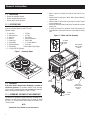 6
6
-
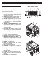 7
7
-
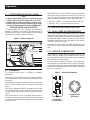 8
8
-
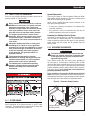 9
9
-
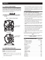 10
10
-
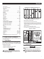 11
11
-
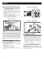 12
12
-
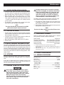 13
13
-
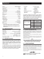 14
14
-
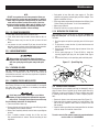 15
15
-
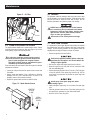 16
16
-
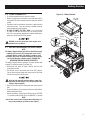 17
17
-
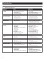 18
18
-
 19
19
-
 20
20
-
 21
21
-
 22
22
-
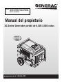 23
23
-
 24
24
-
 25
25
-
 26
26
-
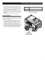 27
27
-
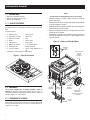 28
28
-
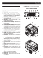 29
29
-
 30
30
-
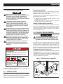 31
31
-
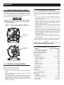 32
32
-
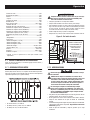 33
33
-
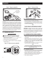 34
34
-
 35
35
-
 36
36
-
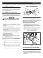 37
37
-
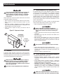 38
38
-
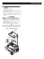 39
39
-
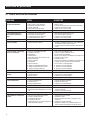 40
40
-
 41
41
-
 42
42
-
 43
43
-
 44
44


Generac XG7000E 0057980 Manual de usuario
- Categoría
- Generadores de poder
- Tipo
- Manual de usuario
en otros idiomas
- English: Generac XG7000E 0057980 User manual