Kichler Lighting 44016OZ Manual de usuario
- Tipo
- Manual de usuario

IS-44016-US
We’re here to help 866-558-5706
Hrs: M-F 9am to 5pm EST
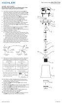
3) Pass xture wire through hole in canopy[D]. Pass
threaded pipe on end of swivel up through hole in
canopy.
4) Pass xture wire through lockwasher[E]. Thread
lockwasher onto end of threaded pipe protruding from
inside canopy.
5) Pass xture wire through hexnut[F]. Thread hexnut onto
end of threaded pipe.
6) Find the appropriate threaded holes on mounng
strap[G]. Assemble mounng screws[H] into threaded
holes.
7) Aach mounng strap to outlet box[I] using the strap
mounng screws[J]. Mounng strap can be adjusted to
suit posion of xture.
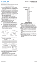
8) Grounding instrucons: (See Illus. a or b).
a) On xtures where mounng strap is provided with a
hole and two raised dimples, wrap ground wire from
outlet box around green ground screw, and thread
into hole.
b) On xtures where a cupped washer is provided,
aach ground wire from outlet box under cupped
washer and green ground screw, then thread into
mounng strap.
If xture is provided with ground wire, connect xture
ground wire to outlet box ground wire with wire
connector (Not provided) aer following the above steps.
Never connect ground wire to black or white power
supply wires.
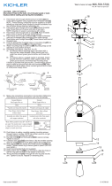
9) Make wire connecon. Reference chart below for correct
connecons and wire accordingly.
Connect Black or Red
Supply Wire to:
Connect White Supply
Wire to:
Black White
*Parallel cord (round &
smooth)
*Parallel cord (square &
ridged)
Clear, Brown, Gold or
Black without Tracer
Clear, Brown, Gold or Black
with Tracer
Insulated wire (other
than green) with copper
conductor
Insulated wire (other
than green) with silver
conductor
*Note: When parallel wire (SPT
1 & SPT 2) are used. The neutral
wire is square shaped or ridged
and the other wire will be round
in shape or smooth (See illus.)
Neutral Wire
10) Push xture to ceiling, carefully passing mounng screws
through holes in canopy. NOTE: Be certain wires do not
get pinched between canopy and ceiling.
11) Use knobs[K] and lockwashers[L] to secure canopy.
Tighten to secure.
12) Carefully raise glass[M] to the xture. Slip the opening
over the socket[N] and t the glass against the socket.
13) Slide glass spacer[P] over socket and thread the socket
ring onto the socket. Tighten socket ring to secure glass
in place. (DO NOT over ghten).
14) Insert recommended bulb. (Not supplied).
15) Take the two (2) decorave rings and place on top of the
half ball on top of the xture as shown, and secure into
place using the machine screws.
GREEN GROUND
SCREW
CUPPED
WASHER
OUTLET BOX
GROUND
FIXTURE
GROUND
DIMPLES
WIRE CONNECTOR
OUTLET BOX
GROUND
GREEN GROUND
SCREW
FIXTURE
GROUND
a
b
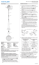
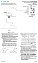
Fixture Diagram
Parts List
Cauons
CAUTION – RISK OF SHOCK –
Disconnect Power at the main circuit breaker panel or main
fusebox before starng and during the installaon.
WARNING:
This xture is intended for installaon in accordance
with the Naonal Electrical Code (NEC) and all local code
specicaons. If you are not familiar with code requirements,
installaon by a cered electrician is recommended.
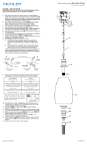
Installaon Instrucons
[A] Stems
[B] Short
Threaded
Tubes
[C] Swivel
[D] Canopy
[E] Lockwasher
[F] Hexnut
[G] Mounting
Strap
[H] Mounting
Screws
[I] Outlet Box
[J] Strap
Mounting
Screws
[K] Knobs
[L] Lockwashers
[M] Glass
[N] Socket
[O] Glass Retainer
[P] Spacer
[Q] Arm
Assembly
1) Pass xture wire through desired amount of stems[A]
and screw stems together using supplied short threaded
tubes[B].
NOTE: Thread locking compound must be applied to
all stem threads as noted with (4) symbol to prevent
accidental rotaon of xture during cleaning, relamping,
etc.
2) Pass xture wire through end of swivel[C] without
threaded pipe. Thread that end of swivel onto end of last
stem. Note the direcon of swivel in accordance with
ceiling.
Installaon Instrucons (connued)
M
O
N
I
G
D
H
K
J
L
►
A
►
B
►►
►►
►
►
►
C
F
E
P
Q
R

IS-44016-US
Estamos aquí para ayudarle 866-558-5706
Horario: Lunes-Viernes 9am a 5pm EST (hora ocial del este)
3) Pasar del luminario a través del oricio en el pabellón[D].
Pasar tubo roscado en el extremo del eslabón giratorio a
través del oricio en el pabellón.
4) Pasar el cable a través del agujero en la arandela de
seguridad[E]. Tornillo de la arandela de seguridad en el
extremo roscado del tubo desde el interior de la cubierta.
5) Pasar del luminario a través del agujero de la tuerca
hexagonal[F]. Tuerca hexagonal rosca al extremo del
tubo roscado.
6) Encuentre los oricios roscados adecuados en la correa
de montaje[G]. Montar los tornillos de montaje[H] en los
oricios roscados.
7) Fije la correa de montaje a la caja de salida[I] con
los tornillos de montaje de la correa[J]. La correa de
montaje puede ajustado para adaptarse a la posición del
aparato.
8) Instrucciones de conexión a erra solamente para los
Estados Unidos. (Vea la ilustracion a o b).
a) En las lámparas que enen el eje, de montaje con
un agujero y dos hoyuelos realzados, enrollar el
alambre a erra de la caja tomacorriente alrededor
del tornillo verde y pasarlo por el aquiero.
b) En las lámparas con una arandela acopada, jar el
alambre a erra de la caja tomacorriente del ajo de la
arandela acoada y tornillo verde, y paser por el eje
de montaje.
Si la lámpara viene con alambre a erra, conecter el
alambre a erra de la lámpara al alambre a erra de la
caja tomacorriente con un conector de alambres (No
incluido) espués de seguir los pasos anteriores. Nunca
conectar el alambra a erra a los alambres eléctros negro
o blanco.
9) Haga les conexiones de los alambres. La tabla de
referencia de abajo indica las conexiones correctas y los
alambres correspondientes.
Conectar el alambre de
suministro negro o rojo al
Conectar el alambre de
suministro blanco al
Negro Blanco
*Cordon paralelo (redondo
y liso)
*Cordon paralelo (cuadrado
y estriado)
Claro, marrón, amarillio
o negro sin hebra
idencadora
Claro, marrón, amarillio
o negro con hebra
idencadora
Alambre aislado (diferente
del verde) con conductor
de cobre
Alambre aislado (diferente
del verde) con conductor
de plata
*Nota: Cuando se uliza alambre
paralelo (SPT 1 y SPT 2). El alambre
neutro es de forma cuadrada o
estriada y el otro alambre será
de forma redonda o lisa. (Vea la
ilustracíón).
Hilo Neutral
10) Empuje el artefacto al techo, pasando cuidadosamente
los tornillos de montaje a través de los agujeros en el
escudete. NOTA: Conrme que todos los cables queden
dentro del escudete, y que el borde de éste no los apriete
contra el techo.
11) Ulice perillas [K] y arandelas de seguridad [L] para
asegurar el escudete. Ajuste para asegurar.
12) Suba cuidadosamente el vidrio [M] al artefacto. Pase la
abertura sobre el portalámparas [N] y ajuste el vidrio
contra el escudete.
13) Pase el espaciador de vidrio [P] sobre el portalámparas
y enrosque el anillo del portalámparas en el
portalámparas. Ajuste el anillo del portalámparas para
asegurar el vidrio en su lugar. (No ajuste demasiado).
14) Inserte las bombillas recomendadas. (No se proveen).
15) Tome los dos (2) anillos decoravos y colóquelos encima
de la media esfera sobre el artefacto como se indica, y
asegure en su lugar usando los tornillos para metal.
ARANDELA
CONCAVA
TIERRA DE LA
CAJA DE SALIDA
TORNILLO DE TIERRA,
VERDE
DEPRESIONES
TIERRA
ARTEFACTO
CONECTOR DE ALAMBRE
TIERRA DE LA
CAJA DE SALIDA
TORNILLO DE TIERRA,
VERDE
TIERRA
ARTEFACTO
a
b
Diagrama de Accesorios
Lista de Partes
[A] Deseada de
Tallos
[B] Tubos Roscados
Cortos
[C] Giratorio
[D] Pabellón
[E] Arandela de
Seguridad
[F] Tuerca
Hexagonal
[G] Correa de
Montaje
[H] Tornillos de
Montaje
[I] Caja de Salida
[J] Los tornillos de
montaje de la
correa
[K] Perillas
[L] Arandelas de
Seguridad
[M] Vidrio
[N] Portalámparas
[O] Annilo de
retención del
vidrio
[P] Espaciador de
vidrio
[Q] Ensamble del
brazo
Precauciones
PRECAUCIÓN – RIESGO DE DESCARGA ELÉCTRICA –
Desconecte la electricidad en el panel principal del
interruptor automáco o caja principal de fusibles antes de
comenzar y durante la instalación.
ADVERTENCIA:
Este accesorio está desnado a la instalación de
acuerdo con el Naonal Electrical Code (NEC) y todas las
especicaciones del código local. Si no está familiarizado
con los requisitos del código, la instalación se recomienda
un electricista cercado.
Instrucciones de Instalación
1) Pase el cable del accesorio a través de la candad
deseada de tallos[A] y el tornillo se unen ulizando tubos
roscados cortos suministrados[B]. NOTA: El compuesto
de bloqueo de rosca debe aplicarse a todos los hilos del
vástago como se indica con el símbolo de echa para
evitar la rotación accidental del disposivo durante la
limpieza, relamping, etc.
2) Pasar del luminario al alambre a través del extremo del
eslabón giratorio[C] sin tubo. Ese extremo del eslabón
giratorio en el extremo del úlmo vástago del hilo de
rosca. NOTA: Dirección de giro de conformidad con el
techo.
M
O
N
I
G
D
H
K
J
L
►
A
►
B
►►
►►
►
►
►
C
F
E
P
Q
R
-
 1
1
-
 2
2


Kichler Lighting 44016OZ Manual de usuario
- Tipo
- Manual de usuario
en otros idiomas
- English: Kichler Lighting 44016OZ User manual
Artículos relacionados
-
 Kichler Lighting 44270PN Manual de usuario
-
 Kichler Lighting 44286WWW Manual de usuario
-
 Kichler Lighting 43051PN Manual de usuario
-
 Kichler Lighting 44053NI Manual de usuario
-
 Kichler Lighting 42798NI Manual de usuario
-
 Kichler Lighting 43090CLP Manual de usuario
-
 Kichler Lighting 44255WZC Manual de usuario
-
 Kichler Lighting 49776BK Manual de usuario
-
 Kichler Lighting 49835AZ Manual de usuario
-
Kichler Lighting 44183VTGLED Manual de usuario


