
Active Servo
Technology
OWNER’S MANUAL
MODE D’EMPLOI
BEDIENUNGSANLEITUNG
BRUKSANVISNING
MANUALE DI ISTRUZIONI
MANUAL DE INSTRUCCIONES
GEBRUIKSAANWIJZING
POWER
PUSH OPEN
OPEN
/
CLOSE
CD
TUNER TAPE
/
MD VCR VIDEO 1 VIDEO 2
/
VOLUME
MHz
K
Hz
TRACK PRESET
PRO LOGIC DSP OFF
ENHANCED MONO MOVIE
ROCK CONCERT VIDEO
DISCO HALL STADIUM
TIMER
F REP
SLEEP
AUTO ST
MEMORY
PTY HOLD
CINEMA DSP
Home Theater Compact System
Salle de cinéma domestique compacte
Home Theater Kompaktanlage
Kompakt anläggning av Home Theater-typ
Sistema compatto di sala cinematografica ad uso domestico
Sistema compacto del Cine en el Hogar
Thuis Theater Compact Systeem
B G L R

SUPPLIED ACCESSORIES
●
After unpacking, check that the following parts are contained.
ACCESSOIRES FOURNIS
●
Après le déballage, vérifier que les pièces suivantes sont incluses.
MITGELIEFERTES ZUBEHÖR
●
Nach dem Auspacken überprüfen, ob die folgenden Teile vorhanden sind.
MEDFÖLJANDE TILLBEHÖR
●
Kontrollera efter det apparaten packats upp att följande delar finns med.
ACCESSORI IN DOTAZIONE
●
Verificare che tutte le parti seguenti siano contenute nell’imballaggio dell’apparecchio.
ACCESORIOS INCLUIDOS
●
Desembale el aparato y verificar que los siguientes accesorios están en la caja.
BIJGELEVERDE ACCESSOIRES
●
Controleer na het uitpakken of de volgende onderdelen voorhanden zijn.
●
Remote control transmitter
●
Télécommande
●
Fernbedienung
●
Fjärrkontroll
●
Telecomando
●
Controlador remoto
●
Afstandbediening
●
Batteries (size AA, UM/SUM-3, R6, HP-7)
●
Piles (format AA, UM/SUM-3, R6, HP-7)
●
Batterien (Größe AA, UM/SUM-3, R6, HP-7)
●
Batterier (Storl. AA, UM/SUM-3, R6, HP-7)
●
Batterie (dimensioni AA, o UM/SUM-3, o R6, o HP-7)
●
Pilas (tamaño AA, tipo UM/SUM-3, R6, HP-7)
●
Batterijen (maat AA, UM/SUM-3, R6, HP-7)
●
AM (MW/LW) loop antenna
●
Cadre-antenne AM (PO/GO)
●
MW/LW-Rahmenantenne
●
AM (MV/LV) ramantenn
●
Antenna ad anello per
AM (MW e LW)
●
Antena de cuadro
AM (OM/OL)
●
AM (MW/LW) lusantenne
●
Indoor FM antenna
●
Antenne intérieure FM
●
UKW-Innenantenne
●
FM inomhusantenn
●
Antenna FM per interni
●
Antena interior de FM
●
FM binnenantenne
●
Audio connection cord
●
Câble de connexion audio
●
Audio-Anschlußkabel
●
Audio anslutningssladdar
●
Cavo di collegamento audio
●
Cable de conexión de audio
●
Audio aansluitkabel
●
System connector cable
●
Câble de connexion du système
●
System-Verbindungskabel
●
Systemkontrollkabel
●
Cavo di collegamento del sistema
●
Cable de conexión del sistema
●
Systeemaansluitkabel
●
Speaker cords
●
Câbles d’enceintes
●
Lautsprecheranschlußkabel
●
Högtalarledningar
●
Cavi per gli altoparlanti
●
Cables de los altavoces
●
Luidsprekerdraden
●
Mounting brackets
●
Supports de montage
●
Befestigungshalterungen
●
Monteringsfästen
●
Staffe di montaggio
●
Ménsulas de instalación
●
Montagesteunen
●
Screws
●
Vis
●
Schrauben
●
Skruvar
●
Viti
●
Tornillos
●
Schroeven
●
Tag sheet (for speaker cords)
●
Plaquette d’étiquettes (pour les cordons d’enceinte)
●
Markierungsflagge (für Lautsprecherkabel)
●
Etikettark (för högtalarledningar)
●
Cartellini (per i cavi degli altoparlanti)
●
Hoja de etiquetas
(para los cables de altavoz)
●
Etikettenvel
(voor luidsprekerkabels)
TUNER
CD
DSP
AMP
2 3
(A)
(B)
2 5
(C)
FRONT
L
FRONT
L
FRONT
L
FRONT
L
FRONT
R
FRONT
R
FRONT
R
FRONT
R
CENTER
C
CENTER
C
CENTER
C
CENTER
C
REAR
L
REAR
L
REAR
L
REAR
L
REAR
R
REAR
R
REAR
R
REAR
R
(A)
(B)

E-1
English
ENGLISH
INTRODUCTION
Thank you for purchasing this YAMAHA product. We hope it will give you many years of trouble-free enjoyment. For
the best performance, read this manual carefully. It will guide you in operating your YAMAHA product.
A Brief Guide to Proper Use of This System and
The Owner’s Manual
The following procedure shows you how to begin using this system and the
owner’s manual from the time just after you bought this system.
1. Unpack the package, and check the contents. (Refer to the inside of the cover and
page 6.)
2. Read “PRECAUTIONS” on this manual (on pages 3 to 5) first of all.
3. To understand this system, see pages 6 to 8.
4. Position and install all units in this system (see pages 9 to 11), and then make
connections (see pages 12 to 17).
Do not plug in this system until all connections are completed.
5. Before listening to a source, make some adjustments. (See pages 24 to 27.)
6. Begin listening to a source. (See pages 28 to 29.)
● To listen to a compact disc, see pages 30 to 32.
● To listen to a radio program, see pages 33 to 37.
(For U.K. and Europe models only, see pages 33 to 43.)
● To listen to or watch a source played on an external unit, see page 44.
7. To enjoy listening to a source with surround sound effects, see pages 45 to 48.
●● To use the built-in timer, see pages 49 to 51.
●● If you want to know the function of a button, switch or indicator, see pages 18 to 23.

Page
PRECAUTIONS........................................................3-4
NOTES ABOUT THE REMOTE CONTROL
TRANSMITTER............................................................5
SYSTEM CONFIGURATION .......................................6
FEATURES..................................................................7
DIGITAL SOUND FIELD PROCESSOR (DSP)...........8
SETTING UP THE SPEAKERS..............................9-11
CONNECTIONS....................................................12-17
CONTROLS AND THEIR FUNCTIONS................18-23
TURNING THE POWER TO THIS SYSTEM ON
OR IN THE STANDBY MODE...................................24
SETTING THE CLOCK..............................................25
ADJUSTING BRIGHTNESS OF THE DISPLAY .......25
SPEAKER BALANCE ADJUSTMENT.................26-27
Page
BASIC LISTENING OPERATIONS......................28-29
COMPACT DISC PLAYER OPERATION.............30-32
TUNING OPERATION..........................................33-37
RECEIVING RDS STATIONS
<U.K. and Europe models only>.......................38-43
OPERATING EXTERNAL UNITS
CONNECTED WITH THIS SYSTEM..........................44
USING DIGITAL SOUND FIELD PROCESSOR
(DSP).....................................................................45-48
TIMER PLAY.........................................................49-50
SLEEP TIMER OPERATION.....................................51
TROUBLESHOOTING...............................................52
SPECIFICATIONS................................................53-54
PRECAUTIONS
LISTENING TO A COMPACT DISC
LISTENING TO A RADIO PROGRAM
LISTENING TO A SOURCE ON AN EXTERNAL UNIT
USING DIGITAL SOUND FIELD PROCESSOR (DSP)
HOW TO USE THE BUILT-IN TIMER
TROUBLESHOOTING
SPECIFICATIONS
RECEIVING RDS STATIONS
<
U.K. and Europe models only
>
OUTLINE OF THIS SYSTEM
SETTING UP THE SPEAKERS
CONNECTIONS
CONTROLS AND THEIR FUNCTIONS
ADJUSTMENTS BEFORE LISTENING OPERATIONS
TURNING THE POWER TO THIS SYSTEM ON
OR IN THE STANDBY MODE
ENJOYING LISTENING TO A SOURCE
E-2
CONTENTS

E-3
English
PRECAUTIONS
■ To assure the finest performance, please read this
manual carefully. Keep it in a safe place for future
reference.
■ Choose the installation location of this unit carefully.
Avoid placing it in direct sunlight or close to a source
of heat. Also avoid locations subject to vibration and
excessive dust, heat, cold or moisture. Keep it away
from sources of hum such as transformers and
electric motors.
■ Do not operate this unit upside-down. It may
overheat, possibly causing damage.
■ Never open the cabinet. If something drops into the
set, contact your dealer.
■ The openings on the surface of the power
amplifier/subwoofer unit assure proper ventilation of
the unit. If these openings are obstructed, the
temperature inside the unit will rise rapidly.
Therefore, avoid placing objects against these
openings, and install the unit in well-ventilated
condition. Make sure to allow a space of at least 10
cm behind, 10 cm on the both sides and 20 cm
above the top panel of the unit, and never use the
unit with the unit laid down on the floor. Otherwise it
may not only damage the unit, but also cause fire.
■ Always make the volume setting to minimum before
starting an audio source play: increase the volume
gradually to an appropriate level after play has
started.
■ When not planning to use this unit for long periods of
time (ie., vacation, etc.), disconnect the AC power
plug from the wall outlet.
■ Grounding or polarization – Precautions should be
taken so that the grounding or polarization of the unit
is not defeated.
■ Do not use force on switches, controls or connection
wires. When moving the unit, first disconnect the
power plug and the wires connected to other
equipment. Never pull the wire itself.
■ Do not attempt to clean the unit with chemical
solvents; this might damage the finish. Use a clean,
dry cloth.
■ Be sure to read the “TROUBLESHOOTING” section
regarding common operating errors before
concluding that the unit is faulty.
■ To prevent lightning damage, disconnect the AC
power plug and the antenna cable when there is an
electrical storm.
■ Do not plug the AC power plug to the wall socket
before you finish all connections.
■ The voltage to be used must be the same as that
specified on this unit. Using this unit with a higher
voltage than that which is specified is dangerous and
may result in a fire or other type of accident causing
damage. YAMAHA will not be held responsible for
any damage resulting from use of this unit with a
voltage other than that which is specified.
■ The sound level at a given volume setting depends
on speaker location and other factors. Care should
be taken to avoid exposure to sudden high levels of
sound, which may occur when turning on the unit
with the volume setting at high, and to continuous
high levels of sound.
■ Sudden temperature changes and storage or
operation in an extremely humid environment may
cause condensation inside the unit.
Condensation can cause the unit to malfunction.
To eliminate condensation:
•
CD pickup
Leave the power on with no disc in the unit until
normal playback is possible (about 1 hour).
•
Remote control
Wipe off condensation on the transmitter window
with a soft cloth before operating the unit.
■ Secure placement or installation is the owner’s
responsibility.
YAMAHA shall not be liable for any accident
caused by improper placement or installation of
this system.
IMPORTANT
Please record the serial number of this unit in the
space below.
Serial No.:
The serial number is located on the rear of the unit.
Retain this Owner’s Manual in a safe place for future
reference.
WARNING
TO REDUCE THE RISK OF FIRE OR ELECTRIC
SHOCK, DO NOT EXPOSE THIS APPLIANCE TO
RAIN OR MOISTURE.
PRECAUTIONS: READ THIS BEFORE OPERATING THIS SYSTEM

E-4
WARNING
To reduce the risk of fire or electric shock, do not
expose this unit to rain or moisture.
To avoid electrical shock, do not open the cabinet.
Refer servicing to qualified personnel only.
NOTE
Please check the copyright laws in your country to
record from records, compact discs, radio, etc.
Recording of copyright material may infringe
copyright laws.
For U.K. customers
If the socket outlets in the home are not suitable for the
plug supplied with this appliance, it should be cut off
and an appropriate 3 pin plug fitted. For details, refer to
the instructions described below.
Note: The plug severed from the mains lead must be
destroyed, as a plug with bared flexible cord is
hazardous if engaged in a live socket outlet.
SPECIAL INSTRUCTIONS FOR U.K. MODEL
IMPORTANT:
The wire in the mains lead are coloured in
accordance with the following code:
Blue: NEUTRAL
Brown: LIVE
The colours of the wires in the mains lead of this
apparatus may not correspond with the coloured
markings identifying the terminals in your plug.
Proceed as follows: the wire which is coloured BLUE
must be connected to the terminal which is marked
with the letter N or coloured BLACK. The wire which
is coloured BROWN must be connected to the
terminal which is marked with the letter L or coloured
RED. Making sure that neither core is connected to
the earth terminal of the three pin plug.
CAUTION 1
Use of controls or adjustments or performance of
procedures other than those specified herein may
result in hazardous radiation exposure.
CAUTION 2
As the laser beam used in this unit is harmful to the
eyes, do not attempt to disassemble the cabinet.
Refer servicing to qualified personnel only.
Laser component in this product is capable of
emitting radiation exceeding the limit for Class 1.
PRECAUTIONS
This unit is classified as a
CLASS 1 LASER product.
The CLASS 1 LASER
PRODUCT label is located
on the rear exterior.
Laser Diode Properties
•
Material: GaAlAs
•
Wavelength: 780nm
•
Emission Duration: continuous
•
Laser Output: max. 44.6µW*
* This output is the value measured at a distance of
about 200mm from the objective lens surface on the
Optical Pick-up Block.
CLASS 1 LASER PRODUCT
This system is not disconnected from the AC power
source as long as it is connected to the wall outlet,
even if this system itself is turned off.
In this state, this system is designed to consume a
very small quantity of power.
VOLTAGE SELECTOR (General model only)
The voltage selector on bottom of the power
amplifier/subwoofer (SW-AV1) must be set for
your local main voltage BEFORE plugging into
the AC main supply.
Voltages are 110/120/220/240V AC, 50/60 Hz.
240V
VOLTAGE
SELECTOR
CAUTION (FOR CANADA MODEL)
TO PREVENT ELECTRIC SHOCK, MATCH WIDE
BLADE OF PLUG TO WIDE SLOT AND FULLY
INSERT.
FOR CANADIAN CUSTOMER
THIS CLASS B DIGITAL APPARATUS MEETS ALL
REQUIREMENTS OF THE CANADIAN
INTERFERENCE-CAUSING EQUIPMENT
REGULATIONS.

E-5
English
Loading the batteries for the
remote control transmitter
1
Remove the battery compartment cover.
(Slide the cover in the direction of the arrow.)
2 Insert 2 “AA” size batteries (UM/SUM-3, R6, HP-7 or
equivalent) into the battery compartment.
* Installing the batteries improperly may cause
failure.
3 Replace the battery compartment cover.
Precautions for battery use
•
Insert the batteries according to the direction
indicated in the battery compartment.
•
Replace all batteries with new ones at the same
time.
•
Remove the batteries if they are weak or if the unit is
not in use for long periods.
•
Don’t mix normal batteries with rechargeable
batteries.
Proper use of the remote control
transmitter
Aim (within the range of 60° with no obstacles) the
remote control transmitter at the remote control sensor
and operate as shown.
Notes concerning use
•
Replace the batteries if control distance decreases
or operation becomes unstable.
•
Periodically clean the transmitter window on the
remote control transmitter and the sensor on the
main unit with a soft cloth.
•
Exposing the sensor on the main unit to strong light
(especially an inverter type of fluorescent lamp etc.)
may interfere with operation. In this case, reposition
the main unit to avoid direct lighting.
•
Keep the remote control transmitter away from
moisture, excessive heat, shock and vibrations.
•
The remote control transmitter’s usable range is
within 0.2m (8”) and 6m (20’) away from the sensor.
PRECAUTIONS
NOTES ABOUT THE REMOTE CONTROL TRANSMITTER
2
1
3
MINI COMPONENT SYSTEM AV–1
POWER
PUSH OPEN
OPEN
/
CLOSE
CD
TUNER TAPE
/
MD VCR VIDEO 1 VIDEO 2
/
VOLUME
MHz
K
Hz
TRA CK PRESET
PRO LOGIC DSP OFF
ENHANCED MONO MOVIE
ROCK CONCERT VIDEO
DISCO HALL STADIUM
TIMER
F REP
SLEEP
AUTO ST
MEMORY
PTY HOLD
30°
30°
Remote control sensor
Within approximately
6 m (19.7 feet)

MINI COMPONENT SYSTEM AV–1
POWER
PUSH OPEN
OPEN
/
CLOSE
CD
TUNER TAPE
/
MD VCR VIDEO 1 VIDEO 2
/
VOLUME
MHz
K
Hz
TRACK PRESET
PRO LOGIC DSP OFF
ENHANCED MONO MOVIE
ROCK CONCERT VIDEO
DISCO HALL STADIUM
TIMER
F REP
SLEEP
AUTO ST
MEMORY
PTY HOLD
Active Servo
Technology
6CH POWER AMPLIFIER
ACTIVE SERVO PROCESSING SUBWOOFER
E-6
OUTLINE OF THIS SYSTEM
This system is a multi-channel audio system which consists of the units shown below.
By driving 6 speakers, the built-in digital sound field processor (DSP) creates various kinds of Yamaha original digital
sound fields simulating an actual concert hall, live house, etc. When watching a movie source, the built-in Dolby Pro
Logic Surround decoder and the digital sound field processor turns your room into a movie theater with tremendous
impact.
Ultralow bass reproduced by the subwoofer (SW-AV1) makes sound more real and more powerful.
The built-in CD player and tuner provide you with effortless operation and high performance.
You will be given great enjoyment in listening to music and watching TV with this system.
SW-AV1
(6 channel power amplifier
and Active Servo Processing
Subwoofer system)
NX-AV1
(Full range speakers used for front,
center and rear speakers)
TCD-AV1
(Main control unit
including Tuner, CD
player and Digital Sound
Field Processor)
SYSTEM CONFIGURATION

E-7
English
OUTLINE OF THIS SYSTEM
The System
● 6 Speaker Multi-Channel Audio
System Including Two Front
Speakers, One Center Speaker, Two
Rear Speakers and One Subwoofer
● Minimum RMS Output Power per
Channel
Front L, R: 30W + 30W (6Ω) RMS
Output
Power, 10% THD,
1 kHz
Center
: 30W (6Ω) RMS Output
Power, 10% THD, 1 kHz
Rear L, R: 30W + 30W (6Ω) RMS
Output Power, 10% THD, 1
kHz
Subwoofer
: 50W (4Ω) RMS Output
Power, 10% THD, 100 Hz
● Active Servo Processing Subwoofer
System for Super Low Bass
Reproducing (SW-AV1)
● Simple and Easy Operating Methods
● Direct Playback by a Simple
Operation
● Automatic Function to Turn the
System into the Standby Mode
● Adjustable Display Brightness
● Multi-Use Timer/Sleep Timer
● 5 External Audio/Video Component
Connecting Capability
● On Screen Display Function (Displays
Volume Setting, Speaker Balance
Adjustment, Program Names, etc. on
the TV Monitor)
● Remote Control Capability
Compact Disc Player
● Single Track/Entire Disc Repeat Play
Tuner
● 40 Station Random Access Preset
Tuning
● 40 Station Automatic Preset Tuning
<Europe and U.K. models only>
● Multi-Functions for RDS Broadcast
Reception
Sound Field Processor Including
Dolby Pro Logic Surround
Decoder
● Digital Sound Field Processor
(Programs: STADIUM, DISCO,
CONCERT HALL, ROCK CONCERT,
MONO MOVIE, CONCERT VIDEO)
● Dolby Pro Logic Surround Decoder
(Program: DOLBY PRO LOGIC)
● CINEMA DSP:
Theater-like Sound Experience by the
Combination of Dolby Pro Logic and
YAMAHA DSP Technology
(Program: DOLBY PRO LOGIC
ENHANCED)
● Automatic Input Balance Control for
Dolby Pro Logic Surround
● Test Tone Generator for Easier
Speaker Balance Adjustment
FEATURES

E-8
OUTLINE OF THIS SYSTEM
DIGITAL SOUND FIELD PROCESSOR (DSP)
The Digital Sound Field Processor (DSP) built into this system takes advantage of Yamaha’s undisputed leadership in
the field of digital audio processing to bring you a whole new world of listening experiences. Follow the instructions in
this manual carefully when setting up your system, and this unit will sonically transform your room into a wide range of
listening environments –movie theater, concert hall, and so on. In addition, you get incredible realism from sources
encoded with Dolby Surround using the built-in Dolby Pro Logic Surround Decoder.
Please read this operation manual carefully and store it in a safe place for later reference.
Digital Sound Field Processing
What is it that makes live music so good? Today’s
advanced sound reproduction technology lets you get
extremely close to the sound of a live performance, but
chances are you’ll still notice something missing: the
acoustic environment of the live concert hall. Extensive
research into the exact nature of the sonic reflections
that create the ambience of a large hall has made it
possible for Yamaha engineers to bring you this same
sound in your own listening room, so you’ll feel all the
sound of a live concert.
Furthermore, our technicians, armed with sophisticated
measuring equipment, have even made it possible to
capture the acoustics of a variety of venues such as an
actual concert hall, theater, etc. to allow you to
accurately recreate one of several actual live
performance environments, all in your own home.
Dolby Pro Logic Surround
This unit employs a Dolby Pro Logic Surround decoder
similar to professional Dolby Stereo decoders used in
many movie theaters. By using the Dolby Pro Logic
Surround decoder, you can experience the dramatic
realism and impact of Dolby Surround movie theater
sound in your own home. Dolby Pro Logic employs a
four channel five speaker system. The Pro Logic
Surround system divides the input signal into four levels:
the left and right main channels, the center channel
(used for dialog), and the rear surround sound channels
(used for sound effects, background noise, and other
ambient noises). The center channel allows listeners
seated in even less-than-ideal positions to hear the
dialog originating from the action on the screen while
experiencing good stereo imaging.
Dolby Surround is encoded on the sound track of pre-
recorded video tapes, laser discs, and some TV/cable
broadcasts. When you play a source encoded with Dolby
Surround on this unit, the Dolby Pro Logic Surround
decoder decodes the signal and distributes the
surround-sound effects.
This Dolby Pro Logic Surround Decoder employs a
digital signal processing system. This system improves
the stability of sound at each channel and minimizes
crosstalk between channels, so that positioning of
sounds around the room is more accurate compared
with conventional analog signal processing systems.
In addition, this unit features a built-in automatic input
balance control. This always assures you the best
performance without manual adjustment.
Manufactured under license from Dolby Laboratories
Licensing Corporation. “Dolby”, “Pro Logic”, and the
double-D symbol are trademarks of Dolby Laboratories
Licensing Corporation.
Dolby Pro Logic Surround + DSP
Dolby Surround sound system shows its full ability in a
large movie theater, because movie sounds are
originally designed to be reproduced in a large movie
theater using many speakers. It is difficult to create a
sound environment similar to that of a movie theater in
your listening room, because the room size, materials of
inside walls, the number of speakers, etc. of your
listening room is much different from those of a movie
theater.
Yamaha DSP technology made it possible to present
you with nearly the same sound experience as that of a
large movie theater in your listening room by
compensating for lack of presence and dynamics in your
listening room with its original digital sound fields
combined with Dolby Surround sound field.
The combination of Dolby Pro Logic Surround and DSP
is used on the sound field program “ PRO LOGIC
ENHANCED”.
The YAMAHA “CINEMA DSP” logo indicates these
programs are created by the combination of Dolby Pro
Logic and YAMAHA DSP technology.
CINEMA DSP

E-9
English
SETTING UP THE SPEAKERS
SETTING UP THE SPEAKERS
Speaker configuration
This system employs a 6 speaker configuration: 2 front
speakers, 2 rear speakers, a center speaker and a
subwoofer.
The front speakers are used for the main source sound
plus the effect sounds. The rear speakers are used for
the effect and surround sounds, and the center speaker
is for the center sounds (dialog etc.). The subwoofer is
for reinforcing low frequencies of the main source sound
and the center sounds.
Rear L
Rear R
TV set
Front R
Subwoofer
Center
Front L
Rear L
Rear R
Placing speakers
Front speakers: On both sides of the TV and in
almost the same height as the TV.
Rear speakers: Behind your listening position,
facing slightly inward. Nearly six
feet (approx. 1.8 m) up from the
floor.
Center speaker: Precisely between the front
speakers.
Subwoofer: The position of the subwoofer is not
so critical because low bass tones
are not highly directional.
Before you make connections, place all units in this system in their proper positions respectively. Above all, the
positioning of speakers are important, because it controls the whole sound quality of this system.
Position the speakers on the basis of your listening position by following instructions on this section.
Front L Center Front R
Rear L Rear R
Subwoofer

E-10
SETTING UP THE SPEAKERS
■ Mounting the front and center
speakers
Place the front speakers on a rack or on a shelf, and
place the center speaker on top of the TV or on a shelf
or inside the TV rack so that it is stabilized.
To obtain more stability and usefulness, we recommend
that you mount those speakers on the provided
mounting brackets (type A).
To mount speakers on the mounting
brackets (type A)
1 Attach the bracket to bottom of the speaker by using
the provided screw (type A).
2 Turn and/or slide the speaker on the bracket
according as you desire, and after that, tighten the
screw.
Note
Though this speaker is a magnetically shielded
type, there may be some influence on a TV picture
depending on the type of TV or the placement of the
speaker. In such a case, place the speaker apart
from the TV so that there is no influence on TV
picture.
■ Mounting the rear speakers
Mount the rear speakers on a shelf, rack or on the floor
directly, or hang them on the wall.
To mount the rear speakers on a wall by
using the provided mounting brackets (type
B)
Note
It is recommended that you connect the speaker cords
to the speaker’s terminals before attaching the bracket
to the speaker.
1 Attach the bracket to bottom of the speaker by using
the provided screw (type B).
2 Turn and/or slide the speaker on the bracket
according as you desire, and after that, tighten the
screw.
Mounting
bracket
(type A)
Screw
(type A)
1
2
1
2
Screw
(type B)
Mounting
bracket
(type B)

E-11
English
3 Fasten screws into a firm wall or wall support as
shown in the figure, and hang the holes of the
mounting bracket on the protruding screws.
* Make sure that the screws are caught by a narrow
part of the holes securely.
Note
If desired, you can hang the speaker on the protruding
screws on the wall without using the bracket.
WARNING:
● Each speaker weighs 0.7 kg (1 lbs. 9 oz.). Do not
mount them on thin plywood or soft wall surface
material, as the screws may come out of the
flimsy surface, causing the speakers to fall down
and be damaged, or result in personal injury.
● Do not fasten the speakers to wall with nails,
adhesives, or other unsound hardware. Long-
term use and vibrations may cause them to fall
down.
● To avoid accidents resulting from tripping over
loose speaker cords, fix them to the wall.
● Select a proper position on the wall to mount the
speaker and the bracket so that no one will hit
his head or face on the sticking part of the
bracket, resulting in personal injury.
SETTING UP THE SPEAKERS
65 mm
3
Tapping screw
(Available at the
hardware store)
Wall/ wall
support
Mounting
bracket
(type B)
Min.
12 mm
■ If you want to mount the speaker
on a commercially available
speaker stand
The provided mounting bracket (type C) which has 1
pair of screw holes (at an interval of 60 mm) are
available to mount the speaker on a speaker stand.
* Those screw holes can be used with M4 screws
only.
1 Attach the bracket to bottom of the speaker by using
the provided screw (type A) so that the convex part
of the bracket fits in grooved part on bottom of the
speaker as figured left.
2 Mount the speaker on the speaker stand by using
the screw holes on the bracket.
Note
The mounting bracket (type C) is provided for each of 5
speakers.
Mounting
bracket
(type C)
Screw
(type A)
60 mm

E-12
FROM TCD–AV1
FRONT
INPUT
SYSTEM
CONNECTOR
MARK
CENTER REARREAR
RL RCL
L
R
ANTENNA
FM
75
Ω
UNBAL.
GND AM
VIDEO
SIGNAL
TO SW-AV1
MARK
SYSTEM
CONNECTOR
AUDIO
OUTPUT
IN
MONITOR OUT
VIDEO 1
OUT IN
VCR
OUT IN
TAPE/MD
FROM TCD–AV1
INPUT
SYSTEM
CONNECTOR
MARK
L
R
TO SW-AV1
MARK
SYSTEM
CONNECTOR
AUDIO
OUTPUT
■ Making a system connection between the main control unit (TCD-AV1) and
the power amplifier/subwoofer (SW-AV1)
CONNECTIONS
CONNECTIONS
1 Connect the SYSTEM CONNECTOR terminals on
both units with each other by using the provided
system connector cable.
* When connecting the system connector cable to
both terminals, take notice of the directions of
each SYSTEM CONNECTOR terminal’s face.
2 Connect the AUDIO OUTPUT terminals on TCD-
AV1 to the INPUT terminals on SW-AV1 by using
the provided connection cord.
* Make sure to connect the red plug of the
connection cord to the “R” (right) terminal and
connect the white plug to the “L” terminal.
Power amplifier/subwoofer
(SW-AV1)
Main control unit (TCD-AV1)
Audio
connection
cord
(provided)
System
connector
cable
(provided)
Never plug the AC supply lead of this system into the AC outlet until all connections are
completed.
When you have finished placing or installing all units in this system, begin making connections by following
instructions on this section.
This system needs 6 kinds of connections: system connection, speaker connection, antenna connection and external
unit connection, however the order of them is not important.
1
2
Caution
Be careful not to damage
the system connector
cable by placing
something heavy on the
cable, by fixing metal
fittings on the cable, by
tugging the cable, and so
on. Damaging the cable
will lead this system to a
breakdown.

E-13
English
CONNECTIONS
Right front speaker Left front speaker Right rear speaker Center speaker Left rear speaker
■ Connecting the speakers (NX-AV1) to the power amplifier/subwoofer
(SW-AV1)
FROM TCD–AV1
FRONT
INPUT
SYSTEM
CONNECTOR
MARK
L
R
CENTER REARREAR
R L R C L
FRONT CENTER REARREAR
R L R C L
Power amplifier/subwoofer
(SW-AV1)

E-14
Connect the provided speakers (NX-AV1) to the
SPEAKERS terminals on the rear of SW-AV1.
All of the speakers (NX-AV1) are identical.
The speakers connected to the FRONT R and L
terminals should be used as the right and left front
speakers.
The speaker connected to the CENTER terminal
should be used as the center speaker.
The speakers connected to the REAR R and L
terminals should be used as the right and left rear
speakers.
Notes
● Do not connect speakers other than the provided
ones to SW-AV1.
● Use the provided speaker cords for the connections.
Normally, use the short cords to connect with the
front and center speakers, and use the long ones to
connect with the rear speakers.
● The provided tag sheet for speaker cords is useful
for preventing wrong connections between speakers
and SW-AV1.
How to Connect:
Connect the provided speaker cords between the
SPEAKERS terminals on the power
amplifier/subwoofer (SW-AV1) and the speaker
terminals on each speaker (NX-AV1) properly as
shown below. If the connections are faulty, no sound
will be heard from the speakers. Make sure that the
polarity of the speaker wires is correct, that is the + and
– markings are observed. If these wires are reversed,
the sound will be unnatural and lack bass.
As a sure method, connect the wire with a silver line to
the + terminals on both the power amplifier/subwoofer
(SW-AV1) and speaker, and connect the wire with no
line to the – terminals on both of them.
Caution
Do not let the bare speaker wires touch each other
as this could damage SW-AV1 and/or speakers.
On SW-AV1:
Red: positive (+)
Black: negative (–)
➀
Press up the tab.
➁
Insert the bare wire.
[Remove approx.
5mm (1/4”)
insulation from the
speaker wires.]
➂
Press down the tab
and secure the
wire.
On NX-AV1:
Red: positive (+)
Black: negative (–)
➀
Press the tab.
➁
Insert the bare wire.
[Remove approx.
5mm (1/4”)
insulation from the
speaker wires.]
➂
Release the tab and
secure the wire.
CONNECTIONS
➀
➁
➂
L
FRONT

E-15
English
ANTENNA
FM
75
Ω
UNBAL.
GND AM
ANTENNA
FM
75
Ω
UNBAL.
GND AM
(1)
(2)
(3)
(4)
ANTENNA
FM
75
Ω
UNBAL.
GND AM
or
Earth rod
7.5 m (25 feet)
15 m (49 feet)
ANTENNA
FM
75
Ω
UNBAL.
GND AM
VIDEO
SIGNAL
TO SW-AV1
AUDIO
OUTPUT
IN
MONITOR OUT
VIDEO 1
OUT IN
VCR
OUT IN
TAPE/MD
MARK
SYSTEM
CONNECTOR
■ Antenna connection
(1) Supplied FM antenna
Connect the FM antenna wire to the corresponding
terminal and direct the FM antenna wire to the direction
where the strongest signal can be received.
(2) Supplied AM (MW/LW) loop antenna
Connect the AM (MW/LW) loop antenna wires to the
corresponding terminals. Position the AM (MW/LW)
loop antenna for optimum reception. Place the AM
(MW/LW) loop antenna on a shelf etc., or install it on
the rack or wall with screws (not provided).
Notes
•
When static is still heard even after adjusting the
position of the AM (MW/LW) loop antenna, try
reversing the wire connections (right to left).
•
Do not place the AM (MW/LW) loop antenna on the
unit. It will result in noise generation, since the unit
is equipped with digital electronics. Place the AM
(MW/LW) loop antenna away from the unit.
(3) External FM antenna
Use an external FM antenna instead of an indoor FM
antenna if you need better reception. Consult your
dealer.
(4) External AM (MW/LW) antenna
Use an external AM (MW/LW) antenna if you need
better reception. Consult your dealer.
Note
When using an external AM (MW/LW) antenna, be
sure to keep the wire of the AM (MW/LW) loop antenna
connected.
CONNECTIONS

E-16E-16
■ Connecting external components
This system can be connected with external audio and video components. Make connections between this system
and other components using RCA pin plug connector cables correctly, that is to say L (left) to L and R (right) to R.
Also, refer to the owner’s manual for each component to be connected to this system.
CONNECTIONS
Main control unit (TCD-AV1)
Main control unit
(TCD-AV1)
Monitor TV
ANTENNA
FM
75
Ω
UNBAL.
GND AM
VIDEO
SIGNAL
TO SW-AV1
MARK
SYSTEM
CONNECTOR
AUDIO
OUTPUT
IN
MONITOR OUT
VIDEO 1
OUT IN
VCR
OUT IN
TAPE/MD
VIDEO IN
VIDEO IN
AUDIO IN
VIDEO OUT
AUDIO OUT
LINE OUT
LINE IN
AUDIO OUT
VIDEO OUT
MINI COMPONENT SYSTEM AV–1
POWER
PUSH
OPEN
/
CLOSE
CD
TUNER TAPE
/
MD VCR VIDEO 1 VIDEO 2
/
VOLUME
MHz
K
Hz
TRACK PRESET
PRO LOGIC DSP OFF
ENHANCED MONO MOVIE
ROCK CONCERT VIDEO
DISCO HALL STADIUM
TIMER
F REP
SLEEP
AUTO ST
MEMORY
PTY HOLD
MEMORY
TIME ADJ
AUTO/MAN’L
TIMER
PRESET/BAND
HOUR MIN
REPEAT
DISPLAY
//
VIDEO 2
PHONES
L
R
VIDEO
VIDEO L AUDIO R
VIDEO OUT
AUDIO OUT L
AUDIO OUT R
VIDEO 2
Video cassette recorder
Tape deck, MD recorder, etc.
Camcorder, etc.
LD player, etc.

E-17
English
■ Connecting the AC supply lead
•
After completing all connections, plug the AC supply
lead into a convenient AC outlet.
•
Unplug the AC supply lead from the AC outlet if this
system is not to be used for a long period of time.
CONNECTIONS
TV MODE switch
This system is designed for use with the NTSC and
PAL television formats. Set this switch to the position
for the format your monitor TV employs.
PAL: Outputs signals in the PAL format no matter
which format (PAL or NTSC) of video signal is
sent from an external video unit to this system.
Set to this position if your monitor TV employs
the PAL format.
Note: In this position, the On Screen Display
function of this system will not work unless a
video signal is input to this system.
AUTO: Outputs signals in the same format as the
video signal input to this system employs.
Set to this position if your monitor TV can be
switched in between the PAL and NTSC
formats automatically.
NTSC: Outputs signals in the NTSC format no matter
which format (PAL or NTSC) of video signal is
sent from an external video unit to this sytem.
Set to this position if your monitor TV employs
the NTSC format.
Note
Make sure to input a video signal which employs the
same format that your monitor TV employs, otherwise
a picture will not be played back normally.
For General model only
ANTENNA
FM
75
Ω
UNBAL.
FM:100/50
AM: 10 /9kHz
AUTO
PAL NTSC
GND AM
VIDEO
SIGNAL
TO SW-AV1
MARK
SYSTEM
CONNECTOR
FREQUENCY
STEP
TV
MODE
AUDIO
OUTPUT
IN
MONITOR OUT
VIDEO 1
OUT IN
VCR
OUT IN
TAPE/MD
TV
MODE
AUTO
PAL NTSC
FM:100/50
AM: 10 /9kHz
FREQUENCY
STEP
FROM TCD–AV1
FRONT
INPUT
SYSTEM
CONNECTOR
MARK
CENTER REARREAR
RL RCL
L
R
240V
VOLTAGE
SELECTOR
To AC outlet
FREQUENCY STEP switch
Because the interstation frequency spacing differs in
different areas, set the FREQUENCY STEP switch
(located at the rear) according to the frequency
spacing in your area. Before setting this switch,
disconnect the AC supply lead of this unit from the AC
outlet.
VOLTAGE SELECTOR (General model only)
The voltage selector on bottom of the power
amplifier/subwoofer (SW-AV1) must be set for
your local main voltage BEFORE plugging into
the AC main supply.
Voltages are 110/120/220/240V AC, 50/60 Hz.
General model only

E-18
CONTROLS AND THEIR FUNCTIONS
CONTROLS AND THEIR FUNCTIONS
FRONT PANEL
1 POWER switch
Press this switch to switch the power on. Press it again
to switch this system into the standby mode.
2 Disc tray
When you will play back a compact disc, load the disc
on this tray. When the CD playback is finished, unload
the disc from this tray. Open and close this tray by
pressing the OPEN/CLOSE button.
3 Remote control sensor
Receives signals from the remote control transmitter.
4 Display panel
Shows various information. (Refer to page 21 for
details.)
5 Input selector buttons
Select a program source to listen to or watch. When a
button is pressed, the name of selected source appears
on the display.
If this system is in the standby mode, pressing one of
these buttons turns this system on and selects the
corresponding input source.
6 Control door
See page 20 for how to open and close the control door.
7 OPEN/CLOSE button
Opens and closes the disc tray.
If this system is in the standby mode, pressing this
button turns this system on, then selects the CD player,
and then opens the disc tray.
MINI COMPONENT SYSTEM AV–1
POWER
OPEN
/
CLOSE
CD
TUNER TAPE
/
MD VCR VIDEO 1 VIDEO 2
/
VOLUME
MEMORY
TIME ADJ
AUTO/MAN’L
TIMER
PRESET/BAND
HOUR MIN
REPEAT
DISPLAY
//
VIDEO 2
PHONES
RDS START FREQ PS/PTY/RT/CTRDS MODE
PUSH OPEN
1 2 3 4 5
6 7 8 9 0
A B C D E
F GH I
Letters in the shaded area ( ) are
printed on U.K. and Europe models only.

E-19
English
8 CD input selector button [ (Stop), /
(play/pause)]
When an input source other than the built-in CD player
is selected, pressing this button selects the CD player
as an input source and starts playback if a disc is
loaded on the disc tray.
While playing back a disc, pressing the lower side
( / ) of this button pauses the playback. Pressing
the lower side again resumes the playback.
While playing back a disc, pressing the upper side ( )
stops the play.
9 TUNER input selector button
[ (up)/ (down)]
When an input source other than the built-in tuner is
selected, pressing this button selects the tuner as an
input source.
When the tuner is in the automatic or manual tuning
mode, this button is used for tuning search. Pressing
the upper side ( ) makes a tuning search to higher
frequencies, and pressing the lower side ( ) makes a
tuning search to lower frequencies.
When the tuner is in the preset tuning mode, this button
is used for selecting a preset station number. Pressing
the upper side ( ) selects a higher preset station
number and pressing the lower side ( ) selects a
lower preset station number.
<For U.K. and Europe models only>
When the tuner is in the PTY SEEK mode, pressing
this button changes the currently selected program
type.
0 VOLUME button [ (up)/ (down)]
Pressing the upper side ( ) raises and pressing the
lower ( ) side lowers the volume of whole sound
output of this system.
A PHONES jack
When you listen with headphones, connect the
headphones to the PHONES jack. You can listen to the
sound to be output from the front speakers through
headphones.
When listening with headphones privately, switch off
the digital sound field processor (so that no DSP
program name is illuminated on the display) by
pressing the DSP ON/OFF button on the remote
control transmitter.
B MEMORY button
This button is available when the tuner is selected.
When this button is pressed, “MEMORY” flashes on the
display for about 5 seconds. During this period, select
a desired preset station number by pressing the
TUNER “ ” or “ ” button on the front panel (or the
PRESET station number selector “ ” or “ ” button
on the remote control transmitter) and press the
MEMORY button again to enter the displayed station
into the memory.
When this button is pressed and held for about 2
seconds, the automatic preset tuning begins. (Refer to
page 37 for details.)
TIME ADJ
This button is also used for setting the built-in clock.
(See page 25 for details.)
C AUTO/MAN’L button
Press this button to switch the tuning mode to
automatic or manual. To select the automatic tuning
mode, press this button so that “AUTO” lights up on the
display. To select the manual tuning mode, press this
button so that “AUTO” goes off.
TIMER
This button is also used for setting the built-in timer.
(See pages 49 to 50 for details.)
D PRESET/BAND button
Whenever this button is pressed, the mode of tuner is
changed to the FM band reception mode, AM band
reception mode and the preset tuning mode in turn.
<For U.K. and Europe models only>
The mode of tuner is changed to the FM mode, MW
mode, LW mode and the preset tuning mode in turn.
E DISPLAY button
Used for setting the built-in clock, timer, etc. (See
pages 25 and 49 to 50 for details.)
F VIDEO 2 input terminals
Connect an auxiliary video or audio input source unit
such as a camcorder to these terminals. The source
connected to these terminals can be selected by the
corresponding input selector button.
CONTROLS AND THEIR FUNCTIONS

E-20
CONTROLS AND THEIR FUNCTIONS
Open and close the control door
When it is not necessary to operate controls inside the control door, close the door.
To open the door To close the door
//
VIDEO 2
PHONES
//
VIDEO 2
PHONES
Press until it “clicks”.
Press until it “clicks”.
G (skip)/ (search)
When the CD player is selected, this button is used for
the skip search or the manual search (in reverse
direction).
HOUR
Used to change “hour” when setting the clock or timer.
RDS MODE (for U.K. and Europe models only)
When the tuner is selected, pressing this button turns
the tuner into the PTY SEEK mode.
H (search)/ (skip)
When the CD player is selected, this button is used for
the skip search or the manual search (in advance
direction).
MIN
Used to change “minute” when setting the clock or timer.
RDS START (for U.K. and Europe models only)
When the tuner is selected, press this button to begin
searching for a station after the desired program type is
selected in the PTY SEEK mode.
I REPEAT button
When the CD player is selected, pressing this button
turns the CD player into the single repeat play mode.
(In this mode, “REP” lights up on the display.)
Pressing this button again changes into the full repeat
play mode (In this mode, “F REP” lights up on the
display.), and pressing once more cancels the repeat
play mode.
FREQ PS/PTY/RT/CT (for U.K. and Europe models
only)
When an RDS station is received, pressing this button
changes the display mode into the PS mode, PTY
mode, RT mode and/or CT mode (if the station
employs those RDS data services), and frequency
display in turn.

E-21
English
CONTROLS AND THEIR FUNCTIONS
DISPLAY PANEL
1 DSP program indicators
The name of a selected DSP program lights up when
the built-in digital sound field processor and/or the
Dolby Pro Logic Surround decoder is on.
2 DSP OFF indicator
Lights up if neither the digital sound field processor nor
the Dolby Pro Logic Surround decoder is on. In this
state, sound output is 2-channel stereo.
3 Track number indicator
When the CD player is selected, the currently selected
track number is shown here.
4 Preset number indicator
When the tuner is selected and it is in the preset tuning
mode, the currently selected preset number is shown
here.
5 Multi-information display
Displays various information, for example station
frequency, playing time of compact disc and name of
selected input source.
6 (F) REP indicator
When the CD player is selected and it is in the single
repeat play mode, “REP” lights up. When the CD player
is in the full repeat play mode, “F REP” lights up.
7 TIMER indicator
Lights up while the built-in timer is functioning.
8 SLEEP indicator
Lights up while the built-in SLEEP timer is functioning.
9 ST indicator
Lights up when an FM stereo broadcast with sufficient
signal strength is received.
0 MEMORY indicator
When the MEMORY button is pressed, this indicator
flashes for about 5 seconds. During this period, the
displayed station can be programmed to the memory
by selecting a desired preset station number and then
pressing the MEMORY button again.
A AUTO indicator
Lights up when the tuner is in the automatic tuning
mode.
B PTY HOLD indicator (for U.K. and Europe
models only)
Lights up while the search is performed in the PTY
SEEK mode.
MHz
K
Hz
TRACK PRESET
PRO LOGIC DSP OFF
ENHANCED MONO MOVIE
ROCK CONCERT VIDEO
DISCO HALL STADIUM
TIMER
F REP
SLEEP
AUTO ST
MEMORY
PTY HOLD
1 2 3 4 5 67 8 9 0
A B

E-22
CONTROLS AND THEIR FUNCTIONS
REMOTE CONTROL TRANSMITTER
For tuner
1 PRESET station number selector (/ )
buttons
Controls tuner.
: Selects lower preset station number.
: Selects higher preset station number.
If the tuner is not selected as the input source, pressing
one of these buttons selects the tuner, and then selects
a preset station number.
If this system is in the standby mode, pressing one of
these buttons turns this system on, and then operates
in the same way.
For CD player
2 Open/close ( ) button
Opens and closes the disc tray.
3 Repeat ( ) button
Pressing this button turns the CD player into the single
repeat play mode. (In this mode, “REP” lights up on the
display.)
Pressing this button again changes into the full repeat
play mode (In this mode, “F REP” lights up on the
display.), and pressing once more cancels the repeat
play mode.
POWER
SLEEP
VOLUME
TEST
ON/OFF
C/R/D
CENTER/REAR
/DELAY
PRESET
TUNER
CD
DSP
LEVEL
PROGRAM
SUBWOOFER
INPUT
AMP
1
0
A
D
E
5
2
8
9
B
C
3
7
4
6
For
Tuner
For CD
player
For
DSP
For the
System

4 Stop ( ) button
Stops playing back the disc.
If the CD player is not selected as the input source,
pressing this button selects the CD player with the CD
player stopped.
If this system is in the standby mode, pressing this
button turns this system on, and then operates in the
same way.
5 Play/pause ( / ) button
Pressing this button starts playing back a disc.
Pressing this button again pauses the playback, and
pressing it once more resumes the playback.
If the CD player is not selected as the input source,
pressing this button selects the CD player and starts
playing back a disc.
If this system is in the standby mode, pressing this
button turns this system on, and then operates in the
same way.
6 Skip (search) ()/() buttons
Used for the skip search or the manual search.
For DSP
7 CENTER/REAR/DELAY and LEVEL (+/–)
buttons
Adjust the center channel output level (CENTER), the
rear channel output level (REAR) and the delay time
(DELAY).
Select the item which you want to adjust by pressing
the CENTER/REAR/DELAY button and adjust its level
or time by pressing the LEVEL (+/–) button.
8 DSP ON/OFF button
Switches on/off the digital sound field processor
(including the Dolby Pro Logic Surround decoder).
9 TEST button
Used for speaker balance adjustment. (For details,
refer to pages 26 to 27.)
0 PROGRAM selector (/ ) buttons
When the built-in digital sound field processor
(including the Dolby Pro Logic Surround decoder) is on,
whenever the “ ” or “ ” button is pressed, the
currently selected DSP program is changed in turn.
The name of selected program lights up on the display.
A SUBWOOFER level (+/–) buttons
Pressing the “+” button raises and pressing the “–” button
lowers the output level to the subwoofer (SW-AV1).
For the system
B SLEEP button
This button is used to turn the built-in SLEEP timer on
and off, and to set the SLEEP time. (See page 51 for
details.)
C POWER switch
Turns the power to this system on and turns this
system in the standby mode alternately.
D INPUT selector (/ ) buttons
Whenever the “ ” or “ ” button is pressed, the
currently selected input source is changed in turn.
The name of selected input source is shown on the
display.
E VOLUME (+/–) buttons
Pressing the “+” button raises and pressing the “–” button
lowers the volume of whole sound output of this system.
E-23
English
CONTROLS AND THEIR FUNCTIONS

E-24
Standby mode
While the power is on, pressing the POWER switch
(or the POWER switch on the remote control
transmitter) switches the system to the Standby
mode. (In this mode, the display shows only the
time.) In this mode, main voltage is still present
inside the system. If you want to switch off the
system completely, disconnect the AC power plug
from the AC outlet.
TURNING THE POWER TO THIS SYSTEM ON OR IN THE STANDBY MODE
TURNING THE POWER TO THIS SYSTEM ON OR IN THE STANDBY MODE
If the AC supply lead is connected to the AC outlet, this
system can be turned on and turned into the standby
mode by pressing the POWER switch on the front
panel of the main control unit or the POWER switch on
the remote control transmitter.
•
While the power is on, the display on the main
control unit shows the name of currently selected
input source or other information.
In the standby mode, the display shows only the
time.
Automatic function to turn the system into the
standby mode
The power of this system will be automatically turned into
the standby mode if there is no operation on the control
parts of this system, and no playback of CD for about 30
minutes.
* This function is not available unless time setting is
made on the built-in clock.
Direct input source selection
When this system is in the standby mode, pressing an
input selector button will turn the power on and select
the corresponding input source.
MINI COMPONENT SYSTEM AV–1
POWER
OPEN
/
CLOSE
CD
TUN
/
PUSH OPEN
POWER
SLEEP
VOLUME
TEST
ON/OFF
C/R/D
CENTER/REAR
/DELAY
PRESET
TUNER
CD
DSP
LEVEL
PROGRAM
SUBWOOFER
INPUT
AMP

E-25
English
ADJUSTMENTS BEFORE LISTENING OPERATIONS
SETTING THE CLOCK
1 While the power is on, press the DISPLAY button to
display the time. If this system is in the standby
mode, you can proceed to the next step.
2 While holding the TIME ADJ button pressed, press
the HOUR button and set the hour.
* Press the HOUR button once to advance the time
by 1 hour. Press and hold to advance
continuously.
3 While holding the TIME ADJ button pressed, press
the MIN button and set the minute.
* Press the MIN button once to advance the time by
1 minute. Press and hold to advance
continuously.
* The hour setting will not advance even if minute is
advanced from “59” to “00”.
Europe, U.K., Australia and Singapore models use
a 24-hour display. U.S.A. and Canada models use
a 12-hour display shown by “AM (PM) 12:00”. For
General model, either the 24-hour display or the
12-hour display is selected depending on the
setting of the FREQUENCY STEP switch on the
rear panel, so you cannot select a desired type
freely.
In the event of a power failure or when the AC
supply lead is disconnected.
The time display will go out, however, the clock will
function for about 5 minutes without power supply. So
you do not have to reset the time if the AC power
supply is resumed within about 5 minutes.
When the AC power supply is resumed after more than
5 minutes pass without power supply, the time display
will flash on and off to indicate that the time must be
reset.
If desired, you can adjust brightness of the display.
1 Press and hold the DISPLAY button for more than 2
seconds so that “DIMMER±0” appears on the
display.
2 Holding the DISPLAY button pressed, press the
“ / ” button once or more to increase or press
the “ / ” button once or more to decrease
brightness.
This adjustment can be made even though this system
is in the standby mode.
Control range
When the power is on: ±0 to –6 (Preset value: ±0)
In the standby mode: +3 to –3 (Preset value: ±0)
ADJUSTING BRIGHTNESS OF THE DISPLAY
MEMORY
TIME ADJ
AUTO/MAN’L
TIMER
PRESET/BAND
HOUR MIN
REPEAT
DISPLAY
//
MEMORY
TIME ADJ
AUTO/MAN’L
TIMER
PRESET/BAND
HOUR MIN
REPEAT
RDS MODE RDS START FREQ PS/PTY/RT/CT
DISPLAY
//
MEMORY
TIME ADJ
AUTO/MAN’L
TIMER
PRESET/BAND
HOUR MIN
REPEAT
RDS MODE RDS START FREQ PS/PTY/RT/CT
DISPLAY
//
1
2
3
Changes
Changes

E-26
ADJUSTMENTS BEFORE LISTENING OPERATIONS
SPEAKER BALANCE ADJUSTMENT
MINI COMPONENT SYSTEM AV–1
POWER
PUSH
OPEN
/
CLOSE
CD
/
PRO LOG
ENHANCED
M
ROCK CONCE
R
DISCO HALL
MEMORY
TIME ADJ
AUTO/MAN’L
TIMER
PRESET/BAND
HOUR MIN
REPEAT
DISPLAY
//
VIDEO 2
PHONES
OPEN
/
CLOSE
CD
TUNER TAPE
/
MD VCR VIDEO 1 VIDEO 2
/
VOLUME
MHz
K
Hz
TRACK PRESET
PRO LOGIC DSP OFF
ENHANCED MONO MOVIE
ROCK CONCERT VIDEO
DISCO HALL STADIUM
TIMER
F REP
SLEEP
AUTO ST
MEMORY
PTY HOLD
R
ESET/BAND
REPEAT
DISPLAY
POWER
SLEEP
VOLUME
TEST
ON/OFF
C/R/D
CENTER/REAR
/DELAY
PRESET
TUNER
CD
DSP
LEVEL
PROGRAM
SUBWOOFER
INPUT
AMP
This procedure lets you adjust the sound output level
balance between the front, center, and rear speakers
using the built-in test tone generator. When this
adjustment is performed, the sound output level heard
at the listening position will be the same from each
speaker. This is important for the best performance of
the built-in Dolby Pro Logic surround decoder.
The adjustment of each speaker output level
should be done at your listening position with the
remote control transmitter. Otherwise, the result
may not be satisfactory.
1 Press the POWER switch to turn the power on.
2 Press the VOLUME “–” (or “ ”) button to decrease
the volume to minimum until “MIN” is shown on the
display.
3 If no DSP program name is illuminated on the
display, press the DSP ON/OFF button so that a
name of program lights up on the display.
4 Press the TEST button.
* “TEST” appears on the display.
5 Press the VOLUME “+” button to increase the
volume.
* Volume level is shown on the display.
You will hear a test tone (like pink noise) from the left
front speaker, then the center speaker, then the right
front speaker, and then the rear speakers, for about
two seconds each. The display changes as shown
below.
* The test tone from the left rear speaker and the right
rear speaker will be heard at the same time.
(L and R)
1
2
5
2
3
4
1
4

E-27
English
ADJUSTMENTS BEFORE LISTENING OPERATIONS
POWER
SLEEP
VOLUME
TEST
ON/OFF
C/R/D
CENTER/REAR
/DELAY
PRESET
TUNER
CD
DSP
LEVEL
PROGRAM
SUBWOOFER
INPUT
AMP
6 Adjust the sound output levels of the center speaker
and the rear speakers by using the LEVEL +/–
buttons so that they become almost as same as that
of the front speakers.
●
When the test tone is output from the center
speaker, pressing the LEVEL + or – button
changes the output level of the center speaker.
●
When the test tone is output from the rear
speakers, pressing the LEVEL + or – button
changes the output level of the rear speakers.
*
Pressing the “+” button raises and the “–” button
lowers the level.
* You can adjust the subwoofer output level by
pressing the SUBWOOFER level + or – button
only when the test tone is output from the left
front, center or right front speaker.
7 If the adjustments have finished, press the TEST
button to cancel the test tone.
* “TEST” disappears from the display.
Note
Once you have completed these adjustments, you can
adjust whole sound level on this system by using the
VOLUME button (or the VOLUME buttons on the
remote control transmitter) only.
Adjustable
Adjustable
7
6

E-28
ENJOYING LISTENING TO A SOURCE
BASIC LISTENING OPERATIONS
When you have completed all connections and
adjustments before listening operations, begin listening
to a source on this system.
1 Press the POWER switch to turn the power on.
* When the power is on, the display on the main
control unit shows the name of currently selected
input source or other information.
2 Press the VOLUME “ ” (or “–”) button to decrease
the volume to minimum until “MIN” is shown on the
display.
3 Select a source which you want to listen to or watch
by pressing the corresponding input selector button.
* The name of selected input source is shown on
the display.
4 Play the source.
●
To play a CD on the built-in CD player, see
pages 30 to 32.
●
To listen to a radio program on the built-in
tuner, see pages 33 to 37.
●
To play a source on an external audio/video
unit connected to this system, see page 44.
5 Press the VOLUME “ ” (or “+”) button to increase
the volume.
* Volume level is shown on the display.
6 If you prefer, use the built-in digital sound field
processor including the Dolby Pro Logic Surround
decoder.
a) Press the DSP ON/OFF button so that a name of
DSP program appears on the display.
b) Select a desired program by pressing the
PROGRAM selector “ ” or “ ” button.
(See page 45 for descriptions about programs.)
c) According as you prefer, adjust the delay time,
the center speaker output level and/or the rear
speaker output level. (See pages 47 to 48 for
details.)
d) To switch off the digital sound field processor;
Press the DSP ON/OFF button.
* Sound output becomes 2-channel stereo.
MINI COMPONENT SYSTEM AV–1
POWER
PUSH
OPEN
/
CLOSE
MEMORY
TIME ADJ
AUTO/MAN’L
TIMER
PRESET/BAND
HOUR MIN
REPEAT
DISPLAY
//
VIDEO 2
PHONES
OPEN
/
CLOSE
CD
TUNER TAPE
/
MD VCR VIDEO 1 VIDEO 2
/
VOLUME
MHz
K
Hz
TRACK PRESET
PRO LOGIC DSP OFF
ENHANCED MONO MOVIE
ROCK CONCERT VIDEO
DISCO HALL STADIUM
TIMER
F REP
SLEEP
AUTO ST
MEMORY
PTY HOLD
POWER
SLEEP
VOLUME
TEST
ON/OFF
C/R/D
CENTER/REAR
/DELAY
PRESET
TUNER
CD
DSP
LEVEL
PROGRAM
SUBWOOFER
INPUT
AMP
1
5
2
3
6 a), d)
1
6
c)
6 b)
3
5
2
PRO LOGIC

E-29
English
ENJOYING LISTENING TO A SOURCE
To finish listening to a source
1 Stop playing a source.
2 Press the VOLUME “ ” (or “–”) button to decrease
the volume to minimum until “MIN” is shown on the
display.
3 Press the POWER switch to turn this system into the
standby mode.
* In this mode, only the time is shown on the
display.
Adjusting the subwoofer output level
According as you prefer, adjust the subwoofer output
level by pressing the SUBWOOFER level + (up) or –
(down) button.
If you feel that bass tone is insufficient, increase the
level, and if you feel that bass tone is overly
emphasized, decrease the level.
Listening with headphones
●
Be sure that your headphones have a 3.5 mm (1/8”)
diameter plug and are between 16 ohms and 50
ohms impedance. Recommended impedance is 32
ohms.
●
When you listen with headphones, connect the
headphones to the PHONES jack. You can listen to
the sound to be output from the front speakers
through headphones.
When listening with headphones privately, switch off
the digital sound field processor (so that no DSP
program name is illuminated on the display) by
pressing the DSP ON/OFF button on the remote
control transmitter. Adjust the VOLUME buttons for
desired volume.
MINI COMPONENT SYSTEM AV–1
POWER
PUSH
OPEN
/
CLOSE
MEMORY
TIME ADJ
AUTO/MAN’L
TIMER
PRESET/BAND
HOUR MIN
REPEAT
DISPLAY
//
VIDEO 2
PHONES
OPEN
/
CLOSE
CD
TUNER TAPE
/
MD VCR VIDEO 1 VIDEO 2
/
VOLUME
MHz
K
Hz
TRACK PRESET
PRO LOGIC DSP OFF
ENHANCED MONO MOVIE
ROCK CONCERT VIDEO
DISCO HALL STADIUM
TIMER
F REP
SLEEP
AUTO ST
MEMORY
PTY HOLD
POWER
SLEEP
VOLUME
TEST
ON/OFF
C/R/D
CENTER/REAR
/DELAY
PRESET
TUNER
CD
DSP
LEVEL
PROGRAM
SUBWOOFER
INPUT
AMP
MINI COMPONENT SYSTEM AV–1
POWER
PUSH
OPEN
/
CLOSE
C
MEMORY
TIME ADJ
AUTO/MAN’L
TIMER
PRESET/BAND
HOUR MIN
REPEAT
DISPLAY
//
VIDEO 2
PHONES
PHONES
3
2
3
2
SUBWOOFER
– / +

OPEN
/
CLOSE
CD
TUNER TAPE
/
MD VCR VIDEO 1 VIDEO 2
/
VOLUME
MHz
K
Hz
TRACK PRESET
PRO LOGIC DSP OFF
ENHANCED MONO MOVIE
ROCK CONCERT VIDEO
DISCO HALL STADIUM
TIMER
F REP
SLEEP
AUTO ST
MEMORY
PTY HOLD
E-30
CD playback
1
Press the CD input selector button.
2 Press the OPEN/CLOSE button to open the disc
tray.
3 Place a disc on the tray, label side up.
* 8 cm (3”) disc may be played without an adaptor.
4 Press the OPEN/CLOSE button to close the disc
tray.
* The total number of tracks and the total playing
time of the disc are displayed for several seconds.
5 Press “ / ” to start playback from track 1.
To interrupt playback
11 Press “ / ”.
22 Press “ / ” again to resume playback from the
same point.
To stop playback
Press “ ”.
LISTENING TO A COMPACT DISC
COMPACT DISC PLAYER OPERATION
POWER
SLEEP
VOLUME
TEST
ON/OFF
C/R/D
CENTER/REAR
/DELAY
PRESET
TUNER
CD
DSP
LEVEL
PROGRAM
SUBWOOFER
INPUT
AMP
TRACK
Total number of tracks Total playing time
2, 4
2, 4
1
1

E-31
English
LISTENING TO A COMPACT DISC
Direct operation
When this system is in the standby mode, pressing the
CD input selector button will turn the power on and
start CD playback automatically.
* In this way, however, the display will not show the
total number of tracks and the total playing time of
the disc.
Precautions
•
If TV or radio interference occurs during CD player
operation, move the unit away from the TV or radio.
•
Subjecting the unit to shock or vibration can cause
mistracking.
•
Playing back some compact discs at high volume
can cause mistracking. In this case, listen at lower
volume.
•
Do not pull open the disc tray forcibly with your hands.
•
Do not push the disc tray while it is moving.
•
If the power fails while the tray is open, wait until the
power supply returns or gently push the tray
manually to close it.
•
The temperature range for playing back compact
discs is recommended to be 5°C (41°F) – 35°C (95°F).
To play a desired track on the disc
(Skip search)
The beginning of any track can be found automatically.
1 Begin playback.
2 Press the button to advance or button to
reverse through the disc.
Press once for each track to be advanced or
reversed.
•
Press once to advance to the track following
the one now playing back.
•
Press once to return to the start of the track
now playing back.
•
Press twice to return to the track before the
track now playing back.
Notes
•
This function can also be performed while the unit is
stopped. Press “ / ” when your desired track
number appears on the track number display.
Playback will begin from the beginning of the track.
•
This function will be performed forward or backward
from any point on the disc. However, it will not move
forward during playback of the final track.
OMPONENT SYSTEM AV–1
OPEN
/
CLOSE
CD
TUNER TAPE
/
MD VCR
/
TRACK PRESET
PRO LOGIC DSP OFF
ENHANCED MONO MOVIE
ROCK CONCERT VIDEO
DISCO HALL STADIUM
MEMORY
TIME ADJ
AUTO/MAN’L
TIMER
PRESET/BAND
HOUR MIN
REPEAT
DISPLAY
//
VIDEO 2
POWER
SLEEP
VOLUME
TEST
ON/OFF
C/R/D
CENTER/REAR
/DELAY
PRESET
TUNER
CD
DSP
LEVEL
PROGRAM
SUBWOOFER
INPUT
AMP
1
1

E-32
To advance or reverse play rapidly
(Manual search)
1
Begin playback.
2 Press and hold the button to advance playback
rapidly, and the button to reverse playback
rapidly.
*
The sound can be heard (although slightly
garbled) during manual search in either direction.
This is convenient for reviewing the contents
quickly.
Note
Manual search can also be performed while playback
is paused, though no sound will be heard.
Repeat play
A single track or an entire disc can be continuously
repeated.
Repeat play modes
Single repeat (“REP” lights up on the display.)
A selected single track is played back repeatedly.
Full repeat (“F REP” lights up on the display.)
An entire disc is played back repeatedly.
11 Press the REPEAT button once or more to select
the single repeat play mode (REP) or the full repeat
play mode (F REP) confirming it on the display.
22 Press “ / ”.
To cancel the repeat play
Press the REPEAT button once or more so that both
“REP” and “F REP” go off from the display.
LISTENING TO A COMPACT DISC
O
MPONENT SYSTEM AV–1
OPEN
/
CLOSE
CD
TUNER TAPE
/
MD VCR
/
TRACK PRESET
PRO LOGIC DSP OFF
ENHANCED MONO MOVIE
ROCK CONCERT VIDEO
DISCO HALL STADIUM
MEMORY
TIME ADJ
AUTO/MAN’L
TIMER
PRESET/BAND
HOUR MIN
REPEAT
DISPLAY
//
VIDEO 2
POWER
SLEEP
VOLUME
TEST
ON/OFF
C/R/D
CENTER/REAR
/DELAY
PRESET
TUNER
CD
DSP
LEVEL
PROGRAM
SUBWOOFER
INPUT
AMP
1, 22
11
11
1, 22
(off)
F REP
REP

E-33
English
Normally, if station signals are strong and there is no
interference, quick automatic-search tuning (Automatic
tuning) is possible. However, if signals of the station
you want to select are weak, you must tune to it
manually (Manual tuning).
Automatic tuning
1
Select the built-in tuner as the input source by
pressing the TUNER input selector button.
2 Select the reception band [FM or AM (MW or LW)]
by pressing the PRESET/BAND button confirming it
on the display.
* Do not select a preset tuning mode (Do not
select the mode in which “PRESET” lights up on
the display.)
3 Press the AUTO/MAN’L button so that “AUTO”
appears on the display.
(In this mode, stations are received in stereo or
monaural automatically.)
4 Press “ ” to tune to a higher frequency, or press
“ ” to tune to a lower frequency.
5 If the station where tuning search stopped is not the
desired one, follow step 4 again.
* If the tuning search does not stop at the desired
station, change to the Manual tuning method as
described on the next page.
* ST (Stereo) indicator will light up when an FM
stereo broadcast with sufficient signal strength is
received.
“AM” is for U.S.A., Canada, Australia, Singapore
and General models.
“MW/LW” is for U.K. and Europe models.
LISTENING TO A RADIO PROGRAM
TUNING OPERATION
PONENT SYSTEM AV–1
OPEN
/
CLOSE
CD
TUNER TAPE
/
MD VCR
/
TRACK PRESET
PRO LOGIC DSP OFF
ENHANCED MONO MOVIE
ROCK CONCERT VIDEO
DISCO HALL STADIUM
MEMORY
TIME ADJ
AUTO/MAN’L
TIMER
PRESET/BAND
HOUR MIN
REPEAT
DISPLAY
//
VIDEO 2
POWER
SLEEP
VOLUME
TEST
ON/OFF
C/R/D
CENTER/REAR
/DELAY
PRESET
TUNER
CD
DSP
LEVEL
PROGRAM
SUBWOOFER
INPUT
AMP
<Except U.K. and Europe models>
<
U.K. and Europe models>
MHz
AUTO ST
3
2
4
1
1
or,
or

E-34
Manual tuning
1
If the built-in tuner is not selected as the input
source, press the TUNER input selector button.
2 Select the reception band [FM or AM (MW or LW)]
by pressing the PRESET/BAND button confirming it
on the display.
* Do not select a preset tuning mode (Do not
select the mode in which “PRESET” lights up on
the display.)
3 Press the AUTO/MAN’L button so that “AUTO”
disappears from the display.
(In this mode, stations are received in monaural.)
4 Press and hold “ ” to tune to a higher frequency,
or press and hold “ ” to tune to a lower frequency.
Release it just before reaching the desired
frequency, and then press it repeatedly until the
desired frequency appears.
Note
If you tune in to an FM station with the manual tuning
method, it is received in monaural automatically to
increase the signal quality.
LISTENING TO A RADIO PROGRAM
MPONENT SYSTEM AV–1
OPEN
/
CLOSE
CD
TUNER TAPE
/
MD VCR
/
TRACK PRESET
PRO LOGIC DSP OFF
ENHANCED MONO MOVIE
ROCK CONCERT VIDEO
DISCO HALL STADIUM
MEMORY
TIME ADJ
AUTO/MAN’L
TIMER
PRESET/BAND
HOUR MIN
REPEAT
DISPLAY
//
VIDEO 2
POWER
SLEEP
VOLUME
TEST
ON/OFF
C/R/D
CENTER/REAR
/DELAY
PRESET
TUNER
CD
DSP
LEVEL
PROGRAM
SUBWOOFER
INPUT
AMP
3
24
1
1
<Except U.K. and Europe models>
<
U.K. and Europe models>
or,
or

E-35
English
Preset tuning
This unit can store station frequencies selected by
tuning operation. With this function, you can select any
desired station by only calling the corresponding preset
station number. Up to 40 stations (8 stations x 5
groups) can be stored.
To store stations
(Example: To store a station to the preset station
number A1)
1 Tune in to a desired station.
(Refer to pages 33 to 34 for tuning procedure.)
2 Press the MEMORY button.
* “MEMORY” and “PRESET” will flash on the
display for about 5 seconds.
3
Select a preset station number by pressing the
TUNER
“ ” or “ ”
button on the front panel (or
the
PRESET station number selector “ ” or “ ”
button on the remote control transmitter) repeatedly
before “MEMORY” goes out.
* Holding a button pressed will change the group
(A, B, C, D, E) of preset station numbers in turn.
(In this case, select “A1”.)
4 Within about 5 seconds, press the MEMORY button
again.
5 In the same way, program other stations to the
preset station number A2, A3... A8, B1, B2...C1....
MHz
PRESET
AUTO ST
E-35
LISTENING TO A RADIO PROGRAM
The currently displayed station
has been programmed to A1.
Changes.
MHz
PRESET
AUTO ST
MHz
PRESET
AUTO ST
MEMORY
O
MPONENT SYSTEM AV–1
OPEN
/
CLOSE
CD
TUNER TAPE
/
MD VCR
/
TRACK PRESET
PRO LOGIC DSP OFF
ENHANCED MONO MOVIE
ROCK CONCERT VIDEO
DISCO HALL STADIUM
MEMORY
TIME ADJ
AUTO/MAN’L
TIMER
PRESET/BAND
HOUR MIN
REPEAT
DISPLAY
//
VIDEO 2
POWER
SLEEP
VOLUME
TEST
ON/OFF
C/R/D
CENTER/REAR
/DELAY
PRESET
TUNER
CD
DSP
LEVEL
PROGRAM
SUBWOOFER
INPUT
AMP
2, 4 3
3
Number
12345678
A1A A2 A3 A4 A5 A6 A7 A8
B1B B2 B3 B4 B5 B6 B7 B8
C1C C2 C3 C4 C5 C6 C7 C8
D1D D2 D3 D4 D5 D6 D7 D8
E1E E2 E3 E4 E5 E6 E7 E8
Group
40 preset station numbers

E-36
LISTENING TO A RADIO PROGRAM
To recall a preset station
On the remote control transmitter:
Select the desired preset station number by pressing
the PRESET station number selector “ ” or “ ”
button.
On the front panel:
1 If “PRESET” is not illuminated on the display, press
the PRESET/BAND button once or more so that
“PRESET” lights up on the display.
2 Select the desired preset station number by
pressing the TUNER “ ” or “ ” button.
Notes
•
A new setting can be programmed in place of the
former one.
•
For every preset station, the setting of the
AUTO/MAN’L button is stored along with the station
frequency.
MPONENT SYSTEM AV–1
OPEN
/
CLOSE
CD
TUNER TAPE
/
MD VCR
/
TRACK PRESET
PRO LOGIC DSP OFF
ENHANCED MONO MOVIE
ROCK CONCERT VIDEO
DISCO HALL STADIUM
MEMORY
TIME ADJ
AUTO/MAN’L
TIMER
PRESET/BAND
HOUR MIN
REPEAT
DISPLAY
//
VIDEO 2
POWER
SLEEP
VOLUME
TEST
ON/OFF
C/R/D
CENTER/REAR
/DELAY
PRESET
TUNER
CD
DSP
LEVEL
PROGRAM
SUBWOOFER
INPUT
AMP
1
2
PRESET
Memory back-up
The memory back-up circuit prevents the
programmed data from being lost even if the AC
supply lead is disconnected from the AC outlet or
the power is cut due to temporary power failure. If,
however, the power is cut for more than one week,
the memory may be erased. If so, it can be re-
programmed by simply following the Preset tuning
steps.

E-37
English
Automatic preset tuning
You can also make use of an automatic preset tuning
function. By this function, this tuner performs automatic
tuning and stores stations with strong signals
sequentially. Up to 40 stations are stored
automatically in the same way as in the manual preset
tuning method on page 35.
1 Select the built-in tuner as the input source by
pressing the TUNER input selector button.
2 Press and hold the MEMORY button for about 2
seconds.
* “MEMORY” and “AUTO” will flash.
This tuner performs automatic tuning and searches FM
and AM (MW and LW for U.K. and Europe models
only) stations in that order. Received stations are
programmed to the preset station number A1, A2, A3...
A8, B1... sequentially.
When the automatic preset tuning is completed
The display shows the frequencies of the first preset
station (stored to A1).
Check the contents and the number of preset stations
by following the procedure of the section “To recall a
preset station” on the previous page.
To recall a preset station
Simply follow the procedure of the section “To recall a
preset station” on the previous page.
Notes
•
The automatic preset tuning search will be performed
through all frequencies until 40 stations are stored. If
the number of received stations is less than 40, the
search will stop after searching all frequencies.
* Since FM stations are searched for first, there may
be a case that 40 preset stations are occupied by
FM stations only.
•
With this function, only stations with sufficient signal
strength are stored automatically. If the station you
want to program is weak in signal strength, tune in
to it with the Manual tuning method (in monaural)
and program it by following the procedure of the
section “To store stations” on page 35.
•
You can replace a preset station by another FM or
AM (MW or LW) station manually by simply following
the procedure of the section “To store stations” on
page 35.
•
<For U.K. and Europe models only>
This tuner is originally set so that only RDS stations
are searched instead of all FM stations by this
operation. (FM stations that employ no RDS network
service cannot be programmed.)
However, you can change the setting so that the unit
can program not only RDS stations but also other
FM stations. (Refer to page 43 for details.)
LISTENING TO A RADIO PROGRAM
P
ONENT SYSTEM AV–1
OPEN
/
CLOSE
CD
TUNER TAPE
/
MD VCR
/
TRACK PRESET
PRO LOGIC DSP OFF
ENHANCED MONO MOVIE
ROCK CONCERT VIDEO
DISCO HALL STADIUM
MEMORY
TIME ADJ
AUTO/MAN’L
TIMER
PRESET/BAND
HOUR MIN
REPEAT
DISPLAY
//
VIDEO 2
POWER
SLEEP
VOLUME
TEST
ON/OFF
C/R/D
CENTER/REAR
/DELAY
PRESET
TUNER
CD
DSP
LEVEL
PROGRAM
SUBWOOFER
INPUT
AMP
2
1
1
AUTO
MEMORY

E-38
PS (Program Service name) mode:
Displays the name of the RDS station
now being received instead of the
frequency.
PTY (Program Type) mode:
Displays the type of the program on the RDS station
now being received. There are 15 program types to
classify RDS stations as shown on the next page.
RT (Radio Text) mode:
Displays information about the program (such as title of
the song, name of the singer, etc.) on the RDS station
now being received.
CT (Clock Time) mode:
Displays current time. This signal comes from the RDS
station now being received. Time of the built-in clock
can be automatically corrected on the basis of this
signal.
RDS (Radio Data System) is a data transmission system gradually being introduced by FM stations in many
countries. Stations using this system transmit an inaudible stream of data in addition to the normal radio signal.
RDS data contains various information, such as PI (Program Identification), PS (Program Service name), PTY
(Program Type), RT (Radio Text), CT (Clock Time), etc.
RDS function is carried out among the network stations.
* This unit utilizes PS, PTY, RT and CT to receive RDS broadcast stations.
Displaying RDS data
This unit can be turned into the following four modes to display RDS data.
RECEIVING RDS STATIONS
<
U.K. and Europe models only
>
RECEIVING RDS STATIONS
<
U.K. and Europe models only
>
AUTO ST

E-39
English
News:
Short accounts of facts, events and
publicly expressed views, reportage
and actuality.
Current affairs:
Topical program expanding or enlarging
upon the news, generally in different
presentation style or concept, including
documentary debate, or analysis
Information:
Program whose purpose is to impart
advice in the widest sense, including
meteorological reports and forecasts,
consumer affairs, medical help, etc.
Sport:
Program concerned with any aspect of
sport.
Education:
Program intended primarily to educate,
of which the formal element is
fundamental.
Drama:
All radio plays and serials.
Culture:
Programs concerned with any aspect of
national or regional culture, including
religious affairs, philosophy, social
science, language, theatre, etc.
Science:
Programs about the natural sciences
and technology.
Varied:
Used for mainly speech-based
programs usually of light-entertainment
nature, not covered by above
categories. Examples are: quizzes,
panel games, personality interviews,
comedy and satire.
Pop:
Commercial music, which would
generally be considered to be of current
popular appeal, often featuring in
current or recent record sales charts.
Rock:
Contemporary modern music, usually
written and performed by young
musicians.
M.O.R.:
(Middle of the Road Music). Common
term to describe music considered to be
“easy-listening”, as opposed to Pop,
Rock or Classical. Music in this
category is often but not always, vocal,
and usually of short duration (<5 min.)
Light classics:
Classical Musical for general, rather
than specialist appreciation. Examples
of music in this category are
instrumental music, and vocal or choral
works.
Serious classics:
Performances of major orchestral
works, symphonies, chamber music
etc., and including Grand Opera.
Other music:
Musical styles not fitting into any of the
above categories. Particularly used for
specialist music, of which Jazz, Rhythm
& Blues, Folk, Country, and Reggae are
examples.
NEWS
AFFAIRS
INFO
SPORT
EDUCATE
DRAMA
CULTURE
SCIENCE
VARIED
POP M
ROCK M
M.O.R. M
LIGHT M
CLASSICS
OTHER M
RECEIVING RDS STATIONS
<
U.K. and Europe models only
>
m Program types in the PTY mode

E-40
MINI COMPONENT SYSTEM AV–1
POWER
PUSH
OPEN
/
CLOSE
CD
/
PRO LOGI
C
ENHANCED M
O
ROCK CONCE
R
DISCO HALL
MEMORY
TIME ADJ
AUTO/MAN’L
TIMER
PRESET/BAND
HOUR MIN
REPEAT
RDS MODE RDS START FREQ PS/PTY/RT/CT
DISPLAY
//
VIDEO 2
PHONES
FREQ PS/PTY/RT/CT
Changing the RDS modes
When an RDS station is received, by pressing the
FREQ PS/PTY/RT/CT selector button once or more,
you can change the display mode among the RDS
modes employed by the received station in the order
shown below. (The RDS mode not employed by the
station cannot be selected.)
Notes
● If the received station is not an RDS station, pressing
the FREQ PS/PTY/RT/CT selector button displays
“NO RDS” on the display, and then it returns to the
frequency display mode.
● When an RDS station is received, the display is
automatically turned into the PS mode. Do not press
the FREQ PS/PTY/RT/CT selector button until the
display is turned into the PS mode. If the button is
pressed before the display mode is changed, it may
occur that “NO PS” appears on the display. This is
because the unit has not received all of the RDS
data on the station yet.
➀ Frequency display mode
The frequency of the station being received is
displayed.
➁ PS (Program Service name) mode
The name of the station being received is
displayed using characters selected from among
64 Roman Alphabets including umlaut sign.
* If other characters are used on the PS data,
they are displayed with underbars.
* “PS WAIT” may flash while the unit is
receiving the data.
* If the station does not employ the PS data
service, “NO PS” lights up on the display for
about 2 seconds and then returns to
frequency display mode.
➂ PTY (Program Type) mode
The type of the program on the station being
received is displayed.
In this mode, you can make this unit search for a
station which is broadcasting a program of your
desired program type. For details, refer to page
42.
* If the RDS station does not employ the PTY
data service, “NO PTY” lights up on the
display for about 2 seconds and then returns
to frequency display mode.
* If the station has PS data, after that, it turns
into the PS mode.
RECEIVING RDS STATIONS
<
U.K. and Europe models only
>
1 Frequency
display mode
2 PS mode
3 PTY mode
5 CT mode
4 RT mode

E-41
English
➃ RT (Radio Text) mode
Information about the program on the station
being received is displayed. Information is
displayed by a maximum of 64 Roman Alphabets
including umlaut sign.
* If other characters are used on the RT data,
they are displayed with underbars.
“RT WAIT” may flash while the unit is
receiving the data.
* If the RDS station does not employ the RT
data service, “NO RT” lights up on the display
for about 2 seconds and then returns to
frequency display mode.
* If the station has PS data, after that, it turns
into the PS mode.
➄ CT (Clock Time) mode
Current time is displayed in the following form.
The CT data from the station being received
changes every minute.
This unit corrects time of the built-in clock by
synchronizing it with the CT data. (This function
can also be canceled, if so desired. Refer to
page 43 for details.)
* “CT WAIT” may flash while the unit is
receiving the data. If the data is accidentally
cut off, “CT WAIT” may flash and then turn into
“NO CT”.
* If the RDS station does not employ the CT
data service, “NO CT” lights up on the display
for about 2 seconds and then returns to
frequency display mode.
* If the station has PS data, after that, it turns
into the PS mode.
Notes
● RDS data service cannot be utilized by this unit if the
received signal is not strong enough. Especially, the
RT (Radio Text mode) needs much data to be
received, so it may occur that RT mode cannot be
displayed even if other RDS modes (PS, PTY, etc.)
are displayed.
● There may be a case that RDS data reception is not
possible due to poor reception conditions. If so, press
the AUTO/MAN’L button so that “AUTO” goes off
from the display. Though the reception mode is
changed to monaural by this operation, when you
change the display to an RDS mode, RDS data may
be displayed.
● If the signal strength gets weakened by external
interference during receiving an RDS station, the
RDS data service may be cut off suddenly and turn
into the frequency display mode.
RECEIVING RDS STATIONS
<
U.K. and Europe models only
>
Hour Minute

E-42
Calling a program of your desired
program type from among preset
RDS stations (PTY SEEK)
By designating a program type, the unit automatically
searches all preset FM stations for an RDS station
which broadcasts a program of that program type.
* There are 15 program types to classify RDS
stations. For details, refer to page 39.
1 Turn the tuner into the PTY SEEK mode by pressing
the PTY SEEK MODE button.
* The name of the program type of the station now
being received or “NEWS” flashes on the display.
2 Select the desired program type by pressing “ ” or
“”.
* If there is no operation for about 20 seconds, this
mode is canceled and turns into the frequency
display. If the station has PS data, after that, it
turns into the PS mode.
3 Press the PTY SEEK START button.
The tuner begins searching all preset FM stations.
* “PTY HOLD” lights up on the display.
* The preset station number indicator, the name of
the program type and “AUTO” flash. The preset
station number changes rapidly in sequence.
● If a station which broadcasts a program of the
program type is found, the tuner stops at the station
and turns into the frequency display. If the station
has PS data, after that, it turns into the PS mode.
● If the called station is not the desired one, press the
PTY SEEK START button once more before “PTY
HOLD” goes out from the display. The tuner begins
searching for another station which broadcasts a
program of the same program type.
● If no station is found, “NO PTY” appears and then
returns to frequency display. If the station has PS
data, after that, it turns into the PS mode.
* If the PTY SEEK START button is pressed once
more during searching, this mode is canceled and
turns into the frequency display. If the station has
PS data, after that, it turns into the PS mode.
To cancel this function
If the PTY SEEK MODE button is pressed once more,
the PTY SEEK mode is canceled and turns into the
frequency display. If the station has PS data, after
that, it turns into the PS mode.
RECEIVING RDS STATIONS
<
U.K. and Europe models only
>
OMPONENT SYSTEM AV–1
OPEN
/
CLOSE
CD
TUNER TAPE
/
MD VCR
/
TRACK PRESET
PRO LOGIC DSP OFF
ENHANCED MONO MOVIE
ROCK CONCERT VIDEO
DISCO HALL STADIUM
MEMORY
TIME ADJ
AUTO/MAN’L
TIMER
PRESET/BAND
HOUR MIN
REPEAT
RDS MODE RDS START FREQ PS/PTY/RT/CT
DISPLAY
//
VIDEO 2
13 2

E-43
English
RECEIVING RDS STATIONS
<
U.K. and Europe models only
>
➀ ON (OFF) CT >CLOCK
This unit corrects the time of the built-in clock
automatically by synchronizing it with the CT data
on the RDS station being received.
* If you receive an RDS station of some other
country, the built-in clock is synchronized with the
time setting of the country.
* If the built-in clock is not yet set for current time
or reset due to a power failure etc., it will be set
for the time of the CT data automatically, whether
this setting is ON or OFF.
➁ ON (OFF) LOCAL >CT
If the RDS station being received employs the local
time (summer time etc.) data service, its time is
displayed in the CT mode.
* If the setting of function ➀ is “ON”, the built-in
clock is synchronized with the local time data.
➂ ON (OFF) A. M. >RDS
Only RDS stations are searched instead of all FM
stations by the automatic preset tuning operation
when the setting is ON.
(See page 37 for the operating procedure.)
If you switch this function OFF, not only RDS
stations but also other FM stations are
programmed along with MW and LW stations by
the automatic preset tuning operation.
To switch these functions on and off
1 Select the FM band by pressing the PRESET/BAND
button, confirming it on the display.
2 Press the DISPLAY button to display the current time.
3 Press the FREQ PS/PTY/RT/CT selector button.
The title of function ➀ “ON CT > CLOCK ” is
displayed.
4 Select the title of function whose setting you want to
switch by pressing the PTY SEEK MODE button
once or more.
5 Switch the function ON or OFF by pressing the PTY
SEEK START button, confirming it on the display.
6 Press the FREQ PS/PTY/RT/CT selector button
again to restore the frequency display mode.
* If the station has PS data, after that, it turns into
the PS mode.
Notes
● Once the setting is changed, it will be stored until it is
changed again by the above operation.
● During the operation, if there is no operation for
about 20 seconds, this mode is canceled and turns
into the frequency display.
If the station has PS data, after that, it turns into the
PS mode.
Other functions which make use of
RDS data service
This tuner has the following functions which make use
of RDS data service. These are originally in operation
[ON].
However, you can cancel these functions [OFF], if so
desired.
1
2
3
MINI COMPONENT SYSTEM AV–1
POWER
PUSH
OPEN
/
CLOSE
CD
/
PRO LOGIC
ENHANCED MO
ROCK CONCERT
DISCO HALL
MEMORY
TIME ADJ
AUTO/MAN’L
TIMER
PRESET/BAND
HOUR MIN
REPEAT
RDS MODE RDS START FREQ PS/PTY/RT/CT
DISPLAY
//
VIDEO 2
PHONES
1
4 5 3, 6
2

E-44
LISTENING TO A SOURCE ON AN EXTERNAL UNIT
OPERATING EXTERNAL UNITS CONNECTED WITH THIS SYSTEM
To listen to or watch a source on an
external unit connected with this
system
1
Select a desired input source by pressing the
corresponding input selector button.
* The name of selected input source is shown on
the display.
* The names of input selector buttons correspond
with the names of terminals to connect with
external units on the rear of the main control unit.
2 Play back the source.
(For a video source, turn the monitor TV on.)
On screen display
If the monitor TV connected to this system is turned
on, the name of selected input source, the name of
selected DSP program, volume level settings, etc.
are shown on the monitor screen.
To record a source to tape
Any input source can be recorded by a tape deck
and/or a VCR, MD, etc. connected with this system.
11 Select the source to be recorded by pressing the
corresponding input selector button.
22 Play back the source and then turn the volume up
to confirm the input source.
33 Begin recording on the tape deck or VCR etc.
connected with this system.
OPEN
/
CLOSE
CD
TUNER TAPE
/
MD VCR VIDEO 1 VIDEO 2
/
VOLUME
MHz
K
Hz
TRACK PRESET
PRO LOGIC DSP OFF
ENHANCED MONO MOVIE
ROCK CONCERT VIDEO
DISCO HALL STADIUM
TIMER
F REP
SLEEP
AUTO ST
MEMORY
PTY HOLD
POWER
SLEEP
VOLUME
TEST
ON/OFF
C/R/D
CENTER/REAR
/DELAY
PRESET
TUNER
CD
DSP
LEVEL
PROGRAM
SUBWOOFER
INPUT
AMP
1, 11 22
1, 11
22

E-45
English
USING DIGITAL SOUND FIELD PROCESSOR (DSP)
USING DIGITAL SOUND FIELD PROCESSOR (DSP)
This system incorporates a sophisticated, multi-
program digital sound field processor. The processor
allows you to electronically expand and change the
shape of the audio sound field from both audio and
video sources, creating a theater-like experience in
your listening room. You can create an excellent audio
sound field by selecting a suitable sound field program
(this will, of course, depend on what you will be
listening to), and adding desired adjustments.
In addition, this unit incorporates a Dolby Pro Logic
Surround decoder for multi-channel sound reproduction
of sources encoded with Dolby Surround.
The operation of the Dolby Pro Logic Surround decoder
can be controlled by selecting the DSP program,
PRO LOGIC or PRO LOGIC ENHANCED.
Brief Overview of Digital Sound Field
Programs
The following list gives you a brief description of the
sound fields produced by each of the DSP programs.
Keep in mind that most of these are precise digital
recreations of actual acoustic environments. The data
for these sound fields was recorded at actual locations
using sophisticated sound field measurement
equipment.
Note
The channel level balance between the left and
right rear effect speakers may vary depending on
the sound field you are listening to. This is due to
the fact that most of these sound field recreations
are actual acoustic environments.
FEATURE
This program is used for playback of sources encoded with Dolby Surround.
The application of a sophisticated digital signal processing system reduces crosstalk and
directs or steers the sound source more smoothly and precisely, as compared to conventional
types.
This program is also used for playback of sources encoded with Dolby Surround.
Enhancing the “Normal” Dolby Pro Logic, the DSP technology simulates the multi-surround
speaker systems of a 35 mm movie theater. This effect creates a wide surround sound field,
and expands the sound stage with an improved presence image. This program is used for
musical based movies, as well as drama and comedy based movies.
This program gives you long delays between direct sounds and effect sounds, and
extraordinarily spacious feel of a large stadium.
This program recreates the acoustic environment of a lively disco in the heart of a very lively
city. The sound is dense and highly concentrated. It is also characterized by a high-energy,
“immediate” sound.
In this program, the center will appear to be deep behind the main speakers, creating an
expansive large hall ambience. Orchestra and opera music are suited for this sound field.
This program is ideally suited for rock music. You will experience a very dynamic or lively
sound field.
This program is designed specifically to enhance mono source programs. Compared to a
strictly mono setting, the sound image created in this mode is wider and slightly forward of the
speaker pair, lending an immediacy to the overall sound. It is particularly effective when used
with old mono movies, news broadcasts and dialog.
This program is effective for music videos and gives excellent depth and clarity for vocals.
For opera, the orchestra and stage are ideally recreated, letting you feel as if you were in an
actual concert hall.
PROGRAM
PRO LOGIC
PRO LOGIC
ENHANCED
STADIUM
DISCO
CONCERT HALL
ROCK CONCERT
MONO MOVIE
CONCERT VIDEO

E-46
Listening to a source with effect
sounds by the digital sound field
processing (including the Dolby Pro
Logic Surround decoding)
1
Play back a source. (For source playback, refer to
the sections beginning from page 30.)
2 If no DSP program name is illuminated on the
display, press the DSP ON/OFF button so that a
name of program lights up on the display.
3 Press the PROGRAM selector “ ” or “ ” button
once or more so that the name of a desired
program appears on the sound field program
indicator.
* Whenever you press the PROGRAM selector
“ ” button, the program changes and is
displayed as figured left.
* Pressing the PROGRAM selector “ ” button
changes the programs in the reverse order.
4 If desired, adjust the delay time and the output level
of each speaker. (For details, refer to the
corresponding descriptions on pages 47 to 48.)
Notes
●
Program selection can be made to individual input
sources. Once you select a program, it is linked with
the input source selected at that time. So, when you
select the input source next time, the same program
is automatically called.
●
If you prefer to cancel the DSP, press the DSP
ON/OFF button. The sound will be the normal 2-
channel stereo without surround sound effect.
●
When STADIUM, DISCO, CONCERT HALL, ROCK
CONCERT, MONO MOVIE or CONCERT VIDEO is
selected, no sound is heard from the center
speaker.
●
When a monaural sound source is played with
DOLBY PRO LOGIC or DOLBY PRO LOGIC
ENHANCED, no sound is heard from the front
speakers and the rear speakers. Sound is heard
only from the center speaker.
USING DIGITAL SOUND FIELD PROCESSOR (DSP)
PRO LOGIC
POWER
SLEEP
VOLUME
TEST
ON/OFF
C/R/D
CENTER/REAR
/DELAY
PRESET
TUNER
CD
DSP
LEVEL
PROGRAM
SUBWOOFER
INPUT
AMP
2
4
3
PRO LOGIC
PRO LOGIC ENHANCED
CONCERT VIDEO
MONO MOVIE
CONCERT HALL
ROCK CONCERT
DISCO
STADIUM

E-47
English
Adjusting center speaker level
If desired, you can adjust the sound output level of the
center speaker even if the output level is already set in
“SPEAKER BALANCE ADJUSTMENT” on pages 26
to 27.
Control range : +10 to –20
1 Press the CENTER/REAR/DELAY selector button
once or more so that “CENT” appears on the
display.
2 By continuously pressing the LEVEL control + or –
button, the level value changes continuously.
The value stops changing momentarily at “±0”.
Notes
●
This adjustment can be made only when the digital
sound field program DOLBY PRO LOGIC or DOLBY
PRO LOGIC ENHANCED is selected.
●
Once the output level is adjusted, the level value will
be the same in all the digital sound field programs
mentioned above.
Adjusting rear speaker level
If desired, you can adjust the sound output level of the
rear speakers even if the output level is already set in
“SPEAKER BALANCE ADJUSTMENT” on pages 26
to 27.
Control range : +10 to –20
1 Press the CENTER/REAR/DELAY selector button
once or more so that “REAR” appears on the
display.
2 By continuously pressing the LEVEL control + or –
button, the level value changes continuously.
The value stops changing momentarily at “±0”.
Notes
●
This adjustment can be made only when the built-in
digital sound field processor is on.
●
Once the output level is adjusted, the level value will
be the same in all the digital sound field programs.
USING DIGITAL SOUND FIELD PROCESSOR (DSP)
POWER
SLEEP
VOLUME
TEST
ON/OFF
C/R/D
CENTER/REAR
/DELAY
PRESET
TUNER
CD
DSP
LEVEL
PROGRAM
SUBWOOFER
INPUT
AMP
Adjustable
Adjustable
1
2

E-48
USING DIGITAL SOUND FIELD PROCESSOR (DSP)
Adjusting delay time
You can adjust the time difference between the
beginning of the sound from the front speakers and the
beginning of the effect sound from the rear speakers.
The larger the value, the later the effect sound is
generated.
This adjustment can be made to all programs
individually.
Control range
PRO LOGIC : from 15 to 30 milliseconds
(Preset value: 20 milliseconds)
PRO LOGIC : from 15 to 30 milliseconds
ENHANCED (Preset value: 20 milliseconds)
STADIUM : from 1 to 50 milliseconds
(Preset value: 45 milliseconds)
DISCO : from 1 to 100 milliseconds
(Preset value: 14 milliseconds)
CONCERT HALL : from 1 to 100 milliseconds
(Preset value: 30 milliseconds)
ROCK CONCERT : from 1 to 100 milliseconds
(Preset value: 17 milliseconds)
MONO MOVIE : from 1 to 100 milliseconds
(Preset value: 20 milliseconds)
CONCERT VIDEO : from 1 to 100 milliseconds
(Preset value: 28 milliseconds)
1 Press the CENTER/REAR/DELAY selector button
once or more so that “DEL” appears on the display.
2 By continuously pressing the LEVEL control + or –
button, the value changes continuously.
The value stops changing momentarily at the preset
point.
Notes
● Adding too much delay will cause an unnatural effect
with some sources.
● When the LEVEL control button is pressed, sound is
momentarily interrupted.
Note
The values of the delay time, center level and rear level
you set the last time will remain memorized even when
this system is in the standby mode.
However, if the power cord is kept disconnected for
more than one week, these values will be automatically
changed back to the original factory settings.
Adjustable
POWER
SLEEP
VOLUME
TEST
ON/OFF
C/R/D
CENTER/REAR
/DELAY
PRESET
TUNER
CD
DSP
LEVEL
PROGRAM
SUBWOOFER
INPUT
AMP
1
2

E-49
English
HOW TO USE THE BUILT-IN TIMER
TIMER PLAY
By using the built-in timer, you can set the time when
this system turns on and a source begins playing
automatically, and the time when this system turns into
the standby mode automatically.
1 Prepare the source to be played.
For tuner:
Tune in to the station you will listen to.
For CD player:
Load a disc on the disc tray.
2 Press the DISPLAY button.
Whenever the DISPLAY button is pressed, the
display mode changes as follows.
On each mode, make a setting for the timer play,
following the setting procedure described below.
➀ Current time (TIMER on/off mode)
➁ Source selecting mode (TUNER, CD)
➂ ON TIME/Time setting mode
➃ OFF TIME/Time setting mode
➄ Normal display mode
Note
The display mode will be changed to the next
mode after about 8 seconds elapse in turn
automatically. If the mode is changed before the
setting is completed, call the mode again by
pressing the DISPLAY button once or more.
Setting procedure:
➀ Current time
Check to be sure that the current time is correct,
and press the TIMER button so that “TIMER”
lights up on the display.
➁ Source selecting mode
Select the source (TUNER or CD) to be played
by pressing the corresponding input selector
button.
* If “TUNER” is selected, soon it is changed to
the frequency display mode. In this mode, you
can select the station to listen to by the timer
play by using the PRESET/BAND button and
/ button.
→
→→→→
POWER
SLEEP
VOLUME
TEST
ON/OFF
C/R/D
CENTER/REAR
/DELAY
PRESET
TUNER
CD
DSP
LEVEL
PROGRAM
SUBWOOFER
INPUT
AMP
2-➀
22-➁
2-➁
PONENT SYSTEM AV–1
OPEN
/
CLOSE
CD
TUNER TAPE
/
MD VCR
/
TRACK PRESET
PRO LOGIC DSP OFF
ENHANCED MONO MOVIE
ROCK CONCERT VIDEO
DISCO HALL STADIUM
MEMORY
TIME ADJ
AUTO/MAN’L
TIMER
PRESET/BAND
HOUR MIN
REPEAT
DISPLAY
//
VIDEO 2

E-50
➂ ON TIME/time setting mode
[“ON TIME” appears on the display, and soon it
is changed to a time setting mode.]
Set to the time when you want to begin the timer
play by using the HOUR button and the MIN
button.
➃ OFF TIME/time setting mode
[“OFF TIME” appears on the display, and soon it
is changed to a time setting mode.]
If necessary, set to the time when you want to
finish the timer play (to turn this system into the
standby mode) by using the HOUR button and
the MIN button. Even if you do not set the time, it
has already been set so that the timer play
finishes after 1 hour.
Note
The TIMER button functions also in the time (ON
TIME or OFF TIME) setting mode. (However, it also
turns this system into the standby mode.)
3 If you will not use this unit until the timer play
begins, turn this system into the standby mode by
pressing the POWER switch or the TIMER button.
Note
If a timer play setting is made and this system is not
turned into the standby mode, the source set for the
timer play will begin playing when the time comes in
place of the source played at that time.
To cancel the timer play setting
After the timer play is finished, press the DISPLAY
button to call the current time. While the current time is
displayed, press the TIMER button so that “TIMER”
goes out from the display.
If it is not canceled, the system will be turned on at the
same time every day, so it can be used as an alarm.
However, if you are planning to go out at that time,
cancel the timer play setting.
* Unless the AC supply lead is unplugged or there is a
power failure for more than 5 minutes, the time set
on the timer will be retained until it is reset.
How to make time setting in the ON TIME
or OFF TIME mode
For the hour:
Press the HOUR button to change the hour to a higher
value. Press and hold to change continuously.
For the minute:
Use the MIN button and operate it in the same way as
you did to change the hour.
HOW TO USE THE BUILT-IN TIMER
TIMER
POWER
DISPLAY
HOUR MIN
POWER
MINI COMPONENT SYSTEM AV–1
POWER
PUSH
OPEN
/
CLOSE
CD
T
/
PRO LOGIC D
ENHANCED MONO
ROCK CONCERT V
DISCO HALL ST
MEMORY
TIME ADJ
AUTO/MAN’L
TIMER
PRESET/BAND
HOUR MIN
REPEAT
DISPLAY
//
VIDEO 2
PHONES
POWER
SLEEP
VOLUME
TEST
ON/OFF
C/R/D
CENTER/REAR
/DELAY
PRESET
TUNER
CD
DSP
LEVEL
PROGRAM
SUBWOOFER
INPUT
AMP

E-51
English
HOW TO USE THE BUILT-IN TIMER
SLEEP TIMER OPERATION
This system can be turned into the standby mode
automatically.
1 Play the desired sound source.
2 Press the SLEEP button. “SLEEP” appears on the
display, and soon it is replaced by “2h00m”.
3 Press the SLEEP button repeatedly until the desired
sleep time appears on the display.
The display will change as described below. [Time is
displayed by the hour (h) and the minute (m).]
* The original display mode will resume about 4
seconds after the selection is made.
* The SLEEP indicator will light up to indicate that
the sleep timer is on.
4 The system will turn into the standby mode
automatically when the selected sleep time passes.
To confirm the sleep time setting
Press the SLEEP button once. “SLEEP” appears on
the display, and soon it is replaced by the remaining
time of the selected sleep time.
To change the sleep time
While the SLEEP indicator is illuminated, press the
SLEEP button repeatedly until the desired time appears.
To stop the sleep timer operation
Press the POWER switch, or press the SLEEP button
repeatedly until “OFF SLEEP” appears on the display.
(The SLEEP indicator will go out.)
Using the timer and the sleep timer
at the same time
1
Prepare timer play. (See page 49 and 50.)
* Do not turn this system into the standby mode
after the timer setting is finished.
2 Press the SLEEP button and set the sleep time.
When the sleep timer operation finishes, the timer
begins functioning to turn the source on at the preset
time.
Note
Do not make the timer time setting so that the timer will
start during sleep timer operation. (Since sleep timer
operation has priority, the timer will not operate.)
OFF SLEEP
(Sleep timer is off.)
2h00m 1h30m 1h00m 0h30m
↑
↑
↑
↑
↑
POWER
POWER
MINI COMPONENT SYSTEM AV–1
POWER
PUSH
OPEN
/
CLOSE
CD
/
PRO LOGIC D
ENHANCED MON
ROCK CONCERT V
DISCO HALL S
MEMORY
TIME ADJ
AUTO/MAN’L
TIMER
PRESET/BAND
HOUR MIN
REPEAT
DISPLAY
//
VIDEO 2
PHONES
POWER
SLEEP
VOLUME
TEST
ON/OFF
C/R/D
CENTER/REAR
/DELAY
PRESET
TUNER
CD
DSP
LEVEL
PROGRAM
SUBWOOFER
INPUT
AMP
SLEEP

E-52
TROUBLESHOOTING
If your unit fails to operate normally, check the following points to determine whether the fault can be corrected by the simple
measures suggested. If it cannot, or if the fault is not listed in the SYMPTOM column, disconnect the power cord and contact your
authorized YAMAHA dealer or service center for help.
CAUSE
AC supply lead is not plugged in.
There is an influence of strong external
noise (lightning, excessive static
electricity, etc.) or a misoperation on this
system while using this system.
Loose speaker connections.
Internal protection circuit is functioning.
One rear speaker connection is loose or
bad.
The sound output level to the rear
speakers is set to minimum.
No DSP program is selected.
The sound output level to the center
speaker is set to minimum.
Incorrect DSP program selection.
No DSP program is selected.
Incorrect cord connections.
Input source selection is not proper.
Current time is not set.
The internal microcomputer has been
frozen by an external electric shock
(lightning, excessive static electricity, etc.)
or power supply with low voltage.
Interference from starting motor of nearby
car.
Interference from thermostat of nearby
electrical appliance.
Antenna input is too weak due to obstructions or
excessive distance from broadcasting station.
Insufficient antenna input.
Preset memory has been erased.
Interference from source such as lightning,
flourescent lights, electric motors or
thermostat of nearby electrical appliance.
TV or microprocessor is being used
nearby.
Radio signal is weak or antenna is not
properly connected.
Disc is upside down.
Disc is dirty.
Input selector setting is incorrect.
Disc is dirty.
Volume is set too high.
Batteries are dead.
Remote control is too far away or is being
used at incorrect angle.
Direct sunlight or lighting (of an inverter
type of flourescent lamp etc.) is striking
the remote control sensor of the main unit.
Remote control is being used near TV set
with a remote control sensor.
SYMPTOM
No power even if the POWER switch is
pressed.
It happens that this system does not
work normally.
No sound from one speaker
No sound from speakers.
No sound from the rear speakers.
No sound from the center speaker.
No sound (or no picture) from an
external unit connected with this
system.
Can’t set timer.
This unit will not operate properly.
Excessive static in FM broadcasts.
Noise increases during stereo
broadcasts.
Stereo broadcasts are noisy and ST
indicator blinks on and off.
Cannot select preset stations.
Buzzing or static during AM (LW or
MW) broadcasts.
AM (LW or MW) broadcast sensitivity is
poor.
Playback will not begin even if disc is
loaded.
No sound.
Sound stops suddenly (always at same
spot).
Remote control doesn’t work.
TV functions strangely when the remote
control is used.
REMEDY
Plug in the AC supply lead.
Turn this system into the standby mode and
disconnect the AC power cord from the AC outlet.
After about 30 seconds have passed, connect the
power and operate this system again.
Connect properly.
Unplug the AC supply lead from the wall AC outlet,
and then plug in again.
Connect it properly.
Raise the sound output level to the rear speakers.
Select the appropriate program.
Raise the sound output level to the center speaker.
Select the appropriate program.
Connect the cords properly. If the problem persists,
the cords may be defective.
Make a proper input source selection.
Set current time.
Unplug the AC supply lead from the wall AC outlet,
and then plug in again after about one minute.
Position the FM antenna as high and as far away
from nearby roads as possible. Connect using a
coaxial cable.
Check antenna connections.
Install a multi-element type FM antenna if possible.
Install an antenna appropriate for the electric field
strength of your area.
Reprogram memory presets.
Problem is difficult to eliminate but can be lessened
by grounding MW/LW (AM) loop antenna.
Move away from TV or microprocessor.
Properly connect MW/LW (AM) loop antenna.
Change orientation of MW/LW (AM) loop antenna.
Install an external MW/LW (AM) antenna.
Load disc label side up.
Clean disc.
Press the CD input selector button.
Clean disc.
Lower volume.
Replace batteries.
Use within 6 m and 60° radius.
Change position of the main unit.
Relocate this unit away from the TV or cover TV’s
remote control sensor.
GENERALTUNERCD PLAYER
REMOTE CONTROL

E-53
English
SPECIFICATIONS
As a part of policy of continuous improvement, YAMAHA reserves the right to make design and specification
changes for product improvement without prior notice. The performance specification figures indicated are
nominal values of production units.
■Amplifier section
Minimum RMS Output Power per Channel
Front L, R
6 ohms, 1 kHz, 10% THD ...................... 30W+30W
Center
6 ohms, 1 kHz, 10% THD ................................ 30W
Rear L, R
6 ohms, 1 kHz, 10% THD ...................... 30W+30W
Subwoofer
4 ohms, 100 Hz, 10% THD .............................. 50W
DIN Standard Output Power per Channel [Europe
model only]
6 ohms, 1 kHz, 1% THD..................................... 25W
IEC Power [Europe model only]
6 ohms, 1 kHz, 0.1% THD.................................. 20W
Input Sensitivity/Impedance
AUX ............................................. 120 mV/20 k-ohms
Headphone Output Impedance.................... 68 ohms
Total Harmonic Distortion (1 kHz)
TAPE/MD to SP OUT (12.5W/6 ohms) ........... 0.08%
Signal-to-Noise Ratio (IHF-A Network)
TAPE/MD (Input Shorted) ............................... 85 dB
■Video section
Video Signal Level ............................ 1 Vp-p/75 ohms
Maximum Input Level ...................... 1.5 Vp-p or more
Signal-to-Noise Ratio .......................... 50 dB or more
Monitor Out Frequency Response
...................................................5 Hz to 10 MHz, –3 dB
■Tuner section
Tuning Range
FM
[U.S.A. and Canada models]...... 87.5 to 107.9 MHz
[U.K., Europe, Australia, Singapore
and General models]................... 87.5 to 108.0 MHz
AM (MW)
[
U.S.A., Canada and General models]
........................................................ 530 – 1,710 kHz
[
U.K., Europe, Australia and Singapore models]
........................................................ 531 – 1,611 kHz
LW
[
U.K. and Europe models only] ...... 153 – 288 kHz
Usable Sensitivity
FM (75 ohms)
(30 dB S/N Quieting, 1 kHz, 100% mod.)
[
U.S.A., Canada, Singapore and General
models]........................................1.5 µV (14.8 dBf)
(DIN, Mono, S/N 26 dB)
[
U.K., Europe and Australia models].........1.8 µV
AM (MW)..................................................... 280 µV/m
LW [U.K. and Europe models only].......... 560 µV/m
■CD player section
Type ................................................. Single CD Player
Signal Readout
..... Non-contact, 3-beam semi-conductor laser pick-up
D/A Converter ............................................. 1-bit DAC
Filter ...........................8-time oversampling digital filter
Wow and Flutter ...................Below measurable limits

E-54
SPECIFICATIONS
■Speaker section
Type
Front, Center, Rear ..................... 1-Way, 1-Speaker,
Acoustic-Suspension Type
(Magnetically-Shielded Type)
Subwoofer .......................... Active Servo Processing
Speaker System
(Magnetically-Shielded Type)
Speakers
Front, Center, Rear............................... 8 cm (3-1/8”)
Subwoofer........................................... 20 cm (7-7/8”)
Maximum Power Handling Capacity
Front, Center, Rear............................... 30W (13.5V)
Subwoofer............................................. 50W (14.2V)
Impedance
Front, Center, Rear........................................ 6 ohms
Subwoofer...................................................... 4 ohms
■General
Power Supply
[U.S.A. and Canada models] ......... AC 120V, 60 Hz
[U.K., Europe
and Singapore
models]
...........................................................AC 230V, 50 Hz
[Australia model] ............................ AC 240V, 50 Hz
[General model]
.................................AC 110/120/220/240V, 60/50 Hz
Power consumption ......................................... 160W
Dimensions (W x H x D)
SW-AV1 .................................... 250 x 425 x 418 mm
(9-13/16” x 16-3/4” x 16-7/16”)
TCD-AV1 ..................................... 320 x 70 x 258 mm
(12-5/8” x 2-3/4” x 10-3/16”)
NX-AV1 ....................................... 94 x 117 x 108 mm
(3-11/16” x 4-5/8” x 4-1/4”)
Weight
SW-AV1 ................................ 14.5 kg (31 lbs. 14 oz.)
TCD-AV1 ................................... 2.6 kg (5 lbs. 12 oz.)
NX-AV1 ....................................... 0.7 kg (1 lbs. 9 oz.)

YAMAHA ELECTRONICS CORPORATION, USA 6660 ORANGETHORPE AVE., BUENA PARK, CALIF. 90620, U.S.A.
YAMAHA CANADA MUSIC LTD. 135 MILNER AVE., SCARBOROUGH, ONTARIO M1S 3R1, CANADA
YAMAHA ELECTRONIK EUROPA G.m.b.H. SIEMENSSTR. 22-34, 25462 RELLINGEN BEI HAMBURG, F.R. OF GERMANY
YAMAHA ELECTRONIQUE FRANCE S.A. RUE AMBROISE CROIZAT BP70 CROISSY-BEAUBOURG 77312 MARNE-LA-VALLEE CEDEX02, FRANCE
YAMAHA ELECTRONICS (UK) LTD. YAMAHA HOUSE, 200 RICKMANSWORTH ROAD WATFORD, HERTS WD1 7JS, ENGLAND
YAMAHA SCANDINAVIA A.B. J A WETTERGRENS GATA 1, BOX 30053, 400 43 VÄSTRA FRÖLUNDA, SWEDEN
YAMAHA MUSIC AUSTRALIA PTY, LTD. 17-33 MARKET ST., SOUTH MELBOURNE, 3205 VIC., AUSTRALIA
VZ30070
Transcripción de documentos
BGLR Home Theater Compact System Salle de cinéma domestique compacte Home Theater Kompaktanlage Kompakt anläggning av Home Theater-typ Sistema compatto di sala cinematografica ad uso domestico Sistema compacto del Cine en el Hogar Thuis Theater Compact Systeem OWNER’S MANUAL MODE D’EMPLOI BEDIENUNGSANLEITUNG BRUKSANVISNING MANUALE DI ISTRUZIONI MANUAL DE INSTRUCCIONES GEBRUIKSAANWIJZING PRO LOGIC DSP OFF ENHANCED MONO MOVIE ROCK CONCERT VIDEO DISCO HALL STADIUM TRACK PRESET TIMER F REP KHz MHz SLEEP AUTO ST MEMORY PTY HOLD PUSH OPEN / POWER CINEMA DSP OPEN/CLOSE CD TUNER TAPE/MD VCR VIDEO 1 VIDEO 2 VOLUME Active Servo Technology SUPPLIED ACCESSORIES ACCESSOIRES FOURNIS MITGELIEFERTES ZUBEHÖR MEDFÖLJANDE TILLBEHÖR ACCESSORI IN DOTAZIONE ACCESORIOS INCLUIDOS BIJGELEVERDE ACCESSOIRES ● ● ● ● ● ● ● Remote control transmitter Télécommande Fernbedienung Fjärrkontroll Telecomando Controlador remoto Afstandbediening ● ● ● ● ● ● ● After unpacking, check that the following parts are contained. Après le déballage, vérifier que les pièces suivantes sont incluses. Nach dem Auspacken überprüfen, ob die folgenden Teile vorhanden sind. Kontrollera efter det apparaten packats upp att följande delar finns med. Verificare che tutte le parti seguenti siano contenute nell’imballaggio dell’apparecchio. Desembale el aparato y verificar que los siguientes accesorios están en la caja. Controleer na het uitpakken of de volgende onderdelen voorhanden zijn. ● ● TUNER CD DSP ● ● ● ● AMP ● ● ● ● ● ● ● ● ● ● ● ● Batteries (size AA, UM/SUM-3, R6, HP-7) Piles (format AA, UM/SUM-3, R6, HP-7) Batterien (Größe AA, UM/SUM-3, R6, HP-7) Batterier (Storl. AA, UM/SUM-3, R6, HP-7) Batterie (dimensioni AA, o UM/SUM-3, o R6, o HP-7) Pilas (tamaño AA, tipo UM/SUM-3, R6, HP-7) Batterijen (maat AA, UM/SUM-3, R6, HP-7) ● ● ● ● ● ● ● ● ● ● ● ● ● ● AM (MW/LW) loop antenna Cadre-antenne AM (PO/GO) MW/LW-Rahmenantenne AM (MV/LV) ramantenn Antenna ad anello per AM (MW e LW) Antena de cuadro AM (OM/OL) AM (MW/LW) lusantenne ● ● ● ● ● ● ● ● Indoor FM antenna Antenne intérieure FM UKW-Innenantenne FM inomhusantenn Antenna FM per interni Antena interior de FM FM binnenantenne ● ● ● ● ● ● ● ● ● ● ● ● ● (A) (B) Tag sheet (for speaker cords) Plaquette d’étiquettes (pour les cordons d’enceinte) Markierungsflagge (für Lautsprecherkabel) Etikettark (för högtalarledningar) Cartellini (per i cavi degli altoparlanti) Hoja de etiquetas (para los cables de altavoz) Etikettenvel (voor luidsprekerkabels) T FRON L ● Screws Vis Schrauben Skruvar Viti Tornillos Schroeven L ONT T FRON L FR TR L FR ONT TR ONT C FRON ER R FR CENT ONT C NTER ER R FR CENT C CE NTER L C CE REAR AR R L RE ● REAR AR R L RE AR REAR R RE AR R RE ● (C) L ● 23 REAR ● (A) FRON ● Audio connection cord Câble de connexion audio Audio-Anschlußkabel Audio anslutningssladdar Cavo di collegamento audio Cable de conexión de audio Audio aansluitkabel Mounting brackets Supports de montage Befestigungshalterungen Monteringsfästen Staffe di montaggio Ménsulas de instalación Montagesteunen 25 ● ● Speaker cords Câbles d’enceintes Lautsprecheranschlußkabel Högtalarledningar Cavi per gli altoparlanti Cables de los altavoces Luidsprekerdraden (B) ● ● System connector cable Câble de connexion du système System-Verbindungskabel Systemkontrollkabel Cavo di collegamento del sistema Cable de conexión del sistema Systeemaansluitkabel ENGLISH English INTRODUCTION Thank you for purchasing this YAMAHA product. We hope it will give you many years of trouble-free enjoyment. For the best performance, read this manual carefully. It will guide you in operating your YAMAHA product. A Brief Guide to Proper Use of This System and The Owner’s Manual The following procedure shows you how to begin using this system and the owner’s manual from the time just after you bought this system. 1. Unpack the package, and check the contents. (Refer to the inside of the cover and page 6.) 2. Read “PRECAUTIONS” on this manual (on pages 3 to 5) first of all. 3. To understand this system, see pages 6 to 8. 4. Position and install all units in this system (see pages 9 to 11), and then make connections (see pages 12 to 17). Do not plug in this system until all connections are completed. 5. Before listening to a source, make some adjustments. (See pages 24 to 27.) 6. Begin listening to a source. (See pages 28 to 29.) ● To listen to a compact disc, see pages 30 to 32. ● To listen to a radio program, see pages 33 to 37. (For U.K. and Europe models only, see pages 33 to 43.) ● To listen to or watch a source played on an external unit, see page 44. 7. To enjoy listening to a source with surround sound effects, see pages 45 to 48. ● To use the built-in timer, see pages 49 to 51. ● If you want to know the function of a button, switch or indicator, see pages 18 to 23. E-1 CONTENTS Page Page PRECAUTIONS ENJOYING LISTENING TO A SOURCE BASIC LISTENING OPERATIONS ......................28-29 PRECAUTIONS ........................................................3-4 NOTES ABOUT THE REMOTE CONTROL TRANSMITTER............................................................5 LISTENING TO A COMPACT DISC COMPACT DISC PLAYER OPERATION.............30-32 OUTLINE OF THIS SYSTEM LISTENING TO A RADIO PROGRAM TUNING OPERATION ..........................................33-37 SYSTEM CONFIGURATION .......................................6 FEATURES ..................................................................7 RECEIVING RDS STATIONS <U.K. and Europe models only> RECEIVING RDS STATIONS <U.K. and Europe models only>.......................38-43 DIGITAL SOUND FIELD PROCESSOR (DSP) ...........8 SETTING UP THE SPEAKERS SETTING UP THE SPEAKERS..............................9-11 LISTENING TO A SOURCE ON AN EXTERNAL UNIT OPERATING EXTERNAL UNITS CONNECTED WITH THIS SYSTEM..........................44 CONNECTIONS CONNECTIONS....................................................12-17 CONTROLS AND THEIR FUNCTIONS USING DIGITAL SOUND FIELD PROCESSOR (DSP) USING DIGITAL SOUND FIELD PROCESSOR (DSP).....................................................................45-48 CONTROLS AND THEIR FUNCTIONS................18-23 TURNING THE POWER TO THIS SYSTEM ON OR IN THE STANDBY MODE HOW TO USE THE BUILT-IN TIMER TIMER PLAY.........................................................49-50 TURNING THE POWER TO THIS SYSTEM ON OR IN THE STANDBY MODE ...................................24 SLEEP TIMER OPERATION .....................................51 ADJUSTMENTS BEFORE LISTENING OPERATIONS TROUBLESHOOTING SETTING THE CLOCK ..............................................25 TROUBLESHOOTING ...............................................52 ADJUSTING BRIGHTNESS OF THE DISPLAY .......25 SPECIFICATIONS SPEAKER BALANCE ADJUSTMENT.................26-27 SPECIFICATIONS ................................................53-54 E-2 PRECAUTIONS ■ To assure the finest performance, please read this manual carefully. Keep it in a safe place for future reference. ■ To prevent lightning damage, disconnect the AC power plug and the antenna cable when there is an electrical storm. ■ Choose the installation location of this unit carefully. Avoid placing it in direct sunlight or close to a source of heat. Also avoid locations subject to vibration and excessive dust, heat, cold or moisture. Keep it away from sources of hum such as transformers and electric motors. ■ Do not plug the AC power plug to the wall socket before you finish all connections. ■ The voltage to be used must be the same as that specified on this unit. Using this unit with a higher voltage than that which is specified is dangerous and may result in a fire or other type of accident causing damage. YAMAHA will not be held responsible for any damage resulting from use of this unit with a voltage other than that which is specified. ■ Do not operate this unit upside-down. It may overheat, possibly causing damage. ■ Never open the cabinet. If something drops into the set, contact your dealer. ■ The sound level at a given volume setting depends on speaker location and other factors. Care should be taken to avoid exposure to sudden high levels of sound, which may occur when turning on the unit with the volume setting at high, and to continuous high levels of sound. ■ The openings on the surface of the power amplifier/subwoofer unit assure proper ventilation of the unit. If these openings are obstructed, the temperature inside the unit will rise rapidly. Therefore, avoid placing objects against these openings, and install the unit in well-ventilated condition. Make sure to allow a space of at least 10 cm behind, 10 cm on the both sides and 20 cm above the top panel of the unit, and never use the unit with the unit laid down on the floor. Otherwise it may not only damage the unit, but also cause fire. ■ Sudden temperature changes and storage or operation in an extremely humid environment may cause condensation inside the unit. Condensation can cause the unit to malfunction. To eliminate condensation: • CD pickup Leave the power on with no disc in the unit until normal playback is possible (about 1 hour). • Remote control Wipe off condensation on the transmitter window with a soft cloth before operating the unit. ■ Always make the volume setting to minimum before starting an audio source play: increase the volume gradually to an appropriate level after play has started. ■ When not planning to use this unit for long periods of time (ie., vacation, etc.), disconnect the AC power plug from the wall outlet. ■ Secure placement or installation is the owner’s responsibility. YAMAHA shall not be liable for any accident caused by improper placement or installation of this system. ■ Grounding or polarization – Precautions should be taken so that the grounding or polarization of the unit is not defeated. IMPORTANT Please record the serial number of this unit in the space below. ■ Do not use force on switches, controls or connection wires. When moving the unit, first disconnect the power plug and the wires connected to other equipment. Never pull the wire itself. Serial No.: The serial number is located on the rear of the unit. Retain this Owner’s Manual in a safe place for future reference. ■ Do not attempt to clean the unit with chemical solvents; this might damage the finish. Use a clean, dry cloth. WARNING TO REDUCE THE RISK OF FIRE OR ELECTRIC SHOCK, DO NOT EXPOSE THIS APPLIANCE TO RAIN OR MOISTURE. ■ Be sure to read the “TROUBLESHOOTING” section regarding common operating errors before concluding that the unit is faulty. E-3 English PRECAUTIONS: READ THIS BEFORE OPERATING THIS SYSTEM PRECAUTIONS CAUTION (FOR CANADA MODEL) TO PREVENT ELECTRIC SHOCK, MATCH WIDE BLADE OF PLUG TO WIDE SLOT AND FULLY INSERT. VOLTAGE SELECTOR (General model only) The voltage selector on bottom of the power amplifier/subwoofer (SW-AV1) must be set for your local main voltage BEFORE plugging into the AC main supply. Voltages are 110/120/220/240V AC, 50/60 Hz. FOR CANADIAN CUSTOMER THIS CLASS B DIGITAL APPARATUS MEETS ALL REQUIREMENTS OF THE CANADIAN INTERFERENCE-CAUSING EQUIPMENT REGULATIONS. VOLTAGE SELECTOR 240V NOTE Please check the copyright laws in your country to record from records, compact discs, radio, etc. Recording of copyright material may infringe copyright laws. WARNING To reduce the risk of fire or electric shock, do not expose this unit to rain or moisture. For U.K. customers If the socket outlets in the home are not suitable for the plug supplied with this appliance, it should be cut off and an appropriate 3 pin plug fitted. For details, refer to the instructions described below. Note: The plug severed from the mains lead must be destroyed, as a plug with bared flexible cord is hazardous if engaged in a live socket outlet. To avoid electrical shock, do not open the cabinet. Refer servicing to qualified personnel only. CAUTION 1 Use of controls or adjustments or performance of procedures other than those specified herein may result in hazardous radiation exposure. SPECIAL INSTRUCTIONS FOR U.K. MODEL IMPORTANT: The wire in the mains lead are coloured in accordance with the following code: CAUTION 2 As the laser beam used in this unit is harmful to the eyes, do not attempt to disassemble the cabinet. Refer servicing to qualified personnel only. Blue: NEUTRAL Brown: LIVE The colours of the wires in the mains lead of this apparatus may not correspond with the coloured markings identifying the terminals in your plug. Proceed as follows: the wire which is coloured BLUE must be connected to the terminal which is marked with the letter N or coloured BLACK. The wire which is coloured BROWN must be connected to the terminal which is marked with the letter L or coloured RED. Making sure that neither core is connected to the earth terminal of the three pin plug. CLASS 1 LASER PRODUCT This unit is classified as a CLASS 1 LASER product. The CLASS 1 LASER PRODUCT label is located on the rear exterior. Laser component in this product is capable of emitting radiation exceeding the limit for Class 1. Laser Diode Properties • Material: GaAlAs • Wavelength: 780nm • Emission Duration: continuous • Laser Output: max. 44.6µW* * This output is the value measured at a distance of about 200mm from the objective lens surface on the Optical Pick-up Block. This system is not disconnected from the AC power source as long as it is connected to the wall outlet, even if this system itself is turned off. In this state, this system is designed to consume a very small quantity of power. E-4 PRECAUTIONS Loading the batteries for the remote control transmitter Proper use of the remote control transmitter 1 PRO LOGIC DSP OFF ENHANCED MONO MOVIE ROCK CONCERT VIDEO DISCO HALL STADIUM TRACK PRESET TIMER SLEEP F REP AUTO ST MEMORY KHz MHz PTY HOLD PUSH OPEN / POWER OPEN/CLOSE MINI COMPONENT SYSTEM AV–1 CD TUNER TAPE/MD VCR VIDEO 1 VIDEO 2 VOLUME 3 Remote control sensor Within approximately 6 m (19.7 feet) 2 30° 30° 1 Remove the battery compartment cover. (Slide the cover in the direction of the arrow.) 2 Insert 2 “AA” size batteries (UM/SUM-3, R6, HP-7 or equivalent) into the battery compartment. * Installing the batteries improperly may cause failure. Aim (within the range of 60° with no obstacles) the remote control transmitter at the remote control sensor and operate as shown. 3 Replace the battery compartment cover. Notes concerning use • Replace the batteries if control distance decreases or operation becomes unstable. • Periodically clean the transmitter window on the remote control transmitter and the sensor on the main unit with a soft cloth. • Exposing the sensor on the main unit to strong light (especially an inverter type of fluorescent lamp etc.) may interfere with operation. In this case, reposition the main unit to avoid direct lighting. • Keep the remote control transmitter away from moisture, excessive heat, shock and vibrations. • The remote control transmitter’s usable range is within 0.2m (8”) and 6m (20’) away from the sensor. Precautions for battery use • Insert the batteries according to the direction indicated in the battery compartment. • Replace all batteries with new ones at the same time. • Remove the batteries if they are weak or if the unit is not in use for long periods. • Don’t mix normal batteries with rechargeable batteries. E-5 English NOTES ABOUT THE REMOTE CONTROL TRANSMITTER OUTLINE OF THIS SYSTEM SYSTEM CONFIGURATION This system is a multi-channel audio system which consists of the units shown below. By driving 6 speakers, the built-in digital sound field processor (DSP) creates various kinds of Yamaha original digital sound fields simulating an actual concert hall, live house, etc. When watching a movie source, the built-in Dolby Pro Logic Surround decoder and the digital sound field processor turns your room into a movie theater with tremendous impact. Ultralow bass reproduced by the subwoofer (SW-AV1) makes sound more real and more powerful. The built-in CD player and tuner provide you with effortless operation and high performance. You will be given great enjoyment in listening to music and watching TV with this system. SW-AV1 (6 channel power amplifier and Active Servo Processing Subwoofer system) 6CH POWER AMPLIFIER ACTIVE SERVO PROCESSING SUBWOOFER Active Servo Technology NX-AV1 (Full range speakers used for front, center and rear speakers) TCD-AV1 (Main control unit including Tuner, CD player and Digital Sound Field Processor) PRO LOGIC DSP OFF ENHANCED MONO MOVIE ROCK CONCERT VIDEO DISCO HALL STADIUM TRACK PRESET TIMER SLEEP F REP AUTO ST MEMORY KHz MHz PTY HOLD PUSH OPEN / POWER OPEN/CLOSE MINI COMPONENT SYSTEM AV–1 E-6 CD TUNER TAPE/MD VCR VIDEO 1 VIDEO 2 VOLUME OUTLINE OF THIS SYSTEM English FEATURES The System Compact Disc Player ● 6 Speaker Multi-Channel Audio System Including Two Front Speakers, One Center Speaker, Two Rear Speakers and One Subwoofer ● Single Track/Entire Disc Repeat Play ● Minimum RMS Output Power per Channel ● 40 Station Random Access Preset Tuning Tuner Front L, R: 30W + 30W (6Ω) RMS Output Power, 10% THD, 1 kHz Center: ● 40 Station Automatic Preset Tuning <Europe and U.K. models only> ● Multi-Functions for RDS Broadcast Reception 30W (6Ω) RMS Output Power, 10% THD, 1 kHz Rear L, R: 30W + 30W (6Ω) RMS Output Power, 10% THD, 1 kHz Sound Field Processor Including Dolby Pro Logic Surround Decoder Subwoofer: 50W (4Ω) RMS Output Power, 10% THD, 100 Hz ● Digital Sound Field Processor (Programs: STADIUM, DISCO, CONCERT HALL, ROCK CONCERT, MONO MOVIE, CONCERT VIDEO) ● Active Servo Processing Subwoofer System for Super Low Bass Reproducing (SW-AV1) ● Simple and Easy Operating Methods ● Dolby Pro Logic Surround Decoder (Program: DOLBY PRO LOGIC) ● Direct Playback by a Simple Operation ● Multi-Use Timer/Sleep Timer ● CINEMA DSP: Theater-like Sound Experience by the Combination of Dolby Pro Logic and YAMAHA DSP Technology (Program: DOLBY PRO LOGIC ENHANCED) ● 5 External Audio/Video Component Connecting Capability ● Automatic Input Balance Control for Dolby Pro Logic Surround ● On Screen Display Function (Displays Volume Setting, Speaker Balance Adjustment, Program Names, etc. on the TV Monitor) ● Test Tone Generator for Easier Speaker Balance Adjustment ● Automatic Function to Turn the System into the Standby Mode ● Adjustable Display Brightness ● Remote Control Capability E-7 OUTLINE OF THIS SYSTEM DIGITAL SOUND FIELD PROCESSOR (DSP) The Digital Sound Field Processor (DSP) built into this system takes advantage of Yamaha’s undisputed leadership in the field of digital audio processing to bring you a whole new world of listening experiences. Follow the instructions in this manual carefully when setting up your system, and this unit will sonically transform your room into a wide range of listening environments –movie theater, concert hall, and so on. In addition, you get incredible realism from sources encoded with Dolby Surround using the built-in Dolby Pro Logic Surround Decoder. Please read this operation manual carefully and store it in a safe place for later reference. Digital Sound Field Processing What is it that makes live music so good? Today’s advanced sound reproduction technology lets you get extremely close to the sound of a live performance, but chances are you’ll still notice something missing: the acoustic environment of the live concert hall. Extensive research into the exact nature of the sonic reflections that create the ambience of a large hall has made it possible for Yamaha engineers to bring you this same sound in your own listening room, so you’ll feel all the sound of a live concert. Furthermore, our technicians, armed with sophisticated measuring equipment, have even made it possible to capture the acoustics of a variety of venues such as an actual concert hall, theater, etc. to allow you to accurately recreate one of several actual live performance environments, all in your own home. Dolby Pro Logic Surround This unit employs a Dolby Pro Logic Surround decoder similar to professional Dolby Stereo decoders used in many movie theaters. By using the Dolby Pro Logic Surround decoder, you can experience the dramatic realism and impact of Dolby Surround movie theater sound in your own home. Dolby Pro Logic employs a four channel five speaker system. The Pro Logic Surround system divides the input signal into four levels: the left and right main channels, the center channel (used for dialog), and the rear surround sound channels (used for sound effects, background noise, and other ambient noises). The center channel allows listeners seated in even less-than-ideal positions to hear the dialog originating from the action on the screen while experiencing good stereo imaging. Dolby Surround is encoded on the sound track of prerecorded video tapes, laser discs, and some TV/cable broadcasts. When you play a source encoded with Dolby Surround on this unit, the Dolby Pro Logic Surround decoder decodes the signal and distributes the surround-sound effects. This Dolby Pro Logic Surround Decoder employs a digital signal processing system. This system improves the stability of sound at each channel and minimizes crosstalk between channels, so that positioning of sounds around the room is more accurate compared with conventional analog signal processing systems. In addition, this unit features a built-in automatic input balance control. This always assures you the best performance without manual adjustment. Manufactured under license from Dolby Laboratories Licensing Corporation. “Dolby”, “Pro Logic”, and the double-D symbol are trademarks of Dolby Laboratories Licensing Corporation. Dolby Pro Logic Surround + DSP Dolby Surround sound system shows its full ability in a large movie theater, because movie sounds are originally designed to be reproduced in a large movie theater using many speakers. It is difficult to create a sound environment similar to that of a movie theater in your listening room, because the room size, materials of inside walls, the number of speakers, etc. of your listening room is much different from those of a movie theater. Yamaha DSP technology made it possible to present you with nearly the same sound experience as that of a large movie theater in your listening room by compensating for lack of presence and dynamics in your listening room with its original digital sound fields combined with Dolby Surround sound field. The combination of Dolby Pro Logic Surround and DSP is used on the sound field program “ PRO LOGIC ENHANCED”. CINEMA DSP The YAMAHA “CINEMA DSP” logo indicates these programs are created by the combination of Dolby Pro Logic and YAMAHA DSP technology. E-8 SETTING UP THE SPEAKERS Before you make connections, place all units in this system in their proper positions respectively. Above all, the positioning of speakers are important, because it controls the whole sound quality of this system. Position the speakers on the basis of your listening position by following instructions on this section. Front L Center Speaker configuration Front R This system employs a 6 speaker configuration: 2 front speakers, 2 rear speakers, a center speaker and a subwoofer. The front speakers are used for the main source sound plus the effect sounds. The rear speakers are used for the effect and surround sounds, and the center speaker is for the center sounds (dialog etc.). The subwoofer is for reinforcing low frequencies of the main source sound and the center sounds. Subwoofer Rear L Rear R Placing speakers Front speakers: On both sides of the TV and in almost the same height as the TV. Rear speakers: Behind your listening position, facing slightly inward. Nearly six feet (approx. 1.8 m) up from the floor. Center speaker: Precisely between the front speakers. Subwoofer: The position of the subwoofer is not so critical because low bass tones are not highly directional. Front R Center Subwoofer Front L TV set Rear R Rear L E-9 English SETTING UP THE SPEAKERS SETTING UP THE SPEAKERS ■ Mounting the front and center speakers 1 Mounting bracket (type A) Place the front speakers on a rack or on a shelf, and place the center speaker on top of the TV or on a shelf or inside the TV rack so that it is stabilized. To obtain more stability and usefulness, we recommend that you mount those speakers on the provided mounting brackets (type A). To mount speakers on the mounting brackets (type A) 2 Screw (type A) 1 Attach the bracket to bottom of the speaker by using the provided screw (type A). 2 Turn and/or slide the speaker on the bracket according as you desire, and after that, tighten the screw. Note Though this speaker is a magnetically shielded type, there may be some influence on a TV picture depending on the type of TV or the placement of the speaker. In such a case, place the speaker apart from the TV so that there is no influence on TV picture. ■ Mounting the rear speakers 1 Mounting bracket (type B) Screw (type B) 2 Mount the rear speakers on a shelf, rack or on the floor directly, or hang them on the wall. To mount the rear speakers on a wall by using the provided mounting brackets (type B) Note It is recommended that you connect the speaker cords to the speaker’s terminals before attaching the bracket to the speaker. 1 Attach the bracket to bottom of the speaker by using the provided screw (type B). 2 Turn and/or slide the speaker on the bracket according as you desire, and after that, tighten the screw. E-10 SETTING UP THE SPEAKERS Tapping screw (Available at the hardware store) Note If desired, you can hang the speaker on the protruding screws on the wall without using the bracket. WARNING: ● Each speaker weighs 0.7 kg (1 lbs. 9 oz.). Do not mount them on thin plywood or soft wall surface material, as the screws may come out of the flimsy surface, causing the speakers to fall down and be damaged, or result in personal injury. ● Do not fasten the speakers to wall with nails, adhesives, or other unsound hardware. Longterm use and vibrations may cause them to fall down. ● To avoid accidents resulting from tripping over loose speaker cords, fix them to the wall. ● Select a proper position on the wall to mount the speaker and the bracket so that no one will hit his head or face on the sticking part of the bracket, resulting in personal injury. Min. 12 mm 65 mm Wall/ wall support Fasten screws into a firm wall or wall support as shown in the figure, and hang the holes of the mounting bracket on the protruding screws. * Make sure that the screws are caught by a narrow part of the holes securely. Mounting bracket (type B) ■ If you want to mount the speaker on a commercially available speaker stand Mounting bracket (type C) The provided mounting bracket (type C) which has 1 pair of screw holes (at an interval of 60 mm) are available to mount the speaker on a speaker stand. * Those screw holes can be used with M4 screws only. 1 Attach the bracket to bottom of the speaker by using the provided screw (type A) so that the convex part of the bracket fits in grooved part on bottom of the speaker as figured left. 2 Mount the speaker on the speaker stand by using the screw holes on the bracket. Screw (type A) Note The mounting bracket (type C) is provided for each of 5 speakers. 60 mm E-11 English 3 3 CONNECTIONS CONNECTIONS When you have finished placing or installing all units in this system, begin making connections by following instructions on this section. This system needs 6 kinds of connections: system connection, speaker connection, antenna connection and external unit connection, however the order of them is not important. Never plug the AC supply lead of this system into the AC outlet until all connections are completed. ■ Making a system connection between the main control unit (TCD-AV1) and the power amplifier/subwoofer (SW-AV1) 1 2 Connect the SYSTEM CONNECTOR terminals on both units with each other by using the provided system connector cable. * When connecting the system connector cable to both terminals, take notice of the directions of each SYSTEM CONNECTOR terminal’s face. Connect the AUDIO OUTPUT terminals on TCDAV1 to the INPUT terminals on SW-AV1 by using the provided connection cord. * Make sure to connect the red plug of the connection cord to the “R” (right) terminal and connect the white plug to the “L” terminal. Power amplifier/subwoofer (SW-AV1) L L R MARK INPUT R R 1 SYSTEM CONNECTOR FROM TCD–AV1 L FRONT R REAR C CENTER L REAR MARK SYSTEM CONNECTOR INPUT FROM TCD–AV1 System connector cable (provided) 2 Audio connection cord (provided) TO SW-AV1 MARK Caution Be careful not to damage the system connector cable by placing something heavy on the cable, by fixing metal fittings on the cable, by tugging the cable, and so on. Damaging the cable will lead this system to a breakdown. SYSTEM CONNECTOR AUDIO OUTPUT Main control unit (TCD-AV1) ANTENNA MONITOR OUT VIDEO SIGNAL FM 75Ω UNBAL. GND AM TO SW-AV1 MARK SYSTEM CONNECTOR IN AUDIO OUTPUT VIDEO 1 E-12 OUT IN VCR OUT IN TAPE/MD CONNECTIONS Right front speaker Left front speaker Right rear speaker R L R FRONT REAR C CENTER Center speaker Left rear speaker L REAR L R MARK INPUT SYSTEM CONNECTOR R FROM TCD–AV1 L FRONT R REAR C CENTER L REAR Power amplifier/subwoofer (SW-AV1) E-13 English ■ Connecting the speakers (NX-AV1) to the power amplifier/subwoofer (SW-AV1) CONNECTIONS Connect the provided speakers (NX-AV1) to the SPEAKERS terminals on the rear of SW-AV1. How to Connect: Connect the provided speaker cords between the SPEAKERS terminals on the power amplifier/subwoofer (SW-AV1) and the speaker terminals on each speaker (NX-AV1) properly as shown below. If the connections are faulty, no sound will be heard from the speakers. Make sure that the polarity of the speaker wires is correct, that is the + and – markings are observed. If these wires are reversed, the sound will be unnatural and lack bass. All of the speakers (NX-AV1) are identical. The speakers connected to the FRONT R and L terminals should be used as the right and left front speakers. The speaker connected to the CENTER terminal should be used as the center speaker. The speakers connected to the REAR R and L terminals should be used as the right and left rear speakers. As a sure method, connect the wire with a silver line to the + terminals on both the power amplifier/subwoofer (SW-AV1) and speaker, and connect the wire with no line to the – terminals on both of them. Notes ● Do not connect speakers other than the provided ones to SW-AV1. ● Use the provided speaker cords for the connections. Normally, use the short cords to connect with the front and center speakers, and use the long ones to connect with the rear speakers. ● The provided tag sheet for speaker cords is useful for preventing wrong connections between speakers and SW-AV1. Caution Do not let the bare speaker wires touch each other as this could damage SW-AV1 and/or speakers. On SW-AV1: Red: positive (+) Black: negative (–) ➀ Press up the tab. ➁ Insert the bare wire. L ➀ FRONT ➂ ➁ [Remove approx. 5mm (1/4”) insulation from the speaker wires.] ➂ Press down the tab and secure the wire. On NX-AV1: Red: positive (+) Black: negative (–) ➀ Press the tab. ➁ Insert the bare wire. [Remove approx. 5mm (1/4”) insulation from the speaker wires.] ➂ Release the tab and secure the wire. E-14 CONNECTIONS (1) Supplied FM antenna (1) Connect the FM antenna wire to the corresponding terminal and direct the FM antenna wire to the direction where the strongest signal can be received. ANTENNA (2) Supplied AM (MW/LW) loop antenna FM GND 75Ω UNBAL. Connect the AM (MW/LW) loop antenna wires to the corresponding terminals. Position the AM (MW/LW) loop antenna for optimum reception. Place the AM (MW/LW) loop antenna on a shelf etc., or install it on the rack or wall with screws (not provided). AM (2) Notes • When static is still heard even after adjusting the position of the AM (MW/LW) loop antenna, try reversing the wire connections (right to left). • Do not place the AM (MW/LW) loop antenna on the unit. It will result in noise generation, since the unit is equipped with digital electronics. Place the AM (MW/LW) loop antenna away from the unit. (3) External FM antenna Use an external FM antenna instead of an indoor FM antenna if you need better reception. Consult your dealer. ANTENNA FM 75Ω UNBAL. GND AM (4) External AM (MW/LW) antenna Use an external AM (MW/LW) antenna if you need better reception. Consult your dealer. 15 m (49 feet) Note When using an external AM (MW/LW) antenna, be sure to keep the wire of the AM (MW/LW) loop antenna connected. (4) (3) 7.5 m (25 feet) Earth rod ANTENNA or FM GND 75Ω UNBAL. ANTENNA AM MONITOR OUT VIDEO SIGNAL FM 75Ω UNBAL. GND AM TO SW-AV1 MARK SYSTEM CONNECTOR IN AUDIO OUTPUT VIDEO 1 OUT IN VCR OUT IN TAPE/MD E-15 English ■ Antenna connection CONNECTIONS ■ Connecting external components This system can be connected with external audio and video components. Make connections between this system and other components using RCA pin plug connector cables correctly, that is to say L (left) to L and R (right) to R. Also, refer to the owner’s manual for each component to be connected to this system. Monitor TV ANTENNA AUDIO IN AUDIO OUT VIDEO IN VIDEO IN VIDEO OUT Video cassette recorder Main control unit (TCD-AV1) MONITOR OUT VIDEO SIGNAL FM 75Ω UNBAL. GND AM TO SW-AV1 MARK OUT IN OUT IN TAPE/MD VCR LINE IN LD player, etc. LINE OUT IN AUDIO OUTPUT VIDEO 1 AUDIO OUT VIDEO OUT SYSTEM CONNECTOR Tape deck, MD recorder, etc. Main control unit (TCD-AV1) PRO LOGIC DSP OFF ENHANCED MONO MOVIE ROCK CONCERT VIDEO DISCO HALL STADIUM MEMORY AUTO/MAN’L PRESET/BAND TRACK PRESET TIMER SLEEP F REP AUTO ST MEMORY KHz MHz PTY HOLD DISPLAY VIDEO 2 TIME ADJ PUSH / PHONES POWER TIMER / HOUR REPEAT MIN / MINI COMPONENT SYSTEM AV–1 OPEN/CLOSE CD TUNER TAPE/MD VCR VIDEO 1 VIDEO 2 VOLUME VIDEO 2 VIDEO L AUDIO R AUDIO OUT R R AUDIO OUT L L VIDEO OUT VIDEO Camcorder, etc. E-16 CONNECTIONS FREQUENCY STEP switch Because the interstation frequency spacing differs in different areas, set the FREQUENCY STEP switch (located at the rear) according to the frequency spacing in your area. Before setting this switch, disconnect the AC supply lead of this unit from the AC outlet. AUTO PAL NTSC FM:100/50 AM: 10 /9kHz TV MODE FREQUENCY STEP ANTENNA MONITOR OUT VIDEO SIGNAL GND AM TO SW-AV1 MARK FM:100/50 AUTO AM: 10 /9kHz PAL NTSC FREQUENCY TV STEP MODE SYSTEM CONNECTOR IN AUDIO OUTPUT VIDEO 1 OUT IN VCR PAL: Outputs signals in the PAL format no matter which format (PAL or NTSC) of video signal is sent from an external video unit to this system. Set to this position if your monitor TV employs the PAL format. Note: In this position, the On Screen Display function of this system will not work unless a video signal is input to this system. AUTO: Outputs signals in the same format as the video signal input to this system employs. Set to this position if your monitor TV can be switched in between the PAL and NTSC formats automatically. FM 75Ω UNBAL. TV MODE switch This system is designed for use with the NTSC and PAL television formats. Set this switch to the position for the format your monitor TV employs. OUT IN TAPE/MD NTSC: Outputs signals in the NTSC format no matter which format (PAL or NTSC) of video signal is sent from an external video unit to this sytem. Set to this position if your monitor TV employs the NTSC format. Note Make sure to input a video signal which employs the same format that your monitor TV employs, otherwise a picture will not be played back normally. ■ Connecting the AC supply lead • After completing all connections, plug the AC supply lead into a convenient AC outlet. • Unplug the AC supply lead from the AC outlet if this system is not to be used for a long period of time. General model only L R VOLTAGE SELECTOR MARK INPUT SYSTEM CONNECTOR R FROM TCD–AV1 L FRONT R REAR C CENTER L REAR VOLTAGE SELECTOR (General model only) The voltage selector on bottom of the power amplifier/subwoofer (SW-AV1) must be set for your local main voltage BEFORE plugging into the AC main supply. Voltages are 110/120/220/240V AC, 50/60 Hz. 240V To AC outlet E-17 English For General model only CONTROLS AND THEIR FUNCTIONS CONTROLS AND THEIR FUNCTIONS FRONT PANEL 1 2 3 4 5 PUSH OPEN / POWER OPEN/CLOSE MINI COMPONENT SYSTEM AV–1 6 7 A CD TUNER 8 TAPE/MD VCR VIDEO 1 9 VOLUME 0 B C MEMORY VIDEO 2 D E AUTO/MAN’L PRESET/BAND DISPLAY VIDEO 2 TIME ADJ TIMER / / HOUR PHONES RDS MODE F G REPEAT MIN RDS START H FREQ PS/PTY/RT/CT I Letters in the shaded area ( ) are printed on U.K. and Europe models only. 1 POWER switch 5 Input selector buttons Press this switch to switch the power on. Press it again to switch this system into the standby mode. Select a program source to listen to or watch. When a button is pressed, the name of selected source appears on the display. If this system is in the standby mode, pressing one of these buttons turns this system on and selects the corresponding input source. 2 Disc tray When you will play back a compact disc, load the disc on this tray. When the CD playback is finished, unload the disc from this tray. Open and close this tray by pressing the OPEN/CLOSE button. 3 Remote control sensor Receives signals from the remote control transmitter. 4 Display panel Shows various information. (Refer to page 21 for details.) 6 Control door See page 20 for how to open and close the control door. 7 OPEN/CLOSE button Opens and closes the disc tray. If this system is in the standby mode, pressing this button turns this system on, then selects the CD player, and then opens the disc tray. E-18 CONTROLS AND THEIR FUNCTIONS (Stop), B MEMORY button / (play/pause)] This button is available when the tuner is selected. When this button is pressed, “MEMORY” flashes on the display for about 5 seconds. During this period, select a desired preset station number by pressing the TUNER “ ” or “ ” button on the front panel (or the PRESET station number selector “ ” or “ ” button on the remote control transmitter) and press the MEMORY button again to enter the displayed station into the memory. When this button is pressed and held for about 2 seconds, the automatic preset tuning begins. (Refer to page 37 for details.) When an input source other than the built-in CD player is selected, pressing this button selects the CD player as an input source and starts playback if a disc is loaded on the disc tray. While playing back a disc, pressing the lower side ( / ) of this button pauses the playback. Pressing the lower side again resumes the playback. While playing back a disc, pressing the upper side ( ) stops the play. 9 TUNER input selector button [ (up)/ (down)] When an input source other than the built-in tuner is selected, pressing this button selects the tuner as an input source. When the tuner is in the automatic or manual tuning mode, this button is used for tuning search. Pressing the upper side ( ) makes a tuning search to higher frequencies, and pressing the lower side ( ) makes a tuning search to lower frequencies. When the tuner is in the preset tuning mode, this button is used for selecting a preset station number. Pressing the upper side ( ) selects a higher preset station number and pressing the lower side ( ) selects a lower preset station number. TIME ADJ This button is also used for setting the built-in clock. (See page 25 for details.) C AUTO/MAN’L button Press this button to switch the tuning mode to automatic or manual. To select the automatic tuning mode, press this button so that “AUTO” lights up on the display. To select the manual tuning mode, press this button so that “AUTO” goes off. TIMER This button is also used for setting the built-in timer. (See pages 49 to 50 for details.) <For U.K. and Europe models only> D PRESET/BAND button When the tuner is in the PTY SEEK mode, pressing this button changes the currently selected program type. 0 VOLUME button [ (up)/ Whenever this button is pressed, the mode of tuner is changed to the FM band reception mode, AM band reception mode and the preset tuning mode in turn. (down)] Pressing the upper side ( ) raises and pressing the lower ( ) side lowers the volume of whole sound output of this system. <For U.K. and Europe models only> A PHONES jack E DISPLAY button When you listen with headphones, connect the headphones to the PHONES jack. You can listen to the sound to be output from the front speakers through headphones. When listening with headphones privately, switch off the digital sound field processor (so that no DSP program name is illuminated on the display) by pressing the DSP ON/OFF button on the remote control transmitter. Used for setting the built-in clock, timer, etc. (See pages 25 and 49 to 50 for details.) The mode of tuner is changed to the FM mode, MW mode, LW mode and the preset tuning mode in turn. F VIDEO 2 input terminals Connect an auxiliary video or audio input source unit such as a camcorder to these terminals. The source connected to these terminals can be selected by the corresponding input selector button. E-19 English 8 CD input selector button [ CONTROLS AND THEIR FUNCTIONS G (skip)/ I REPEAT button (search) When the CD player is selected, this button is used for the skip search or the manual search (in reverse direction). When the CD player is selected, pressing this button turns the CD player into the single repeat play mode. (In this mode, “REP” lights up on the display.) Pressing this button again changes into the full repeat play mode (In this mode, “F REP” lights up on the display.), and pressing once more cancels the repeat play mode. HOUR Used to change “hour” when setting the clock or timer. RDS MODE (for U.K. and Europe models only) When the tuner is selected, pressing this button turns the tuner into the PTY SEEK mode. H (search)/ FREQ PS/PTY/RT/CT (for U.K. and Europe models only) When an RDS station is received, pressing this button changes the display mode into the PS mode, PTY mode, RT mode and/or CT mode (if the station employs those RDS data services), and frequency display in turn. (skip) When the CD player is selected, this button is used for the skip search or the manual search (in advance direction). MIN Used to change “minute” when setting the clock or timer. RDS START (for U.K. and Europe models only) When the tuner is selected, press this button to begin searching for a station after the desired program type is selected in the PTY SEEK mode. Open and close the control door When it is not necessary to operate controls inside the control door, close the door. To open the door To close the door VID EO PH 2 ON ES / / Press until it “clicks”. VID EO PH 2 ON ES / / Press until it “clicks”. E-20 English CONTROLS AND THEIR FUNCTIONS DISPLAY PANEL 1 2 PRO LOGIC DSP OFF ENHANCED MONO MOVIE ROCK CONCERT VIDEO DISCO HALL STADIUM 3 4 5 TRACK PRESET 67 8 9 0 TIMER F REP KHz MHz SLEEP AUTO ST MEMORY PTY HOLD A B 1 DSP program indicators 7 TIMER indicator The name of a selected DSP program lights up when the built-in digital sound field processor and/or the Dolby Pro Logic Surround decoder is on. Lights up while the built-in timer is functioning. 8 SLEEP indicator Lights up while the built-in SLEEP timer is functioning. 2 DSP OFF indicator Lights up if neither the digital sound field processor nor the Dolby Pro Logic Surround decoder is on. In this state, sound output is 2-channel stereo. 9 ST indicator 3 Track number indicator 0 MEMORY indicator When the CD player is selected, the currently selected track number is shown here. When the MEMORY button is pressed, this indicator flashes for about 5 seconds. During this period, the displayed station can be programmed to the memory by selecting a desired preset station number and then pressing the MEMORY button again. Lights up when an FM stereo broadcast with sufficient signal strength is received. 4 Preset number indicator When the tuner is selected and it is in the preset tuning mode, the currently selected preset number is shown here. A AUTO indicator 5 Multi-information display Lights up when the tuner is in the automatic tuning mode. Displays various information, for example station frequency, playing time of compact disc and name of selected input source. B PTY HOLD indicator (for U.K. and Europe 6 (F) REP indicator Lights up while the search is performed in the PTY SEEK mode. models only) When the CD player is selected and it is in the single repeat play mode, “REP” lights up. When the CD player is in the full repeat play mode, “F REP” lights up. E-21 CONTROLS AND THEIR FUNCTIONS REMOTE CONTROL TRANSMITTER For Tuner For CD player For DSP For the System PRESET 1 TUNER 2 3 7 8 9 B CD CENTER/REAR /DELAY LEVEL C/R/D PROGRAM ON/OFF DSP SUBWOOFER TEST 0 A INPUT D SLEEP POWER AMP VOLUME C E For tuner 1 PRESET station number selector ( 4 5 6 For CD player / 2 Open/close ( ) buttons ) button Opens and closes the disc tray. Controls tuner. : Selects lower preset station number. : Selects higher preset station number. 3 Repeat ( ) button Pressing this button turns the CD player into the single repeat play mode. (In this mode, “REP” lights up on the display.) Pressing this button again changes into the full repeat play mode (In this mode, “F REP” lights up on the display.), and pressing once more cancels the repeat play mode. If the tuner is not selected as the input source, pressing one of these buttons selects the tuner, and then selects a preset station number. If this system is in the standby mode, pressing one of these buttons turns this system on, and then operates in the same way. E-22 CONTROLS AND THEIR FUNCTIONS 9 TEST button ) button Stops playing back the disc. If the CD player is not selected as the input source, pressing this button selects the CD player with the CD player stopped. If this system is in the standby mode, pressing this button turns this system on, and then operates in the same way. 5 Play/pause ( Used for speaker balance adjustment. (For details, refer to pages 26 to 27.) 0 PROGRAM selector ( / ) button Pressing this button starts playing back a disc. Pressing this button again pauses the playback, and pressing it once more resumes the playback. If the CD player is not selected as the input source, pressing this button selects the CD player and starts playing back a disc. If this system is in the standby mode, pressing this button turns this system on, and then operates in the same way. 6 Skip (search) ( )/ ( / ) buttons When the built-in digital sound field processor (including the Dolby Pro Logic Surround decoder) is on, whenever the “ ” or “ ” button is pressed, the currently selected DSP program is changed in turn. The name of selected program lights up on the display. A SUBWOOFER level (+/–) buttons Pressing the “+” button raises and pressing the “–” button lowers the output level to the subwoofer (SW-AV1). For the system B SLEEP button This button is used to turn the built-in SLEEP timer on and off, and to set the SLEEP time. (See page 51 for details.) ) buttons Used for the skip search or the manual search. C POWER switch For DSP Turns the power to this system on and turns this system in the standby mode alternately. 7 CENTER/REAR/DELAY and LEVEL (+/–) D INPUT selector ( buttons Adjust the center channel output level (CENTER), the rear channel output level (REAR) and the delay time (DELAY). Select the item which you want to adjust by pressing the CENTER/REAR/DELAY button and adjust its level or time by pressing the LEVEL (+/–) button. / ) buttons Whenever the “ ” or “ ” button is pressed, the currently selected input source is changed in turn. The name of selected input source is shown on the display. E VOLUME (+/–) buttons Pressing the “+” button raises and pressing the “–” button lowers the volume of whole sound output of this system. 8 DSP ON/OFF button Switches on/off the digital sound field processor (including the Dolby Pro Logic Surround decoder). E-23 English 4 Stop ( TURNING THE POWER TO THIS SYSTEM ON OR IN THE STANDBY MODE TURNING THE POWER TO THIS SYSTEM ON OR IN THE STANDBY MODE If the AC supply lead is connected to the AC outlet, this system can be turned on and turned into the standby mode by pressing the POWER switch on the front panel of the main control unit or the POWER switch on the remote control transmitter. • While the power is on, the display on the main control unit shows the name of currently selected input source or other information. In the standby mode, the display shows only the time. PUSH OPEN / POWER OPEN/CLOSE MINI COMPONENT SYSTEM AV–1 CD TUN Automatic function to turn the system into the standby mode The power of this system will be automatically turned into the standby mode if there is no operation on the control parts of this system, and no playback of CD for about 30 minutes. * This function is not available unless time setting is made on the built-in clock. Direct input source selection When this system is in the standby mode, pressing an input selector button will turn the power on and select the corresponding input source. Standby mode While the power is on, pressing the POWER switch (or the POWER switch on the remote control transmitter) switches the system to the Standby mode. (In this mode, the display shows only the time.) In this mode, main voltage is still present inside the system. If you want to switch off the system completely, disconnect the AC power plug from the AC outlet. PRESET TUNER CD CENTER/REAR /DELAY LEVEL C/R/D PROGRAM ON/OFF DSP SUBWOOFER TEST INPUT SLEEP POWER AMP VOLUME E-24 ADJUSTMENTS BEFORE LISTENING OPERATIONS English SETTING THE CLOCK 1 MEMORY AUTO/MAN’L TIME ADJ / PRESET/BAND / While the power is on, press the DISPLAY button to display the time. If this system is in the standby mode, you can proceed to the next step. 2 While holding the TIME ADJ button pressed, press the HOUR button and set the hour. * Press the HOUR button once to advance the time by 1 hour. Press and hold to advance continuously. 3 While holding the TIME ADJ button pressed, press the MIN button and set the minute. * Press the MIN button once to advance the time by 1 minute. Press and hold to advance continuously. * The hour setting will not advance even if minute is advanced from “59” to “00”. DISPLAY TIMER HOUR 1 REPEAT MIN 2 MEMORY AUTO/MAN’L TIME ADJ / PRESET/BAND DISPLAY TIMER / HOUR REPEAT MIN RDS MODE RDS START FREQ PS/PTY/RT/CT Changes 3 MEMORY AUTO/MAN’L TIME ADJ / / HOUR RDS MODE PRESET/BAND Europe, U.K., Australia and Singapore models use a 24-hour display. U.S.A. and Canada models use a 12-hour display shown by “AM (PM) 12:00”. For General model, either the 24-hour display or the 12-hour display is selected depending on the setting of the FREQUENCY STEP switch on the rear panel, so you cannot select a desired type freely. DISPLAY TIMER REPEAT MIN RDS START FREQ PS/PTY/RT/CT Changes In the event of a power failure or when the AC supply lead is disconnected. The time display will go out, however, the clock will function for about 5 minutes without power supply. So you do not have to reset the time if the AC power supply is resumed within about 5 minutes. When the AC power supply is resumed after more than 5 minutes pass without power supply, the time display will flash on and off to indicate that the time must be reset. ADJUSTING BRIGHTNESS OF THE DISPLAY This adjustment can be made even though this system is in the standby mode. If desired, you can adjust brightness of the display. 1 2 Press and hold the DISPLAY button for more than 2 seconds so that “DIMMER±0” appears on the display. Control range When the power is on: ±0 to –6 (Preset value: ±0) In the standby mode: +3 to –3 (Preset value: ±0) Holding the DISPLAY button pressed, press the “ / ” button once or more to increase or press the “ / ” button once or more to decrease brightness. E-25 ADJUSTMENTS BEFORE LISTENING OPERATIONS SPEAKER BALANCE ADJUSTMENT This procedure lets you adjust the sound output level balance between the front, center, and rear speakers using the built-in test tone generator. When this adjustment is performed, the sound output level heard at the listening position will be the same from each speaker. This is important for the best performance of the built-in Dolby Pro Logic surround decoder. The adjustment of each speaker output level should be done at your listening position with the remote control transmitter. Otherwise, the result may not be satisfactory. PRO LOG ENHANCED M ROCK CONCER DISCO HALL MEMORY AUTO/MAN’L PRESET/BAND DISPLAY VIDEO 2 TIME ADJ PUSH / HOUR PHONES POWER TIMER / REPEAT MIN / OPEN/CLOSE MINI COMPONENT SYSTEM AV–1 CD 1 1 Press the POWER switch to turn the power on. 2 Press the VOLUME “–” (or “ PRO LOGIC DSP OFF ENHANCED MONO MOVIE ROCK CONCERT VIDEO DISCO HALL STADIUM RESET/BAND TRACK PRESET ”) button to decrease the volume to minimum until “MIN” is shown on the display. TIMER SLEEP F REP AUTO ST MEMORY KHz MHz PTY HOLD DISPLAY 3 If no DSP program name is illuminated on the REPEAT display, press the DSP ON/OFF button so that a name of program lights up on the display. / OPEN/CLOSE CD TUNER TAPE/MD VCR VIDEO 1 VIDEO 2 VOLUME 4 Press the TEST button. 2 * “TEST” appears on the display. 5 Press the VOLUME “+” button to increase the volume. * Volume level is shown on the display. PRESET TUNER You will hear a test tone (like pink noise) from the left front speaker, then the center speaker, then the right front speaker, and then the rear speakers, for about two seconds each. The display changes as shown below. 4 CD CENTER/REAR /DELAY LEVEL C/R/D 3 4 PROGRAM ON/OFF DSP SUBWOOFER TEST INPUT SLEEP POWER 1 AMP (L and R) VOLUME 5 * The test tone from the left rear speaker and the right rear speaker will be heard at the same time. 2 E-26 ADJUSTMENTS BEFORE LISTENING OPERATIONS and the rear speakers by using the LEVEL +/– buttons so that they become almost as same as that of the front speakers. ● When the test tone is output from the center speaker, pressing the LEVEL + or – button changes the output level of the center speaker. PRESET TUNER CD CENTER/REAR /DELAY LEVEL C/R/D 6 Adjustable PROGRAM ON/OFF 7 DSP SUBWOOFER TEST ● INPUT SLEEP POWER AMP VOLUME When the test tone is output from the rear speakers, pressing the LEVEL + or – button changes the output level of the rear speakers. Adjustable * Pressing the “+” button raises and the “–” button lowers the level. * You can adjust the subwoofer output level by pressing the SUBWOOFER level + or – button only when the test tone is output from the left front, center or right front speaker. 7 If the adjustments have finished, press the TEST button to cancel the test tone. * “TEST” disappears from the display. Note Once you have completed these adjustments, you can adjust whole sound level on this system by using the VOLUME button (or the VOLUME buttons on the remote control transmitter) only. E-27 English 6 Adjust the sound output levels of the center speaker ENJOYING LISTENING TO A SOURCE BASIC LISTENING OPERATIONS When you have completed all connections and adjustments before listening operations, begin listening to a source on this system. 1 MEMORY AUTO/MAN’L PRESET/BAND 1 Press the POWER switch to turn the power on. * When the power is on, the display on the main control unit shows the name of currently selected input source or other information. 2 Press the VOLUME “ ” (or “–”) button to decrease the volume to minimum until “MIN” is shown on the display. 3 Select a source which you want to listen to or watch by pressing the corresponding input selector button. * The name of selected input source is shown on the display. 4 Play the source. DISPLAY VIDEO 2 TIME ADJ PUSH / / HOUR PHONES POWER TIMER REPEAT MIN OPEN/CLOSE MINI COMPONENT SYSTEM AV–1 5 PRO LOGIC DSP OFF ENHANCED MONO MOVIE ROCK CONCERT VIDEO DISCO HALL STADIUM TRACK PRESET TIMER SLEEP F REP AUTO ST MEMORY KHz MHz PTY HOLD ● / OPEN/CLOSE CD TUNER TAPE/MD VCR VIDEO 1 VIDEO 2 VOLUME ● 3 ● 2 PRESET To play a CD on the built-in CD player, see pages 30 to 32. To listen to a radio program on the built-in tuner, see pages 33 to 37. To play a source on an external audio/video unit connected to this system, see page 44. 5 Press the VOLUME “ ” (or “+”) button to increase the volume. * Volume level is shown on the display. 6 If you prefer, use the built-in digital sound field processor including the Dolby Pro Logic Surround decoder. TUNER a) Press the DSP ON/OFF button so that a name of DSP program appears on the display. CD CENTER/REAR /DELAY LEVEL C/R/D 6 a), d) PROGRAM ON/OFF DSP SUBWOOFER 6 c) 6 b) PRO LOGIC TEST INPUT SLEEP POWER 1 AMP 3 VOLUME 5 b) Select a desired program by pressing the PROGRAM selector “ ” or “ ” button. (See page 45 for descriptions about programs.) 2 c) According as you prefer, adjust the delay time, the center speaker output level and/or the rear speaker output level. (See pages 47 to 48 for details.) d) To switch off the digital sound field processor; Press the DSP ON/OFF button. * Sound output becomes 2-channel stereo. E-28 ENJOYING LISTENING TO A SOURCE PRO LOGIC DSP OFF ENHANCED MONO MOVIE ROCK CONCERT VIDEO DISCO HALL STADIUM TRACK PRESET 1 Stop playing a source. TIMER SLEEP F REP AUTO ST MEMORY KHz MHz PTY HOLD 2 Press the VOLUME “ ” (or “–”) button to decrease the volume to minimum until “MIN” is shown on the display. / OPEN/CLOSE CD TUNER TAPE/MD VCR VIDEO 1 VIDEO 2 VOLUME 3 Press the POWER switch to turn this system into the standby mode. * In this mode, only the time is shown on the display. 2 3 MEMORY AUTO/MAN’L PRESET/BAND DISPLAY VIDEO 2 TIME ADJ PUSH / HOUR PHONES POWER TIMER / REPEAT MIN OPEN/CLOSE MINI COMPONENT SYSTEM AV–1 Adjusting the subwoofer output level According as you prefer, adjust the subwoofer output level by pressing the SUBWOOFER level + (up) or – (down) button. PRESET TUNER CD CENTER/REAR /DELAY If you feel that bass tone is insufficient, increase the level, and if you feel that bass tone is overly emphasized, decrease the level. LEVEL C/R/D PROGRAM ON/OFF DSP SUBWOOFER –/+ SUBWOOFER TEST INPUT SLEEP POWER AMP VOLUME 2 3 Listening with headphones ● Be sure that your headphones have a 3.5 mm (1/8”) diameter plug and are between 16 ohms and 50 ohms impedance. Recommended impedance is 32 ohms. ● When you listen with headphones, connect the headphones to the PHONES jack. You can listen to the sound to be output from the front speakers through headphones. When listening with headphones privately, switch off the digital sound field processor (so that no DSP program name is illuminated on the display) by pressing the DSP ON/OFF button on the remote control transmitter. Adjust the VOLUME buttons for desired volume. PHONES MEMORY AUTO/MAN’L PRESET/BAND DISPLAY VIDEO 2 TIME ADJ PUSH / HOUR PHONES POWER MINI COMPONENT SYSTEM AV–1 TIMER / REPEAT MIN OPEN/CLOSE C E-29 English To finish listening to a source LISTENING TO A COMPACT DISC COMPACT DISC PLAYER OPERATION CD playback 2, 4 PRO LOGIC DSP OFF ENHANCED MONO MOVIE ROCK CONCERT VIDEO DISCO HALL STADIUM TRACK PRESET 1 Press the CD input selector button. 2 Press the OPEN/CLOSE button to open the disc tray. 3 Place a disc on the tray, label side up. * 8 cm (3”) disc may be played without an adaptor. 4 Press the OPEN/CLOSE button to close the disc tray. * The total number of tracks and the total playing time of the disc are displayed for several seconds. TIMER SLEEP F REP AUTO ST MEMORY KHz MHz PTY HOLD / OPEN/CLOSE CD TUNER TAPE/MD VCR VIDEO 1 VIDEO 2 VOLUME 1 TRACK PRESET Total number of tracks TUNER 2, 4 Total playing time CD CENTER/REAR /DELAY LEVEL 5 C/R/D PROGRAM ON/OFF Press “ / ” to start playback from track 1. DSP SUBWOOFER TEST INPUT SLEEP POWER AMP 1 To interrupt playback VOLUME 1 Press “ 2 Press “ / ” again to resume playback from the same point. / ”. To stop playback Press “ E-30 ”. LISTENING TO A COMPACT DISC Precautions When this system is in the standby mode, pressing the CD input selector button will turn the power on and start CD playback automatically. * In this way, however, the display will not show the total number of tracks and the total playing time of the disc. • If TV or radio interference occurs during CD player operation, move the unit away from the TV or radio. • Subjecting the unit to shock or vibration can cause mistracking. • Playing back some compact discs at high volume can cause mistracking. In this case, listen at lower volume. • Do not pull open the disc tray forcibly with your hands. • Do not push the disc tray while it is moving. • If the power fails while the tray is open, wait until the power supply returns or gently push the tray manually to close it. • The temperature range for playing back compact discs is recommended to be 5°C (41°F) – 35°C (95°F). To play a desired track on the disc (Skip search) PRO LOGIC DSP OFF ENHANCED MONO MOVIE ROCK CONCERT VIDEO DISCO HALL STADIUM MEMORY AUTO/MAN’L PRESET/BAND TRACK PRESET The beginning of any track can be found automatically. DISPLAY VIDEO 2 TIME ADJ / TIMER / HOUR REPEAT 1 Begin playback. 2 Press the button to advance or button to reverse through the disc. Press once for each track to be advanced or reversed. once to advance to the track following • Press the one now playing back. once to return to the start of the track • Press now playing back. twice to return to the track before the • Press track now playing back. MIN / OPEN/CLOSE OMPONENT SYSTEM AV–1 CD TUNER TAPE/MD VCR 1 PRESET Notes • This function can also be performed while the unit is stopped. Press “ / ” when your desired track number appears on the track number display. Playback will begin from the beginning of the track. • This function will be performed forward or backward from any point on the disc. However, it will not move forward during playback of the final track. TUNER 1 CD CENTER/REAR /DELAY LEVEL C/R/D PROGRAM ON/OFF DSP SUBWOOFER TEST INPUT SLEEP POWER AMP VOLUME E-31 English Direct operation LISTENING TO A COMPACT DISC To advance or reverse play rapidly (Manual search) 1 Begin playback. 2 Press and hold the button to advance playback rapidly, and the button to reverse playback rapidly. * The sound can be heard (although slightly garbled) during manual search in either direction. This is convenient for reviewing the contents quickly. 1 PRO LOGIC DSP OFF ENHANCED MONO MOVIE ROCK CONCERT VIDEO DISCO HALL STADIUM MEMORY AUTO/MAN’L PRESET/BAND TRACK PRESET DISPLAY VIDEO 2 TIME ADJ / TIMER / HOUR REPEAT Note Manual search can also be performed while playback is paused, though no sound will be heard. MIN / OPEN/CLOSE OMPONENT SYSTEM AV–1 CD TUNER TAPE/MD VCR 1, 2 Repeat play A single track or an entire disc can be continuously repeated. Repeat play modes Single repeat (“REP” lights up on the display.) A selected single track is played back repeatedly. Full repeat (“F REP” lights up on the display.) An entire disc is played back repeatedly. PRESET TUNER 1 CENTER/REAR /DELAY 1 1, 2 CD LEVEL C/R/D Press the REPEAT button once or more to select the single repeat play mode (REP) or the full repeat play mode (F REP) confirming it on the display. PROGRAM ON/OFF REP (off) DSP SUBWOOFER TEST INPUT SLEEP POWER AMP VOLUME F REP 2 Press “ / ”. To cancel the repeat play Press the REPEAT button once or more so that both “REP” and “F REP” go off from the display. E-32 LISTENING TO A RADIO PROGRAM 2 3 4 PRO LOGIC DSP OFF ENHANCED MONO MOVIE ROCK CONCERT VIDEO DISCO HALL STADIUM MEMORY AUTO/MAN’L PRESET/BAND Normally, if station signals are strong and there is no interference, quick automatic-search tuning (Automatic tuning) is possible. However, if signals of the station you want to select are weak, you must tune to it manually (Manual tuning). Automatic tuning TRACK PRESET DISPLAY VIDEO 2 TIME ADJ / / HOUR 1 Select the built-in tuner as the input source by pressing the TUNER input selector button. 2 Select the reception band [FM or AM (MW or LW)] by pressing the PRESET/BAND button confirming it on the display. TIMER REPEAT MIN / OPEN/CLOSE PONENT SYSTEM AV–1 CD TUNER TAPE/MD VCR 1 <Except U.K. and Europe models> or <U.K. and Europe models> PRESET , TUNER or CD CENTER/REAR /DELAY * LEVEL C/R/D PROGRAM ON/OFF DSP SUBWOOFER Do not select a preset tuning mode (Do not select the mode in which “PRESET” lights up on the display.) TEST INPUT SLEEP POWER AMP 1 3 VOLUME Press the AUTO/MAN’L button so that “AUTO” appears on the display. AUTO ST MHz (In this mode, stations are received in stereo or monaural automatically.) “AM” is for U.S.A., Canada, Australia, Singapore and General models. “MW/LW” is for U.K. and Europe models. 4 Press “ ” to tune to a higher frequency, or press “ ” to tune to a lower frequency. 5 If the station where tuning search stopped is not the desired one, follow step 4 again. * If the tuning search does not stop at the desired station, change to the Manual tuning method as described on the next page. ST (Stereo) indicator will light up when an FM stereo broadcast with sufficient signal strength is received. * E-33 English TUNING OPERATION LISTENING TO A RADIO PROGRAM Manual tuning 2 3 AUTO/MAN’L PRESET/BAND If the built-in tuner is not selected as the input source, press the TUNER input selector button. 2 Select the reception band [FM or AM (MW or LW)] by pressing the PRESET/BAND button confirming it on the display. 4 PRO LOGIC DSP OFF ENHANCED MONO MOVIE ROCK CONCERT VIDEO DISCO HALL STADIUM MEMORY 1 TRACK PRESET DISPLAY VIDEO 2 TIME ADJ / TIMER / HOUR <Except U.K. and Europe models> REPEAT MIN / OPEN/CLOSE MPONENT SYSTEM AV–1 CD TUNER TAPE/MD VCR or 1 <U.K. and Europe models> , * Press the AUTO/MAN’L button so that “AUTO” disappears from the display. (In this mode, stations are received in monaural.) 4 Press and hold “ ” to tune to a higher frequency, or press and hold “ ” to tune to a lower frequency. Release it just before reaching the desired frequency, and then press it repeatedly until the desired frequency appears. PRESET CENTER/REAR /DELAY LEVEL C/R/D PROGRAM ON/OFF DSP SUBWOOFER TEST INPUT SLEEP POWER AMP 1 Do not select a preset tuning mode (Do not select the mode in which “PRESET” lights up on the display.) 3 TUNER CD or Note If you tune in to an FM station with the manual tuning method, it is received in monaural automatically to increase the signal quality. VOLUME E-34 LISTENING TO A RADIO PROGRAM 2, 4 3 PRO LOGIC DSP OFF ENHANCED MONO MOVIE ROCK CONCERT VIDEO DISCO HALL STADIUM MEMORY This unit can store station frequencies selected by tuning operation. With this function, you can select any desired station by only calling the corresponding preset station number. Up to 40 stations (8 stations x 5 groups) can be stored. AUTO/MAN’L PRESET/BAND TRACK PRESET To store stations DISPLAY VIDEO 2 TIME ADJ / TIMER / HOUR (Example: To store a station to the preset station number A1) REPEAT MIN / OPEN/CLOSE OMPONENT SYSTEM AV–1 CD TUNER TAPE/MD VCR 1 Tune in to a desired station. (Refer to pages 33 to 34 for tuning procedure.) 2 Press the MEMORY button. * “MEMORY” and “PRESET” will flash on the display for about 5 seconds. PRESET AUTO ST MEMORY 3 PRESET TUNER MHz 3 CD CENTER/REAR /DELAY LEVEL C/R/D PROGRAM ON/OFF DSP SUBWOOFER TEST INPUT SLEEP POWER AMP VOLUME Select a preset station number by pressing the TUNER “ ” or “ ” button on the front panel (or the PRESET station number selector “ ” or “ ” button on the remote control transmitter) repeatedly before “MEMORY” goes out. * Holding a button pressed will change the group (A, B, C, D, E) of preset station numbers in turn. (In this case, select “A1”.) PRESET AUTO ST MHz Changes. 4 Within about 5 seconds, press the MEMORY button again. PRESET AUTO ST MHz 40 preset station numbers The currently displayed station has been programmed to A1. Group Number 1 2 3 4 5 6 7 8 A A1 A2 A3 A4 A5 A6 A7 A8 B B1 B2 B3 B4 B5 B6 B7 B8 C C1 C2 C3 C4 C5 C6 C7 C8 D D1 D2 D3 D4 D5 D6 D7 D8 E E1 E2 E3 E4 E5 E6 E7 5 E8 E-35 In the same way, program other stations to the preset station number A2, A3... A8, B1, B2...C1.... English Preset tuning LISTENING TO A RADIO PROGRAM To recall a preset station 2 1 PRO LOGIC DSP OFF ENHANCED MONO MOVIE ROCK CONCERT VIDEO DISCO HALL STADIUM MEMORY AUTO/MAN’L On the remote control transmitter: Select the desired preset station number by pressing the PRESET station number selector “ ” or “ ” button. PRESET/BAND TRACK PRESET On the front panel: 1 If “PRESET” is not illuminated on the display, press the PRESET/BAND button once or more so that “PRESET” lights up on the display. 2 Select the desired preset station number by pressing the TUNER “ ” or “ ” button. DISPLAY VIDEO 2 TIME ADJ / TIMER / HOUR REPEAT MIN / OPEN/CLOSE MPONENT SYSTEM AV–1 CD TUNER TAPE/MD VCR Notes • A new setting can be programmed in place of the former one. • For every preset station, the setting of the AUTO/MAN’L button is stored along with the station frequency. PRESET TUNER PRESET CD CENTER/REAR /DELAY LEVEL C/R/D PROGRAM ON/OFF DSP SUBWOOFER TEST INPUT SLEEP POWER AMP VOLUME Memory back-up The memory back-up circuit prevents the programmed data from being lost even if the AC supply lead is disconnected from the AC outlet or the power is cut due to temporary power failure. If, however, the power is cut for more than one week, the memory may be erased. If so, it can be reprogrammed by simply following the Preset tuning steps. E-36 LISTENING TO A RADIO PROGRAM 2 You can also make use of an automatic preset tuning function. By this function, this tuner performs automatic tuning and stores stations with strong signals sequentially. Up to 40 stations are stored automatically in the same way as in the manual preset tuning method on page 35. 1 PRO LOGIC DSP OFF ENHANCED MONO MOVIE ROCK CONCERT VIDEO DISCO HALL STADIUM MEMORY AUTO/MAN’L PRESET/BAND TRACK PRESET DISPLAY VIDEO 2 TIME ADJ / TIMER / HOUR 1 Select the built-in tuner as the input source by pressing the TUNER input selector button. 2 Press and hold the MEMORY button for about 2 seconds. * “MEMORY” and “AUTO” will flash. REPEAT MIN / OPEN/CLOSE PONENT SYSTEM AV–1 CD TUNER TAPE/MD VCR AUTO MEMORY This tuner performs automatic tuning and searches FM and AM (MW and LW for U.K. and Europe models only) stations in that order. Received stations are programmed to the preset station number A1, A2, A3... A8, B1... sequentially. PRESET When the automatic preset tuning is completed The display shows the frequencies of the first preset station (stored to A1). Check the contents and the number of preset stations by following the procedure of the section “To recall a preset station” on the previous page. TUNER CD CENTER/REAR /DELAY LEVEL C/R/D PROGRAM ON/OFF DSP SUBWOOFER TEST INPUT SLEEP POWER AMP To recall a preset station Simply follow the procedure of the section “To recall a preset station” on the previous page. 1 VOLUME E-37 Notes • The automatic preset tuning search will be performed through all frequencies until 40 stations are stored. If the number of received stations is less than 40, the search will stop after searching all frequencies. * Since FM stations are searched for first, there may be a case that 40 preset stations are occupied by FM stations only. • With this function, only stations with sufficient signal strength are stored automatically. If the station you want to program is weak in signal strength, tune in to it with the Manual tuning method (in monaural) and program it by following the procedure of the section “To store stations” on page 35. • You can replace a preset station by another FM or AM (MW or LW) station manually by simply following the procedure of the section “To store stations” on page 35. • <For U.K. and Europe models only> This tuner is originally set so that only RDS stations are searched instead of all FM stations by this operation. (FM stations that employ no RDS network service cannot be programmed.) However, you can change the setting so that the unit can program not only RDS stations but also other FM stations. (Refer to page 43 for details.) English Automatic preset tuning RECEIVING RDS STATIONS <U.K. and Europe models only> RECEIVING RDS STATIONS <U.K. and Europe models only> RDS (Radio Data System) is a data transmission system gradually being introduced by FM stations in many countries. Stations using this system transmit an inaudible stream of data in addition to the normal radio signal. RDS data contains various information, such as PI (Program Identification), PS (Program Service name), PTY (Program Type), RT (Radio Text), CT (Clock Time), etc. RDS function is carried out among the network stations. * This unit utilizes PS, PTY, RT and CT to receive RDS broadcast stations. Displaying RDS data AUTO ST This unit can be turned into the following four modes to display RDS data. PS (Program Service name) mode: RT (Radio Text) mode: Displays the name of the RDS station now being received instead of the frequency. Displays information about the program (such as title of the song, name of the singer, etc.) on the RDS station now being received. PTY (Program Type) mode: CT (Clock Time) mode: Displays the type of the program on the RDS station now being received. There are 15 program types to classify RDS stations as shown on the next page. Displays current time. This signal comes from the RDS station now being received. Time of the built-in clock can be automatically corrected on the basis of this signal. E-38 RECEIVING RDS STATIONS <U.K. and Europe models only> NEWS News: Short accounts of facts, events and publicly expressed views, reportage and actuality. AFFAIRS Current affairs: Topical program expanding or enlarging upon the news, generally in different presentation style or concept, including documentary debate, or analysis INFO SPORT Information: Program whose purpose is to impart advice in the widest sense, including meteorological reports and forecasts, consumer affairs, medical help, etc. Sport: Program concerned with any aspect of sport. EDUCATE Education: Program intended primarily to educate, of which the formal element is fundamental. DRAMA Drama: All radio plays and serials. CULTURE Culture: Programs concerned with any aspect of national or regional culture, including religious affairs, philosophy, social science, language, theatre, etc. SCIENCE Science: Programs about the natural sciences and technology. VARIED Varied: Used for mainly speech-based programs usually of light-entertainment nature, not covered by above categories. Examples are: quizzes, panel games, personality interviews, comedy and satire. POP M Pop: Commercial music, which would generally be considered to be of current popular appeal, often featuring in current or recent record sales charts. ROCK M Rock: Contemporary modern music, usually written and performed by young musicians. M.O.R. M M.O.R.: (Middle of the Road Music). Common term to describe music considered to be “easy-listening”, as opposed to Pop, Rock or Classical. Music in this category is often but not always, vocal, and usually of short duration (<5 min.) LIGHT M Light classics: Classical Musical for general, rather than specialist appreciation. Examples of music in this category are instrumental music, and vocal or choral works. CLASSICS Serious classics: Performances of major orchestral works, symphonies, chamber music etc., and including Grand Opera. OTHER M Other music: Musical styles not fitting into any of the above categories. Particularly used for specialist music, of which Jazz, Rhythm & Blues, Folk, Country, and Reggae are examples. E-39 English m Program types in the PTY mode <U.K. and Europe models only> RECEIVING RDS STATIONS Changing the RDS modes FREQ PS/PTY/RT/CT When an RDS station is received, by pressing the FREQ PS/PTY/RT/CT selector button once or more, you can change the display mode among the RDS modes employed by the received station in the order shown below. (The RDS mode not employed by the station cannot be selected.) PRO LOGIC ENHANCED MO ROCK CONCER DISCO HALL MEMORY AUTO/MAN’L PRESET/BAND DISPLAY VIDEO 2 TIME ADJ PUSH / HOUR PHONES POWER RDS MODE Notes ● If the received station is not an RDS station, pressing the FREQ PS/PTY/RT/CT selector button displays “NO RDS” on the display, and then it returns to the frequency display mode. ● When an RDS station is received, the display is automatically turned into the PS mode. Do not press the FREQ PS/PTY/RT/CT selector button until the display is turned into the PS mode. If the button is pressed before the display mode is changed, it may occur that “NO PS” appears on the display. This is because the unit has not received all of the RDS data on the station yet. TIMER / REPEAT MIN RDS START / FREQ PS/PTY/RT/CT MINI COMPONENT SYSTEM AV–1 OPEN/CLOSE CD 1 Frequency display mode ➀ Frequency display mode The frequency of the station being received is displayed. 2 PS mode ➁ PS (Program Service name) mode The name of the station being received is displayed using characters selected from among 64 Roman Alphabets including umlaut sign. * If other characters are used on the PS data, they are displayed with underbars. * “PS WAIT” may flash while the unit is receiving the data. * If the station does not employ the PS data service, “NO PS” lights up on the display for about 2 seconds and then returns to frequency display mode. 3 PTY mode 4 RT mode 5 CT mode ➂ PTY (Program Type) mode The type of the program on the station being received is displayed. In this mode, you can make this unit search for a station which is broadcasting a program of your desired program type. For details, refer to page 42. * If the RDS station does not employ the PTY data service, “NO PTY” lights up on the display for about 2 seconds and then returns to frequency display mode. * If the station has PS data, after that, it turns into the PS mode. E-40 RECEIVING RDS STATIONS <U.K. and Europe models only> Notes ● RDS data service cannot be utilized by this unit if the received signal is not strong enough. Especially, the RT (Radio Text mode) needs much data to be received, so it may occur that RT mode cannot be displayed even if other RDS modes (PS, PTY, etc.) are displayed. ● There may be a case that RDS data reception is not possible due to poor reception conditions. If so, press the AUTO/MAN’L button so that “AUTO” goes off from the display. Though the reception mode is changed to monaural by this operation, when you change the display to an RDS mode, RDS data may be displayed. ● If the signal strength gets weakened by external interference during receiving an RDS station, the RDS data service may be cut off suddenly and turn into the frequency display mode. Information about the program on the station being received is displayed. Information is displayed by a maximum of 64 Roman Alphabets including umlaut sign. * If other characters are used on the RT data, they are displayed with underbars. “RT WAIT” may flash while the unit is receiving the data. * If the RDS station does not employ the RT data service, “NO RT” lights up on the display for about 2 seconds and then returns to frequency display mode. * If the station has PS data, after that, it turns into the PS mode. ➄ CT (Clock Time) mode Current time is displayed in the following form. The CT data from the station being received changes every minute. Hour Minute This unit corrects time of the built-in clock by synchronizing it with the CT data. (This function can also be canceled, if so desired. Refer to page 43 for details.) * “CT WAIT” may flash while the unit is receiving the data. If the data is accidentally cut off, “CT WAIT” may flash and then turn into “NO CT”. * If the RDS station does not employ the CT data service, “NO CT” lights up on the display for about 2 seconds and then returns to frequency display mode. * If the station has PS data, after that, it turns into the PS mode. E-41 English ➃ RT (Radio Text) mode RECEIVING RDS STATIONS <U.K. and Europe models only> Calling a program of your desired program type from among preset RDS stations (PTY SEEK) PRO LOGIC DSP OFF ENHANCED MONO MOVIE ROCK CONCERT VIDEO DISCO HALL STADIUM MEMORY AUTO/MAN’L PRESET/BAND By designating a program type, the unit automatically searches all preset FM stations for an RDS station which broadcasts a program of that program type. * There are 15 program types to classify RDS stations. For details, refer to page 39. TRACK PRESET DISPLAY VIDEO 2 TIME ADJ / / HOUR RDS MODE OMPONENT SYSTEM AV–1 1 3 1 Turn the tuner into the PTY SEEK mode by pressing the PTY SEEK MODE button. * The name of the program type of the station now being received or “NEWS” flashes on the display. 2 Select the desired program type by pressing “ ” or “ ”. * If there is no operation for about 20 seconds, this mode is canceled and turns into the frequency display. If the station has PS data, after that, it turns into the PS mode. 3 Press the PTY SEEK START button. The tuner begins searching all preset FM stations. * “PTY HOLD” lights up on the display. * The preset station number indicator, the name of the program type and “AUTO” flash. The preset station number changes rapidly in sequence. TIMER REPEAT MIN RDS START / FREQ PS/PTY/RT/CT OPEN/CLOSE CD TUNER TAPE/MD VCR 2 ● If a station which broadcasts a program of the program type is found, the tuner stops at the station and turns into the frequency display. If the station has PS data, after that, it turns into the PS mode. ● If the called station is not the desired one, press the PTY SEEK START button once more before “PTY HOLD” goes out from the display. The tuner begins searching for another station which broadcasts a program of the same program type. ● If no station is found, “NO PTY” appears and then returns to frequency display. If the station has PS data, after that, it turns into the PS mode. * If the PTY SEEK START button is pressed once more during searching, this mode is canceled and turns into the frequency display. If the station has PS data, after that, it turns into the PS mode. To cancel this function If the PTY SEEK MODE button is pressed once more, the PTY SEEK mode is canceled and turns into the frequency display. If the station has PS data, after that, it turns into the PS mode. E-42 <U.K. and Europe models only> RECEIVING RDS STATIONS ➀ ON (OFF) CT > CLOCK This unit corrects the time of the built-in clock automatically by synchronizing it with the CT data on the RDS station being received. * If you receive an RDS station of some other country, the built-in clock is synchronized with the time setting of the country. * If the built-in clock is not yet set for current time or reset due to a power failure etc., it will be set for the time of the CT data automatically, whether this setting is ON or OFF. ➁ ON (OFF) LOCAL > CT If the RDS station being received employs the local time (summer time etc.) data service, its time is displayed in the CT mode. * If the setting of function ➀ is “ON”, the built-in clock is synchronized with the local time data. ➂ ON (OFF) A. M. > RDS Only RDS stations are searched instead of all FM stations by the automatic preset tuning operation when the setting is ON. (See page 37 for the operating procedure.) If you switch this function OFF, not only RDS stations but also other FM stations are programmed along with MW and LW stations by the automatic preset tuning operation. This tuner has the following functions which make use of RDS data service. These are originally in operation [ON]. However, you can cancel these functions [OFF], if so desired. 1 2 3 To switch these functions on and off 1 2 PRO LOGIC ENHANCED MO ROCK CONCERT DISCO HALL MEMORY AUTO/MAN’L PRESET/BAND 1 Select the FM band by pressing the PRESET/BAND button, confirming it on the display. 2 Press the DISPLAY button to display the current time. 3 Press the FREQ PS/PTY/RT/CT selector button. The title of function ➀ “ON CT > CLOCK ” is displayed. 4 Select the title of function whose setting you want to switch by pressing the PTY SEEK MODE button once or more. 5 Switch the function ON or OFF by pressing the PTY SEEK START button, confirming it on the display. 6 Press the FREQ PS/PTY/RT/CT selector button again to restore the frequency display mode. * If the station has PS data, after that, it turns into the PS mode. DISPLAY VIDEO 2 TIME ADJ PUSH / HOUR PHONES POWER TIMER / RDS MODE REPEAT MIN RDS START 4 / FREQ PS/PTY/RT/CT OPEN/CLOSE MINI COMPONENT SYSTEM AV–1 5 CD 3, 6 Notes ● Once the setting is changed, it will be stored until it is changed again by the above operation. ● During the operation, if there is no operation for about 20 seconds, this mode is canceled and turns into the frequency display. If the station has PS data, after that, it turns into the PS mode. E-43 English Other functions which make use of RDS data service LISTENING TO A SOURCE ON AN EXTERNAL UNIT OPERATING EXTERNAL UNITS CONNECTED WITH THIS SYSTEM To listen to or watch a source on an external unit connected with this system PRO LOGIC DSP OFF ENHANCED MONO MOVIE ROCK CONCERT VIDEO DISCO HALL STADIUM TRACK PRESET 1 Select a desired input source by pressing the corresponding input selector button. * The name of selected input source is shown on the display. * The names of input selector buttons correspond with the names of terminals to connect with external units on the rear of the main control unit. 2 Play back the source. (For a video source, turn the monitor TV on.) TIMER SLEEP F REP AUTO ST MEMORY MHz PTY HOLD KHz / OPEN/CLOSE CD TUNER TAPE/MD VCR VIDEO 1 VIDEO 2 VOLUME 1, 1 2 On screen display If the monitor TV connected to this system is turned on, the name of selected input source, the name of selected DSP program, volume level settings, etc. are shown on the monitor screen. PRESET TUNER To record a source to tape CD CENTER/REAR /DELAY Any input source can be recorded by a tape deck and/or a VCR, MD, etc. connected with this system. LEVEL C/R/D PROGRAM ON/OFF DSP SUBWOOFER TEST INPUT SLEEP POWER AMP 1 Select the source to be recorded by pressing the corresponding input selector button. 2 Play back the source and then turn the volume up to confirm the input source. 3 Begin recording on the tape deck or VCR etc. connected with this system. 1, 1 VOLUME 2 E-44 USING DIGITAL SOUND FIELD PROCESSOR (DSP) Brief Overview of Digital Sound Field Programs This system incorporates a sophisticated, multiprogram digital sound field processor. The processor allows you to electronically expand and change the shape of the audio sound field from both audio and video sources, creating a theater-like experience in your listening room. You can create an excellent audio sound field by selecting a suitable sound field program (this will, of course, depend on what you will be listening to), and adding desired adjustments. The following list gives you a brief description of the sound fields produced by each of the DSP programs. Keep in mind that most of these are precise digital recreations of actual acoustic environments. The data for these sound fields was recorded at actual locations using sophisticated sound field measurement equipment. In addition, this unit incorporates a Dolby Pro Logic Surround decoder for multi-channel sound reproduction of sources encoded with Dolby Surround. The operation of the Dolby Pro Logic Surround decoder can be controlled by selecting the DSP program, PRO LOGIC or PRO LOGIC ENHANCED. Note The channel level balance between the left and right rear effect speakers may vary depending on the sound field you are listening to. This is due to the fact that most of these sound field recreations are actual acoustic environments. PROGRAM PRO LOGIC PRO LOGIC ENHANCED STADIUM DISCO FEATURE This program is used for playback of sources encoded with Dolby Surround. The application of a sophisticated digital signal processing system reduces crosstalk and directs or steers the sound source more smoothly and precisely, as compared to conventional types. This program is also used for playback of sources encoded with Dolby Surround. Enhancing the “Normal” Dolby Pro Logic, the DSP technology simulates the multi-surround speaker systems of a 35 mm movie theater. This effect creates a wide surround sound field, and expands the sound stage with an improved presence image. This program is used for musical based movies, as well as drama and comedy based movies. This program gives you long delays between direct sounds and effect sounds, and extraordinarily spacious feel of a large stadium. This program recreates the acoustic environment of a lively disco in the heart of a very lively city. The sound is dense and highly concentrated. It is also characterized by a high-energy, “immediate” sound. CONCERT HALL In this program, the center will appear to be deep behind the main speakers, creating an expansive large hall ambience. Orchestra and opera music are suited for this sound field. ROCK CONCERT This program is ideally suited for rock music. You will experience a very dynamic or lively sound field. MONO MOVIE CONCERT VIDEO This program is designed specifically to enhance mono source programs. Compared to a strictly mono setting, the sound image created in this mode is wider and slightly forward of the speaker pair, lending an immediacy to the overall sound. It is particularly effective when used with old mono movies, news broadcasts and dialog. This program is effective for music videos and gives excellent depth and clarity for vocals. For opera, the orchestra and stage are ideally recreated, letting you feel as if you were in an actual concert hall. E-45 English USING DIGITAL SOUND FIELD PROCESSOR (DSP) USING DIGITAL SOUND FIELD PROCESSOR (DSP) Listening to a source with effect sounds by the digital sound field processing (including the Dolby Pro Logic Surround decoding) PRESET 1 Play back a source. (For source playback, refer to the sections beginning from page 30.) 2 If no DSP program name is illuminated on the display, press the DSP ON/OFF button so that a name of program lights up on the display. TUNER CD CENTER/REAR /DELAY LEVEL C/R/D PROGRAM 2 ON/OFF DSP SUBWOOFER 4 3 PRO LOGIC TEST INPUT SLEEP POWER AMP VOLUME 3 Press the PROGRAM selector “ ” or “ ” button once or more so that the name of a desired program appears on the sound field program indicator. * Whenever you press the PROGRAM selector “ ” button, the program changes and is displayed as figured left. * Pressing the PROGRAM selector “ ” button changes the programs in the reverse order. 4 If desired, adjust the delay time and the output level of each speaker. (For details, refer to the corresponding descriptions on pages 47 to 48.) Notes ● Program selection can be made to individual input sources. Once you select a program, it is linked with the input source selected at that time. So, when you select the input source next time, the same program is automatically called. ● If you prefer to cancel the DSP, press the DSP ON/OFF button. The sound will be the normal 2channel stereo without surround sound effect. ● When STADIUM, DISCO, CONCERT HALL, ROCK CONCERT, MONO MOVIE or CONCERT VIDEO is selected, no sound is heard from the center speaker. ● When a monaural sound source is played with DOLBY PRO LOGIC or DOLBY PRO LOGIC ENHANCED, no sound is heard from the front speakers and the rear speakers. Sound is heard only from the center speaker. PRO LOGIC PRO LOGIC ENHANCED STADIUM DISCO CONCERT HALL ROCK CONCERT MONO MOVIE CONCERT VIDEO E-46 USING DIGITAL SOUND FIELD PROCESSOR (DSP) If desired, you can adjust the sound output level of the center speaker even if the output level is already set in “SPEAKER BALANCE ADJUSTMENT” on pages 26 to 27. Control range : +10 to –20 PRESET TUNER 1 Press the CENTER/REAR/DELAY selector button once or more so that “CENT” appears on the display. 2 By continuously pressing the LEVEL control + or – button, the level value changes continuously. The value stops changing momentarily at “±0”. CD 1 CENTER/REAR /DELAY LEVEL C/R/D 2 PROGRAM ON/OFF DSP SUBWOOFER TEST INPUT SLEEP POWER AMP VOLUME Adjustable Notes ● This adjustment can be made only when the digital sound field program DOLBY PRO LOGIC or DOLBY PRO LOGIC ENHANCED is selected. ● Once the output level is adjusted, the level value will be the same in all the digital sound field programs mentioned above. Adjusting rear speaker level If desired, you can adjust the sound output level of the rear speakers even if the output level is already set in “SPEAKER BALANCE ADJUSTMENT” on pages 26 to 27. Control range : +10 to –20 1 Press the CENTER/REAR/DELAY selector button once or more so that “REAR” appears on the display. 2 By continuously pressing the LEVEL control + or – button, the level value changes continuously. The value stops changing momentarily at “±0”. Adjustable Notes ● This adjustment can be made only when the built-in digital sound field processor is on. ● Once the output level is adjusted, the level value will be the same in all the digital sound field programs. E-47 English Adjusting center speaker level USING DIGITAL SOUND FIELD PROCESSOR (DSP) Adjusting delay time You can adjust the time difference between the beginning of the sound from the front speakers and the beginning of the effect sound from the rear speakers. The larger the value, the later the effect sound is generated. This adjustment can be made to all programs individually. PRESET TUNER Control range CD 1 PRO LOGIC CENTER/REAR /DELAY LEVEL C/R/D : from 15 to 30 milliseconds (Preset value: 20 milliseconds) PRO LOGIC : from 15 to 30 milliseconds ENHANCED (Preset value: 20 milliseconds) STADIUM : from 1 to 50 milliseconds (Preset value: 45 milliseconds) DISCO : from 1 to 100 milliseconds (Preset value: 14 milliseconds) CONCERT HALL : from 1 to 100 milliseconds (Preset value: 30 milliseconds) ROCK CONCERT : from 1 to 100 milliseconds (Preset value: 17 milliseconds) MONO MOVIE : from 1 to 100 milliseconds (Preset value: 20 milliseconds) CONCERT VIDEO : from 1 to 100 milliseconds (Preset value: 28 milliseconds) 2 PROGRAM ON/OFF DSP SUBWOOFER TEST INPUT SLEEP POWER AMP VOLUME 1 Press the CENTER/REAR/DELAY selector button once or more so that “DEL” appears on the display. 2 By continuously pressing the LEVEL control + or – button, the value changes continuously. The value stops changing momentarily at the preset point. Adjustable Notes ● Adding too much delay will cause an unnatural effect with some sources. ● When the LEVEL control button is pressed, sound is momentarily interrupted. Note The values of the delay time, center level and rear level you set the last time will remain memorized even when this system is in the standby mode. However, if the power cord is kept disconnected for more than one week, these values will be automatically changed back to the original factory settings. E-48 HOW TO USE THE BUILT-IN TIMER By using the built-in timer, you can set the time when this system turns on and a source begins playing automatically, and the time when this system turns into the standby mode automatically. PRO LOGIC DSP OFF ENHANCED MONO MOVIE ROCK CONCERT VIDEO DISCO HALL STADIUM MEMORY AUTO/MAN’L PRESET/BAND 1 TRACK PRESET DISPLAY VIDEO 2 TIME ADJ / HOUR For tuner: Tune in to the station you will listen to. TIMER / Prepare the source to be played. REPEAT MIN / OPEN/CLOSE PONENT SYSTEM AV–1 CD TUNER TAPE/MD VCR For CD player: Load a disc on the disc tray. 2-➀ 2 2-➁ 2 Press the DISPLAY button. Whenever the DISPLAY button is pressed, the display mode changes as follows. On each mode, make a setting for the timer play, following the setting procedure described below. → → → → ➀ Current time (TIMER on/off mode) ➁ Source selecting mode (TUNER, CD) ➂ ON TIME/Time setting mode PRESET TUNER ➃ OFF TIME/Time setting mode CD → CENTER/REAR /DELAY ➄ Normal display mode LEVEL C/R/D PROGRAM ON/OFF DSP Note The display mode will be changed to the next mode after about 8 seconds elapse in turn automatically. If the mode is changed before the setting is completed, call the mode again by pressing the DISPLAY button once or more. SUBWOOFER TEST INPUT SLEEP POWER AMP 2-➁ VOLUME Setting procedure: ➀ Current time Check to be sure that the current time is correct, and press the TIMER button so that “TIMER” lights up on the display. ➁ Source selecting mode Select the source (TUNER or CD) to be played by pressing the corresponding input selector button. * If “TUNER” is selected, soon it is changed to the frequency display mode. In this mode, you can select the station to listen to by the timer play by using the PRESET/BAND button and / button. E-49 English TIMER PLAY HOW TO USE THE BUILT-IN TIMER ➂ ON TIME/time setting mode POWER TIMER [“ON TIME” appears on the display, and soon it is changed to a time setting mode.] Set to the time when you want to begin the timer play by using the HOUR button and the MIN button. DISPLAY ➃ OFF TIME/time setting mode [“OFF TIME” appears on the display, and soon it is changed to a time setting mode.] If necessary, set to the time when you want to finish the timer play (to turn this system into the standby mode) by using the HOUR button and the MIN button. Even if you do not set the time, it has already been set so that the timer play finishes after 1 hour. PRO LOGIC D ENHANCED MONO ROCK CONCERT V DISCO HALL ST MEMORY AUTO/MAN’L PRESET/BAND DISPLAY VIDEO 2 TIME ADJ PUSH / HOUR PHONES POWER TIMER / REPEAT MIN / OPEN/CLOSE MINI COMPONENT SYSTEM AV–1 HOUR CD T Note The TIMER button functions also in the time (ON TIME or OFF TIME) setting mode. (However, it also turns this system into the standby mode.) MIN 3 Note If a timer play setting is made and this system is not turned into the standby mode, the source set for the timer play will begin playing when the time comes in place of the source played at that time. PRESET TUNER CD CENTER/REAR /DELAY If you will not use this unit until the timer play begins, turn this system into the standby mode by pressing the POWER switch or the TIMER button. LEVEL C/R/D PROGRAM ON/OFF DSP SUBWOOFER TEST To cancel the timer play setting INPUT SLEEP POWER AMP After the timer play is finished, press the DISPLAY button to call the current time. While the current time is displayed, press the TIMER button so that “TIMER” goes out from the display. If it is not canceled, the system will be turned on at the same time every day, so it can be used as an alarm. However, if you are planning to go out at that time, cancel the timer play setting. * Unless the AC supply lead is unplugged or there is a power failure for more than 5 minutes, the time set on the timer will be retained until it is reset. VOLUME POWER How to make time setting in the ON TIME or OFF TIME mode For the hour: Press the HOUR button to change the hour to a higher value. Press and hold to change continuously. For the minute: Use the MIN button and operate it in the same way as you did to change the hour. E-50 HOW TO USE THE BUILT-IN TIMER This system can be turned into the standby mode automatically. 1 Play the desired sound source. 2 Press the SLEEP button. “SLEEP” appears on the display, and soon it is replaced by “2h00m”. 3 Press the SLEEP button repeatedly until the desired sleep time appears on the display. The display will change as described below. [Time is displayed by the hour (h) and the minute (m).] POWER PRO LOGIC D ENHANCED MON ROCK CONCERT V DISCO HALL S MEMORY AUTO/MAN’L PRESET/BAND DISPLAY VIDEO 2 TIME ADJ PUSH MIN / OPEN/CLOSE MINI COMPONENT SYSTEM AV–1 CD 1h30m 1h00m ↑ 2h00m ↑ REPEAT ↑ HOUR PHONES POWER TIMER / ↑ / 0h30m ↑ OFF SLEEP (Sleep timer is off.) * The original display mode will resume about 4 seconds after the selection is made. * The SLEEP indicator will light up to indicate that the sleep timer is on. 4 The system will turn into the standby mode automatically when the selected sleep time passes. To confirm the sleep time setting Press the SLEEP button once. “SLEEP” appears on the display, and soon it is replaced by the remaining time of the selected sleep time. PRESET TUNER CD CENTER/REAR /DELAY To change the sleep time LEVEL While the SLEEP indicator is illuminated, press the SLEEP button repeatedly until the desired time appears. C/R/D PROGRAM ON/OFF DSP SUBWOOFER TEST To stop the sleep timer operation INPUT SLEEP SLEEP POWER AMP Press the POWER switch, or press the SLEEP button repeatedly until “OFF SLEEP” appears on the display. (The SLEEP indicator will go out.) VOLUME POWER Using the timer and the sleep timer at the same time 1 Prepare timer play. (See page 49 and 50.) * Do not turn this system into the standby mode after the timer setting is finished. 2 Press the SLEEP button and set the sleep time. When the sleep timer operation finishes, the timer begins functioning to turn the source on at the preset time. Note Do not make the timer time setting so that the timer will start during sleep timer operation. (Since sleep timer operation has priority, the timer will not operate.) E-51 English SLEEP TIMER OPERATION TROUBLESHOOTING If your unit fails to operate normally, check the following points to determine whether the fault can be corrected by the simple measures suggested. If it cannot, or if the fault is not listed in the SYMPTOM column, disconnect the power cord and contact your authorized YAMAHA dealer or service center for help. GENERAL SYMPTOM CAUSE No power even if the POWER switch is pressed. AC supply lead is not plugged in. Plug in the AC supply lead. It happens that this system does not work normally. There is an influence of strong external noise (lightning, excessive static electricity, etc.) or a misoperation on this system while using this system. Turn this system into the standby mode and disconnect the AC power cord from the AC outlet. After about 30 seconds have passed, connect the power and operate this system again. No sound from one speaker Loose speaker connections. Connect properly. No sound from speakers. Internal protection circuit is functioning. Unplug the AC supply lead from the wall AC outlet, and then plug in again. No sound from the rear speakers. One rear speaker connection is loose or bad. Connect it properly. The sound output level to the rear speakers is set to minimum. Raise the sound output level to the rear speakers. No DSP program is selected. Select the appropriate program. The sound output level to the center speaker is set to minimum. Raise the sound output level to the center speaker. Incorrect DSP program selection. No DSP program is selected. Select the appropriate program. No sound (or no picture) from an external unit connected with this system. Incorrect cord connections. Connect the cords properly. If the problem persists, the cords may be defective. Input source selection is not proper. Make a proper input source selection. Can’t set timer. Current time is not set. Set current time. This unit will not operate properly. The internal microcomputer has been frozen by an external electric shock (lightning, excessive static electricity, etc.) or power supply with low voltage. Unplug the AC supply lead from the wall AC outlet, and then plug in again after about one minute. Excessive static in FM broadcasts. Interference from starting motor of nearby car. Position the FM antenna as high and as far away from nearby roads as possible. Connect using a coaxial cable. No sound from the center speaker. Interference from thermostat of nearby electrical appliance. TUNER REMEDY Noise increases during stereo broadcasts. Antenna input is too weak due to obstructions or excessive distance from broadcasting station. Check antenna connections. Stereo broadcasts are noisy and ST indicator blinks on and off. Insufficient antenna input. Install an antenna appropriate for the electric field strength of your area. Cannot select preset stations. Preset memory has been erased. Reprogram memory presets. Buzzing or static during AM (LW or MW) broadcasts. Interference from source such as lightning, flourescent lights, electric motors or thermostat of nearby electrical appliance. Problem is difficult to eliminate but can be lessened by grounding MW/LW (AM) loop antenna. TV or microprocessor is being used nearby. Move away from TV or microprocessor. AM (LW or MW) broadcast sensitivity is poor. Radio signal is weak or antenna is not properly connected. Properly connect MW/LW (AM) loop antenna. Playback will not begin even if disc is loaded. Disc is upside down. Load disc label side up. Disc is dirty. Clean disc. No sound. Input selector setting is incorrect. Press the CD input selector button. Sound stops suddenly (always at same spot). Disc is dirty. Clean disc. Volume is set too high. Lower volume. Remote control doesn’t work. Batteries are dead. Replace batteries. Remote control is too far away or is being used at incorrect angle. Use within 6 m and 60° radius. Direct sunlight or lighting (of an inverter type of flourescent lamp etc.) is striking the remote control sensor of the main unit. Change position of the main unit. Remote control is being used near TV set with a remote control sensor. Relocate this unit away from the TV or cover TV’s remote control sensor. Install a multi-element type FM antenna if possible. Change orientation of MW/LW (AM) loop antenna. REMOTE CONTROL CD PLAYER Install an external MW/LW (AM) antenna. TV functions strangely when the remote control is used. E-52 SPECIFICATIONS ■ Amplifier section ■ Tuner section Minimum RMS Output Power per Channel Front L, R 6 ohms, 1 kHz, 10% THD ...................... 30W+30W Center 6 ohms, 1 kHz, 10% THD ................................ 30W Rear L, R 6 ohms, 1 kHz, 10% THD ...................... 30W+30W Subwoofer 4 ohms, 100 Hz, 10% THD .............................. 50W Tuning Range FM [U.S.A. and Canada models] ...... 87.5 to 107.9 MHz [U.K., Europe, Australia, Singapore and General models]................... 87.5 to 108.0 MHz AM (MW) [U.S.A., Canada and General models] ........................................................ 530 – 1,710 kHz [U.K., Europe, Australia and Singapore models] ........................................................ 531 – 1,611 kHz LW [U.K. and Europe models only] ...... 153 – 288 kHz DIN Standard Output Power per Channel [Europe model only] 6 ohms, 1 kHz, 1% THD ..................................... 25W Usable Sensitivity FM (75 ohms) (30 dB S/N Quieting, 1 kHz, 100% mod.) [U.S.A., Canada, Singapore and General models]........................................1.5 µV (14.8 dBf) (DIN, Mono, S/N 26 dB) [U.K., Europe and Australia models] .........1.8 µV AM (MW) ..................................................... 280 µV/m LW [U.K. and Europe models only].......... 560 µV/m IEC Power [Europe model only] 6 ohms, 1 kHz, 0.1% THD .................................. 20W Input Sensitivity/Impedance AUX ............................................. 120 mV/20 k-ohms Headphone Output Impedance .................... 68 ohms Total Harmonic Distortion (1 kHz) TAPE/MD to SP OUT (12.5W/6 ohms) ........... 0.08% ■ CD player section Signal-to-Noise Ratio (IHF-A Network) TAPE/MD (Input Shorted) ............................... 85 dB Type ................................................. Single CD Player Signal Readout ..... Non-contact, 3-beam semi-conductor laser pick-up ■ Video section Video Signal Level ............................ 1 Vp-p/75 ohms D/A Converter ............................................. 1-bit DAC Maximum Input Level ...................... 1.5 Vp-p or more Filter ...........................8-time oversampling digital filter Signal-to-Noise Ratio .......................... 50 dB or more Wow and Flutter ...................Below measurable limits Monitor Out Frequency Response ...................................................5 Hz to 10 MHz, –3 dB E-53 English As a part of policy of continuous improvement, YAMAHA reserves the right to make design and specification changes for product improvement without prior notice. The performance specification figures indicated are nominal values of production units. SPECIFICATIONS ■ Speaker section ■ General Type Front, Center, Rear ..................... 1-Way, 1-Speaker, Acoustic-Suspension Type (Magnetically-Shielded Type) Subwoofer .......................... Active Servo Processing Speaker System (Magnetically-Shielded Type) Power Supply [U.S.A. and Canada models] ......... AC 120V, 60 Hz [U.K., Europe and Singapore models] ...........................................................AC 230V, 50 Hz [Australia model] ............................ AC 240V, 50 Hz [General model] .................................AC 110/120/220/240V, 60/50 Hz Speakers Front, Center, Rear............................... 8 cm (3-1/8”) Subwoofer........................................... 20 cm (7-7/8”) Power consumption ......................................... 160W Dimensions (W x H x D) SW-AV1 .................................... 250 x 425 x 418 mm (9-13/16” x 16-3/4” x 16-7/16”) TCD-AV1 ..................................... 320 x 70 x 258 mm (12-5/8” x 2-3/4” x 10-3/16”) NX-AV1 ....................................... 94 x 117 x 108 mm (3-11/16” x 4-5/8” x 4-1/4”) Maximum Power Handling Capacity Front, Center, Rear ............................... 30W (13.5V) Subwoofer ............................................. 50W (14.2V) Impedance Front, Center, Rear........................................ 6 ohms Subwoofer...................................................... 4 ohms Weight SW-AV1 ................................ 14.5 kg (31 lbs. 14 oz.) TCD-AV1 ................................... 2.6 kg (5 lbs. 12 oz.) NX-AV1 ....................................... 0.7 kg (1 lbs. 9 oz.) E-54 YAMAHA YAMAHA YAMAHA YAMAHA YAMAHA YAMAHA YAMAHA ELECTRONICS CORPORATION, USA 6660 ORANGETHORPE AVE., BUENA PARK, CALIF. 90620, U.S.A. CANADA MUSIC LTD. 135 MILNER AVE., SCARBOROUGH, ONTARIO M1S 3R1, CANADA ELECTRONIK EUROPA G.m.b.H. SIEMENSSTR. 22-34, 25462 RELLINGEN BEI HAMBURG, F.R. OF GERMANY ELECTRONIQUE FRANCE S.A. RUE AMBROISE CROIZAT BP70 CROISSY-BEAUBOURG 77312 MARNE-LA-VALLEE CEDEX02, FRANCE ELECTRONICS (UK) LTD. YAMAHA HOUSE, 200 RICKMANSWORTH ROAD WATFORD, HERTS WD1 7JS, ENGLAND SCANDINAVIA A.B. J A WETTERGRENS GATA 1, BOX 30053, 400 43 VÄSTRA FRÖLUNDA, SWEDEN MUSIC AUSTRALIA PTY, LTD. 17-33 MARKET ST., SOUTH MELBOURNE, 3205 VIC., AUSTRALIA VZ30070-
 1
1
-
 2
2
-
 3
3
-
 4
4
-
 5
5
-
 6
6
-
 7
7
-
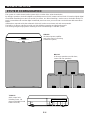 8
8
-
 9
9
-
 10
10
-
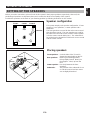 11
11
-
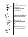 12
12
-
 13
13
-
 14
14
-
 15
15
-
 16
16
-
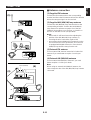 17
17
-
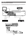 18
18
-
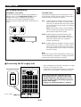 19
19
-
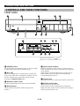 20
20
-
 21
21
-
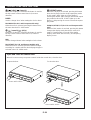 22
22
-
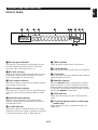 23
23
-
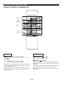 24
24
-
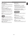 25
25
-
 26
26
-
 27
27
-
 28
28
-
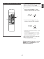 29
29
-
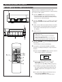 30
30
-
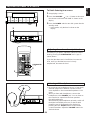 31
31
-
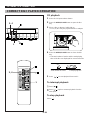 32
32
-
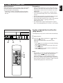 33
33
-
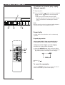 34
34
-
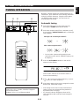 35
35
-
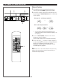 36
36
-
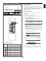 37
37
-
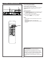 38
38
-
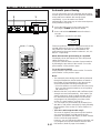 39
39
-
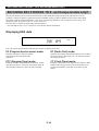 40
40
-
 41
41
-
 42
42
-
 43
43
-
 44
44
-
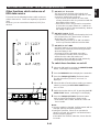 45
45
-
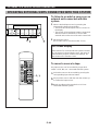 46
46
-
 47
47
-
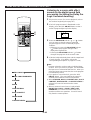 48
48
-
 49
49
-
 50
50
-
 51
51
-
 52
52
-
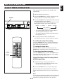 53
53
-
 54
54
-
 55
55
-
 56
56
-
 57
57


Yamaha av 1 cine station Manual de usuario
- Categoría
- Reproductores de CD
- Tipo
- Manual de usuario
en otros idiomas
- français: Yamaha av 1 cine station Manuel utilisateur
- italiano: Yamaha av 1 cine station Manuale utente
- English: Yamaha av 1 cine station User manual
- Deutsch: Yamaha av 1 cine station Benutzerhandbuch
- русский: Yamaha av 1 cine station Руководство пользователя
- Nederlands: Yamaha av 1 cine station Handleiding
- português: Yamaha av 1 cine station Manual do usuário
- dansk: Yamaha av 1 cine station Brugermanual
- polski: Yamaha av 1 cine station Instrukcja obsługi
- čeština: Yamaha av 1 cine station Uživatelský manuál
- svenska: Yamaha av 1 cine station Användarmanual
- Türkçe: Yamaha av 1 cine station Kullanım kılavuzu
- suomi: Yamaha av 1 cine station Ohjekirja
- română: Yamaha av 1 cine station Manual de utilizare
Artículos relacionados
-
Yamaha AV-S7 El manual del propietario
-
-
-
-
-
-
-
-