Minka-Aire F745-BN Instrucciones de operación
- Categoría
- Ventiladores domésticos
- Tipo
- Instrucciones de operación

CERTIFICATE
Sabot

Manual design and all elements of manual design are protected by U.S. Federal and/or State Law, including Patent, Trademark and/or Copyright laws.

The Minka-Aire® warranty is for one (1) year from the date of purchase from an authorized Minka-Aire® dealer.
This warranty is only valid to the original purchaser or user against all defects in material and workmanship light bulbs (
excluded for one full year. Additionally, Minka-Aire® warrants the motor only for the lifetime of the Minka Aire ceiling ) (1)
fan excluding wall controls and electrical components , to the original purchaser or user. ( )
* The warranty is voided with the use of any non- Minka-Aire®electrical devices, e.g., wall controls or electrical dimmer switches, etc…
* The warranty is void once the original purchaser or user ceases to own the fan or the fan is moved from its original point of installation.
* The warranty is void with the use of any hanger bracket (non-Minka Aire or non-fan specific other than the hanger bracket supplied )
& installed
with this specific fan.

Date Purchased Store Purchased Model Number Serial Number
F745
Warranty Service Information
To obtain warranty service during the warranty period, the purchaser should return the fan with the sales receipt to the original place of
purchase. The authorized Minka-Aire® dealer, at its sole discretion, will either repair or replace the fan after verifying the legitimacy of the warranty
claim. Replacement is subject to availability of the same model. If the model is unavailable it will be replaced by one of equal value. This is a limited
warranty; the original purchaser or user is responsible for the cost of removal and reinstallation of repaired or replacement product.
To obtain the name of the Minka-Aire® authorized dealer nearest you call the Minka-Aire® customer care department at 1-800-307-3267, or
contact Minka-Aire® through www.minkagroup.net and select FAQ to answer any questions or if you require additional assistance submit the question
form found there.

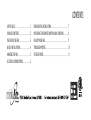
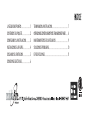
CONTENTS
FINISHING THE INSTALLATION
OPERATING THE REMOTE CONTROL/WALL CONTROL
CARE OF YOUR FAN
TROUBLESHOOTING
SPECIFICATIONS
SAFETY RULES
PACKAGE CONTENTS
INSTALLING THE FAN
BLADE INSTALLATION
HANGING THE FAN
ELECTRICAL CONNECTIONS
1
2
3
4
5
6
7
8
9
10
11
........................................................
...............
...............................................................................
...........................................................................
...................................................................................
...................................................
......................................
......................................
...................................
..........................................
..........................

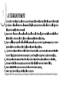
SAFETY RULES
1
1.
2. Be cautious! Read all instructions and safety information before installing your new fan. Review accompanying assembly diagrams.
3. Make sure that all electrical connections comply with local codes, ordinance, or National Electrical Codes. Hire a qualified electrician or
consult a do-it-yourself wiring handbook if you are unfamiliar with installing electrical wiring.
4. Make sure the installation site you choose allows the fan blades to rotate without any obstructions. Allow a minimum clearance of 7 feet
from the floor and 18 inches from the top of the blades to the wall.
5. If you are mounting the fan to a ceiling fan outlet box, use a U.L Listed metal octagonal outlet box marked"Acceptable For Fan Support".
Secure the box directly to the building structure. The outlet box and its support must be able to support the moving weight of the fan (at
least 50 pounds). Do not use a plastic box.
6. Caution: To reduce the risk of injury use only the screws provided with the outlet box in conjunction with the lock washers provided with
the fan.
7. If you are mounting the fan to a joist, make sure it is able to support the moving weight of the fan (at least 50 pounds).
8. After you install the fan, make sure that all mounting components are secured to prevent the fan from falling.
9. Do not insert anything into the fan blades while the fan is operating.
10. Turn the fan off and wait for the blades to stop completely before performing any maintenance or cleaning.
Before you begin installing the fan, shut power off the circuit breaker of the fuse box.

NOTE: The important safeguards and instructions appearing in this manual are not meant to cover all possible conditions and
situations that may occur. It must be understood that common sense, caution and care are factors which cannot be built into
this product. These factors must be supplied by the person(s) installing, caring for and operating the unit.
NOTE: READ AND SAVE ALL INSTRUCTIONS!
WARNING
TO REDUCE THE RISK OF FIRE,ELECTRIC SHOCK OR OTHER PERSONAL INJURY, MOUNT FAN ONLY TO A U.L LISTED OUTLET BOX OR SUPPORTING
SYSTEM MARKED ACCEPTABLE FOR FAN SUPPORT AND USE MOUNTING SCREWS PROVIDED WITH THE OUTLET BOX IN CONJUCTION WITH THE
LOCK WASHERS PROVIDED WITH THE FAN. MOST OUTLET BOXS COMMONLY USED FOR THE SUPPORT OF LIGHTING FIXTURES ARE NOT
ACCEPTABLE FOR FAN SUPPORT AND NEED TO BE REPLACED. CONSULT A QUALIFIDE ELECTRICIAN IF IN DOUBT.
TO REDUCE THE RISK OF PERSONAL INJURY, DO NOT BEND THE BLADE HOLDERS WHILE INSTALLING BALANCING THE BLADES OR CLEANING
THE FAN. DO NOT INSERT FOREIGN OBJECTS BETWEEN ROTATING FAN BLADES.
TO REDUCE THE RISK OF FIRE OR ELECTRONIC SHOCK, THIS FAN ONLY CAN USE DL-4510 REMOTE CONTROL ONLY.
ATTENTION: The Energy Policy Act of 2005 requires this fan to be equipped with a 190 watt limiting device, If lamping exceeds
190watts, the ceiling fan’s light kit will shut off automatically.

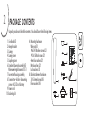
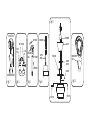
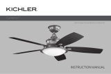
PACKAGE CONTENTS
1. Fan blades(5)
2. Hanger bracket
3. Canopy
4. Canopy cover
5. Coupling cover
6. Standard downrod assembly(6")
Minimum-length downrod(3.5")
7. Fan motor/housing assembly
8. Transmitter + holder + 2mounting
screws + A23 12 volt battery
9. Power cord
10. Balancing kit
A
A. Mounting hardware:
Wire nuts(3)
#8x3/4”Machine screws (2)
#10x1.5Wood screws (2)
4mm Star washers (2)
Metal washers (2)
Lock washers (2)
B. Blade attachment hardware:
3/16“x8mm Screws(16)
Fiber washers (16)
2
Unpack your fan and check the contents. You should have the following items:
1
2
3
4
5
6
7
8
B
10
9

3
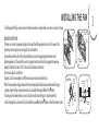
INSTALLING THE FAN
MOUNTING OPTIONS
If there isn't an existing mounting box, then read the following instructions. Disconnect the
power by removing fuses or turning off circuit breakers.
Secure the outlet box directly to the building structure. Use appropriate fasteners and
building materials. The outlet box and its support must be able to fully support the moving
weight of the fan (at least 50 lbs.).Use a UL listed metal outlet box.
Do not use a plastic outlet box.
Figure1,2 and 3 are examples of different ways to mount the outlet box.
Note: You may need a longer downrod to maintain proper blade clearance when installing on
R
a steep, sloped ceiling. Longer downrods are available from your Minka-Aire dealer.
To hang your fan where there is an existing fixture but no ceiling joist, you may need to
R
install a hanger bar as shown in Fig.4(available at your Minka Aire dealer or local hardware store)
Tools Required: Philips screw driver, slotted screw driver, step-ladder, wire cutters, electrical tape.
FIG. 1
CROSS BRACE
CEILING
JOIST
CEILING
jOIST
OUTLET
BOX
FIG. 2
PARALLEL
WOOD BRACE
(MIN. 2’’ THICK)
OUTLET
BOX
CEILING
JOIST OR
CROSS BRACE
FIG. 3
ANGLED CEILING
MAXIMUM 18°ANGLE
PROVIDE
STRONG
SUPPORT
RECESSED
OUTLET
BOX
HANGER
OPENING
must be
FACING
UPSIDE
FIG. 4
CEILING
JOIST
OUTLET BOX
HANGER BAR
(OPTIONAL)
HANGER
BRACKET

4
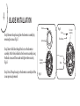
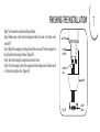
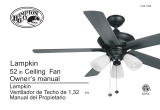
BLADE INSTALLATION
Step 1.
removing five screws.(Fig.5)
Step 2.Insert the blades through the slots on the fan motor
assembly. Attach the fan blades to the fan motor assembly using
the blade screws and fiber washer and tighten them securely.
(Fig. 6)
Step 3. Install the up housing to the fan motor assembly with the
screws previously removed.
Remove the up housing from the fan motor assembly by
Blade
Fiber Washer
Screw
Fig. 5
Fig. 6
Screws
Up housing
Fan motor
assembly
Fan motor
assembly

5
HANGING THE FAN
WARNING: All of the parts, hardware and components such as the
hanger bracket and hanger ball have been provided for your safety and
the proper installation of your new ceiling fan. The use of other
R
parts,hardware or components not supplied by Minka Aire with the fan
R
will void the Minka Aire Warranty.
REMEMBER to turn off the power. Follow the steps below to hang your
fan properly:
Step 2.Lossen the two set screws and remove the hitch pin and lock pin
from the top coupling of the motor assembly.(Fig 8)
Step 3.Remove hanger ball from downrod assembly by loosening set
screw,removing the cross pin, and sliding ball off rod.(Fig 9)
Step 1.Secure the hanger bracket to the ceiling outlet box using screws
and washers included with mounting hardware.(Fig.7)
Step 4.Carefully feed fan wires up through the downrod(Fig 10).
Thread the rod into the coupling, next line up holes and replace lock
pin and hitch pin. Tighten set screws.
Step 6. Now lift motor assembly into position and place hanger ball
into hanger bracket. Rotate until the check groove has dropped into
the registration slot and seats firmly.(Fig 12)Rod should not rotate
if this is done correctly.
Step5.Slip coupling cover, canopy cover, and canopy onto downrod
(Fig.11).Carefully reinstall hanger ball onto rod being sure that cross
pin is in the correct position, set screws are tighten and wires are
not twisted.

Fig. 12
REGISTRATION
SLOT
Fig. 10
DOWNROD
SUPPLY
WIRES
Fig. 9
CROSS PIN
HANGER
BALL
DOWNROD
SET SCREW
Fig. 8
HITCH
PIN
LOCK
PIN
SET SCREWS
Fig. 7
OUTLET BOX
HANGER BRACKET
Fig. 11
LOCK PIN
CANOPY
COVER
DOWNROD
CANOPY
SCREWS
HITCH PIN
COUPLING

6
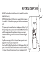
ELECTRICAL CONNECTIONS
WARNING: To avoid possible electrical shock be sure electricity is turned off at the main fuse or
breaker box before wiring.
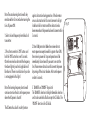
NOTE: The Aire Control® System for this DC motor fans is equipped with a learning frequency
function which has 32 code combinations to prevent potential interference from other remote
units.
The frequency on your Receiver and Transmitter units have been preset at the factory. (Fig. 13)
No frequency change is necessary, should you desire to install another Minka Aire DC motor fan
within the same home or area with a separate frequency code please see the "frequency
interference" troubleshooting section of this instruction manual to learn how to change the
frequency.
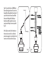
Step 1. Motor to House Supply Wires Electrical Connections: Firmly snap the wire connection
plugs from the motor and the power cord together. (Fig. 14)
Connect the WHITE wire (Neutral) from the outlet box to the WHITE wire marked "AC in N" in the
power cord. Connect the BLACK wire (Hot) from the outlet box to the BLACK wire marked "AC in
L" in the power cord. Secure all wire connections with the plastic wire nuts provided. (Fig. 15)
Fig. 13

Step 2. If your outlet box has a GROUND wire
(Green or Bare Copper) connect this wire to the
Hanger Ball and Hanger Bracket Ground wires. If
your outlet box does not have a Ground Wire,
then connect the Hanger Ball and Hanger
Bracket Ground Wires together. Secure wire
connection with the plastic wire nut provided.
(Fig. 15)
After all splices are made, check to make sure
there are no loose strands. As an additional
precaution we suggest to secure the plastic wire
connectors to the wires with electrical tape.
Fig. 15
Connection plug
Power cord
Fig. 14

7
FINISHING THE INSTALLATION
Fig. 16
OUTLET BOX
HANGER
BRACKET
HANGER
BALL
CANOPY
CANOPY
COVER
″
Step 1. Tuck connections neatly into ceiling outlet box.
Step 2. Remove one screw from the hanger bracket and loosen the other screw
around 1/4” .
Step 3. Align the canopy up to ceiling and over the loose screw. Place the canopy into
key hole and rotate canopy clockwise. (Figure 16)
Step 4. Secure the canopy by use previous removed screw.
Step 5. Place the canopy cover to the canopy and rotate canopy cover clockwise until
it is locked into right position. (Figure 16)

8
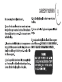
OPERATING THE REMOTE CONTROL/WALL CONTROL
cool

Note: The auto learning function will only
mandate within 60 seconds when turning the
fan’s AC power ON.
1. Select desired frequency from the back of
transmitter.
2. Press the transmitter’s “Off” button, and
hold the “Off” button for over 10 seconds.
Once the receiver has detected the frequency,
the down light of your fan if applicable will
blink twice. (There is no indication if your fan
is not equipped with a light).
Note: The learning frequency function will
continue to retain the last set frequency even
when the AC power is shut off.
The DC motor has a built in safety feature
against obstruction during operation, if the fan motor
senses a obstruction for 60 seconds or more it will get
locked and will not rotate until the obstruction has
been removed and the power has been disconnected for
5 seconds.
2. Over 60W protection: When the receiver detects
motor power consumption which is greater than 60W,
the receiver’s power will stop and operation will be
immediately discontinued. If you want to re-start the
fan, Please remove obstacles and disconnect the power
by turning off the circuit breaker . And turn the power
on after 5 seconds.
3. “DIMMER” and “ON/OFF” dip switch:
The “DIMMER” selection is the light dimmable selection
and is to be used with all bulbs except for CFL bulbs. The
“ON/OFF” selection is For CFL bulbs.
Fig. 17

Fig. 19Fig. 18
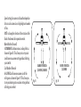
Speed settings for warm or cold weather depend on
factors such as room size, ceiling height and number
of fans.
NOTE: to change the direction of the rotation of the
blades the fan must be in operation mode.
Warm Weather (forward)
A DOWNWARD airflow creates a cooling effect as
shown in Figure 18. This allows you to set your air
conditioner on a warmer setting without affecting
your comfort.
Cool Weather (Reverse)
An UPWARD airflow moves warmer air off the
ceiling area as shown in Figure 19. This allows you
to set your heating unit on a cooler setting without
affecting your comfort.
SUMMER OPERATION
COUNTER CLOCKWISE
WINTER OPERATION
CLOCKWISE

9
CARE OF YOUR FAN

SYMPTOM
Fan will not start
SOLUTION
Check to make sure the wall switch is turned on.
Check circuit fuses or breakers.
Caution! Make sure the power is turned off before performing the
following steps.
Remove canopy and check wire connections.
Check wall control transmitter connections(if applicable).
Note: Fan must be installed at a maximum distance of 40 feet from
the transmitting unit for proper signal transmission between the
transmitting unit and the fan’s receiving unit.
SYMPTOM
Fan Sounds Noisy
SOLUTION
Allow a 24 - hour “ break in ” period. Most noises associated
with a new fan will go away during this time.
Make sure the screws that attach the fan blade holder to the
motor hub is tight.
Make sure outlet box is secured to building structure, if
necessary use the wood screws provided to further secure
outlet box to joist.
Make sure hanger bracket is secure to the outlet box, screws are
tight.
10
TROUBLESHOOTING

SYMPTOM
Fan Wobble
SOLUTION
NOTE: All blade sets are grouped by weight. Because wood and plastic
blades vary in density, the fan may wobble even though blades are
matched.
Make sure outlet box is secured to building structure, if necessary use
the wood screws provided to further secure outlet box to joist.
Make sure hanger bracket is secure to the outlet box, screws are tight.
If a Balancing kit is provided follow the instructions included with the
balancing kit to help correct any excessive wobble.
SYMPTOM
Lights shut off and will not come back on
SOLUTION
This unit is equipped with a wattage limiting device. Lamping in
excess of 190 watts will disable your ceiling fan’s light kit. To reset
your light kit you must turn the power off and re lamp, keeping the
wattage under 190 watts.
SYMPTOM
Fans/Light Turn on and Off Unexpectedly
SOLUTION
This is caused by interference. Please see “frequency interference” for
step to charge the frequency.

SYMPTOM
Frequency Interference
SOLUTION
1.Turn the power off to your ceiling fan.
2.Please use a small size tool to change the frequency settings on the control system.
3.Returm power to the unit.
Note: After the AC power is on, do not press any other button on the transmitter before pressing the “Stop” button, doing so will cause the procedure to fail.
4.Within 60 seconds of turning the fan’s AC power ON. Press the transmitter’s “Stop” button and hold the “Stop” button for 10 seconds.
5.Once the receiver has detected the set frequency, the down light of your fan if applicable will blink twice.(there is no indication if your fan is not equipped
with a light).
6.The receiver has now learn the frequency which has been selected on the transmitter. After completing the steps above, you should be able to operate the
ceiling fan and light. If the fan is not responding to the transmitter. please turn the power off to the receiver, and repeat the process.

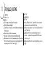
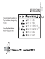
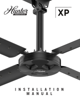
SPECIFICATIONS
These are typical readings. Your actual fan may vary.
They do not include amps and wattage used by
the light (s).
R
For any additional information about your
Minka Aire Ceiling fan, please write to:
R
11
52"
0.043
0.07
0.11
0.18
0.27
0.42
2.7
4.6
7.6
12.7
20.0
33.0
50
74
98
122
145
173
1635
2566
3396
4221
4918
5779
5.72
kgs
6.66
kgs
1.175’

1635
2566
3396
4221
4918
5779
2.7
4.6
7.6
12.7
20.0
33.0
606
558
447
332
246
175

Sabot
MANUAL DE INSTRUCCIONES CERTIFICADO DE GARANTIA

Diseño del manual y todos los elementos del diseño de manual están protegidos por EE.UU. y / o federales del Estado de Derecho, incluyendo
patentes, marcas y / o derechos de autor.

La garantía de Minka-Aire® es de un año a partir de la fecha de compra de un distribuidor autorizado de (1)
Minka-Aire®. Esta garant a sólo es válida para el comprador original o al usuario contra cualquier defecto de material y í
mano de obra focos no incluidos por año completo. Adem s, Minka-Aire® garantiza por vida el motor del ventilador ( ) (1) á
de techo únicamente por vida con exclusi n de los controles de la pared y componentes el ctricos , al comprador ( ó é )
original o al usuario.
* La garant a queda anulada con el uso de los equipos el ctricos que no son de Minka-Aire®, controles de ejemplo, interruptoresí é de pared o
interruptores eléctricos regulador, etc ...
* La garant a no es v lida una vez que el comprador original o el usuario deja de poseer el ventilador o el ventilador se mueveí á
desde su punto de
instalaci n original. ó
* La garant a es vac a con demandar de cualquier soporte de suspensi n (non-Minka Aire o no abanico espec fico) adem s del sopoí í ó í á
rte de suspensi n ó
suministrado e instalado con este abanico especificamente.

Fecha de Compra Tienda Donde Lo Compro Num. De Modelo Num. De Serie
F745
Para obtener servicio de garant a durante el per odo de garant a, el comprador debe devolver el ventilador con el recií í í bo de compra al lugar
original de compra. El distribuidor autorizado de Minka-Aire®, a su discreci n, puede reparar o reemplazar el ventilador despuó és de verificar la
legitimidad de la reclamaci n de garant a. Reemplazo est sujeto a la disponibilidad del mismo modelo. Si el modelo no est disó í á á
ponible ser , á
sustituido por uno de igual valor. Esta es de una garant a limitada, el comprador original o usuario es responsable por el costí o de quitar y reinstalar
del producto reparado o reemplazado.
Informaci n de Servicio de Garant aó í
Para obtener el nombre del distribuidor Minka-Aire® autorizado m s cercano se llama a Minka-Aire® departamento de atená
ci n al cliente al ó
1-800-307-3267, ó é o p ngase en contacto Minka-Aire® a trav s de www.minkagroup.net y seleccione FAQ para responder a cualquier pregunta, o si
necesita ayuda adicional, envie el formulario de preguntas que encontró alli.

LA SEGURIDAD PRIMERO
CONTENIDO DEL PAQUETE
COMENZANDO LA INSTALACION
INSTALACION DE LAS ASPAS
COLGANDO EL VENTILADOR
CONEXIONES ELECTRICAS
1
2
3
4
5
6
7
8
9
10
11
.....................................................
OPERACION DEL CONTROL REMOTO O EL TRANSMISOR DE PARED
......
MANTENIMIENTO DE SU VENTILADOR
.........................................
SOLUCION DE PROBLEMAS
...............................................................
ESPECIFICACIONES
.............................................................................
...............................
...........................
...............
........................
........................
.............................
TERMINANDO LA INSTALACION

1
10.Apague el ventilador y espere a que las aspas se detengan por completo antes de realizar cualquier tarea de mantenimiento o limpieza.

PARA REDUCIR EL RIESGO DE INCENDIO O DESCARGA ELÉCTRICA, ESTE VENTILADOR SÓLO SE PUEDE UTILIZAR DL-4510 CONTROL
REMOTO SOLAMENTE.

2
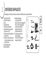
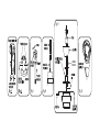
CONTENIDOS EN PAQUETE
Desempaquete su ventilador y verifique los contenidos. Usted debe tener los siguientes elementos:
1. Aspa de ventilador
(
5)
2. Soporte de suspensión
3. Dosel
4. Cubierta de dosel
5. Cubierta de acoplamiento
6. Asamblea de barra estándar (6 ")
Barra más corta (3.5 ")
7. Motor de ventilador/asamblea de
caja protectora
8. Transmisor con portatransmisores
+ 2 tornillos de montaje + bateria
A23 de 12 voltios
9. Cable de alimentación
10.Juego de Equilibrio
A. Hardware de montaje:
Tuercas de alambre (3)
#8x3/4” Tornillos de la máquina (2)
#10x1.5 Tornillos de madera (2)
Arandelas de seguridad (2)
Arandelas de estrella (2)
Arandelas de metálica (2)
B. Hardware para montaje de
accesorios de aspa:
Tornillos de 3/16“x8mm (16)
Arandelas de fibra (16)
A
1
2
3
4
5
6
7
8
B
10
9

3
18

4
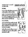
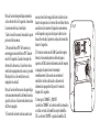
INSTALACIÓN DE LAS ASPAS
Paso 1.
quitando los cinco tornillos.(Fig.5)
Paso 2.Inserte las aspas a través de las ranuras encima del conjunto
del motor del ventilador. Fije las hojas del ventilador en el
conjunto del motor del ventilador por utilizando los tornillos de
aspa y la arandela de fibra, entonces los aprieten fuertemente.
(Fig. 6)
Paso 3. Reinstale la carcasa
Quite la carcasa de la unidad del motor del ventilador
.
Fig. 5
Fig. 6
CARCASA
CONJUNTO DEL MOTOR
DEL VENTILADOR
ASPA
TORNILLOS
ARANDELAS
DE FIBRA
TORNILLOS
CONJUNTO DEL MOTOR
DEL VENTILADOR

5

CUBIERTA
DE DOSEL
Fig. 9 Fig. 10
Fig. 11
Fig. 12

6
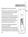
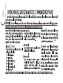
CONEXIONES ELECTRICAS
RECORDAR: Apagar la energia electrica en el circuito principal o en la caja de fusibles.
NOTA: El Control de Aire® para los ventiladoeres de motor de corriente directa está equipado
con una función de aprendizaje de frecuencia que tiene 32 combinaciones de códigos para
evitar la posible interferencia de otras unidades de control remoto.
La frecuencia de su receptor y transmisor de las unidades han sido ajustados en la fábrica. (Fig.
13) No cambio de frecuencia es necesario, si usted desea instalar otro Minka Aire ventilador con
motor de corrienta directa dentro de la misma casa o en la misma área con un código de
frecuencia diferent por favor consulte la "interferencia de frecuencia" sección de solución de
problemas de este manual de instrucciones para aprender a cambiar la frecuencia.
Paso 1. Haga las conexiones de la caja de distribucion a el Receptor de la manera siguiente;
Se encajan las clavijas de conexión de cables.(Fig.14)
Conecte el Alambre blanco (neutral) de la caja de distribucion al alambre blanco marcado "AC in
N" del receptor. Conecte el Alambre Negro (corriente) de la caja de distribucion al alambre Negro
marcado "AC in L" del Receptor. Asegure las conexiones con los conectores de plastico proveidos.
(Fig. 15)
FRECUENCIA
Fig. 13

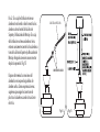
Paso 2. Si su caja de distribucion tiene un
alambre a tierra (verde o cobre) conectelo a los
alambres a tierra (verdes) de la Esfera de
Soporte y la Abrazadera de Montaje. Si su caja
de distribucion no tiene un alambre a tierra,
entonces unicamente conecte los dos alambres a
tierra de la Esfera de Soporte y la Abrazadera de
Montaje. Asegure la conexion con un conector
de plastico proveido. (Fig. 15)
Despues de terminar las conexiones del
alambrado, revise que no haiga hebras de
alambre sueltas. Como una precaucion mas,
sugerimos que asegure los conectores de
plastico a los alambres usando cinta aislante
electrica.
CONEXIÓN DE CABLES
CABLE DE ALIMENTACIÓN
Fig. 14 Fig. 15

7
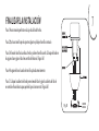
FINALIZAR LA INSTALACIÓN
Paso 1. Hace conexión perfecta en la caja de salida del techo.
Paso 2. Quita un tornillo por el soporte colgante y afloje el tornillo contrario.
Paso 3. Alinea el dosel hacia arriba al techo,y sobre el tornillo suelto. Coloque el dosel en
el agujero clave y gira el dosel en sentido del horario. (Figura 16)
Paso 4. Asegúre el dosel usando el tornillo quitado anteriormente.
Paso 5. Coloque la cubierta de dosel por encima del dosel y girar la cubierta del dosel
en sentido el horario hasta que quede el la posición correcta. (Figura 16)
Fig. 16
CUBIERTA
DE DOSEL

8

Nota: La función de aprendizaje automático
sólo es dentro de los 60 segundos al encender
la corriente electrica al ventilador .
1. Seleccione la frecuencia deseada en la parte
posterior del transmisor.
2. Presione el botón "Off" del transmisor, y
mantenga presionado el botón "Off" durante
más de 10 segundos. Cuando el receptor ha
detectado la frecuencia, la luz inferior de su
ventilador se parpadeará dos veces si procede.
(No hay indicios si el ventilador no está
equipado con una luz).
Nota: La función de frecuencia de aprendizaje
continuará manteniendo la última frecuencia
ajustada, incluso si la fuente de alimentación
de CA está apagada.
1. El motor de corriente continua cuenta con
una caracteristica de seguridad contra la
durante la operación, si el motor del ventilador detecta
una obstrucción durante 60 segundos como mínimo,
será bloqueado y no girará hasta que la obstrucción
haya sido retirada y la potencia se haya desconectado
durante 5 segundos.
2. Protección contra más de 60W: Cuando el receptor
detecta el consumo de potencia del motor que es
superior a 60 W, la fuente de alimentación del receptor
se apagará y la operación se interrumpirá
inmediatamente. Si desea volver a encender el
ventilador, retire los obstáculos y desconecte la
alimentación apagando el disyuntor. Y encienda
después de 5 segundos.
3. Interruptor “DIMMER” y “ON/OFF”:
La selección “DIMMER” es la selección de luz atenuada y
se utiliza con todas las bombillas excepto bombillas
CFL. La selección “ON/OFF” es para las bombillas CFL.
obstrucción
Fig. 17

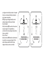
Fig. 19Fig. 18
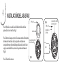
La configuración de velocidad de aire caliente o frío depende
de factores como el tamaño de la habitación, la altura de
techo y el número de ventiladores.
NOTA: Espere a que se detengan el ventilador antes de
cambiar la configuración del interruptor deslizante.
Aire cálido (adelante)
Un flujo de aire hacia ABAJO crea un efecto refrescante como
se muestra en Figura 18. Eso le permite definir su
acondicionador de aire en una configuración más cálida sin
afectar a su comodidad.
Aire fresco (Reverso)
Un flujo de aire hacia ARRIBA mueve el aire caliente fuera de
la zona de techo como se muestra en la Figura 19. Esto le
permite configurar su unidad de calefacción en una
configuración más fría, sin afectar su comodidad.
OPERACIÓN EN VERANO
SENTIDO ANTIHORARIO
OPERACIÓN EN INVIERNO
SENTIDO HORARIO

9

10


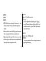
ESPECIFICACIONES
11
52"
0.043
0.07
0.11
0.18
0.27
0.42
2.7
4.6
7.6
12.7
20.0
33.0
50
74
98
122
145
173
1635
2566
3396
4221
4918
5779
5.72
kgs
6.66
kgs
1.175’

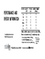
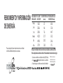
RENDIMIENTO Y INFORMACIÓN
DE ENERGÍA
Para cualquier información adcional sobre su ventilador
de Techo de Minka Aire por favor escriba a:
VELOCIDAD DE
VENTILADOR
FLUJO DE
AIRE(CFM)*
USO DE POTENCIA
(vatios)
EFICIENCIA DE FLUJO
DE AIRE(CFM/vatio)
Baja
2nd
3rd
Media
5th
Alta
El flujo de ventilador de techo se mide en pies cúbicos por minuto(CFM).
El uso de potencia se mide en vatios. Para maximizar los ahorros de energía:
Seleccione un ventilador con alta eficiencia de flujo(CFM/vatio).
Use -etiquetada iluminando en su ventilador.
Recuerde a apagar su ventilador cuando sala de la habitación
*
el método de ensayo de
Estado Sólido aprobado
por
Medido de acuerdo con
1635
2566
3396
4221
4918
5779
2.7
4.6
7.6
12.7
20.0
33.0
606
558
447
332
246
175
-
 1
1
-
 2
2
-
 3
3
-
 4
4
-
 5
5
-
 6
6
-
 7
7
-
 8
8
-
 9
9
-
 10
10
-
 11
11
-
 12
12
-
 13
13
-
 14
14
-
 15
15
-
 16
16
-
 17
17
-
 18
18
-
 19
19
-
 20
20
-
 21
21
-
 22
22
-
 23
23
-
 24
24
-
 25
25
-
 26
26
-
 27
27
-
 28
28
-
 29
29
-
 30
30
-
 31
31
-
 32
32
-
 33
33
-
 34
34
-
 35
35
-
 36
36
-
 37
37
-
 38
38
-
 39
39
-
 40
40
-
 41
41
-
 42
42
-
 43
43
-
 44
44
-
 45
45
-
 46
46
-
 47
47
-
 48
48


Minka-Aire F745-BN Instrucciones de operación
- Categoría
- Ventiladores domésticos
- Tipo
- Instrucciones de operación
En otros idiomas
Documentos relacionados
-
Minka-Aire F556-ORB Instrucciones de operación
-
Minka-Aire F533-BN Manual de usuario
-
Minka-Aire F563-WH Manual de usuario
-
Minka Group F888L-BNW Manual de usuario
-
Minka Group WCS223 Manual de usuario
-
-
Minka Group F546-WH Manual de usuario
-
Otros documentos
-
 Aire a Minka Group Design 04661 Instrucciones de operación
-
 Hinkley 903752 52 Inch Chisel Ceiling Fan Manual de usuario
-
none CL11012 Guía de instalación
-
 Kichler Lighting 310204WCP Manual de usuario
-
-
 Hampton Bay 13431103003200 Guía de instalación
-
 Hunter Fan 72123 El manual del propietario


