Husqvarna 917.374471 El manual del propietario
- Categoría
- Cortadoras de césped
- Tipo
- El manual del propietario
Este manual también es adecuado para

Owner's Manual
Husqvarna
ROTARY
160cc Honda Engine
Power=Propelled
21" Multi-Cut
Model No.
917.374472
.,Espa_ol, p. 20
CAUTION'.
Read and follow all
Safety Rules and Instructions
before operating this equipment
Sears, Roebuck and Co., Hoffman Estates, IL 60179
Visit our Craftsman website: www.sears.com/craftsman
U.S.A.

Safety Rules .......................................... 2-3
Warranty ................................................... 4
Product Specifications .............................. 5
Assembly / Pre-Operation ........................ 6
Operation ............................................. 7-11
Maintenance Schedule ........................... 12
Maintenance ...................................... 12-15
Service and Adjustments ................... 15-17
Storage .............................................. 17-18
Troubleshooting ................................. 18-19
Repair Parts ....................................... 38-45
IMPORTANT: This cutting machine is capable of amputating hands and feet and throwing ob-
jects, Failure to observe the following safety instructions could result in serious injury or death.
_i, Look for this symbol to point out im-
portant safety precautions. It means
CAUTION!H BECOME ALERT!H
YOUR SAFETY IS INVOLVED.
_I, WARNING: In order to prevent accidental
starting when setting up, transporting, ad-
justing or making repairs, always disconnect
spark plug wire and place wire where it cannot
come in contact with plug.
&WARNING: Engine exhaust, some of its
constituents, and certain vehicle compo-
nents contain or emit chemicals known to
the State of California to cause cancer and
birth defects or other reproductive harm.
_WARNING: Battery posts, terminals and
related accessories contain lead and lead
compounds, chemicals known to the State
of California to cause cancer and birth
defects or other reproductive harm. Wash
hands after handling.
A CAUTION: Muffler and other engine
parts become extremely
hot during operation and
remain hot after engine
has stopped. To avoid
severe burns on contact,
stay away from these areas.
I. GENERAL OPERATION
• Read, understand, and follow all
instructions on the machine and in the
manual(s) before starting. Be thoroughly
familiar with the controls and the proper
use of the machine before starting.
• Do not put hands or feet near or under
rotating parts. Keep clear of the dis-
charge opening at all times.
• Only allow responsible individuals, who
are familiar with the instructions, to
operate the machine.
• Clear the area of objects such as rocks,
toys, wire, bones, sticks, etc., which could
be picked up and thrown by blade.
• Be sure the area is clear of other people
before mowing. Stop the machine if
anyone enters the area.
• Do not operate the mower when bare-
foot or wearing open sandals. Always
wear substantial foot wear.
• Donotpull mowerbackwards unless abso-
lutely necessary. Always look down and be-
hind before and while moving backwards.
• Never direct discharged material toward
anyone. Avoid discharging material
against a wall orobstruction. Material may
richochet back toward the operator. Stop
the blade when crossing gravel surfaces.
• Do not operate the mower without prop-
er guards, plates, grass catcher or other
safety protective devices in place.
• See manufacturer's instructions for
proper operation and installation of
accessories. Only use accessories ap-
proved by the manufacturer.
• Stop the blade(s) when crossing gravel
drives, walks, or roads.
• Stop the engine (motor) whenever you
leave the equipment, before cleaning
the mower or unclogging the chute.
• Shut the engine (motor) off and wait
until the blade comes to complete stop
before removing grass catcher.
• Mow only in daylight or good artificial light.
• Do not operate the machine while under
the influence of alcohol or drugs.
• Never operate machine in wet grass.
Always be sure of your footing: keep a
firm hold on the handle; walk, never run.
• Disengage the self-propelled mech-
anism or drive clutch on mowers so
equipped before starting the engine.
• If the equipment should start to vibrate
abnormally, stop the engine (motor) and
check immediately for the cause. Vibra-
tion is generally a warning of trouble.
• Always wear safety goggles or safety glass-
eswith side shields when operating mower.
II. SLOPE OPERATION
Slopes are a major factor related to slip &
fall accidents which can result in severe
injury. All slopes require extra caution. If
2 you feel uneasy on a slope, do not mow it.

DO:
• Mowacrosstheface ofslopes: never
up and down. Exerciseextremecaution
whenchangingdirectionon slopes.
• Remove obstacles such as rocks, tree
limbs, etc.
• Watch for holes, ruts, or bumps. Tall
grass can hide obstacles.
DO NOT:
• Do not trim near drop-offs, ditches or
embankments. The operator could lose
footing or balance.
• Do not trim excessively steep slopes.
• Do not mow on wet grass. Reduced
footing could cause slipping.
III. CHILDREN
Tragic accidents can occur if the operator is
not alert to the presence of children. Children
are often attracted to the machine and the
mowing activity. Neverassume that children
will remain where you last saw them.
* Keep children out of the trimming area
and under the watchful care of another
responsible adult.
* Be alert and turn machine off if children
enter the area.
o Before and while walking backwards,
look behind and down for small children.
* Never allow children to operate machine.
* Use extra care when approaching blind
corners, shrubs, trees, or other objects
that may obscure vision.
IV. SAFE HANDLING OF GASOLINE
Use extreme care in handling gasoline.
Gasoline is extremely flammable and the
vapors are explosive.
• Extinguish all cigarettes, cigars, pipes
and other sources of ignition.
• Use only an approved container.
• Never remove gas cap or add fuel with
the engine running. Allow engine to
cool before refueling.
• Never refuel the machine indoors.
• Never store the machine or fuel contain-
er where there is an open flame, spark
or pilot light such as a water heater or
on other appliances.
• Never fill containers inside a vehicle, on
a truck or trailer bed with a plastic liner.
Always place containers on the ground
away from your vehicle before filling.
• Remove gas-powered equipment from the
truck or trailer and refuel it on the ground. If
this is not possible, then refuel such equip-
ment with a portable container, rather than
from a gasoline dispenser nozzle.
• Keep the nozzle in contact with the rim
of the fuel tank or container opening at
all times until fueling is complete. Do
not use a nozzle lock-open device.
• If fuel is spilled on clothing, change
clothing immediately.
• Never overfill fuel tank. Replace gas
cap and tighten securely.
V. GENERAL SERVICE
• Never run machine inside a closed area.
• Never make adjustments or repairs with
the engine (motor) running. Disconnect the
spark plug wire, and keep the wire away
from the plug to prevent accidental starting.
• Keep nuts and bolts, especially blade
attachment bolts, tight and keep equip-
ment in good condition.
• Never tamper with safety devices.
Check their proper operation regularly.
• Keep machine free of grass, leaves, or
other debris build-up. Clean oil or fuel spill-
age. Allow machine to cool before storing.
• Stop and inspect the equipment if you
strike an object. Repair, if necessary,
before restarting.
• Never attempt to make wheel height
adjustments while the engine is running.
• Grass catcher components are subject to
wear, damage, and deterioration, which
could expose moving parts or allow objects
to be thrown. Frequently check compo-
nents and replace with manufacturer's
recommended parts, when necessary.
• Mower blades are sharp and can cut.
Wrap the blade(s) or wear gloves, and
use extra caution when servicing them.
• Do not change the engine governor set-
ting or overspeed the engine.
• Maintain or replace safety and instruc-
tion labels, as necessary.
AWARNING: This lawn mower is equipped with an internal combustion engine and
should not be used on or near any unimproved forest-covered, brush-covered or
grass-covered land unless the engine's exhaust system is equipped with a spark
arrester meeting applicable local or state laws (if any). If a spark arrester is used, it
should be maintained in effective working order by the operator.
In the state of California the above is required by law (Section 4442 of the California Public
Resources Code). Other states may have similar laws. Federal laws apply on federal
lands. A spark arrester for the muffler is available through your nearest Husqvarna or
other authorized service center (See the REPAIR PARTS section of this manual).
3

SECTION 1: LIMITED WARRANTY
Husqvarna Forest & Garden Company ("Husqvarna")
warrants Husqvarna product to the original purchaser
to be free from defects in material and workmanship
from the date of purchase for the "Warranty Period" of
the product as set forth below:
2 YEAR NON-COMMERCIAL WARRANTY: Auto-
matic Mower, Riding lawn mowers, yard and garden
tractors, walk behind mowers, tillers, chain saws,
trimmers, brushcutters, clearing saws, snow blowers,
handheld blowers, backpack blowers, hedge trimmers,
electrical products and power-assist collection systems
for noncommercial, nonprofessional, noninstitutional o_
nonincome producing use, except as herein stated.
Emission control system components necessary to
comply with CARB-TIER-II and EPA regulations.
Husqvarna Safety Apparel carries a 90-day warranty
from the date of the customer's original purchase for
defects in material and workmanship. Normal wear,
tear or abuse is not covered under warranty. Product
must be returned to Charlotte with a warranty claim
form. All care and maintenance instructions must be
followed as stated by the manufacturer on the care
label. The fit of the protective apparel/boot is not
covered under warranty.
SECTION 2: HUSQ_VARNA'S OBLIGATIONS UNDER
THE WARRANTY
Husqvarna will repair or replace defective components
without charge for parts or labor if a component fails
because of a defect in material or workmanship during
the warranty period.
SECTION 3: ITEMS NOT COVERED BY THIS WAR-
RANTY
The following items are not covered by this warranty:
(1)Normal customer maintenance items which become
worn through normal regular use, including, but
not limited to, belts, blades, blade adapters, bulbs,
filters, guide bars, lubricants, rewind springs, saw
chain, spark plugs, starter ropes and tines;
(2) Natural discoloration of material due to ultraviolet
light;
(3) Lawn and garden attachments are covered by a
third party which gives a warranty, all claims for
warranty should be sent to the manufacturer; and
(4)Emission Control System components necessary
to which are manufactured by third party engine
manufacturer.
SECTION 4: EXCEPTIONS AND LIMITATIONS
This warranty shall be inapplicable to defects resulting
from the following:
(1)Accident, abuse, misuse, negligence and neglect,
including stale fuel, dirt, abrasives, moisture, rust,
corrosion, or any adverse reaction due to incorrect
storage or use habits;
(2) Failure to operate or maintain the unit in accor-
dance with the Owner's/Operator's manual or
instruction sheet furnished by Husqvarna;
(3) Alterations or modifications that change the
intended use of the product or affects the product's
performance, operation, safety, or durability, or
causes the product to fail to comply with any ap-
plicable laws; or:
(4)Additional damage to parts or components due to
continued use occurring after any of the above.
REPAIR OR REPLACEMENT AS PROVIDED UNDER
THIS WARRANTY IS THE EXCLUSIVE REMEDY OF
THE PURCHASER. HUSQVARNA SHALL NOT BE
LIABLE FOR ANY INCIDENTAL OR CONSEQUEN-
TIAL DAMAGES FOR BREACH OF ANY EXPRESS
OR IMPLIED WARRANTY ON THESE PRODUCTS
EXCEPT TO THE EXTENT PROHIBITED BY AP-
PLICABLE LAW. ANY IMPLIED WARRANTY OF
MERCHANTABILITY OR FITNESS FOR A PARTICU-
LAR PURPOSE ON THESE PRODUCTS IS LIMITED
IN DURATION TO THE WARRANTY PERIOD AS
DEFINED IN THE LIMITED WARRANTY STATE-
MENT. HUSQVARNA RESERVES THE RIGHT TO
CHANGE OR IMPROVE THE DESIGN OF THE
PRODUCT WITHOUT NOTICE, AND DOES NOT
ASSUME OBLIGATION TO UPDATE PREVIOUSLY
MANUFACTURED PRODUCTS.
Some states do not allow the exclusion of incidental
or consequential damages, or limitations on how long
an implied warranty lasts, so the above limitations or
exclusions may not apply to you. This warranty gives
you specific legal rights, and you may also have other
rights which vary from state to state.
SECTION 5: CUSTOMER RESPONSIBILITIES
The product must exhibit reasonable care, mainte-
nance, operation, storage and general upkeep as
written in the maintenance section of the Owner's/
Operator's manual. Should an operational problem
or failure occur, the product should not be used, but
delivered as is to an authorized Husqvarna dealer for
evaluation. Proof of purchase, as explained in section
6, rests solely with the customer.
SECTION 6: PROCEDURE TO OBTAIN WARRANTY
CONSIDERATION
It is the Owner's and Dealer's responsibility to make
certain that the Warranty Registration Card is properly
filled out and mailed to Husqvama Forest & Garden
Company. This card should be mailed within ten (10)
days from the date of purchase in order to confirm the
warranty and to facilitate post-sale service.
Proof of purchase must be presented to the authorized
Husqvarna dealer in order to obtain warranty service.
This proof must include date purchased, model num-
ber, serial number, and complete name and address of
the selling dealer.
To obtain the benefit of this warranty, the product
believed to be defective must be delivered to an
authorized Husqvarna dealer in a timely manner, no
later than thirty (30) days from date of the operational
problem or failure. The product must be delivered at
the owner's expense. Pick-up and delivery charges are
not covered by this warranty. An authorized Husqvarna
dealer can be normally located through the "Yellow
Pages" of the local telephone directory or by calling
1-800-HUSKY62 for a dealer in your area.
HUSQVARNA
7349 Statesville Road
Charlotte, NC 28269
531 83 81-23 2002
4

Serial Number:
Date of Purchase:
Gasoline Capacity / Type: 1.0 Quarts (Unleaded Regular)
Oil Capacity: 18.5 Ounces
Oil Type (API SG-SL): SAE 30 (above 32°F) or SAE 10W-30
Spark Plug (Gap: .030") NGK BPR6ES
Valve Clearance (_+0.04 mm): Intake: 0.015 mm; Exhaust: 0.020 mm
Blade Bolt Torque: 35-40 ft. Ibs.
• The model and serial numbers will be found on a decal on the rear of the lawn mower
housing. Record both serial number and date of purchase in space provided above.
These accessories were available when this lawn mower was produced, They are not
shipped with your mower. They are also available at most Husqvarna retailers and
service centers. Some of these accessories may not apply to your lawn mower.
LAWN MOWER PERFORMANCE
CLIPPING
DEFLECTORS
FOR
REAR DISCHARGE
LAWN MOWERS
GRASS CATCHERS
FOR
REAR DISCHARGE
LAWN MOWERS
STABILIZER
GAS
CANS
GRASS CATCHERS
FOR
SIDE DISCHARGE
LAWN MOWERS
LAWN MOWER MAINTENANCE
MUFFLERS
BELTS BLADES BLADE ADAPTERS
AIR FILTERS
WHEELS
SPARK PLUGS
ENGINE OIL

Read these instructions and this manual in its entirety before you attempt to assemble
or operate your new lawn mower.
IMPORTANT: This lawn mower is shipped WITHOUT OIL OR GASOLINE in the engine.
Your new lawn mower has been assembled at the factory with the exception of those
parts left unassembled for shipping purposes. All parts such as nuts, washers, bolts, etc.,
necessary to complete the assembly have been placed in the parts bag. To ensure safe
and proper operation of your lawn mower, all parts and hardware you assemble must be
tightened securely. Use the correct tools as necessary to ensure proper tightness.
TO REMOVE MOWER FROM CARTON
1. Remove loose parts included with
mower.
2. Cut down two end corners of carton
and lay end panel down flat.
3. Remove all packing materials except
padding between upper and lower
handle and padding holding operator
presence control bar to upper handle.
4. Roll lawn mower out of carton and
check carton thorougly for additional
loose parts.
HOW TO SET UP YOUR MOWER
TO UNFOLD HANDLE
iMPORTANT: Unfold handle carefully so
as not to pinch or damage control cables.
1. Raise lower handle section to operat-
ing position and squeeze the bottom
ends of lower handle towards each
other until the pin in handle can be
inserted into one of the three height
adjustment holes.
2. Remove protective padding, raise up-
per handle section into place on lower
handle and tighten both handle knobs.
3. Remove any packing material from
around control bar.
Your lawn mower handle can be adjusted
for your mowing comfort. Refer to "AD-
JUST HANDLE" in the Service and Adjust-
ments section of this manual.
Operator MOWING
presence POSITION
control bar _/,
SQUEEZE
Handle
bracket
Handle pin
TO ASSEMBLE GRASS CATCHER
1. Put grass catcher frame into grass bag
with rigid part of bag on the bottom.
Make sure the frame handle is outside
of the bag top.
2. Slip vinyl bindings over frame.
NOTE: If vinyl bindings are too stiff, hold
them in warm water for a few minutes. If
bag gets wet, let it dry before using.
UP
Upper
handle
Handle
knob
Lower handle
Vinyl Frame
bindings opening
TO INSTALL ATTACHMENTS
Your lawn mower was shipped ready to be
used as a mulcher. To convert mower to
bagging or discharging, see "TO CON-
VERT MOWER" in the Operation section
of this manual.

KNOW YOUR LAWN MOWER
READTHIS OWNER'SMANUALANDALL SAFETYRULESBEFOREOPERATING
YOUR LAWNMOWER. Comparethe illustrationswith your lawnmowertofamiliarize
yourselfwith the locationof variouscontrolsand adjustments. Save thismanualfor
future reference.
These symbols may appear on your lawn mower or in literature supplied with the
product. Learn and understand their meaning.
CAUTION ENGINE ENGINE FAST SLOW CHOKE FUEL OIL DANGER, KEEP HANDS
OR WARNING ON OFF AND FEET AWAY
Drive
control "Operator presence control bar
Starter
handle
Handle knob
Grass
Drive cover
Gasoline filler cap
Single
point height
adjuster
handle
Fuel shutoff valve
Air filter
Engine oil cap
with dipstick
Spark
plug
Muffler
Mulcher door Housing
IMPORTANT: This lawn mower is shipped WITHOUT OIL OR GASOLINE in the engine.
MEETS CPSC SAFETY REQUIREMENTS
Sears rotary walk-behind power lawn mowers conform to the safety standards of the
American National Standards Institute and the U.S. Consumer Product Safety Com-
mission. The blade turns when the engine is running.
Operator presence control bar = must
be held down to the handle to start the
engine. Release to stop the engine.
Starter handle = used for starting engine.
Mulcher door = allows conversion to
discharging or bagging operation.
Drive control lever = used to engage
power-propelled forward motion of mower.

The operation of any lawn
mowercan result in foreign
objectsthrownintotheeyes,
which can result in severe
eye damage. Always wear
safety glasses or eye shields while oper-
ating your lawn mower or performing any
adjustmentsor repairs. We recommenda
standardsafetyglassesorwidevisionsafety
maskworn over spectacles.
HOW TO USE YOUR LAWN MOWER
ENGINE SPEED
The engine speed was set at the factory
for optimum performance. Speed is not
adjustable.
DRIVE CONTROL ADJUSTMENT
Over time, the drive control system may
become "loose", resulting in decreased
speed. There is a turnbuckle on the drive
control housing to increase tension on the
drive cable. Proceed as follows:
1. Turn unit off and disconnect spark plug
wire from spark plug.
2. Rotate turnbuckle on drive control to
increase drive speed.
3. Operate mower to test drive speed.
Readjust as required.
4. If condition fails to improve after the
above steps (forward speed remains
the same), your drive belt is worn and
should be replaced.
ENGINE ZONE CONTROL
_I, CAUTION: Federal regulations require
an engine control to be installed on this
lawn mower in order to minimize the
risk of blade contact injury. Do not under
any circumstances attempt to defeat the
function of the operator control. The blade
turns when the engine is running.
• Your lawn mower is equipped with an
operator presence control bar which
requires the operator to be positioned
behind the lawn mower handle to start
and operate the lawn mower.
DRIVE CONTROL
• Self-propelling is controlled by hold-
ing the operator presence control bar
down to the handle and pulling the drive
control lever rearward to the handle.
The farther toward the handle the lever
is pulled, the faster the unit will travel.
• Forward motion will stop when either
the operator presence control bar or
drive control lever are released. To stop
forward motion without stopping engine,
release the drive control lever only. Hold
operator presence control bar down
against handle to continue mowing
without self-propelling.
NOTE: If after releasing the drive control
the mower will not roll backwards, push
the mower forward slightly to disengage
drive wheels.
Operator presence control bar
Drive control
lever
TO
ENGAGE
DRIVE
CONTROL
DRIVE
CONTROL
DISENGAGED
Adjustment
turnbuckle
TO ADJUST CUTTING HEIGHT
All four wheels are adjusted by a single
lever.
• Pull adjuster lever toward wheel. To
raise mower, move lever forward to
desired position. To lower mower, move
the lever toward the rear.
LEVER
BACKWARD
TO LOWER
MOWER
Height
adj
LEVER
FORWARD
TO RAISE
MOWER

TO CONVERT MOWER
Your lawn mower was shipped ready to be
used as a mulcher. To convert to bagging
or discharging:
REAR BAGGING
• Open rear door and remove mulcher
plug. Store mulcher plug in a safe
place.
• You can now install the grass catcher or
optional clipping deflector.
• To convert to mulching or discharging
operation, install mulcher plug into rear
discharge opening of mower.
Discharge deflector
\
I
I
Mulcher plug
SIDE DISCHARGING
• Mulcher plug must be installed into rear
discharge opening of mower.
• Open mulcher door and install dis-
charge deflector under door as shown.
• Mower is now ready for discharging
operation.
To convert to mulching or bagging
operation, discharge deflector must be
removed and mulcher door closed.
\ /
\ /
Open mulcher door
I
I
SIMPLE STEPS TO REMEMBER WHEN
CONVERTING YOUR LAWN MOWER
FOR MULCHING -
1. Rear mulcher plug installed.
2. Mulcher door closed.
FOR REAR BAGGING -
1. Rear mulcher plug removed.
2. Grass catcher installed.
3. Mulcher door closed.
FOR SIDE DISCHARGING -
1. Rear mulcher plug installed.
2. Discharge deflector installed.
_CAUTION: Do not run your lawn
mower without mulcher plug or approved
grass catcher in place. Never attempt to
operate the lawn mower with the rear door
removed or propped open.
TO EMPTY GRASS CATCHER
1. Lift up on grass catcher using the
frame handle.
2. Remove grass catcher with clippings
from under lawn mower handle.
3. Empty clippings from bag.
NOTE: Do not drag the bag when empty-
ing; it will cause unnecessary wear.

\/ /._\ Grass
(_, ,_XA':--_ catcher
'X_, "_ ""---.-_. _--._ ,) frame
BEFORE STARTING ENGINE
ADD OIL
Your lawnmower is shipped without oil in
the engine. For type and grade of oil to
use, see "ENGINE" in the Maintenance
section of this manual.
_i, CAUTION: DO NOT overfill engine with
oil, or it will smoke on startup.
1. Be sure lawnmower is level.
2. Remove oil fill cap/dipstick from oil fill
spout.
3. You recieve a container of oil with the
unit. Slowly pour the entire container
down the oil fill spout into the engine.
4. Insert and tighten oil fill cap/dipstick.
IMPORTANT:
• Check oil level before each use. Add oil
if needed. Fill to full line on dipstick.
• Change the oil after every 25 hours of
operation or each season. You may
need to change the oil more often
under dusty, dirty conditions. See "TO
CHANGE ENGINE OIL" in the Mainte-
nance section of this manual.
Oil fill cap / Gasoline
dips filler cap
ADD GASOLINE
• Fill fuel tank to bottom of tank filler neck.
Do not overfill. Use fresh, clean, regular
unleaded gasoline with a minimum of
87 octane. Do not mix oil with gasoline.
Purchase fuel in quantities that can be
used within 30 days to assure fuel fresh-
ness.
CAUTION: Wipe off any spilled oil or
fuel. Do not store, spill or use gasoline
near an open flame.
A CAUTION: Alcohol blended fuels
(called gasohol or using ethanol or metha-
nol) can attract moisture which leads to
separation and formation of acids during
storage. Acidic gas can damage the fuel
system of an engine while in storage. To
avoid engine problems, the fuel system
should be emptied before storage of 30
days or longer. Empty the gas tank, start
the engine and let it run until the fuel lines
and carburetor are empty. Use fresh fuel
next season. See Storage Instructions for
additional information. Never use engine
or carburetor cleaner products in the fuel
tank or permanent damage may occur.
TO STOP ENGINE
• To stop engine, release operator pres-
ence control bar. Wait until blade and
all moving parts have stopped and turn
fuel valve to OFF position if you do not
intend to restart the engine soon.
TO START ENGINE
NOTE: Due to protective coatings on the
engine, a small amount of smoke may be
present during the initial use of the product
and should be considered normal.
1. Be sure fuel valve is in the ON po-
sition.
2. Move choke lever to ON (1\1) position.
3. Hold operator presence control bar
down to the handle and pull starter
handle quickly. Do not allow starter
rope to snap back.
NOTE: The choke lever automatically
begins moving to the OFF position when
operator presence control bar is held
down to handle.
Upper Lowe
mark mark
10

OFF
Fuel valve lever
MOWING TIPS
_, CAUTION: Do not use de-thatcher
blade attachments on your mower. Such
attachments are hazardous, will damage
your mower and could void your warranty.
• Under certain conditions, such as very
tall grass, it may be necessary to raise
the height of cut to reduce pushing effort
and to keep from overloading the engine
and leaving clumps of grass clippings.
It may also be necessary to reduce
ground speed and/or run the lawn
mower over the area a second time.
• For extremely heavy cutting, reduce the
width of cut by overlapping previously
cut path and mow slowly.
• For better grass bagging and most cut-
ting conditions, the engine speed should
be set in the FAST position.
• Pores in cloth grass catchers can
become filled with dirt and dust with use
and catchers will collect less grass. To
prevent this, regularly hose catcher off
with water and let dry before using.
• Keep top of engine around starter clear
and clean of grass clippings and chaff.
This will help engine air flow and extend
engine life.
MULCHING MOWING TIPS
IMPORTANT: For best performance,
keep mower housing free of built-up
grass and trash, See "CLEANING" in the
Maintenance section of this manual,
• The special mulching blade will recut
the grass clippings many times and
reduce them in size so that as they fall
onto the lawn they will disperse into
the grass and not be noticed, Also, the
mulched grass will biodegrade quickly
to provide nutrients for the lawn, Always
mulch with your highest engine (blade)
speed as this will provide the best recut-
ting action of the blades,
• Avoid cutting your lawn when it is wet,
Wet grass tends to form clumps and
interferes with the mulching action. The
best time to mow your lawn is the early
afternoon. At this time the grass has
dried, yet the newly cut area will not be
exposed to direct sunlight.
• For best results, adjust the lawn mower
cutting height so that the lawn mower
cuts off only the top one-third of the
grass blades. If the lawn is overgrown it
will be necessary to raise the height of
cut to reduce pushing effort and to keep
from overloading the engine and leaving
clumps of mulched grass. For extremely
heavy grass, reduce your width of cut
by overlapping previously cut path and
mow slowly.
MAX 1/3
• Certain types of grass and grass
conditions may require that an area be
mulched a second time to completely
hide the clippings, When doing a sec-
ond cut, mow across (perpendicular) to
the first cut path,
• Change your cutting pattern from week
to week, Mow north to south one week
then change to east to west the next
week, This will help prevent matting and
graining of the lawn,
11

MAINTENANCE
SCHEDULE
Check for Loose Fasteners
_ lean / Inspect Grass Catcher *
Check Tires
_ Check Drive Wheels
¢.¢. ¢.
Clean Lawn Mower ....
M Clean under Drive Cover ***
O Check Drive Belt / Pulleys ***
_ Check / Sharpen / Replace Blade
R Lubrication
Clean and Recharge Battery **
Check Engine Oil level
I_ Change Engine Oil
N Clean Air Filter
_ Inspect Muffler
N Replace Spark Plug
I_ Replace Air Filter Paper Cartridge
Empty fuel system or add Stabilizer
BEFORE AFTER EVERY EVERY EVERY
EACH EACH 10 25 HOURS 100 BEFORE
USE USE HOURS OR SEASON HOURS STORAGE
i/s
t/
i/
i/
i/3
i/
i/
14
11_,2
14
I/
I/
* (if so equipped)
** Electric-Start mowers
*** Power-Propelled mowers
**** Use a scraper
to clean under deck
1 - Change more often if operating under a heavy load or in high outdoor temperatures.
2 - Service more often if operating in dirty or dusty conditions.
3 - Replace blades more often when mowing in sandy soil,
4- Charge 48 hours at end of season.
5 - And after each 5 hours of use.
GENERAL RECOMMENDATIONS
The warranty on this lawn mower does not
cover items that have been subjected to
operator abuse or negligence, To receive
full value from the warranty, operator must
maintain unit as instructed in this manual,
Some adjustments will need to be made
periodically to properly maintain your unit,
At least once a season, check to see if
you should make any of the adjustments
described in the Service and Adjustments
section of this manual,
• At least once a year, replace the spark
plug, clean or replace air filter element
and check blade for wear, A new spark
plug and clean/new air filter element
assure proper air-fuel mixture and help
your engine run better and last longer,
• Follow the maintenance schedule in this
manual,
BEFORE EACH USE
• Check engine oil level.
• Check for loose fasteners.
LUBRICATION
Keep unit well lubricated
(See "LUBRICATION CHART").
LUBRICATION CHART
Wheel
adjuster (on
each wheel)
I // Mulcher
I \ /) door hingepin
1" ") (_ Rear door
hinge
(_ Handle bracket mounting pins
_ Spray lubricant
See "ENGINE" in Maintenance section.
IMPORTANT: Do not oil or grease plastic
wheel bearings, Viscous lubricants will
attract dust and dirt that will shorten the life of
the self-lubricating bearings, If you feel they
must be lubricated, use only a dry, powdered
2graphite type lubricant sparingly,
1

LAWN MOWER
Always observe safety rules when per-
forming any maintenance.
TIRES
• Keep tires free of gasoline, oil, or insect
control chemicals which can harm rubber.
• Avoid stumps, stones, deep ruts, sharp
objects and other hazards that may
cause tire damage.
iMPORTANT: Blade bolt is heat treated.
If bolt needs replacing, replace only with
approved bolt shown in the Repair Parts
section of this manual.
Blade adapter Key Crankshaft
keyway
Lockwasher
Blade
DRIVE WHEELS
Check rear drive wheels each time before
you mow to be sure they move freely.
The wheels not turning freely means trash,
grass cuttings, etc. are in the drive wheel area
and must be cleaned to free drive wheels.
If necessary to clean the drive wheels, be
sure to clean both rear wheels.
BLADE CARE
For best results, blade must be kept
sharp. Replace a bent or damaged blade.
CAUTION: Use only a replacement
blade approved by the manufacturer of
your mower. Using a blade not approved
by the manufacturer of your mower is haz-
ardous, could damage your mower and
void your warranty.
TO REMOVE BLADE
1. Disconnect spark plug wire from spark
plug and place wire where it cannot
come in contact with plug.
2. Turn lawn mower on its side. Make
sure air filter and carburetor are up.
3. Use a wood block between blade and
mower housing to prevent blade from
turning when removing blade bolt.
NOTE: Protect your hands with gloves
and/or wrap blade with heavy cloth.
4. Remove blade bolt by turning counter-
clockwise.
5. Remove blade & attaching hardware
(bolt, lock washer & hardened washer).
TO REPLACE BLADE
1. Position blade on the blade adapter
aligning the two (2) holes in the blade
with the raised lugs on the adapter.
2. Be sure the trailing edge of blade (oppo-
site sharp edge) is up toward engine.
3. Install the blade bolt with the lock
washer and hardened washer into
blade adapter and crankshaft.
4. Use block of wood between blade and
lawn mower housing and tighten the
blade bolt, turning clockwise.
• The recommended tightening torque is
35-40 ft. Ibs.
Blade
bolt Hardened
washer Trailing edge Crankshaft
TO SHARPEN BLADE
NOTE: We do not recommend sharp-
ening the blade - but if you do, be sure the
blade is balanced. An unbalanced blade
will cause eventual damage to mower or
engine.
• The blade can be sharpened with a file
or on a grinding wheel. Do not attempt
to sharpen while on the mower.
• To check blade balance, drive a nail into
a beam or wall. Leave about one inch of
the straight nail exposed. Place center
hole of blade over the head of the nail.
If blade is balanced, it should remain in
a horizontal position. If either end of the
blade moves downward, sharpen the
heavy end until the blade is balanced.
GRASS CATCHER
• The grass catcher may be hosed with
water, but must be dry when used.
• Check your grass catcher often for dam-
age or deterioration. Through normal
use it will wear. If catcher needs replac-
ing, replace only with approved replace-
ment catcher shown in the Repair Parts
section of this manual. Give the lawn
mower model number when ordering.
13
GEAR CASE
• To keep your drive system working
properly, the gear case and area around
the drive should be kept clean and free
of trash build-up. Clean under the drive
cover twice a season.
• The gear case is filled with lubricant to the
proper level at the factory. The only time
the lubricant needs attention is if service
has been performed on the gear case.
• If lubricant is required, use only Texaco
Starplex Premium 1 Grease, Part No.
750369. Do not substitute.

ENGINE
Maintenance,repair,or replacementof
the emissioncontroldevicesandsystems,
whichare beingdoneat the customersex-
pense,maybe performedbyany non-road
enginerepairestablishmentor individual.
Warrantyrepairsmustbe performedby an
authorizedenginemanufacturer'sservice
outlet.
LUBRICATION
Use only high quality detergent oil rated
with API service classification SG-SL.
Select the oil's SAE viscosity grade
according to your expected operating
temperature.
SAEVISCOSITYGRADES
p[_',_j, I,
"F -20 0 30 32 40 60 80 100
°c -_o -20 -_; ; _; _0 10
TEMPERATURE RANGE ANTICIPATED BEFORE NEXT OIL CHANGE
NOTE: Multi-viscosity oils (5W30, 10W30
etc.) improve starting in cold weather, and
you should check your engine oil level fre-
quently to avoid possible engine damage
from running low on oil.
Change the oil after every 25 hours of opera-
tion or at least once a year if the lawn mower
is not used for 25 hours in one year.
Check the crankcase oil level before
starting the engine and after each five (5)
hours of continuous use. Tighten oil plug
securely each time you check the oil level.
TO CHANGE ENGINE OIL
NOTE: Before tipping lawn mower to drain
oil, empty fuel tank by running engine until
fuel tank is empty.
1. Disconnect spark plug wire from spark
plug and place wire where it cannot
come in contact with plug.
2. Remove oil fill cap/dipstick; lay aside
on a clean surface.
3. Tip lawn mower on its side as shown
and drain oil into a suitable container.
Rock lawn mower back and forth to re-
move any oil trapped inside of engine.
,
5.
6.
Wipe off any spilled oil from lawn
mower or side of engine.
Fill engine with oil. Slowly pour oil
down the oil fill spout into the engine.
Wait one minute to allow oil to settle.
Use guage on oil fill cap/dipstick for
checking level. Insert dipstick into
the tube and rest the oil fill cap on the
tube. DO NOT thread the cap into the
tube when taking reading.
Oil fill cap /
dipstick
Upper _
mark
Lower / '_
mark
7. Continue adding small amounts of
oil and rechecking the dipstick until it
reads full. DO NOT overfill, or engine
will smoke on startup.
8. Always be sure to retighten oil fill cap/
dipstick before starting engine.
9. Reconnect spark plug wire to spark
plug.
AIR FILTER
Your engine will not run properly and may
be damaged by using a dirty air filter.
Replace the air filter every 100 hours of
operation or every season, whichever oc-
curs first. Service air cleaner more often
under dusty conditions.
TO CLEAN AIR FILTER
1. Remove cover.
2. Carefully remove cartridge.
3. Clean by gently tapping on a flat sur-
face. If very dirty, replace cartridge.
Tab
Cartridge
14
Filter cover

_i_CAUTION: Petroleum solvents, such
as kerosene, are not to be used to clean
cartridge. They may cause deterioration
of the cartridge. Do not oil cartridge. Do
not use pressurized air to clean or dry
cartridge.
4. Install cartridge, then replace cover.
MUFFLER
Inspect and replace corroded muffler as it
could create a fire hazard and/or damage.
SPARK PLUG
Replace spark plug at the beginning of
each mowing season or after every 100
hours of operation, whichever occurs
first. Spark plug type and gap setting
are shown in the "PRODUCT SPECIFIC-
ATIONS" section of this manual.
CLEANING
IMPORTANT: For best performance,
keep mower housing free of built-grass
and trash. Clean the underside of your
mower after each use.
Af_,CAUTION: Disconnect spark plug wire
from spark plug and place wire where it
cannot come in contact with plug.
• Clean the underside of your lawn mower
by scraping to remove build-up of grass
and trash.
• Clean engine often to keep trash from
accumulating. A clogged engine runs
hotter and shortens engine life.
• Keep finished surfaces and wheels free
of all gasoline, oil, etc.
• We do not recommend using a garden
hose to clean lawn mower unless the
electrical system, muffler, air filter and
carburetor are covered to keep water
out. Water in engine can result in short-
ened engine life.
CLEAN UNDER DRIVE COVER
Clean under drive cover at least twice a
season. Scrape underside of cover with
putty knife or similar tool to remove any
build-up of trash or grass on underside of
drive cover.
• i, WARNING: To avoid serious injury,
before performing any service and
adjustments:
1. Release control bar and stop engine.
2. Make sure the blade and all moving
parts have completely stopped.
3. Disconnect spark plug wire from spark
plug and place wire where it cannot
come in contact with plug.
LAWN MOWER
TO ADJUST CUTTING HEIGHT
See "TO ADJUST CUTTING HEIGHT" in
the Operation section of this manual.
REAR DEFLECTOR
The rear deflector, attached between the rear
wheels ofyour mower, is provided to minimize
the possibility that objects will be thrown out
of the rear of the mower into the operator
mowing position. If the deflector becomes
damaged, it should be replaced.
TO REMOVE DRIVE BELT
1. Remove drive cover.
2. Remove spring and belt keeper.
3. Remove belt from gearcase pulley.
4. Turn lawn mower on its side with air
filter and carburetor down.
15,
5. Remove blade, engine pulley and
debris shield.
6. Remove engine pulley and belt from
debris shield.
Gearcase pulley
"Drive
cover
Spring
Belt
3er
Belt
\

TO REPLACE DRIVE BELT
1. Place new drive belt in engine pulley
and belt retainer of debris shield.
2. Route the other end of the new drive
belt through hole in housing.
3. Reinstall debris shield.
4. Return mower to upright position.
5. Install new belt on gearcase pulley.
6. Reinstall belt keeper and spring.
7. Reinstall drive cover.
NOTE: Always use factory approved belt
to assure proper fit and long life.
8. Turn lawn mower on its side with air
filter and carburetor down.
9. Reinstall blade.
Engine pulley
Drive belt
Belt
retainer
Debris shield
TO ADJUST HANDLE
The handle on your lawn mower has three
(3) height positions - adjust to height that
suits you.
• Squeeze the bottom ends of lower
handle towards each other until the pin
in handle can be inserted into one of the
three height adjustment holes.
Hi( Handle pin
ENGINE
Maintenance, repair, or replacement of
the emission control devices and systems,
which are being done at the customers ex-
pense, may be performed by any non-road
engine repair establishment or individual.
Warranty repairs must be performed by an
authorized engine manufacturer's service
outlet.
ENGINE SPEED
Your engine speed has been factory set.
Do not attempt to increase engine speed
or it may result in personal injury. If you
believe that the engine is running too fast
or too slow, take your lawn mower to a
Husqvarna or other qualified service cen-
ter for repair and adjustment.
CARBURETOR
Your carburetor is not adjustable. If your
engine does not operate properly due
to suspected carburetor problems, take
your lawn mower to a Husqvarna or other
qualified service center for repair and/or
adjustment.
IMPORTANT: Never tamper with the
engine governor, which is factory set for
proper engine speed. Overspeeding
the engine above the factory high speed
setting can be dangerous. If you think
the engine-governed high speed needs
adjusting, contact a Husqvama or other
qualified service center, which has proper
equipment and experience to make any
necessary adjustments.
SQ
Lo_
Handle
bracket
16

Immediately prepare your lawn mower for
storage at the end of the season or if the
unit will not be used for 30 days or more.
SQ
Handle pin
LAWN MOWER
When lawn mower is to be stored for a
period of time, clean it thoroughly, remove
all dirt, grease, leaves, etc. Store in a
clean, dry area.
1. Clean entire lawn mower (See
"CLEANING" in the Maintenance sec-
tion of this manual).
2. Lubricate as shown in the Maintenance
section of this manual.
3. Be sure that all nuts, bolts, screws, and
pins are securely fastened. Inspect
moving parts for damage, breakage
and wear. Replace if necessary.
4. Touch up all rusted or chipped paint
surfaces; sand lightly before painting.
HANDLE
You can fold your lawn mower handle for
storage.
1. Loosen the two (2) handle knobs on
sides of the upper handle and allow
handle to fold down to the rear.
2. Squeeze the bottom ends of lower
handle toward each other until pins in
handle clear the brackets and pivot
entire handle assembly forward and
allow it to rest on mower.
• When setting up your handle from the
storage position, you must manually
lock lower handle into mowing position.
IMPORTANT: When folding the handle
for storage or transportation, be sure to
fold the handle as shown or you may dam-
age the control cables.
Operator MOWING
presence POSITION
control bar
Upper
handle
Handle
bracket
ENGINE
FUEL SYSTEM
IMPORTANT: It is important to prevent
gum deposits from forming in essential
fuel system parts such as carburetor, fuel
filter, fuel hose, or tank during storage.
Alcohol blended fuels (called gasohol or
using ethanol or methanol) can attract
moisture which leads to separation and
formation of acids during storage. Acidic
gas can damage the fuel system of an
engine while in storage.
• Empty the fuel tank by starting the en-
gine and letting it run until the fuel lines
and carburetor are empty.
• Never use engine or carburetor cleaner
products in the fuel tank or permanent
damage may occur.
• Use fresh fuel next season.
NOTE: Fuel stabilizer is an acceptable
alternative in minimizing the formation of
fuel gum deposits during storage. Add
stabilizer to gasoline in fuel tank or stor-
age container. Always follow the mix ratio
found on stabilizer container. Run engine
at least 10 minutes after adding stabilizer
to allow the stabilizer to reach the car-
buretor. Do not empty the gas tank and
carburetor if using fuel stabilizer.
ENGINE OIL
Drain oil (with engine warm) and replace
with clean engine oil. (See "ENGINE" in
the Maintenance section of this manual),
Handle
knob
CYLINDER
1. Remove spark plug.
Lower handle 2. Pour one ounce (29 ml) of oil through
spark plug hole into cylinder.
17

3. Pull starter handle slowly a few times to
distribute oil.
4. Replace with new spark plug.
OTHER
• Do not store gasoline from one season
to another.
• Replace your gasoline can if your can
starts to rust. Rust and/or dirt in your
gasoline will cause problems.
• If possible, store your unit indoors and
cover it to protect it from dust and dirt.
• Cover your unit with a suitable protec-
tive cover that does not retain moisture.
Do not use plastic. Plastic cannot
breathe, which allows condensation to
form and will cause your unit to rust.
IMPORTANT: Never cover mower while
engine and exhaust areas are still warm.
_ILCAUTION: Never store the lawn
mower with gasoline in the tank inside a
building where fumes may reach an open
flame or spark. Allow the engine to cool
before storing in any enclosure.
TROUBLESHOOTING - See appropriate section in manual unless directed
to a Husqvarna Parts & Repair Center.
PROBLEM CAUSE
Does not start 1. Dirty air filter.
2. Out of fuel.
3. Stale fuel.
4. Water in fuel.
5. Spark plug wire disconnected.
6. Bad spark plug,
7. Loose blade or broken
blade adapter.
8. Control bar in released
position.
CORRECTION
1. Clean/replace air filter.
2. Fill fuel tank.
3. Empty fuel tank and refill tank
with fresh, clean gasoline.
4. Empty fuel tank and refill tank
with fresh, clean gasoline.
5. Connect wire to plug.
6. Replace spark plug.
7. Tighten blade bolt or
replace blade adapter.
8. Depress control bar to
handle.
18

TROUBLESHOOTING - See appropriate section in manual unless directed
to a Husqvarna Parts & Repair Center.
CAUSEPROBLEM
Does not start
(continued)
Loss of power
Poor cut =
uneven
Excessive
vibration
Starter rope
hard to pull
Grass catcher
not filling
(if so equipped)
Hard to push
Loss of drive
or slowing of
drive speed
9. Control bar defective.
10. Fuel valve lever (if so
equipped) in OFF position.
11. Weak battery (if equipped).
12. Disconnected battery
connector (if equipped).
1. Rear of mower housing or
blade dragging in grass.
2. Cutting too much grass.
3. Dirty air filter.
4. Buildup of grass, leaves,
and trash under mower.
5. Too much oil in engine.
6. Walking speed too fast.
1. Worn, bent or loose blade.
2. Wheel heights uneven.
3. Buildup of grass, leaves
and trash under mower.
1. Worn, bent or loose blade.
2. Bent engine crankshaft.
,
,
3.
4.
Engine flywheel brake is on
when control bar is released.
Bent engine crankshaft.
Blade adapter broken.
Blade dragging in grass.
1. Cutting height too low.
2. Lift on blade worn off.
3. Catcher not venting air.
1. Grass is too high or wheel
height is too low.
2. Rear of mower housing or
blade dragging in grass.
3. Grass catcher too full.
4. Handle height position not
right for you.
1. Belt wear.
2. Belt off of pulley.
3. Drive cable worn or broken.
4. "Loose" drive control system.
CORRECTION
9. Replace control bar.
10. Turn fuel valve lever
to the ON position,
11. Charge battery,
12. Connect battery to engine,
1. Raise cutting height.
2. Raise cutting height.
3. Clean/replace air filter.
4. Clean underside of mower
housing.
5. Check oil level.
6. Cut at slower walking speed.
1. Replace blade. Tighten
blade bolt,
2. Set all wheels at same
height,
3. Clean underside of
mower housing,
1. Replace blade. Tighten
blade bolt.
2. Contact a Husqvarna or other
qualified service center,
1. Depress control bar to
upper handle before
pulling the starter rope.
2. Contact a Husqvarna or other
qualified service center.
3. Replace blade adapter.
4. Move lawn mower to cut
grass or to hard surface.
1. Raise cutting height.
2. Replace blade.
3. Clean grass catcher.
1. Raise cutting height.
2. Raise rear of mower housing
one (1) setting higher.
3. Empty grass catcher.
4. Adjust handle height to suit.
1. Check/replace drive belt,
2. Check/reinstall drive belt.
3, Replace drive cable,
4. Adjust drive control,
19

Reglas de Seguridad ................................ 20-21
Garantia ......................................................... 22
Especificaciones del Producto ....................... 23
Montaje / Pre-Operaci6n ............................... 24
Operaci6n ................................................. 25-29
Mantenimiento .......................................... 30-33
Programa de Mantenimiento ......................... 30
Servicio y Adjustes ................................... 33-34
Almacenamiento ....................................... 35-36
ldentificaci6n de problemas ...................... 36-37
Partes de repuesto .................................. 38-45
IMPORTANTE: Esta maquina cortadaora es capaz de amputar las manos y los manos y los pies y
de lanzar objetos. Si no se observan las instrucciones de seguridad siguientes se pueden producir
lesiones graves o la muerte.
_lLBusque este simbolo que se_ala las precau-
ciones de seguridad de importancia. Quiere
decir - iiiATENCtONTT! iiiESTE ALERTO!!!
SU SEGURtDAD ESTA COMPROMETIDA.
,_ADVERTENClA: Siempre desconecte el alam-
bre de la bujia y p6ngalo donde no pueda entrar
en contacto con la bujia, para evitar el arranque
por accidente, durante la preparaci6n, el trans-
,_rte, el ajuste o cuando se hacen reparaciones.
ADVERTENClA: Los bornes, terminales y
accesorios relativos de la bateria contienen
plomo o compuestos de plomo, productos
quimicos conocidos en el Estado de California
como causa de cancer y defectos al nacimiento
u otros da_os reproductivos. Lavar las manos
,_spu_s de m,anipularlos.
PRECAUTION: El tubo de escape del motor,
algunos de sus constituyentes y algunos com-
ponentes del vehiculo contienen o desprenden
productos quimicos conocidos en el Estado de
California como causa de cancer y defectos al
,_imiento u otros daSos reproductivos.
RECAUClON: El silenciador y otras piezas
del motor Ilegan a sre extre- _---¢'r%_
madamente calientes durante
la operaci6n y siguen siendo
calientes despues de que el
motor haya parado. Para
evitar quemaduras severas,
permanezca lejos de estas areas.
I. OPERACION
. Antes de empezar, debe familiarizarse comple-
tamente con los controles y el uso correcto de
la maquina. Para esto, debe leer y compren-
der todas las instrucciones que aparecen en
la maquina yen los manuales de operaci6n.
. No ponga las manos o los pies cerca o
debajo de las partes rotatorias. Mantengase
siempre lejos de la abertura de la descarga.
. Permita que solamente las personas re-
sponsables que esten familiarizadas con las
instrucciones operen la maquina.
. Despeje el area de objetos tales como piedras,
juguetes, alambres, huesos, palos, etc. que pu-
eden ser recogidos y lanzados por las cuchillas.
. AsegOrese que el area no se hallen per-
sonas, antes de segar. Pare la maquina si
alguien entra en el area.
. No opere la maquina sin zapatos o con sanda-
. No tire de la segadora hacia atras a menos
que sea absolutamente necesario. Mire
siempre hacia abajo y hacia detras antes y
mientras que se mueve hacia atras.
. Nunca dirigir el material descargado hacia
las personas. Evitar descargar material
contra paredes o barreras. El material puede
retornar al operador. Para la cuchilla cuando
se pasa por superficies de grava.
. No opere la segadora sin los respectivos
resguardos, las placas, el recogedor de
cesped u otros aditamentos dise ados para
su protecci6n y seguridad.
. Refi@ase alas instrucciones del fabricante
para el funcionamiento e instalaci6n de
accesorios. Use Onicamente accesorios
aprobados por el fabricante.
. Detenga la cuchilla o las cuchillas cuando cruce
por calzadas, calles o caminos de grava.
. Parar el motor cada vez que se abandona el
aparato, antes de limpiar la segadora o de
remover residuos del tubo.
. Apagar el motor y esperar hasta que las
cuchillas esten completamente paradas
antes de remover el receptor de hierba.
. Segar solamente con luz del dia o con una
buena luz artificial.
. No opere la maquina bajo la influencia del
alcohol o de las drogas.
. Nunca opere la maquina cuando la hierba
este mojada. AsegOrese siempre de tener
buena tracci6n en sus pies; mantenga el
mango firmemente y camine; nunca corra.
. Desconectar el mecanismo de propulsi6n
aut6noma o el embrague de transmisi6n en
las segadoras que Io tienen antes de poner
en marcha el motor.
. Si el equipo empezara a vibrar de una manera
anormal, pare el motor y revise de inmediato
para averiguar la causa. Generalmente la vi-
braci6n suele indicar que existe alguna averia.
. Siempre use gafas de seguridad o anteojos con
protecci6n lateral cuando opere la segadora.
II. OPERACION SOBRE LAS CUESTAS
Los accidentes ocurren con mas frecuencia en
las cuestas. Estos accidentes ocurren debido a
resbaladas o caidas, las cuales pueden resultar
en graves lesiones. Operar la recortadora en
cuestas requiere mayor concentraci6n. Si se
lias abiertas. P6ngase siempre zapatos s61idos, siente inseguro en una cuesta, no la recorte.
20

HACER:
* Puede recortar a traves de la superficie de
la cuesta, nunca hacia arriba y hacia abajo.
Proceda con extrema precauci6n cuando
cambie de direcci6n en las cuestas.
Renueva todos los objetos extrafios, tales
como guijarros, ramas, etc.
* Debe prestar atenci6n a hoyos, baches o
protuberancias. Recuerde que la hierba alta
puede esconder obstaculos.
NO HACER:
* No recorte cerca de pendientes, zanjas o
terraplenes. El operador puede perder la
tracci6n en los pies o el equilibrio.
* No recorte cuestas demasiado inclinadas.
* No recorte en hierba mojada. La reducci6n
en la tracci6n de la pisada puede causar
resbalones.
Ill. NItrOS
Se pueden producir accidentes tragicos si el
operador no presta atenci6n a la presencia
de los nifios. A menudo, los nifios se sienten
atraidos por la maquina y por la actividad de
la siega. Nunca suponga que los nifios van a
permanecer en el mismo lugar donde los vio
por Oltima vez.
, Mantenga a los nifios alejados del area de
la siega y bajo el cuidado estricto de otra
persona adulta responsable.
, Este alerta y apague la maquina si hay nifios
que entran al area.
, Antes y cuando este retrocediendo, mire
hacia atras y hacia abajo para verificar si hay
nifios pequefios.
, Nunca permita que los nifios operen la maquina.
, Tenga un cuidado extra cuando se acerque
a esquinas donde no hay visibilidad, a los
arbustos, arboles u otros objetos que pueden
interferir con su linea de visi6n.
IV. MANEJO SEGURO DE GASOLINA
Usar mucha atenci6n cuando se maneja gaso-
lina. La gasolina es extremamente inflamable y
los vapores son explosivos.
* Apagar todos los cigarrillos, cigarros, pipas y
otras fuentes de ignici6n.
* Usar solo un contenedor apropiado.
* Nunca quitar el tap6n de la gasolina o afiadir
carburante con el motoren march& Esperarque
el motor se enfrie antes de repostar la gasolina.
* Nunca repostar la maquina al interior de un
local.
* Nunca guardar la maquina o el contenedor
de gasolina donde hay una llama abierta,
chispa o luz piloto como una caldera u otros
dispositivos.
* Nunca Ilenar contenedores en un vehiculo, en
un cami6n o caravana con un forro de plastico.
Colocar siempre los contenedores en el suelo
lejos de su vehiculo antes de Ilenar.
* Quitar equipos que funcionan con gasolina
del cami6n o caravana y repostar en el
suelo. Si esto no es posible, repostar dicho
equipo con un contenedor portatil, mas bien
que con una tobera de gasolina.
* Mantener la tobera en contacto con el bordo
del dep6sito de carburante o de la apertura
del contenedor siempre hasta terminar el
abastecimiento. No usar un dispositivo de
cierre-apertura de la tobera.
* Si el carburante cae en la ropa que se Ileva,
cambiarsela inmediatamente.
* Nunca Ilenar en exceso el dep6sito de
carburante. Colocar el tap6n de la gasolina y
apretar de modo seguro.
V. SERVICIO
, Nunca haga funcionar una maquina dentro
de un area cerrada.
* Nunca haga ajustes o reparaciones mientras
el motor este en march& Desconecte el cable
de la bujia, y mantengalo a cierta distancia de
esta para prevenir un arranque accidental.
* Mantenga las tuercas y los pernos, espe-
cialmente los pernos del accesorio de la
cuchilla, apretados y mantenga el equipo en
buenas condiciones.
* Nunca manipule de forma indebida los
dispositivos de seguridad. Controle regular-
mente su funcionamiento correcto.
* Mantenga la maquina libre de hierba, hojas u
otras acumulaciones de desperdicio. Limpie los
derrames de aceite o combustible. Permita que
la maquina se enfrie antes de almacenarla.
* Pare e inspeccione el equipo si le pega a un
objeto. Reparelo, si es necesario, antes de
hacerlo arrancar.
* En ningOn caso hay que regular la altura de
las ruedas mientras el motor esta en march&
* Los componentes del receptor de la hierba
van sujetos a desgaste, dafios y deterioro, que
pueden exponer las partes en movimiento o
permitir que objetos sean disparados. Controlar
frecuentemente y cuando sea necesario susti-
tuir con partes aconsejadas por el fabricante.
* Las cuchillas de la segadora estan afiladas y
pueden cortar. Cubrir las hojas o Ilevar guantes,
y utilizar precauciones especiales cuando se
efectOa mantenimiento sobre las mismas.
* No cambie el ajuste del regulador del motor
ni exceda su velocidad.
* Mantener o sustituir las etiquetas de seguridad
e instrucciones, cuando sea necesario.
_ADVERTENClA: Este segadora viene equipado con un motor de combusti6n interna y no se
debe usar sobre, o cerca, de un terreno no desarrollado cubierto de bosques, de arbustos o de
cesped, o menos que el sistema de escape del motor venga equipado con un amortiguador de
chispas que cumpla con las leyes locales o estatales (si existen). Si se usa un amortiguador de
chispas, el operador debe mantenerlo en condiciones de trabajo eficientes.
En el estado de California, la ley exige Io anterior (Secci6n 4442 del "California Public Re-
sources Code"). Otros estados pueden contar con otras leyes parecidas. Las leyes federales
se aplican en la tierras federales. Su centro de Servicio mas cercano tiene disponible amor-
tiguadores de chispas para el silenciador (Vea la secci6n de PARTES DE REPUESTO en el
manual Ingles del duefio). 2.]

SECCl6N 1: GARANTiA LIMITADA
Husqvarna Forest & Garden Company ("Husqvarna') ga-
rantiza al comprador original que el producto Husqvama
no tiene defectos de material y fabricaci6n a partir de
la fecha de compra y por el "Periodo de Garantia" del
producto seg_n Io establecido a continuaci6n:
GARANTiA NO COMERClAL DE 2 ANOS: Cor-
tacesped autom&tico, cortacesped conducibles,
tractores de jardin y terreno, cortacesped con los que
se camina al lado, dispositivos de filtrado, hojas de
cadena, desbastadores, cortadores de maleza, sierras
de despeje, quitanieves, sopladores manuales, sopla-
dores tipo mochila, desbastadores de hilo, productos
electricos y sistemas de recogida de motor para uso
no comercial no profesional no institucional y sin
finalidad de qanancias, excepto Io mencionado aqui.
Los componentes del sistema de control de las
emisiones necesarios para cumplir con las normas
CARB-TIERII y EPA.
E! Aparejo de Seguridad Husqvarna tiene una ga-
rantia de 90 dias a partir de la fecha de compra origi-
nal por defectos de material o fabricaci6n. El desgaste
normal, la rotura o el real uso no est&n cubiertos por la
garantia. El producto ha de devolverse a Charlotte con
un formulario de petici6n de garantia. Hay que seguir
todas las instrucciones de cuidado y mantenimiento tal
y como estan indicadas por el productor en la etiqueta
de cuidado. La conformidad del aparejo/estructura de
protecci6n no esta cubierta pot la garantia.
SECCI6N 2: OBLIGACIONES DE HUSQVARNA EN
EL PERIODO DE GARANTfA
Husqvama reparar& o sustituir los componentes
defectuosos sin cargar al comprador la parte o la
mano de obra si un componente falla a causa de un
defecto de material o fabricaci6n durante el periodo
de garantia.
SECCI6N 3: ARTiCULOS NO CUBIERTOS POR
ESTA GARANTiA
Los articulos siguientes no estan cubiertos por esta
garantia:
(1) Articulos normales de mantenimiento del cliente que
se desgastan con el uso regular normal, incluyendo,
pero no limitado a correas, hojas, adaptadores de
hojas, bombillas, filtros, cintas de guia, lubricantes,
muelles de rebobinado, cadena de la sierra, bujias
de encendido, cuerdas y brazos de arranque;
(2) La decoloraci6n natural del material debido a los
rayos ultravioletas;
(3) Los accesorios del cesped y del jardin estan
cubiertos por una tercera parte que proporciona
una garantia, todas las reclamaciones en garantia
se tendran que enviar al productor; y
(4) Componentes del Sistema de Control de las Emisio-
nes necesarios para motores que forman parte de Io
fabricado por la tercera parte productora del motor.
SECCI6N 4: EXCEPCIONES Y LIMITACIONES
Esta garantia no se aplicara a defectos derivados de
Io siguiente:
(1) Accidente, abuso, uso incorrecto, negligencia y
descuido, incluido carburante pasado, suciedad,
abrasivos, humedad, herrumbre, corrosi6n, o
cualquier reacci6n adversa debida a almacenaje
incorrecto o costumbres de uso;
(2) No hacer funcionar o mantener la unidad de acuerdo
con el manual del Propietario/Operador o la hoja de
instrucciones proporcionada por Husqvarna;
(3) Alteraciones o modificaciones que cambien el uso del
producto para el que se ha concebido o que afecte
el rendimiento, el funcionamiento, la seguridad o
la duraci6n del producto, o Ileve el producto a no
22
cumplir con una cualquiera de las leyes aplicables; o:
(4) DaSos adicionales a partes o componentes debido
al uso continuativo despues de una cualquiera de
las cosas indicadas arriba.
LA REPARAClON Y SUSTITUCION TAL Y COMO
PROPORCIONADAS POR ESTA GARANTiA SON EL
REMEDIO EXCLUSIVO QUE TIENEN EL COMPRA-
DOR. HUSQVARNA NO SERA RESPONSABLE POR
CUALQUIER DAINO INCIDENTAL O CONSECUENClAL
DEBIDO A LAVlOLACION DE CUALQUIER GARANTiA
EXPRESADA O IMPLiClTA SOBRE ESTOS PRO-
DUCTOS EXCEPTO POR LO QUE PROHiBE LA LEY
APLICABLE. CUALQUIER GARANTiA IMPLiCITA DE
COMERClABILIDAD O IDONEIDAD PARA UN OBJETI-
VO PARTICULAR SOBRE ESTOS PRODUCTOS EST',
LIMITADA EN CUANDO A DURACION AL PERIODO DE
GARANTiA SEGON LO DEFINIDO EN LA DECLARA-
ClON DE LA GARANTiA LIMITADA. HUSQVARNA SE
RESERVA EL DERECHO DE CAMBIAR O MEJORAR
EL DISENO DEL PRODUCTO SIN AVISO, Y NO SE
OBLIGAA PONER AL DiA LOS PRODUCTOS PREC-
EDENTEMENTE FABRICADOS.
AIgunos paises no permiten que se excluyan los da-
fios incidentales o consecuenciales, o las limitaciones
sobre cuanto dura una garantia implicita, asi que las
limitaciones o exclusiones indicadas arriba puede que
no se apliquen en tu caso. Esta garantia te propor-
ciona unos derechos legales, pero puedes tener otros
derechos que varian segQn el pals de residencia.
SECCION 5: RESPONSABILIDADES DEL CLIENTE
El producto se tiene que cuidar, mantener, hacer
funcionar, guardar y en general conservar segQn Io
indicado en la seccion de mantenimiento del manual
del Propietario/Operador. Si ocurriera un problema de
funcionamiento o una averia, no usar el producto, sino
entregarlo tal y como est& a un revendedor Husqvarna
autorizado para la estimacion. La prueba de compra,
como est& explicado en la seccion 6, es responsabili-
dad Qnica del cliente.
SECCION 6: PROCEDIMIENTO PARA OBTENER LA
APLICACION DE LA GARANTiA
Es responsabilidad del Propietario y del Revendedor
asegurar que la Ficha de Registro de la Garantia este
adecuadamente compilada y que se haya enviado por
correo a Husqvama Forest & Garden Company. Esta
ficha ha de enviarse dentro de diez (10) a partir de la
fecha de compra a fin de confirmar la garantia y para
facilitar el servicio posventa.
La prueba de compra ha de presentarse al revendedor
autorizado Husqvarna a fin de obtener el servicio de
garantia. La prueba ha de incluir la fecha de compra el
nOmero del modelo, el nQmero de serie, y el hombre y la
direccion completas del revendedor adonde se compro.
Para obtener el beneficio de esta garantia, el producto
que se considera defectuoso ha de enviarse a un
revendedor autorizado Husqvarna en un plazo de
tiempo oportuno, no mas de treinta (30) dias despues
de haber descubierto el problema de funcionamiento
o la averia. Los gastos para el envio del producto
son a cargo del propietario. Los gastos de recogida y
entrega no estan cubiertos por esta garantia. Normal-
mente es posible individuar un revendedor Husqvarna
autorizado a traves de las "P&ginas Amarillas" de la
propia Iocalidad o Ilamando al 1-800-HUSKY62 para
conocer el revendedor de tu zona.
HUSQVARNA
7349 Statesville Road
Charlotte, NC 28269
531 83 81-23 2002

N_mero de Serie:
Fecha de Compra:
Capacidad y Tipo de Gasolina: 1.0 Cuartos (Regular sin Plomo)
Capacidad de Aceite: 18.50nzas
Tipo de Aceite (API SG-SL): SAE 30 (Debajo 0°C/32°F) o SAE 10W30
Bujia (Abertura: .030") NGK BPR6ES
Tolerancia de Valvula (_+0.004 mm) Admisi6n: 0.015 mm; Descarga: 0.020 mm
Torsi6n del Perno de la Cuchilla: 35-40 ft. Ibs.
El n0mero del nodelo y el de serie se encuentran en la calcomania adjunta a la parte trasera
de la caja de la segadora. Debe registrar tanto el n0mero de serie come la fecha de compra y
mantengalos en un lugar seguro para refencia en el futuro.
Estos accesorios estaban disponibles cuando se produjo la segadora. No son facilitados junto
al cortacesped. Tambien estan disponibles en la mayoria de las tiendas de Husqvarna yen los
centros de servicio. Algunos de estos accesorios tal vez no se apliquen a su segadora.
RENDIMIENTO DE LA SEGADORA
DESVIADOR
DE RECORTES
PARA SEGADORAS
CON DESCARGA
TRASERA
RECOREDOR
PARA
SEGADORAS
CON DESCARGA
TRASERA
ESTABILI-
ZADORES
ENVASES
E GASOLINA
RECOREDOR
PARA
SEGADORAS
CON DESCARGA
LATERAL
MANTENIMIENTO DE LA SEGADORA
SILENCIADORES
CORREAS CUCHILLAS
FILTROS DE AIRE
ADAPTADORES
DE CUCHILLA RUEDAS
BUJiAS
ACEITE
DEL MOTOR
23

Lea estas instrucciones y el manual completamente antes de tratar de montar u operar su sega-
dora nueva.
IMPORTANTE: Este cortacesped viene SIN ACEITE O GASOLINA en el motor.
Su segadora nueva ha sido montada en la fabrica con la excepci6n de aquellas partes que se de-
jaron sin montar por razones de envio. Todas las partes como las tuercas, las arandelas, los per-
nos, etc., que son necesarias para completar el montaje han sido colocadas en la bolsa de partes.
Para asegurarse que su segadora funcione en forma segura y adecuada, todas las partes y los
arficulos de ferreteria que se monten tienen que ser apretados seguramente. Use las herramientas
correctas, como sea necesario, para asegurar que se aprieten adecuadamente.
PARA REMOVER LA SEGADORA DE
LA CAJA DE CARTON
1. Remueva las partes sueltas que se incluyen
con la segadora.
2. Corte las dos esquinas de los extremos
de la caja de cart6n y tienda el panel del
extremo piano.
3. Remueva todo el material de empaque, ex-
cepto la curia entre el mango superior y 61 Soporte de
inferior, y la curia que sujeta la barra de los mango
control que exige la presencia del operador
junto con el mango superior.
4. Haga rodar la segadora hacia afuera de la
caja de cart6n y revisela cuidadosamente
para verificar si todavia quedan partes
sueltas adicionales.
COMO PREPARAR SU SEGADORA
PARA DESDOBLAR EL MANGO
IMPORTANTE: Despliegue el mango con
mucho cuidado para no pellizcar o dafiar los
cables de control.
1. Levante la secci6n del mango inferior a la
posici6n de operaci6n y presione las ex-
tremidades inferiores del mando inferior una
en contra una de la otra hasta que la pinza
del mando pueda ser insertada en uno de
los tres agujeros del control de la altura.
2. Levante la secci6n del mango superior
hasta la posici6n de operaci6n, remueva la
curia protectora y apriete las manillas del
mango en forma segura.
3. Remueva el material de empaque de aired- -_
edor de la barra de control. _// \
El mango de la segadora puede ajustarse \/_/_ _
seg0n le acomode para segar. Refierase a
"AJUSTE DEL MANGO" en la Secci6n de Ser-
vicio y Ajustes de este manual.
Pinza del mango
PARA MONTAR EL RECOGEDOR DE
CE_SPED
1. Ponga el bastidor del recogedor de cesped
en la bolsa del cesped con la parte rigida
de la bolsa en la parte inferior. Aseg_rese
que el mango del bastidor este en el exte-
rior de la parte superior de la bolsa.
2. Deslice los sujetadores de vinilo sobre el
bastidor.
AVlSO: Si los sujetadores de vinilo estan muy
duros, metalos en agua caliente por algunos
minutos. Si se moja la bolsa, dejela que se
seque antes de usarla.
Mango del
bastidor del
recogedor
Barra de POSICION
que sxige la PARA
presencia del SEGAR
operador
LEVANTAR
Mango
superior
Sujetadore._ Abertura
de vinilo del bastidor
PARA INSTALAR LOS ACCESORIOS
Su segadora fue enviada lista para usarse
Manilladel como una acolchadora de capa vegetal. Para
mango convertirla de modo que pueda ensacar o
descargar, refierase a "PARA CONVERTIR LA
SEGADORA" en la secci6n de Operaci6n de
Mango Inferior 24 este manual.

FAMILIARICESE CON SU SEGADORA
LEA ESTE MANUAL DEL DUENO Y LAS REGLAS DE SEGURIDAD ANTES DE OPARAR SU
SEGADORA. Compare las ilustraciones con su segadora para familiarizarse con la ubicaci6n de
los diversos controles y ajustes. Guarde este manual para referencia en el futuro.
Estos simbolos pueden apareser sobre su segadora o en la literatura proporcionada con el
producto. Aprenda y comprenda sus significados.
ATTENGION O MOTOR MOTOR R,_PIDO LENTO ESTRANGU COM- ACEITE PELIGRO, GUARDE LAS
ADVERTENCIA ENCENDIDO APAGADO LACION BUSTIBLE MANOS Y LOS PIES LEJOS
Palanca de
control de la
impulsi6n.._
Barra de control que exige la
presencia del operador
Cord6n
arrancador _
Manilla del mango
Cubierta de la impulsi6n
Recogedor
de ces
Tapa del deposito
la gasolina
Mango del Valvula del
ajustador de combustible
un solo ic
.Filtro de aire
Tapa del deposito de
aciete del motor
varilla indicadora de nivel
Bujia
Silenciador
Puerta de la acolchadora
Caja
IMPORTANTE: Este cortacesped viene SIN ACEtTE O GASOLINA en motor.
CUMPLE CON LOS REQUISITOS DE SEGURIDAD DE LA CPSC
Las segadoras a motor, que se conducen desde la parte de atras, rotatorias, Sears, cumplen con
los estandares de seguridad del American National Standards Institute y de la U.S. Consumer
Product Safety Commission. La cuchilla gira cuando el motor esta funcionando.
Barra de control que exige la presencia del
operador- tiene que sujetarse abajo, junto
con el mango, para hacer arrancar el motor.
Sueltela para parar el motor.
Puerta de la acolchadora - permite la conver-
si6n para la operaci6n de descarga o ensacado.
Cord6n arrancador - se usa para hacer ar-
rancar el motor.
Palanca de control de la impulsion -se usa
para enganchar la segadora para movimiento
hacia adelante impulsada a motor.
25

La operaci6n de cualquier
segadora puede hacer que
salten objetos extra_os dentro de
sus ojos, Io que puede producir
da_os graves en estos. Siempre
use anteojos de seguridad o protecci6n para
los ojos mientras opere su segadora o cuando
haga ajustes o reparaciones. Recomendamos
galas o una mascara de seguridad de visi6n
amplia de seguridad usada sobre las gafas.
COMO USAR SU SEGADORA
VELOCIDAD DEL MOTOR
La velocidad del motor se estableci6 en la fa-
brica para un rendimiento 6ptimo. La velocidad
no se puede ajustar.
NTROL DE ZONA DEL MOTOR
PRECAUCION: Las regulaciones federales
exigen que se instale un control para el motor
en esta segadora para reducir a un minimo el
riesgo de lesionarse debido al contacto con la
cuchilla. Por ningQn motivo trate de eliminar
la funci6n del control del operador. La cuchilla
gira cuando el motor esta funcionando.
. Su segadora viene equipada con una barra
de controles que exigen la presencia del
operador, Io que requiere que el operador
este detras del mango de la segadora para
hacerla arrancar y operarla.
CONTROL DE LA IMPULSION
La autopropulsi6n se controla manteniendo
la palanca de mando operador presente
abajo hacia el mango y tirando la palanca de
accionamiento atras hacia el mango. Cuanto
mas lejos se tira la palanca hacia el mango,
mas rapida ira la unidad.
El movimiento hacia adelante se detiene
cuando sea la palanca de mando operador
presente o la palanca de accionamiento se
sueltan. Para detener el movimiento hacia
adelante sin apagar el motor, soltar s61o
la palanca de accionamiento. Mantener la
palanca de mando operador presente abajo
contra el mango para continuar a cortar sin
autopropulsi6n.
AVlSO: Si despues haber desenganchado
de la palanca de control, la segadora no roda
hacia atras, empuje la segadora un poco hacia
adelante para desenganchar las ruedas de la
impulsi6n.
Barra de control que _resencia del operador
AJUSTE DEL MANDO
Ocasionalmente, el sistema de mando puede
"aflojarse", provocando una disminuci6n de la
velocidad. Hay un torniquete en la sede del
mando para apretar la tensi6n del cable. Pro-
ceder de la siguiente manera:
1. Apagar la unidad y desconectar el cable de
bujia de la bujia.
2. Vuelta el torniquete para aumentar la velo-
cidad del mecanismo.
3. Opere la segadora para probar la velo-
cidad del mecanismo. Reajuste segQn Io
requerido.
4. Si las condiciones no mejoran despues
de los pasos descritos (la velocidad hacia
adelante queda la misma), la correa de
transmisi6n esta desgastada y tiene que set
sustituida.
Torniquete ajuste
PARA AJUSTAR LA ALTURA DE CORTE
Las cuatro ruedas son ajustadas con una
palanca Onica.
* Tire de la palanca de ajustes hacia la rue-
da. Levante la segadora, mueva la palanca
hasta delante a la posici6n deseada. Para
bajar la segadora, mueva la palanca hacia
la retaguardia.
PALANCA
HACIA ATR/kS
PARA BAJAR EL
CORTACESPED
\
Mango
PARA
ENGANCHAR EL
CONTROL DE LA
IMPULSION
Control de
la impulsion
CONTROL DE LA
IMPULSION
DESENGANCHADO
PALANCA
HACIA
ADELANTE
PARA
LEVANTAR EL
CORTACESPED
26

PARA CONVERTIR LA SEGADORA
Su segadora fue enviada lista para usarse
como acolchadora de capa vegetal. Para
convertirla a una operaci6n de ensacado o de
descarga:
SEGADORAS CON DESCARGA TRASERA
. Abra la puerta trasera y remueva la tap6n
acolchadora. Guardela en un lugar seguro.
. Ahora puede instalar el recogedor o el des-
viador de recortes opcional.
. Para volver a la operaci6n de acolchamiento
o descarga, el tap6n acolchador en la abet-
tufa de descarga de la segadora.
Desviador
de la descarga
Tap6n de la
acolchadera
I
I
SEGADORAS CON DESCARGA LATERAL
La tap6n acolchadora debe ser instalada ad-
entro de la abertura de la descarga trasera.
Abra la protecci6n contra la descarga y
instale el desviador de contra la descarga
debajo de la protecci6n como se muestra.
La segadora esta lista para la operaci6n de
la descarga.
Para convertir a la operaci6n de ensacado
o de descarga, el desviador de la descarga
debe ser removido y la protecci6n contra la
descarga debe estar cerrada.
Abra la proteccion
contra la descarga
I
I
PASOS SIMPLES DE RECORDAR
CUANDO CONVlERTA SU SEGADORA
PARA ACOLCHAMIENTO -
1. La plancha acolchadora trasera instalada.
2. La protecci6n contra la descarga cerrada.
PARA ENSACAMtENTO TRASERO -
1. La plancha acolchadora trasera removida.
2. Recogedor del cesped instalado.
3. La protecci6n contra la descarga cerrada.
PARA DESCARGA LATERAL-
1. La plancha acolchadora trasera instalada.
2. La desviador de la descarga instalada.
PRECAUClON: No haga funcionar su
segadora sin la placa de la acolchadora o sin
el recogedor cesped aprobados en su lugar.
Nunca trate de operar la segadora cuando se
halla removido la puerta trasera o cuando se
ha removido a puerta trasera o cuando esta un
poco abierta.
PARA VACIAR EL RECOGEDOR DE CIeSPED
1. Levante el recogedor de cesped usando el
mango del bastidor.
2. Remueva el recogedor de cesped, con los
recortes, de debajo del mango de la sega-
dora.
3. Vacie los recortes de la bolsa.
AVlSO: No arrastre la bolsa cuando la vacie;
se producira un desgaste innecesario.
27

Mango del
bastidor del
recogedor
cesped
ANTES DE HACER ARRANCAR EL
MOTOR
AGREGUE ACEITE
Su segadora fue enviada sin aceite en el motor.
Para el tipo y el grado del aceite a utilizar, vea
el "MOTOR" en la secci6n del Mantenimiento
de este manual.
,d_,PRECAUCl6N: NO sobrellene el motor con
aceite, o fumar& pesa demante del silenciador
cuando Io valla a arrancar.
1. AsegOrese que la segadora este nivelada.
2. Remueva la varila medidora de aceite del tubo
de desarga de aceite.
3. Usted recibe un envase de aceite con la
unidad. Vierta lentamente el envase entero
de aceite en el tubo de relleno del motor.
4. lnserte y apriete la varilla medidora de aceite.
IMPORTANTE:
Revise el nivel del aceite antes de cada uso.
Agregue aceite si es necesario. Llene hasta la
linea de Ileno en la varilla medidora de nivel.
* Cambie el aceite despues de 25 horas de
operaci6n o una vez pot temporada. Puede
necesitar cambiar el aceite mas a menudo
cuando las condiciones son polvorosas o su-
cias. Vea "PARA CAMBIAR EL ACEtTE DEL
MOTOR" en la seccion de Mantenimiento de
este manual.
Tapa del deposito Tapa del
de aceite rellenador
con de gasolina
varilla
de
nivel
Marca Marca
superior inferior
AGREGUE GASOLINA
* Llene el estanque de combustible hasta la
parte inferior del cuello de relleno del es-
tanque de gasolina. No Io Ilene demasiado.
Use gasolina regular, sin plomo, nueva y lim-
pia con el minimo de 87 octanos. No mezcle
el aceite con la gasolina. Para asegurar
que la gasolina utilizada sea fresca compre
estanques los cuales puedan ser utilizados
_ikdurante los primeros 30 dias.
PRECAUClON: Limpie el aceite o el
combustible derramado. No almacene, derrame
o use gasolina cerca de una llama expuesta.
,dI_PRECAUCION: Los combustibles
mezclados con alcohol (conocidos como
gasohol, o el uso de etanol o metanol) pueden
atraer la humedad, la que conduce a la
separaci6n y formaci6n de acidos durante el
almacenamiento. La gasolina acidica puede
dafiar el sistema del combustible de un motor
durante el almacenamiento. Para evitar los
problemas con el motor, se debe vaciar el
sistema del combustible antes de guardarlo
pot un periodo de 30 dias o mas. Vacie el
estanque del combustible, haga ar rancar el
motor y hagalo funcionar hasta que las lineas
del combustible y el carburador queden vacios.
La pr6xima temporada use combustible nuevo.
Vea las lnstrucciones Para El AImacenamiento
para mas informaci6n. Nunca use productos de
limpieza para el motor o para el carburador en
el estanque del combustible pues se pueden
producir dafios permanentes.
PARA PARAR EL MOTOR
•, Para parar el motor y si no intenta ponerlo en
marcha de nuevo, alivie la barra de control
que exige la presencia del operador. Espere
hasta que la cuchilla y todas las piezas m6-
viles se hallan parado y mueva la valvula del
combustible a la posicion APAGADO (OFF).
PARA HACER ARRANCAR EL MOTOR
AVISO: Debido a las capas protectoras del mo-
tor, una cantidad pequefia de humo puede es-
tar presente durante el uso inicial del producto
y se debe considerar normal.
1. Asegurase que valvula del combustible este
en la posici6n ON.
2. Mueva la palanca de la estrangulaci6n a la
posici6nde ON (I",I).
3. Sujetelabarrade controlesque exigenla
presenciadeloperadorabajoen elmango
y tireelmango delarrancadorrapidamente.
No permitaque elcord6n arrancadorse
devuelvaabruptamente.
AVISO: La palancade laestrangulaci6n
comienza a moverse automaticamentea la
posici6nde APAGADO (OFF) cuando labarra
delcontrolde lapresenciadeloperadorse
mantiene haciaelmango.
28

APAGADO Palanca de la
(OFF) ulaci6n
Valvula del combustible
CONSEJOS PARA SEGAR
_PRECAUCI6N: No utilizar dispositivos anti-
paja de la hoja en la segadora ya que estos
accesorios son peligrosos, pueden daSar su
segadora y anular su garantia.
* Bajo ciertas condiciones, tal como cesped
muy alto, puede ser necesario el elevar la
altura del corte para reducir el esfuerzo
necesario para empujar la segadora y para
evitar sobrecargar el motor, dejando mort-
tones de recortes de cesped. Puede que sea
necesario reducir la velocidad del recorrido
y/o haga funcionar la segadora sobre el area
por segunda vez.
, Para un corte muy pesado, reduzca el ancho
del corte pasando parcialmente por encima
del lugar anteriormente cortado y siegue
lentamente.
, Para un mejor ensacado del cesped y para la
mayoria de las condiciones de corte, la velo-
cidad del motor debe ajustarse a la posici6n
de R/_,PIDO.
, Los poros en los recogedores de cesped de
tela pueden Ilenarse con mugre y polvo con
el uso y los recogedores recaudaran menos
cesped. Para evitar este, rocie el recogedor
con la manguera de agua regularmente y
dejelo secarse antes de usarlo.
, Mantenga la parte superior del motor, alred-
edor del arrancador, despejada y sin recortes
de cesped y paja. Esto ayudara el flujo del
aire del motor y extendera su duraci6n.
CONSEJOS PARA SEGAR Y ACOL-
CHAR
IMPORTANTE: Para obtener el mejor
rendimiento mantenga la caja de la segadora
sin acumulacion de cesped y basura. Vea
"LIMPIEZA" en la seccion de Mantenimento de
este manual.
* La cuchilla acolchadora especial va a volver
a cortar los recortes de cesped muchas
veces, y los reduce en tamaSo, de modo que
si se caen en el cesped se van a dispesar
entre este y no se van a notar. Tambien, el
cesped acolchado se va a deshacer rapidam-
ente entregando substancias nutritivas para
el cesped. Siempre acolche con la velocidad
del motor (cuchilla) mas alta, pues asi se
obtendra la mejor acci6n de recorte de las
cuchillas.
, Evite cortar el cesped cuando este mojado.
El cesped mojado tiende a formar montones
e interfiere con la acci6n de acolchado.
La mejor hora para segar el cesped es
temprano en la tarde. A esa hora este se ha
secado y el area recien cortada no quedara
expuesta al sol directo.
, Para obtener los mejores resultados, ajuste
la altura del corte de la segadora de modo
que esta corte solamente el tercio superior
de las hojas de cesped. En el caso de que el
cesped haya crecido demasiado, puede ser
necesario el elevar la altura del corte para
reducir el esfuerzo necesario para empujar la
segadora y para evitar sobrecargar el motor,
dejando montones de recortes de cesped.
Para un cesped muy pesado, reduzca el an-
cho del corte pasando por encima del lugar
anteriormente cortado y siegue lentamente.
1/3
, Ciertos tipos de cesped y sus condiciones
pueden exigir que un area tenga que ser
acolchada por segunda vez para esconder
completamente los recortes. Cuando se haga
el segundo corte, siegue atravesado (en
forma perpendicular) a la pasada del primer
corte.
* Cambie su patr6n de corte de semana a
semana. Siegue de norte a sur una semana
y luego cambie de este a oeste la pr6xima
semana. Esto evitara que el cesped se
enrede y cambie de direcci6n.
29

PROGRAMA DE
MANTENIMIENTO
Revisar si hay Sujetadores Sueitos
Limpiar/lnspeccionar el Recogedor de Cesped *
E Controiar los Neumaticos
G Controiar las Ruedas Motrices ***
A Limpiar la Segadora ....
D Limpiar debajo la Cubierta de la Transmisi6n ***
O Revisar las Correas y las Poieas Impulsadas ***
R Revisar / Afilar / Cambiar la Cuchilla
A Lubrioaoi6n
Limpiar / Recargar la Bateria **
Revisar et nivet del Aceite
M Cambiar el Aceite del motor
O Limpiar el Filtro de Aire
T Inspeccionar et Silenciador
O Cambiar la Bujia
R Cambiar el Cartucho de Papet det Filtro de Aire
Vaciar el sistema del carburante
o aiSadir un estabilizador de carburante.
ANTES DESPUES CADA CADA CADA ANTES DEL
DE CADAiDE CADA 10 i25HORAS O 100 ALMACE-
USO USO HORAS TEMPORADA HORAS NAMIENTO
i,,'
v'
v'
v'3
v"
v'
v'
* (si viene equipado) 1 - Cambiar mas a menudo cuando se opere bajo carga pesada o en ambientes con altas temperaturas
** Segadoras con Arranque El_ctrico 2 - Dar servicio mas a menudo cuando se opere en condiciones sucias o polvorosas.
*** Segadoras con Poder Propulsor 3 - Cambie las cuchillas ma.s a menudo cuando siegue en terreno arenoso.
**** Utilizar una rasqueta para limpiar 4 - Cargar por 48 horas al fin de la temporada,
debajo de la cubierta del cortac_sped 5 - Y despues de 5 horas de funcionamiento.
RECOMENDACIONES GENERALES
La garantia de esta segadora no cubre los
articulos que han estado sujetos al abuso o a
la negligencia del operador. Para recibir todo
el valor de la garantia, el operador tiene que
mantener la segadora segOn las instrucciones
descritas en este manual.
Hay algunos ajustes que se tienen que hacer
en forma peri6dica para poder mantener su
unidad adecuadamente.
AI menos una vez cada estaci6n comprobar
si es necesario efectuar los ajustes descritos
en las secciones de Servicio y Ajustes de este
manual.
. Una vez al ado, cambie la bujia, limpie o
cambie el elemento del filtro de aire y revise
si la cuchilla esta desgastada. Una bujia
nueva y un elemento del filtro de aire limpio/
nuevo aseguran la mezcla de aire-com-
bustible adecuada y ayudan a que su motor
funcione mejor y que dure mas.
. Siga el programa de mantenimiento en este
manual.
I
I
I
k
TABLA DE LUBRICACION
(_ Ajustador
de la rueda
/
\
(_) Aceite del
motor
(_ Bisagra
la puerta
de la acol-
chadora
(_ Bisagra
de la
puerta
traser
(_ Clavija de montaje del puntal del mango
ANTES DE CADA USO
. Revise el nivel del aceite del motor.
. Revise si hay sujetadores sueltos.
LUBRICACION
Mantenga la unidad bien lubricada
(vea la "TABLA DE LUBRICACtON").
_ Rocie el lubricante
Yea "MOTOR" en la seccion de Mantenimiento
IMPORTANTE: No aceite o engrase los roda-
mientos de la rueda de plastico. Los lubricantes
viscosos atearan polvo y mugre, Io acortara la
duracion de los rodamientos autolubricantes. Si
cree que tienen que lubricarse, use Iosamente
un lubricante tipo crafito, de polvo seco, en
forma moderada.
30

SEGADORA
Siempre observe las reglas de seguridad cu-
ando haga el mantenimiento.
LLANTAS
* Mantenga las Ilantas sin gasolina, aceite o
substancias quimicas para control de insec-
tos que pueden daSar la goma.
* Evite los tocones, las piedras, las grietas pro-
fundas, los objetos afilados y otros peligros
que pueden daSar alas Ilantas.
RUEDAS DE IMPULSION
Revise las ruedas de impulsi6n traseras cada
vez antes de segar, para asegurarse de que se
mueven libremente. Si las ruedas no giran li-
bremente quiere decir que hay basura, recortes
de cesped, etc. en el area de las ruedas de
impulsi6n y tienen que limpiarse para liberarlas.
Es necesario limpiar las ruedas de impulsi6n;
revise ambas ruedas traseras.
4. lnstale el perno de la cuchilla con la aran-
dela de seguridad y la arandela endurecida
en el adaptador de la cuchilla y el cigueSal.
5. Use un bloque de madera entre la cuchilla
y la caja de la segadora y apriete el perno
de la cuchilla girandolo en el sentido en que
giran las manillas del reloj.
La torsi6n para apretar recomendada es de
35 -40 pies libras.
IMPORTANTE: El perno de la cuchilla es tratado
a calo. Si es necesario sustituir los pernos,
sustituirlos s61ocon pemos aprobados mostrados
en lasecci6n Partes de Reparaci6n de este manual.
Adaptador de Ranura Chavetero del
la cuchilla ciguenal
Arandela de
seguridad
CUIDADO DE LA CUCHILLA
Para obtener los mejores resultados, la cuchilla
de la segadora tienen que mantenerse afilada.
mbie la cuchilla doblada o daSada.
PRECAUCION: Usar solamente la hoja
de repuesto aprobada por el fabricante de su
cortacesped. Usar una hoja no aprobada por el
fabricante de su cortacesped es peligroso, pu-
ede da_ar su cortacesped y anular su garantia.
PARA REMOVER LA CUCHtLLA
1. Desconecte el alambre de la bujia y p6n-
galo en donde no pueda entrar en contacto
con esta.
2. Haga descansar la segadora en su lado.
AsegQrese que el filtro de aire y que el
carburador queden mirando hacia arriba.
3. Use un bloque de madera entre la cuchilla
y la caja de la segadora para evitar que la
cuchilla gire cuando se le quite el perno.
AVlSO: Proteja sus manos con guantes y/o
envuelva la cuchilla con una tela gruesa.
4. Remueva el perno de la cuchilla girandolo
en el sentido contrario en que giran las
manillas del reloj.
5. Remueva la cuchilla y los articulos de fer-
reteria adjuntadores (el perno, la arandela
de seguridad y la arandela endurecida).
AVlSO: Remueva el adaptador de la cuchilla y
revise el cubo interior de la ranura del adap-
tador de la cuchilla. La ranura tiene que estar
en buenas condiciones para que funcione en
forma adecuada. Cambie el adaptador siesta
daSado.
PARA CAMBtAR LA CUCHtLLA
1. Ponga el adaptador de la cuchilla en el
cigueSal del motor. AsegOrese que la
ranura del adaptador y que el chavetero del
cigueSal esten alineados.
2. Ponga la cuchilla en el adaptador de esta
alineando los dos (2) agujeros en la cuchilla
con las salientes elevadas en el adaptador.
3. AsegOrese de que el borde de salida de
la cuchilla (opuesto al borde afilado) este
hacia arriba hacia el motor.
Perno Arandela
de la endurecida
cuchilla Borde de salida Ciguenal
PARA AFtLAR LA CUCHtLLA
AVlSO: No recomendamos el afilar la cuchilla
- pero si Io hace, asegQrese de que quede bal-
anceada. Una cuchilla que no esta balanceada
va a producir eventualmente da_o en la sega-
dora o en el motor.
* La cuchilla puede afilarse con una lima o en
una rueda rectificadora. No trate de afilarla
mientras se encuentra en la segadora.
* Para revisar el balance de la cuchilla, clave un
clavo en una viga o en la pared. Deje alrededor
de una pulgada de un clavo recto expuesto.
Ponga el agujero central de la cuchilla sobre la
cabeza del clavo. Si la cuchilla esta balanceada
debe permanecer en la posici6n horizontal. Si
cualquiera de los extremos de la cuchilla se
mueve hacia abajo, afile el extremo pesado
hasta que esta quede balanceada.
RECOGEDOR DE CE_SPED
* El recogedor de cesped puede ser rociado
con el agua de la manguera pero tiene que
estar seco cuando se vaya a usar.
, Revise su recogedor de cesped a menudo
para verificar siesta daSado o deteriorado.
Se va a desgastar con el uso normal. Si se
necesita cambiar el recogedor, cambielo
solamente por uno que sea aprobado por el
fabricante. De el n_mero del modelo de la
segadora cuando Io ordene.
CAJA DE ENGRANAJES
* Para mantener el sistema de impulsi6n
funcionando en forma adecuada, la caja de
engranajes y el area alrededor de la impulsi6n
tienen que mantenerse limpias y sin acumu-
laci6n de basura. Limpie debajo de la cubierta
de la impulsi6n dos veces por temporada.
, La caja de engranajes se Ilena con lubricante
hasta el nivel adecuado en la fabrica. La
L_nicavez que el lubricante necesita atenci6n
es cuando se le ha prestado servicio a la
caja de engranajes.
31

. Si se necesita lubricante, use solamente
Grasa Texaco Starplex Premium 1, Parte No.
750369. No use substitutos.
MOTOR
El mantenimiento, la reparaci6n, o el reemplazo
de cualquier dispositivos o sistemas del control
de la emisi6n, los cuales sean hechos al costo
del cliente, pueden ser realizados por cualquier
individuo o establecimiento de reparaci6n de
motor. Los reparos que caen bajo garantia
deben ser realizados por un establecimiento de
servicio de reparaci6n de motor autorizado.
LUBRICACION
Use solamente aceite de detergente de alta cali-
dad clasificado con la clasificaci6n SG-SL de ser-
vicio APt. Seleccione la calidad de viscosidad SAE
segOn su temperatura de operaci6n esperada.
CALIDADES DE VlSOOSIDAD DE SAE
I I,
°E -20 0 30 32 40 60 80 100
"c -_o -20 -,; ; _; _0 10 40
IAMA DE TEMPERATURA ANTICIPADA ANTES DEL PROXIMO CAMBIQ DE ACEITE
AVISO: Los aceites de multiviscosidad (5W30,
10W30, etc.) mejoran el arranque en clima frio,
y revise el nivel del aceite del motor menudo,
para evitar un posible dafio en el motor, debido
a que no tiene suficiente aceite.
Cambie el aceite despues de 25 horas de
operaci6n o por Io menos una vez al afio si la
segadora se utiliza menos 25 horas el afio.
Revise el nivel del aceite del carter antes de
arrancar el motor y despues de cada cinco (5)
horas de uso continuado. Apriete el tap6n del
aceite en forma segura cada vez que revise el
nivel del aceite.
PARA CAMBtAR EL ACEITE DEL MOTOR
AVlSO: Antes de inclinar la segadora para dre-
nar el aceite, drene el tanque de combustible
haciendo correr el motor hasta que el tanque
este vacio.
1. Desconecte el alambre de la bujia y
p6ngalo de modo que no pueda entrar en
contacto con esta.
2. Remueva la tapa del dep6sito del aceite;
dejela a un lado en una superficie limpia.
3. Incline la cortadora de cesped por este
costado tal como se muestra y purgue el
aceite en un recipiente id6neo. Mueva la
segadora de atras para adelante para re-
mover todo el aceite que se haya quedado
atrapado dentro del motor.
.
5.
.
Limpie todo el aceite derramado en la sega-
dora y en el lado del motor.
Rellene el motor con aceite. Vierta lenta-
mente el aceite en el tubo de relleno del
motor.
Permita que el aceite se asiente. Use un
medidor en la tapa/varilla indicadora del
nivel para relleno del aceite para revisar el
nivel, lnserte la varilla indicadora de nivel
en el tubo, y haga descansar la tapa del
dep6sito para relleno del aceite en el tubo
al leer las medidas. NO enrosque el tap6n
cuando este tomando una lectura.
Tapa del
deposito de
aceite con
varilla de
nivel _
Marca '_
superior _
Marca f '_/
inferior
7. ContinOe agregando cantidades pequeas
de aceite y vuelva a inspeccionar la varilla
medidora hasta que lea Ileno (FULL). NO
sobrellene el motor con aceite, o fumara
cuando Io valla a arrancar.
8. AsegOrese de apretar la varilla medidora
del aceite antes de arrancar el motor.
9. Vuelva a conectar el alambre de la bujia a
esta.
FILTRO DE AIRE
Su motor puede sufrir averias y funcionar de
manera incorrecta con un filtro del aire sucio.
Sustituir el papel del cartucho una vez al afio o
tras 100 horas de funcionamiento, mas a menu-
do si se utiliza en condiciones de suciedad y
polvo particulares. No lave el filtro de aire.
PARA LIMPIAR EL FILTRO DE AtRE
1. Remueva la cubierta.
2. Cuidadosamente, remueva el cartucho.
3. Limpielo golpeandolo suavemente en una
superficie plana. Siesta muy sucio cambie
el cartucho.
Oreja
Cubierta del filtro de aire
Envase 32

_I:_PRECAUCION: Los solventes de petr61eo,
tales como el keroseno, no se deben usar para
limpiar el cartucho. Pueden producir el deteri-
oro de este. No aceite el cartucho. No use aire
a presi6n para limpiarlo o secarlo.
4. lnstale el cartucho, luego vuelva a poner la
cubierta.
SILENCIADOR
lnspeccione y cambie el silenciador siesta corroi-
do puede producir un peligro de incendio y/o dafio.
BUJ[A
Cambie el bujia al comienzo de cada temporada de
siega o despues de cada 100 horas de operaci6n,
Io que suceda primero. El tipo de bujia y el ajuste
de la abertura aparecen en "ESPECIFICACtO-
NES DEL PRODUCTO" secci6n de este manual.
LIMPIEZA
IMPORTANTE: Para obtenerel mejor rendimineto,
mantenga la caja de la segadora sin acumulacion
de cesped y basura. Limpie la parte de abajo de
su segadora despues de cada uso.
_PRECAUCION: Desconecte el alambre de
la bujia y p6ngalo en donde no pueda entrar en
contacto con esta.
, Haga descansar la segadora en su lado.
Aseg0rese que el filtro de aire y que el carbu-
rador queden mirando hacia arriba. Limpie la
parte inferior de su segadora raspandola para
remover la acumulaci6n de cesped y basura.
* Limpie el motor a menudo para evitar que
se acumule la basura. Un motor tapado fun-
ciona mas caliente y se acorta su duraci6n.
* Mantenga las superficies pulidas y las rue-
das sin gasolina, aceite, etc.
* No recomendamos el uso de una manguera
de jardin para limpiar la segadora a menos
que el sistema electrico, el silenciador, el
filtro de aire y el carburador esten tapados
para evitar que les entre el agua. El agua en
el motor puede acortar la duraci6n de este.
LIMPIE DEBAJO DE LA CUBIERTA DE LA
IMPULSION
Limpie debajo de la cubierta de la impulsi6n
por Io menos dos veces cada temporada.
Raspe debajo de la cubierta con un cuchillo
para masilla o con una herramienta parecida,
para remover toda acumulaci6n de cesped o
basura en la parte inferior de la cubierta de la
impulsi6n.
_ADVERTENClA: Para evitar lesi6nes serias,
antes de dar calquier servico o de hacer
ajustes:
1. Suelte la barra de control y pare el motor.
2. Aseg0rese que la cuchilla y que todas las
partes movibles se hayan detenido comple-
tamente.
3. Desconecte el alambre de la bujia y p6n-
galo en donde no pueda entrar en contacto
con esta.
SEGADORA
PARA AJUSTAR LA ALTURA DE CORTE
Vea "PARA AJUSTAR LA ALTURA DE CORTE"
en la secci6n de Operaci6n de este manual.
DESVIADOR TRASERO
Se proporciona un desviador trasero, adjunto
entre las ruedas traseras de su segadora, para
reducir a un minimo la posibilidad que objetos
sean lanzados hacia afuera de la parte trasera
de la segadora, en la posici6n en donde se
encuentra el operador. Si se dafia el desviador
debe cambiarse.
Polea de la
engranajes
caja de
de la
impulsion
Fijador de
Correa
PARA REMOVER CORREA DE IMPULSION
1. Remueva la cubierta de la impulsi6n.
2. Remueva resorte y fijador de la correa.
3. Remueva la correa en la polea de la caja de
engranajes.
4. Haga descansar la segadora en su lado
con el filtro de aire y el carburador mirando
hacia arriba.
5. Remueva la cuchilla, la polea del motor y la
defensa en contra del desperdicio.
6. Remueva la polea del motor y la correa de
la defensa en contra del desperdicio.
\
PARA CAMBIAR CORREA DE IMPULSION
1. Colocar la nueva correa de mando en la
polea del motor y el estribo de la pantalla
de los escombros.
33

2. Colocar la otra extremidad de la nueva
correa de mando a traves del orificio en el
bastidor.
3. Reinstale la defensa en contra del desperdi-
cio.
4. Vuelva la segadora a la posici6n vertical.
5. lnstale la correa nueva en la polea de la
caja de engranajes.
6. Reinstale la fijador de la correa y resorte.
7. Reinstale cubierta de la impulsi6n.
NOTA: Siempre use la correa aprobada por la
fabrica para asegurarse que calce y dure.
8. Haga descansar la segadora en su lado
con el filtro de aire y el carburador mirando
hacia arriba.
9. Reinstale la cuchilla.
del motor
Correa de
mando
Estribo
de la correa
Defensa en
contra del desperdicio
PARA AJUSTAR EL MANGO
El mango de su segadora cuenta con tres (3)
posiciones de altura - ajOstelo a la altura que le
acomode.
* Presione las extremidades inferiores del
mando inferior una en contra una de la otra
hasta que la pinza del mango pueda ser
insertada en uno de los tres agujeros del
control de la altura.
MOTOR
El mantenimiento, la reparaci6n, o el reemplazo
de cualquier dispositivos o sistemas del control
de la emisi6n, los cuales sean hechos al costo
del cliente, pueden ser realizados por cualquier
individuo o establecimiento de reparaci6n de
motor. Los reparos que caen bajo garantia
deben ser realizados por un establecimiento de
servicio de reparaci6n de motor autorizado.
VELOCIDAD DEL MOTOR
La velocidad del motor ha sido ajustada en
la fabrica. No trate de aumentar la velocidad
del motor pues se pueden producir lesiones
personales. Si cree que el motor esta funciona-
ndo demasiado rapido o demasiado lento, Ileve
su segadora a mas con su centro de servicio
Husqvarna o con un otto centro de servicio
cualificado.
CARBURADOR
Su carburador tiene un chorro principal fijo no
ajustable para controlar la mezcla. Si su motor
no esta funcionando en forma adecuada debido
a problemas que se sospecha vienen del
carburador, Ileve su segadora a contacto con
su centro de servicio Husqvarna o con un otro
centro de servicio cualificado para repararla y/o
ajustarla.
IMPORTANTE: Nunca manipule el regulador
del motor, el que ha sido ajustado en la fabrica
para la velocidad del motor adecuada. Puede
ser peligroso hacer funcionar el motor a una
velocidad por sobre el ajuste de alta velocidad
de la fabrica. Si cree que la velocidad alta
regulada del motor necesita ajuste,contacto con
su centro de servicio Husqvarna o con un otro
centro de servicio cualificado, el que cuenta
con el equipo adecuado y la experiencia para
hacer los ajustes necesarios.
APRIETE
Puntal
del
man(
mango
Mediana
Baja
34

lnmediatamente prepare su segadora para el
almacenamiento al final de cada temporada o si del mango
la unidad no se va a usar por 30 dias o mas.
SEGADORA
Cuando se va a guardar la segadora por cierto
periodo de tiempo, limpiela cuidadosamente,
remueva toda la mugre, la grasa, las hojas, etc.
Guardela en un area limpia y seca.
1. Limpie toda la segadora (Vea "LIMPtEZA"
en la secci6n de Mantenimento de este
manual).
2. Lubriquela seg_n se muestra en la secci6n
de Mantenimento de este manual.
3. AsegOrese de que todas las tuercas y
clavijas y todos los pernos y tomillos esten
apretados en foma segura, lnspeccione
las partes que se mueven para verificar si
estan da_adas, quebradas o desgastadas.
Cambielas si es necesario.
4. Retoque todas las superficies que esten
oxidadas o con la pintura picada; use una
lija antes de pintar.
MANGO
Puede doblar el mango de su segadora para el
almacenamiento.
1. Suelte las dos (2) manillas del mango en
cada lado del mango superior y permita que
el mango se doble hacia detras.
2. Apriete los extremos inferiores del mango
inferior entre si hasta que el mango inferior
quede separado del puntal del mango,
luego muevalo hacia adelante.
* Cuando prepare su mango a partir de la
posici6n de almacenamiento, el mango infe-
rior nesecitara cerrarlo manualmente para la
posici6n de sega.
IMPORTANTE: Cuando doble el mango para el
almacenamiento o el transporte, aseg0rese que
Io doble seg0n se muestra o purde daSar los
cables de control.
Barra de control POSICION
que exig PARA
presencia del _ SEGAR
operador / ',
DOBLAR
HACIA " \
ADELANTE ''
" " Mango
PARA _,'_
', ', superior
ALMACENAR
Manilla del
mango
Mango inferior
del
MOTOR
SISTEMA DE COMBUSTIBLE
IMPORTANTE: Es importante evitar que
se formen depositos de coma en partes
fundamentales del sistemade combustible tales
como el carburador, el filtro del combustible,
la mangura del combustible o en el estanque
durante el almacenamiento. Los combustibles
mezclados con alcohol (conocido come
gasohol o que tienen etanol o metanol)
Pueden atraer humedad, Io que conduce a la
separacion y a la formaci6n de acidos durante
el almacenamiento. La gasolina acida puede
danar el sistema de combustible de un motor
durante el perido de almacenamiento.
Vaciar el dep6sito del carburante poniendo
en marcha el motor y dejandolo funcionar
hasta que el carburante termine y el
carburador este vacio.
* Nunca use los productos para limpieza del
carburador o del motor en el estanque de
combustible pues se pueden producir daSos
permanentes.
* Use combustible nuevo la pr6xima tempo-
rada.
AVISO: El estabilizador de combustible es una
alternativa aceptable para reducir a un minimo
la formaci6n de dep6sitos de goma en el com-
bustible durante el periodo de almacenamiento.
Agregue estabilizador a la gasolina en el
estanque de combustible o en el envase para el
almacenamiento. Siempre siga la proporci6n de
mezcla que se encuentra en el envase del esta-
bilizador. Haga funcionar el motor por Io menos
10 minutos despues de agregar el estabilizador,
para permitir que este Ilegue al carburador. No
drene la gasolina del estanque de gasolina y el
carburador si se esta usando estabilizador de
combustible.
35

ACEITE DEL MOTOR
Drene el aceite (con el motor caliente) y cam-
bielo con aceite de motor limpio. (Vea "MO-
TOR" en la secci6n de Mantenimento de este
manual.)
CILINDRO
1. Remueva la bujia.
2. Vacie una onza (29 ml) de aceite a traves
del agujero de la bujia en el cilindro.
3. Tire la manilla de arranque lentamente unas
cuantas veces para distribuir el aceite.
4. Vuelva a montar la nueva bujia.
OTROS
, No guarde la gasolina de una temporada a la
otra.
Cambie el envase de la gasolina si se emp-
ieza a oxidar. La oxidaci6n y/o la mugre en
su gasolina produciran problemas.
Si es posible, guarde su unidad en un recinto
cerrado y cQbrala para protegerla contra el
polvo y la mugre.
* Cubra su unidad con un forro protector
adecuado que no retenga la humedad. No
use plastico. El plastico no puede respirar, Io
que permite la formaci6n de condensaci6n,
Io que producira la oxidaci6n de su unidad.
IMPORTANTE: Nunca cubra la segadora
mientras el motor y las areas de escape todavia
estan calientes.
_I, PRECAUCION: Nunca almacene la
segadora con gasolina en el estanque dentro
de un edificio en donde los gases pueden
alcanzar una llama expuesta o una chispa.
Permita que se enfrie el motor antes de
almacenarla en algQn recinto cerrado.
SOLUCION DE PROBLEMAS - Vea la secci6n apropiada en el manual amenos que
est_ dirigido a un centro de servico Husqvarna.
PROBLEMA CAUSA CORRECCION
Filtro de aire sucio.
Sin combustible.
Combustible rancio.
Agua en el combustible.
Alambre de la bujia desconectado.
Bujia mala.
1. Limpie/cambie el filtro de aire.
2. Llene el estanque de combustible.
3. Vaciar el estanque y vuelva a Ilenar-
Io con combustible limpio y nuevo.
4. Vaciar el estanque y vuelva a Ilenar-
Io con combustible limpio y nuevo.
5. Conecte el alambre a la bujia.
6. Cambie la bujia.
No arranca 1.
2.
3.
4.
5.
6.
36

SOLUCION DE PROBLEMAS - Yea la secci6n apropiada en el manual amenos que
est_ dirigido a un centro de servico Husqvarna.
PROBLEMA CAUSA
No arranca 7. Cuchilla suelta o adaptador
(continuado) de la cuchilla quebrado.
8. Barra de control en la
posici6n suelta.
9. Barra de control defectuosa.
10. Valvula del combustible (si equ-
ipada) esta en la posici6n OFF.
Falta de
fuerza
Mal corte-
disparejo
Vibracion
e×cesiva
Cord6n
arrancador
dificilde tirar
Recogedorde
cesped no se
Ilena(siviene
equipado)
Dificil de
empujar
P_rdida de
impulsion
o retardase
de la
velocidad
1. Cuchilla desgastada, doblada
o suelta.
2. AItura de las ruedas dispareja.
3. Velocidad del motor lenta.
4. Acumulaci6n de cesped, hojas o
basura debajo de la segadora.
5. Demasiado aceite en motor.
6. Velocidad de recorrido
demasiado rapida.
1. Cuchilla desgastada, doblada
o suelta.
2. Altura de las ruedas dispareja.
3. Acumulaci6n de cesped, hojas o
basura debajo de la segadora.
1. Cuchilla desgastada, doblada
o suelta.
2. CigueSal del motor doblado.
1. El freno del volante del motor
esta aplicado cuando se
suelta la barra de control.
2. CigueSal del motor doblado.
3. Adaptador de la cuchilla quebrado.
4. La cuchilla se arrastra en
el cesped.
1. AItura de corte demasiado baja.
2. Levantamiento de la cuchilla
desgastado.
3. Recogedor sin ventilaci6n de aire.
1. El cesped esta demasiado alto o la
altura de la rueda demasiado baja.
2. Parte trasera de la
caja/cuchilla de la segadora
arrastr&ndose en el cesped.
3. Recogedor de cesped
demasiado Ileno.
4. Posici6n de la altura del mango
no adecuada para usted.
1. Desgaste de la correa.
2. La correa esta fuera de la polea.
3. Cable de la impulsi6n usado o roto.
4. El sistema de control del
mecanismo impulsor "suelto".
37
CORRECCION
7. Apriete el perno de la cuchilla
cambie el adaptador de la cuchilla.
8. Presione la barra de control
hacia el mango.
9. Cambie la barra de control.
10. Gire a la valvula del combustible
a la posici6n ON.
1. Eleve la altura de corte.
2. Eleve la altura de corte.
3. Limpie/cambie el filtro de aire.
4. Limpie la parte inferior de la
caja de la segadora.
5. Revise el nivel del aceite.
6. Corte a una velocidad de
recorrido mas lenta.
1. Cambie la cuchilla. Apriete el perno
de la cuchilla.
2. Ajuste todas las ruedas a la misma
altura.
3. Limpie la parte inferior de la
caja de la segadora.
1. Cambie la cuchilla. Apriete el
perno de la cuchilla.
2. P6ngase en contacto con su centro
de servicio Husqvarna o con un otro
centro de servicio cualificado.
1. Presione la barra de control
hacia el mango superior antes
de tirar el cord6n arrancador.
2. P6ngase en contacto con su centro
de servicio Husqvarna o con un otro
centro de servicio cualificado.
3. Cambie el adaptador de la cuchilla.
4. Mueva la segadora a un lugar
en donde el cesped ha sido
cortado o a una superficie firme
para hacer arrancar el motor.
1. Eleve la altura de corte.
2. Cambie las cuchillas.
3. Limpie el recogedor de cesped.
1. Eleve la altura de corte.
2. Eleve la parte trasera de la caja de
la segadora (1) un lugar mas alto.
3. Vacie el recogedor de cesped.
4. Ajuste la altura del mango de
modo que le acomode.
1. Revise/cambie correa de impulsi6n.
2. Revise/vuelva a instalar la
3. Cambie el cable de la impulsi6n.
4. Ajuste el control del mecanismo
impulsor.

HUSQVARNA ROTARY LAWN MOWER - - MODEL NUMBER 917.374472
59
10
18
Co
Co
3
17_
39
16
40
24
45
19
47
35
31

HUSQVARNA ROTARY LAWN MOWER - - MODEL NUMBER 917.374472
LO
KEY PART KEY PART KEY PART
NO. NO. DESCRiPTiON NO, NO. DESCRIPTION NO. NO.
1 199982 Upper Handle Assembly 21 193916X422 Handle Bracket Assembly, RH 40 411951
(Includes Foam Grip) 22 150078 Screw, Hex Washer Head 41 404763
2 193664X498 Handle, Lower 23 163183 Bolt, Hex Head 5/16-18 x 5/8 42 54583
3 405416 Spring, Rear Door, RH 24 73800500 Nut, Hex, with 45 !83058X418
4 194788 Rope Guide Lockwasher Insert 5/16-18 46 169699X4!8
5 132004 Nut, Hex, with 25 161333 Baffle, Side 47 88349
Lockwasher Insert 1/4-20 26 163409 Screw #12 x 5/8 48 188839X004
6 66426 Wire, Tie 27 408442 Skirt, Rear
7 191574 Bolt, Handle 5/16-18 x 2-5/8 28 88652 Screw, Hinge 1/4-20 x 1,25 58 182003
8 185588 Knob, Handle 29 191221 Cable, Operator Presence 59 182748
9 194580X422 Control Bar 30 189179 Blade Adapter / Pulley 96 197991
10 188821 Pin, Handle Adjustment 31 189028 Blade, 21" - - 404764
11 751153 Nut, Hex 32 851074 Washer -- 417232
!2 51793 Cotter, Hairpin 33 850263 Washer, Lock
13 405415 Spring, Rear Door, LH 34 851084 Bolt, Hex Head
14 750634 Screw 35 405843 Debris Shield
15 850733X004 Bracket, Upstop 36 192325 Bolt
!6 401815X428 Rear Door Assembly 37 150406 Bolt, Engine -- 71 33623
!7 184193 Bolt, Rear Door 38 - - - Engine, Honda, Model
18 198170 Plug, Mutcher Number GCV160-LAS3A -- 7! 33500
19 410453 Kit, Housing (See Breakdown) -- 71 33000
20 193917X422 Handle Bracket Asembly, LH 39 409726 Grassbag
DESCRIPTION
Frame, Grassbag
Danger Decal
Screw
Mulcher Door Assembly
Discharge Guard
Nut, Hex
Mounting Bracket,
Debris Shield
Clip, Packaging
Grip, Foam
Clip, Cable
Warning Decal (not shown)
Owner's Manual,
English / Spanish
Available accessories not included with mower:
Gas Can
(2,5 Gallon Container)
Fuel Stabilizer
SAE 30W Oil
(20 Ounce Bottle)
NOTE: All component dimensions given in U.S. inches. 1 inch = 25.4 mm.
IMPORTANT: Use only Original Equipment Manufacturer (O.E.M.) replacement parts. Failure to do so could be hazardous, damage your lawn mower and void your warranty.

o
33
\\
\\
\\
\\
HUSQVARNA ROTARY LAWN MOWER - - MODEL NUMBER 917.374472
49
18 41
29
47
28
32
33
32
28
47
22 21
4!
29
40
33
37
13
38
42 !5
33
4O

HUSQVARNA ROTARY LAWN MOWER - - MODEL NUMBER 917.374472
KEY PART KEY PART KEY PART
NO, NO. DESCRIPTION NO. NO. DESCRIPTION NO. NO. DESCRiPTiON
1 407344 Drive Control Assembly 25 199775X418 Cover Drive 49 163409 Screw, Hi-Lo Thread
2 406260X460 Cover, Top 26 750634 Screw, Threaded, Rolled 50 404832X004 Belt Keeper
3 406262 Pulley #10-25 x 1!2 60 412747 Case, Lower
4 190039 Lever, Drive Control 28 12000058 E-Ring 7/16 61 412736 Case, Upper
5 406261X460 Cover, Bottom 29 189403 Cover, Dust, Wheel 62 412757 Shaft, Output, Long
6 181698 Screw 31 404845 Pawl, Drive 63 183508 Seal, Output Shaft
7 400235X479 Mounting Bracket 32 405746X460 Wheel 8 x 1-3/4 64 183511 Bushing
9 406258 Cable, Drive 33 409148 Nut, Flangelock 3/8-16 65 183509 Washer
11 406558 Spring, Return 34 851226 Washer 66 183514 Seal, Worm Shaft
13 404839 Gear Case Assembly 35 403102X004 Shaft Assembly, Rear 67 183506 Bearing, Ball
14 193443 Pulley, Drive 36 407175X004 Shaft Assembly, Front 68 412742 Gear, 28 Teeth
15 88348 Washer, Flat 37 161463 Retainer, Front Shaft 69 412739 Fixed Dog Clutch, LH
!6 407147 Rod, Connecting 38 163409 Screw #12 x 5!8 70 412746 Pin, Output Shaft
17 409616 Spring, Extension 39 407059 Bolt, Shoulder, 71 412740 Movable Dog Clutch, LH
18 193663X004 Spring, Selector Semi-Gimlett Point 72 412756 Shaft, Output, Short
19 189808X418 Knob, Selector Spring 40 401273X460 Wheel 8 x 1-3/4 73 183513 Screw, Case
20 12000022 E-Ring 7/8 42 197480 O-Ring 75 412741 Pin, Worm Shaft
21 412450 Bearing 44 406580 V-Belt 76 412744 Fixed Dog Clutch, RH
22 191039 Bearing, Bal! 47 67725 Washer 77 412743 Movable Dog Clutch, RH
23 161118X004 Retainer, Drive Assembly 41 404835 Pinion, Gear 78 410731 Spring, Leaf
24 57808 Screw, Tapping, Hex Head 79 412737 Shaft, Worm
1/4-20 x 3/4
NOTE: All component dimensions given in U.S. inches. 1 inch = 25.4 mm.
IMPORTANT: Use only Original Equipment Manufacturer (O.E.M.) replacement parts. Failure to do so could be hazardous, damage your lawn mower and void your warranty.

HONDA 4-CYCLE ENGINE MODEL NUMBER GCV=160=LAS3A
LABEL ]
FAN COVER i/
17
9
AiR CLEANER I
29
26
16
3
CAMSHAFT PULLEY
12 10
2
12 4
CARBURETOR 1
I t 4
RECOIL STARTER I
42

HONDA 4=CYCLE ENGINE MODEL NUMBER GCV=160=LAS3A
LABELS
KEY PART
NO. NO. DESCRIPTION
3 8311029 Label, Warning
9 7400187 Mark, Choke Indication
CHOKE
KEY PART
NO. NO. DESCRIPTION
1 8575755 Spring, Cable Return
2 8449506 Lever, Choke
3 8575763 Spring, Choke Lever
4 7229867 Rod, Stop
5 0671552 Bolt, Flange #6 x 20 (CT200)
CAMSHAFT PULLEY
KEY PART
NO, NO. DESCRIPTION
1 7049679
2 5580063
3 7058985
4 7526122
5 7526130
6 5580105
7 7647118
8 5580121
9 5580139
10 7526148
11 0294819
12 0004598
13 6315873
14 6839831
Pulley, Camshaft
Shaft, Cam Pulley
Belt, Timing (84HU7 G200)
Rocker Arm, Intake Valve
Rocker Arm, Exhaust Valve
Shaft, Rocker Arm
Valve, Intake
Valve, Exhaust
Spring, Valve
Retainer, Valve Spring
Screw, Tappet Adjusting
Nut, Tappet Adjusting
ORing 6.8 x 1.9 (ARAI)
Seal, Valve Stem
FAN COVER
KEY PART
NO. NO. DESCRIPTION
3 3683646 Rubber Supporter (107 mm)
5 7425770 Cock Assembly, Fuel
6 2084903 Filter, Fuel
7 8571986 Tank, Fuel
8 8571994 Seal, Fuel Filler Neck
9 8572000 Clip, Tank Mounting
10 8572018 Rubber A, Tank Mounting
11 8572026 Rubber B, Tank Mounting
12 8572034 Nut, Tank Mounting
13 8572042 Cap Assembly, Fuel Tank
14 8572059 Gauge, Fuel Level
16 8572075 Tube, Fuel Tank
17 7425804 Tube, Fuel
19 8581894 Cover, Fan (T89)
20 5580527 Collar, Fan Cover
21 6978399 Collar, Fuel Cock
23 5581004 Bolt, Stud
26 0671636 Screw, Washer Head #5 x 10
29 0250647 Clip, Tube (B8)
30 0250985 Clip, Tube (B10)
33 0053595 Clip, Tube (Cll)
RECOIL STARTER
KEY PART
NO. NO. DESCRIPTION
Starter Assembly, Recoil
Grip, Starter
Rope, Recoil Starter
Nut, Flange 6 mm
1 8140147
8 5580634
9 8106791
11 6478812
CARBURETOR
KEY PART
NO, NO.
1 3088416
2 5580162
3 3465879
5 1672187
6 1441518
8 8313900
9 7934714
10 5580220
13 5580238
14 5580246
15 4581120
16 5580253
19 5580535
20 0639419
22 0635474
0635482
0636126
24 8953895
AIR CLEANER
KEY PART
NO, NO.
1 5580154
2 8236440
3 5580410
5 5664560
6 7745011
7 5580964
8 2374742
DESCRIPTION
Gasket Set
Float Set
Chamber Set, Float
Screw Set, Drain
Screw Set
Carburetor Asssembly (BB62Z A)
Valve, Float
Nozzle, Main
Insulator, Carburetor
Gasket, Insulator
Gasket, Carburetor
Gasket, Carburetor
Guide, Air
Screw, Pan Head #5 x 6
Jet, Main #60
Jet, Main #62
Jet, Main #65
Chamber Set, Float
DESCRIPTION
Tube, Breather
Element, Air Cleaner
Case Assembly, Air Cleaner
Packing, Air Cleaner
Cover, Air Cleaner
Bolt, Flange #6 x 86 (CT200)
Bolt, Flange #6 x 14
43

HONDA 4-CYCLE ENGINE MODEL NUMBER GCV-160-LAS3A
CYLINDER BARREL !
8
CRANKSHAFT ]
_5
PISTON CONNECTING ROD l
OIL PAN i
--- ' ' ' 16 13
! ,, =_!
i ' t6 15 ' i
_.z_ l_m__!.] tilk\ .--._
I MUFFLER
4
44

HONDA 4=CYCLE ENGINE MODEL NUMBER GCV=160=LAS3A
FLYWHEEL
KEY PART
NO. NO. DESCRIPTION
1 1240845
2 0348433
4 5580659
5 5580667
7 6869630
8 7229859
9 6315816
10 5580683
11 7526155
12 5580352
13 7301591
14 2488187
15 5580790
16 2418671
17 0471623
18 0803619
19 1725050
20 0442038
21 0485946
22 1510361
Grommet A, Rear Cover
Key, Special, Woodruff #25 x 18
Coil Assembly, Ignition
Flywheel Assembly
Arm, Governor
Rod, Governor
Cord, Stop Switch
Switch Assembly, Engine Stop
Holder, Wire
Spring, Throttle Return
Brake Sub-Assembly
Bolt, Flange #6 x 45 (CT200)
Spring, Brake Lever
Bolt, Governor Arm
Nut, Flange 6 mm
Bolt, Flange #6 x 14 (CT200)
Bolt, Flange #6 x 23 (CT200)
Nut, Special 14 mm
Screw, Washer Head #4x12
Washer, Plain 4 mm
CYLINDER BARREL
KEY PART
NO. NO. DESCRIPTION
1
3
4
5
6
7
8
7809890
5579990
5580006
0636845
0803619
5581038
1441112
Barrel Assembly, Cylinder
Cover, Head
Cover Comp., Breather
Bolt, Flange #6 x 12 (CT200)
Bolt, Flange #6 x 14 (CT200)
Oil Seal 25Ax 62 x 6
Plug, Spark (BPR6ES) (NGK)
PISTON / CONNECTING ROD
KEY PART
NO. NO. DESCRIPTION
Piston
Pin, Piston
Rod Assembly, Connecting
Bolt, Connecting Rod
Clip, Piston Pin 13 mm
Ring Set, Piston (Teikoku)
1
2
3
4
5
6
8571945
1426576
8270217
1431055
2605517
8571937
CRANKSHAFT
KEY PART
NO. NO. DESCRiPTiON
3 5664495 Crankshaft Comp.
5 5581012 Washer, Thrust
OIL PAN
KEY PART
NO, NO. DESCRiPTiON
1 6771489
2 1452754
4 5664503
5 5664511
6 5716915
8 6384341
9 6384333
10 5580287
11 5580295
12 1427244
13 1427251
14 5580303
15 0803619
16 0748111
18 2413862
19 2456697
20 5581046
22 1377704
23 0345900
25 0115527
26 1417369
MUFFLER
KEY PART
NO, NO.
1 8213597
2 5580485
3 7377062
5 5656012
6 5611397
7 5737457
8 5580972
9 0636845
11 1431121
Pan Assembly, Oil
Gasket, Oil Filler cap
Extension, Oil Filler
Washer, Extension Lock
Gauge Assembly, Oil Level
Shaft, Governor Holder
Governor Assembly
Weight, Governor
Holder, Governor Weight
Pin, Governor Weight
Slider, Governor
Shaft, Governor Arm
Bolt, Flange #6 x 14 (CT200)
Bolt, Flange #6 x 25
Washer, Thrust 6 mm
Clip, Governor Holder
Oil Seal 28 x 41.25 x 6
ORing 14.8 x 2.4 (NOK)
Washer, Plain 6 mm
Pin, Lock 8 mm
Dowel Pin #8 x 20
DESCRIPTION
Kit, Spark Arrester
Muffler, Complete
Protector, Muffler
Spark Arrester
Plate, Arrester Number
Gasket, Muffler
Bolt, Flange #6 x 79 (CT200)
Bolt, Flange #6 x 12 (CT200)
Screw, Tapping #4 x 6
45

SERVICE NOTES
46

SERVICE NOTES
47

Your Home
For repair - in your home - of all major brand appliances,
lawn and garden equipment, or heating and cooling systems,
no matter who made it, no matter who sold it!
For the replacement parts, accessories and
owner's manuals that you need to do-it-yourself.
For Sears professional installation of home appliances
and items like garage door openers and water heaters.
1-800-4-MY-HOME ® Anytime, day or night
(1-800-469-4663) (U.S.A. and Canada)
www.sears.com www.sears.ca
Our Home
For repair of carry-in products like vacuums, lawn equipment,
and electronics, call or go on-line for the nearest
Sears Parts and Repair Center.
1-800-488-1222 Anytime, day or night (U.S.A. only)
www.sears.com
To purchase a protection agreement (U.S.A.)
or maintenance agreement (Canada) on a product serviced by Sears:
1-800-827-6655 (U.S.A.) 1-800-361-6665 (Canada)
Para pedir servicio de reparaci6n
a domicilio, y para ordenar piezas:
1-888-SU-HOGAR ®
(1-888-784-6427)
Au Canada pour service en franc,;ais:
1=800-LE-FOYER Mc
(1-800-533-6937)
www.sears.ca
Serifs
© Sears Brands,LLC
® Registered Trademark / TMTrademark / SMService Mark of Sears Brands, LLC
® Marca Registrada / TMMarca de Fabrica / SMMarca de Servicio de Sears Brands, LLC
MCMarque de commerce / MDMarque depos6e de Sears Brands, LLC
417232 Rev. 1 04.23.08 BY Printed in U.S.A.
-
 1
1
-
 2
2
-
 3
3
-
 4
4
-
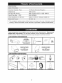 5
5
-
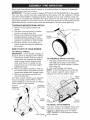 6
6
-
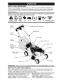 7
7
-
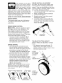 8
8
-
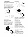 9
9
-
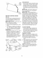 10
10
-
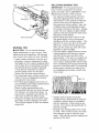 11
11
-
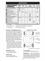 12
12
-
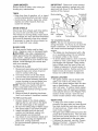 13
13
-
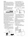 14
14
-
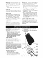 15
15
-
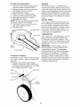 16
16
-
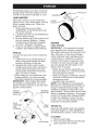 17
17
-
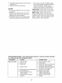 18
18
-
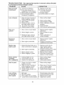 19
19
-
 20
20
-
 21
21
-
 22
22
-
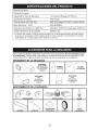 23
23
-
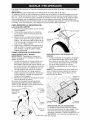 24
24
-
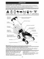 25
25
-
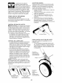 26
26
-
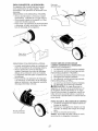 27
27
-
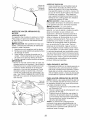 28
28
-
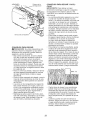 29
29
-
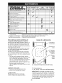 30
30
-
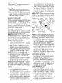 31
31
-
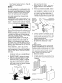 32
32
-
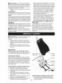 33
33
-
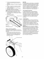 34
34
-
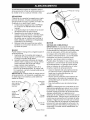 35
35
-
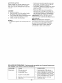 36
36
-
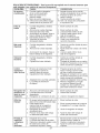 37
37
-
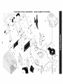 38
38
-
 39
39
-
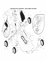 40
40
-
 41
41
-
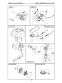 42
42
-
 43
43
-
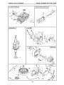 44
44
-
 45
45
-
 46
46
-
 47
47
-
 48
48


Husqvarna 917.374471 El manual del propietario
- Categoría
- Cortadoras de césped
- Tipo
- El manual del propietario
- Este manual también es adecuado para
En otros idiomas
- English: Husqvarna 917.374471 Owner's manual