DeDietrich DTG764X El manual del propietario
- Tipo
- El manual del propietario

GUIDE D’INSTALLATION ET D’UTILISATION
FR - Table de cuisson
GUIDE FOR INSTALLATION AND USE
GB - Cooking Hob
MANUALE D’INSTALLAZIONE ED UTILIZZO
IT - Piano di Cottura
INSTALAČNÍ A UŽIVATELSKÁ PŘÍRUČKA
CZ - Varná deska
MANUAL DE INSTALACIÓN Y UTILIZACIÓN
ES - Placa de cocción
GUIA DE INSTALAÇÃO E DE UTILIZAÇÃO
PT - Placa de cozinha
INSTALLATIONS- OG BRUGERVEJLEDNING
DK - Kogeplade
SZERELÉSI ÉS HASZNÁLATI UTASÍTÁS
HU - Főzőlap

1
Chère Cliente, Cher Client,
Vous venez d’acquérir une table DE DIETRICH et nous vous en remercions.
Nos équipes de recherche ont conçu pour vous cette nouvelle génération d’appareils,
qui par leur qualité, leur esthétique, leurs fonctions et leurs évolutions technologiques en
font des produits d’exception, révélateurs de notre savoir-faire.
Votre nouvelle table DE DIETRICH s’intègrera harmonieusement dans votre cuisine et
alliera parfaitement les performances de cuisson, et la facilité d’utilisation. Nous avons
voulu vous offrir un produit d’excellence.
Vous trouverez également dans la gamme des produits DE DIETRICH, un vaste choix de
fours, de fours à micro-ondes, de hottes aspirantes, de lave-vaisselle, et de réfrigérateurs
intégrables, que vous pourrez coordonner à votre nouvelle table DE DIETRICH.
Bien entendu, dans un souci permanent de satisfaire le mieux possible vos exigences
vis- à-vis de nos produits, notre service consommateurs est à votre disposition et à votre
écoute pour répondre à toutes vos questions ou suggestions (coordonnées à la fin de
ce livret).
Et retrouvez-nous aussi sur notre site www.dedietrich-electromenager.com sur
lequel vous trouverez nos dernières innovations ainsi que des informations utiles et
complémentaires.
DE DIETRICH
Les nouveaux objets de valeur
Dans le souci d’une amélioration constante de nos produits, nous nous réservons le droit d’apporter à
leurs caractéristiques techniques, fonctionnelles ou esthétiques toutes modifications liées à leur évolution.
Important : Avant de mettre votre appareil en route, veuillez lire attentivement ce
guide d’installation et d’utilisation afin de vous familiariser plus rapidement à son
fonctionnement.
www.dedietrich-electromenager.com
FR

2
SOMMAIRE
AVERTISSEMENTS GENERAUX pag.4
INSTRUCTIONS POUR L’UTILISATEUR pag.5
Utilisation des bruleurs pag.5
Emploi de la plaque électrique pag.5
Nettoyage pag.6
INSTRUCTIONS POUR L’INSTALLATEUR pag.7
Montage de la table de cuisson pag.7
Fixation de la table de cuisson pag.7
Pièce d’installation pag.7
Branchement gaz pag.8
Branchement électrique pag.8
Remplacement des injecteurs pag.8
Réglage des brûleurs pag.8
Remplacement câble d’alimentation pag.9
MODÈLES pag.10
TABLE DE CARATERISTIQUES TECHNIQUES pag.11
SERVICE APRES-VENTE ET RELATIONS CONSOMMATEURS pag.12
-
-
-
-
-
-

3
Il est très important que ce manuel soit conservé avec l’appareil afin de pouvoir être consulté
en cas de besoin. Si l’appareil est vendu ou donné à une autre personne, il faut s’assurer que ce
manuel est donné en même temps, de façon à ce que le nouvel utilisateur soit informé sur son
fonctionnement et prenne connaissance des avertissements correspondants.
Cet appareil appartient à la classe 3 et il a été conçu pour un usage uniquement domestique.
Le fabricant décline toute responsabilité en cas de dommages aux choses ou aux personnes
dûs à une installation incorrecte ou à une utilisation inadéquate, erronée ou non raisonnable de
l’appareil.
Cette appareil conforme aux directives:
EEC 90/396 (Gaz) EEC 89/336 (Compatibilité électromagnétique)
2006/95/CE (Basse tension) EEC 89/109 (Contact avec aliments)
L’installation doit être effectuée par du personnel compétent et qualifié conformément aux normes en
vigueur.
Cet appareil a été conçu pour être utilisé par des adultes.
Il faut donc veiller à ce que les enfants ne s’en approchent pas dans l’intention de jouer avec celui-ci.
Surveiller les enfants pendant le fonctionnement de l’appareil et veiller à ce qu’ils ne restent pas à
proximité et qu’ils ne touchent pas les surfaces qui n’ont pas encore complètement refroidi.
Avant d’alimenter l’appareil, contrôler qu’il est correctement réglé pour le type de gaz à disposition (voir
paragraphe “Installation”).
Avant l’entretien et le nettoyage, débrancher électriquement l’appareil et le laisser refroidir.
S’assurer qu’il y a une circulation d’air autour de l’appareil au gaz. Une faible ventilation entraîne une
carence d’oxygène.
Si l’appareil est utilisé de manière intense ou prolongée, il peut être nécessaire de prévoir une aération
supplémentaire, en ouvrant par exemple une fenêtre ou en augmentant la puissance de l’aspiration
mécanique si celle-ci existe.
Les produits de la combustion doivent être évacués à l’extérieur avec une hotte aspirante ou un ventilateur
électrique (voir paragraphe “Installation”).
Pour les éventuelles interventions ou modifications, s’adresser à un Centre d’Assistance Technique agréé
et exiger des pièces de rechange originales.
ATTENTION:
L’étiquette produit, avec le numéro de série, est placée au dessous de la table de cuisson.
-
-
-
-
-
-
-
-
-
-
AVERTISSEMENTS GENERAUX

4
INSTRUCTIONS POUR L’UTILISATEUR
Toutes les opérations relatives à l’installation, au réglage et à l’adaptation au type
de gaz disponible doivent être effectuées par du personnel qualifié, conformément
aux normes en vigueur.
Les instructions spécifiques sont reportées dans la partie du manuel réservée à
l’installateur.
UTILISATION DES BRULEURS
Le symbole appliqué par sérigraphie à côté du
bouton indique à quel brûleur celui-ci correspond.
Allumage automatique avec soupape de
sécurité
Tourner dans le sens inverse des aiguilles d’une
montre le bouton correspondant jusqu’à la position
de maximum (grande flamme, fig.1) et appuyer sur
le bouton.
Une fois l’allumage
obtenu, maintenir le
bouton appuyé pendant
environ 6 secondes.
Pour obtenir un
rendemen t optimal
sans gaspillage de gaz,
il est important que le
diamètre de la casserole
soit adapté au potentiel du brûleur (voir tableau
ciaprès), de façon à éviter que la flamme sorte du
fond de la casserole (fig.2).
Utiliser le débit maximal pour amener rapidement
à ébullition les liquides et le débit réduit pour
réchauffer les aliments ou pour maintenir
l’ébullition.
Toutes les positions de fonctionnement doivent être
choisies entre celles de maximum et de minimum
et jamais entre celle de maximum et le point de
fermeture.
Pour interrompre l’alimentation en gaz, tourner le
bouton dans le sens des aiguilles d’une montre
jusqu’à la position de fermeture.
En cas d’absence d’énergie électrique, il est
possible d’allumer les brûleurs avec des allumettes
en positionnant le bouton sur le point d’allumage
(grande flamme, fig.1).
Brûleurs Puissance (W) Ø Casseroles
Auxiliaire 1000 10 - 14 cm
Semi-rapide 1750 16 - 18 cm
Rapide 3000 20 - 22 cm
Triple couronne 3800 24 - 26 cm
Avertissements
Contrôler toujours que les boutons sont sur la
position “fermé” (voir fig.1) quand l’appareil ne
fonctionne pas.
Si la flamme s’éteint accidentellement, après
quelques secondes, la soupape de sécurité
interrompt automatiquement l’arrivée du gaz.
Pour rétablir le fonctionnement, reporter le bouton
au point d’allumage (grande flamme, fig.1) et
appuyer sur le bouton.
Pendant la cuisson avec des graisses et des
huiles, faire particulièrement attention car
celles-ci, si elles sont surchauffées, peuvent
s’enflammer.
Ne pas utiliser de vaporisateurs près de l’appareil
en fonction.
Il ne faut pas poser sur les brûleurs des casseroles
instables ou déformées afin d’éviter des accidents
de renversement ou de débordement.
S’assurer que les poignées des casseroles soient
positionnées correctement.
Quand on allume le brûleur, contrôler que la
flamme est régulière; abaisser toujours la flamme
ou l’éteindre avant d’enlever la casserole.
EMPLOI DE LA PLAQUE ÉLECTRIQUE
La plaque est commandée par un commutateur à
7 positions et son activation s’effectue en tournant
le bouton sur la position désirée.
Un voyant signale, en s’allumant, la mise sous
tension de la plaque.
A titre indicatif, un tableau avec les réglages de la
plaque est reporté ci-après.
Avertissements
Utiliser des casseroles ayant un fond plat et de
diamètre égal ou légèrement supérieur à celui de
la plaque.
-
-
-
-
-
-
-
-
Fig.1
Fig.2

5
NETTOYAGE
Avant toute opération de nettoyage, débrancher
l’appareil du réseau d’alimentation électrique.
Il est conseillé d’opérer quand l’appareil est froid
Parties émaillées
Les parties émaillées doivent être nettoyés avec
une éponge et de l’eau savonneuse ou avec un
détergent léger.
Ne pas utiliser de produits abrasifs ou corrosifs.
Eviter que les substances comme le jus de citron,
la tomate, l’eau salée, le vinaigre, le café et le
lait restent pendant longtemps sur les surfaces
émaillées.
Parties en acier inoxydable et aluminium
Des taches peuvent se former sur l’acier inox s’il
reste longtemps en contact avec de l’eau calcaire
ou des détergents agressifs.
Il est conseillé de laver avec de l’eau savonneuse
et de sécher avec un chiffon doux.
Le brillant se garde en utilisant périodiquement des
produits chimiques spécifiques se trouvant dans le
commerce.
Brûleurs et grilles
Ces parties peuvent être enlevées pour faciliter le
nettoyage.
Les brûleurs doivent être nettoyés avec une
éponge et de l’eau savonneuse ou avec un
détergent léger, bien essuyés et remis parfaitement
dans leur siège.
Contrôler que les canaux de répartition des
flammes ne sont pas bouchés.
Vérifier que la sonde de la soupape de sécurité et
l’électrode d’allumage sont toujours bien propres
afin de garantir un fonctionnement optimal.
Les grilles peuvent être lavées en lave-vaisselle.
Robinets de gaz
L’éventuel graissage des robinets doit être effectué
exclusivement par du personnel spécialisé.
Si les robinets de gaz deviennent difficiles à
tourner ou ont un fonctionnement anormal,
appeler le Service d’Assistance.
INSTRUCTIONS POUR L’UTILISATEUR
POSITION
BOUTON
INTENSITÉ
CHALEUR TYPE DE CUISSON
0 Éteint
1 Faible Pour mantenir les aliments chauds et pour réchauffer une
petite quantité de liquide.
2 Doux Pour réchauffer une quantité moyenne de liquide; pour la
préparation de crèmes et sauces à longue cuisson.
3 Lent Pour décongeler, pour cuir à l’étuvée, pour cuisson au-dessous
de la température d’ébullition.
4 Moyen Cuisson à la température d’ébullition, rôtis, viandes délicates,
poisson.
5 Fort Pour rôtis, biftecks, pot-au-feu.
6Vif
Pour porter à l’ébullition une grande quantité de liquide, frire,
griller.
Ne jamais laisser la plaque allumée si elle est
vide.
Ne pas cuisiner les aliments directement sur la
plaque.
Eteindre la plaque quelques minutes avant la fin
de la cuisson.
Après l’utilisation, la plaque reste longtemps
chaude: ne pas poser dessus les mains ou des
objets.
-
-
-
-
Pour mieux la préserver, traiter la surface de la
plaque avec les produits spécifiques facilement
trouvables dans le commerce.
NB. Lors de sa première mise sous tension,
laisser la plaque allumée sur la position 1
pendant environ 30 minutes afin d’éliminer les
résidus.
-

6
INSTALLATION
Montage de la table de cuisson
L’appareil est fabriqué pour être encastré dans des
meubles résistant à la chaleur.
Les parois des meubles doivent résister à une
température de 75°C en plus de la température
ambiante, conformément aux normes
européennes.
L’appareil est de type “Y”, c’est-à-dire qu’il peut
être installé avec une seule paroi latérale, à droite
ou à gauche de la table de cuisson.
Eviter d’installer l’appareil à proximité de matériaux
inflammables comme des rideaux, des torchons,
etc..
Pratiquer une ouverture, dans le plateau du
meuble, des dimensions indiquées en fig.3, en
respectant une distance d’au moins 50 mm entre le
bord de l’appareil et
les parois voisines.
MODÈLE L (mm) P (mm)
DTE714X / W / F / B
DTE715X / W / F / B
DTE772X / W / F / B
DTG764X
DTG775X
560 480
DTE792X
DTG795X 860 480
En cas de présence d’une armoire murale au-
dessus de la table de cuisson, il faut prévoir une
distance minimale de 760 mm entre celle-ci et le
plan de travail. Il est conseillé d’isoler l’appareil du
meuble se trouvant audessous avec un séparateur
en laissant un espace de dépression d’au moins
10 mm (fig. 4).
En cas
d’encastrement
sur une base
avec four, il
faudra s’assurer
que l’installation
réponde aux
normes de sécurité
en vigueur. I faudra
en particulier veiller à ce que le câble électrique et
le tuyau d’alimentation soient placés de façon à
ce qu’ils n’entrent pas en contact avec les parties
chaudes de l’enveloppe du four. De plus, en cas
d’installation au-dessus d’un four encastré sans
ventilation de refroidissement, il faudra prévoir,
pour obtenir une aération adéquate, des prises
d’air avec entrée par le bas d’au moins 200 m2 et
sortie dans la partie supérieure d’au moins 60 cm2.
Fixation de la table de cuisson
Chaque table de cuisson est accompagnée d’un
joint spécial. De plus, une série de crochets à
utiliser pour la fixation de la table est également
fournie.
Pour l’installation, procéder de la façon suivante:
Enlever les grilles et les brûleurs de la table de
cuisson.
Retourner l’appareil et appliquer le joint adhésif S
le long du bord externe du verre (fig. 5).
Fig.5 Fig.6
Insérer et positionner la table de cuisson dans
l’ouverture pratiquée dans le meuble et la bloquer
avec les vis des crochets de fixation C (fig. 6).
Pièce d’installation
Cet appareil n’est pas équipé d’un dispositif
d’évacuation des produits de la combustion, il
-
-
-
INSTRUCTIONS POUR L’INSTALLATEUR
AVERTISSEMENT IMPORTANT
LES OPERATIONS REPORTEES CI-APRES DOIVENT ETRE EXECUTEES DANS LE
RESPECT DES NORMES EN VIGUEUR, EXCLUSIVEMENT PAR DU PERSONNEL
QUALIFIE. LE FABRICANT DECLINE TOUTE RESPONSABILITE POUR LES DOMMAGES
AUX PERSONNES, ANIMAUX ET CHOSES DERIVANT DU NON-RESPECT DE CES
DISPOSITIONS.
Fig.3
Fig.4

7
INSTRUCTIONS POUR L’INSTALLATEUR
est donc nécessaire d’évacuer les fumées vers
l’extérieur en utilisant une hotte ou un ventilateur
électrique qui soit mis en marche à chaque fois
que l’on utilise l’appareil.
La pièce où est installé l’appareil doit avoir un
afflux d’air naturel pour la combustion régulière
du gaz et pour la ventilation de la pièce; le volume
d’air nécessaire ne doit pas être inférieur à 20 m3.
L’afflux d’air doit s’effectuer par une ouverture
permanente pratiquée sur les murs de la pièce et
communicante avec l’extérieur.
La ventilation peut également provenir d’une pièce
contiguë, dans ce cas respecter les normes en
vigueur à ce sujet.
Les ouvertures doivent avoir une section minimale
de 200 cm2.
Branchement gaz
S’assurer que l’appareil est adéquat pour le type
de gaz disponible; pour cela se référer à l’étiquette
placée sous l’appareil. Opérer conformément
aux instructions reportées au paragraphe
“transformations gaz et réglages” pour l’éventuelle
adaptation à des gaz différents.
L’appareil doit être raccordé à l’installation du gaz
en utilisant des tubes métalliques rigides ou avec
des tuyaux flexibles en acier à paroi continue
conformes aux
normes en
vigueur.
Certains modèles
sont équipés
de systèmes
cylindriques A et
coniques B pour
le raccordement au gaz (fig. 7). Sélectionnez le
type adéquat pour un raccordement optimal.
Le raccordement ne doit pas provoquer de
sollicitations à la rampe de gaz.
Une fois l’installation terminée, contrôler
l’étanchéité des raccordements avec une
solution savonneuse.
Branchement électrique
Le branchement au réseau électrique doit être
exécuté par du personnel qualifié conformément
aux normes en vigueur.
La tension de l’installation électrique doit
correspondre à celle indiquée sur l’étiquette
située sous l’appareil. Vérifier que l’installation
est équipée d’un branchement à la terre efficace
conformément aux normes et aux dispositions de
loi. La mise à la terre est obligatoire.
Si l’appareil est sans fiche, appliquer au câble
d’alimentation une fiche normalisée.
Il est possible d’effectuer directement le
branchement au réseau électrique en interposant
un interrupteur omnipolaire ayant une distance
d’ouverture des contacts d’au moins 3 mm.
TRANSFORMATIONS GAZ ET REGLAGES
Remplacement des injecteurs
Si l’appareil est prévu pour un type de gaz différent
de celui disponible, il faut
remplacer les injecteurs
des brûleurs.
Le choix des injecteurs
à remplacer doit être
fait selon le tableau
“caractéristiques
techniques” annexé.
Procéder ensuite de la manière suivante:
Enlever les grilles et les brûleurs.
Avec une clé droite L, dévisser la injecteur U
(fig.8) et la remplacer par la injecteurs adéquate.
Bloquer énergiquement la injecteurs.
Réglage des brûleurs
Le réglage du minimum doit toujours être correct
et la flamme doit toujours rester allumée même en
cas de passage rapide de la position de maximum
à celle de minimum.
Si ce n’est pas le cas, il faut régler le minimum de
la manière suivante:
Allumer le brûleur;
Tourner le robinet jusqu’à la position de minimum
(petite flamme);
Enlever le bouton de la tige du robinet;
Introduire un tournevis à pointe plate C dans le
trou du panneau de commandes (fig. 9) et tourner
la vis by-pass V (fig. 9/A) jusqu’au réglage correct
du minimum.
Fig.9 Fig.9/A
Pour les brûleurs fonctionnant au gaz G30, la
vis by-pass doit être complètement vissée.
-
-
-
-
-
-
-
Fig.7
Fig.8
V

8
ENTRETIEN
Remplacement câble d’alimentation
En cas de remplacement du câble d’alimentation,
il faut utiliser un
câble conforme
aux normes du
type H05VV-F
ou H05RR-F de
section 3x0,75
mm2 pour table
de cuisson à gaz
ou section 3 x 1 mm2 pour table de cuisson mixte
avec 1 plaque électrique (1500 W).
Le branchement au bornier doit être effectué
comme indiqué en fig. 10:
câble L marron (phase)
câble N bleu (neutre)
câble vert-jaune (terre)
INSTRUCTIONS POUR L’INSTALLATEUR
Fig.10

9
1 Brûleur rapide de 3000 W
2 Brûleur semi-rapide de 1750 W
3 Brûleur auxiliaire de 1000 W
4 Brûleur triple couronne de 3800 W
5 Plaque électrique Ø 145 mm 1500 W
8 Bouton commande brûleur
DTG764X
DTG775X DTG795X
1
8
3
4
2
2
1
8
3
4
2
2
DTE714X / W / F / B DTE715X / W / F / B
1
8
3
2
4
5
8
3
2
4
DTE772X / W / F / B DTE792X
1
8
3
4
2
2
1
8
3
4
2
2
MODÈLES

10
TABLE DE CARATERISTIQUES TECHNIQUES
BRULEURS
GAZ
PRESSION
DE
SERVICE
DEBIT DIAMÈTRE
INJECTEUR
DIAMÈTRE
BY PASS
ROBINET
DEBITS
CALORIFIQUES
(W)
N° DESIGNATION mbar g/h L/h 1/100 mm 1/100 mm Max. Min.
1 RAPIDE G30 / G31 28 - 30 / 37 225 - 85 42 3000 950
G20 20 - 290 115Y Reg. 3000 950
2 SEMI-RAPIDE G30 / G31 28 - 30 / 37 126 - 65 31 1750 600
G20 20 - 165 97Z Reg. 1750 600
3 AUXILIAIRE G30 / G31 28 - 30 / 37 71 - 50 27 1000 450
G20 20 - 99 72X Reg. 1000 450
4TRIPLE
COURONNE
G30 / G31 28 - 30 278 - 98 60 3800 2100
G20 20 - 367 135K Reg. 3800 2100
Ce produit est conforme à la Directive EU 2002/96/EC.
Le logo « poubelle barrée » fi gurant sur l’appareil indique qu’au terme de son cycle de
vie, cet appareil doit être, non seulement traité séparément des déchets domestiques, mais
aussi remis à un centre de récupération pour équipements électriques et électroniques ou
bien au revendeur lors de l’achat d’un appareil neuf équivalent.
Une fois l’appareil au terme de son cycle de vie, l’utilisateur est tenu de le remettre aux structures de
récupération prévues à cet effet, sous peine des sanctions prévues par la législation en vigueur en matière
de déchets.
Une collecte sélective adéquate permettant d’envoyer l’équipement éliminé au recyclage, au traitement et
à l’élimination compatible sur le plan environnemental contribue à éviter de possibles effets négatifs sur
l’environnement et la santé et facilite le recyclage des matériaux dont le produit est constitué.
Pour plus de détails quant aux systèmes de récupération disponibles, s’adresser au service local chargé
de l’élimination des déchets ou au magasin où l’équipement a été acheté.
Les producteurs et les importateurs respecteront leurs obligations en vue du recyclage, du traitement et de
l’élimination compatible sur le plan environnemental aussi bien directement qu’en participant à un système
collectif.
Le fabricant décline toute responsabilité pour les éventuelles inexactitudes, imputables à des erreurs
d’impression ou de transcription, contenues dans ce manuel. Il se réserve le droit d’apporter à ses produits toutes
les modifi cations qu’il estimera opportunes, sans nuire aux caractéristiques essentielles de fonctionnement et de
sécurité.

11
INTERVENTIONS
Les éventuelles interventions sur votre appareil
doivent être effectuées par un professionnel
qualifié dépositaire de la marque. Lors de votre
appel, mentionnez la référence complète de votre
appareil (modèle, type, numéro de série). Ces
renseignements figurent sur la plaque signalétique
PIÈCES D’ORIGINE
Lors d’une intervention d’entretien, demandez
l’utilisation exclusive de pièces détachées certifiées
d’origine.
RELATIONS CONSOMMATEURS
Pour en savoir plus sur tous les produits de la
marque : informations, conseils, les points de
vente, les spécialistes après-vente.
Pour communiquer:
nous sommes à l’écoute de toutes vos remarques,
suggestions, propositions auxquelles nous vous
répondrons personnellement.
Vous pouvez nous écrire :
Service Consommateurs
DE DIETRICH
BP 9526
95069 CERGY PONTOISE CEDEX
ou nous téléphoner au:
0892 02 88 04
SERVICE APRES-VENTE ET RELATIONS CONSOMMATEURS

1
Dear Customer,
You have just acquired a DE DIETRICH hob and we would like to thank you.
Our research teams have created a new generation of appliances for you. Their quality,
design, features and technological advances make them exceptional products and
reveal our unique know-how.
Your new DE DIETRICH hob will blend harmoniously into your kitchen and perfectly
combine cooking performance and ease of use. Our wish was to offer you a product of
excellence.
In the line of DE DIETRICH products, you will also find a wide range of ovens, microwave
ovens, ventilation hoods, dishwashers, and refrigerators, all of which can be integrated
and all of which can be coordinated with your new DE DIETRICH hob.
Of course, in an ongoing effort to better satisfy your demands with regard to our products,
our after-sales service department is at your disposal and ready to listen in order to
respond to all of your questions and suggestions (contact information at the end of this
booklet).
We also encourage you to visit our Web site www.dedietrich-electromenager.com
where you will find our latest innovations as well as useful and complementary
information.
DE DIETRICH
The New Items of Value
As part of our commitment to constantly improving our products, we reserve the right to make changes to
them based on advances to their technical, functional and/or esthetic properties.
Before installing and using your appliance, please carefully read this Guide for
Installation and Use, which will allow you to quickly familiarise yourself with its
operation.
www.dedietrich-electromenager.com
GB

2
TABLE OF CONTENTS
GENERAL NOTICE pag.4
INSTRUCTION FOR THE USER pag.5
Using the burners pag.5
Electric plate use pag.5
Cleaning pag.6
INSTRUCTION FOR THE INSTALLER pag.7
Installing the top pag.7
Fastening the top pag.7
Installation room pag.7
Gas connection pag.8
Electric connection pag.8
Replacing the nozzles pag.8
Adjusting the burners pag.8
Replacing the power supply cable pag.9
MODEL pag.10
TECHNICAL CHARACTERISTIC TABLES pag.11
AFTER SALES SERVICE pag.12
-
-
-
-
-
-

3
It is very important that you keep this booklet together with the equipment for any future
consultation.
If this equipment should be sold or transferred to another person, make sure that the new
user receives the booklet, so that he can learn how to operate the appliance and read the
corresponding notice.
This is a Class 3 appliance.
The manufacturer refuses all responsibility for possible damages to things or people, resulting
from a wrong installation or from an improper, incorrect or unreasonable use of this equipment.
GENERAL NOTICE
This appliance complies with the following Directives:
EEC 90/396 (Gas) EEC 89/336 (Electromagnetic Compatibility)
2006/95/CE (Low Voltage) EEC 89/109 (Contact with foods)
The installation must be carried out by experienced and qualified personnel, in conformity with the
regulations in force.
This equipment has been designed to be used by adults.
Therefore, make sure that children do not go near the equipment to play with it.
While the appliance is running, watch the children and make sure they neither stay near the equipment,
nor touch the surfaces that have not cooled down completely.
Before powering the equipment, check that it is properly adjusted for the type of gas at disposal (see the
“installation” paragraph).
Before carrying out the maintenance or cleaning the equipment, cut power supply off and make it cool
down.
Make sure that air circulates around the gas equipment. Insufficient ventilation produces a lack of oxygen.
In case of an intense or prolonged use of the equipment, it may be necessary to improve aeration, for
example by opening a window or increasing the mechanical suction power, if it exists.
The products of combustion must be discharged outside through a suction hood or an electric fan (see the
“installation” paragraph).
For any possible operation or modification, apply to an authorized Technical Assistance Centre and
demand original spare parts.
The product label, with the serial number, is sticked under the hob.
-
-
-
-
-
-
-
-
-
-

4
INSTRUCTIONS FOR THE USER
It is necessary that all the operations regarding the installation, adjustment and
adaptation to the type of gas available are carried out by qualified personnel, in
conformity with the regulations in force.
The specific instructions are described in the booklet section intended for the
installer.
USING THE BURNERS
The symbols silk-screen printed on the side of the
knob indicate the correspondence between the
knob and the burner.
Automatic start-up with valves
Turn the corresponding knob anticlockwise up
to the maximum position (large flame, fig. 1) and
press the knob.
Once the burner has
been started up, keep
the knob pressed for
about 6 seconds.
Using the burners
In order to obtain the
maximum yield without
waste of gas, it is
important that the diameter
of the pot is suitable for the burner potential (see
the following table), so as to avoid that the flame
goes out of the pot bottom (fig. 2).
Use the maximum capacity to quickly make the
liquids reach the boiling temperature, and the
reduced capacity to heat food or maintain boiling.
All of the operating positions must be chosen
between the maximum and the minimum ones,
never between the minimum position and the
closing point.
Use the maximum capacity to quickly make the
liquids reach the boiling temperature, and the
reduced capacity to heat food or maintain boiling.
All of the operating positions must be chosen
between the maximum and the minimum ones,
never between the minimum position and the
closing point.
The gas supply can be interrupted by turning the
knob clockwise up to the closing position.
If there is no power supply, it is possible to light the
burners with matches, setting the knob to the start-
up point (large flame, fig. 1).
BURNERS Power W Ø of pots
Auxiliary 1000 10 - 14 cm
Semi-rapid 1750 16 - 18 cm
Rapid 3000 20 - 22 cm
Triple crown 3800 24 - 26 cm
Notice
When the equipment is not working, always check
that the knobs are in the closing position (see
fig.1).
If the flame should blow out accidentally, the safety
valve will automatically stop the gas supply, after a
few seconds. To restore operation, set the knob to
the lighting point (large flame, fig. 1) and press.
While cooking with fat or oil, pay the utmost
attention as these substances can catch fire when
overheated.
Do not use sprays near the appliance in operation.
Do not place unstable or deformed pots on the
burner, so as to prevent them from overturning or
overflowing.
Make sure that pot handles are placed properly.
When the burner is started up, check that the
flameis regular and, before taking pots away,
always lowerthe flame or put it out.
ELECTRIC PLATE USE
The electric-plate is operated with a seven position
switch and to turn the electric-plate on, rotate the
switch to any of the positions shown.
The red light is switched on when the electric-plate
is in operation.
Below as indicative basis, the settings to be used
for operating the electric-plate.
Warning
Use only flat pans and with sufficiently thick base,
equal or not much superior than that of the plate.
Do not switch the electric plate without the pan
over the plate.
Do not cook any food on the plate surface.
Turn off the plate few minutes before the cooking
end.
-
-
-
-
-
-
-
-
-
-
-
Fig.1
Fig.2

5
INSTRUCTIONS FOR THE USER
After use the electric plate remains very hot for
a prolonged period of time, do not tuch it and do
not place any object on top of the plate.
For a good preservation, the electric plate must
be thoroughly cleaned with appropriate cleaning
products which are readly available.
-
-
NB.: When operating for the first time, it is
necessary to eliminate any humidity or oil
which may accumulated around the electric
elements of the plate by operating the electric
plate on its lowest setting (1) for about 30
minutes.
KNOB
SETTING HEAT TYPE OF COOKING
0Off
1 Very low To heat small quantities of liquids.
2 Low Heating medium quantities of liquid, to prepare sauces and
creams requiring long cooking.
3 Mild To defrost frozen foods, cook stews, at to below boiling point.
4 Medium For foods which require boiling point, delicate meat and fi sh.
5 Strong For roasting, grilling, stews.
6 Very strong To boil large quantities of liquid, to fry.
CLEANING
Before any operation, disconnect the appliance
from the electric grid.
It is advisable to clean the appliance when it is
cold.
Enamelled parts
The enamelled parts must be washed with a
sponge and soapy water or with a light detergent.
Do not use abrasive or corrosive products.
Do not leave substances, such as lemon or tomato
juice, salt water, vinegar, coffee and milk on the
enamelled surfaces for a long time.
Stainless steel an alluminum parts
Stainless steel can be stained if it remains in
contact with highly calcareous water or aggressive
detergents for an extended period of time.
The stainless steel parts should also be cleaned
with soapy water and then dried with a soft cloth.
Burners and racks
These parts can be removed to make cleaning
easier.
The burners must be washed with a sponge and
soapy water or with a light detergent, wiped well
and placed in their housing perfectly.
Make sure that the flame-dividing ducts are not
clogged.
Check that the feeler of the safety valve and the
start-up electrode are always perfectly cleaned, so
as to ensure an optimum operation.
The racks can be washed in the dishwasher.
Gas taps
The possible lubrication of the taps must be carried
out by specialized personnel, exclusively.
In case of hardening or malfunctions in the gas
taps, apply to the Customer Service.

6
INSTALLATION
Installing the top
The appliance is designed to be embedded into
heat-resistant pieces of furniture.
The walls of the pieces of furniture must resist a
temperature of 75°C besides the room one.
The gas hobs are equipped with type X degree
protection against overheating. Therefore,
the appliance can be installed next to cabinets,
provided the height of the cabinet doses not
exceed that of the hob.
The equipment must not be installed near
inflammable materials, such as curtains, cloths,
etc.
Make a hole in the top of the piece of furniture, with
the dimensions indicated in fig. 3, at a distance of
at least 50 mm from
the appliance border
to the adjacent
walls.
MODEL L (mm) P (mm)
DTE714X / W / F / B
DTE715X / W / F / B
DTE772X / W / F / B
DTG764X
DTG775X
560 480
DTE792X
DTG795X 860 480
Any possible wall unit over the cook-top must be
placed at a distance of at least 760 mm from the
top.
It is advisable to isolate the appliance from the
piece of furniture below with a separator, leaving a
depression space of at least 10 mm (fig. 4).
If the hob is going
to be installed on
the top of an oven,
precautions must be
taken to guarantee
an installation in
accordance with
current accident
prevention
standards. Pay
particular attention to the position of the electric
cable and gas pipe: they must not touch any hot
parts of the oven.
Moreover, if the hob is going to be installed on
the top of a built in oven without forced cooling
ventilation, proper air vents must be installed to
guarantee an adequate ventilation, with the lower
air entering with a cross section of at least 200cm2,
and the higher air exiting with a cross section of at
least 60 cm2.
Fastening the top
Every cook-top is equipped with a special washer.
A set of hooks is also supplied for mounting the
cook-top.
For the installation proceed as follows:
Remove the racks and burners from the top.
Turn the appliance upside down and lay the
washer S along the external border (fig. 5).
Fig.5 Fig.6
Introduce and place the cook-top in the hole made
in the piece of furniture, then block it with the V
screws of the fastening hooks G (fig.6.
Installation room
This appliance is not provided with a device for
exhausting the products of combustion. Regarding
-
-
-
INSTRUCTIONS FOR THE INSTALLER
IMPORTANT NOTICE:
THE OPERATIONS INDICATED BELOW MUST BE FOLLOWED BY QUALIFIED
PERSONNEL EXCLUSIVELY, IN CONFORMITY WITH THE REGULATIONS IN FORCE.
THE MANUFACTURING FIRM REFUSES ALL RESPONSIBILITY FOR DAMAGES TO
PEOPLE, ANIMALS OR THINGS, RESULTING FROM THE FAILURE TO COMPLY WITH
SUCH PROVISIONS.
Fig.3
Fig.4

7
room ventilation rules where appliance is installed
make reference to the legislation, in conformity
with the local regulations.
FOR THE U.K. ONLY
The room containing this hotplate should have an
air supply in accordance with BS 5440: Part 2:
1989.
All rooms require an openable window, or
equivalent and some rooms will require a
permanent vent a well.
For room volumes up to 5 m3 an air vent of 100cm2
is required.
For room volumes between 5 m3 and 10 m3 an air
vent of 50 cm2 is required.
If the room is greater than 5 m3 and has a door that
opens directly to the outside, then no air vent is
required.
If there are other fuel burning appliances in the
same room BS 5440: Part 2:1989 should be
consulted to determine the air vent requirements.
Gas connection
Make sure that the appliance is adjusted for
the gas type available (see the label under the
appliance). Follow the instructions indicated in
the chapter “gas
transformations
and adjustments”
for the possible
adaptation to
different gases.
The appliance
must be
connected to the gas system by means of stiff metal
pipes or flexible steel pipes having continuous
walls, in compliance with the regulations in force.
Some models are equipped with both cylindrical A
and conical B connectors for gas supply (fig. 7).
Please select the type which is correct for the
supply concerned.
The connection must not stress the gas ramp.
Once the installation is over, check the
connection seal with a soapy solution.
Electric connection
The connection to the electric grid must be carried
out by qualified personnel and in conformity with
the regulations in force.
The voltage of the electric system must correspond
to the value indicated in the label under the
appliance. Make sure that the electric system is
-
-
-
-
provided with an effective ground connction in
compliance with the regulations and provisions of
the law. Grounding is compulsory.
If the appliance is not equipped with a plug, apply
a standardized plug to the power supply cable.
It is possible to effect the connection to the electric
grid directly, by interposing an omnipolar switch
having a contact opening distance of at least 3
mm.
GAS TRANSFORMATIONS AND ADJUSTMENTS
Replacing the nozzles
If the equipment is adjusted for a type of gas that is
different from the one available, it is necessary to
replace the burner nozzles.
The choice of the nozzles to replace must be
made according to the table of the “technical
characteristics” as enclosed.
Act as follows:
Remove the racks and
burners.
By means of a straight
spanner L, unscrew
the nozzle U (fig.8) and
substitute it with the
corresponding one.
Tighten the nozzle strongly.
Adjusting the burners
The lowest flame point must always be properly
adjusted and the flame must remain on even if
there is an abrupt shift from the maximum to the
minimum position.
If this is not so, it is necessary to adjust the lowest
flame point as follows:
start the burner up;
turn the tap up to the minimum position (small
flame);
remove the knob from the tap rod;
introduce a flat-tip screwdriver C in the hole of
control panel of the tap (fig. 9) and turn the by-
pass screw V (fig.9/A) up to a proper adjustment
of the lowest flame point.
Fig.9 Fig.9/A
As regards G30 gas burners, the by-pass screw
must be tightened completely.
-
-
-
-
-
-
-
V
INSTRUCTIONS FOR THE INSTALLER
Fig.7
Fig.8

8
MAINTENANCE
Replacing the power supply cable
If the power supply cable should be replaced,
it is necessary
to use a cable
with a section
of 3x0.75mm2
for the version
all gas and 3x1
mm2 for the
version mixed,
type HO5VV-F or H05RR-F, complying with the
regulations in force.
The connection to the terminal board must be
effected as shown in fig.10:
brown cable L (phase)
blue cable N (neutral)
green-yellow cable (ground)
INSTRUCTIONS FOR THE INSTALLER
Fig.10

9
DTG764X
DTG775X DTG795X
1
8
3
4
2
2
1
8
3
4
2
2
DTE714X / W / F / B DTE715X / W / F / B
1
8
3
2
4
5
8
3
2
4
DTE772X / W / F / B DTE792X
1
8
3
4
2
2
1
8
3
4
2
2
MODEL
1 Rapid burner 3000 W
2 Semi-rapid burner 1750 W
3 Auxiliary burner 1000 W
4 Triple ring burner 3800 W
5 Electric plate 1500 W
8 Control knob for burner

10
TECHNICAL CHARACTERISTIC TABLES
BURNERS
GAS
NORMAL
PRESSURE
NOMINAL
RATE
INJECTOR
DIAMETER
TAPE BY
PASS
DIAMETER
NOMINAL
HEAT INPUT
(W)
N° DESCRIPTION mbar g/h L/h 1/100 mm 1/100 mm Max. Min.
1RAPID G30 / G31 28 - 30 / 37 225 - 85 42 3000 950
G20 20 - 290 115Y Reg. 3000 950
2SEMI-RAPID G30 / G31 28 - 30 / 37 126 - 65 31 1750 600
G20 20 - 165 97Z Reg. 1750 600
3AUXILIARY G30 / G31 28 - 30 / 37 71 - 50 27 1000 450
G20 20 - 99 72X Reg. 1000 450
4TRIPLE
CROWN
G30 / G31 28 - 30 / 37 278 - 98 60 3800 2100
G20 20 - 367 135K Reg. 3800 2100
The manufacturing firm refuses all responsibility for any possible imprecision in this booklet, due
to misprints or clerical errors. It reserves the right to make all the changes that it will consider
necessary in its own products, without effecting the essential characteristics of functionality and
safety.
This product complies with EU Directive 2002/96/EC.
The crossed-out dustbin symbol reported on the appliance indicates that the appliance
must be disposed of separately from other domestic refuse at the end of its useful life.
It must therefore be delivered to a waste recycling centre specifically for electric and
electronic equipment or returned to the retailer at the moment of purchase of a new
equivalent appliance.
The user is responsible for delivering the appliance to the appropriate collection centre at the end of its
useful life, Failure to do so may result in a fine, as provided for by laws governing waste disposal.
Differential collection of waste products for eventual recycling, treatment and environmentally friendly
disposal helps reduce possible negative effects on the environment and health, and also enables the
materials making up the product to be recycled.
For more detailed information on the available refuse collection systems, refer to the local Municipal Solid
Waste disposal centre or the shop where the product was purchased.
Producers and importers are responsible for fulfilling their obligations as regards recycling, treatment and
environmentally friendly disposal by directly or indirectly participating in the collection system.

11
AFTER SALES SERVICE
Any maintenance on your equipment should be undertaken by:
either your dealer,
or another qualified mechanic who is an authorized agent for the brand appliances.
When making an appointment, state the full reference of your equipment (model, type and serial number).
This information appears on the manufacturer’s nameplate attached to your equipment.
For UK after sales service information please contact:
www.dedietrich.co.uk
De Dietrich UK office – tel: 01256 308000
-
-

1
Cara cliente, caro cliente,
avete appena acquistato un piano di cottura DE DIETRICH e vi ringraziamo.
I nostri gruppi di ricerca hanno concepito per voi questa nuova generazione di apparecchi,
che con la loro qualità, la loro estetica, le loro funzioni e le loro evoluzioni tecnologiche,
ne fanno prodotti d’eccezione, rivelatori della nostra conoscenza.
Il vostro nuovo piano cottura DE DIETRICH si integrerà armoniosamente nella vostra
cucina e combinerà perfettamente le prestazioni di cottura e la facilità d’utilizzo.
Abbiamo voluto offrirvi un prodotto d’eccellenza.
Troverete anche nella gamma prodotti DE DIETRICH, una vasta scelta di forni, di forni
a microonde, di cappe aspiranti, di lavastoviglie e di frigoriferi integrabili che potrete
coordinare alla vostra nuovo piano di cottura DE DIETRICH.
Naturalmente, nell’intento permanente di soddisfare meglio possibile le vostre esigenze
riguardo ai nostri prodotti, il nostro servizio consumatori è a vostra disposizione ed
ascolto per rispondere a tutte le vostre domande o proposte (coordinate alla fine di
quest’opuscolo).
Collegatevi anche nel nostro sito www.dedietrich-electromenager.com dove troverete
le nostre ultime innovazioni e informazioni utili .
DE DIETRICH
I nuovi oggetti di valore
Per un miglioramento costante dei nostri prodotti, ci riserviamo il diritto di portare alle caratteristiche
tecniche, funzionali o estetiche ogni modifica necessaria senza pregiudicare le caratteristiche essenziali
di funzionalità e sicurezza.
Prima di mettere in funzione il vostro apparecchio, vi preghiamo di leggere
attentamente questa guida d’installazione ed utilizzo per famigliarizzare più
rapidamente con l’apparecchio stesso.
www.dedietrich-electromenager.com
IT

2
SOMMARIO
AVVERTENZE GENERALI pag.4
INSTRUZIONI PER L’UTENTE pag.5
Uso dei bruciatori pag.5
Uso della piastra elettrica pag.5
Pulizia pag.6
INSTRUZIONI PER L’INSTALLATORE pag.7
Montaggio del piano pag.7
Fissaggio del piano pag.7
Locale d’installazione pag.7
Collegamento gas pag.8
Collegamento elettrico pag.8
Sostituzione ugelli pag.8
Regolazione bruciatori pag.8
Sostituzione cavo alimentazione pag.9
MODELLI pag.10
TABELLA CARATTERISTICHE TECNICHE pag.11
SERVIZIO ASSISTENZA TECNICA pag.12
-
-
-
-
-
-

3
E’ molto importante che il libretto sia conservato assieme all’apparecchiatura per qualsiasi futura
consultazione. Se l’apparecchiatura dovesse essere venduta o trasferita ad un’altra persona,
assicurarsi che il libretto venga fornito assieme, in modo che il nuovo utente possa essere messo
al corrente del funzionamento e delle relative avvertenze.
Questo apparecchio è di classe 3 ed è stato concepito per un impiego di tipo domestico
Il costruttore declina ogni responsabilità nel caso di eventuali danni a cose o persone, derivanti da
una installazione non corretta o da un uso improprio, erroneo od irragionevole dell’apparecchio.
AVVERTENZE GENERALI
Questo apparecchio è conforme alle seguenti direttive:
EEC 90/396 (Gas) EEC 89/336 (Compatibilità Elettromagnetica)
2006/95/CE (Bassa Tensione) EEC 89/109 (Contatto con sostanze alimentari)
L’installazione deve essere eseguita da personale competente e qualificato secondo le norme vigenti.
Quest’apparecchiatura è stata progettata per essere utilizzata da adulti.
Fare attenzione, quindi, che i bambini non si avvicinano con l’intento di giocarvi.
Sorvegliare i bambini per tutto il tempo di funzionamento dell’apparecchio badando che non stiano nelle
vicinanze e che non tocchino le superfici non ancora completamente raffreddate.
Prima di alimentare l’apparecchiatura controllare che sia correttamente regolata per il tipo di gas a
disposizione (vedi paragrafo “installazione”)
Prima della manutenzione o della pulizia disinserire elettricamente l’apparecchiatura e lasciarla
raffreddare.
Assicurarsi che ci sia una circolazione d’aria attorno all’apparecchiatura a gas. Una scarsa ventilazione
produce carenza di ossigeno.
Nel caso di un utilizzo intenso o prolungato dell’apparecchio può necessitare di una areazione
supplementare, per esempio l’apertura di una finestra o aumentando la potenza di aspirazione
meccanica se esiste.
I prodotti della combustione devono essere scaricati all’esterno attraverso una cappa aspirante o
elettroventilatore (vedi paragrafo “installazione”).
Per eventuali interventi o modifiche rivolgersi ad un Centro di Assistenza Tecnica autorizzato ed esigere
parti di ricambio originali.
ATTENZIONE:
L’etichetta prodotto, con il numero di serie, è applicata sotto il piano di cottura.
-
-
-
-
-
-
-
-
-
-

4
ISTRUZIONI PER L’UTENTE
È necessario che tutte le operazioni relative all’installazione, alla regolazione,
all’adattamento al tipo gas disponibile, vengano eseguite da personale qualificato,
secondo le norme in vigore.
Le istruzioni specifiche sono descritte nella parte del libretto riservate
all’installatore.
USO DEI BRUCIATORI
La simbologia serigrafata a lato delle manopole,
indica la corrispondenza tra manopola e
bruciatore.
Accensione automatica con valvolatura
Ruotare in senso antiorario la manopola
corrispondente fino alla posizione di massimo
(fiamma grande fig. 1) e premere la manopola.
Ad accensione avvenuta
mantenere premuta la
manopola per circa 6
secondi.
USO DEI BRUCIATORI
Per ottenere il massimo
della resa senza spreco
di gas è importante che
il diametro della pentola
sia adeguato alla potenzialità del bruciatore (vedi
tabella seguente), in modo da evitare che la
fiamma esca dal fondo della pentola (fig.2).
Utilizzare la portata massima per portare
rapidamente in ebollizzione i liquidi e quella ridotta
per riscaldare le vivande o per il mantenimento
dell’ebollizione.
Tutte le posizioni di funzionamento devono essere
scelte tra quelle di massimo e quella di minimo,
mai tra la posizione di massimo e il punto di
chiusura.
Per interrompere l’alimentazione gas, ruotare
la manopola in senso orario sulla posizione di
chiusura.
In mancanza di energia elettrica è possibile
accendere i bruciatori con i fiammiferi posizionando
la manopola al punto di accensione (fiamma
grande fig. 1).
Bruciatori Potenze (W) Ø Pentole
Ausiliario 1000 10 - 14 cm
Semirapido 1750 16 - 18 cm
Rapido 3000 20 - 22 cm
Tripla Corona 3800 24 - 26 cm
Avvertenze
Controllare sempre che le manopole siano
nella posizione di chiuso (vedi fig.1) quando
l’apparecchiatura non è in funzione.
In caso di spegnimento accidentale della fiamma,
la valvola di sicurezza, dopo qualche secondo,
interromperà automaticamente l’erogazione del
gas. Per ripristinare il funzionamento riportare la
manopola al punto di accensione (fiamma grande
fig. 1) e premere.
Durante la cottura con grassi o olii, porre
la massima attenzione in quanto gli stessi,
surriscaldandosi, possono infiammarsi.
Non utilizzare spray vicino all’apparecchio in
funzione.
Non devono essere poste sul bruciatore pentole
instabili o deformate per evitare incidenti di
rovesciamento o trabocco.
Assicurarsi che le maniglie delle pentole siano
posizionate correttamente.
Quando si accende il bruciatore controllare che
la fiamma sia regolare, abbassare sempre la
fiamma o spegnerla prima di togliere le pentole.
USO DELLA PIASTRA ELETTRICA
La piastra é comandata da un commutatore a 7
posizioni e la sua inserzione avviene ruotando la
manopola sulla posizione desiderata.
Una lampada spia segnala l’inserimento della
piastra.
A titolo orientativo si riporta più avanti una tabella
di regolazione della piastra elettrica.
Avvertenze
Utilizzare pentole con fondo piano e di diametro
uguale o leggermente superiore a quello della
piastra .
Non lasciare inserita la piastra a vuoto.
Non cucinare il cibo direttamente sulla superficie
della piastra.
-
-
-
-
-
-
-
-
-
-
Fig.1
Fig.2

5
ISTRUZIONI PER L’UTENTE
Spegnere la piastra alcuni minuti prima della fine
della cottura.
Dopo l’uso la piastra resta calda per lungo tempo;
non appoggiare le mani o altri oggetti.
Per una maggiore conservazione trattare la
superficie della piastra con prodotti specifici
facilmente reperibili.
-
-
-
NB. Alla prima inserzione lasciare inserita la
piastra sulla posizione 1 per circa 30 minuti per
eliminare residui di olio o di umidità.
POSIZIONE
MANOPOLA
INTENSITA’
CALORE TIPO DI COTTURA
0 Spento
1 Tenue Per mantenere i cibi caldi e riscaldare piccole quantità di
liquido.
2 Dolce Per riscaldare medie quantità di liquido; preparazione di creme
e salse a lunga cottura.
3 Lento Per scongelare, preparare stufati, cotture al di sotto della
temperatura di ebollizione.
4 Medio Cottura alla temperatura di ebollizione, arrosti, carni delicate,
pesce.
5 Forte Per arrosti, bistecche, lessi.
6 Vivo Per portare all’ebollizione grandi quantità di liquido, per
friggere, grigliate.
PULIZIA
Prima di ogni operazione scollegare
l’apparecchio dalla rete di alimentazione
elettrica.
Si consiglia di operare ad apparecchio freddo.
Parti smaltate
Le parti smaltate devono essere lavate con una
spugna ed acqua saponata o con detersivo
leggero.
Non usare prodotti abrasivi o corrosivi.
Evitate che sostanze come succo di limone,
pomodoro, acqua salina, aceto, caffè e latte
rimangano a lungo sulle superfici smaltate.
Parti in acciaio inox e alluminio
L’acciaio inox può rimanere macchiato se lasciato
a contatto per lungo tempo con acqua calcarea o
detergenti aggressivi.
Si consiglia di lavare con acqua saponata e
asciugare con panno morbido.
La lucentezza viene mantenuta mediante l’uso
periodico di prodotti chimici idonei, reperibili in
commercio.
Bruciatori e griglie
Questi pezzi possono essere tolti per facilitare la
pulizia.
I bruciatori devono essere lavati con una spugna
ed acqua saponata o con detersivo leggero,
ben asciugati e rimessi perfettamente nel loro
alloggiamento.
Controllare che i canali spartifiamma non siano
ostruiti.
Verificare che la sonda della valvola di sicurezza
e l’elettrodo di accensione siano sempre ben puliti
per garantire un funzionamento ottimale.
Le griglie possono essere lavate in lavastoviglie.
Rubinetti a gas
L’eventuale lubrificazione dei rubinetti deve
essere eseguita esclusivamente da personale
specializzato.
In caso di indurimento o di anomalie di
funzionamento dei rubinetti gas chiamare il
Servizio di Assistenza.

6
INSTALLAZIONE
Montaggio del piano
L’apparecchio è costruito per essere incassato in
mobili resistenti al calore.
Le pareti dei mobili devono resistere ad una
temperatura di 75°C oltre a quella ambientale
secondo le normative europee.
L’apparecchio è di tipo “ Y “, ovvero può essere
installato con una sola parete laterale a destra o a
sinistra del piano cottura.
Evitare l’installazione dell’apparecchiatura in
prossimità di materiali infiammabili come tendaggi,
canevacci, ecc.
Praticare un’apertura nel piano del mobile delle
dimensioni indicate nella fig. 3 rispettando
una distanza di almeno 50 mm dal bordo
dell’apparecchio alle pareti adiacenti.
MODELLO L (mm) P (mm)
DTE714X / W / F / B
DTE715X / W / F / B
DTE772X / W / F / B
DTG764X
DTG775X
560 480
DTE792X
DTG795X 860 480
L’eventuale presenza di un pensile al di sopra del
piano cottura deve prevedere una distanza minima
dal top di 760 mm.
Si consiglia di isolare l’apparecchio dal mobile
sottostante con un separatore lasciando uno
spazio di depressione di almeno 10 mm. (fig. 4).
Nel caso di
inserimento su
base con forno
è necessario
prendere opportune
precauzioni al
fine di assicurare
un’installazione
conforme alle norme
antinfortunistiche.
Si presti particolare
attenzione a che il cavo elettrico ed il tubo di
alimentazione siano posizionati in modo da non
venire a contatto con le parti calde dell’involucro
del forno. Inoltre, nel caso di installazione sopra un
forno senza ventilazione forzata di raffreddamento,
per consentire un’adeguata aerazione dovranno
essere previste delle opportune prese d’aria con
superficie di entrata inferiore di almeno 200 cm2 e
superficie di uscita superiore di almeno 60 cm2.
Fissaggio del piano
Ogni piano di cottura viene corredato di una
speciale guarnizione. Viene inoltre fornita una serie
di ganci da utilizzare per il fissaggio del piano.
Per l’installazione procedere come segue:
Togliere dal piano griglie e bruciatori.
Rovesciare l’apparecchio e stendere lungo il
bordo esterno la guarnizione S (fig. 5).
Fig.5 Fig.6
Inserire e posizionare il piano cottura nell’apertura
praticata nel mobile e bloccarlo con le viti dei
ganci di fissaggio C (fig. 6).
Locale d’installazione
Questo apparecchio non è provvisto di
un dispositivo di scarico dei prodotti della
combustione, è necessario quindi scaricare
-
-
-
ISTRUZIONI PER L’INSTALLATORE
AVVERTENZA IMPORTANTE:
LE OPERAZIONI DI SEGUITO RIPORTATE DEVONO ESSERE ESEGUITE, NEL
RISPETTO DELLE NORME VIGENTI, ESCLUSIVAMENTE DA PERSONALE
QUALIFICATO.
LA DITTA COSTRUTTRICE DECLINA OGNI RESPONSABILITÀ PER DANNI
A PERSONE ANIMALI O COSE DERIVANTI DALL’INNOSSERVANZA DI TALI
DISPOSIZIONI.
Fig.3
Fig.4

7
ISTRUZIONI PER L’INSTALLATORE
Fig.7
Fig.8
questi fumi all’esterno utilizzando una cappa o un
elettroventilatore che entri in funzione ogni volta
che si utilizza l’apparecchio.
Il locale dove viene installato l’apparecchio deve
avere un naturale afflusso d’aria per la regolare
combustione del gas e per la ventilazione del
locale; il volume d’aria necessario non deve essere
inferiore a 20 m3.
L’afflusso dell’aria deve avvenire da aperture
permanenti praticate sulle pareti del locale
comunicanti con l’esterno.
La ventilazione può provvenire anche da un locale
attiguo, in questo caso attenersi a quanto prescritto
dalle norme vigenti.
Le aperture dovranno avere una sezione minima
di 200 cm2.
Collegamento gas
Accertarsi che l’apparecchio sia predisposto
al tipo di gas disponibile, vedi l’etichetta sotto
l’apparecchio. Operare secondo le istruzioni
riportate al paragrafo “trasformazioni gas e
regolazioni“ per l’eventuale adattamento a gas
diversi.
L’apparecchio deve essere collegato all’impianto
gas utilizzando tubi metallici rigidi conformi alla
norma vigente o con tubi flessibili in acciaio a
parete continua
conformi alla
norma vigente.
Alcuni modelli
hanno in
dotazione due
raccordi:
uno cilindrico
A, uno conico B (fig. 7). Scegliere il raccordo
appropriato in base al paese d’installazione.
Il collegamento non deve provocare sollecitazioni
alla rampa gas.
Ad installazione ultimata controllare la tenuta
dei collegamenti con una soluzione saponosa.
Collegamento elettrico
L’allacciamento alla rete elettrica deve essere
eseguito da personale qualificato e secondo le
norme vigenti.
La tensione dell’impianto elettrico deve
corrispondere a quelle indicata sulla etichetta sotto
l’apparecchio. Verificare che l’impianto elettrico
sia munito di un efficace collegamento di terra
secondo le norme e le disposizioni di legge. La
messa a terra è obbligatoria.
Se l’apparecchio è sprovvisto di spina, applicare al
cavo di alimentazione una spina normalizzata.
E’ possibile effettuare il collegamento direttamente
alla rete elettrica interponendo un interruttore
onnipolare avente una distanza di apertura dei
contatti di almeno 3 mm.
TRASFORMAZIONI GAS E REGOLAZIONI
Sostituzione ugelli
Se l’apparecchiatura risulta predisposta per
un diverso tipo di gas di quello disponibile è
necessario sostituire gli ugelli dei bruciatori.
La scelta degli ugelli da sostituire deve essere
fatta secondo la tabella “caratteristiche tecniche”
riportata di seguito.
Procedere quindi come segue:
Togliere le griglie e i
bruciatori.
Con una chiave diritta L
svitare l’ugello U (fig. 8)
e sostituirlo con quello
corrispondente.
Bloccare energicamente
l’ugello.
Regolazione bruciatori
La regolazione del minimo deve essere sempre
corretta e la fiamma deve rimanere accesa anche
con un brusco passaggio dalla posizione di
massimo a quella di minimo.
Se questo non avviene è necessario regolare il
minimo come segue::
Accendere il bruciatore;
Ruotare il rubinetto fino alla posizione di minimo
(fiamma piccola);
Sfilare la manopola dall’asta del rubinetto;
Introdurre un cacciavite C a taglio nel foro del
pannello comandi (fig. 9) e ruotare la vite by-pass
V (fig.9/A) fino ad una corretta regolazione del
minimo.
Fig.9 Fig.9/A
Per bruciatori funzionanti a gas G30 la vite by-
pass deve essere avvitata completamente.
-
-
-
-
-
-
-
V

8
MANUTENZIONE
Sostituzione cavo alimentazione
In caso di sostituzione del cavo di alimentazione si
dovrà utilizzare
un cavo a norme
del tipo H05VV-
F o H05RR-F di
sezione 3 x 0,75
mm2 per piano a
gas o di sezione
3 x 1 mm2 per
piano misto con piastra elettrica (1500 W).
Il collegamento alla morsettiera va eseguito come
illustrato in fig. 10:
cavetto L marrone (fase)
cavetto N blu (neutro)
cavetto verde-giallo (terra)
ISTRUZIONI PER L’INSTALLATORE
Fig.10

9
1 Bruciatore rapido di 3000 W
2 Bruciatore semirapido di 1750 W
3 Bruciatore ausiliario di 1000 W
4 Bruciatore tripla corona di 3800 W
5 Piastra elettrica Ø 145 1500 W
8 Manopola comando bruciatore
DTG764X
DTG775X DTG795X
1
8
3
4
2
2
1
8
3
4
2
2
DTE714X / W / F / B DTE715X / W / F / B
1
8
3
2
4
5
8
3
2
4
DTE772X / W / F / B DTE792X
1
8
3
4
2
2
1
8
3
4
2
2
MODELLI

10
TABELLA CARATTERISTICHE TECNICHE
BRUCIATORI
GAS
PRESSIONE
ESERCIZIO
PORTATA
TERMICA
DIAMETRO
UGELLO
DIAMETRO
BY PASS
RUBINETTO
PORTATA
TERMICA (W)
N° DENOMINAZIONE mbar g/h L/h 1/100 mm 1/100 mm Max. Min.
1 RAPIDO G30 / G31 28 - 30 / 37 225 - 85 42 3000 950
G20 20 - 290 115Y Reg. 3000 950
2 SEMIRAPIDO G30 / G31 28 - 30 / 37 126 - 65 31 1750 600
G20 20 - 165 97Z Reg. 1750 600
3 AUSILIARIO G30 / G31 28 - 30 / 37 71 - 50 27 1000 450
G20 20 - 99 72X Reg. 1000 450
4TRIPLA
CORONA
G30 / G31 28 - 30 / 37 278 - 98 60 3800 2100
G20 20 - 367 135K Reg. 3800 2100
Questo prodotto è conforme alla Direttiva EU 2002/96/EC.
Il simbolo del cestino barrato riportato sull’apparecchio indica che il prodotto, alla fi ne della
propria vita utile, dovendo essere trattato separatamente dai rifi uti domestici, deve essere
conferito in un centro di raccolta differenziata per apparecchiature elettriche ed elettroniche
oppure riconsegnato al rivenditore al momento dell’acquisto di una nuova apparecchiatura
equivalente.
L’utente è responsabile del conferimento dell’apparecchio a fi ne vita alle appropriate strutture di raccolta,
pena le sanzioni previste dalla vigente legislazione sui rifi uti.
L’adeguata raccolta differenziata per l’avvio successivo dell’apparecchio dismesso al riciclaggio, al
trattamento e allo smaltimento ambientalmente compatibile contribuisce ad evitare possibili effetti negativi
sull’ambiente e sulla salute e favorisce il riciclo dei materiali di cui è composto il prodotto.
Per informazioni più dettagliate inerenti i sistemi di raccolta disponibili, rivolgersi al servizio locale di
smaltimento rifi uti, o al negozio in cui è stato effettuato l’acquisto.
I produttori e gli importatori ottemperano alla loro responsabilità per il riciclaggio, il trattamento e lo
smaltimento ambientalmente compatibile sia direttamente sia partecipando ad un sistema collettivo.
La casa costruttrice declina ogni responsabilità per possibili inesattezze, imputabili ad errori di stampa o di
trascrizione, contenute nel presente libretto. Si riserva il diritto di apportare ai propri prodotti tutte le modifiche
che riterrà opportune, senza pregiudicare le caratteristiche essenziali di funzionalità e di sicurezza.

11
SERVIZIO ASSISTENZA TECNICA
Gli eventuali interventi sul vostro apparecchio devono essere effettuati:
dal vostro rivenditore;
da un professionista qualificato autorizzato dalla ditta.
In occasione della vostra chiamata, citate il riferimento completo del vostro apparecchio (modello, tipo,
numero di serie). Queste informazioni appaiono sulla targa segnaletica sotto all’apparecchio.
-
-

1
Vážená zákaznice, vážený zákazníku,
děkujeme Vám, že jste si zakoupili varnou desku společnosti DE DIETRICH.
Naše výzkumné týmy pro Vás vytvořily novou generaci spotřebičů, které se pro svou
kvalitu, estetický vzhled, funkce a technologický vývoj řadí mezi exkluzivní výrobky
odrážející naše dlouholeté zkušenosti a znalosti.
Vaše nová varná deska DE DIETRICH se stane harmonickou součástí Vaší kuchyně a
dokonale skloubí výkon vaření a snadnost používání.
Chtěli jsme Vám věnovat výjimečný spotřebič.
V sortimentu výrobků DE DIETRICH naleznete i rozsáhlý výběr dalších spotřebičů:
trouby, mikrovlnné trouby, digestoře, myčky nádobí a chladničky, které lze integrovat a
doplnit k Vaší nové varné desce DE DIETRICH.
V souladu s naším trvalým záměrem co nejlépe uspokojovat Vaše požadavky na naše
výrobky, je Vám k dispozici naše služba zákazníkům, která ráda vyslechne veškeré
Vaše dotazy či návrhy (kontaktní údaje jsou uvedené na konci této příručky).
Můžete se také připojit na naše stránky www.dedietrich-electromenager.com, kde
naleznete naše nejnovější novinky a užitečné informace.
DE DIETRICH
Nové hodnotné předměty
S ohledem na neustálé zlepšování našich výrobků si vyhrazujeme právo provádět veškeré nutné změny
technických, funkčních či estetických vlastností, aniž by došlo k ohrožení podstatných charakteristik z
funkčního a bezpečnostního hlediska.
Dříve než uvedete Váš spotřebič do provozu, chtěli bychom Vás poprosit, abyste
si pečlivě pročetli tuto instalační a uživatelskou příručku a tak se mohli se
spotřebičem rychleji seznámit.
www.dedietrich-electromenager.com
CZ

2
OBSAH
OBECNÁ UPOZORNĚNÍ str. 4
POKYNY PRO UŽIVATELE str. 5
Používání hořáků str. 5
Používání elektrické plotýnky str. 5
Čištění str. 6
POKYNY PRO INSTALATÉRA str. 7
Montáž desky str. 7
Upevnění desky str. 7
Místnost pro instalaci str. 7
Připojení plynu str. 8
Elektrické připojení str. 8
Výměna trysek str. 8
Seřízení hořáků str. 8
Výměna napájecího kabelu str. 9
MODELY str. 10
TABULKA TECHNICKÝCH PARAMETRŮ str. 11
SLUŽBA TECHNICKÉ POMOCI str. 12
-
-
-
-
-
-

3
Je nutné uschovat tuto příručku společně se spotřebičem pro případné budoucí nahlédnutí.
V případě, že by byl spotřebič prodán či předán jiné osobě, ujistěte se, že je dodán s touto
příručkou, aby se nový uživatel mohl informovat o jeho fungování a mohl si pročíst upozornění,
která s ním souvisejí.
Tento spotřebič je třídy 3 a byl koncipován pro použití v domácnosti.
Výrobce odmítá veškerou odpovědnost v případě poškození věcí či ohrožení osob, vyplývající z
nesprávné instalace či nevhodného, chybného či nerozumného používání tohoto spotřebiče.
OBECNÁ UPOZORNĚNÍ
Tento spotřebič je v souladu s následujícími směrnicemi:
EEC 90/396 (plyn) EEC 89/336 (elektromagnetická kompatibilita)
2006/95/CE (nízké napětí) EEC 89/109 (styk s potravinami)
Instalaci musí provést oprávněný a kvalifikovaný personál v souladu s platnými normami.
Tento spotřebič byl navržen tak, aby byl používán dospělými osobami.
Dbejte tedy na to, aby se k němu nepřibližovaly děti s úmyslem si na něm hrát.
Po celou dobu, kdy bude spotřebič v provozu dohlížejte na děti a dbejte na to, aby nebyly v jeho
blízkosti a nedotýkaly se povrchu, který ještě zcela nevychladl.
Dříve než spotřebič uvedete do provozu, zkontrolujte, zda je řádně nastaven na druh dostupného plynu
(viz odstavec „instalace“).
Před prováděním údržby či čištění přerušte elektrické napájení spotřebiče a nechte ho vychladnout.
Ujistěte se, že kolem plynového spotřebiče může cirkulovat vzduch. Nedostatečná ventilace způsobuje
nedostatek kyslíku.
Pokud bude spotřebič používán intenzivně či dlouhou dobu, bude nutné zajistit dostatečné větrání,
například otevřít okno či zvýšit výkon mechanického odsávání, pokud je k dispozici.
Látky vzniklé spalováním musejí být odváděny ven prostřednictvím digestoře či elektroventilátoru (viz
odstavec „instalace“).
V případě provádění případných zákroků či úprav se obraťte na autorizované středisko technické
pomoci a vyžádejte si originální náhradní díly.
POZOR:
Štítek výrobku se sériovým číslem je nalepen pod varnou deskou.
-
-
-
-
-
-
-
-
-
-

4
POKYNY PRO UŽIVATELE
Veškeré operace související s instalací, nastavením, úpravami druhu dostupného
plynu musejí být provedeny kvalifikovaným personálem a v souladu s platnými
normami.
Specifické pokyny jsou popsány v části příručky, která je vyhrazena pro instalatéra.
POUŽÍVÁNÍ HOŘÁKŮ
Symboly, které jsou uvedeny u ovládacích knoflíků,
odkazují na příslušnost ovládacích knoflíků k
hořákům.
Automatické zapalování s ventilovým
systémem
Otáčejte příslušný ovládací knoflík proti směru
hodinových ručiček až do maximální polohy (obr.
1, velký plamen) a poté ho stiskněte.
Poté, co dojde k
zapálení, nechte
ovládací knoflík
stisknutý přibližně po
dobu 6 sekund.
Je důležité, aby průměr
hrnce odpovídal výkonu
hořáku (viz následující
tabulka) tak, aby plameny
nepřesahovaly dno hrnce (obr. 2). Tím se dosáhne
maximální účinnosti a nebude docházet k plýtvání
plynem.
Maximální výkon používejte k rychlému uvedení
kapaliny do varu a omezený výkon pro ohřívání
pokrmů či pro udržení teploty varu.
Všechny funkční polohy musejí být v rozsahu
maximálního a minimálního výkonu, nikdy ne mezi
polohou maximálního výkonu a polohou vypnutí.
Pro zastavení přívodu plynu otočte ovládací knoflík
ve směru hodinových ručiček do polohy vypnutí.
Při nedostatku elektrické energie lze hořáky zapálit
pomocí zápalek tak, že uvedete ovládací knoflík do
polohy bodu zapalování (obr. 1, velký plamen).
Hořáky Příkon (W) Ø hrnců
Pomocný 1000 10 - 14 cm
Středně rychlý 1750 16 - 18 cm
Rychlý 3000 20 - 22 cm
Trojitý hořák 3800 24 - 26 cm
Upozornění
Když není spotřebič v provozu, vždy zkontrolujte,
zda jsou ovládací knoflíky v poloze vypnutí (viz
obr. 1).
Pokud by náhodou plamen zhasl, bezpečnostní
ventil po několika vteřinách automaticky přeruší
přívod plynu. Pro opětovné obnovení fungování
uveďte ovládací knoflík do bodu zapalování (obr.
1, velký plamen) a stiskněte ho.
Pokud budete vařit na tucích či olejích, věnujte
jim maximální pozornost, neboť se po rozpálení
mohou vznítit.
V blízkosti spotřebiče v provozu nepoužívejte
rozprašovače.
Na hořák neumisťujte nestabilní či deformované
hrnce, aby nedošlo k jejich převrácení či aby z
nich nevytekly kapaliny.
Ujistěte se, že jsou držadla hrnců správně umístěna.
Po zapálení hořáku zkontrolujte, zda je plamen
pravidelný; dříve než hrnce sejmete, vždy plamen
zeslabte či ho vypněte.
POUŽÍVÁNÍ ELEKTRICKÉ PLOTÝNKY
Deska je ovládána 7-polohovým přepínačem,
který zapnete otočením ovládacího knoflíku do
požadované polohy.
Kontrolka signalizuje zapnutí desky.
Pro bližší informaci je výše v textu uvedena tabulka
nastavení elektrické plotýnky.
Upozornění
Používejte hrnce s plochým dnem, jejichž průměr
bude mírně přesahovat průměr desky.
Nenechávejte desku zapnutou naprázdno.
Nevařte jídlo přímo na povrchu desky.
Vypněte desku několik minut před vlastním
koncem vaření.
Po použití zůstává deska dlouhou dobu horká;
nepokládejte na ni ruce či jiné předměty.
Pro lepší údržbu čistěte povrch desky pomocí
speciálních přípravků, které jsou běžně v prodeji.
-
-
-
-
-
-
-
-
-
-
-
-
-
obr. 1
obr. 2

5
POKYNY PRO UŽIVATELE
Poznámka: Při prvním zapnutí nechte desku
zapnutou v poloze 1 přibližně po dobu 30 minut,
aby se odstranily zbytky oleje či vlhkosti.
POLOHA
OVLÁDACÍHO
KNOFLÍKU
INTENZITA TEPLA TYP VAŘENÍ
0 Vypnuto
1 Slabá Pro udržování teploty pokrmů a ohřívání malého objemu
kapalin.
2 Mírná Pro ohřívání středního objemu kapalin; příprava krémů a
omáček s dlouhým vařením.
3 Pomalá Pro rozmrazování, přípravu dušených pokrmů, vaření pod
teplotou v bodu varu.
4Střední Vaření při teplotě v bodu varu, pečeně, jemné maso, ryby.
5 Silná Pro pečeně, bifteky, vařené hovězí maso.
6 Prudká Pro přivedení do varu velkého objemu kapaliny, pro smažení,
grilování.
ČIŠTĚNÍ
Před veškerými operacemi spotřebič odpojte od
sítě elektrického napájení.
Doporučujeme pracovat se studeným spotřebičem.
Smaltované části
Smaltované části je třeba mýt houbičkou a
mýdlovou vodou či lehkým čisticím prostředkem.
Nepoužívejte abrazivní či leptavé přípravky.
Dbejte na to, aby látky jako citronová, rajčatová
šťáva, slaná voda, ocet, káva a mléko nezůstávaly
dlouho na smaltovaném povrchu.
Části z ušlechtilé oceli a hliníku
Na ušlechtilé oceli se mohou vytvořit skvrny, pokud
zůstane dlouhou dobu ve styku s vápenatou vodou
či agresivními čisticími prostředky.
Povrchy z ušlechtilé oceli doporučujeme omýt
mýdlovou vodou a osušit jemnou látkou.
Lesku dosáhnete pravidelným používáním
vhodných chemických přípravků, které jsou běžně
v prodeji.
Hořáky a rošty
Pro usnadnění čištění mohou být tyto části sejmuty.
Hořáky je třeba mýt pomocí houbičky a mýdlové
vody či lehkým čisticím prostředkem; poté je dobře
osušte a řádně vložte zpět do jejich drážek.
Zkontrolujte, zda nejsou ucpány kanálky
rozdělovačů plamenů.
Aby bylo zaručeno optimální fungování, vždy
ověřte, zda jsou sonda bezpečnostního ventilu a
zapalovací elektroda řádně čisté.
Rošty je možné mýt v myčce nádobí.
Plynové kohoutky
Případné promazání kohoutků musí být provedeno
výhradně odborným personálem.
Pokud by došlo ke ztuhnutí či funkčním
poruchám plynových kohoutků, zavolejte
servisní službu.

6
INSTALACE
Montáž desky
Tento spotřebič byl koncipován tak, aby ho bylo
možné zasadit do nábytku odolného vůči teplu.
Stěny nábytku musejí být podle evropských norem
odolné vůči teplotě převyšující 75°C nad okolní
teplotou.
Spotřebič je typu „Y", může být tedy instalován
pouze s jednou boční stěnou napravo či nalevo od
varné desky.
Dbejte na to, abyste spotřebič neinstalovali v
blízkosti vznětlivých materiálů jako jsou záclony,
utěrky atd.
V desce nábytku vytvořte otvor o rozměrech, které
jsou uvedeny na obr. 3 s dodržením minimální
vzdálenosti 50 mm od okraje spotřebiče vůči
přilehlým stěnám.
MODEL L (mm) P (mm)
DTE714X / W / F / B
DTE715X / W / F / B
DTE772X / W / F / B
DTG764X
DTG775X
560 480
DTE792X
DTG795X 860 480
Pokud se nad varnou deskou nachází závěsná
skříň, je nutné zajistit minimální vzdálenost 760
mm od desky.
Doporučujeme izolovat spotřebič od spodního dílu
nábytku pomocí separátoru a ponechat hloubku
minimálně 10 mm (obr. 4).
Pokud spotřebič
zasadíte nad
troubu, je nutné
zajistit, aby
instalace proběhla
v souladu s
bezpečnostními
normami. Dbejte
zejména na to, aby
elektrický kabel a
napájecí hadice byly
položeny tak, aby nepřišly do styku s horkými
částmi pláště trouby. Aby se zabezpečilo adekvátní
větrání v případě instalace nad troubu bez nucené
chladící ventilace, musí být navíc zajištěny vhodné
přívody vzduchu s povrchem vstupu menším
než 200 cm2 a povrchem výstupu převyšujícím
minimálně 60 cm2.
Upevnění desky
Každá varná deska je opatřena speciálním
těsněním. Kromě toho je dodávána sada skob,
které se použijí k upevnění desky.
Pro instalaci postupujte následujícím způsobem:
Sejměte z desky rošty a hořáky.
Převraťte spotřebič a podél vnějšího okraje
natáhněte těsnění S (obr. 5).
obr. 5 obr. 6
Zasuňte a umístěte varnou desku do otvoru
vytvořeného v nábytku a zablokujte ji pomocí
šroubů upevňovacích skob C (obr. 6).
Místnost pro instalaci
Tento spotřebič nedisponuje zařízením na
odvádění látek vzniklých spalováním, je nutné
tedy odvádět tyto páry ven za použití digestoře
či elektroventilu, který se zapne vždy při každém
použití spotřebiče.
-
-
-
POKYNY PRO INSTALATÉRA
DŮLEŽITÉ UPOZORNĚNÍ:
NÍŽE POPSANÉ OPERACE MUSEJÍ BÝT PROVÁDĚNY VÝHRADNĚ KVALIFIKOVANÝM
PERSONÁLEM V SOULADU S PLATNÝMI NORMAMI.
VÝROBCE ODMÍTÁ VEŠKEROU ODPOVĚDNOST ZA OHROŽENÍ OSOB, ZVÍŘAT ČI
POŠKOZENÍ VĚCÍ VYPLÝVAJÍCÍ Z NEDODRŽOVÁNÍ TĚCHTO USTANOVENÍ.
obr. 3
obr. 4

7
POKYNY PRO INSTALATÉRA
obr. 7
obr. 8
V místnosti, kam bude tento spotřebič nainstalován,
by měla být přirozená cirkulace vzduchu pro
zajištění pravidelného spalování plynu a větrání
místnosti; objem potřebného vzduchu nesmí být
nižší než 20 m3.
Vzduch musí procházet trvalými otvory,
vytvořenými ve stěnách místnosti, které budou
vycházet směrem ven.
Ventilace může být zajištěna i ze sousední
místnosti; v tomto případě dbejte předpisů platných
norem.
Minimální průřez otvorů by měl být 200 cm2.
Připojení plynu
Ujistěte se, že je spotřebič nastaven na druh
dostupného plynu - podívejte se na štítek na jeho
spodní straně. Postupujte podle pokynů uvedených
v odstavci "Změny plynu a nastavení", pokud bude
nutné provést nastavení na jiný druh plynu.
Spotřebič musí být napojen na plynové zařízení za
použití pevných kovových trubek odpovídajících
platným normám či pomocí pružných ocelových
hadiček k
průběžné stěně v
souladu s platnou
normou.
Některé modely
mají k dispozici
dvě připojení:
válcové
A, kuželové B (obr. 7). Vyberte vhodné připojení v
závislosti na zemi, kde se spotřebič instaluje.
Připojení nesmí působit tlak na plynovou rampu.
Po dokončení instalace zkontrolujte
hermetičnost připojení pomocí mýdlového
roztoku.
Elektrické připojení
Připojení k elektrické síti musí provést kvalifikovaný
personál v souladu s platnými normami.
Napětí elektrického zařízení musí odpovídat
údajům uvedeným na štítku pod spotřebičem.
Ověřte, zda je elektrické zařízení vybaveno
výkonným uzemňovacím vedením v souladu s
normami a ustanoveními zákona. Uzemnění je
povinné.
Pokud by spotřebič neměl zástrčku, připevněte na
napájecí kabel normovanou zástrčku.
Lze provést připojení přímo na elektrickou síť za
použití vícepólového vypínače se vzdáleností
otevření kontaktů alespoň 3 mm.
ZMĚNY PLYNU A NASTAVENÍ
Výměna trysek
Pokud je spotřebič určen pro jiný druh plynu než
který je dostupný, je třeba vyměnit trysky hořáků.
Volba trysek, které je třeba vyměnit, je nutné
provést podle níže uvedené tabulky „technické
parametry“.
Postupujte tedy následujícím způsobem:
Sejměte rošty a hořáky.
Pomocí přímého klíče L
odšroubujte trysku U (obr.
8) a vyměňte ji za jinou
vhodnou trysku.
Pevně trysku zablokujte.
Seřízení hořáků
Seřízení minimálního výkonu musí být vždy
správné a plamen musí stále hořet i při prudkém
přechodu z polohy maximálního do minimálního
výkonu.
Pokud tomu tak není, je nutné seřídit minimální
výkon tímto způsobem:
Zapalte hořák;
Otočte kohoutkem až do polohy minimálního
výkonu (malý plamen);
Vyjměte ovládací knoflík z čepu kohoutku;
Vsuňte plochý šroubovák C do otvoru na
ovládacím panelu (obr. 9) a otáčejte by-pass
šroubem V (obr. 9/A), dokud nebude minimální
výkon správně seřízen.
obr. 9 obr. 9/A
V případě hořáků fungujících na plyn G30 musí
být by-pass šroub zcela utažen.
-
-
-
-
-
-
-
V

8
ÚDRŽBA
Výměna napájecího kabelu
Pokud budete vyměňovat napájecí kabel, je třeba
použít kabel
typu H05VV-F
či H05RR-F s
průřezem 3 x
0,75 mm2 pro
plynovou desku
či s průřezem
3 x 1 mm2
pro plynovou/
elektrickou desku s elektrickou plotýnkou (1500
W).
Připojení ke svorkovnici se provede tak, jak je
zobrazeno na obr. 10:
izolační drát L hnědý (fáze)
izolační drát N modrý (neutrální)
izolační drát zeleno-žlutý (uzemnění)
POKYNY PRO INSTALATÉRA
obr. 10

9
1 Rychlý hořák 3000 W
2 Středně rychlý hořák 1750 W
3 Pomocný hořák 1000 W
4 Trojitý hořák 3800 W
5 Elektrická plotýnka Ø 145 1500 W
8 Ovládací knoflík hořáku
DTG764X
DTG775X DTG795X
1
8
3
4
2
2
1
8
3
4
2
2
DTE714X / W / F / B DTE715X / W / F / B
1
8
3
2
4
5
8
3
2
4
DTE772X / W / F / B DTE792X
1
8
3
4
2
2
1
8
3
4
2
2
MODELY

10
TABULKA TECHNICKÝCH PARAMETRŮ
HOŘÁKY
PLYN
PRACOVNÍ
TLAK
TEPELNÝ
VÝKON
PRŮMĚR
TRYSKY
PRŮMĚR
BY-PASS
KOHOUTKU
TEPELNÝ
VÝKON (W)
Č. OZNAČENÍ mbar g/h L/h 1/100 mm 1/100 mm max. min.
1 RYCHLÝ G30 / G31 30 / 30 225 - 85 42 3000 950
G20 20 - 290 115Y seř. 3000 950
2STŘEDNĚ
RYCHLÝ
G30 / G31 30 / 30 126 - 65 31 1750 600
G20 20 - 165 97Z seř. 1750 600
3 POMOCNÝ G30 / G31 30 / 30 71 - 50 27 1000 450
G20 20 - 99 72X seř. 1000 450
4TROJITÝ
HOŘÁK
G30 / G31 30 / 30 278 - 98 60 3800 2100
G20 20 - 367 135K seř. 3800 2100
Tento výrobek je v souladu se směrnicí EU 2002/96/ES.
Symbol s přeškrtnutým košem vytištěný na spotřebiči udává, že výrobek, kterým musí být
na konci doby své životnosti oddělen od domovního odpadu, je nutné předat do střediska
se tříděným sběrem pro elektrická a elektronická zařízení nebo vrátit prodejci v okamžiku
nákupu stejného nového výrobku.
Uživatel je odpovědný za předání spotřebiče na konci jeho životnosti příslušným sběrným dvorům; v
opačném případě je možné uplatnit pokuty stanovené platnými zákony o odpadech.
Vhodný tříděný sběr pro pozdější předání spotřebiče k recyklaci, ke zpracování a k likvidaci neohrožující
životní prostředí přispívá k tomu, aby nedocházelo k negativnímu dopadu na životní prostředí a zdraví a
podporuje recyklaci materiálů, ze kterých se výrobek skládá.
Pro podrobnější informace týkající se dostupných systémů sběru se obraťte na místní správu pro likvidaci
odpadů či na obchod, kde jste výrobek zakoupili.
Výrobci a dovozci musí dodržet vlastní odpovědnost za recyklaci, zpracování a likvidaci neohrožující životní
prostředí buď přímo nebo účastí v kolektivním systému.
Výrobní firma odmítá veškerou odpovědnost za případné nepřesnosti, které by bylo možné přičíst tiskovým chybám či
chybám při přepisu, obsaženým v této příručce. Vyhrazuje si právo provádět na svých výrobcích veškeré změny, které
bude považovat za nutné, aniž by došlo k ohrožení podstatných charakteristik z funkčního a bezpečnostního hlediska.

11
SLUŽBA TECHNICKÉ POMOCI
Případné zákroky na Vašem spotřebiči musí být provedeny:
pouze Vaším prodejcem;
pouze dalším odborníkem, který k tomu bude oprávněn firmou.
V takovém případě uveďte kompletní údaje o Vašem spotřebiči (model, typ a sériové číslo). Tyto údaje se
nacházejí na typovém štítku umístěném pod spotřebičem.
-
-

1
Estimado cliente, estimada clienta,
Acaba de comprar una placa de cocción DE DIETRICH y queremos darle las gracias
por ello.
Nuestros equipos de investigación han diseñado para usted esta nueva generación de
aparatos que, por su calidad, su estética, sus functiones y su desarrollo tecnológico,
constituyen productos excepcionales, exponentes de nuestro saber.
Su nueva placa de cocción DE DIETRICH se integrará con armonía en su cocina y
combinará los resultados culinarios y la facilidad de uso. Hemos querido ofrecerle un
producto óptimo.
También encontrará en la gama de productos DE DIETRICH, una amplia selección de
hornos, hornos microondas, campanas extractoras, lavavajillas, y frigoríficos integrables,
que podrá coordinar con su nueva placa de cocción DE DIETRICH.
Le invitamos a visitarnos en nuestra página web www.dedietrich-electromenager.com
donde encontrará las útiles innovaciones y otras informaciones útiles y adicionales.
DE DIETRICH
Los nuevos objetos de valor
Con el objetivo de mejorar constantemente nuestros productos, nos reservamos el derecho de efectuar
modificaciones en sus características técnicas, funcionales o estétiscas vinculadas con los avances
técnicos.
Importante: Antes de poner en marcha su aparato, lea atentamente este manual
de instalación y utilización para familiarizarse lo más rápidamente posible con su
functionamiento.
www.dedietrich-electromenager.com
ES

2
ÍNDICE
ADVERTENCIAS GENERALES pag.4
ISTRUCCIONES PARA EL USUARIO pag.5
Uso de lo quemadores pag.5
Uso de la plancha eléctrica pag.5
Limpieza pag.6
ISTRUCCIONES PARA EL INSTALADOR pag.7
Montaje de la encimera pag.7
Fijación de la encimera pag.7
Local de instalación pag.7
Conexión del gas pag.8
Conexión eléctrica pag.8
Cambio de las boquillas pag.8
Regulación de los quemadores pag.8
Sustitución del cable de alimentación pag.9
MODELO pag.10
TABLA DE CARACTERÍSTICAS TÉCNICAS pag.11
SERVICIO POSTVENTA pag.12
-
-
-
-
-
-

3
Le invitamos a leer este manual de instrucciones antes de instalar y utilizar el aparato. Es muy
importante que este manual esté siempre junto al aparato para cualquier consulta futura.
En caso de que se venda o ceda el aparato a otra persona, es necesario asegurarse de que junto
a él se entregue también el manual para que el nuevo usuario pueda entrar en conocimiento de
su funcionamiento y de las advertencias correspondientes. Este aparato es de clase 3 y está
concebido para un empleo de tipo no profesional por parte de particulares en sus viviendas.
El fabricante rechaza cualquier responsabilidad ante los posibles daños ocasionados a cosas o
personas por la instalación incorrecta o el uso inapropiado, incorrecto o irrazonable del aparato.
ADVERTENCIAS GENERALES
Este aparato cumple las siguientes directivas:
EEC 90/396 (Gas) EEC 89/336 (Compatibilidad electromagnética)
2006/95/CE (Baja tensión) EEC 89/109 (Contacto con alimentos)
La instalación tiene que ser realizada por personal competente y cualificado según las normas vigentes.
Este aparato está diseñado para el uso de personas adultas.
Por lo tanto, impida a los niños acercarse al aparato para jugar con ello.
Vigile a los niños durante todo el funcionamiento del aparato, teniendo cuidado de que no se acerquen
ni toquen las superficies que no se hayan enfriado completamente.
Antes de alimentar el aparato, controle que esté regulado correctamente para el tipo de gas a
disposición (vea el párrafo “instalación”).
Antes del mantenimiento o de la limpieza, desconecte eléctricamente el aparato y déjelo enfriar.
Asegúrese de que alrededor del aparato a gas circule el aire. Una ventilación escasa produce una
carencia de oxígeno.
En caso de utilización intensa o por largo tiempo del aparato, puede necesitarse una aireación
suplementaria, como por ejemplo la apertura de una ventana o el aumento de la potencia de aspiración
mecánica, si existe.
Los productos de la combustión se tienen que descargar al exterior mediante una campana aspirante o
un electroventilador (vea el párrafo “instalación”).
Para cualquier intervención o modificación, diríjase a un Centro de Asistencia Técnica autorizado y exija
piezas de recambio originales.
ATENCIÓN:
La etiqueta del producto, con el número de serie, está pegada debajo de la encimera.
-
-
-
-
-
-
-
-
-
-

4
INSTRUCCIONES PARA EL USUARIO
Es necesario que todas las operaciones relativas a la instalación, la regulación y
la adaptación al tipo de gas disponible sean ejecutadas por personal cualificado,
según las normas en vigor.
Las instrucciones específicas se describen en la parte del manual reservada al
instalador.
USO DE LOS QUEMADORES
La simbología serigrafiada al lado de los mandos
indica la correspondencia entre el mando y el
quemador.
Encendido automático con válvulas
Gire en sentido antihorario el mando
correspondiente hasta la posición de máximo
(llama grande, fig. 1) y apriete el mando.
Una vez realizado el
encendido, mantenga el
mando apretado durante
unos 6 segundos.
Uso de los quemadores
Para lograr el máximo
rendimiento sin derroche
de gas, es importante que
el diámetro de la olla sea
adecuado a la potencia
del quemador (vea la tabla siguiente) para evitar
que la llama salga del fondo de la olla (fig. 2).
Utilice la potencia máxima para llevar rápidamente
a ebullición los líquidos y la potencia reducida
para calentar los alimentos o para mantener la
ebullición.
Todas las posiciones de funcionamiento deben
escogerse entre el máximo y el mínimo, nunca
entre la posición de máximo y el punto de
apagado.
Para interrumpir la alimentación del gas, gire el
mando en sentido horario hasta la posición de
cierre.
En ausencia de energía eléctrica, es posible
encender los quemadores con los fósforos,
situando el mando en el punto de encendido (llama
grande, fig.1).
Quemadores Potencias (W) Ø Ollas
Auxiliar 1000 10 - 14 cm
Semirrápido 1750 16 - 18 cm
Rápido 3000 20 - 22 cm
Triple corona 3800 24 - 26 cm
Advertencias
Controle que los mandos estén siempre en
la posición de cierre (vea la fig. 1) cuando el
aparato no esté en funcionamiento.
En caso de que la llama se apague
accidentalmente, la válvula de seguridad
después de pocos segundos interrumpirá
automáticamente el suministro del gas. Para
volver a encender el aparato ponga el mando
en el punto de encendido (llama grande fig. 1) y
apriete.
Durante la cocción con grasas o aceites tenga
el máximo cuidado ya que estas sustancias,
sobrecalentándose, podrían inflamarse.
No utilice aerosoles cerca del aparato en
funcionamiento.
No ponga encima del quemador ollas inestables o
deformadas para evitar vuelcos o rebosamientos.
Asegúrese de que las asas de las ollas estén
situadas correctamente.
Cuando encienda el quemador, controle que
la llama sea regular; baje siempre la llama o
apáguela antes de quitar la olla.
USO DE LA PLANCHA ELÉCTRICA
La plancha está controlada por un conmutador
que tiene 7 posiciones y que se pone en función
rodeando el pomo en la posición que se desea.
Un señalador luminoso signala la inserción de la
plancha.
Para esplicaciónes más detalladas se pone en
seguida un quadro de regulación de la plancha
eléctrica.
ADVERTENCIAS
Utilizar ollas con base llana y de igual diámetro o
un poco superior a lo de la plancha.
No dejar la plancha en función sin usarla.
No cocinar los alimentos directamente en la
superficie de la plancha.
-
-
-
-
-
-
-
-
-
-
Fig.1
Fig.2

5
INSTRUCCIONES PARA EL USUARIO
Apagar la plancha algunos minutos antes de que
la cocción sea terminada.
Después el uso la plancha deja caliente por
mucho tempo; no apoyar las manos u otros
objetos.
Para una mayor conservación tratar la superficie
de la plancha con productos específicos que se
encuentran sin dificultad.
-
-
-
NB. En la primiera inserción dejar la plancha en
función en la posición 1 para aproximadamente
30 minutos al fin de eliminar los residuos de
aceite o de humedad.
POSICIÓN
DEL POMO
INTENSIDAD DE
CALOR MODO DE COCCIÓN
0 Apagado
1 Delgado Para mantener los alimentos calientes y calentar pequeñas
cantidades de líquido.
2 Suave Para calentar medias cantidades de líquido; preparación de
natas y salsas de larga cocción.
3 Lento Para descongelar, preparar guisos ,cocciónes debajo de la
temperatura de ebulicción.
4 Medio Cocción a la temperatura de ebulicción, asados, carnes deli-
cadas, pescado.
5 Fuerte Por asados, bistecas, cocidos.
6 Intenso Para portar a ebulición grandes cantidades de líquido, para
freír, carne cocida en parillas.
LIMPIEZA
Antes de cada operación desconecte el aparato
de la red de alimentación eléctrica.
Se aconseja realizar la limpieza con el aparato
frío.
Partes esmaltadas
Las partes esmaltadas se tienen que lavar con una
esponja y con agua y jabón o con un detergente
blando.
No use productos abrasivos o corrosivos.
Evite que sustancias como el zumo de limón, el
tomate, el agua salina, el vinagre, el café y la
leche queden por largo tiempo en las superficies
esmaltadas.
Partes de acero inoxidable
El acero inoxidable puede mancharse si queda en
contacto con agua caliza o detergentes agresivos
por largo tiempo.
Se aconseja lavar con agua y jabón, luego secar
con un paño blando.
El brillo se mantiene mediante el uso periódico de
productos químicos adecuados, que se encuentran
en el comercio.
Quemadores y parrillas
Estos componentes se pueden quitar para facilitar
la limpieza.
Los quemadores se deben lavar con una esponja
y agua y jabón o con un detergente blando y,
una vez bien secados, se volverán a poner en
su posición original. Controle que los canales
repartidores de llama no estén atascados.
Verifique que la sonda de la válvula de seguridad
y el electrodo de encendido estén siempre bien
limpios para garantizar un funcionamiento óptimo.
Las parrillas se pueden lavar en el lavavajillas.
Grifos del gas
La eventual lubricación de los grifos tiene que
ser realizada exclusivamente por personal
especializado.
En caso de endurecimiento o de
funcionamiento anómalo de los grifos del gas,
diríjase al Servicio de Asistencia.

6
INSTALACIÓN
Montaje de la encimera
El aparato está realizado para ser empotrado en
muebles resistentes al calor.
Las paredes de los muebles tienen que resistir una
temperatura de al menos 90°C.
El aparato es de tipo “Y”, o sea se puede instalar
con una sola pared lateral a la derecha o izquierda
de la encimera.
Evite la instalación del aparato cerca de materiales
inflamables como cortinas, trapos, etc.
Practique una abertura de las dimensiones
indicadas en la fig. 3 en la superficie del mueble,
respetando una distancia de por lo menos 50
mm del borde del aparato hasta las paredes
adyacentes.
MODELO L (mm) P (mm)
DTE714X / W / F / B
DTE715X / W / F / B
DTE772X / W / F / B
DTG764X
DTG775X
560 480
DTE792X
DTG795X 860 480
La eventual presencia de un elemento colgante
encima de la encimera tiene que prever una
distancia mínima de 760 mm desde el top.
Se aconseja aislar el aparato del mueble de abajo
con un separador dejando un espacio de depresión
de al menos 10 mm (fig. 4).
En caso de introducción en una base con horno,
es necesario
tomar las debidas
precauciones
para asegurar
una instalación
conforme a las
normas vigentes
de prevención de
accidentes. Preste
especial atención a
que el cable eléctrico
y el tubo de alimentación estén situados de tal
modo que no puedan entrar en contacto con las
partes todavía calientes de la envoltura del horno.
Además, en caso de instalación sobre un horno
sin ventilación forzada de refrigeración, se deberán
prever tomas de aire apropiadas para permitir una
aireación adecuada, con una superficie de entrada
inferior de al menos 200 cm² y una superficie de
salida superior de al menos 60 cm².
Fijación de la encimera
Cada encimera se entrega con una junta especial.
Según el tipo de fondo, se entrega el tipo de
gancho de fijación adecuado.
Para la instalación actúe del modo siguiente:
Quite las parrillas y los quemadores de la
encimera.
De la vuelta al aparato y extienda la junta S a lo
largo del borde exterior (fig. 5).
Fig.5 Fig.6
Inserte y sitúe la encimera en la abertura
practicada en el mueble y bloquéela con los
tornillos de los ganchos de fijación C (fig. 6).
Local de instalación
Este aparato no está dotado de un dispositivo de
descarga de los productos de combustión y por lo
tanto es necesario descargar los humos al exterior
-
-
-
INSTRUCCIONES PARA EL INSTALADOR
ADVERTENCIA IMPORTANTE:
LAS OPERACIONES INDICADAS A CONTINUACIÓN TIENEN QUE SER REALIZADAS
EXCLUSIVAMENTE POR PERSONAL CUALIFICADO DE CONFORMIDAD CON LAS
NORMAS VIGENTES.
LA CASA CONSTRUCTORA RECHAZA CUALQUIER RESPONSABILIDAD ANTE
LOS DAÑOS OCASIONADOS A PERSONAS, ANIMALES O COSAS POR LA
INOBSERVANCIA DE DICHAS DISPOSICIONES.
Fig.3
Fig.4

7
utilizando una campana o un electroventilador que
se accione cada vez que se utiliza el aparato.
El local donde se instala el aparato debe tener un
flujo natural de aire para la combustión regular del
gas y para la ventilación del local; el volumen de
aire necesario no debe ser inferior a 20 m3.
El flujo de aire debe tener lugar a través de
aberturas permanentes practicadas en las
paredes del local comunicantes con el exterior.
La ventilación puede proceder también de un local
contiguo; en este caso aténgase a lo establecido
en las normas vigentes.
Las aberturas deben tener una sección mínima de
200 cm2.
Conexión del gas
Compruebe que el aparato sea regulado para el
tipo de gas disponible; vea la etiqueta situada
debajo del aparato. Actúe según las instrucciones
que encontrará en el párrafo “cambio de gas y
regulaciones” para su eventual adaptación a gases
diferentes.
El aparato tendrá que conectarse a la instalación
del gas utilizando tubos metálicos rígidos
conformes a la norma vigente o tubos flexibles de
acero con pared continua conformes a la norma
vigente.
Algunos modelos
están dotados de
dos empalmes:
uno cilíndrico
A y uno cónico
B (fig. 7). Elija
el empalme
apropiado
según el país
de instalación. La conexión no debe provocar
esfuerzos a la rampa del gas.
Una vez finalizada la instalación, controle
la hermeticidad de las conexiones con una
solución jabonosa.
Conexión eléctrica
La conexión a la red eléctrica debe ser realizada
por personal cualificado y según las normas
vigentes.
La tensión de la instalación eléctrica debe
corresponder a la que se indica en la etiqueta
debajo del aparato.
Verifique que la instalación eléctrica esté dotada
de una conexión a tierra según las normas y las
disposiciones de la ley. La toma de tierra es
obligatoria. Si el aparato no está provisto de una
clavija, instale una clavija normalizada en el cable
de alimentación.
Es posible efectuar la conexión directamente
a la red eléctrica, interponiendo un interruptor
omnipolar con una distancia de apertura de los
contactos de almenos 3 mm.
CAMBIO DEL GAS Y REGULACIONES
Cambio de las boquillas
Si el aparato está regulado para un tipo de gas
distinto al tipo disponible, es necesario sustituir las
boquillas de los quemadores.
La elección de las boquillas a sustituir se tiene que
hacer según la tabla de
“características técnicas”
representada a continua-
ción.
Luego actúe del modo
siguiente:
Quite las parrillas y los
quemadores.
Con una llave de tubo L destornille la boquilla U
(fig. 8) y sustitúyala con la correspondiente.
Bloquee con fuerza la nueva boquilla.
Regulación de los quemadores
La regulación del mínimo debe ser siempre
correcta y la llama debe permanecer encendida
incluso cuando se pase bruscamente de la
posición de máximo a la de mínimo.
Si esto no ocurre es necesario regular el mínimo
como sigue:
Encienda el quemador;
Gire el grifo hasta la posición de mínimo (llama
pequeña);
Quite el mando del eje del grifo;
Introduzca un destornillador plano C en el
agujero F del grifo (fig. 9) y gire el tornillo “V” by-
pass hasta obtener una regulación correcta del
mínimo.
Fig.9 Fig.9/A
En los quemadores que funcionan a gas G30, el
tornillo debe estar atornillado completamente.
-
-
-
-
-
-
-
V
INSTRUCCIONES PARA EL INSTALADOR
Fig.7
Fig.8

8
MANTENIMIENTO
Sustitución del cable de alimentación
En caso de sustitución del cable de alimentación
se tendrá que
utilizar un cable
conforme a
las normas del
tipo H05VV-F
o H05RR-F de
sección 3 x 0,75
mm2 por le gas e
3x1 mm2 por le mixtes.
La conexión a la regleta se tiene que realizar
según se indica en la fig. 10:
cable L marrón (fase)
cable N azul (neutro)
cable verde-amarillo (tierra)
INSTRUCCIONES PARA EL INSTALADOR
Fig.10

9
DTG764X
DTG775X DTG795X
1
8
3
4
2
2
1
8
3
4
2
2
DTE714X / W / F / B DTE715X / W / F / B
1
8
3
2
4
5
8
3
2
4
DTE772X / W / F / B DTE792X
1
8
3
4
2
2
1
8
3
4
2
2
MODELO
1 - Quemador rápido de 3000 W
2 - Quemador semirrápido de 1750 W
3 - Quemador auxiliar de 1000 W
4 - Quemador tripla corona de 3800 W
5 - Placa eléctrica 1500 W
8 - Botón de mando del quemador

10
TABLA DE CARACTERÍSTICAS TÉCNICAS
QUEMADORES
GAS
PRESIÓN
DE
TABAJO
POTENCIA
TÉRMICA
DIÁMETRO
BOQUILLA
DIÁMETRO
BOQUILLA
POTENCIA
TÉRMICA (W)
N° DENOMINACIÓN mbar g/h L/h 1/100 mm 1/100 mm Max. Min.
1RÁPIDO G30 / G31 28 / 37 225 - 85 42 3000 950
G20 20 - 290 115Y Reg. 3000 950
2SEMIRRÁPIDO G30 / G31 28 / 37 126 - 65 31 1750 600
G20 20 - 165 97Z Reg. 1750 600
3AUXILIAR G30 / G31 28 / 37 71 - 50 27 1000 450
G20 20 - 99 72X Reg. 1000 450
4TRIPLE CORONA G30 / G31 28 / 37 278 - 98 60 3800 2100
G20 20 - 367 135K Reg. 3800 2100
La casa constructora rechaza cualquier responsabilidad ante las posibles inexactitudes imputables a
errores de imprenta o de transcripción contenidas en este manual de instrucciones. Además, se reserva
el derecho de modificar su propio producto en la medida que considere oportuna, sin perjudicar las
características esenciales de funcionamiento y seguridad.
Este producto es conforme a la directiva EU 2002/96/EC.
El símbolo de la papelera tachada, colocado en el aparato, indica que, al final de su
vida útil, el aparato debe tratarse separadamente de los residuos domésticos y se ha de
entregar a un centro de recogida selectiva para aparatos eléctricos y electrónicos o, si se
compra un aparato nuevo similar, al distribuidor.
Al final de la vida del aparato, el usuario tiene que entregarlo a centros de recogida selectiva adecuados
ya que, en caso contrario, se le pueden aplicar las sanciones previstas por la legislación sobre residuos.
Para evitar posibles efectos negativos en el medioambiente y la salud, y favorecer la recuperación de los
materiales que forman el producto, es necesario efectuar una correcta recogida selectiva que permita
reciclar, tratar y eliminar el aparato de forma compatible con la naturaleza.
Para más información sobre los sistemas de recogida disponibles, ponerse en contacto con el centro
local de recogida de residuos o con la tienda donde se compró el aparato.
Los fabricantes y los importadores cumplen con su responsabilidad para el reciclado, el tratamiento y
la eliminación compatible con el medioambiente, tanto directamente como participando en un sistema
colectivo.

11
SERVICIO POSTVENTA
Las intervenciones que requiera la máquina deberán ser efectuadas:
- por el revendedor,
- o por cualquier profesional cualificado depositario de la marca.
Al llamar, mencione la referencia completa de la máquina (modelo, tipo y número de serie). Estos datos
figuran en la placa de identificación situada en la máquina.

1
Estimado cliente, estimada cliente,
Acabou de adquirir uma placa de cozinha DE DIETRICH e gostaríamos de lhe agradecer
desde já a sua preferência.
As nossas equipas de investigação conceberam uma nova geração de aparelhos a
pensar em si, que pela sua qualidade, estética, funções e evoluções tecnológicas se
tornam produtos excepcionais, reveladores do nosso saber-fazer.
A sua nova placa de conzinha DE DIETRICH integra-se harmoniosamente na sua
cozinha e alia perfeitamente os mais altos desempenhos de cozedura com a facilidade
de utilização. Foi nosso desejo oferecer-lhe um produto de excelência.
Na gama de electrodomésticos DE DIETRICH encontrará igualmente uma vasta
selecção de artigos de encastrar, tais como fornos, microondas, exaustores, máquinas
de lavar louça e frigoríficos, que poderá combinar com a sua nova placa de cozinha
DE DIETRICH.
Para mais informações de carácter útil e complementar ou para tomar conhecimento
das nossas mais recentes inovações, consulte o nosso site www.dedietrich-
electromenager.com.
DE DIETRICH
Novos objectos de valor
Com a preocupação de melhorar constantemente os nossos produtos, reservamonos o direito de
modificar as respectivas características técnicas, funcionais ou estéticas por motivos ligados à sua
evolução.
Importante: Antes de pôr o aparelho a funcionar, leia este guia de instalação
e de utilização com atenção para se familiarizar mais rapidamente com o seu
functionamento.
www.dedietrich-electromenager.com
PT

2
ÍNDICE
- ADVERTÊNCIA GERAL pag.4
ISTRUÇÕES PARA O UTENTE pag.5
Utilização dos queimadores pag.5
Disco electrico pag.5
Limpeza pag.6
ISTRUÇÕES PARA O INSTALADOR pag.7
Montagem da mesa de encastrar pag.7
Ligação do aparelho pag.7
Local de instalação pag.8
Ligação do gás pag.8
Ligação eléctrica pag.8
Substituição dos injectores pag.8
Regulação do queimador pag.8
Substituição do cabo de alimentação pag.9
MODELO pag.10
QUADRO DE CARACTERÍSTICAS TÉCNICAS pag.11
Serviços autorizados pag.12
-
-
-
-
-

3
Antes de instalar e utilizar o aparelho convidamo-lo a ler este manual de instruções.
É muito importante conservar o manual junto do aparelho para qualquer futura consulta.
Se este equipamento for vendido ou cedido a terceiros, certifique-se que o novo utilizador recebe
o livro de instruções também, para que este possa aprender a funcionar com o aparelho.
Este manual destina-se a mesas de encastrar da 3 classe.
O fabricante declina toda a responsabilidade no caso de eventuais danos em pessoas e bens,
provocados por uma instalação incorrecta ou por um uso impróprio, errado ou irracional do aparelho.
ADVERTÊNCIA GERAL
ESTE APARELHO ESTÁ DE ACORDO COM AS SEGUINTES DIRECTIVAS:
EEC 90/396 (Gás) EEC 89/336 (Compatibilidade electromagnética)
2006/95/CE (Baixa voltagem) EEC 89/109 (Contacto com os alimentos)
A instalação deve ser executada por pessoal competente e credenciado segundo a regulamentação em
vigor.
Este aparelho está projectado para ser utilizado por adultos.
Chama-se a atenção, depois, para que as crianças não se aproximem com a intenção de brincar com
ele.
Vigiar as crianças durante todo o tempo de funcionamento do aparelho, cuidando para que não estejam
na sua vizinhança e que não toquem na superfície antes da mesma estar totalmente arrefecida.
Antes de alimentar o aparelho, verificar se o mesmo está correctamente regulado para a família de gás
disponível (ver parágrafo “instalação”).
Antes de qualquer manutenção ou limpeza retirar a ficha do aparelho da tomada eléctrica e deixá-lo
arrefecer.
Assegurar-se de que existe uma boa circulação de ar em torno do aparelho a gás. Uma má ventilação
produz carência de oxigénio.
No caso de uma utilização intensa e prolongada do aparelho pode ser necessário um arejamento
suplementar, por exemplo, abrindo uma janela ou aumentando a potência de aspiração mecânica, se
existir.
Os produtos da combustão devem ser evacuados para o exterior através de um “pano de chaminé” ou
de um ventilador, se tal for permitido (ver parágrafo “instalação”).
Para eventuais intervenções ou modificações dirigir-se a um Centro de Assistência Técnica autorizado
e exigir peças de substituição originais.
ATENÇÃO:
A etiqueta do produto, com o número de série, está colada sobre a mesa de encastrar a gás.
-
-
-
-
-
-
-
-
-
-

4
ISTRUÇÕES PARA O UTENTE
É NECESSÁRIO QUE TODAS AS OPERAÇÕES RELACIONADAS COM A
INSTALAÇÃO, REGULAÇÃO E ADAPTAÇÃO À FAMÍLIA DE GÁS DISPONÍVEL
SEJAM EXECUTADAS POR PESSOAL QUALIFICADO E CREDENCIADO SEGUNDO
OS REGULAMENTOS EM VIGOR. AS INSTRUÇÕES ESPECÍFICAS SÃO DESCRITAS
NA PARTE DO MANUAL DESTINADA AO INSTALADOR
UTILIZAÇÃO DOS QUEIMADORES
A simbologia serigrafada ao lado do manípulo
indica a correspondência entre este e o
queimador.
Acendimento automático com válvulas
Rodar o manípulo correspondente no sentido anti-
horário até à posição de máximo (chama grande
fig. 1) e pressionar o manípulo.
Uma vez aceso o
queimador, manter o
manípulo pressionado
por cerca de 6
segundos.
Utilização do queimador
Para obter o máximo
de rendimento sem
desperdício de gás,
é importante que o diâmetro do recipiente seja
adequado à potência do queimador (ver quadro
seguinte), de modo a evitar que a chama exceda o
fundo do recipiente (ver fig. 2)
Usar a potência máxima para levar os líquidos
rapidamente à ebulição e a reduzida para aquecer
a comida ou para manter a ebulição.
Toda a posição de funcionamento deve ser
seleccionada entre a posição de máximo e
a posição de mínimo e não entre a posição de
máximo e o ponto de fecho.
Para interromper a alimentação de gás, rodar
o manípulo no sentido horário até à posição de
fecho.
Na falta de energia eléctrica é possível acender
os queimadores com fósforos, posicionando o
manípulo no ponto de acendimento (chama grande
fig. 1).
Queimador Potência (W) Ø Recipiente
Auxiliar 1000 10 - 14 cm
Semi-ràpido 1750 16 - 18 cm
Ràpido 3000 20 - 22 cm
Triplo queimador 3800 24 - 26 cm
Advertência
Verificar sempre se o manípulo está na posição
de “fechado” (ver fig. 1) quando o aparelho não
está em funcionamento.
Em caso de desligamento acidental da chama,
passados alguns segundos, a válvula automática
interromperá automaticamente o fornecimento do
gás. Para restabelecer o funcionamento colocar
o manípulo no ponto de acendimento (chama
grande fig. 1) e pressionar.
Durante a cocção com gordura ou óleo redobrar
a atenção sobre os mesmos pois, quando
sobreaquecidos, podem inflamar-se.
Não utilizar “spray” nas proximidades do aparelho
quando este está em funcionamento.
Não devem ser colocadas, sobre o queimador,
recipientes instáveis ou deformadas para evitar
acidentes tais como entornar ou transbordar.
Assegurar-se de que a asa do recipiente está
posicionada correctamente.
Quando se acender o queimador, verificar se
a chama está regulada e baixá-la ou apagá-la
sempre antes de retirar o recipiente.
DISCO ELECTRICO
O disco electrico é comandado por um interruptor
de sete posições, e para ligar o disco basta rodar
o manipulo em qualquer dos dois sentidos.
A luz piloto vermelha manter-se-á acesa enquanto
o disco estiver em funcionamento.
Seguidamente alertamos para alguns pontos, para
uma boa utilização dos discos electricos.
Avisos
Use unicamente tachos com fundo plano, de
preferencia termico,de preferencia de diametro
ìgual ou pouco maior ao do disco.
Não ligue o disco sem ter um tacho em cima do
mesmo.
Não cozinhe nenhum alimento directamente no
disco electrico.
-
-
-
-
-
-
-
-
-
-
Fig.1
Fig.2

5
ISTRUÇÕES PARA O UTENTE
Desligue o disco alguns minutos antes de acabar
o cozinhado.
Depois de utilizar o disco electrico durante um
prolongado espaço de tempo, este fica muito
quente, por isso não toque nunca no disco, nem
ponha nenhum objecto.
Para maior duração do disco, este deve ser limpo
-
-
-
com produtos apropriados que deverá comprar
em lojas da especialidade.
NB. Quando ligar o disco electrico convem
fazê-lo na posição n°1, durante 30 minutos,
para eliminar residuos de oleo e material de
conservação que o disco tem por ser novo.
NUMERO ACQUECIMENTO TIPO DE COZINHADO
0 Desligado
1 Muito baixo Para aquecer pequenas quant. Liquidos
2 Baixo Para aquecer médias quant. Liquidos prepar molhos, e cremes
longos.
3 Morno Para descongelar alimentos, fazer estufados em pouca
fervura
4 Médio Para cozinhados que necesitam fervura como carnes ou
peixe
5 Quente Para assados, grelhados e estufados
6 Muito quente Para grandes ferveduras
LIMPEZA
Antes de qualquer operação, desligar o
aparelho da rede de alimentação eléctrica.
Aconselha-se a actuar sempre com o aparelho
frio.
Partes esmaltadas
As partes esmaltadas devem ser lavadas com um
pano húmido em saponária ou detergente não
abrasivo.
Não use nunca produtos abrasivos ou corrosivos
nesta limpeza.
Partes em inox
As partes em inox poderão escurecer, se em
contacto com água muito calcária ou detergentes
abrasivos por um longo período de tempo.
Devem ser limpas com um pano húmido em
saponária e secas com um pano macio.
Para manter o brilho utilizar periodicamente
produtos químicos apropriados, que se encontram
à venda.
IMPORTANTE
Não deixe nunca derramado na superfície da placa
por muito tempo líquidos como sumo de limão ou
tomate, água salgada, vinagre, café ou leite, pois
podem danificar a superfície da mesma e não será
considerada garantia neste caso.
Queimadores e grelhas
Estas peças podem ser retiradas para facilitar
a limpeza. Os queimadores devem ser lavados
com uma esponja e um produto saponário ou
com detergente leve, bem enxutos e colocados
nos seus alojamentos. Verificar se os canais dos
espalhadores não estão obstruídos.
Verificar se o termopar do dispositivo de segurança
e a vela de acendimento estão sempre bem limpos
para garantir um funcionamento optimizado.
As grelhas podem ser lavadas na máquina de
lavar louça.
Torneiras de gás
A eventual lubrificação das torneiras deve
ser executada exclusivamente por pessoal
especializado.
No caso de endurecimento anormal do
funcionamento das torneiras de gás contactar
o Serviço de Assistência.

6
INSTALAÇÃO
Montagem da mesa de encastrar
O aparelho é construído para ser encastrado num
móvel resistente ao calor.
As paredes dos móveis devem ser resistentes a
uma temperatura de 75 °C acima da temperatura
ambiente, segundo a norma europeia EN 60335.
O aparelho é de tipo “Y”, isto é, pode ser instalado
com uma só parede lateral a direita ou á esquerda
da mesa de trabalho. Evitar a instalação do
aparelho na proximidade de materiais infl amáveis,
como cortinados, esfregões, etc.
Fazer uma abertura no plano do móvel com as
dimensões indicadas na figura 3 respeitando uma
distância de, pelo menos, 50 mm do bordo do
aparelho até as paredes adjacentes.
MODELO L (mm) P (mm)
DTE714X / W / F / B
DTE715X / W / F / B
DTE772X / W / F / B
DTG764X
DTG775X
560 480
DTE792X
DTG795X 860 480
A eventual presença de uma suspensão sobre a
mesa de trabalho, deve prover-se uma distância
mínima do topo de 760 mm.
Aconselha-se a isolar o aparelho do móvel que o
suporta com um separador deixando um espaço
de depressão com, pelo menos, 10 mm. (fig. 4).
No caso de
encaixe numa
base com forno
será necessário
tomar as devidas
precauções para
assegurar uma
instalação em
conformidade
com as normas
de prevenção de
acidentes em vigor. Dever-se-á prestar particular
atenção a que o cabo eléctrico e o tubo de
alimentação estejam colocados de maneira a
não entrar em contacto com as partes quentes
do invólucro do forno. Além disso, no caso de
instalação por cima de um forno sem ventilação
forçada de refrigeração, para consentir um
adequado arejamento deverão ser previstas
tomadas de ar com superfície de entrada inferior
de pelo menos 200 cm2 e superfície de saída
superior de pelo menos 60 cm2.
Ligação do aparelho
Todas as mesas de encastrar são providas de uma
guarnição adesiva. Demais, também é fornecida
uma série de ganchos a utilizar para a fixação da
mesa.
Para a instalação agir da seguinte maneira:
Retirar as grelhas e queimadores da mesa.
Virar o aparelho e aplicar o vedante S (fig. 5) ao
longo do bordo exterior.
Fig.5 Fig.6
Inserir e posicionar a mesa de encastrar a gás na
abertura efectuada no móvel e bloqueá-la com os
parafusos os ganchos de fixação C (fig. 6).
-
-
-
ISTRUÇÕES PARA O INSTALADOR
ADVERTÊNCIA IMPORTANTE: AS OPERAÇÕES A SEGUIR INDICADAS DEVEM
SER EFECTUADAS NO RESPEITO PELOS REGULAMENTOS EM VIGOR E
EXCLUSIVAMENTE POR PESSOAL QUALIFICADO E CREDENCIADO.
O FABRICANTE DECLINA TODA A RESPONSABILIDADE POR DANOS CAUSADOS
A PESSOAS, ANIMAIS OU BENS, DERIVADOS DA NÃO OBSERVÂNCIA DE TAIS
DISPOSIÇÕES
Fig.3
Fig.4

7
Local de instalação
Este aparelho não possui dispositivo de evacuação
dos produtos da combustão.
É necessário, por isso, evacuar estes produtos
para o exterior utilizando uma conduta de
evacuação ou um ventilador que entre em
funcionamento todas as vezes que se utiliza o
aparelho.
O local onde se instala o aparelho deve ter um
fluxo natural de ar para regular a combustão do
gás e para ventilação do local.
O volume de ar necessário não deve ser inferior
a 20 m3. O fluxo de ar deve entrar pela abertura
permanente feita na parede do local comunicando
com o exterior.
A ventilação do local deve respeitar os requisitos
da norma en vigor.
A abertura deve ter uma secção mínima de
200cm2.
Ligação do gás
Assegurar-se de que o aparelho está preparado
para a família de gás disponível, verificando a
placa de características existente no aparelho.
Efectuar as operações de acordo com as
instruções descritas no parágrafo “transformações
de gás e regulações” para a eventual adaptação
aos diferentes
gases.
O aparelho deve
ser ligado à rede
de gás utilizando
tubo metálico
rígido ou tubo
flexível de aço
inox de acordo com as normas aplicáveis.
A ligação de entrada de gás do aparelho é
roscada, G1/2, macho, cilíndrica. A ligação deve
ser executada de acordo com o indicado na norma
en vigor.
A ligação não deve provocar solicitações na rampa
de gás.
Terminada a instalação, verificar as eventuais
fugas com um produto saponário.
Ligação eléctrica
A ligação à rede eléctrica deve ser executada por
pessoal qualificado e credenciado de acordo com
os regulamentos em vigor.
A tensão da instalação eléctrica deve corresponder
à indicada na placa de características existente no
aparelho.
Verificar se a instalação eléctrica possui um eficaz
circuito de terra de acordo com os regulamentos
em vigor. A medição da terra é obrigatória. Se
o aparelho estiver desprovido de ficha, montar no
cabo de alimentação uma ficha normalizada.
É possível efectuar a ligação directamente à rede
eléctrica montando um interruptor omnipolar com
uma abertura entre contactos de, pelo menos,
3mm.
TRANSFORMAÇÕES DE GÁS E REGULAÇÕES
Substituição dos injectores
Se o aparelho estiver preparado para uma família
de gás diferente daquela que está disponível
é necessário substituir os injectores dos
queimadores.
A selecção dos injectores
para substituir deve ser
feita de acordo com
o indicado no quadro
“características técnicas”
citado a seguir.
Proceder do seguinte
modo:
Retirar a grelha e o
queimador.
Com uma chave recta L desapertar o injector U
(ver fig. 8) e substituí-lo pelo correspondente.
Apertar energicamente o injector.
Regulação do queimador
A regulação do mínimo deve ser sempre correcta e
a chama deve permanecer acesa com passagens
bruscas do máximo ao mínimo. Si isto se não
verificar, é necessário regular o mínimo do
seguinte modo:
Acender o queimador;
Rodar o manípulo até à posição de mínimo
(chama pequena);
Retirar o manípulo da torneira ou do dispositivo
de segurança;
Introduzir uma chave de fendas no furo F da
torneira (ver fig. 9) e rodar o parafuso “by-pass”
(ver fig. 9/A) até uma regulação correcta do
mínimo.
Fig.9 Fig.9/A
Para queimadores que funcionam com gás
G30 o parafuso “by-pass” deve ser apertado
completamente.
-
-
-
-
-
-
-
V
ISTRUÇÕES PARA O INSTALADOR
Fig.7
Fig.8

8
MANUTENÇÃO
Substituição do cabo de alimentação
No caso de substituição do cabo de alimentação,
deve utilizar-se
um cabo do tipo
H05VV-F ou
H05RR-F com
a secção de 3
x 0,75 mm2 por
version 4 gas
e 3x1 mm2 por
version mixta. A ligação à placa de bornes deve
ser feita como se ilustra na figura 10
cabo L castanho (fase)
cabo N azul (neutro)
cabo verde-amarelo (terra)
ISTRUÇÕES PARA O INSTALADOR
Fig.10

9
DTG764X
DTG775X DTG795X
1
8
3
4
2
2
1
8
3
4
2
2
DTE714X / W / F / B DTE715X / W / F / B
1
8
3
2
4
5
8
3
2
4
DTE772X / W / F / B DTE792X
1
8
3
4
2
2
1
8
3
4
2
2
MODELO
1 Queimador rápido de 3000 W
2 Queimador semi-rápido de 1750 W
3 Queimador Auxiliar de 1000 W
4 Triplo queimador de 3800 W
5 Placa eléctrica de 1500 W
8 Manípulo de comando do queimador

10
QUADRO DE CARACTERÍSTICAS TÉCNICAS
QUEIMADORES FAMÍLIA
DE
GÁS
PRESSÃO DE
FUNCIONAMENTO CAUDAL
DIÂMETRO
DO
INJECTOR
DIÂMETRO
“BY-PASS”
TORNEIRA
POTÊNCIA
(W)
N° TIPO mbar g/h L/h 1/100 mm 1/100 mm Max. Min.
1 RÁPIDO G30 / G31 30 / 37 225 - 85 42 3000 950
G20 20 - 290 115Y Reg. 3000 950
2 SEMI-RÁPIDO G30 / G31 30 / 37 126 - 65 31 1750 600
G20 20 - 165 97Z Reg. 1750 600
3 AUXILIAIR G30 / G31 30 / 37 71 - 50 27 1000 450
G20 20 - 99 72X Reg. 1000 450
4TRIPLO
QUEIMADOR
G30 / G31 30 / 37 278 - 98 60 3800 2100
G20 20 - 367 135K Reg. 3800 2100
Este producto es conforme a la directiva EU 2002/96/EC.
El símbolo de la papelera tachada, colocado en el aparato, indica que, al fi nal de su vida útil, el aparato debe
tratarse separadamente de los residuos domésticos y se ha de entregar a un centro de recogida selectiva para
aparatos eléctricos y electrónicos o, si se compra un aparato nuevo similar, al distribuidor.
Al fi nal de la vida del aparato, el usuario tiene que entregarlo a centros de recogida selectiva adecuados ya que, en caso contrario,
se le pueden aplicar las sanciones previstas por la legislación sobre residuos.
Para evitar posibles efectos negativos en el medioambiente y la salud, y favorecer la recuperación de los materiales que forman
el producto, es necesario efectuar una correcta recogida selectiva que permita reciclar, tratar y eliminar el aparato de forma
compatible con la naturaleza.
Para más información sobre los sistemas de recogida disponibles, ponerse en contacto con el centro local de recogida de residuos
o con la tienda donde se compró el aparato.
Los fabricantes y los importadores cumplen con su responsabilidad para el reciclado, el tratamiento y la eliminación compatible
con el medioambiente, tanto directamente como participando en un sistema colectivo.
O Fabricante não se responsabiliza por possíveis inexactidões, imputáveis a erros de impressão ou de
transcrição, contidas neste manual. O Fabricante reserva-se o direito de efectuar nos próprios produtos
as modificações que julgar necessárias ou úteis, no interesse do utente, sem que estas prejudiquem as
características essenciais de funcionamento e de segurança.

11
SERVIÇOS AUTORIZADOS
Qualquer intervenção no seu aparelho deve ser realizada:
quer pelo seu revendedor,
quer por outro profissional qualificado autorizado pela marca.
Ao chamá-los, indique a referência completa do seu aparelho (modelo, tipo e número de série). Estas
informações figuram na placa de identificação fixada no aparelho.
-
-

1
Kære kunde,
Vi takker dig for at have købt en kogeplade fra DE DIETRICH.
Vores forskningsafdeling har udviklet en ny generation af hårde hvidevarer, der med
deres kvalitet, design, funktion og nyskabende teknologi udgør et enestående produkt,
der afspejler vores ekspertise.
Vores nye DE DIETRICH kogeplade kan på harmonisk vis indbygges i dit køkken og
kombinerer gode tilberedningsresultater og betjeningsvenlighed.
Vores mål er at kunne tilbyde et enestående produkt.
I DE DIETRICHS produktsortiment findes endvidere et stort udvalg af ovne, mikroovne,
emhætter, opvaskemaskiner og køleskabe, som kan koordineres med din nye DE DIET-
RICH kogeplade.
For at opfylde vores kunders behov i forbindelse med vores produkter, står vores servi-
cetjeneste til rådighed for eventuelle spørgsmål eller forslag (se sidst i denne folder).
Se også vores webside www.dedietrich-electromenager.com, hvor du kan se de sidste
nye produkter og finde nyttige oplysninger.
DE DIETRICH
Skaber nye standarder
For hele tiden at kunne forbedre vores produkter, forbeholder vi os retten til at foretage enhver ændring af
tekniske, funktionsmæssige eller designmæssige egenskaber, som måtte være nødvendige, uden at det
påvirker de væsentligste funktionsmæssige og sikkerhedsmæssige karakteristika.
Inden apparatet tages i brug, bedes man nøje læse denne installations- og
brugsvejledning, for hurtigst muligt at blive bekendt med selve apparatet.
www.dedietrich-electromenager.com
DK

2
OVERSIGT
GENRELLE ADVARSLER side 4
INSTRUKTIONER TIL BRUGEREN side 5
Brug af gasblus side 5
Brug af el-kogepladerne side 5
Rengøring side 6
INSTRUKTIONER TIL INSTALLATØREN side 7
Montering af kogepladen side 7
Fastgøring af kogepladen side 7
Installationsrummet side 7
Tilslutning af gas side 8
Elektrisk tilslutning side 8
Udskiftning af gasdyser side 8
Regulering af gasblus side 8
Udskiftning af forsyningskabel side 9
MODELLER side 10
TABEL OVER TEKNISKE KARAKTERISTIKA side 11
KUNDESERVICE side 12
-
-
-
-
-
-

3
Det er meget vigtigt, at denne håndbog opbevares sammen med kogefladen, så den altid kan
konsulteres. Hvis kogefladen videresælges eller overgives til en anden person, skal man sørge
for, at håndbogen følger med, så den nye bruger kan få oplysninger om brug og advarsler.
Denne kogeplade tilhører klasse 3 og er udviklet til brug i private husholdninger.
Fabrikanten fralægger sig ethvert ansvar i tilfælde af skade på personer eller ting, som følge af
ukorrekt installation eller forkert, fejlagtig eller uhensigtsmæssig brug af kogepladen.
GENERELLE ADVARSLER
Dette apparat overholder følgende direktiver:
EEC 90/396 (Gas) EEC 89/336 (Elektromagnetisk kompatibilitet)
2006/95/CE (Lavspænding) EEC 89/109 (Kontakt med fødevarer)
Installationen skal udføres af kompetente og kvalificerede fagfolk i henhold til de gældende regler.
Dette apparat er beregnet til at blive betjent af voksne.
Sørg derfor for at holde børn på afstand.
Børn skal holdes under opsyn, når kogepladen er tændt. Hold øje med, at de opholder sig i passende
afstand og ikke rører ved de varme kogeplader.
Inden gassen tilsluttes kogepladen, skal man kontrollere, at kogepladen er indstillet til gastypen i
hjemmet (se afsnittet "Installation").
Inden vedligeholdelse eller rengøring, skal strømmen kobles fra kogepladen, og man skal lade den køle
ned.
Sørg for, at der altid er luftcirkulation omkring gasapparater. Manglende ventilation kan producere
iltmangel.
Hvis kogepladen tages i brug på høj effekt eller i længere tid, skal der være ekstra udluftning. Åbn for
eksempel et vindue eller skru op for styrken på den mekaniske udsugning, hvis en sådan er installeret.
Forbrændingsprodukterne skal føres ud i det fri ved hjælp af en emhætte eller en elektroventilator (se
afsnittet "Installation").
Ved eventuelle indgreb eller ændringer på kogepladen skal man henvende sig til et autoriseret teknisk
servicecenter og anmode om originale reservedele.
BEMÆRK:
Produktets typeskilt med serienummer sidder under kogepladen.
-
-
-
-
-
-
-
-
-
-

4
INSTRUKTIONER TIL BRUGEREN
Alle indgreb vedrørende installation, regulering og tilpasning af gastype skal
udføres af fagfolk i overensstemmelse med de gældende regler på området.
De specifikke anvisninger er beskrevet i det afsnit, der er forbeholdt installatøren.
BRUG AF GASBLUS
Symbolerne ved siden af knapperne angiver
hvilken knap, der hører til hvilket gasblus.
Automatisk tænding med ventilstyring
Drej den pågældende knap venstre om til den
maksimale position (stor flamme fig. 1), og tryk på
knappen.
Efter tænding skal man
holde knappen nede i
ca. 6 sekunder.
For at opnå maksimal
ydelse uden spild af
gas, er det vigtigt, at
diameteren på gryden
passer med gasblusset
(se nedenstående tabel),
så man undgår, at flammen stikker ud under
gryden (fig. 2).
Indstil blusset på maks. effekt for hurtigt at bringe
vandet i kog, og indstil blusset på min. effekt for at
opvarme mad eller holde maden i kog.
Blusset skal altid indstilles til et punkt mellem
maks. og min., aldrig mellem maks. og punktet for
slukning af blusset.
Drej knappen højre om for at slukke for gassen.
I tilfælde af strømafbrydelse kan man tænde for
gasblussene ved hjælp af tændstikker ved at
indstille knappen på tændingspunktet (stor flamme
fig. 1).
Gasblus Effekt (W) Ø Gryder
Hjælpeblus 1000 10 - 14 cm
Normalt blus 1750 16 - 18 cm
Lynblus 3000 20 - 22 cm
Tredobbelt 3800 24 - 26 cm
Advarsler
Kontroller altid, at knapperne er i lukket position
(se fig. 1), når kogepladen ikke anvendes.
Hvis der slukkes for flammen ved et uheld,
vil sikkerhedsventilen automatisk afbryde
gastilførslen efter få sekunder. For at tænde
for blusset igen, skal man sætte knappen i
tændingsposition (stor flamme fig. 1) og trykke
på knappen.
Når der bruges stegefedt eller olie til
tilberedningen, skal man udvise forsigtighed, da
de kan antænde, hvis de overopvarmes.
Undgå brug af spray i nærheden af
gaskogepladen, når den er tændt.
Undgå at placere ustabile eller deforme gryder på
gasblussene, da de kan vælte eller koge over.
Sørg for at anbringe grydehåndtagene korrekt.
Når gasblussene tændes, skal man kontrollere,
at flammen er jævn. Skru ned for flammen eller
sluk den, inden gryden tages af blusset.
BRUG AF EL-KOGEPLADEN
Pladen styres af en kontakt med 7
indstillingsmuligheder, og den tændes ved at dreje
knappen i den ønskede position.
En lysende lampe signalerer, at pladen er tændt.
Som en hjælp findes i et efterfølgende afsnit en
tabel over el-kogepladens indstillingsmuligheder.
Advarsler
Brug gryder med flad bund og en diameter, der
passer til eller er lidt mindre end kogepladens.
Lad ikke en tom gryde stå på en tændt plade.
Tilbered aldrig mad direkte oven på kogepladen.
Sluk for pladen nogle minutter inden
tilberedningen er færdig.
Pladen forbliver varm længe tid efter brug; pas på
ikke at røre ved den med hænderne eller andre
genstande.
-
-
-
-
-
-
-
-
-
-
-
-
Fig.1
Fig.2

5
INSTRUKTIONER TIL BRUGEREN
For bedst mulig vedligeholdelse af kogefladen,
skal den behandles med specialprodukter, der
fås i handlen.
-NB. Første gang der tændes for el-kogepladen
skal man indstille den på position 1 i ca. 30
minutter for at fjerne rester af olie eller fugt.
KNAPPENS
POSITION VARMEEFFEKT TYPE AF TILBEREDNING
0 Slukket
1 Svag Til at holde maden varm og opvarme små mænger væske.
2 Mellemsvag Til opvarmning af lidt større mængder væske eller tilberedning
af saucer, der skal koge længe.
3 Langsom Til optøning, tilberedning af sammenkogte retter samt tilbered-
ning under kogepunktet.
4 Middel Tilberedning på kogepunktet af stege, sart kød, fi sk.
5 Stærk Til stege, bøffer, oksekød.
6 Meget stærk Til at sætte store mænger væsker i kog, stegning og svits-
ning.
RENGØRING
Inden rengøring skal man altid frakoble strøm-
forsyningen til kogepladen.
Rengøringen skal foretages på en kold kogeplade.
Lakerede dele
Lakerede dele skal rengøres med en svamp og
sæbevand eller et mildt rengøringsmiddel.
Brug ikke slibende eller ætsende produkter.
Undgå kontakt med produkter, såsom citronsaft,
tomater, saltvand, eddike, kaffe og mælk i længere
tid på de lakerede flader.
Dele i rustfrit stål og aluminium
Rustfrit stål kan blive plettet, hvis det er i kontakt
i længere tid med kalkholdigt vand eller stærke
rengøringsmidler.
Det anbefales at rengøre disse flader med
sæbevand og tørre efter med en blød klud.
Fladerne holdes skinnende, hvis de jævnligt
behandles med egnede kemiske produkter, der fås
i handlen.
Gasblus og riste
Disse dele kan tages af, så de er nemmere at
rengøre.
Gasblussene skal rengøres med en svamp og
sæbevand eller et mildt rengøringsmiddel, og de
skal tørres godt efter og sættes korrekt på plads
igen.
Kontroller, at flammeåbningerne ikke er
tilstoppede.
Kontroller, at sikkerhedsventilens sonde og
tændingselektroden altid er rene, så man sikrer en
korrekt funktion.
Ristene kan vaskes i opvaskemaskine.
Gashaner
En eventuel smøring af gashanerne må
udelukkende udføres af fagfolk.
Hvis gashanerne bliver stramme eller fungerer
uregelmæssigt, skal man henvende til det
tekniske servicecenter.

6
INSTALLATION
Montering af kogepladen
Kogepladen er beregnet til indbygning i et
varmebestandigt køkkenelement.
Køkkenelementets flader skal kunne tåle en
temperatur på 75°C ud over den omgivende
temperatur ifølge europæiske regler.
Apparatet er af typen "Y", dvs. det kan installeres
med højre eller venstre side af kogepladen mod
en væg.
Undgå installation af apparatet i nærheden
af brændbare materialer, såsom gardiner,
viskestykker osv.
Der skal laves en åbning i køkkenelementets flade
i de mål, der er vist i fig. 3, og der skal være
minimum 50 mm fra kanten af kogepladen til evt.
tilstødende vægge.
MODEL L (mm) D (mm)
DTE714X / W / F / B
DTE715X / W / F / B
DTE772X / W / F / B
DTG764X
DTG775X
560 480
DTE792X
DTG795X 860 480
Hvis der hænger et skab over kogepladen, skal
dette være i en afstand på minimum 760 mm.
Det anbefales at isolere kogepladen fra det
nedenstående køkkenelement ved hjælp af et
adskillelsesstykke og lade der være et mellemrum
på mindst 10 mm. (fig. 4).
Hvis kogepladen
installeres oven på
en ovn, skal man
tage de nødvendige
forholdsregler
med henblik på at
opfylde reglerne om
lykkesforebyggelse.
Vær især
opmærksom på, at
den elektriske
ledning
og forsyningsslangen er placeret således, at
de ikke kommer i kontakt med varme flader på
ovnen. Hvis kogepladen installeres oven på en
ovn uden forceret køleventilation, skal man, for at
tilføre tilstrækkelig udluftning, installere passende
luftindtag med en indsugningsflade på under 200
cm2 og en udsugningsflade på minimum 60 cm2.
Fastgøring af kogepladen
Kogepladen skal udstyres med en særlig
gummipakning. Der følger en række hægter med til
fastgøring af kogepladen.
Benyt følgende fremgangsmåde til installation af
kogepladen:
Tag riste og gasblus af kogepladen.
Vend kogepladen om og før gummipakningen
rundt langs kanten S (fig. 5).
Fig.5 Fig.6
Sæt kogepladen ned i den åbning, der blev lavet
i køkkenelementet, og fastgør den med skruer i
fastgøringshægterne C (fig. 6).
Installationsrummet
Dette apparat er ikke udstyret med
udsugningsapparat til forbrændingsprodukterne.
Man skal derfor sørge for, at de ledes ud i det fri
ved hjælp af en emhætte eller en elektroventilator,
-
-
-
INSTRUKTIONER TIL INSTALLATØREN
VIGTIG ADVARSEL:
NEDENSTÅENDE ANVISNINGER MÅ UDELUKKENDE UDFØRES AF FAGFOLK I
HENHOLD TIL DE GÆLDENDE REGLER,
FABRIKANTEN FRALÆGGER SIG ETHVERT ANSVAR FOR SKADER PÅ PERSONER,
DYR ELLER TING, SOM FØLGE AF MANGLENDE OVERHOLDELSE AF DISSE
BESTEMMELSER.
Fig.3
Fig.4

7
INSTRUKTIONER TIL INSTALLATØREN
Fig.7
Fig.8
der skal tændes hver gang kogepladen er i brug.
I det rum, hvor kogepladen installeres, skal
der være en naturlig lufttilførsel til regulering af
forbrændingsgassen og til udluftning af rummet.
Luftmængden må ikke være mindre end 20 m3.
Lufttilførslen skal ske gennem permanente
åbninger i væggen ud i det fri.
Ventilationen kan også komme fra et tilstødende
rum. I sådanne tilfælde skal man overholde de
gældende regler på området.
Åbningerne skal have et minimumsnit på 200 cm2.
Tilslutning af gas
Kontroller, at kogepladen er klargjort til gastypen
i hjemmet. Se typeskiltet under kogepladen. Følg
anvisningerne i afsnittet "omstilling af gas og
reguleringer" for tilpasning til forskellige gastyper.
Kogepladen skal tilsluttes gasforsyningen ved
hjælp af hårde metalrør, der opfylder kravene i
den gældende
lovgivning, eller
ved hjælp af
stålrør uden
samlinger, der
opfylder kravene
i lovgivningen.
Nogle modeller
har to medfølgende rørfittings:
en cylinderformet A, en kegleformet B (fig. 7).
Vælg den passende rørfitting alt efter, hvilket land
kogepladen skal installeres i.
Tilslutningen må ikke udføres, således at
gasrørene udsættes for belastninger.
Efter installation skal man kontrollerer,
at alle samlinger er tætte ved hjælp af en
sæbeopløsning.
Elektrisk tilslutning
Den elektriske tilslutning skal udføres af en
kvalificeret elektriker i overensstemmelse med de
gældende regler.
De elektriske anlægs spænding skal være
i overensstemmelse med spændingen på
kogepladens typeskilt. Kontroller, at de
elektriske anlæg er udstyret med en fungerende
jordforbindelse i henhold til reglerne og
lovgivningen. Der SKAL være jordforbindelse.
Hvis kogepladen ikke har et stik, skal man udstyre
forsyningskablet med et standardstik.
Kogepladen kan tilsluttes direkte til el-forsyningen
via en flerpolet afbryder med en kontaktåbning på
minimum 3 mm.
OMSTILLING AF GAS OG REGULERIN-
GER
Udskiftning af gasdyser
Hvis kogepladen er klargjort til en anden type
gas, end den i hjemmet, skal man udskifte
gasblusdyserne.
Man skal anvende nye dyser i overensstemmelse
med angivelserne i tabellen "tekniske egenskaber".
Gør som følger:
Tag riste og gasblus af.
Med en skruenøgle L
løsnes dysen U (fig. 8)
og udskiftes med en
tilsvarende.
Skru gasdysen ordentligt
fast.
Regulering af gasblus
Vågeblusset skal altid indstilles korrekt, og
flammen skal forblive tændt selv når knappen
drejes hurtigt fra maks. til min. position.
Er det ikke tilfældet, skal man indstille vågeblusset
på følgende måde::
Tænd for gasblusset.
Drej knappen over i min. position (lille flamme).
Tag knappen af stangen på gashanen.
Sæt en flad skruetrækker C i hullet
i betjeningspanelet (fig. 9) og drej
reguleringsskruen V (fig.9/A), indtil vågeblusset
er indstillet korrekt.
Fig.9 Fig.9/A
På gasblus til gas af typen G30 skal
reguleringsskruen skrues helt i bund.
-
-
-
-
-
-
-
V

8
VEDLIGEHOLDELSE
Udskiftning af forsyningskabel
Hvis strømforsyningskablet skal udskiftes, skal man
anvende et kabel
af typen H05VV-
F eller H05RR-F
med et snit på
3 x 0,75 mm2 til
gaskogeplader
eller med et snit
på 3 x 1 mm2 til
kombineret kogeplade med el-kogeplader (1500 W).
Tilslutning til klemkassen udføres som vist i fig. 10.
ledning L brun (fase)
ledning N blå (neutral)
ledning gul-grøn (jord)
INSTRUKTIONER TIL INSTALLATØREN
Fig.10

9
1 Lynblus på 3000 W
2 Almindeligt blus på 1750 W
3 Hjælpeblus på 1000 W
4 Tredobbelt blus på 3800 W
5 El-kogeplade Ø 145 1500 W
8 Betjeningsknap til gasblus
DTG764X
DTG775X DTG795X
1
8
3
4
2
2
1
8
3
4
2
2
DTE714X / W / F / B DTE715X / W / F / B
1
8
3
2
4
5
8
3
2
4
DTE772X / W / F / B DTE792X
1
8
3
4
2
2
1
8
3
4
2
2
MODELLER

10
Dette produkt opfylder kravene i Rådets direktiv 2002/96/EF.
Affaldssymbolet, der er påtrykt apparatet, betyder, at produktet ved bortskaffelse skal
indsamles separat og ikke sammen med det almindelige husholdningsaffald. Det skal
afl everes til et indsamlingscenter for affald af elektriske og elektroniske apparater eller
afl everes til forhandlere, når man køber et nyt og tilsvarende apparat.
Brugeren er ansvarlig for at afl evere apparater efter endt brug til et affaldsindsamlingscenter, og i modsat
fald medfører det en bøde iht. den gældende regler på området.
Det kræves, at apparatet bortskaffes særskilt, så det kan sendes til genbrug, behandling og bortskaffelse på
miljøvenlig vis. Separat affaldsindsamling bidrager til at undgå skadelige miljømæssige og helbredsmæssige
påvirkninger og gør, at man kan genbruge de dele, som produktet består af.
For yderligere oplysninger vedrørende affaldsindsamling bedes man henvende sig til den lokale
renovationsservice eller til den butik, hvor apparatet blev købt.
Fabrikanter og importører opfylder deres ansvar om genbrug, behandling og bortskaffelse på miljøvenlig
vis både enkeltvis og i fællesskab.
TABEL OVER TEKNISKE KARAKTERISTIKA
GASBLUS
GAS
DRIFTSTRYK
VARMEEFFEKT
DYSE
DIAMETER
DIAMTER
BYPASS-
HANE
VARMEEFFEKT
(W)
Antal BETEGNELSE mbar g/h L/h 1/100 mm 1/100 mm Max. Min.
1 LYNBLUS
G30 / G31 30 / 30 225 - 85 42 3000 950
G20 20 - 290 115Y Just. 3000 950
G110 8 - 681 290 Just. 3000 950
2ALMINDELIGT
BLUS
G30 / G31 30 / 30 126 - 65 31 1750 600
G20 20 - 165 97Z Just. 1750 600
G110 8 - 397 190 Just. 1750 600
3 HJÆLPEBLUS
G30 / G31 30 / 30 71 - 50 27 1000 450
G20 20 - 99 72X Just. 1000 450
G110 8 - 227 145 Just. 1000 450
4TREDOBBELT
BLUS
G30 / G31 30 / 30 278 - 98 60 3800 2100
G20 20 - 367 135K Just. 3800 2100
G110 8 - 862 350 Just. 3800 2100
Fabrikanten fralægger sig ethvert ansvar for mulige unøjagtigheder på grund af trykfejl i dette hæfte. Fabrikanten
forbeholder sig retten til at foretage alle nødvendige ændringer på produkterne, uden at det ændrer de vigtigste
funktionsmæssige og sikkerhedsmæssige egenskaber.

11
KUNDESERVICE
Eventuel vedligeholdelse af apparatet skal foretages:
enten af Deres forhandler,
eller af en kvalificeret fagmand, som er anerkendt til dette mærke.
Når De ringer op, skal De angive apparatets fulde reference (model, type, serienummer). Disse
oplysninger står på typeskiltet, der sidder på apparatet.
-
-

1
Kedves Ügyfelünk!
Ön épp most vásárolt egy DE DIETRICH főzőlapot, melyet ezúttal is megköszönünk.
Kutatási csoportjaink az Önök számára hozták létre ezen új készülékek generációját,
melyek minőségükkel, küllemükkel, funkcióikkal és technológiai fejlesztésükkel kivételes
termékeket képeznek, ismereteink hordozóit.
Az Ön új DE DIETRICH főzőlapja harmonikusan illeszkedik konyhájába, és tökéletesen
egyesíti a főzés hatékonyságát a használat egyszerűségével.
Kiváló terméket kívántunk Önnek nyújtani.
A DE DIETRICH termékcsaládban integrálható sütők, mikrohullámú sütők, szagelszívók,
mosogatógépek és hűtőszekrények széles választékát találja, melyeket az új DE
DIETRICH főzőlapjával is társíthat.
Természetesen igyekszünk az Ön igényét termékeink tekintetében a lehető legteljesebb
módon kielégíteni, ezért fogyasztói szolgálatunk rendelkezésére áll, hogy minden
felmerülő kérdésére, vagy javaslatára választ tudjon adni (koordináták a füzet végén).
Látogasson el honlapunkra is www.dedietrich-electromenager.com ahol a legújabb
innovacióinkat és hasznos információkat is találhat.
DE DIETRICH
Az új értékes tárgyak
Termékeink folyamatos tökéletesítése céljából fenntartjuk magunknak a jogot, hogy a műszaki, funkcionális
vagy esztétikai jellemzők tekintetében bármilyen szükséges módosításokat eszközöljünk, a funkcionalitás
és a biztonság alapvető jellemzőinek megváltoztatása nélkül.
Mielőtt működésbe helyezné a készülékét, kérjük olvassa el fi gyelmesen az
alábbi szerelési és használati utasítást, hogy gyorsabban tudjon ismerkedni a
készülékkel.
www.dedietrich-electromenager.com
HU

2
TARTALOMJEGYZÉK
ÁLTALÁNOS FIGYELMEZTETÉSEK 4. oldal
UTASÍTÁSOK A HASZNÁLÓ SZÁMÁRA 5. oldal
Az égőfejek használata 5. oldal
Az elektromos főzőlap használata 5. oldal
Tisztítás 6. oldal
UTASÍTÁSOK A SZERELŐ SZÁMÁRA 7. oldal
A főzőlap szerelése 7. oldal
A főzőlap rögzítése 7. oldal
A beszerelés helyisége 7. oldal
Gáz csatlakoztatás 8. oldal
Elektromos csatlakoztatás 8. oldal
A fúvókák cseréje 8. oldal
Az égőfejek szabályozása 8. oldal
A tápvezeték cseréje 9. oldal
MODELLEK 10. oldal
MŰSZAKI JELLEMZŐK TÁBLÁZAT 11. oldal
MŰSZAKI SZERVIZSZOLGÁLAT 12. oldal
-
-
-
-
-
-
-
-
-
-
-
-
-
-
-
-
-

3
Nagyon fontos, hogy a használati utasítást a készülékkel együtt megőrizze bármilyen
jövőbeni szükség esetére. Ha a készüléket netán eladná, vagy egy másik személyre ruházná,
gondoskodjon arról, hogy a használati utasítást azzal együtt átadja, ily módon az új használó is
megismerheti a működését és a vonatkozó figyelmeztetéseket.
Ez a készülék 3. osztályú és háztartási jellegű használatra hozták létre.
A gyártó mindennemű felelősséget elhárít a készülék nem megfelelő beszereléséből, vagy helytelen
illetve ésszerűtlen használatából eredő tárgyaknak, vagy személyeknek okozott esetleges károk
vagy sérülések esetén.
ÁLTALÁNOS FIGYELMEZTETÉSEK
Ez a készülék megfelel az alábbi direktíváknak:
EEC 90/396 (Gáz) EEC 89/336 (Elektromágneses Kompatibilitás)
2006/95/CE (Kis Feszültség) EEC 89/109 (Élelmiszerekkel történő érintkezés)
A szerelést arra illetékes, képzett szakembernek kell végeznie a hatályos előírásoknak megfelelően.
Ezt a készüléket felnőttek részéről történő használatra tervezték.
Ügyeljen tehát arra, hogy gyermekek ne kerülhessenek a közelébe játszási szándékkal.
Felügyelje a gyermekeket a készülék teljes működési időtartama alatt ügyelve arra, hogy ne
tartózkodjanak a közelébe és ne érjenek a még nem teljesen kihűlt felületekhez.
Mielőtt a készüléket használatba venné ellenőrizze, hogy a rendelkezésre álló gáztípusnak megfelelően
legyen beállítva (lásd a "szerelés" fejezetet).
A karbantartás, vagy tisztítás előtt áramtalanítsa a készüléket és hagyja kihűlni.
Gondoskodjon arról, hogy a gázkészülék körül szabad légáramlás legyen. Az elégtelen szellőzés oxigén
hiányt okoz.
A készülék intenzív, vagy hosszabb idejű használata esetén kiegészítő szellőztetésre lehet szükség,
például egy ablak kinyitásával, vagy a mechanikus elszívás teljesítményének növelésével, ha van ilyen.
Az égési termékeket a kültérbe kell vezetni egy szagelszívón, vagy elektromos ventilátoron keresztül
(lásd a "szerelés" fejezetet).
Esetleges beavatkozások, vagy módosítások céljából forduljon egy engedéllyel rendelkező Műszaki
Szervizszolgálathoz és ragaszkodjon eredeti cserealkatrészek használatához.
FIGYELEM:
A termék cimkéje a sorozatszámmal a főzőlap alatt került elhelyezésre.
-
-
-
-
-
-
-
-
-
-

4
UTASÍTÁSOK A HASZNÁLÓ SZÁMÁRA
Elengedhetetlen, hogy a beszerelésre, szabályozásra, a rendelkezésre álló gáz
típushoz állításra vonatkozó minden műveletet, a hatályos előírásoknak megfelelően,
szakember végezzen.
A vonatkozó utasítások leírása a könyv szerelőnek fenntartott részében találhatók meg.
AZ ÉGŐFEJEK HASZNÁLATA
A kezelőgombok oldalán található nyomtatott
jelzések a kezelőgombnak megfelelő égőfejet
jelölik.
Automatikus meggyújtás szeleprendszerrel
Fordítsa az óra járásával ellentétes irányba
a megfelelő kezelőgombot a maximális állásig
(nagy láng 1. ábra) majd pedig nyomja le a
kezelőgombot.
A meggyulladást követően
tartsa lenyomva a
kezelőgombot kb. 6
másodpercig.
A gáz pazarlása nélküli
maximális hatékonyság
érdekében fontos, hogy
az edény átmérője az
égőfej teljesítményének
megfelelő legyen (lásd az alábbi táblázatot)
elkerülve, hogy a láng az edény alja alól kiérjen
(2. ábra).
Használja a maximális teljesítményt a folyadékok
gyors felforralásához és a csökkentett teljesítményt
az ételek melegítéséhez, vagy a forrás
megőrzéséhez.
Minden működési állást a maximum és minimum
állás közé kell állítani és soha nem a maximum és
az elzárási állás közé.
A gázadagolás megszakításához csavarja a
kezelőgombot az óra járásának megfelelő irányba
az elzárási állásra.
Elektromos energia hiányában az égőfejeket
gyufával is meg lehet gyújtani a kezelőgomb
gyújtási pontra helyezésével (nagy láng 1. ábra).
Égőfejek Teljesítmény
(W)
Edény
átmérő
Segédégő1000 10 - 14 cm
Félgyorségő1750 16 - 18 cm
Gyorségő3000 20 - 22 cm
Triplakoronás égő
3800 24 - 26 cm
Figyelmeztetések
Ellenőrizze mindig, hogy a kezelőgombok zárt
állásban legyenek (lásd az 1. ábrát) amikor a
készülék nem működik.
A láng véletlenszerű elalvása esetén a
biztonsági szelep néhány másodperc elteltével
automatikusan megszakítja a gázszolgáltatást.
A működés visszaállításához a kezelőgombot
fordítsa a gyújtási pontra (nagy láng 1. ábra) és
nyomja le.
Fordítson maximális figyelmet munkájára a
zsírral és olajjal történő főzés közben, mivel azok
felmelegedésüket követően lángra lobbanhatnak.
Ne használjon spray-t a működő készülék
közelében.
Ne helyezzen az égőfejre nem stabil vagy
deformált edényeket, hogy elkerüljön
felborulásukból vagy kifolyásukból eredő
baleseteket.
Győződjön meg arról, hogy az edények fogantyúi
megfelelően legyenek elhelyezve.
Amikor meggyújta az égőfejet ellenőrizze, hogy a
láng szabályos legyen, és vegye takarékra, vagy
oltsa el mielőtt az edényeket levenné róla.
AZ ELEKTROMOS FŐZŐLAP HASZNÁLATA
A őzőlapot egy 7 állású kapcsoló vezérli, mely a
kezelőgomb kívánt állásra fordításával hozható
működésbe.
Egy jelzőlámpa jelzi a főzőlap működésbe
helyezését.
Tájékoztató jelleggel a későbbiekben feltüntetjük
az elektromos főzőlap szabályozó táblázatát.
Figyelmeztetèsek
Használjon sima aljú és a főzőlap átmérőjével
megegyező, vagy annál kicsivel nagyobb
átmérőjű edényeket.
Ne hagyja a főzőlapot üresen működni.
Ne főzze az ételt közvetlenül a főzőlap felületén.
-
-
-
-
-
-
-
-
-
-
1. ábra
2. ábra

5
UTASÍTÁSOK A HASZNÁLÓ SZÁMÁRA
Oltsa el főzőlapot a főzés vége előtt néhány perccel.
A használatot követően a főzőlap hosszú ideig
meleg marad; ne helyezze rá a kezét vagy más
tárgyakat.
A hosszabb élettartam megőrzése céljából a főzőlap
felületét az e célt szolgáló, kereskedelemben
könnyen fellelhető termékekkel kezelje.
-
-
-
Jól jegyezze meg: Az első meggyújtást
követően hagyja a főzőlapot az 1. álláson kb.
30 percig égni, hogy eltávolítson esetleges olaj,
vagy nedvesség maradványt.
A EZELŐGOMB
ÁLLÁSA
HŐERŐSSÉG FŐZÉS
TÍPUSA
0 Kikapcsolva
1 Enyhe Az ételek melegen tartásához és kis mennyiségű folyadék
melegítéséhez.
2 Mérsékelt Közepes mennyiségű folyadék melegítéséhez; hosszú főzési
időt igénylő krémek és mártások készítéséhez.
3 Lassú Kiolvasztáshoz, pecsenyék készítéséhez forrási hőmérséklet
alatti főzéshez.
4 Közepes Forrási hőmérsékleten történő főzéshez, sültek, fi nom húsok,
hal készítéséhez.
5Erős Sültek, bifsztekek, főtt húsok készítéséhez.
6 Élénk Nagy mennyiségű folyadék forralásához, sütéshez,
grillezéshez.
TISZTÍTÁS
Minden művelet előtt áramtalanítsa a készüléket
az elektromos energiaellátás megszakításával.
Ajánlatos kihűlt készüléken végezni a tisztítást.
Zománcozott részek
A zománcozott részeket egy szivacs és szappanos
víz, vagy enyhe tisztítószer segítségével kell
lemosni.
Ne használjon súroló, vagy maró termékeket.
Kerülje, hogy olyan anyagok mint citromlé,
paradicsom, sós víz, ecet, kávé és tej hosszú ideig
a zománcozott felületeken maradjanak.
Rozsdamentes acél és alumínium részek
A rozsdamentes acél foltos maradhat, ha hosszú
ideig kemény vízzel vagy agresszív tisztítószerekkel
érintkezik.
Ajánlatos szappanos vízzel tisztítani, és puha
ruhával szárazra törölni.
A ragyogás megfelelő, a kereskedelemben fellelhető
vegyi termékek segítségével őrizhető meg.
Az égőfejek és a rácsok
Ezek a darabok a tisztítás könnyítése érdekében
eltávolíthatók.
Az égőfejeket egy szivaccsal és szappanos vízzel,
vagy enyhe tisztítószerrel lehet mosni, jól szárazra
törölni és tökéletesen visszatenni a helyükre.
Ellenőrizze, hogy a lángelosztó csatornák ne
legyenek eltömődve.
Ellenőrizze, hogy a biztonsági szelep szonda és a
gyújtó elektróda mindig tökéletesen tiszták legyenek
az optimális működés garantálása érdekében.
A rácsokat mosogatógépben is lehet tisztítani.
Gázcsapok
A csapok esetleges kenését kizárólag képzett
szakember végezheti.
A gázcsapok megkeményedése, vagy működési
rendellenessége esetén hívja a Szervizszolgálatot.

6
SZERELÉS
A főzőlap beszerelése
A készüléket úgy gyártották, hogy az hőálló
bútorokba kerüljön beépítésre.
Az európai normatíváknak megfelelően a bútorok
falainak ellen kell állniuk 75 °C-os hőmérsékletnek,
a környezeti hőmrésékleten túlmenően.
A készülék "Y" típusú, azaz csak egy oldalsó fallal
kerülhet beszerelésre a főzőlap jobb vagy bal
oldalán.
Kerülje a készülék olyan gyúlékony anyagok
közelében történő beszerelését, mint függönyök,
konyharuhák, stb..
A bútor lapján hozzon létre egy a 3. ábrán feltüntetett
méretű nyílást, egy legalább 50 mm-es távolságot
betartva a készülék szélétől a mellette lévő falakig.
MODELL
Szélesség
(mm)
Mélység
(mm)
DTE714X / W / F / B
DTE715X / W / F / B
DTE772X / W / F / B
DTG764X
DTG775X
560 480
DTE792X
DTG795X 860 480
A főzőlap feletti esetleges polcnak legalább 760
mm-es távolságra kell lennie a főzőlap toptól.
Ajánlatos elszigetelni a készüléket az alatta lévő
bútortól egy elválasztóval egy legalább 10 mm-es
üres rést hagyva. (4. ábra).
Amennyiben egy
sütővel rendelkező
alapra helyezi,
megfelelő
óvintézkedéseket
kell tenni, hogy
a balesetvédelmi
előírásoknak
megfelelő szerelést
biztosítson.
Fordítson különös
fi gyelmet arra, hogy az elektromos vezeték és
az energiellátó cső úgy legyen elhelyezve, hogy
ne érintkezhessen a sütő burkolatának meleg
részeivel. Továbbá mesterséges hűtési szellőzés
nélküli sütő fölé szerelés esetén, a megfelelő
szellőzés biztosítása érdekében erre alkalmas
szellőzőnyílásokat kell kialakítani legalább 200 cm-
es alsó bemeneti felülettel2 és legalább 60 cm-es
felső kimeneti felülettel2.
A főzőlap rögzítése
Minden főzőlap rendelkezik egy különleges
tömítéssel. Ezen túlmenően egy sor kapcsot is
adunk a főzőlap rögzítéséhez.
A szereléshez a következőképpen járjon el:
Távolítsa el a főzőlapról a rácsokat és az
égőfejeket.
Fordítsa fel a készüléket és helyezze el a külső
szélén az S tömítést (5. ábra).
5. ábra 6. ábra
Illessze be és helyezze megfelelően a főzőlapot a
bútoron kialakított nyílásba és rögzítse a rögzítő
kapcsok C csavarjaival (6. ábra).
A beszerelés helyisége
Ez a készülék nem rendelkezik az égéstermékeket
-
-
-
UTASÍTÁSOK A SZERELŐ SZÁMÁRA
FONTOS FIGYELMEZTETÉS:
AZ ALÁBBIAKBAN FELTÜNTETETT MŰVELETEKET A HATÁLYOS ELŐÍRÁSOKNAK
MEGFELELŐEN KIZÁRÓLAG KÉPZETT SZAKEMBER VÉGEZHETI.
A GYÁRTÓ VÁLLALAT MINDENNEMŰ FELELŐSSÉGET ELHÁRÍT EZEN
RENDELKEZÉSEK BE NEM TARTÁSÁBÓL EREDŐ EMBEREKNEK, ÁLLATOKNAK
VAGY TÁRGYAKNAK OKOZOTT KÁROK ESETÉN.
3. ábra
4. ábra

7
UTASÍTÁSOK A SZERELŐ SZÁMÁRA
7. ábra
8. ábra
kivezető egységgel, ezért a füstők kivezetéséről egy
szagelszívóval vagy elektromos ventilátorral kell
gondoskodni, mely minden alkalommal működésbe
lép, amikor a készüléket használja.
A helyiségnek, melyben a készüléket felszereli,
természetes légárammal kell rendelkeznie a gáz
szabályos égéséhez és a helyiség szellőzéséhez; a
szükséges levegő mennyiség nem lehet 20 m3-nél
kevesebb.
A légáramot a helyiséget a kültérrel összekötő
falon tartósan kialakított nyílásokon keresztül kell
biztosítani.
A szellőzés egy szomszédos helyiségen keresztül
is történhet, ez esetben a hatályos előírások
rendelkezéseit kell követni.
A nyílásoknak legalább 200 cm2-es keresztmetszettel
kell rendelkezniük.
Gáz csatlakoztatás
Győződjön meg arról, hogy a készülék a rendelkezésre
álló gáz típusának megfelelően legyen beállítva, lásd
a készülék alatti cimkét. A "gáztípus változtatás és
szabályozás" fejezet alatt feltüntetett útmutatásokat
kövesse ha esetleg más gáztípust kell használnia.
A készüléket merev fém csövek használatával kell a
gázhálózatra csatlakoztatni a hatályos előírásoknak
megfelelően, vagy megszakítás nélküli csőfalú acél
flexibilis csövekkel
a hatályos
előírásoknak
megfelelően.
Néhány modell
két csatlakozó
darabbal
rendelkezik:
egy hengeres A, és egy kúpos B (7. ábra). Válassza
ki a megfelelő csatlakozó darabot a beszerelés
országától függően.
A csatlakoztatás nem lehet a gázrámpára nézve
megterhelő.
A szerelés végén ellenőrizze a csatlakoztatások
tömörségét szappanos oldat segítségével.
Elektromos csatlakoztatás
Az elektromos hálózatra történő csatlakoztatást
szakembernek kell végeznie a hatályos előírásoknak
megfelelően.
Az elektromos hálózat feszültségének meg kell
felelnie a készülék alatt lévő cimkén feltüntetett
értéknek. Ellenőrizze, hogy az elektromos hálózat
rendelkezzen egy hatékony földelő csatlakozással
a törvényi előírásoknak és rendelkezéseknek
megfelelően. A földelés kötelező.
Ha a készülék nem rendelkezik dugóval,
csatlakoztasson a tápvezetékhez egy szabványosított
dugót.
A csatlakoztatást közvetlenül az elektromos hálózatra
is lehet eszközölni egy omnipoláris kapcsoló
beiktatásával, mely az érintkezők között legalább 3
mm-es nyitásközzel rendelkezik.
GÁZTÍPUS VÁLTOZTATÁS ÉS SZABÁLYOZÁSOK
Fúvóka csere
Ha a készülék a rendelkezésre állótól eltérő típusú
gázra van beállítva, ki kell cserélni az égőfejek
fúvókáit.
A cserélendő fúvókákat az alábbiakban feltüntetett
"műszaki jellemzők" táblázatnak megfelelően kell
kiválasztani.
Az alábbiaknak megfelelően járjon el:
Távolítsa el a rácsokat és
az égőfejeket.
Egy egyenes kulccsal L
csavarozza ki a fúvókát U
(8. ábra) és cserélje ki az
annak megfelelővel.
Rögzítse erősen a fúvókát.
Az égőfejek szabályozása
A minimális takarék lángot megfelelően kell beállítani,
azaz a lángnak mindig égve kell maradnia még akkor
is, ha a maximális fokozatú lángról hirtelen a minimális
tartalék lángra csavarja a kezelőgombot.
Ha ez nem történik meg, a minimális gázadagolást az
alábbiak szerint kell beszabályozni:
Gyújtsa meg az égőfejet;
Csavarja el a csapot a minimum (takarék láng)
állásig;
Húzza le a kezelőgombot a csap rúdjáról;
Helyezzen egy lapos csavarhúzót C a kapcsolótábla
nyílásába (9. ábra) és fordítsa el a by-pass csavart
(9/A ábra) a minimális gázadagolás (takarék láng)
megfelelő beállításáig.
9. ábra 9/A. ábra
A G30 gázzal működő égőfejeknél a by-pass
csavart teljesen be kell csavarozni.
-
-
-
-
-
-
-
V

8
KARBANTARTÁS
A tápvezeték cseréje
A tápvezeték cseréje esetén egy szabványos
H05VV-F vagy
H05RR-F típusú
3x0,75 mm2
keresztmetszetű
vezetéket kell
használni gáz
főzőlap esetén,
vagy 3x1 mm2
keresztmetszetűt elektromos főzőfelülettel társított,
vegyes főzőlap esetén (1500 W).
A kapocsléchez történő csatlakoztatást a 10. ábrán
feltüntetetteknek megfelelően kell végezni:
barna L vezeték (fázis)
kék N vezeték (nulla)
zöld-sárga vezeték (földelés)
UTASÍTÁSOK A SZERELŐ SZÁMÁRA
10. ábra

9
1 Gyorségő 3000 W
2 Félgyorségő 1750 W
3 Segédégő 1000 W
4 Triplakoronás égő 3800 W
5 Elektromos főzőlap Ø 145 1500 W
8 Égőfej vezérlő kezelőgomb
DTG764X
DTG775X DTG795X
1
8
3
4
2
2
1
8
3
4
2
2
DTE714X / W / F / B DTE715X / W / F / B
1
8
3
2
4
5
8
3
2
4
DTE772X / W / F / B DTE792X
1
8
3
4
2
2
1
8
3
4
2
2
MODELLEK

10
MŰSZAKI JELLEMZŐK TÁBLÁZAT
ÉGŐFEJEK GÁZ
ÜZEMI
NYOMÁS
HŐTELJESÍTMÉNY
FÚVÓKA
ÁTMÉRŐ
CSAP
BY PASS
ÁTMÉRŐ
HŐTELJESÍTMÉNY
(W)
Sz. ELNEVEZÉS mbar g/h 1/100 mm 1/100 mm Max. Min.
1 GYORSÉGŐG30 / G31 30 225 85 42 3000 950
2 FÉLGYORSÉGŐG30 / G31 30 126 65 31 1750 600
3 SEGÉDÉGŐG30 / G31 30 71 50 27 1000 450
4TRIPLAKORONÁS
ÉGŐG30 / G31 30 278 98 60 3800 2100
Ez a termék megfelel az EU 2002/96/EC direktívának.
A készüléken található áthúzott hulladékgyűjtő jelkép azt jelenti, hogy a terméket a hasznos
élettartamának a végén, mivel a háztartási hulladékoktól elkülönítve kell kezelni, egy
elektromos és elektronikus készülékek szelektív hulladékgyűjtő központjában kell leadni,
vagy a viszonteladónak visszaszolgáltatni egy annak megfelelő új készükék vásárlásakor.
A használó felelős a készülék élettartamának végén annak megfelelő hulladékgyűjtő központokban történő
leadásáért, a hulladékokra vonatkozó hatályos törvények által előirányzott büntetés terhe mellett.
A megfelelő szelektív begyűjtés lehetővé teszi a már nem használt készülék későbbi környezettel
kompatibilis újrafelhasználását, kezelését és selejtezését, elkerülve a környezetre és egészségre gyakorolt
lehetséges negatív hatásokat, valamint elősegítve a terméket összetevő anyagok újrahasznosítását.
A rendelkezésre álló hulladékgyűjtési rendszerekre vonatkozó részletesebb információkért forduljon a helyi
hulladékgyűjtő szolgálathoz, vagy az üzlethez, ahol a vásárlást eszközölte.
A gyártók és importőrök a környezettel kompatibilis újrahasznosítási, kezelési és selejtezési
kötelezettségeiknek úgy közvetlenül, mint egy kollektív rendszerben történő részvételükkel tesznek
eleget.
A gyártó cég mindennemű felelősséget elhárít jelen használati utasításban fellehető nyomdai hibáknak, vagy a másolásnak
betudható esetleges pontatlanságok tekintetében. Fenntartjuk magunknak a jogot, hogy termékeinken minden célszerűnek
tartott módosítást elvégezzünk, az alapvető működési és biztonsági jellemzők megváltoztatása nélkül.

11
MŰSZAKI SZERVIZSZOLGÁLAT
A készülékén történő esetleges beavatkozásokat az alábbi személyeknek kell végezni:
csak az Ön viszonteladója;
csak a gyártó cég által felhatalmazott más szakember.
Ez alkalommal jelezze a készüléke komplett kódszámát (modell, típus, sorozarszám).
Ezek az adatok a készülékére rögzített adattáblán találhatók meg.
-
-


COD. 208242-REV1 - 03.07.2007
-
 1
1
-
 2
2
-
 3
3
-
 4
4
-
 5
5
-
 6
6
-
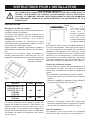 7
7
-
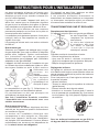 8
8
-
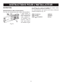 9
9
-
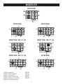 10
10
-
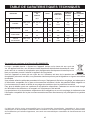 11
11
-
 12
12
-
 13
13
-
 14
14
-
 15
15
-
 16
16
-
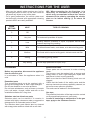 17
17
-
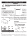 18
18
-
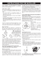 19
19
-
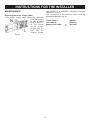 20
20
-
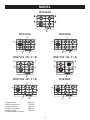 21
21
-
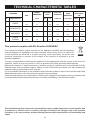 22
22
-
 23
23
-
 24
24
-
 25
25
-
 26
26
-
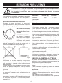 27
27
-
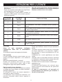 28
28
-
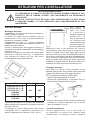 29
29
-
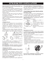 30
30
-
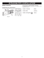 31
31
-
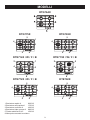 32
32
-
 33
33
-
 34
34
-
 35
35
-
 36
36
-
 37
37
-
 38
38
-
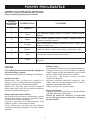 39
39
-
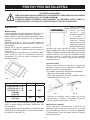 40
40
-
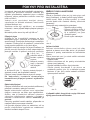 41
41
-
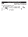 42
42
-
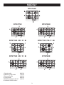 43
43
-
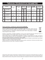 44
44
-
 45
45
-
 46
46
-
 47
47
-
 48
48
-
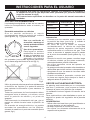 49
49
-
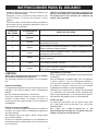 50
50
-
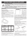 51
51
-
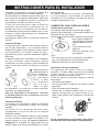 52
52
-
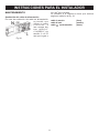 53
53
-
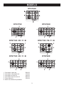 54
54
-
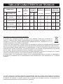 55
55
-
 56
56
-
 57
57
-
 58
58
-
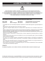 59
59
-
 60
60
-
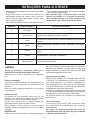 61
61
-
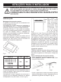 62
62
-
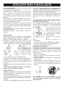 63
63
-
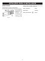 64
64
-
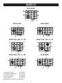 65
65
-
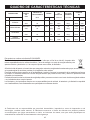 66
66
-
 67
67
-
 68
68
-
 69
69
-
 70
70
-
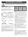 71
71
-
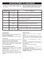 72
72
-
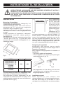 73
73
-
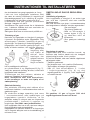 74
74
-
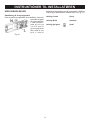 75
75
-
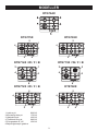 76
76
-
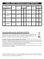 77
77
-
 78
78
-
 79
79
-
 80
80
-
 81
81
-
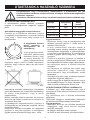 82
82
-
 83
83
-
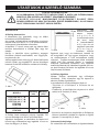 84
84
-
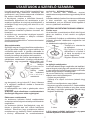 85
85
-
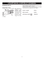 86
86
-
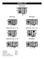 87
87
-
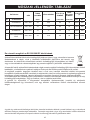 88
88
-
 89
89
-
 90
90
-
 91
91
-
 92
92


DeDietrich DTG764X El manual del propietario
- Tipo
- El manual del propietario
en otros idiomas
- français: DeDietrich DTG764X Le manuel du propriétaire
- italiano: DeDietrich DTG764X Manuale del proprietario
- English: DeDietrich DTG764X Owner's manual
- português: DeDietrich DTG764X Manual do proprietário
- slovenčina: DeDietrich DTG764X Návod na obsluhu
- dansk: DeDietrich DTG764X Brugervejledning