Black Box LPJ008A-T-R2 Manual de usuario
- Categoría
- Conmutadores de red
- Tipo
- Manual de usuario
Este manual también es adecuado para

24/7 TECHNICAL SUPPORT AT 1.877.877.2269 OR VISIT BLACKBOX.COM
8- OR 16-PORT
10/100/1000
POE INJECTOR
LPJ008A-T-R2, L PJ016A-T-R2
USER MANUAL
2
1
3
4
POWER
POWER + DATA (OUT)
DATA (IN)
PDLINK
2
3
4
56
7
8
1
6
7
8
5

2
TABLE OF CONTENTS
NEED HELP?
LEAVE THE TECH TO US
LIVE 24/7
TECHNICAL
SUPPORT
1.8 77.87 7. 2269
1. 8 7 7. 8 7 7. 2 2 6 9 BLACKBOX.COM
1. SPECIFICATIONS ........................................................................................................................................................................... 3
2. OVERVIEW ...................................................................................................................................................................................... 4
2.1 Introduction ...............................................................................................................................................................................................4
2.2 Features ....................................................................................................................................................................................................4
2.3 What’s Included ........................................................................................................................................................................................ 4
2.4 Hardware Description .............................................................................................................................................................................. 5
2.4.1 LPJ008A-T-R2 .....................................................................................................................................................................................................5
2.4.2 LPJ016A-T-R2 .....................................................................................................................................................................................................6
2.4.3 LED Indicators ....................................................................................................................................................................................................7
3. CONNECTIONS .............................................................................................................................................................................. 8
Connecting a Powered Device/Existing Switch to a Power Injector .........................................................................................................8
APPENDIX A. REGULATORY INFORMATION .................................................................................................................................. 9
A.1 FCC Statement .........................................................................................................................................................................................9
A.2 NOM Statement .....................................................................................................................................................................................10
APPENDIX B. DISCLAIMER/TRADEMARKS ................................................................................................................................. 11
B.1 Disclaimer ............................................................................................................................................................................................... 11
B.2 Trademarks Used in this Manual .......................................................................................................................................................... 11

3
1. 8 7 7. 8 7 7. 2 2 6 9 BLACKBOX.COM
NEED HELP?
LEAVE THE TECH TO US
LIVE 24/7
TECHNICAL
SUPPORT
1.8 77.87 7. 2269
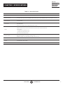
CHAPTER 1: SPECIFICATIONS
TABLE 1-1. SPECIFICATIONS
SPECIFICATION DESCRIPTION
Standards IEEE 802.3af, IEEE 802.3at, IEEE 802.3 10BASE-T, IEEE 802.3u 100BASE-TX, IEEE 802.3ab 1000BASE-T
Number of Ports
LPJ008A-T-R2: (8) 10/100/1000BASE-T data-in ports, (8) 10/100/1000BASE-T data-out and power-out ports;
LPJ016A-T-R2: (16) 10/100/1000BASE-T data-in ports, (16) 10/100/1000BASE-T data-out and power-out ports
LED Indicators
Per Port: PD Link, Link ACT/Speed,
Per Unit: Power
L2 Features
Auto-negotiation,
Auto MDI/MDI-X,
Flow Control (duplex): 802.3x (Full), Backpressure (Half)
Power
Input: 100 to 240 VAC, 50 to 60 Hz;
Output: 56 VDC per port output, 30 W maximum per port, 8 or 16 ports at full 30 W;
Consumption:
LPJ008A-T-R2: 250 Watts (max.),
LPJ016A-T-R2: 500 Watts (max.),
PoE standards: IEEE 802.3af/at
Environmental
Operating Temperature: 32 to 104° F (0 to 40° C);
Storage Temperature: -4 to +194° F (-20 to +90° C);
Relative Humidity: 10 to 90% relative humidity, noncondensing;
Dimensions 1.7" H x 17.3" W x 8.7" D (4.4 x 44 x 22 cm)
Weight
LPJ008A-T-R2: 5.9 lb. (2.7 kg),
LPJ016A-T-R2: 7.0 lb. (3.2 kg)
Certifications FCC Class A, CE

4
1. 8 7 7. 8 7 7. 2 2 6 9 BLACKBOX.COM
NEED HELP?
LEAVE THE TECH TO US
LIVE 24/7
TECHNICAL
SUPPORT
1.8 77.87 7. 2269
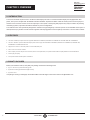
CHAPTER 2: OVERVIEW
2.1 INTRODUCTION
The 10/100/1000 PoE Injector has 8 or 16 Ethernet data input ports and 8 or 16 Ethernet data output ports equipped with 48-V
power, The injector complies with the IEEE 802.3af PoE standard. Any Ethernet “Data” cable can directly connect to the input port
and then come out “Data + Power” from the output port. The injector is smart plug-and-play and very easy to install in any existing
networking system, to provide PoE features without any new reconfiguration.
The rackmount size was specifically designed for medium to large workgroups. The PoE Injector can be installed where space is
limited; moreover, it provides smooth network migration and easy upgrade to network capacity. It mounts in a 19-inch rack or cabinet.
2.2 FEATURES
Has 8 or 16 data input ports that comply with IEEE 802.3 10BASE-T, IEEE 802.3u 100BASE-TX and IEEE 802.3ab 1000BASE-T
Has 8 or 16 data + power PSE/PoE output ports that comply with IEEE 802.3 10BASE-T, IEEE 802.3u 100BASE-TX, IEEE 802.3ab,
1000BASE-T and IEEE 802.3at PoE
Supports a maximum of 30 W power for each PSE/PoE port
Fits in a 19-inch rack or cabinet
Each output port has output current limited, short-circuit protection, complete Powered Device (PD) detection and classification
Smart plug-and-play
Front-panel LEDs indicate power and status
2.3 WHAT’S INCLUDED
Before you install this switch, verify that your package contains the following items:
(1) 8- or 16-Port 10/100/1000 PoE Injector
(1) Rackmount kit ([2] brackets and [8] screws)
(1) Power cord
If anything is missing or damaged, contact Black Box Technical Support at 877-877-2269 or info@blackbox.com.

5
1. 8 7 7. 8 7 7. 2 2 6 9 BLACKBOX.COM
NEED HELP?
LEAVE THE TECH TO US
LIVE 24/7
TECHNICAL
SUPPORT
1.8 77.87 7. 2269
CHAPTER 2: OVERVIEW
2.4 HARDWARE DESCRIPTION
2.4.1 LPJ008A-T-R2
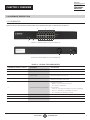
Figures 2-1 and 2-2 show the front and back panels of the LPJ008A-T-R2. Table 2-1 describes its components.
1
2
3
4
5
5
FIGURE 2-1. FRONT PANEL OF THE LPJ008A-T-R2
6 7 8
FIGURE 2-2. BACK PANEL OF THE LPJ008A-T-R2
TABLE 2-1. LPJ008A-T-R2 COMPONENTS
NUMBER IN FIGURES 2-1 AND 2-2 COMPONENT DESCRIPTION
1 (8) RJ-45 ports Data input ports
2 (8) RJ-45 PoE ports Data and power output ports
3 (1) Power LED
ON when power to the unit is on,
OFF when power to the unit is off
4 (8) PD Link LEDs
ON when providing PoE power to a device;
OFF when not providing PoE Power
5 (16) Link/ACT LEDs/(16) Speed LEDs
Link/Activity indicator:
Blinking – There is activity on this port
Off – No link is established
Speed indicator:
Amber on – Operating as a Gigabit connection (1000 Mbps)
Green on – Operating as a 100-Mbps connection
Off – Operating as a 10-Mbps connection
6 (1) fan Prevents the switch from overheating
7 (1) power ON/OFF switch Press to switch the unit on or off (I or O)
8 (1) power connector Links to 90 to 260 VAC power

6
1. 8 7 7. 8 7 7. 2 2 6 9 BLACKBOX.COM
NEED HELP?
LEAVE THE TECH TO US
LIVE 24/7
TECHNICAL
SUPPORT
1.8 77.87 7. 2269
CHAPTER 2: OVERVIEW
2.4.2 LPJ016A-T-R2
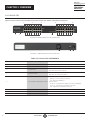
Figures 2-3 and 2-4 show the front and back panels of the LPJ016A-T-R2. Table 2-2 describes its components.
1
1
2
2
5
5
55
3 4
4
FIGURE 2-3. FRONT PANEL OF THE LPJ016A-T-R2
6 7 8
FIGURE 2-4. BACK PANEL OF THE LPJ016A-T-R2
TABLE 2-2. LPJ016A-T-R2 COMPONENTS
NUMBER IN FIGURES 2-3 AND 2-4 COMPONENT DESCRIPTION
1 (16) RJ-45 ports Data input ports
2 (16) RJ-45 PoE ports Data and power output ports
3 (1) Power LED
ON when power to the unit is on,
OFF when power to the unit is off
4 (16) PD Link LEDs
ON when providing PoE power to a device;
OFF when not providing PoE Power
5 (32) Link/ACT LEDs/(32) Speed LEDs
Link/Activity indicator:
Blinking – There is activity on this port
Off – No link is established
Speed indicator:
Amber on – Operating as a Gigabit connection (1000 Mbps)
Green on – Operating as a 100-Mbps connection
Off – Operating as a 10-Mbps connection
6 (1) fan Prevents the switch from overheating
7 (1) power ON/OFF switch Press to switch the unit on or off (I or O)
8 (1) power connector Links to 90 to 260 VAC power

7
1. 8 7 7. 8 7 7. 2 2 6 9 BLACKBOX.COM
NEED HELP?
LEAVE THE TECH TO US
LIVE 24/7
TECHNICAL
SUPPORT
1.8 77.87 7. 2269
CHAPTER 2: OVERVIEW
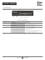
2.4.3 LED INDICATORS
1
2
3
3
FIGURE 2-5. LEDS ON THE INJECTOR
TABLE 2-3. LED INDICATORS
NUMBER IN FIGURE 2-5 COMPONENT DESCRIPTION
1 (1) Power LED
ON when power to the unit is on,
OFF when power to the unit is off
2 (8) or (16) PD Link LEDs
ON when providing PoE power to a device;
OFF when not providing PoE Power
3 (16) or (32) Link/ACT LEDs/(16) or (32) Speed LEDs
Link/Activity indicator:
Blinking – There is activity on this port
Off – No link is established
Speed indicator:
Amber on – Operating as a Gigabit connection (1000 Mbps)
Green on – Operating as a 100-Mbps connection
Off – Operating as a 10-Mbps connection

8
1. 8 7 7. 8 7 7. 2 2 6 9 BLACKBOX.COM
NEED HELP?
LEAVE THE TECH TO US
LIVE 24/7
TECHNICAL
SUPPORT
1.8 77.87 7. 2269
CHAPTER 3: CONNECTIONS
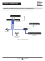
CONNECTING A POWERED DEVICE/EXISTING SWITCH TO A POWER INJECTOR
Use CAT5 twisted-pair cable from the existing switch to the “Data” input port of the power injector, and then connect the “Data +
Power” output port to the Powered Device, such as Wireless AP, another switch with PD function, etc.
IP Camera
with PoE support
Wireless Access Point
with PoE support
Terminal Server
(no PoE support)
PoE Splitter
10/100/1000 PoE Injector
with (8) PSE ports
PoE Switch
Existing 10/100
Ethernet Switch
FIGURE 3-1. CONNECTION DIAGRAM-

9
1. 8 7 7. 8 7 7. 2 2 6 9 BLACKBOX.COM
NEED HELP?
LEAVE THE TECH TO US
LIVE 24/7
TECHNICAL
SUPPORT
1.8 77.87 7. 2269
APPENDIX A: REGULATORY INFORMATION
A.1 FCC CLASS A STATEMENT
This equipment generates, uses, and can radiate radio-frequency energy, and if not installed and used properly, that is, in strict
accordance with the manufacturer’s instructions, may cause interference to radio communication. It has been tested and found to
comply with the limits for a Class A computing device in accordance with the specifications in Subpart B of Part 15 of FCC rules,
which are designed to provide reasonable protection against such interference when the equipment is operated in a commercial
environment. Operation of this equipment in a residential area is likely to cause interference, in which case the user at his own
expense will be required to take whatever measures may be necessary to correct the interference.
Changes or modifications not expressly approved by the party responsible for compliance could void the user’s authority to
operate the equipment.
This digital apparatus does not exceed the Class A limits for radio noise emission from digital apparatus set out in the Radio
Interference Regulation of Industry Canada.
Le présent appareil numérique n’émet pas de bruits radioélectriques dépassant les limites applicables aux appareils numériques
de la classe A prescrites dans le Règlement sur le brouillage radioélectrique publié par Industrie Canada.

10
1. 8 7 7. 8 7 7. 2 2 6 9 BLACKBOX.COM
NEED HELP?
LEAVE THE TECH TO US
LIVE 24/7
TECHNICAL
SUPPORT
1.8 77.87 7. 2269
APPENDIX A: REGULATORY INFORMATION
A.2 NOM STATEMENT
1. Todas las instrucciones de seguridad y operación deberán ser leídas antes de que el aparato eléctrico sea operado.
2. Las instrucciones de seguridad y operación deberán ser guardadas para referencia futura.
3. Todas las advertencias en el aparato eléctrico y en sus instrucciones de operación deben ser respetadas.
4. Todas las instrucciones de operación y uso deben ser seguidas.
5. El aparato eléctrico no deberá ser usado cerca del agua—por ejemplo, cerca de la tina de baño, lavabo, sótano mojado o cerca de
una alberca, etc.
6. El aparato eléctrico debe ser usado únicamente con carritos o pedestales que sean recomendados por el fabricante.
7. El aparato eléctrico debe ser montado a la pared o al techo sólo como sea recomendado por el fabricante.
8. Servicio—El usuario no debe intentar dar servicio al equipo eléctrico más allá a lo descrito en las instrucciones de operación.
Todo otro servicio deberá ser referido a personal de servicio calificado.
9. El aparato eléctrico debe ser situado de tal manera que su posición no interfiera su uso. La colocación del aparato eléctrico
sobre una cama, sofá, alfombra o superficie similar puede bloquea la ventilación, no se debe colocar en libreros o gabinetes que
impidan el flujo de aire por los orificios de ventilación.
10. El equipo eléctrico deber ser situado fuera del alcance de fuentes de calor como radiadores, registros de calor, estufas u otros
aparatos (incluyendo amplificadores) que producen calor.
11. El aparato eléctrico deberá ser connectado a una fuente de poder sólo del tipo descrito en el instructivo de operación, o como
se indique en el aparato.
12. Precaución debe ser tomada de tal manera que la tierra fisica y la polarización del equipo no sea eliminada.
13. Los cables de la fuente de poder deben ser guiados de tal manera que no sean pisados ni pellizcados por objetos colocados
sobre o contra ellos, poniendo particular atención a los contactos y receptáculos donde salen del aparato.
14. El equipo eléctrico debe ser limpiado únicamente de acuerdo a las recomendaciones del fabricante.
15. En caso de existir, una antena externa deberá ser localizada lejos de las lineas de energia.
16. El cable de corriente deberá ser desconectado del cuando el equipo no sea usado por un largo periodo de tiempo.
17. Cuidado debe ser tomado de tal manera que objectos liquidos no sean derramados sobre la cubierta u orificios de ventilación.
18. Servicio por personal calificado deberá ser provisto cuando:
A: El cable de poder o el contacto ha sido dañado; u
B: Objectos han caído o líquido ha sido derramado dentro del aparato;o
C: El aparato ha sido expuesto a la lluvia; o
D: El aparato parece no operar normalmente o muestra un cambio en su desempeño; o
E: El aparato ha sido tirado o su cubierta ha sido dañada.

11
1. 8 7 7. 8 7 7. 2 2 6 9 BLACKBOX.COM
NEED HELP?
LEAVE THE TECH TO US
LIVE 24/7
TECHNICAL
SUPPORT
1.8 77.87 7. 2269
APPENDIX B: DISCLAIMER/TRADEMARKS
B.1 DISCLAIMER
Black Box Corporation shall not be liable for damages of any kind, including, but not limited to, punitive, consequential or cost of cover
damages, resulting from any errors in the product information or specifications set forth in this document and Black Box Corporation
may revise this document at any time without notice.
B.2 TRADEMARKS USED IN THIS MANUAL
Black Box and the Black Box logo type and mark are registered trademarks of Black Box Corporation.
Any other trademarks mentioned in this manual are acknowledged to be the property of the trademark owners.

NEED HELP?
LEAVE THE TECH TO US
LIVE 24/7
TECHNICAL
SUPPORT
1.87 7.877. 2269
© COPYRIGHT 2019. BLACK BOX CORPORATION. ALL RIGHTS RESERVED.
LPJ008A-T-R2_USER_REV1.PDF
-
 1
1
-
 2
2
-
 3
3
-
 4
4
-
 5
5
-
 6
6
-
 7
7
-
 8
8
-
 9
9
-
 10
10
-
 11
11
-
 12
12


Black Box LPJ008A-T-R2 Manual de usuario
- Categoría
- Conmutadores de red
- Tipo
- Manual de usuario
- Este manual también es adecuado para
en otros idiomas
- English: Black Box LPJ008A-T-R2 User manual
Artículos relacionados
-
Black Box LPR1111 Manual de usuario
-
Black Box WMD-1075FAN-U El manual del propietario
-
-
-
Black Box 4KDPKVMXT-100M Manual de usuario
-
Blackbox KVXLC-100, KVXLCF-100 Manual de usuario
-
Black Box LH1690C-LC-R3 El manual del propietario
-
-
-