Bosch ES4 Instrucciones de operación
- Categoría
- Calentadores de agua
- Tipo
- Instrucciones de operación
Este manual también es adecuado para

Use this manual for installations in the United States of America:
Utilice este manual para las instalaciones en los Estados Unidos de América:
[3] Installation Manual and Operating Instructions
[14] Instrucciones de Instalación y Funcionamiento
Tronic 3000T
ES 2.5/4/8...
6 720 801 072 (2015/02) US

2 | Table of contents
Tronic 3000T6 720 801 072 (2015/02)
Table of contents
1 Explanation of symbols and safety information . . . . . . . . . . . . 3
1.1 Key to symbols . . . . . . . . . . . . . . . . . . . . . . . . . . . . . . . . . 3
1.2 Safety information . . . . . . . . . . . . . . . . . . . . . . . . . . . . . . . 3
2 Information about the product . . . . . . . . . . . . . . . . . . . . . . . . . . 4
2.1 Models overview . . . . . . . . . . . . . . . . . . . . . . . . . . . . . . . . 4
2.2 Dimensions . . . . . . . . . . . . . . . . . . . . . . . . . . . . . . . . . . . . 5
2.3 Technical data . . . . . . . . . . . . . . . . . . . . . . . . . . . . . . . . . . 6
3 Installation instructions . . . . . . . . . . . . . . . . . . . . . . . . . . . . . . . . 7
3.1 Mounting the heater . . . . . . . . . . . . . . . . . . . . . . . . . . . . . 7
3.2 Pipe connections . . . . . . . . . . . . . . . . . . . . . . . . . . . . . . . . 7
3.3 Closed system thermal expansion . . . . . . . . . . . . . . . . . . 7
3.4 Electrical connections . . . . . . . . . . . . . . . . . . . . . . . . . . . . 8
4 Use . . . . . . . . . . . . . . . . . . . . . . . . . . . . . . . . . . . . . . . . . . . . . . . . . . 8
4.1 Starting and testing . . . . . . . . . . . . . . . . . . . . . . . . . . . . . . 8
4.2 Temperature setting . . . . . . . . . . . . . . . . . . . . . . . . . . . . . 8
5 Maintenance . . . . . . . . . . . . . . . . . . . . . . . . . . . . . . . . . . . . . . . . . 9
5.1 Removing the cover . . . . . . . . . . . . . . . . . . . . . . . . . . . . . . 9
5.2 Draining the heater . . . . . . . . . . . . . . . . . . . . . . . . . . . . . . 9
5.3 Inspecting the anode rod . . . . . . . . . . . . . . . . . . . . . . . . . 9
5.4 Removing the heating element . . . . . . . . . . . . . . . . . . . . . 9
5.5 Descaling the heating element . . . . . . . . . . . . . . . . . . . 10
6 Replacement of parts . . . . . . . . . . . . . . . . . . . . . . . . . . . . . . . . 10
6.1 Changing the anode rod . . . . . . . . . . . . . . . . . . . . . . . . 10
6.2 Changing the heating element . . . . . . . . . . . . . . . . . . . 10
6.3 Changing the thermostat . . . . . . . . . . . . . . . . . . . . . . . 10
7 Troubleshooting . . . . . . . . . . . . . . . . . . . . . . . . . . . . . . . . . . . . 11
7.1 Resetting High Limit Switch . . . . . . . . . . . . . . . . . . . . . 11
8 Bosch interior components diagram . . . . . . . . . . . . . . . . . . . 12
9 Bosch Tronic 3000T
LIMITED WARRANTY . . . . . . . . . . . . . . . . . . . . . . . . . . . . . . . . . 13

Explanation of symbols and safety information | 3
6 720 801 072 (2015/02)Tronic 3000T
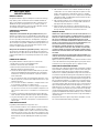
1 Explanation of symbols and safety
information
1.1 Key to symbols
Warnings
The following keywords are defined and can be used in this document:
• NOTICE indicates that damage to property may occur.
• CAUTION indicates that personal injury may occur.
• WARNING indicates that severe personal injury may occur.
• DANGER indicates that severe personal injury or death may occur.
Important information
Additional symbols
1.2 Safety information
▶ READ ALL INSTRUCTIONS BEFORE USING THIS WATER HEATER.
▶ This water heater must be grounded. Connect only to properly
grounded outlet. See “GROUNDING INSTRUCTIONS” found on
“INSTALLATION INSTRUCTIONS”.
▶ Install or locate this water heater only in accordance with the
provided installation instructions.
▶ Use this water heater only for its intended use as described in this
manual.
▶ The models ES2.5 and ES4 come equipped with a power cord. Do
not use an extension cord. If no outlet is available adjacent to the
water heater, contact a qualified electrician to have one properly
installed near the heater. The model ES8 must be hard-wired. See
installation instructions.
▶ As with any appliance, close supervision is necessary when used by
children.
▶ Do not operate this water heater if it is has a damaged cord or plug, if
it is not working properly, or if it has been damaged or dropped.
▶ This water heater should be serviced only by qualified service
personnel. Contact a service person for examination, repair or
adjustment.
▶ Failure to inspect the anode rod at least once a year could cause the
tank to fail and leak. This condition is not covered under the
manufacturer's warranty.
▶ Any water heater should be installed in such a manner that if it should
leak, the resulting flow of water will not cause damage to the area in
which it is installed. National Plumbing codes require a drain pan for
any water heater installation. Failure to install one is the sole
responsibility of owner and/or installer. Reference UPC 2006
(Uniform Plumbing Code) Section 508.1, or IPC 2006 (International
Plumbing Code) Section 504.7.
Warnings in this document are identified by a warning
triangle printed against a grey background.
Keywords at the start of a warning indicate the type and
seriousness of the ensuing risk if measures to prevent
the risk are not taken.
This symbol indicates important information where
there is no risk to people or property.
Symbol Explanation
▶ Step in an action sequence
Cross-reference to another part of the document
• List entry
– List entry (second level)
Table 1
CAUTION:
When using electrical appliances, safety precautions to
reduce the risk of fire, electric shock or injury to persons
should be followed, including:
NOTICE:
The installer should review the contents of this manual
with the owner upon completion of installation, and the
manual should be left with the owner and placed in a
location close to the installation.
NOTICE:
The manufacturer cannot be responsible for the
damages caused by improper installation or by failure to
follow instructions in this manual. Comply with the
installation instructions before completing electric
connection.
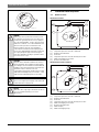
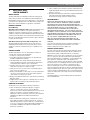
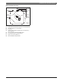
NOTICE:
The thermostat has been pre-set at the factory at a
temperature equal or below 51.7 °C (125 °F) (
Fig. 1).

4 | Information about the product
Tronic 3000T6 720 801 072 (2015/02)
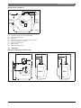
Fig. 1
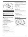
2 Information about the product
2.1 Models overview
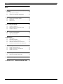
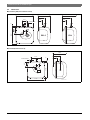
Models ES2.5 and ES4
Fig. 2
[1] Temperature & pressure relief valve, ¾ NPT male
[2] Cold water inlet ½ NPT male
[3] Thermostat
[4] Temperature & pressure relief valve discharge line to drain
[5] ¾ NPT female tapping for relief valve
[6] Hot water outlet ½ NPT male
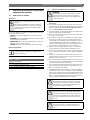
Models ES8 (Horizontal installation)
Fig. 3
[1] Temperature & pressure relief valve, ¾ NPT male
[2] Cold water inlet ¾ NPT male
[3] Thermostat
[4] Temperature & pressure relief valve discharge line to drain
[5] ¾ NPT female tapping for relief valve
[6] Hot water outlet ¾ NPT male
[7] ¾ NPT male plug
[8] ¾ NPT female tapping for tap
DANGER:
Hydrogen gas can be produced in a hot water system
served by this heater that has not been used for a long
period of time (generally 2 weeks or more). Hydrogen
gas is extremely flammable. To reduce the risk of injury
under these conditions, it is recommended that the hot
water faucet be opened for several minutes at the
kitchen sink before using any electrical appliance
connected to the hot water system. If hydrogen gas is
present, there will probably be an unusual sound such as
air escaping through the pipe as the water begins to
flow. There should be no smoking or open flame near the
faucet at the time it is open.
CAUTION:
Any water heater should be installed in such a manner
that if it should leak, the resulting flow of water will not
cause damage to the area in which it is installed. National
Plumbing codes require a drain pan for any water heater
installation. Failure to install one is the sole
responsibility of owner and/or installer. Reference UPC
2006 (Uniform Plumbing Code) Section 508.1, or IPC
2006 (International Plumbing Code) Section 504.7.
CAUTION:
Prior to connecting the power supply, ensure tank is full
of water and system is purged of air.
NOTICE:
Tank failure due to neglecting to maintain the anode rod
is not covered under warranty (see Section 5
Maintenance).
MAX
MIN
OFF
IDEAL
6720801072-07.1V
1
MAX
M
IN
O
F
F
ID
E
A
L
2
4
5
6
3
6720801072-01.1V
1
MAX
M
IN
O
F
F
ID
E
A
L
2
4
5
3
6720801072-02.1V
6
7
8

Information about the product | 5
6 720 801 072 (2015/02)Tronic 3000T
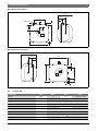
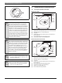
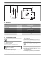
Models ES8 (Vertical installation)
Fig. 4
[1] Temperature & pressure relief valve, ¾ NPT male
[2] Cold water inlet ¾ NPT male
[3] Thermostat
[4] Temperature & pressure relief valve discharge line to drain
[5] ¾ NPT female tapping for relief valve
[6] Hot water outlet ¾ NPT male
[7] ¾ NPT male plug
[8] ¾ NPT female tapping for tap
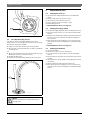
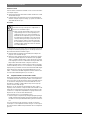
2.2 Dimensions
Models ES2.5 and ES4 (Vertical installation only)
Fig. 5
1
2
4
5
3
6720801072-03.1V
6
7
8
M
IN
O
F
F
M
A
X
IDEAL
10 ¾”
6¼”
3½”
13 ½”
9”
3½”
2½”2 ½”
3¾”
13 ¾”
½ NPT male
13 ¾”
5”
3
8
1”
6720801072-04.1V
ES2.5 ES4

6 | Information about the product
Tronic 3000T6 720 801 072 (2015/02)
Models ES8 (Vertical installation)
Fig. 6
Models ES8 (Horizontal installation)
Fig. 7
2.3 Technical data
Technical data Units ES 2.5 ES 4 ES 8
Capacity gallons 2.7 4.0 7.0 (Vert) / 5.1 (Hor)
Voltage VAC 110/120 for each model
Power at 120 VAC Watts 1440
Maximum water pressure psi 150
Weight (empty) Lbs 15.5 17.3 29.5
Amperage Amps
12.0 for each model
Phases
1
Temperature range °F
65 - 145
Recovery rate gallons/hour
6.8
Table 2
14 ½”
4½”
8½”
6720801072-06.1V
17.6”
M
IN
O
F
F
M
A
X
ID
E
A
L
17.6”
1”
11.4”
¾ NPT MALE
2½”
6½”
14 ½”
4½”
8½”
17.6”
17.6”
6720801072-05.1V
MAX
M
IN
O
F
F
ID
E
A
L
3”
11.4”
¾ NPT MALE”
1”

Installation instructions | 7
6 720 801 072 (2015/02)Tronic 3000T
3 Installation instructions
3.1 Mounting the heater
3.1.1 Wall mounting
▶ Fasten the supplied mounting bracket to the wall.
▶ Hang the water heater on the bracket.
▶ Tug down wards on the heater to ensure that both “fingers”of the
bracket are seated in the mounting slots.
3.1.2 Floor mounting
▶ Heater can sit on floor.
3.2 Pipe connections
▶ Connect the cold water inlet pipe to the inlet tapping (marked with a
blue ring).
▶ Ensure a isolation valve is installed on the cold water supply to the
water heater.
▶ Connect the hot water outlet pipe to the outlet tapping (marked with
a red ring).
Horizontal installation - ES8 Model Only
If you wish to install the unit horizontally, with the piping connections on
the right side:
▶ Install supplied brass plug into tap between hot and cold water
connections.
▶ The supplied Temperature and Pressure Relief Valve will need to be
installed on top. See location of T&P relief valve in Fig. 7.
Vertical installation
If you wish to install the unit vertically, with the piping connections on
top:
▶ Install supplied brass plug into tap on side of water heater.
▶ The supplied Temperature and Pressure Relief Valve will need to be
installed on top. See location of T&P relief valve in Fig. 5 and 6.
Caution
The supplied temperature and pressure relief valve is marked with a
maximum set pressure (150 psi) that does not exceed the marked
maximum working pressure of the water heater.
▶ Install the valve in the opening provided and marked for this purpose
in the water heater.
▶ Orient it or provide tubing so that any discharge from the valve will
exit within 6 inches above, or at any distance below, the structural
floor, and cannot contact any live electrical part. The discharge
opening must not be blocked or reduced in size under any
circumstances.
National Plumbing codes may require a drain pan for the water heater
installation. Failure to install one is the sole responsibility of owner and/
or installer. Reference UPC (Uniform Plumbing Code), or IPC
(International Plumbing Code).
3.3 Closed system thermal expansion
Periodic discharge of the temperature and pressure relief valve or failure
of the element gasket may be due to thermal expansion in a closed water
supply system. The water utility supply meter may contain a checkvalve,
backflow preventer or waterpressure reducing valve which will create a
closed water system.
During the heating cycle of the water heater, the water expands causing
pressure inside the water heater to increase. The temperature and
pressure relief valve may discharge hot water under these conditions
which results in a loss of energy and a build-up of lime on the relief valve
seat.
To prevent this from happening, there are two recommendations:
1. Install a diaphragm-type expansion tank that is suitable for potable
water on the cold water supply line. A minimum 0.5 gallon expansion
tank should be used.
Contact the local water supplier or plumbing inspector for information
on how to control this situation. Do not plug the temperature and
pressure relief valve.
The ES2.5 and ES4 water heaters are designed to be
installed under the sink.
NOTICE: Material damages!
Use screws that are suitable for the wall material and the
weight of the heater.
The model ES8 can be piped horizontally from the side or
vertically from the top.
CAUTION:
To reduce the risk of excessive pressures and
temperatures in this water heater:
▶ Install the supplied temperature and pressure
protective equipment required by local codes but not
less than a combination temperature and pressure
relief valve certified by a nationally recognized
testing laboratory that maintains periodic inspection
of production of listed equipment or materials, as
meeting the requirements for Relief Valves and
Automatic Gas Shut-off Devices for Hot Water
Supply Systems, ANSIZ21.22.

8 | Use
Tronic 3000T6 720 801 072 (2015/02)
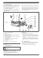
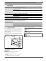
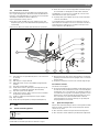
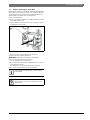
3.4 Electrical connections
The ES8 model must be hard wired. As per the National Electric Code the
ES8 needs to be wired with 12 GA. wire to a 20 amp branch circuit.
▶ Unscrew the junction box cover and remove it.
▶ Insert 12 AWG through conduit into junction box and secure with
conduit strain relief (not supplied).
▶ Connect the wires and screw on the cover of the junction box.
▶ Make appropriate wiring connections to the water heater per the
National Electric Code.
The unit must be grounded with supplied grounding cable inside junction
box.
▶ Secure junction box cover once wiring connections have been made.
When the ES8 is not within sight of the electrical circuit breakers, a
circuit breaker lockout or additional local means of disconnection for all
non grounded conductors must be provided that is within sight of the
appliance. [REF NEC 422.31].
Fig. 8
[1] Cable housing (internal to the unit)
[2] Wiring
[3] Protection ring for wiring.
[4] Additional grounding cable AWG16 (minimum length 152mm)
[5] Junction box left cover
[6] Nº3 self tapping screw for junction box covers fixing (with lock
washer or serrated head)
[7] Junction box right cover
[8] Nº1 self tapping screw for grounding (with lock washer or
serrated head)
[9] Nº4 screws for junction box fixing
[10] Junction box
[11] Housing for junction box (in the plastic front cover)
4Use
4.1 Starting and testing
To fill the heater:
▶ Open supply valve for water heater to fill with water.
▶ Open hot water tap(s) supplied by the water heater to purge air out
of the system. Once air is purged, close hot water tap.
▶ Visually check for any leaks.
Turning heater on
For models which are not fitted with a switch:
▶ Supply power to the water heater by plugging in the power cord
(models ES2.5, ES4) or turning on the circuit breaker (model ES8).
If the light does not come on, turn the control knob in a clockwise
direction.
The light will come on until water temperature has reached the
thermostat temperature setting. The light will come back on any time
the water temperature inside the tank drops below the thermostat
setting.
4.2 Temperature setting
The temperature of the hot water is adjusted by rotating the knob M
(Fig. 9) located on the front cover. Temperature range is 65 - 145 °F.
▶ Turn the knob clockwise to increase temperature.
▶ Turn the knob counter-clockwise to decrease temperature.
1
2 3 4 5
6
7
8
9
10
11
6720801072-14.1V
CAUTION:
▶ DO NOT supply power to water heater until filled with
water.

Maintenance | 9
6 720 801 072 (2015/02)Tronic 3000T
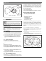
Fig. 9
5 Maintenance
Periodic maintenance
5.1 Removing the cover
▶ Pry off the round cover plate (Fig. 9, [V]) from its right hand edge
(Fig. 9, [W]) with a small flat-head screwdriver.
▶ Remove the Phillips screw revealed beneath the round cover plate.
▶ The cover (Fig. 9, [C]) can now be removed by pulling out its left-
hand edge. When reassembling, work in the opposite way being
careful to insert the tongue of the cover into the slot.
5.2 Draining the heater
If the heater has been installed with flexible hoses:
▶ Shut off the power supply.
▶ Turn the heater upside down over a sink to drain the water out of it.
-or-
it can also be emptied by:
▶ Siphon through the inlet side hose.
▶ Keep a hot water faucet open while siphoning.
-or-
If the heater has been installed with rigid piping:
▶ Siphon the water out through any (lower) service valve on the (inlet
side).
▶ Keep a hot water faucet open while siphoning the water out.
5.3 Inspecting the anode rod
The purpose of the anode rod (Fig. 12, [N]) is to protect the tank against
corrosion. It is critical that the anode rod be inspected once a year to
determine whether it requires replacement. To access the anode rod,
the heating element must be removed (see Section 5.4 Removing the
heating element). Upon inspection, the anode rod surface should
appear smooth. If the rod surface appears pitted, bumpy, rusty, or if the
rod is missing completely, then it must be replaced.
To access the anode rod:
▶ Remove the heating element (see Section 5.4 Removing the heating
element).
Original anode rod sizes
• ES2.5, ES4: length 6½ ”, diameter 5/8”
• ES8:length 8¼ ”, diameter 5/8”
Certain installations may require more frequent replacement of the
anode rod:
• recirculation applications;
• poor water quality;
• galvanic/electrolytic corrosion
• high flow applications
In the event of poor water quality, Bosch recommends consulting a local
water treatment professional for water treatment options. Always
ensure the water heater is grounded. Models ES2.5 and ES4 must be
connected only to a properly grounded outlet. Damage resulting from
poor water quality or failure to replace the anode rod is not covered
under the manufacturer’s warranty. For additional questions, please
call Bosch Technical Service.
5.4 Removing the heating element
▶ Turn off power supply and drain the heater (see previous section).
▶ Remove the front cover plate, disconnect terminals X, Y and T (Fig.
10).
▶ Unscrew the 4 heating element retaining nuts F (Fig. 10).
▶ Remove thermostat temperature sensor from well [B] located on the
element assembly (Fig. 10).
▶ Remove the element G (Fig. 11).
Fig. 10
CAUTION:
Do not attempt to repair this water heater yourself. Call
a service person for assistance. Always turn off the
power supply to the heater prior to servicing or draining
the heater.
For most of these operations, the water will have to be
drained from the heater. For all of these operations the
cord should be disconnected (ES2.5 and ES4 only) and
the front cover removed.
MAX
MIN
OFF
IDEAL
V W
C
M
6720801072-08.1V
6720801072-09.1V
G
Z
F
X
Y
T
A
E
H
B

10 | Replacement of parts
Tronic 3000T6 720 801 072 (2015/02)
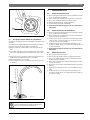
Fig. 11
5.5 Descaling the heating element
Scale deposits can affect the heating capability of the element.
Heavy scale can even cause damage to the element. The element can be
descaled either chemically or manually:
▶ Soak the element in white vinegar or other descaling solution.
▶ Once descaled, rinse well with fresh water, to which you should add
some baking soda,
-or-
▶ Once the element has dried, use a soft brush (non metallic to prevent
damaging the stainless steel sheath) on element.
▶ Brush the dried mineral off.
▶ Reinstall the element with gasket and make the wire connections.
Fig. 12
6 Replacement of parts
6.1 Changing the anode rod
▶ Turn off the power supply and drain the heater (see Draining the
Heater).
▶ Remove heating element (see previous section).
▶ Unscrew anode rod from threaded connection.
▶ Remove and replace the anode rod (Fig. 12, [N]).
▶ Reinstall heating element.
▶ Refill tank with water before restoring power.
6.2 Changing the heating element
▶ Turn off power supply and drain the heater (see Draining the Heater).
▶ Remove the heating element (see section on Removing the Heating
Element).
▶ Install new element with gasket, making sure the gasket and element
are positioned correctly. Tighten the retaining nuts and make the
wire connections.
▶ Ensure that the thermostat temperature sensor is inserted into the
well located on the element assembly and secured with black rubber
grommet.
▶ Refill tank with water before restoring power.
6.3 Changing the thermostat
▶ Turn off power supply.
▶ Disconnect the 2 wire connectors on thermostat.
▶ Loosen the two brass screws at right side of thermostat and pull
wires out.
▶ Remove thermostat temperature sensor from well located in element
assembly.
▶ Unscrew and remove the two Phillips screws holding the thermostat
onto the tank.
▶ Install new thermostat and re-attach wiring and screws.
▶ Ensure that the thermostat temperature sensor is inserted into the
well located on the element assembly and secured with black rubber
grommet.
NOTICE:
Make sure the tank has been refilled with water before
restoring power.
6720801072-10.1V
G
6720801072-11.1V
N

Troubleshooting | 11
6 720 801 072 (2015/02)Tronic 3000T
7 Troubleshooting
7.1 Resetting High Limit Switch
Occasionally, the high temperature limit shut off device may trip the
reset. This occurs when water temperature exceeds 190 °F. The shut off
device may also trigger from a power outage or electrical storm.
To reach the thermostat:
▶ Disconnect power cord (or shut off circuit breaker - model ES8) and
remove the front cover.
▶ Firmly press reset button (Fig. 13, [B]) with the tip of a ball point pen
or similar object.
Fig. 13
A click indicates the reset was tripped.
▶Reconnect power.
IMPORTANT: Check the operation of the thermostat:
▶ Turn temperature dial from high to low.
If the red light does not go off on low setting:
▶ Turn off power supply and call a service person to replace the
thermostat.
If the red light does go off the thermostat is working well:
▶ Place dial setting to desired setting.
▶ Replace cover plate.
Problem Solution
Water does not get hot. Make sure the power supply is on and working.
If light does not come on, check that the high limit reset button is pushed in;
follow steps in section 7.1.
If the indicator light works properly but temperature does not get hot at the tap, test for a plumbing crossover;
shut off cold supply to heater and open hot water tap. There should be no water flowing. Any continued flow
indicates a crossover which will effect the temperature and will need to be corrected.
Call a qualified service technician to test the resistance of the heating element (8-10 ohms). Heating element
should be replaced if readings are outside these values.
Light not on. If the light does not come on, but water gets hot, check for faulty bulb.
Check high limit reset button;
follow steps in section 7.1;
Brown water. Brown or rusty water indicates a “spent” anode rod and possible deterioration of the tank body.
Inspect the tank for leaks.
Check anode rod (see section on changing the anode rod).
Odor in water. Smelly water could be due to an unusual reaction between local water and the heater’s anode rod. Check anode
rod (see section on changing the anode rod).
Failure to do so may result in damage to the tank and leaks.
Leaking. Check water fittings and T & P fitting on top of tank.
Remove front cover and inspect heating element gasket.
If tank is leaking call Bosch Water Heating for warranty claim if still within warranty period.
Check anode rod (see section on changing the anode rod)
Table 3
6720801072-12.1V
A lower setting is more economical and reduces the risk
of scalding.
CAUTION:
Call a technician if the high limit needs to be reset
frequently.

12 | Bosch interior components diagram
Tronic 3000T6 720 801 072 (2015/02)
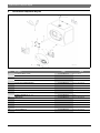
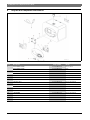
8 Bosch interior components diagram
Fig. 14
Part Description TTNR Model
1 HEATING ELEMENT 1440W 8 738 704 439 0 ES 2.5 / ES 4
HEATING ELEMENT 1440W
8 738 704 440 0 ES 8
3 WIRED THERMOSTAT 8 738 704 441 0 ES 2.5 / ES 4
WIRED THERMOSTAT
8 738 704 442 0 ES 8
7 HEATER WALL HANGING BRACKET 8 738 704 443 0 ES 2.5 / ES 4 / ES 8
14 PLASTIC COVER 8 738 704 446 0 ES 2.5 / ES 4 / ES 8
18 KNOB 8 738 704 444 0 ES 2.5 / ES 4 / ES 8
22 VALVE T&P ¾ 8 738 704 445 0 ES 2.5 / ES 4 / ES 8
23 MAGNESIUM ANODE D:14 L:155 M4 8 738 704 447 0 ES 2.5 / ES 4
MAGNESIUM ANODE D:16 L:195
8 738 704 448 0 ES 8
31 LOCK NUT M6 8 738 704 449 0 ES 2.5 / ES 4 / ES 8
33 GASKET WITH 4 BOLTS 8 738 704 450 0 ES 2.5 / ES 4 / ES 8
38 SIGNAL LAMP CAP 8 738 704 451 0 ES 2.5 / ES 4 / ES 8
44 CABLE CLAMP 8 738 704 452 0 ES 2.5 / ES 4 / ES 8
50 POWER CABLE 8 738 704 453 0 ES 2.5 / ES 4
70 LEVER THERMOSTAT 8 738 704 454 0 ES 2.5 / ES 4 / ES 8
Table 4
6720801072-13.1V

Bosch Tronic 3000T LIMITED WARRANTY | 13
6 720 801 072 (2015/02)Tronic 3000T
9 Bosch Tronic 3000T
LIMITED WARRANTY
MODELS COVERED
This limited warranty is provided by Bosch Thermotechnology Corp.
(“BTC”) and covers Bosch Tronic 3000T water heater Models ES2.5,
ES4 and ES8 (hereinafter referred to as “Water Heater”). This warranty
is provided to the original purchaser of the Water Heater as long as the
Water Heater remains installed at its original place of installation.
WARRANTY COVERAGE
Limited Warranty
Water Heater Inner Tank (“Inner Tank”) - BTC warrants that the Inner
Tank shall remain free of leaks for six (6) years from the date of
installation or from date of manufacture if proof of installation is not
available, provided it is properly installed and maintained and the other
conditions of this warranty are met. If BTC determines that the Product
has a defect in workmanship or materials, BTC, at its option, will repair
or replace the defective part.
Other Water Heater Components (“Other Components”) - BTC
warrants that Other Components will remain free from defects in
workmanship and materials for two (2) years from date of original
installation or from date of manufacture if proof of installation is not
available.
ITEMS NOT COVERED
This limited warranty does not cover the following circumstances:
1. Components or parts not provided by BTC.
2. Scratches in or discoloration of finishes.
3. Serviceable items and normal maintenance as required per the
Installation and Maintenance Manual.
4. The workmanship of any installer. BTC disclaims and does not
assume any liability of any nature for unsatisfactory performance
caused by improper installation, repair or maintenance.
5. Any labor or material costs for removal, reinstallation, repair and
replacement of the defective component or part.
6. Electricity or fuel costs, or any increases or unrealized savings in
same, for any reason whatsoever.
7. Damage caused by abuse, accident, neglect, excessive temperatures
or pressures, electrochemical reaction, water and air impurities,
electrical failures, flooding or acts of God.
8. Damage caused by lack of maintenance of anode rod. See Installation
Manual for details.
9. Shipping charges, delivery expenses or administrative fees incurred
by the purchaser in repairing or replacing the Water Heater.
CONDITIONS OF WARRANTY
The warranty herein is void under the following circumstances:
1. Failure or malfunction resulting from improper or negligent
operation, accident, abuse, freezing, electrical imbalance
characteristics, misuse, unauthorized alteration, incorrect electrical
supply, electrical surges, or improper installation, repair or
maintenance. Failure to maintain the anode rod. See the Installation
and Maintenance Manual for installation and maintenance
information.
2. Failure or malfunction resulting from a contaminated or corrosive
water supply, the addition of unapproved chemicals, operation at
abnormal temperatures, pressures or flow rates, or any attachment,
accessory or component not authorized and approved by BTC. See
the Installation and Maintenance Manual for installation and
maintenance information.
3. Failure or malfunction resulting from operation of Water Heater not
supplied with potable water or is operated with water that may cause
deposits or corrosion.
4. Work performed without prior authorization or approval and without
authorization/requisition number and without proper
documentation verifying compliance with above terms.
LIMITED WARRANTY
OTHER THAN THE OBLIGATIONS OF BTC EXPRESSLY SET FORTH
HERIN, BTC DISCLAIMS ALL WARRANTIES, EXPRESS OR IMPLIED,
INCLUDING BUT NOT LIMITED TO ANY IMPLIED WARRANTIES OF
MERCHANTABILITY OR FITNESS FOR A PARTICULAR PURPOSE. BTC’S
SOLE OBLIGATION WITH RESPECT TO THE PRODUCT AND
PURCHASER’S EXCLUSIVE REMEDIES ARE SET FORTH IN THE
FOREGOING LIMITED WARRANTY. BTC SHALL NOT BE LIABLE FOR
ANY INDIRECT, PUNITIVE, INCIDENTAL, SPECIAL, CONSEQUENTIAL OR
SIMILAR DAMAGES INCLUDING, WITHOUT LIMIITATION, INJURY OR
DAMAGE TO PERSONS OR PROPERTY OR DAMAGES FOR LOSS OF
USE, LOST PROFITS, INCONVENIENCE OR LOSS OF TIME.
NOTE THAT ANY REPAIRED OR REPLACED PRODUCT WILL BE
WARRANTED FOR ONLY THE UNEXPIRED TERM OF THE ORIGINAL
WARRANTY.
Some states do not allow the exclusion of limitation of damages, or
limitations on how long an implied warranty lasts, so the above
limitations and exclusions may not apply to you.
WARRANTY CLAIMS PROCESS
If you have a warranty claim you should notify the dealer who sold the
Water Heater or submit the warranty claim directly to BTC at Bosch
Thermotechnology Corp., 50 Wentworth Avenue, Londonderry,
NH 03053. To process your claim, you will need a copy of your original
invoice or other proof of purchase and documentation showing the
Water Heater Model number, Serial Number, original installation date,
place of purchase, and installer’s name. The alleged defective
components or parts must be returned to BTC in accordance with BTC
procedure then in force for handling goods returned for the purpose of
inspection to determine cause of failure (contact BTC if you have
questions regarding the return process). If BTC determines that the
returned components and/or parts are defective and that this warranty
applies, BTC will furnish the repaired or replacement components and/
or parts to an authorized BTC distributor who, in turn, will forward the
components and/or parts to the heating contractor who installed your
Water Heater.
This Warranty applies to Product installed in the Continental United
States and Canada only.

14 | Índice
Tronic 3000T6 720 801 072 (2015/02)
Índice
1 Explicación de los símbolos e instrucciones importantes de
seguridad . . . . . . . . . . . . . . . . . . . . . . . . . . . . . . . . . . . . . . . . . . . 15
1.1 Explicación de los símbolos . . . . . . . . . . . . . . . . . . . . . 15
1.2 Instrucciones importantes de seguridad . . . . . . . . . . . 15
2 Información sobre el calentador de agua . . . . . . . . . . . . . . . 16
2.1 Descripción general de los modelos . . . . . . . . . . . . . . 16
2.2 Dimensiones . . . . . . . . . . . . . . . . . . . . . . . . . . . . . . . . . 18
2.3 Datos técnicos . . . . . . . . . . . . . . . . . . . . . . . . . . . . . . . . 19
3 Instrucciones de instalación . . . . . . . . . . . . . . . . . . . . . . . . . . 19
3.1 Montaje del calentador . . . . . . . . . . . . . . . . . . . . . . . . . 19
3.2 Conexiones de tubería . . . . . . . . . . . . . . . . . . . . . . . . . 19
3.3 Expansión térmica en un sistema cerrado . . . . . . . . . . 20
3.4 Conexiones eléctricas . . . . . . . . . . . . . . . . . . . . . . . . . . 21
4 Uso . . . . . . . . . . . . . . . . . . . . . . . . . . . . . . . . . . . . . . . . . . . . . . . . 21
4.1 Puesta en marcha y pruebas . . . . . . . . . . . . . . . . . . . . . 21
4.2 Ajuste de la temperatura . . . . . . . . . . . . . . . . . . . . . . . . 21
5 Mantenimiento . . . . . . . . . . . . . . . . . . . . . . . . . . . . . . . . . . . . . 22
5.1 Quitar la tapa . . . . . . . . . . . . . . . . . . . . . . . . . . . . . . . . . 22
5.2 Drenado del calentador . . . . . . . . . . . . . . . . . . . . . . . . 22
5.3 Inspección de la barra del ánodo . . . . . . . . . . . . . . . . . 22
5.4 Desmontaje del elemento de calentamiento . . . . . . . . 22
5.5 Descalcificación del elemento de calentamiento . . . . 23
6 Sustitución de piezas . . . . . . . . . . . . . . . . . . . . . . . . . . . . . . . . 23
6.1 Cambio de la barra del ánodo . . . . . . . . . . . . . . . . . . . . 23
6.2 Cambio del elemento de calentamiento . . . . . . . . . . . 23
6.3 Cambio del termostato . . . . . . . . . . . . . . . . . . . . . . . . . 23
7 Corrección de problemas . . . . . . . . . . . . . . . . . . . . . . . . . . . . . 24
7.1 Reajuste del interruptor de alto límite . . . . . . . . . . . . . 25
8 Diagrama de los componentes internos Bosch . . . . . . . . . . . 25
9 BOSCH ES 2.5/4/8... • GARANTÍA LIMITADA DE 8 AÑOS . . 26

Explicación de los símbolos e instrucciones importantes de seguridad | 15
6 720 801 072 (2015/02)Tronic 3000T
1 Explicación de los símbolos e instrucciones
importantes de seguridad
1.1 Explicación de los símbolos
Advertencias
Las siguientes palabras de señalización están definidas y pueden utili-
zarse en el presente documento:
• AVISO advierte sobre la posibilidad de que se produzcan daños
materiales.
• ATENCIÓN advierte sobre la posibilidad de que se produzcan daños
personales de leves a moderados.
• ADVERTENCIA advierte sobre la posibilidad de que se produzcan
daños personales de graves a mortales.
• PELIGRO advierte sobre daños personales de graves a mortales.
Información importante
Otros símbolos
1.2 Instrucciones importantes de seguridad
▶ LEA TODAS LAS INSTRUCCIONES ANTES DE USAR ESTE CALENTA-
DOR DE AGUA.
▶ Este calentador de agua debe estar conectado a tierra. Conéctelo
solamente a una toma de corriente debidamente conectada a tierra.
Consulte el apartado "INSTRUCCIONES DE CONEXIÓN A TIERRA" en
la sección "INSTRUCCIONES DE INSTALACIÓN".
▶ Sólo instale o ubique este calentador de agua de conformidad con las
instrucciones de instalación suministradas.
▶ Utilice este calentador de agua sólo para el uso especificado, según
se describe en este manual.
▶ Los modelos ES2.5 y ES4 vienen equipados con un cable de alimen-
tación. No use un cable de extensión. Si no hay ninguna toma de
corriente adyacente al calentador de agua, comuníquese con un elec-
tricista calificado para que instale una correctamente cerca del
calentador. El modelo ES8 requiere una conexión alámbrica de insta-
lación permanente. Consulte las instrucciones de instalación.
▶ Como en el caso de cualquier aparato eléctrico, es necesaria una
estrecha supervisión cuando la unidad sea utilizada por niños.
▶ No utilice este calentador de agua si el cable o el enchufe están daña-
dos, si no funciona correctamente o si ha sido dañado o sufrido una
caída.
▶ Solamente personal de servicio calificado debe dar servicio a este
calentador de agua. Para todo examen, reparación o ajuste de la uni-
dad, llame a un técnico de servicio.
▶ Si no se sustituye la barra del ánodo al menos una vez por año, puede
causar que el tanque presente fallas y fugas de agua. Este problema
no está cubierto por la garantía del fabricante.
▶ Todo calentador de agua debe instalarse de una manera tal que si lle-
gara a tener una fuga de agua, el flujo de agua resultante no cause
daños en el área donde esté instalado.
▶ Los Reglamentos Nacionales de Fontanería requieren la instalación
de una bandeja colectora. Si no se instala una, es responsabilidad del
propietario y/o instalador. Consulte el documento UPC 2006 - Regla-
mento Uniforme de Fontanería ("Uniform Plumbing Code") Sección
508.1, o el documento IPC 2006 - Reglamento Internacional de Fon-
tanería ("International Plumbing Code") Sección 504 - 7
Las advertencias están marcadas en el texto con un
triángulo.
Adicionalmente las palabras de señalización indican el
tipo y la gravedad de las consecuencias que conlleva la
inobservancia de las medidas de seguridad indicadas
para evitar riesgos.
La información importante que no conlleve riesgos per-
sonales o materiales se indicará con el símbolo que se
muestra a continuación.
Símbolo Significado
▶Procedimiento
Referencia cruzada a otro punto del documento
• Enumeración/punto de la lista
– Enumeración/punto de la lista (2.º nivel)
Tab. 5
ATENCIÓN:
Al utilizar aparatos eléctricos, para reducir el riesgo de
incendio, descarga eléctrica y lesiones corporales, se
deben seguir precauciones básicas de seguridad, inclu-
yendo las siguientes:
AVISO:
El instalador debe estudiar el contenido de este manual
con el propietario al terminar la instalación. El manual
debe quedarse con el propietario y debe guardarse en
un lugar cercano al lugar de instalación.
AVISO:
El fabricante no puede ser responsable de ningún daño
causado por una instalación incorrecta o por no seguirse
las instrucciones señaladas en este manual. Siga las ins-
trucciones de instalación antes de realizar la conexión
eléctrica.
AVISO:
El termostato ha sido pre-configurado de fábrica a una
temperatura igual o inferior a 51,7 °C (125 °F) (Vea
Fig. 1).

16 | Información sobre el calentador de agua
Tronic 3000T6 720 801 072 (2015/02)
Fig. 1
2 Información sobre el calentador de agua
2.1 Descripción general de los modelos
Modelos ES2.5 y ES4
Fig. 2
[1] Válvula de alivio de temperatura y presión, rosca macho NPT de ¾
[2] Entrada de agua fría, rosca macho NPT de ½
[3] Termostato
[4] Conducto de descarga de la válvula de alivio de temperatura y
presión al drenaje
[5] Rosca hembra NPT de ¾ para la válvula de alivio
[6] Toma de agua caliente, rosca macho NPT de ½
Modelos ES8 (Instalación horizontal)
Fig. 3
[1] Válvula de alivio de temperatura y presión, rosca macho NPT de ¾
[2] Entrada de agua fría, rosca macho NPT ½
[3] Termostato
[4] Conducto de descarga de la válvula de alivio de temperatura y
presión al drenaje
[5] Rosca hembra NPT de ¾ para la válvula de alivio
[6] Toma de agua caliente, rosca macho NPT ½
[7] Tapón con rosca macho NPT de ¾
[8] Rosca hembra NPT de ¾ para la llave
ATENCIÓN:
Puede generarse gas de hidrógeno en un sistema de
agua caliente alimentado por este calentador que no
haya sido usado durante un largo período (generalmente
dos semanas o más). El gas de hidrógeno es sumamente
inflamable. Para reducir el riesgo de lesiones en estas
condiciones, se recomienda abrir la llave de agua calien-
te durante varios minutos antes de usar cualquier apara-
to eléctrico conectado al sistema de agua caliente. Si
hay presente gas de hidrógeno, probablemente habrá
un sonido inusual como el del aire al escaparse a través
de un tubo cuando comienza a fluir el agua. En este mo-
mento no debe haber humo ni ninguna flama abierta cer-
ca de la llave cuando está abierto.
ATENCIÓN:
Todo calentador de agua debe instalarse de una manera
tal que si llegara a tener una fuga de agua, el flujo de agua
resultante no cause daños en el área donde esté instala-
do. Los Reglamentos Nacionales de Fontanería requie-
ren la instalación de una bandeja colectora. Si no se
instala una, es responsabilidad del propietario y/o insta-
lador. Consulte el documento UPC 2006 - Reglamento
Uniforme de Fontanería ("Uniform Plumbing Code")
Sección 508.1, o el documento IPC 2006 - Reglamento
Internacional de Fontanería ("International Plumbing
Code") Sección 504 - 7.
ATENCIÓN:
▶ Antes de conectar la fuente de alimentación, asegú-
rese de que el tanque esté lleno de agua y que se ha
purgado el aire del sistema.
ATENCIÓN:
▶ Daños en el tanque debido al descuido de mantener
la barra del ánodo no está cubierto por la garantía
(véase la Sección 5 Mantenimiento).
MAX
MIN
OFF
IDEAL
6720801072-07.1V
1
MAX
M
IN
O
F
F
ID
E
A
L
2
4
5
6
3
6720801072-01.1V
1
MAX
MIN
OFF
IDEAL
2
4
5
3
6720801072-02.1V
6
7
8

Información sobre el calentador de agua | 17
6 720 801 072 (2015/02)Tronic 3000T
Modelos ES8 (Instalación vertical)
Fig. 4
[1] Válvula de alivio de temperatura y presión, rosca macho NPT de ¾
[2] Entrada de agua fría, rosca macho NPT ½
[3] Termostato
[4] Conducto de descarga de la válvula de alivio de temperatura y
presión al drenaje
[5] Rosca hembra NPT de ¾ para la válvula de alivio
[6] Toma de agua caliente, rosca macho NPT ½
[7] Tapón con rosca macho NPT de ¾
[8] Rosca hembra NPT de ¾ para la llave
1
2
4
5
3
6720801072-03.1V
6
7
8
M
IN
O
F
F
M
A
X
IDEAL

18 | Información sobre el calentador de agua
Tronic 3000T6 720 801 072 (2015/02)
2.2 Dimensiones
Modelos ES2.5 y ES4 (Sólo instalación vertical)
Fig. 5
Modelos ES8 (Instalación vertical)
Fig. 6
10 ¾”
6¼”
3½”
13 ½”
9”
3½”
2½”2 ½”
3¾”
13 ¾”
½ NPT male
13 ¾”
5”
3
8
1”
6720801072-04.1V
ES2.5 ES4
14 ½”
4½”
8½”
6720801072-06.1V
17.6”
M
IN
O
F
F
M
A
X
IDEAL
17.6”
1”
11.4”
¾ NPT MALE
2½”
6½”

Instrucciones de instalación | 19
6 720 801 072 (2015/02)Tronic 3000T
Modelos ES8 (Instalación horizontal)
Fig. 7
2.3 Datos técnicos
3 Instrucciones de instalación
3.1 Montaje del calentador
3.1.1 Montaje en la pared
▶ Fije el soporte de montaje suministrado en la pared.
▶ Coloque el calentador de agua en el soporte.
▶ Jale el calentador hacia abajo para asegurarse de que ambos "dedos"
del soporte queden asentados en las ranuras de montaje.
3.1.2 Montaje en el piso
▶ El calentador puede reposar en el piso.
3.2 Conexiones de tubería
▶ Conecte el tubo de entrada de agua fría al tubo corto de entrada (mar-
cado con un anillo azul).
▶ Asegúrese de que una válvula de aislamiento esté instalada en el
suministro de agua fría al calentador.
▶ Conecte el tubo de salida de agua caliente al tubo corto de salida
(marcado con un anillo rojo).
Instalación horizontal - sólo los modelos ES8
Si desea instalar horizontalmente la unidad, con las conexiones de la
tubería en el lado derecho:
▶ Instale el tapón de latón suministrado en la llave situada entre las dos
roscas (de agua caliente y fría).
▶ La válvula de alivio de temperatura y presión suministrada deberá
instalarse en la parte superior. En la fig. 7 puede ver la ubicación de
la válvula de alivio de T y P.
Datos técnicos Unidades ES 2.5 ES 4 ES 8
Capacidad galones 2.7 4.0 7.0 (Vert) / 5.1 (Hor)
Voltaje VAC 110/120 para cada modelo
Potencia a 120 VAC Watts 1440
Presión de agua máxima psi 150
Peso (vacío) Lbs 15.5 17.3 29.5
Intensidad de corriente Amps
12.0 para cada modelo
Fases
1
Gama de temperatura °F
65 - 145
Tasa de recuperación galones/hora
6.8
Tab. 6
14 ½”
4½”
8½”
17.6”
17.6”
6720801072-05.1V
MAX
M
IN
O
F
F
ID
E
A
L
3”
11.4”
¾ NPT MALE”
1”
Los calentadores de agua ES2.5 y ES4 están diseñados
para instalarse bajo el fregadero.
AVISO: Daños materiales!
Utilice tornillos apropiados para el material de la pared y
para el peso del calentador.
El modelo ES8 puede conectarse horizontalmente, por
el costado o verticalmente, por la parte superior.

20 | Instrucciones de instalación
Tronic 3000T6 720 801 072 (2015/02)
Instalación vertical
Si desea instalar verticalmente la unidad, con las conexiones de la tube-
ría en la parte superior:
▶ Instale el tapón de latón suministrado en la llave situada en el costado
del calentador de agua.
▶ La válvula de alivio de temperatura y presión suministrada deberá
instalarse en la parte superior. En las Fig. 5 y 6 puede ver la ubicación
de la válvula de alivio de T y P.
Precaución
La válvula de alivio de temperatura y presión suministrada está marcada
con una presión máxima fija (150 psi) que no excede la presión de tra-
bajo máxima marcada del calentador de agua.
▶ Instale la válvula en la abertura suministrada y marcada para este
propósito en el calentador de agua.
▶ Oriéntela o instale la tubería de manera que cualquier descarga pro-
veniente de la válvula salga dentro de una distancia de 6 pulgadas
arriba, o a cualquier distancia abajo, el piso estructural, y no pueda
tocar ninguna pieza eléctrica. La abertura de descarga no debe estar
bloqueada ni reducida de tamaño en ninguna circunstancia.
Los Reglamentos Nacionales de Fontanería puede requieren la instala-
ción de una bandeja colectora. Si no se instala una, es responsabilidad
del propietario y/o instalador. Consulte el documento UPC 2006 - Regla-
mento Uniforme de Fontanería ("Uniform Plumbing Code") Sección
508.1, o el documento IPC 2006 - Reglamento Internacional de Fonta-
nería ("International Plumbing Code") Sección 504 - 7
3.3 Expansión térmica en un sistema cerrado
Una descarga periódica de la válvula de alivio de temperatura y presión
o una falla de la junta del elemento puede deberse a una expansión tér-
mica en un sistema cerrado de suministro de agua. El medidor del servi-
cio de suministro del agua puede contener una válvula de retención,
obturador de contraflujo o válvula reductora de presión de agua que
forme un sistema cerrado de agua.
Durante el ciclo de calentamiento del calentador de agua, el agua se
expande y causa un aumento en la presión dentro del calentador. La vál-
vula de alivio de temperatura y presión puede descargar agua en estas
condiciones, lo cual produce una pérdida de energía y la formación de
depósitos de cal en el asiento de la válvula de alivio.
Para evitar tal situación, se recomiendan dos cosas:
1. Instale un tanque de expansión tipo diafragma apropiado para agua
potable en la tubería de suministro de agua fría. El tanque de expan-
sión debe tener una capacidad mínima de 0,5 galones norteamerica-
nos.
Si necesita información sobre la forma de controlar esta situación,
comuníquese con la compañía de suministro de agua o con un inspector
de fontanería de la localidad. No tape la válvula de alivio de temperatura
y presión.
ATENCIÓN:
Para reducir el riesgo de una presión o temperatura ex-
cesiva en este calentador de agua:
▶ Instale el equipo suministrado de protección contra
temperatura y presión excesivas requerido por los
reglamentos locales, por lo menos una válvula com-
binada de alivio de temperatura y presión certificada
por un laboratorio de pruebas reconocido a nivel na-
cional que mantenga una inspección periódica de la
producción de los equipos o materiales clasificados,
de conformidad con los requisitos correspondientes
a Válvulas de Alivio y Dispositivos de Cierre Automá-
tico de Gas, ANSI Z21.22.

Uso | 21
6 720 801 072 (2015/02)Tronic 3000T
3.4 Conexiones eléctricas
El modelo ES8 requiere una conexión alámbrica de instalación perma-
nente. Según el Código Eléctrico Nacional de los EE.UU ("National Elec-
tric Code"), el calentador ES8 debe ser conectado a un circuito derivado
de 20 amperios utilizando un cable de calibre # 12.
▶ Retirar la cubierta de la caja eléctrica.
▶ Introduzca el cable 12 AWG en la caja de empalme a través de la
boquilla de paso y fíjelo con la abrazadera de la boquilla de paso (no
suministrada).
▶ Conecte los cables y los tornillos de la cubierta de la caja eléctrica.
▶ Realice las conexiones eléctricas apropiadas al calentador de agua,
de conformidad con el Código Eléctrico Nacional de los EE.UU.
La unidad debe conectarse a tierra con el cable de conexión a tierra
suministrado dentro de la caja de empalme.
▶ Fije la tapa de la caja de empalme una vez que se han realizado las
conexiones del cableado.
Si el calentador ES8 no está al alcance de los disyuntores eléctricos,
debe instalarse un interruptor de circuitos u otra forma local de desco-
nexión de todos los conductores no conectados a tierra que esté al
alcance del aparato. [Ref. NEC 422.31].
Fig. 8
[1] Tubería de protección para cableado (interno, como en los mode-
los actuales)
[2] Cableado
[3] Anillo de protección para cableado.
[4] Cable adicional de conexión a tierra AWG16 (longitud mínima
152mm)
[5] Tapa de la caja izquierda de empalme
[6] Tornillo autorroscante nº 3 para fijación de la tapa de la caja de
empalme (con arandela de seguridad o cabeza dentada)
[7] Tapa de la caja derecha de empalme
[8] Tornillo autorroscante nº 1 para conexión a tierra (con arandela
de seguridad o cabeza dentada)
[9] Tornillos nº 4 para fijación de la tapa de la caja de empalme
[10] Caja de empalme
[11] Cuerpo de la caja de empalme (en la tapa frontal de plástico)
4Uso
4.1 Puesta en marcha y pruebas
Para llenar el calentador:
▶ Abra la llave de suministro para llenar el calentador con agua.
▶ Abra la(s) llave(s) de agua caliente suministradas por el calentador
para purgar el aire del sistema. Una vez purgado el aire, cierre la llave
de agua caliente.
▶ Compruebe visualmente la existencia de eventuales fugas de agua.
Encendido del calentador
Para modelos sin interruptor:
▶ Encienda el calentador de agua enchufando el cable de alimentación
a la toma de corriente (modelos ES2.5, ES4) o encienda el disyuntor
(modelo ES8). Si no se enciende la luz, gire el mando de regulación
en sentido horario. En seguida se enciende la luz y permanece encen-
dida hasta que se alcanza la temperatura programada en el termos-
tato. La luz vuelve a encenderse automáticamente cuando la
temperatura del agua en el interior del tanque cae por debajo del
valor programado en el termostato.
4.2 Ajuste de la temperatura
El ajuste de la temperatura del agua caliente se realiza girando el mando
M (Fig. 9) situado en la tapa frontal. La temperatura puede ajustarse
entre los 65 °F y 145 °F.
▶ Gire el mando en sentido horario para aumentar la temperatura.
▶ Gire el mando en sentido antihorario para disminuir la temperatura.
1
2 3 4 5
6
7
8
9
10
11
6720801072-14.1V
NO encienda el calentador de agua hasta que esté lleno
de agua.

22 | Mantenimiento
Tronic 3000T6 720 801 072 (2015/02)
Fig. 9
5 Mantenimiento
Mantenimiento periódico
5.1 Quitar la tapa
▶ Con un destornillador pequeño de punta plana desprenda la placa
protectora redonda (Fig. 9, [V]) por su borde derecho (Fig. 9, [W]).
▶ Retire el tornillo Phillips situado bajo la placa protectora redonda.
▶ Ahora puede retirarse la tapa (Fig. 9, [C]) extrayendo el borde
izquierdo de la misma. Al rearmar la unidad, proceda en sentido
inverso, teniendo cuidado de introducir le lengua de la tapa en la
ranura.
5.2 Drenado del calentador
Si el calentador ha sido instalado con mangueras flexibles:
▶ Desconecte la fuente de alimentación.
▶ Vuelque el calentador sobre un fregadero para drenar toda el agua, o
bien.
-o-
También puede ser drenado por:
▶ Extraiga el agua con sifón por la manguera del lado de la entrada.
▶ Mantenga abierta una llave de agua caliente mientras extrae el agua
con sifón, o bien.
-o-
Si el calentador ha sido instalado con tuberías rígidas:
▶ Extraiga el agua con sifón a través de cualquier válvula de servicio
(inferior) en el (lado de la entrada).
▶ Mantenga abierta una llave de agua caliente mientras extrae el agua
con sifón.
5.3 Inspección de la barra del ánodo
La barra del ánodo (Fig. 12, [N]) ayuda a proteger el tanque contra la
corrosión. Es fundamental que la barra del ánodo sea inspeccionada una
vez al año para comprobar si necesita ser sustituida. Para acceder a la
barra del ánodo, debe retirarse el elemento de calentamiento (consulte
la Sección 5.4 Desmontaje del elemento de calentamiento). Al inspec-
cionar la barra del ánodo, su superficie debe ser lisa. Si la superficie de
la barra presenta hoyos, arrugas, oxidación, o si la barra falta por com-
pleto, es necesario sustituirla.
Para acceder a la barra del ánodo:
▶ Retire el elemento de calentamiento (consulte la Sección 5.4 Des-
montaje del elemento de calentamiento
Dimensiones de la barra del ánodo original
• ES2.5, ES4: de longitud, 5/8" de diámetro
• ES8:de longitud, 5/8" de diámetro
Algunas instalaciones pueden requerir una sustitución más frecuente de
la barra del ánodo:
• aplicaciones de recirculación;
• mala calidad del agua;
• corrosión galvánica/electrolítica
• aplicaciones de alto caudal
En el caso de mala calidad del agua, Bosch recomienda consultar a un
profesional local en tratamiento de agua para conocer las opciones de
tratamiento de agua. Asegúrese siempre de que el calentador esté
conectado a tierra. Los modelos ES2.5 y ES4 deben estar enchufados
sólo a una toma de corriente debidamente conectada a tierra. La garan-
tía del fabricante no cubre daños resultantes de la no sustitución de la
barra del ánodo. Si tiene preguntas adicionales, llame al servicio técnico
de Bosch.
5.4 Desmontaje del elemento de calentamiento
▶ Desconecte la fuente de alimentación y drene el calentador (consulte
la sección anterior).
▶ Retire la placa protectora frontal y desconecte los bornes X, Y y T
(Fig. 10).
▶ Destornille las cuatro tuercas de retención F del elemento de calen-
tamiento (Fig. 10).
▶ Retire el sensor de temperatura del termostato del aljibe [B] situado
en el cuerpo del elemento (Fig. 10).
Fig. 10
ATENCIÓN:
No intente reparar usted mismo este calentador de
agua. Llame a un técnico de servicio si necesita asisten-
cia. Desconecte siempre la fuente de alimentación del
calentador de agua antes de darle servicio o drenarlo.
Para la mayoría de estas operaciones debe drenarse el
agua del calentador. Para todas estas operaciones debe
desconectarse la fuente de alimentación y retirarse la
tapa frontal.
MAX
MIN
OFF
IDEAL
V W
C
M
6720801072-08.1V
6720801072-09.1V
G
Z
F
X
Y
T
A
E
H
B

Sustitución de piezas | 23
6 720 801 072 (2015/02)Tronic 3000T
Fig. 11
5.5 Descalcificación del elemento de calentamiento
Los depósitos de cal pueden afectar la capacidad de calentamiento del
elemento.
Una acumulación de cal gruesa puede incluso causar daños al elemento.
El elemento puede descalcificarse química o manualmente:
▶ Remoje el elemento en vinagre blanco u otra solución descalcifica-
dora.
▶ Una vez descalcificado el elemento, enjuáguelo bien con agua dulce,
a la cual se le debe añadir un poco de bicarbonato de sodio, o bien.
-o-
▶ Una vez que esté seco el elemento, cepíllelo con un cepillo suave (no
metálico para evitar dañar la vaina de acero inoxidable).
▶ Remueva el mineral seco con el cepillo.
▶ Vuelva a instalar el elemento con la junta y realice las conexiones de
los alambres.
Fig. 12
6 Sustitución de piezas
6.1 Cambio de la barra del ánodo
▶ Desconecte la fuente de alimentación y drene el calentador (consulte
la sección "Drenado del calentador").
▶ Retire el elemento de calentamiento (consulte la sección anterior).
▶ Desenrosque la barra del ánodo de la conexión roscada
▶ Retire la barra del ánodo (fig. 12, [N]) y sustitúyala.
▶ Vuelva a instalar elemento de calentamiento.
▶ Vuelva a llenar el tanque de agua antes de conectar la fuente de
alimentación.
6.2 Cambio del elemento de calentamiento
▶ Desconecte la fuente de alimentación y drene el calentador (consulte
la sección "Drenado del calentador").
▶ Retire el elemento de calentamiento (consulte la sección "Desmon-
taje del elemento de calentamiento").
▶ Instale un nuevo elemento con la junta, asegurándose de que ambos
estén colocados correctamente. Apriete las tuercas de retención y
efectúe las conexiones de los alambres.
▶ Asegúrese de que el sensor de temperatura del termostato esté
insertado en el aljibe situado en el conjunto del elemento y fijado con
un ojal de goma negra.
▶ Vuelva a llenar el tanque de agua antes de conectar la fuente de
alimentación.
6.3 Cambio del termostato
▶ Desconecte la fuente de alimentación.
▶ Desconecte los dos alambres de tirón y empujón del termostato.
▶ Afloje los dos tornillos de latón situados en el lado derecho del ter-
mostato y extraiga los alambres.
▶ Retire el sensor de temperatura del termostato del aljibe situado en
el cuerpo del elemento.
▶ Desenrosque y retire los dos tornillos Phillips que fijan el termostato
al tanque.
▶ Instale el nuevo termostato y vuelva a colocar los alambres y los tor-
nillos.
▶ Asegúrese de que el sensor de temperatura del termostato esté
insertado en el aljibe situado en el conjunto del elemento y fijado con
un ojal de goma negra.
AVISO:
Asegúrese de haber llenado el tanque de agua antes de
volver a conectar la fuente de alimentación.
6720801072-10.1V
G
6720801072-11.1V
N

24 | Corrección de problemas
Tronic 3000T6 720 801 072 (2015/02)
7 Corrección de problemas
Problema Solución
No se calienta el agua. Asegúrese de que la fuente de alimentación esté conectada y funcionando correctamente.
Si no se enciende la luz, compruebe que esté oprimido el botón de reajuste de alto límite; siga los pasos indicados
en la sección 7.1.
Si la luz indicadora funciona correctamente, pero no sale agua caliente de la llave, compruebe si hay un cruce de
tubería; cierre el agua fría suministrada al calentador y abra la llave de agua caliente. No debe correr agua. Si hay
un flujo continuo de agua, indica la presencia de un cruce en la tubería, lo cual afecta la temperatura y debe corre-
girse.
Llame a un técnico calificado para verificar la resistencia del elemento de calentamiento (8-10 ohmios). Sustituya
el elemento de calentamiento si las lecturas están fuera de estos valores.
No se enciende la luz. Si no se enciende la luz, pero sí se calienta el agua, compruebe si la lámpara es defectuosa.
Compruebe el botón de reajuste de alto límite;
Siga los pasos indicados en la sección 7.1.
El agua sale marrón. La presencia de agua marrón u oxidada indica que la barra del ánodo está "gastada" y un posible deterioro del
cuerpo del tanque.
Inspeccione el tanque para ver si hay fugas de agua.
Compruebe la barra del ánodo (véase la sección sobre el cambio de la barra del ánodo)
El agua sale con olor. La presencia de agua con olor puede deberse a una reacción inusual entre el agua de la localidad y la barra del
ánodo del calentador. Compruebe la barra del ánodo (consulte la sección sobre el cambio de la barra del ánodo).
De lo contrario, podría ocasionar daños al tanque y fugas de agua.
Fugas de agua. Compruebe las conexiones de agua y la conexión de la válvula de alivio de temperatura y presión en la parte supe-
rior del tanque.
Retire la tapa frontal e inspeccione la junta del elemento de calentamiento.
Si el tanque pierde agua, llame a Bosch Water Heating para hacer valer la garantía si está dentro del periodo de la
misma.
Compruebe la barra del ánodo (véase la sección sobre el cambio de la barra del ánodo)
Tab. 7

Corrección de problemas | 25
6 720 801 072 (2015/02)Tronic 3000T
7.1 Reajuste del interruptor de alto límite
Ocasionalmente, el dispositivo de apagado de límite de alta temperatura
puede activar el reinicio del sistema. Esto ocurre cuando la temperatura
del agua supera los 190 °F. El dispositivo de apagado también puede
activarse debido a un apagón o una tormenta eléctrica.
Para acceder al termostato:
▶ Desconecte el cable de alimentación (o apague el disyuntor - modelo
ES8) y quite la tapa frontal.
▶ Presione firmemente el botón de reinicio (fig. 13, [B]) con la punta
de un bolígrafo u objeto similar.
Fig. 13
Un clic indica que se ha activado el reinicio del sistema.
▶ Vuelva a conectar el cable de alimentación.
IMPORTANTE: Compruebe el funcionamiento del termostato:
▶Gire el selector de temperatura de alto a bajo.
Si no se apaga la luz roja en el ajuste bajo:
▶ Desconecte la fuente de alimentación y llame a un técnico de servicio
para sustituir el termostato.
Si se apaga la luz roja, el termostato funciona correctamente:
▶ Gire el selector de temperatura a la posición deseada.
▶ Vuelva a colocar la tapa.
Un ajuste más bajo es más económico y reduce el riesgo
de quemaduras.
ATENCIÓN:
Llame a un técnico si es necesario reajustar con frecuen-
cia el límite alto.
6720801072-12.1V

26 | Diagrama de los componentes internos Bosch
Tronic 3000T6 720 801 072 (2015/02)
8 Diagrama de los componentes internos Bosch
Fig. 14
Pieza Descripción Código (TTNR) Modelo
1 RESISTENCIA 1440W 8 738 704 439 0 ES 2.5 / ES 4
RESISTENCIA 1440W
8 738 704 440 0 ES 8
3 TERMOSTATO CABLEADO 8 738 704 441 0 ES 2.5 / ES 4
TERMOSTATO CABLEADO
8 738 704 442 0 ES 8
7 SOPORTE INSTALACION 8 738 704 443 0 ES 2.5 / ES 4 / ES 8
14 CAZOLETA + LENTE NEON 8 738 704 446 0 ES 2.5 / ES 4 / ES 8
18 MANDO DE REGULACION 8 738 704 444 0 ES 2.5 / ES 4 / ES 8
22 VALVULA T&P ¾ 8 738 704 445 0 ES 2.5 / ES 4 / ES 8
23 ANODO MAGNESIO D:14 L:155 M4 8 738 704 447 0 ES 2.5 / ES 4
ANODO MAGNESIO D:16 L:195
8 738 704 448 0 ES 8
31 TUERCA M6 8 738 704 449 0 ES 2.5 / ES 4 / ES 8
33 JUNTA 4 PERNO 8 738 704 450 0 ES 2.5 / ES 4 / ES 8
38 LENTE NEON 8 738 704 451 0 ES 2.5 / ES 4 / ES 8
44 SUJETACABLE 8 738 704 452 0 ES 2.5 / ES 4 / ES 8
50 CABLE DE ALIMENTACION 8 738 704 453 0 ES 2.5 / ES 4
70 PALANCA TERMOSTATO 8 738 704 454 0 ES 2.5 / ES 4 / ES 8
Tab. 8
6720801072-13.1V

Bosch Tronic 3000T GARANTÍA LIMITADA | 27
6 720 801 072 (2015/02)Tronic 3000T
9 Bosch Tronic 3000T
GARANTÍA LIMITADA
MODELOS CUBIERTOS
Esta garantía limitada es proporcionada por Bosch Thermotechnology
Corp. ("BTC") y cubre el modelo Bosch Tronic 3000T calentador de
agua, y los modelos ES2.5, ES4 y ES8 (referido a continuación como
"Calentador de agua"). Esta garantía se ofrece siempre y cuando el
calentador de agua permanezca en posesión del comprador original y
esté instalado en su lugar original de instalación.
COBERTURA DE LA GARANTÍA
Garantía limitada
Tanque interior del calentador de agua ("Tanque interior") - BTC
garantiza que el tanque interior se mantendrá libre de fugas durante seis
(6) años a partir de la fecha de instalación o a partir de la fecha de fabri-
cación si se prueba que la instalación no está disponible, siempre que
esté adecuadamente instalado y mantenido y se cumplan las demás con-
diciones de la presente garantía. Si BTC determina que el producto tiene
un defecto de fabricación o en los materiales, BTC, según su criterio,
reparará o reemplazará la pieza defectuosa.
Otras piezas del calentador de agua ("Otras piezas") - BTC garantiza
que otras piezas están libres de defectos de fabricación y materiales
durante dos (2) anos a partir de la fecha de la instalación original o a par-
tir de la fecha de fabricación si se prueba que la instalación no está dis-
ponible.
ELEMENTOS NO CUBIERTOS
Esta garantía limitada no cubre las siguientes circunstancias:
1. Componentes o piezas no suministradas por BTC.
2. Arañazos o decoloración de los acabados.
3. Elementos útiles y mantenimiento normal, como solicitado por el
Manual de instalación y de mantenimiento.
4. La mano de obra de cualquier instalación. BTC renuncia y no asume
ninguna responsabilidad de ninguna naturaleza por el desempeño
insatisfactorio causado por una instalación, reparación o manteni-
miento inadecuado.
5. Los costes de mano de obra o de material para la eliminación, reins-
talación, reparación o sustitución del componente defectuoso o par-
cialmente defectuoso.
6. Los costes de electricidad o combustible, o cualquier aumento o aho-
rro no realizado en el mismo, por cualquier motivo.
7. Los daños causados por abuso, accidente, negligencia, temperatu-
ras o presiones excesivas, reacción electroquímica, impurezas en el
agua y en el aire, fallos electricos, e inundaciones o causas de fuerza
mayor.
8. Los daños causados por la falta de mantenimiento de la barra del
ánodo. Consulte el manual de instalación para obtener más detalles.
9. Los gastos de transporte, gastos de envío o gastos administrativos
incurridos por el comprador en la reparación o sustitución del calen-
tador de agua.
CONDICIONES DE GARANTÍA
La garantía quedará anulada en los siguientes casos:
1. Avería o mal funcionamiento como resultado de un funcionamiento
incorrecto o negligente, accidentes, abusos, congelación, caracte-
rísticas de desequilibrio eléctrico, mal uso, alteración no autorizada,
alimentación eléctrica errónea, picos de tensión o instalación, repa-
ración o mantenimiento inadecuado. Fallo en el mantenimiento de la
barra del ánodo. Consulte el Manual para la instalación y manteni-
miento.
2. Fallo o mal funcionamiento como resultado del suministro de agua
contaminada o corrosiva, la adición de productos químicos no auto-
rizados, el funcionamiento a temperaturas, presiones o caudales
anómalos, o cualquier unión, accesorio o componente no autorizado
o aprobado por BTC. Ver el Manual para obtener información sobre
la instalación y el mantenimiento.
3. Fallo o mal funcionamiento como resultado del funcionamiento del
calentador de agua no abastecido con agua potable o utilizado con
agua que pueda causar depósitos o corrosión.
4. Trabajo realizado sin la autorización o aprobación previa y sin el
número de autorización/solicitud y sin la documentación adecuada
de verificación del cumplimiento de los términos anteriores.
GARANTÍA LIMITADA
ADEMÁS DE LAS OBLIGACIONES DE BTC AQUÍ EXPRESAMENTE ESTA-
BLECIDAS, BTC RECHAZA TODAS LAS DEMÁS GARANTÍAS, EXPRESAS
O IMPLÍCITAS, INCLUYENDO, PERO NO LIMITADAS A LAS GARANTÍAS
IMPLÍCITAS DE COMERCIALIZACIÓN O IDONEIDAD PARA UN USO
ESPECÍFICO. LA ÚNICA OBLIGACIÓN DE BTC CON RESPECTO AL PRO-
DUCTO Y A LOS RECURSOS EXCLUSIVOS DEL COMPRADOR SE ESTA-
BLECE EN LA GARANTÍA PRECEDENTE. BTC NO SE HACE
RESPONSABLE DE DAÑOS INDIRECTOS, ACCIDENTALES, ESPECIA-
LES, CONSECUENTES O SIMILARES, INCLUYENDO, SIN LIMITACIÓN,
LESIONES O DAÑOS A PERSONAS O PROPIEDAD, O DAÑOS POR PÉR-
DIDA DE USO, PÉRDIDA DE BENEFICIOS, INCONVENIENTES O PÉRDIDA
DE TIEMPO.
TENGA EN CUENTA QUE CUALQUIER PRODUCTO REPARADO O SUSTI-
TUIDO ESTARÁ GARANTIZADO ÚNICAMENTE DURANTE EL RESTO DEL
PLAZO DE LA GARANTÍA ORIGINAL.
Algunos estados no permiten la exclusión o limitación de daños o limita-
ciones sobre la duración de una garantía implícita, por lo que las anterio-
res limitaciones y exclusiones puede que no se apliquen a usted.
PROCESO DE RECLAMACIÓN DE GARANTÍA
Si usted tiene una reclamación de garantía debe notificarla al contratista
que ha instalado el calentador de agua o enviar la reclamación de garan-
tía directamente a BTC, a Bosch Thermotechnology Corp., 50 Went-
worth Avenue, Londonderry, NH 03053. Para procesar su reclamación,
necesitará una copia de la factura original u otra prueba de compra y la
documentación que demuestre el número de modelo del calentador de
agua, el número de serie, la fecha original de instalación, el lugar de com-
pra y el nombre del instalador. Los componentes o piezas defectuosas
se deben devolver a BTC en conformidad con el procedimiento de BTC
en vigor para el manejo de las mercancías de retorno con el propósito de
inspeccionarlas para determinar la causa del desperfecto (en caso de
duda sobre el proceso de retorno contacte con BTC). Si BTC determina
que los componentes de devolución y/o partes defectuosas están bajo
esta garantía, BTC facilitará la reparación o sustitución de componentes
y/o partes a un distribuidor autorizado de BTC que, a su vez, enviará los
componentes o partes al contratista de calefacción que ha instalado el
calentador de gas.
Esta garantía solamente se aplica a los productos instalados en el terri-
torio continental de Estados Unidos y en Canadá.

Bosch Thermotechnology Corp.
50 Wentworth Avenue
Londonderry, NH 03053
Tel. 603-552-1100
Fax 603-965-7581
www.bosch-climate.us
U.S.A.
Bosch Thermotechnology Corp. reserves the right
to make changes without notice due to continuing
engineering and technological advances.
-
 1
1
-
 2
2
-
 3
3
-
 4
4
-
 5
5
-
 6
6
-
 7
7
-
 8
8
-
 9
9
-
 10
10
-
 11
11
-
 12
12
-
 13
13
-
 14
14
-
 15
15
-
 16
16
-
 17
17
-
 18
18
-
 19
19
-
 20
20
-
 21
21
-
 22
22
-
 23
23
-
 24
24
-
 25
25
-
 26
26
-
 27
27
-
 28
28


Bosch ES4 Instrucciones de operación
- Categoría
- Calentadores de agua
- Tipo
- Instrucciones de operación
- Este manual también es adecuado para
En otros idiomas
- English: Bosch ES4 Operating instructions