NXS NX1000.1 Installation Instructions & Owner's Manual
- Categoría
- Amplificadores de audio para automóviles
- Tipo
- Installation Instructions & Owner's Manual


INTRODUCTION
Congratulations on your purchase of a NXS state-of-the-art power amplifier with digital
signal processing. At NXS Mobile Audio we strive to provide some of the latest
technology tools that make the quest for “the perfect tune” so much easier. Our goal was
to develop technologically advanced amplifiers completely adjustable to the acoustics
of each vehicle.
RECOMMENDATION
A power amplifier’s performance is only as good as its installation. Proper installation
will maximize the system’s overall performance. It is recommended that you have our
product installed by an authorized NXS retailer. However, if you decide to install it
yourself, please carefully read through this manual and take your time to do a quality
installation.
Due to continuing product improvements and possible manual revisions, we
recommend checking our website for latest product information at
www.nxsmobileaudio.com.
WARNING!
Exposure to high power sound system can cause hearing loss or damage. Listening to
your system at loud levels while driving, will impair your ability to hear traffic sounds and
emergency vehicles. Use common sense when listening to your system.
WARNING!
Exposure to high power sound system can cause hearing loss or damage. Listening to
your system at loud levels while driving, will impair your ability to hear traffic sounds and
emergency vehicles. Use common sense when listening to your system.
IMPORTANT! Before making any connections, disconnect the car’s battery until the installation
is completed to avoid possible damage to the electrical system.
Serial # Model #
1
ENGLISH

TAKE CONTROL
The NXS amplifiers feature built-in digital signal processors (DSP). The DSP allows for
control and adjustment of sophisticated features previously found only in mid-to high
end dedicated pre-amplifier equipment. The DSP features are controlled and adjusted
with one of the two following components (sold separately).
NXLI computer interface and NXCS software:
The NXLI is an control interface which allows
the amplifier's DSP to be controlled by a PC.
The NXLI provides a standard USB plug to
connect to a PC and a RJ11 socket for a cable
connection to the Amplifier's DSP Netlink.
The NXLI is powered by the USB connection
eliminating the need for additional power
connections. This makes the NXLI portable
and simple to connect.
Unlike traditional amplifier installations with the adjustments made on the amplifier in the
back of the car, the NXLI gives the flexibility to position a Laptop PC within the vehicle
while sitting in the listening position making the adjustments real-time. This allows for
ideal calibration of the system including equalization and time delay.
NXLCDC In-Dash Controller: The NXLCDC is an optional in-dash controller
for users who do not want to use a PC to setup
and control their NXS Amplifiers. Shaped in a
convenient DIN size, the NXLCDC features a
4 line LCD Display, a function selecting scroll
wheel, 4 preset buttons and a 'back' button.
This enables the user to select and adjust different amplifiers connected via DSP Netlink
in the same car. Basic settings like EQ, Gain, Sub-woofer level and Crossover can be
selected and adjusted.
The 4 presets on the NXLCDC can be programmed to recall up to 4 individual
configurations saved to the NXLCDC. The user can easily toggle configurations biased
toward 'classical' vs 'techno' music for instance.
There is also a Mini-USB PC computer input connection at the front of the controller.
This is to allow PCs with the NXCS software installed the convenience of connecting
and controlling the amps through the NXLCDC instead of having to run additional
cables.
NXLC Remote Level Control: The NXLC is a remote level control that gives hands-
on-control over the amplifier(s) output level. The
NXLC operates through the amplifier’s DSP Netlink
connection and features an intelligent circuit
allowing you to select which amplifier and/or
channels you would like to control remotely.
Additionally, only one remote is needed to control
ENGLISH
2

SAFETY PRECAUTIONS
Fuse amplifier’s power wire at the battery.
Be sure to fuse the power wire within 6” of the car's battery. This will protect the car's
battery in case of a short circuit between the power amplifier and battery. THIS IS A
MUST, the amplifier's built-in fuse will only protect the power amplifier not the car's
battery!
Use high grade wire connectors.
To ensure maximum power transfer and secure safe connections, it is recommended to
use high grade barrier spades (for connection at amplifier) and terminal rings (for
connection at battery).
Do not run any wires underneath vehicle.
Exposed wires have a chance of being cut or damaged. It is best to run all wires through
the vehicle under the carpet and/or side panels. This lends to a cleaner installation and
less risk of damage.
Use caution when mounting amplifier.
Remember there are many electrical wires, gas lines, vacuum lines, brake lines as well
as a gas tank in the automobile. Make sure you know where they are when mounting
the amplifier to avoid puncturing lines, shorting wires or drilling holes in the gas tank.
Run signal wires away from electrical wires.
To avoid possibility of induced noise from the car's electrical system (i.e. popping noises
or engine noise), run wires away from the car's electrical wiring.
Make all ground wires as short as possible and at the same point.
In order to reduce the chance of ground loops (i.e. engine noise), make the grounding
wire as short as possible to reduce the wire's resistance. Also, when using multiple
components, make sure all units are grounded at the same point.
Avoid sharp edges when running the wires.
To avoid the possibility of power, signal or speaker shorts, be careful not to allow the
amplifier’s wires to come in contact with sharp edges. Use a grommet to protect the wire
when running through the fire wall .
ENGLISH
3

FEATURES AND BENEFITS
Digital Signal Processor
Built-in Digital Signal Processor that can be electronically controlled by the NXLCDC,
NXLI or NXCS (Sold Separately). The processor features the adjustment of gain, X-
over, tone, time delay, equalization.
DC Offset Protection
This circuit protects the output of the amplifier against DC voltage. If for some reason
DC voltage is detected at the output stage, the amplifier will shut down protecting the
speakers from direct current.
Short Circuit Protection
The circuit protects the amplifier from damage due to a short found in the speakers or
wiring. If one of the speakers or its wiring comes in contact with ground, the amplifier will
shut down. To resume normal operation, correct the problem and turn the head unit off,
then back on. The amplifier will reset and play again.
Thermal Protection
To protect the amplifier circuitry against damage caused by prolonged exposure to high
temperatures, a thermal protection circuit is activated if the amplifier reaches
excessively high operating temperature. Once the thermal circuit is activated, the
amplifier will shut down to cool off. The amplifier will automatically turn back on once it
cools down to a safe operating temperature.
Power / Protect Indicator
The power LED Illuminates blue when the amplifier is on and receiving power. The
protect LED Illuminates red when the amplifier has gone into protection mode.
Power Bridge Technology (NX1000.1 & 2000.1)
NXS’ Power Bridge technology gives you the flexibility to combine the power of two
NX1000.1 amplifiersor two NX2000.1 to double the output power into one speaker load.
High Level Input
High Level inputs have been included to connect the amplifier to a radio without low-
level outputs (i.e. factory radio).
Remote Auto Sensing for High Level Input
For added convenience when connecting to factory installed radio’s, the high level input
has a ‘Remote Auto Sensing” circuit allowing the amplifier to turn on when it receives
signal from the radio.
4
ENGLISH

Line Out (NX200.2, 400.2 , 400.4 & 500.1)
One set of full range line outputs have been provided for convenient connection to
additional amplifiers in the system.
Power Fusing
This protects the amplifier against short circuits and excessive current.
Remote Turn-on
Automatically turns amplifier on when connected to the head unit's remote output. The
amplifier will turn on and off with the head unit to save current consumption. This control
also operates the reset circuit for the amplifier's protection. It must be connected with
the head unit in order to reset protection circuits.
Adjustable Input Sensitivity
Allows you to fine-tune the level matching between your source and the power amplifier.
5
ENGLISH

MOUNTING LOCATION
Before you start the installation, it will be necessary to find a mounting location for the
amplifier. Find a location in which the amplifier will receive adequate ventilation in order
to dissipate the heat it develops during operation. Two popular mounting locations are
in the trunk or under the seat.
Select the location in which you wish to mount the amplifier. Use caution when
mounting amplifier, there are many wires, gas lines, vacuum lines, brake lines as well as
a gas tank in the automobile. Make sure you know where they are when mounting the
amplifier to avoid puncturing lines, shorting wires or drilling holes in the gas tank. Once
you are ready, use a pencil to mark the mounting holes in the bottom panel. After you
have marked the locations of the holes move amplifier out of the way and drill small
starter holes to make the tapping screws easier to install. Use provided screws to
tighten down the amplifier.
HIGH LEVEL
CH1&2
NX400.4
CH3&4
MAXMIN
INPUT
LEVEL
INPUTCH3CH1
CH4CH2
OUTPUT
ON
OFF
L
R
DSP NETLINK
IN OUT
8A4 2 1/2
13/4
PRIMARY AMP
ADDRESS LEVEL
CONTROL
MULTI-AMP
ADDRESS REMOTE
AUTO SENSING
ON OFF
SPEAKERS
BRIDGED
CH2CH1 CH3
BRIDGED
PRT
PWR
CH4 FUSE
60A
POWER
+12V REM GND
6
ENGLISH

POWER BRIDGE
POWER REMOTE
IN
GND +12V FUSE
HIGH
LEVEL INPUT
LEVEL
MIN MAX
INPUT
L
R
IN
OUT
PRT
MASTER
MODE
SLAVE PWR
SPEAKER
NX2000.1
80A
REMOTE
AUTO SENSING
ON
DSP NETLINK
IN OUT
8A
4 2 1
PRIMARY AMP
ADDRESS MULTI-AMP
ADDRESS
OFF
ON
OFF
SW
LEVEL
CONTROL
FUSE
80A
POWER CONNECTIONS (NX2000.1)
IMPORTANT! Before making any connections, disconnect the car’s battery until
the installation is completed to avoid possible damage to the electrical system.
CAR BATTERY
+12V
--
++RADIO'S REMOTE
TURN-ON OUTPUT
“REMOTE AUTO SENSING” SWITCH
MUST BE IN THE “OFF” POSITION
FOR THE AMPLIFIER TO TURN ON
IN-LINE POWER FUSE
MOUNTED WITHIN 6"
FROM BATTERY RECOMMENDED
GROUND
(NOT PROVIDED)
Connect the amplifier to the car's battery.
At times, the amplifier will need to draw large levels of current that cannot be provided by
any circuit in the car's fuse box. We recommend using a 2 gauge power wire for your
connections depending on the amplifier and length of the wire. Strip one end of the wire
and connect to the terminal on the amplifier marked “+12V”. Loosen the set screw on
the terminal and insert wire and tighten. Use caution to make sure no stray wire strands
come in contact with surrounding terminals causing short circuits. Run the wire directly
to the positive terminal of the car's battery. Make sure to use an in-line fuse within 6” of
the car's battery to protect the electrical system and amplifier against short circuits
and/or power surges.
Connect the ground terminal of the amplifier to the car's chassis.
For the ground connection, use a 2 gauge wire (black) to connect to the terminal marked
“GND” and then connect it to the car's chassis. Try to keep the length of the cable as
short as possible, preferably less than 6". Make sure that the point on the car where the
connection is to be made is free of paint and dirt.
Connect the remote terminal of the amplifier to a switchable +12V source.
Please note: If you intend to use the high level inputs for your signal connections, we
provide a “Remote Auto Sensing” feature that will automatically turn-on the amplifier
when the high level inputs sense input signal. Please skip this step and see page 12.
This connection allows the amplifier to be turned on and off with the power control of the
radio. If the radio has a REMOTE output terminal, connect it to the amplifier's terminal
marked “REM” (using a 16 gauge wire or heavier). Now when the radio is turned on, the
amplifier will automatically turn on. When using this wire, the “REMOTE AUTO
SENSING” switch should be in the “OFF” position.
ENGLISH
7

POWER BRIDGE
POWER
REMGND +12V FUSE
REMOTE
AUTO SENSING
ON
DSP NETLINK
IN OUT
8A
4 2 1
PRIMARY AMP
ADDRESS MULTI-AMP
ADDRESS
OFF
HIGH
LEVEL
ON
OFF
SW
LEVEL
CONTROL INPUT
LEVEL
MIN MAX
INPUT
L
R
IN
OUT
PRT
MASTER
MODE
SLAVE
PWR
SPEAKER
NX1000.1
100A
POWER CONNECTIONS (NX500.1, 900.5 )& 1000.1
IMPORTANT! Before making any connections, disconnect the car’s battery until
the installation is completed to avoid possible damage to the electrical system.
CAR BATTERY
+12V
--
++
RADIO'S REMOTE
TURN-ON OUTPUT
“REMOTE AUTO SENSING” SWITCH
MUST BE IN THE “OFF” POSITION
FOR THE AMPLIFIER TO TURN ON
IN-LINE POWER FUSE
MOUNTED WITHIN 6"
FROM BATTERY RECOMMENDED
GROUND
(NOT PROVIDED)
Connect the amplifier to the car's battery.
At times, the amplifier will need to draw large levels of current that cannot be provided by
any circuit in the car's fuse box. We recommend using a 4 gauge power wire for your
connections depending on the amplifier and length of the wire. Strip one end of the wire
and connect to the terminal on the amplifier marked “+12V”. Loosen the set screw on
the terminal and insert wire and tighten. Use caution to make sure no stray wire strands
come in contact with surrounding terminals causing short circuits. Run the wire directly
to the positive terminal of the car's battery. Make sure to use an in-line fuse within 6” of
the car's battery to protect the electrical system and amplifier against short circuits
and/or power surges.
Connect the ground terminal of the amplifier to the car's chassis.
For the ground connection, use a 4 gauge wire (black) to connect to the terminal marked
“GND” and then connect it to the car's chassis. Try to keep the length of the cable as
short as possible, preferably less than 6". Make sure that the point on the car where the
connection is to be made is free of paint and dirt.
Connect the remote terminal of the amplifier to a switchable +12V source.
Please note: If you intend to use the high level inputs for your signal connections, we
provide a “Remote Auto Sensing” feature that will automatically turn-on the amplifier
when the high level inputs sense input signal. Please skip this step and see page 12.
This connection allows the amplifier to be turned on and off with the power control of the
radio. If the radio has a REMOTE output terminal, connect it to the amplifier's terminal
marked “REM” (using a 16 gauge wire or heavier). Now when the radio is turned on, the
amplifier will automatically turn on. When using this wire, the “REMOTE AUTO
SENSING” switch should be in the “OFF” position.
8
ENGLISH

50A
DSP NETLINK
IN OUT
MAX
POWER
+12V REM GND
SPEAKERS
PWR
PRT
LRFUSE
BRIDGED
INPUT
L
OUTPUT
R
HIGH
LEVEL INPUT
LEVEL
MIN
L
R
NX400.2
REMOTE
AUTO SENSING
PRIMARY AMP
ADDRESS MULTI-AMP
ADDRESS LEVEL
CONTROL
ON
ON OFF
OFF 84 2 1 A SW
POWER CONNECTIONS (NX200.2, 400.2 & 400.4)
IMPORTANT! Before making any connections, disconnect the car’s battery until
the installation is completed to avoid possible damage to the electrical system.
CAR BATTERY
+12V
--
++
RADIO'S REMOTE
TURN-ON OUTPUT
“REMOTE AUTO SENSING” SWITCH
MUST BE IN THE “OFF” POSITION
FOR THE AMPLIFIER TO TURN ON
IN-LINE POWER FUSE
MOUNTED WITHIN 6"
FROM BATTERY RECOMMENDED
GROUND
(NOT PROVIDED)
Connect the amplifier to the car's battery.
At times, the amplifier will need to draw large levels of current that cannot be provided by
any circuit in the car's fuse box. We recommend using a 4 or 8 gauge power wire for
your connections depending on the amplifier and length of the wire. Strip one end of the
wire and connect to the terminal on the amplifier marked “+12V”. Loosen the set screw
on the terminal and insert wire and tighten. Use caution to make sure no stray wire
strands come in contact with surrounding terminals causing short circuits. Run the wire
directly to the positive terminal of the car's battery. Make sure to use an in-line fuse
within 6” of the car's battery to protect the electrical system and amplifier against short
circuits and/or power surges.
Connect the ground terminal of the amplifier to the car's chassis.
For the ground connection, use a 4 or 8 gauge wire (black) to connect to the terminal
marked “GND” and then connect it to the car's chassis. Try to keep the length of the
cable as short as possible, preferably less than 6". Make sure that the point on the car
where the connection is to be made is free of paint and dirt.
Connect the remote terminal of the amplifier to a switchable +12V source.
Please note: If you intend to use the high level inputs for your signal connections, we
provide a “Remote Auto Sensing” feature that will automatically turn-on the amplifier
when the high level inputs sense input signal. Please skip this step and see page 12.
This connection allows the amplifier to be turned on and off with the power control of the
radio. If the radio has a REMOTE output terminal, connect it to the amplifier's terminal
marked “REM” (using a 16 gauge wire or heavier). Now when the radio is turned on, the
amplifier will automatically turn on. When using this wire, the “REMOTE AUTO
SENSING” switch should be in the “OFF” position.
ENGLISH
9

50A
DSP NETLINK
IN OUT
MAX
POWER
+12V REM GND
SPEAKERS
PWR
PRT
LRFUSE
BRIDGED
INPUT
L
OUTPUT
R
HIGH
LEVEL INPUT
LEVEL
MIN
L
R
NX400.2
REMOTE
AUTO SENSING
PRIMARY AMP
ADDRESS MULTI-AMP
ADDRESS LEVEL
CONTROL
ON
ON OFF
OFF 84 2 1 A SW
POWER BRIDGE
POWER
REMGND +12V FUSE
REMOTE
AUTO SENSING
ON
DSP NETLINK
IN OUT
8A
4 2 1
PRIMARY AMP
ADDRESS MULTI-AMP
ADDRESS
OFF
HIGH
LEVEL
ON
OFF
SW
LEVEL
CONTROL INPUT
LEVEL
MIN MAX
INPUT
L
R
IN
OUT
PRT
MASTER
MODE
SLAVE
PWR
SPEAKER
NX1000.1
100A
SIGNAL CONNECTIONS
Connect the RCA output of the head unit (AM/FM cassette player, CD, or DAT) to
the RCA input terminals of the amplifier.
To make these connections, we recommend high quality RCA cables, which are
available at your local car audio retailer. Run signal wires away from electrical wires to
avoid possibility of induced noise from the car's electrical system (i.e. popping noises or
engine noise). Please note that when making these connections the signal inputs
correspond with the speaker outputs.
LL
LL
LL
RR
Optional full range output
for additional amplifiers in
the system.
RR
RR
NX1000.1 & 2000.1 CONNECTIONS NX200.2, 400.2 & 500.1 CONNECTIONS
The NX400.4 allows for two or four channel input configurations. This gives the
flexibility of using only two channels of input and the amplifier automatically divides the
signal internally for four channels of output (Non Fading). The four channel input
configuration offers normal independent operation allowing for front and rear fading
capability through the head unit.
HIGH LEVEL
CH1&2
NX400.4
CH3&4
MAXMIN
INPUT
LEVEL
INPUTCH3CH1
CH4CH2
OUTPUT
ON
OFF
L
R
DSP NETLINK
IN OUT
8A4 2 1/2
13/4
PRIMARY AMP
ADDRESS LEVEL
CONTROL
MULTI-AMP
ADDRESS REMOTE
AUTO SENSING
ON OFF
SPEAKERS
BRIDGED
CH2CH1 CH3
BRIDGED
PRT
PWR
CH4 FUSE
60A
POWER
+12V REM GND
LL
RR
NX400.4 CONNECTIONS
USING TWO CHANNEL INPUT
LL
RR
Optional full range output
for additional amplifiers in
the system.
HIGH LEVEL
CH1&2
NX400.4
CH3&4
MAXMIN
INPUT
LEVEL
INPUTCH3CH1
CH4CH2
OUTPUT
ON
OFF
L
R
DSP NETLINK
IN OUT
8A4 2 1/2
13/4
PRIMARY AMP
ADDRESS LEVEL
CONTROL
MULTI-AMP
ADDRESS REMOTE
AUTO SENSING
ON OFF
SPEAKERS
BRIDGED
CH2CH1 CH3
BRIDGED
PRT
PWR
CH4 FUSE
60A
POWER
+12V REM GND
LL
RR
LL
RR
Optional full range output
for additional amplifiers in
the system.
LL
RR
NX400.4 CONNECTIONS
USING FOUR CHANNEL INPUT
10
ENGLISH

HIGH LEVEL
CH1&2
NX900.5
CH3&4 MAXMIN
INPUT
LEVEL
HIGH
LEVEL
CH3CH1
CH4CH2
ON
OFF
L
R
DSP NETLINK
IN OUT
8A4 2 1/2
13/4
PRIMARY AMP
ADDRESS LEVEL
CONTROL
MULTI-AMP
ADDRESS REMOTE
AUTO SENSING
ON OFF
SPEAKERS
BRIDGED
CH2CH1 CH5
CH3
BRIDGED
PRT
PWR
CH4 FUSE
60A
POWER +12V
REMGND
CH5
CH5
INPUT
CH5
MAXMIN
INPUT
LEVEL FUSE
60A
POWER SPEAKER
The NX900.5 allows for two, four or five channel input configurations. This gives the
flexibility of using only two channels of input and the amplifier automatically divides the
signal internally for five channels of output (Non Fading). The four or five channel input
configuration offers normal independent operation allowing for front and rear fading
capability through the head unit.
LL
RR
NX900.5 CONNECTIONS
USING TWO CHANNEL INPUT NX900.5 CONNECTIONS
USING FOUR CHANNEL INPUT
HIGH LEVEL
CH1&2
NX900.5
CH3&4 MAXMIN
INPUT
LEVEL
HIGH
LEVEL
CH3CH1
CH4CH2
ON
OFF
L
R
DSP NETLINK
IN OUT
8A4 2 1/2
13/4
PRIMARY AMP
ADDRESS LEVEL
CONTROL
MULTI-AMP
ADDRESS REMOTE
AUTO SENSING
ON OFF
SPEAKERS
BRIDGED
CH2CH1 CH5
CH3
BRIDGED
PRT
PWR
CH4 FUSE
60A
POWER +12V
REMGND
CH5
CH5
INPUT
CH5
MAXMIN
INPUT
LEVEL FUSE
60A
POWER SPEAKER
LL
LL
RR
RR
LL
LL
RR
RR
LL
RR
FRONT REAR SUBREAR
NX900.5 CONNECTIONS
USING FIVE CHANNEL INPUT
11
ENGLISH

NX200.2 NX400.2 & NX1000.1 CONNECTIONS:
FLOATING GROUND RADIO (MOST COMMON TYPE)
High Level inputs have been included to connect the amplifier to a radio without low-
level outputs (i.e. factory radio). This connection will allow you to connect directly to the
speaker output of the radio without the need of an external adapter.
For added convenience when connecting to factory installed radio’s, the high level input
has a ‘Remote Auto Sensing” circuit allowing the amplifier to turn on when it receives
signal from the radio.
HIGH LEVEL CONNECTIONS (OPTIONAL)
POWER BRIDGE
POWER
REMGND +12V FUSE
REMOTE
AUTO SENSING
ON
DSP NETLINK
IN OUT
8A
4 2 1
PRIMARY AMP
ADDRESS MULTI-AMP
ADDRESS
OFF
HIGH
LEVEL
ON
OFF
SW
LEVEL
CONTROL INPUT
LEVEL
MIN MAX
INPUT
L
R
IN
OUT
PRT
MASTER
MODE
SLAVE
PWR
SPEAKER
NX1000.1
100A
REMOTE
AUTO SENSING
ON OFF
RIGHT +RIGHT +
RIGHT +RIGHT +
RIGHT -RIGHT -
RIGHT -RIGHT -
LEFT -LEFT -
LEFT -LEFT -
LEFT +LEFT +
LEFT +LEFT +
WHITEWHITE
WHITE (CH3+)WHITE (CH3+)
GRAYGRAY
GRAY (CH4+)GRAY (CH4+)
WHITE/BLACKWHITE/BLACK
WHITE/BLACK (CH3 -)WHITE/BLACK (CH3 -)
GRAY/BLACKGRAY/BLACK
GRAY/BLACK (CH4-)GRAY/BLACK (CH4-)
HIGH LEVEL
CH1&2
NX400.4
CH3&4
MAXMIN
INPUT
LEVEL
INPUTCH3CH1
CH4CH2
OUTPUT
ON
OFF
L
R
DSP NETLINK
IN OUT
8A4 2 1/2
13/4
PRIMARY AMP
ADDRESS LEVEL
CONTROL
MULTI-AMP
ADDRESS REMOTE
AUTO SENSING
ON OFF
SPEAKERS
BRIDGED
CH2CH1 CH3
BRIDGED
PRT
PWR
CH4 FUSE
60A
POWER
+12V REM GND
RIGHT +RIGHT +
RIGHT -RIGHT -
LEFT -LEFT -
LEFT +LEFT +WHITE (CH1+)WHITE (CH1+)
GRAY (CH2+)GRAY (CH2+)
WHITE/BLACK (CH1-)WHITE/BLACK (CH1-)
GRAY/BLACK (CH2-)GRAY/BLACK (CH2-)
NX400.4 CONNECTIONS:
FLOATING GROUND RADIO (MOST COMMON TYPE)
The Remote Auto Sensing
Switch is in the “ON” position.
REMOTE
AUTO SENSING
ON OFF
The Remote Auto Sensing
Switch is in the “ON” position.
RCA Plugs
(Included)
The NX400.4 allows for 2 channel or 4
c h a n n e l h i g h l e v e l i n p u t
configurations. When you only
connect the CH1 & CH2 input, the
amplifier automatically divides the
signal internally for four channels of
output (Non Fading). If you are using
the 4 channel input configuration (as
shown), then you must use the
supplied RCA plugs for channel 3 & 4.
12
ENGLISH

RIGHT +RIGHT +
RIGHT -RIGHT -
LEFT -LEFT -
LEFT +LEFT +WHITE (CH5+)WHITE (CH5+)
GRAY (CH5+)GRAY (CH5+)
WHITE/BLACK (CH5 -)WHITE/BLACK (CH5 -)
GRAY/BLACK (CH5-)GRAY/BLACK (CH5-)
RIGHT +RIGHT +
RIGHT -RIGHT -
LEFT -LEFT -
LEFT +LEFT +WHITE (CH3+)WHITE (CH3+)
GRAY (CH4+)GRAY (CH4+)
WHITE/BLACK (CH3-)WHITE/BLACK (CH3-)
GRAY/BLACK (CH4-)GRAY/BLACK (CH4-)
NX900.5 CONNECTIONS:
USING FOUR OR FIVE CHANNEL INPUT
FLOATING GROUND RADIO (MOST COMMON TYPE)
REMOTE
AUTO SENSING
ON OFF
The Remote Auto Sensing
Switch is in the “ON” position.
The NX900.5 allows for 2 channel, 4 channel or 5 channel high level input
configurations. When you only connect the CH1 & CH2 input, the amplifier
automatically divides the signal internally for five channels of output (Non Fading).
13
HIGH LEVEL
CH1&2
NX900.5
CH3&4 MAXMIN
INPUT
LEVEL
HIGH
LEVEL
CH3CH1
CH4CH2
ON
OFF
L
R
DSP NETLINK
IN OUT
8A4 2 1/2
13/4
PRIMARY AMP
ADDRESS LEVEL
CONTROL
MULTI-AMP
ADDRESS REMOTE
AUTO SENSING
ON OFF
SPEAKERS
BRIDGED
CH2CH1 CH5
CH3
BRIDGED
PRT
PWR
CH4 FUSE
60A
POWER +12V
REMGND
CH5
CH5
INPUT
CH5
MAXMIN
INPUT
LEVEL FUSE
60A
POWER SPEAKER
RIGHT +RIGHT +
RIGHT -RIGHT -
LEFT -LEFT -
LEFT +LEFT +WHITE (CH1+)WHITE (CH1+)
GRAY (CH2+)GRAY (CH2+)
WHITE/BLACK (CH1 -)WHITE/BLACK (CH1 -)
GRAY/BLACK (CH2-)GRAY/BLACK (CH2-)
HIGH LEVEL
CH1&2
NX900.5
CH3&4 MAXMIN
INPUT
LEVEL
HIGH
LEVEL
CH3CH1
CH4CH2
ON
OFF
L
R
DSP NETLINK
IN OUT
8A4 2 1/2
13/4
PRIMARY AMP
ADDRESS LEVEL
CONTROL
MULTI-AMP
ADDRESS REMOTE
AUTO SENSING
ON OFF
SPEAKERS
BRIDGED
CH2CH1 CH5
CH3
BRIDGED
PRT
PWR
CH4 FUSE
60A
POWER +12V
REMGND
CH5
CH5
INPUT
CH5
MAXMIN
INPUT
LEVEL FUSE
60A
POWER SPEAKER
NX900.5 CONNECTIONS
USING TWO CHANNEL INPUT FLOATING GROUND RADIO (MOST COMMON TYPE)
RIGHT +RIGHT +
RIGHT -RIGHT -
LEFT -LEFT -
LEFT +LEFT +WHITEWHITE
GRAYGRAY
WHITE/BLACKWHITE/BLACK
GRAY/BLACKGRAY/BLACK
FRONT
REAR
SUB
REMOTE
AUTO SENSING
ON OFF
The Remote Auto Sensing
Switch is in the “ON” position.
(OPTIONAL CONNECTIONS)(OPTIONAL CONNECTIONS)
ENGLISH

POWER BRIDGE
POWER
REMGND +12V FUSE
REMOTE
AUTO SENSING
ON
DSP NETLINK
IN OUT
8A
4 2 1
PRIMARY AMP
ADDRESS MULTI-AMP
ADDRESS
OFF
HIGH
LEVEL
ON
OFF
SW
LEVEL
CONTROL INPUT
LEVEL
MIN MAX
INPUT
L
R
IN
OUT
PRT
MASTER
MODE
SLAVE
PWR
SPEAKER
NX1000.1
100A
POWER
REMGND +12V FUSE
60A
DSP NETLINK
IN OUT
HIGH
LEVEL
REMOTE
AUTO SENSING
ON OFF
8A
4 2 1
PRIMARY AMP
ADDRESS MULTI-AMP
ADDRESS
ON
OFF
SW
LEVEL
CONTROL INPUT
LEVEL
MIN MAX
NX500.1
SPEAKER
INPUT OUTPUT
R
L
PRT
PWR
Make the speaker connections using speaker wire that is at least 16 gauge or heavier.
As with any audio component, proper phasing of the amplifier and speakers is essential
for strong bass response. When connecting, make sure that positive (+) from the
amplifier is connected to the positive (+) of the speaker, and the same for negative (-).
we have
provided two sets of speaker terminals on the amplifier. These terminals are connected
in parallel internally (connected together). The second set of speaker terminals are
intended for ease of connection when running multiple woofers.
Please note that although the NX2000.1 and NX1000.1 are mono amplifiers,
SPEAKER CONNECTIONS
IMPORTANT! The speaker connections
shown for the NX1000.1 is a normal mono
configuration. If you are using more than
one NX1000.1 or NX2000.1 in a Power
Bridge configuration, please see speaker
connections in the Power Bridge section of
this manual.
(*1 Ohm Load)
Dual 4 Ohm Woofer Dual 4 Ohm Woofer
++
++
--
--
++
++
--
--
**CAUTION! The NX1000.1 and NX2000.1 must
see a 1 Ohm load or higher. Any lower than 1 Ohm
will cause the amplifier to overheat and possibly
cause permanent damage to the amplifier!
**CAUTION! The NX500.1
must see a 2 Ohm load or
higher. Any lower than 2 Ohm
will cause the amplifier to
overheat and possibly cause
permanent damage to the
amplifier!
NX1000.1 & NX2000.1 CONNECTIONS
14
Dual 4 Ohm Woofer (2 Ohm)
(2 Ohm Minimum)
++
++
--
--
NX500.1 CONNECTIONS
ENGLISH

HIGH LEVEL
CH1&2
NX900.5
CH3&4 MAXMIN
INPUT
LEVEL
HIGH
LEVEL
CH3CH1
CH4CH2
ON
OFF
L
R
DSP NETLINK
IN OUT
8A4 2 1/2
13/4
PRIMARY AMP
ADDRESS LEVEL
CONTROL
MULTI-AMP
ADDRESS REMOTE
AUTO SENSING
ON OFF
SPEAKERS
BRIDGED
CH2CH1 CH5
CH3
BRIDGED
PRT
PWR
CH4 FUSE
60A
POWER +12V
REMGND
CH5
CH5
INPUT
CH5
MAXMIN
INPUT
LEVEL FUSE
60A
POWER SPEAKER
Dual 4 Ohm Woofer (2 Ohm)
(2 Ohm Minimum)
++
++
--
--
NX900.5 CONNECTIONS
SPEAKERS POWER
+12V REM GND
LR
PRT
PWR
NX200.2
HIGH
LEVEL
INPUT OUTPUT PRIMARY AMP
ADDRESS
REMOTE
AUTO SENSING
MULTI-AMP
ADDRESS LEVEL
CONTROL
ON
ON 84 2 1 A SW OFF
OFF
FUSE
25A
IN OUT
DSP NETLINK
BRIDGED
L
R
L
R
4 Ohm Speaker
(2 Ohm Minimum)
4 Ohm Speaker
(2 Ohm Minimum)
++
--
++
--
4 Ohm Speaker
(2 Ohm Minimum)
4 Ohm Speaker
(2 Ohm Minimum)
4 Ohm Speaker
(2 Ohm Minimum)
4 Ohm Speaker
(2 Ohm Minimum)
++
--
++
--
4 Ohm Speaker
(2 Ohm Minimum)
4 Ohm Speaker
(2 Ohm Minimum)
HIGH LEVEL
CH1&2
NX400.4
CH3&4
MAXMIN
INPUT
LEVEL
INPUTCH3CH1
CH4CH2
OUTPUT
ON
OFF
L
R
DSP NETLINK
IN OUT
8A4 2 1/2
13/4
PRIMARY AMP
ADDRESS LEVEL
CONTROL
MULTI-AMP
ADDRESS REMOTE
AUTO SENSING
ON OFF
SPEAKERS
BRIDGED
CH2CH1 CH3
BRIDGED
PRT
PWR
CH4 FUSE
60A
POWER
+12V REM GND
4 Ohm Speaker
(2 Ohm Minimum)
4 Ohm Speaker
(2 Ohm Minimum)
++
--
++
--
4 Ohm Speaker
(2 Ohm Minimum)
4 Ohm Speaker
(2 Ohm Minimum)
NX400.4 CONNECTIONS
NX200.2 & NX400.2 CONNECTIONS
**CAUTION! The NX900.5 must see a 2
Ohm load or higher. Any lower than 2
Ohm will cause the amplifier to overheat
and possibly cause permanent damage
to the amplifier!
15
ENGLISH

Adjustments of multiple amplifiers are made simple with NXS' proprietary DSP Netlink
system. Installation friendly RJ11 6 pin telephone cables make networking the
amplifiers a breeze. You can control up to 40 amplifiers with the NXLCDC in-dash
controller or using a NXLI and PC with NXCS control software. Amplifier addressing is
controlled by dip switches located at the front panel of every amplifier and once the
amplifier's address is set, users can choose which amp they want to
setup/adjust/control via the in-dash controller or PC.
A combination of four dip switches
can be used to set up to 10
different primary amplifier
addresses.
The “MULTI-AMP ADDRESS” switch allows up to 4 amplifiers to share the same address. The
factory default setting is in the “OFF” position for the use of only one amplifier. If more than one
amplifier share the same address the first amplifier is set to the “OFF” position and each additional
amplifier must be set to the “ON” position.
When using the two or four channel amplifiers to power
woofers, the “LEVEL CONTROL” switch is turned “ON”
allowing the output level of the amplifier to be controlled
by the NXLCDC or NXLC.
DSP NETLINK CONNECTIONS AND ADDRESSING
NOTE! The DSP NETLINK connections and adjustments require the NXLCDC in-
dash controller or the NXLI and PC with NXCS control software (Sold Separately).
50A
DSP NETLINK
IN OUT
MAX
POWER
+12V REM GND
SPEAKERS
PWR
PRT
LRFUSE
BRIDGED
INPUT
L
OUTPUT
R
HIGH
LEVEL INPUT
LEVEL
MIN
L
R
NX400.2
REMOTE
AUTO SENSING
PRIMARY AMP
ADDRESS MULTI-AMP
ADDRESS LEVEL
CONTROL
ON
ON OFF
OFF 84 2 1 A SW
PRIMARY AMP
ADDRESS MULTI-AMP
ADDRESS LEVEL
CONTROL
ON
OFF
84 2 1 A SW
ON
OFF
84 2 1
Address #1
ON
OFF
84 2 1
Address #2
ON
OFF
84 2 1
Address #3
ON
OFF
84 2 1
Address #4
ON
OFF
84 2 1
Address #5
ON
OFF
84 2 1
Address #6
ON
OFF
84 2 1
Address #7
ON
OFF
84 2 1
Address #8
ON
OFF
84 2 1
Address #9
ON
OFF
84 2 1
Address #10
PRIMARY AMP ADDRESS SETTINGS
VERY IMPORTANT! If only one amplifier is used for each address, the “MULTI-
LINK” switch must be in the “OFF” position (factory default) for the amplifier to be
controlled by the NXLCDC or NXLI.
16
ENGLISH

The following example shows a multiple amplifier installation adjusted by the optional
NXLCDC in dash controller. The NX400.4 powers four Mid/High speakers and two
NX1000.1’s power four woofers. The NX1000.1’s share the same DSP NETLINK
address so the amplifiers can be adjusted together.
If more than one amplifier share
the same address, one needs to
be set as the main amplifier for
the group. This is done by
setting the “MULTI-AMP
ADDRESS” to the “OFF”
position.
By default the level control for
the NX1000.1 is active at all
times regardless of the switch
position (This switch has no
function for the NX1000.1
only).
Because we already set the
NX1000.1 above as the main
amplifier, The MULTI-AMP
ADDRESS on this NX1000.1 is
set in the “ON” position.
Mid/High SpeakersMid/High Speakers
++
--
++
--
Mid/High SpeakersMid/High Speakers
HIGH LEVEL
CH1&2
NX400.4
CH3&4
MAXMIN
INPUT
LEVEL
INPUTCH3CH1
CH4CH2
OUTPUT
ON
OFF
L
R
DSP NETLINK
IN OUT
8A4 2 1/2
13/4
PRIMARY AMP
ADDRESS LEVEL
CONTROL
MULTI-AMP
ADDRESS REMOTE
AUTO SENSING
ON OFF
SPEAKERS
BRIDGED
CH2CH1 CH3
BRIDGED
PRT
PWR
CH4 FUSE
60A
POWER
+12V REM GND
ON
OFF
8A4 2 1/2
13/4
PRIMARY AMP
ADDRESS LEVEL
CONTROL
MULTI-AMP
ADDRESS
Mid/High SpeakersMid/High Speakers
++
--
++
--
Mid/High SpeakersMid/High Speakers
NX400.4
INPUT
OUTPUT
Amplifier address
Is set at #1
NXLCDC
Amplifier address
is set at #2
NX1000.1
8A
4 2 1
PRIMARY AMP
ADDRESS MULTI-AMP
ADDRESS
ON
OFF
SW
LEVEL
CONTROL
INPUT
POWER BRIDGE
POWER
REMGND +12V FUSE
REMOTE
AUTO SENSING
ON
DSP NETLINK
IN OUT
8A
4 2 1
PRIMARY AMP
ADDRESS MULTI-AMP
ADDRESS
OFF
HIGH
LEVEL
ON
OFF
SW
LEVEL
CONTROL INPUT
LEVEL
MIN MAX
INPUT
L
R
IN
OUT
PRT
MASTER
MODE
SLAVE
PWR
SPEAKER
NX1000.1
100A
Dual 4 Ohm Woofer Dual 4 Ohm Woofer
++
++
--
--
++
++
--
--
NX1000.1 CONNECTIONS
NX1000.1
Amplifier address
is set at #2
8A
4 2 1
PRIMARY AMP
ADDRESS MULTI-AMP
ADDRESS
ON
OFF
SW
LEVEL
CONTROL
By default the level control for
the NX1000.1 is active at all
times regardless of the switch
position (This switch has no
function for the NX1000.1
only).
INPUT
OUTPUT
POWER BRIDGE
POWER
REMGND +12V FUSE
REMOTE
AUTO SENSING
ON
DSP NETLINK
IN OUT
8A
4 2 1
PRIMARY AMP
ADDRESS MULTI-AMP
ADDRESS
OFF
HIGH
LEVEL
ON
OFF
SW
LEVEL
CONTROL INPUT
LEVEL
MIN MAX
INPUT
L
R
IN
OUT
PRT
MASTER
MODE
SLAVE
PWR
SPEAKER
NX1000.1
100A
Dual 4 Ohm Woofer Dual 4 Ohm Woofer
++
++
--
--
++
++
--
--
17
ENGLISH

POWER BRIDGE
POWER
REMGND +12V FUSE
REMOTE
AUTO SENSING
ON
DSP NETLINK
IN OUT
8A
4 2 1
PRIMARY AMP
ADDRESS MULTI-AMP
ADDRESS
OFF
HIGH
LEVEL
ON
OFF
SW
LEVEL
CONTROL INPUT
LEVEL
MIN MAX
INPUT
L
R
IN
OUT
PRT
MASTER
MODE
SLAVE
PWR
SPEAKER
NX1000.1
100A
POWER BRIDGE CONNECTIONS (OPTIONAL)
NXS’ Power Bridge technology gives you the flexibility to combine the power of two
NX1000.1 amplifiers or two NX2000.1 amplifiers to double the output power into one
speaker load.
The “Master” amplifier controls the level, crossover, equalization, subsonic filter for both the
master and slave amplifier.
IMPORTANT! In Power Bridge operation, both amplifiers must be the same model of equal
power.
POWER BRIDGE
POWER
REMGND +12V FUSE
REMOTE
AUTO SENSING
ON
DSP NETLINK
IN OUT
8A
4 2 1
PRIMARY AMP
ADDRESS MULTI-AMP
ADDRESS
OFF
HIGH
LEVEL
ON
OFF
SW
LEVEL
CONTROL INPUT
LEVEL
MIN MAX
INPUT
L
R
IN
OUT
PRT
MASTER
MODE
SLAVE
PWR
SPEAKER
NX1000.1
100A
NX1000.1
++
--
NX1000.1
NXLCDC
LL
RR
MASTER
MODE
SLAVE
MASTER
MODE
SLAVE
MODE IS SET TO “SLAVE”
POSITION
MODE IS SET TO
“MASTER” POSITION
2 Ohm Minimum
**CAUTION! In the Power Bridge configuration the pair of NX1000.1’s or NX2000.1’s must see
a 2 Ohm load or higher. Any lower than 2 Ohm will cause the amplifiers to overheat and possibly
cause permanent damage to the amplifiers!
18
ENGLISH
NX1000.1 & NX2000.1 CONNECTIONS

REMOTE LEVEL CONTROL (OPTIONAL)
The overall level of the amplifier can be adjusted using the NXLCDC or NXLC (sold
separately). Unlike conventional level controls (Also known as Sub Level Controls), the
NXS level control is an intelligent circuit allowing you to select which amplifier and/or
channels you would like to remotely control. Additionally only one remote is needed to
control multiple amplifiers.
The following example shows a NX400.4 amplifier with channels 1 & 2 running the mid
and high speakers and channels 3 & 4 bridged running a single woofer. The level
control has been turned “ON” for channels 3 & 4 so the woofer can be adjusted remotely
by the level control (NXLCDC or NXLC).
++
--
Woofer
HIGH LEVEL
CH1&2
NX400.4
CH3&4
MAXMIN
INPUT
LEVEL
INPUTCH3CH1
CH4CH2
OUTPUT
ON
OFF
L
R
DSP NETLINK
IN OUT
8A4 2 1/2
13/4
PRIMARY AMP
ADDRESS LEVEL
CONTROL
MULTI-AMP
ADDRESS REMOTE
AUTO SENSING
ON OFF
SPEAKERS
BRIDGED
CH2CH1 CH3
BRIDGED
PRT
PWR
CH4 FUSE
60A
POWER
+12V REM GND
ON
OFF
8A4 2 1/2
13/4
PRIMARY AMP
ADDRESS LEVEL
CONTROL
MULTI-AMP
ADDRESS
Mid/High Speakers
++
--
++
--
Mid/High Speakers
NX400.4
INPUT
LEVEL CONTROL IS
SWITCHED “ON” FOR
CHANNELS 3 & 4
NXLCDC
NXLC
CONTROL THE SUB LEVEL WITH
NXLCDC OR NXLC
LEVEL CONTROL IS
SWITCHED “OFF” FOR
CHANNELS 1 & 2
PLEASE NOTE: If a NX500.1, NX1000.1 or NX2000.1 is used in the system, the
amplifier’s output level is automatically controlled by the NXLC or NXLCDC .
19
ENGLISH

Fine tune the amplifier's input sensitivity.
The input gain sensitivity control for the “NXS” amplifier is
located on the front panel for all amplifiers except the NX200.2
which is located on the left side panel. This gain control has
been included to allow adjustment to properly match the output
of the radio. This is one of the most misunderstood adjustments.
By rotating the control in the clockwise direction, the amplifier‘s input will become more
sensitive and the music will play louder. This is not a volume control and you will not get
more power out of the amplifier in the maximum position! It may seem to deliver more
output, but actually the system is only playing louder faster as you turn the volume
control on the radio. Ideally, to properly level match the system the goal is to achieve
maximum output from the amplifier without distortion at about 3/4 of the volume control.
To determine if the amplifier’s gain is set properly, turn the system on and slowly
increase the volume control. You should be able to use about 3/4 volume before the
system gets loud but not distorting. It is very important when making these adjustments
that you do not over drive the speakers (at point of distortion) this will cause permanent
damage to the speakers. If you are unable to achieve 3/4 volume before distortion you
will need to adjust gain control (in this case you would reduce the gain). The gain
controls should be adjusted very slowly. It may help to have another person to assist
you by adjusting the gain controls while you listen for distortion.
FINE TUNE THE SYSTEM
MAXMIN
INPUT
LEVEL
20
ENGLISH

TROUBLE SHOOTING THE SYSTEM
We have put together this trouble-shooting guide if you experience problems after
installing the amplifier. Please keep in mind that the majority of problems incurred are
caused by improper installation and not the equipment itself. In addition, there are
many components in the system that could cause various signal problems such as
inducted electrical noise and engine noise.
Before you can properly address the problem, you must first find the component that is
causing the problem. This will take patience and a process of elimination.
LOOK FOR.... SOLUTION
No Output
Blown fuse Replace
Bad RCA Cable(s) Replace
+12V at power terminal Check connection
+12V at remote terminal Check connection
Grounding point clean and tight Check for ground w/meter
Head Unit's fader not in center position Set to center position
Low Output
Check level adjustments Re-adjust
Bad RCA cable(s) Replace
Improper level matching Re-adjust
Engine Noise
Grounding points are clean and tight Check for ground w/meter
Ground all components at same point Ground at same point
Try different grounding point Change for better ground
Bad RCA cable(s) Replace
Use High Quality shielded RCA cables Rejects inducted noise
Low Vehicle charging system and/or battery Fix and/or replace
Red Protection L.E.D. Illuminated
Speaker short Check speakers connection
for short circuit
Speaker grounding out Make sure speaker wires
do not touch chassis ground
Impedance too low Check speaker impedance
(Min 2 ohm Stereo, 4 Mono)
Overheating Check mounting location
for Adequate air Circulation
Speaker impedance too low
For the latest technical information and updates, please visit our website www.nxsmobileaudio.com
21
ENGLISH

SPECIFICATIONS
NX200.2 NX400.2 NX400.4
Size (L x W x H) (mm) 238 x 3 3 4
NX900.5
219 x 64 88 x 219 x 64 88 x 219 x 64 88 x 219 x 64
NX500.1 NX1000.1 NX2000.1
Size (L x W x H) (mm) 288 x 219 x 64 388 x 219 x 64 538 x 219 x 64
Output Power @ 14.4 VDC :
4 ohm 2 x 70W 2 x 125W 4 x 70W 4 x 70W + 1 x 300W
2 ohm 2 x 100W 2 x 200W 4 x 100W 4 x 100W + 1 x 500W
Bridged 4 ohm 1 x 200W 1 x 400W 2 x 200W ---
Circuity Design Class A/B Class A/B Class A/B Class A/B + D
Frequency Response 20Hz-30KHz 20Hz-30KHz 20Hz-30KHz 20Hz-30KHz
S/N Ratio (A-weight) >93dB >93dB >93dB >90dB
THD with 22k filter <0.05% <0.05% <0.05% <0.05%
Low Input Level 200mV-6V 200mV-6V 200mV-6V 200mV-6V
High Input Level 400mV-10V 400mV-10V 400mV-10V 400mV-10V
**Digital Signal Processing 1
Crossover Type HP/LP/BP/OFF HP/LP/BP/OFF HP/LP/BP/OFF HP/LP/BP/OFF
2
Low Pass Crossover Range 20Hz-20kHz 20Hz-20kHz 20Hz-20kHz 20Hz-20kHz
High Pass Crossover Range 20Hz-20kHz 20Hz-20kHz 20Hz-20kHz 20Hz-20kHz
Crossover Slope 6/12/18/24dB 6/12/18/24dB 6/12/18/24dB 6/12/18/24dB
Equalizer Bands 8 8 8 8
Equalizer Frequency Range 20Hz - 20kHz 20Hz - 20kHz 20Hz - 20kHz 20Hz - 20kHz
*Equalizer Q Adjustment 0 - 2.5 0 - 2.5 0 - 2.5 0 - 2.5
Equalizer Gain -30dB to +6dB -30dB to +6dB -30dB to +6dB -30dB to +6dB
Subsonic Filter --- --- — 20Hz -100Hz
*Time Delay 0 - 135cm 0 - 135cm 0 - 135cm 0 - 135cm
Phase --- --- — 0 -180
Battery Voltage Range 10.5VDC-16VDC 10.5VDC-16VDC 10.5VDC-16VDC 10.5VDC-16VDC
Amplifier Fuse & Holder 1 x 25A (ATC) 1 x 50A (MAXI) 1 x 60A (MAXI) 2 x 60A (MAXI)
Output Power @ 14.4 VDC :
4 ohm 1 x 300W 1 x 500W 1 x 650W
2 ohm 1 x 500W 1 x 800W 1 x 1200W
1 ohm --- 1 x 1000W 1 x 2000W
Circuitry Design Class D Class D Class D
Frequency Response 20Hz-500Hz 20Hz-500Hz 20Hz-500Hz
S/N Ratio (A-weight) >90dB >90dB >90dB
THD with 22k filter <1.0% <1.0% <1.0%
Low Input Level 200mV-6V 200mV-6V 200mV-6V
High Input Level 400mV-10V 400mV-10V 400mV-10V
**Digital Signal Processing
Crossover Type LP LP LP
Low Pass Crossover Range 20Hz-500Hz 20Hz-500Hz 20Hz-500Hz
Crossover Slope 6/12/18/24dB 6/12/18/24dB 6/12/18/24dB
Equalizer Bands 8 8 8
Equalizer Frequency Range 20Hz - 500Hz 20Hz - 500Hz 20Hz - 500Hz
*Equalizer Q Adjustment 0 - 2.5 0 - 2.5 0 - 2.5
Equalizer Gain -30dB to +6dB -30dB to +6dB -30dB to +6dB
Subsonic Filter (HP) 20Hz -100Hz 20Hz -100Hz 20Hz -100Hz
*Time Delay 0 -135cm 0 -135cm 0 -135cm
Phase 0 -180 0 -180 0 -180
Battery Voltage Range 10.5VDC-16VDC 10.5VDC-16VDC 10.5VDC-16VDC
Amplifier Fuse & Holder 1 x 60A (MAXI) 1 x 100A (MAXI) 2 x 80A (MAXI)
Due to continuing product improvement, specifications subject to change without notice.
** DSP adjustments require the NXLCDC or NXLI using NXCS software (Sold Separately)
*Some DSP features can only be adjusted through the NXCS software.
1Subwoofer channel (CH5) crossover is low pass only.
2Low Pass frequency range for the subwoofer channel (CH5) is 20Hz - 500Hz.
22
ENGLISH

EINFÜHRUNG
Vielen Dank für Ihren Kauf eines NXS „State of the Art“-Verstärkers mit digitaler
Audiosignalverarbeitung. Wir von NXS Mobile Audio sind bestrebt die neuesten
Technologien anzubieten, die das „perfekte Tunen“ vereinfachen. Unser Ziel war es
technologisch fortgeschrittene Verstärker zu bauen, um mittels DSP Technologie das
maximale Ergebnis in jedem Fahrzeug erreichen zu können.
EMPFEHLUNG
Die Leistung eines Verstärkers ist immer nur so gut wie seine Installation und die
abschliessend vorgenommenen Einstellungen. Nur mit einer professionellen
Installation erzielt man die volle Leistungsausbeute. Wir empfehlen Ihnen daher die
Montage und die Einstellarbeiten des DSP von einem autorisierten NXS Händler
vornehmen zu lassen. Wenn Sie sich die Installation selbst zutrauen, dann lesen Sie
bitte dieses Handbuch sehr sorgfältig durch.
Aufgrund ständiger Produktverbesserungen und eventueller Handbuchveränderungen
empfehlen wir Ihnen unsere Webseite auf aktuellste Produktinformationen zu prüfen.
www.nxsmobileaudio.com
WARNUNG!
Hohe Lautstärken können Hörschäden hervorrufen und vermindern die Wahrnehmung des Sie
umgebenden Verkehrs, wie auch von Fahrzeugen der Notdienste. Wählen Sie daher eine
vernünftige Lautstärke währendem Sie im Fahrzeug unterwegs sind.
WARNUNG!
Hohe Lautstärken können Hörschäden hervorrufen und vermindern die Wahrnehmung des Sie
umgebenden Verkehrs, wie auch von Fahrzeugen der Notdienste. Wählen Sie daher eine
vernünftige Lautstärke währendem Sie im Fahrzeug unterwegs sind.
WICHTIG! Bevor Sie mit der Installation beginnen, trennen Sie die Fahrzeugbatterie vom
Bordnetz, um mögliche Schäden an der Elektrik zu vermeiden.
Serien # Modell #
DEUTSCH
23

STEUERUNG
Alle NXS Verstärker besitzen einen eingebauten digitalen Signal-Prozessor (DSP).
Dieser DSP erlaubt die Steuerung komplexer Vorgänge, die bisher nur in
Vorverstärkern der Oberklasse bis High End Klasse zu finden waren. Der DSP kann
über die folgenden zwei optionalen Komponenten bedient werden.
NXLI Computer Interface und NXCS Software:
Das NXLI ist ein Interface, das die Steuerung
des DSP über einen PC erlaubt. Das NXLI ist
mit einem Standard USB-Anschluss und
einer RJ11 Buchse ausgestattet, um die
Verbindung zu einem PC und dem NXS
Verstärker zu ermöglichen. Das NXLI wird
über den USB-Anschluss mit Strom versorgt
und ist somit flexibel in der Handhabung.
Anders als bei bisherigen Verstärkerinstallationen, wo die Einstellungen im Kofferraum
vorgenommen werden mussten, können Sie mit dem NXLI alle Einstellarbeiten
bequem vom Hörplatz aus vornehmen und in Echtzeit die Veränderungen überprüfen.
Das erlaubt ein ideales Einmessen samt Laufzeitkorrektur und Tongestaltung.
NXLCDC In-Dash Controller: Der NXLCDC ist ein optionaler 1-DIN
Controller für die Steuerung des DSP ohne
PC. Angepasst an die genormte 1-DIN
Schachtgröße besitzt der Controller ein 4-
Zeilen Display, einen Drehknopf für die
Auswahl, 4 Speichertasten und eine „Back“-
Taste.
Mit dem Controller sind Sie in der Lage, mehrere miteinander verbundene Verstärker im
selben Auto zu steuern. Grundeinstellungen wie EQ, Gain, Subwoofer Level und die
Frequenzweiche können angewählt und verändert werden.
Mit den vier Speicherplätzen können vier individuelle Konfigurationen auf dem
Controller gespeichert werden. Somit können Sie verschiedene Konfigurationen direkt
miteinander vergleichen.
Zusätzlich ist an der Front des Controllers ein Mini-USB Anschluss vorhanden, um
einen PC mit der NXCS Software nutzen zu können, ohne extra ein neues Kabel
verwenden zu müssen.
NXLC Remote Level Control: Die NXLC Remote Level Fernbedienung bietet Ihnen
die Möglichkeit den Output-Level der
angeschlossenen Verstärker einzustellen. Der NXLC
arbeitet über die Netzwerkverbindung der NXS
Verstärker und erlaubt Ihnen mittels eines intelligenten
Kreislaufs die Auswahl der Verstärker sowie deren
einzelnen Kanäle. Es ist sogar möglich, mit nur einer
Fernbedienung mehrere Verstärker zu steuern.
24
DEUTSCH

SICHERHEITSMASSNAHMEN
Sicherung für das Powerkabel an der Batterie.
Stellen Sie sicher, das das Stromkabel 30cm nach der Polklemme durch eine Sicherung
geschützt ist. Dies sichert die Batterie und das Kabel im Falle eines Kurzschlusses.
Dies ist unabdingbar! Die eingebaute Sicherung im Verstärker schützt nur den
Verstärker selbst!
Benutzen Sie hochwertiges Anschlussmaterial.
Um eine größtmögliche Stromübertragung zu gewährleisten und die Anschlussstellen
zu schützen, empfehlen wir Ihnen Aderendhülsen (für den Anschluss am Verstärker)
und Ringschuhe (für den Anschluss an der Batterie) zu benutzen.
Verlegen Sie niemals ein Kabel unter dem Fahrzeug.
Freiliegende Kabel können leicht durchtrennt oder beschädigt werden. Der beste Weg
ist die Kabel im Fahrzeug unter dem Teppich oder in den vorhandenen Kabelkanälen zu
führen. Neben einer sauberen Optik ist dies die sicherste Installation.
Montieren Sie den Verstärker mit größter Sorgfalt!
Bedenken Sie, das sich im Fahrzeug eine Menge Stromkabel, Bremsschläuche,
Treibstoffschläuche oder Druckluftschläuche befinden. Achten Sie bei der Montage
darauf, das Sie eventuell vorhandene Kabel oder Schläuche nicht beschädigen.
Verlegen Sie die Signalkabel getrennt von Stromkabeln.
Um Einstörungen, wie z.B. Pfeifen, durch die Fahrzeugelektrik zu verhindern,
empfehlen wir Ihnen die RCA-Kabel mit mindestens 10cm Abstand zu stromführenden
Kabeln zu verlegen.
Benutzen Sie einen zentralen Massepunkt.
Um einen Brummen durch sogenannte Masseschleifen zu verhindern, benutzen Sie
möglichst kurze Massekabel und führen Sie diese zu einem einzigen Massepunkt
zusammen.
Vermeiden Sie scharfe Kanten beim Verlegen der Kabel.
Um Kurzschlüsse bei Strom-, Signal- oder Lautsprecherkabeln zu vermeiden, verlegen
Sie die Kabel mit äußerster Vorsicht und nicht um scharfe Kanten. Benutzen Sie eine
Gummitülle, wenn Sie das Kabel durch die Motorspritzwand legen.
25
DEUTSCH

EIGENSCHAFTEN
Digitaler Signal Prozessor
Der eingebaute DSP kann über die optionalen Geräte NXLCDC, NXLI oder NXCS
gesteuert werden. Der Prozessor steuert den Gain, Frequenzweiche, EQ, und die
Laufzeitkorrektur.
Schutzschaltung Gleichspannung
Diese Schutzschaltung bewahrt den Lautsprecher vor Gleichspannung am Ausgang
des Verstärkers. Wenn am Ausgang Gleichspannung anliegt, schaltet der Verstärker
automatisch ab, um einen Schaden am Lautsprecher zu verhindern.
Schutzschaltung Kurzschluss
Dieser Schutz dient dazu, den Verstärker vor einem Kurzschluss im Kabel oder
Lautsprecher zu bewahren. Hat der Lautsprecher oder das Kabel einen Schluss mit der
Fahrzeugmasse, so schaltet der Verstärker sofort ab. Schalten Sie in diesem Fall die
Anlage aus und beheben Sie den Fehler. Danach läuft der Verstärker wieder
problemlos.
Schutzschaltung Überhitzung
Um die Bauteile des Verstärkers vor zu großer Hitze zu schützen, ist eine
Hitzeschutzschaltung integriert. Wenn die Schutzschaltung aktiviert wurde, schaltet der
Verstärker ab um abzukühlen. Der Verstärker wird sich wieder automatisch einschalten,
wenn eine sichere Arbeitstemperatur erreicht ist.
Betrieb- / Schutzschaltung Anzeige
Die Power LED leuchtet blau, wenn der Verstärker angeschaltet ist und genügend
Strom geliefert wird. Die Protect LED leuchtet rot, wenn eine Schutzschaltung aktiv ist.
Endstufen Brückenschaltung (NX1000.1 & 2000.1)
Mit der NXS Power Brigde Technology erhalten Sie die Möglichkeit, zwei NX1000.1
oder zwei NX2000.1 zu kombinieren und somit die Leistung zu verdoppeln.
High Level Eingang
Der High-Level Eingang ermöglicht den Anschluss von Headunits ohne Cinch-
Ausgänge. Schließen Sie dazu einfach die Lautsprecherausgänge des Radios an den
Verstärker High-Level Eingang an.
Remote Auto Sensing für High Level Eingang
Wenn Sie den High-Level Eingang des Verstärkers nutzen, schaltet sich der Verstärker
auf Wunsch dann an, wenn ein Musikignal am High-Level Eingang anliegt. Diese
Funktion ist nützlich bei O.E.M. Radiogeräten.
26
DEUTSCH

Line Ausgang (NX200.2, 400.2 , 400.4 & 500.1)
Dieser Fullrange Cinch-Ausgang dient zum komfortablen Weiterleiten des Signals an
weitere Verstärker.
Sicherung
Die eingebaute Sicherung schütz den Verstärker vor zu hohen Strombelastungen
und Kurzschluss.
Remote Einschaltung
Wenn der Remote-Anschluss mit dem Remote am Radio verbunden ist, schaltet sich
der Verstärker mit dem Radio an und aus. Diese Funktion dient auch zum Reset der
Endstufe nach einem Auslösen der Schutzschaltung.
Einstellbare Eingangsempfindlichkeit
Mit diesem Regler wird der Eingangswiderstand des Verstärkers an den
Ausgangswiderstand des Radios angepasst.
27
DEUTSCH

MONTAGE
Bevor Sie mit der Montage des Verstärkers beginnen, ist es wichtig einen geeigneten
Ort für den Verstärker zu finden. Suchen Sie einen Platz mit ausreichend viel Raum um
den Verstärker herum, damit die warme Luft entweichen kann. Der meist gewählte Platz
ist der Kofferraum.
Nachdem Sie sich vergewissert haben, das Sie beim befestigen des Verstärkers keine
Kabel oder Schläuche beschädigen, markieren Sie mit einem Stift die Bohrlöcher wo
der Verstärker befestigt werden soll. Für die Löcher benutzen Sie einen 2,5mm Bohrer
und befestigen Sie den Verstärker dann mit den beiliegenden Schrauben.
HIGH LEVEL
CH1&2
NX400.4
CH3&4
MAXMIN
INPUT
LEVEL
INPUTCH3CH1
CH4CH2
OUTPUT
ON
OFF
L
R
DSP NETLINK
IN OUT
8A4 2 1/2
13/4
PRIMARY AMP
ADDRESS LEVEL
CONTROL
MULTI-AMP
ADDRESS REMOTE
AUTO SENSING
ON OFF
SPEAKERS
BRIDGED
CH2CH1 CH3
BRIDGED
PRT
PWR
CH4 FUSE
60A
POWER
+12V REM GND
28
DEUTSCH

ANSCHLÜSSE (NX2000.1)
WICHTIG! Bevor Sie mit der Verkabelung beginnen, trennen Sie die Batterie vom
Bordnetz um eventuell auftretende Schäden am elektrischen System zu verhindern.
Anschluss des Verstärkers an die Batterie.
Der Verstärker benötigt mehr Strom als die bereits im Fahrzeug vorhanden Kabel bzw.
die Sicherungen zulassen. Daher empfehlen wir bei einem Stromkabel von 5m Länge
einen Querschnitt von mindestens 35mm². Lösen Sie die Schrauben am Terminal und
stecken Sie das Kabel vorsichtig hinein, ohne das eine Litze heraushängt. Verlegen Sie
dann das Kabel direkt zur Batterie, mit einem Sicherungshalter der spätestens 30cm
nach der Polklemme in das Kabel integriert wird.
Anschluss des Massekabels an die Karosse.
Benutzen Sie für das Massekabel den gleichen Querschnitt wie für das Pluskabel,
mindestens jedoch 35mm². Halten Sie das Kabel so kurz wie möglich (nicht länger als
30cm) und achten Sie auf einen Massepunkt ohne Lack, Rost und Schmutz.
Schließen Sie das Remote-Kabel an eine schaltbare 12V Quelle an.
Hinweis: Für den Fall das Sie den High-Level Eingang benutzen möchten, haben wir
die NXS Verstärker mit der „Remote Auto Sensing“-Funktion versehen, welche
automatisch den Verstärker einschaltet, sobald ein Signal am High-Level Eingang
vorliegt.
Der Remote-Anschluss erlaubt das An- und Ausschalten des Verstärkers über das
Radio. Wenn das Radio einen Remote- oder Antenna-Ausgang hat, dann verbinden Sie
diesen mit dem Remote-Eingang des Verstärkers mit einem 0,5mm² Kabel (oder
größer). Wenn Sie nun das Radio einschalten, so schaltet sich der Verstärker
automatisch mit an. Wenn Sie diese Variante wählen, dann müssen Sie die
„Remote Auto Sensing“-Funktion deaktivieren.
POWER BRIDGE
POWER REMOTE
IN
GND +12V FUSE
HIGH
LEVEL INPUT
LEVEL
MIN MAX
INPUT
L
R
IN
OUT
PRT
MASTER
MODE
SLAVE PWR
SPEAKER
NX2000.1
80A
REMOTE
AUTO SENSING
ON
DSP NETLINK
IN OUT
8A
4 2 1
PRIMARY AMP
ADDRESS MULTI-AMP
ADDRESS
OFF
ON
OFF
SW
LEVEL
CONTROL
FUSE
80A
--
++
“REMOTE AUTO SENSING” SCHALTER
MUSS IN DER
“OFF” POSITION SEIN
DER SICHERUNGSHALTER
MUSS INNERHALB VON 30CM
NACH DER BATTERIE INSTALLIERT SEIN
(NICHT MITGELIEFERT)
MASSE
AUTO BATTERIE
+12V REMOTE-AUSGANG
DES RADIOS
29
DEUTSCH

POWER BRIDGE
POWER
REMGND +12V FUSE
REMOTE
AUTO SENSING
ON
DSP NETLINK
IN OUT
8A
4 2 1
PRIMARY AMP
ADDRESS MULTI-AMP
ADDRESS
OFF
HIGH
LEVEL
ON
OFF
SW
LEVEL
CONTROL INPUT
LEVEL
MIN MAX
INPUT
L
R
IN
OUT
PRT
MASTER
MODE
SLAVE
PWR
SPEAKER
NX1000.1
100A
ANSCHLÜSSE (NX500.1, 900.5 & 1000.1)
WICHTIG! Bevor Sie mit der Verkabelung beginnen, trennen Sie die Batterie vom
Bordnetz um eventuell auftretende Schäden am elektrischen System zu verhindern.
AUTO BATTERIE
+12V
--
++
REMOTE-AUSGANG
DES RADIOS
“REMOTE AUTO SENSING” SCHALTER
MUSS IN DER
“OFF” POSITION SEIN
DER SICHERUNGSHALTER
MUSS INNERHALB VON 30CM
NACH DER BATTERIE INSTALLIERT SEIN
(NICHT MITGELIEFERT)
MASSE
Anschluss des Verstärkers an die Batterie.
Der Verstärker benötigt mehr Strom als die bereits im Fahrzeug vorhanden Kabel bzw.
die Sicherungen zulassen. Daher empfehlen wir bei einem Stromkabel von 5m Länge
einen Querschnitt von mindestens 25mm². Lösen Sie die Schrauben am Terminal und
stecken Sie das Kabel vorsichtig hinein, ohne das eine Litze heraushängt. Verlegen Sie
dann das Kabel direkt zur Batterie, mit einem Sicherungshalter der spätestens 30cm
nach der Polklemme in das Kabel integriert wird.
Anschluss des Massekabels an die Karosse.
Benutzen Sie für das Massekabel den gleichen Querschnitt wie für das Pluskabel,
mindestens jedoch 25mm². Halten Sie das Kabel so kurz wie möglich (nicht länger als
30cm) und achten Sie auf einen Massepunkt ohne Lack, Rost und Schmutz.
Schließen Sie das Remote-Kabel an eine schaltbare 12V Quelle an.
Hinweis: Für den Fall das Sie den High-Level Eingang benutzen möchten, haben wir
die NXS Verstärker mit der „Remote Auto Sensing“-Funktion versehen, welche
automatisch den Verstärker einschaltet, sobald ein Signal am High-Level Eingang
vorliegt.
Der Remote-Anschluss erlaubt das An- und Ausschalten des Verstärkers über das
Radio. Wenn das Radio einen Remote- oder Antenna-Ausgang hat, dann verbinden Sie
diesen mit dem Remote-Eingang des Verstärkers mit einem 0,5mm² Kabel (oder
größer). Wenn Sie nun das Radio einschalten, so schaltet sich der Verstärker
automatisch mit an. Wenn Sie diese Variante wählen, dann müssen Sie die
„Remote Auto Sensing“-Funktion deaktivieren.
30
DEUTSCH

50A
DSP NETLINK
IN OUT
MAX
POWER
+12V REM GND
SPEAKERS
PWR
PRT
LRFUSE
BRIDGED
INPUT
L
OUTPUT
R
HIGH
LEVEL INPUT
LEVEL
MIN
L
R
NX400.2
REMOTE
AUTO SENSING
PRIMARY AMP
ADDRESS MULTI-AMP
ADDRESS LEVEL
CONTROL
ON
ON OFF
OFF 84 2 1 A SW
ANSCHLÜSSE (NX200.2, 400.2 & 400.4)
WICHTIG! Bevor Sie mit der Installation beginnen, trennen Sie die Fahrzeugbatterie
vom Bordnetz, um mögliche Schäden an der Elektrik zu vermeiden.
AUTO BATTERIE
+12V
--
++
REMOTE-AUSGANG
DES RADIOS
“REMOTE AUTO SENSING” SCHALTER
MUSS IN DER
“OFF” POSITION SEIN
DER SICHERUNGSHALTER
MUSS INNERHALB VON 30CM
NACH DER BATTERIE INSTALLIERT SEIN
(NICHT MITGELIEFERT)
MASSE
Anschluss des Verstärkers an die Batterie.
Der Verstärker benötigt mehr Strom als die bereits im Fahrzeug vorhanden Kabel bzw.
die Sicherungen zulassen. Daher empfehlen wir bei einem Stromkabel von 5m Länge
einen Querschnitt von mindestens 25mm². Lösen Sie die Schrauben am Terminal und
stecken Sie das Kabel vorsichtig hinein, ohne das eine Litze heraushängt. Verlegen Sie
dann das Kabel direkt zur Batterie, mit einem Sicherungshalter der spätestens 30cm
nach der Polklemme in das Kabel integriert wird.
Anschluss des Massekabels an die Karosse.
Benutzen Sie für das Massekabel den gleichen Querschnitt wie für das Pluskabel,
mindestens jedoch 25mm². Halten Sie das Kabel so kurz wie möglich (nicht länger als
30cm) und achten Sie auf einen Massepunkt ohne Lack, Rost und Schmutz.
Schließen Sie das Remote-Kabel an eine schaltbare 12V Quelle an.
Hinweis: Für den Fall das Sie den High-Level Eingang benutzen möchten, haben wir
die NXS Verstärker mit der „Remote Auto Sensing“-Funktion versehen, welche
automatisch den Verstärker einschaltet, sobald ein Signal am High-Level Eingang
vorliegt.
Der Remote-Anschluss erlaubt das An- und Ausschalten des Verstärkers über das
Radio. Wenn das Radio einen Remote- oder Antenna-Ausgang hat, dann verbinden Sie
diesen mit dem Remote-Eingang des Verstärkers mit einem 0,5mm² Kabel (oder
größer). Wenn Sie nun das Radio einschalten, so schaltet sich der Verstärker
automatisch mit an. Wenn Sie diese Variante wählen, dann müssen Sie die
„Remote Auto Sensing“-Funktion deaktivieren.
31
DEUTSCH

50A
DSP NETLINK
IN OUT
MAX
POWER
+12V REM GND
SPEAKERS
PWR
PRT
LRFUSE
BRIDGED
INPUT
L
OUTPUT
R
HIGH
LEVEL INPUT
LEVEL
MIN
L
R
NX400.2
REMOTE
AUTO SENSING
PRIMARY AMP
ADDRESS MULTI-AMP
ADDRESS LEVEL
CONTROL
ON
ON OFF
OFF 84 2 1 A SW
POWER BRIDGE
POWER
REMGND +12V FUSE
REMOTE
AUTO SENSING
ON
DSP NETLINK
IN OUT
8A
4 2 1
PRIMARY AMP
ADDRESS MULTI-AMP
ADDRESS
OFF
HIGH
LEVEL
ON
OFF
SW
LEVEL
CONTROL INPUT
LEVEL
MIN MAX
INPUT
L
R
IN
OUT
PRT
MASTER
MODE
SLAVE
PWR
SPEAKER
NX1000.1
100A
SIGNAL-ANSCHLÜSSE
Verbinden Sie die RCA-Ausgänge des Radios mit den RCA-Eingängen am
Verstärker.
Für die Signalübertragung empfehlen wir hochwertige RCA-Kabel, die bei Ihrem NXS-
Händler erhältlich sind. Verlegen Sie die RCA-Kabel getrennt von allen stromführenden
Kabeln, um mögliche Einstreuungen, wie z.B. Pfeifen, in das Signal zu vermeiden. Bitte
beachten Sie, das die RCA-Eingänge den jeweiligen Lautsprecherausgängen
entsprechen.
LL
LL
LL
RR
Fullrange Line-Out für
weitere Verstärker
RR
RR
NX1000.1 ANSCHLÜSSE & 2000.1 NX200.2, 400.2 & 500.1 ANSCHLÜSSE
Die NX400.4 erlaubt Ihnen eine 2-Kanal und eine 4-Kanal Eingangskonfiguration.
Dadurch erhalten Sie mehr Flexibilität falls Sie nur 2 RCA-Ausgänge zur Verfügung
haben. Der Verstärker wird das Signal an die restlichen Kanäle weiterleiten. Die 4-Kanal
Eingangskonfiguration erlaubt eine unabhängige Fader-Funktion der Front und Rear
Kanäle vom Radio aus.
HIGH LEVEL
CH1&2
NX400.4
CH3&4
MAXMIN
INPUT
LEVEL
INPUTCH3CH1
CH4CH2
OUTPUT
ON
OFF
L
R
DSP NETLINK
IN OUT
8A4 2 1/2
13/4
PRIMARY AMP
ADDRESS LEVEL
CONTROL
MULTI-AMP
ADDRESS REMOTE
AUTO SENSING
ON OFF
SPEAKERS
BRIDGED
CH2CH1 CH3
BRIDGED
PRT
PWR
CH4 FUSE
60A
POWER
+12V REM GND
LL
RR
NX400.4 ANSCHLÜSSE
2-KANAL EINGANGSKONFIGURATION
LL
RR
Fullrange Line-Out für
weitere Verstärker
HIGH LEVEL
CH1&2
NX400.4
CH3&4
MAXMIN
INPUT
LEVEL
INPUTCH3CH1
CH4CH2
OUTPUT
ON
OFF
L
R
DSP NETLINK
IN OUT
8A4 2 1/2
13/4
PRIMARY AMP
ADDRESS LEVEL
CONTROL
MULTI-AMP
ADDRESS REMOTE
AUTO SENSING
ON OFF
SPEAKERS
BRIDGED
CH2CH1 CH3
BRIDGED
PRT
PWR
CH4 FUSE
60A
POWER
+12V REM GND
LL
RR
LL
RR
Fullrange Line-Out für
weitere Verstärker
LL
RR
NX400.4 ANSCHLÜSSE
4-KANAL EINGANGSKONFIGURATION
32
DEUTSCH

HIGH LEVEL
CH1&2
NX900.5
CH3&4 MAXMIN
INPUT
LEVEL
HIGH
LEVEL
CH3CH1
CH4CH2
ON
OFF
L
R
DSP NETLINK
IN OUT
8A4 2 1/2
13/4
PRIMARY AMP
ADDRESS LEVEL
CONTROL
MULTI-AMP
ADDRESS REMOTE
AUTO SENSING
ON OFF
SPEAKERS
BRIDGED
CH2CH1 CH5
CH3
BRIDGED
PRT
PWR
CH4 FUSE
60A
POWER +12V
REMGND
CH5
CH5
INPUT
CH5
MAXMIN
INPUT
LEVEL FUSE
60A
POWER SPEAKER
LL
RR
HIGH LEVEL
CH1&2
NX900.5
CH3&4 MAXMIN
INPUT
LEVEL
HIGH
LEVEL
CH3CH1
CH4CH2
ON
OFF
L
R
DSP NETLINK
IN OUT
8A4 2 1/2
13/4
PRIMARY AMP
ADDRESS LEVEL
CONTROL
MULTI-AMP
ADDRESS REMOTE
AUTO SENSING
ON OFF
SPEAKERS
BRIDGED
CH2CH1 CH5
CH3
BRIDGED
PRT
PWR
CH4 FUSE
60A
POWER +12V
REMGND
CH5
CH5
INPUT
CH5
MAXMIN
INPUT
LEVEL FUSE
60A
POWER SPEAKER
LL
LL
RR
RR
LL
LL
RR
RR
LL
RR
FRONT REAR SUBREAR
NX400.4 ANSCHLÜSSE
2-KANAL EINGANGSKONFIGURATION NX400.4 ANSCHLÜSSE
4-KANAL EINGANGSKONFIGURATION
NX400.4 ANSCHLÜSSE
5-KANAL EINGANGSKONFIGURATION
Die NX400.4 erlaubt Ihnen eine 2-Kanal, eine 4-Kanal und eine 5-Kanal
Eingangskonfiguration. Dadurch erhalten Sie mehr Flexibilität falls Sie nur 2 RCA-
Ausgänge zur Verfügung haben. Der Verstärker wird das Signal an die restlichen
Kanäle weiterleiten. Die 4-Kanal oder 5-Kanal Eingangskonfiguration erlaubt eine
unabhängige Fader-Funktion der Front und Rear Kanäle vom Radio aus.
33
DEUTSCH

NX200.2 NX400.2 & NX1000.1 ANSCHLÜSSE:
Die High-Level Eingänge wurden integriert, um den Verstärker direkt mit dem Radio
verbinden zu können, ohne das ein zusätzlicher Adapter benötigt wird.
Für einen besseren Komfort bei O.E.M. Radiogeräten wurde die „Remote Auto
Sensing“-Funktion in den Verstärker integriert, der den Verstärker anschaltet, sobald
ein Signal anliegt.
HIGH-LEVEL ANSCHLÜSSE (OPTIONAL)
POWER BRIDGE
POWER
REMGND +12V FUSE
REMOTE
AUTO SENSING
ON
DSP NETLINK
IN OUT
8A
4 2 1
PRIMARY AMP
ADDRESS MULTI-AMP
ADDRESS
OFF
HIGH
LEVEL
ON
OFF
SW
LEVEL
CONTROL INPUT
LEVEL
MIN MAX
INPUT
L
R
IN
OUT
PRT
MASTER
MODE
SLAVE
PWR
SPEAKER
NX1000.1
100A
REMOTE
AUTO SENSING
ON OFF
RECHTS +RECHTS +
RECHTS -RECHTS -
LINKS -LINKS -
LINKS +LINKS +WEISSWEISS
GRAUGRAU
WEISS/SCHWARZWEISS/SCHWARZ
GRAU/SCHWARZGRAU/SCHWARZ
RECHTS +RECHTS +
RECHTS -RECHTS -
LINKS -LINKS -
LINKS +LINKS +WEISS (CH3+)WEISS (CH3+)
GRAU (CH4+)GRAU (CH4+)
WEISS/SCHWARZ (CH3 -)WEISS/SCHWARZ (CH3 -)
GRAU/SCHWARZ (CH4-)GRAU/SCHWARZ (CH4-)
NX400.4 ANSCHLÜSSE:
Remote Auto Sensing
Schalter in der “ON” Position.
Remote Auto Sensing
Schalter in der “ON” Position.
WEISS (CH1+)WEISS (CH1+)
GRAU (CH2+)GRAU (CH2+)
WEISS/SCHWARZ (CH1-)WEISS/SCHWARZ (CH1-)
GRAU/SCHWARZ (CH2-)GRAU/SCHWARZ (CH2-) RECHTS +RECHTS +
RECHTS -RECHTS -
LINKS -LINKS -
LINKS +LINKS +
HIGH LEVEL
CH1&2
NX400.4
CH3&4
MAXMIN
INPUT
LEVEL
INPUTCH3CH1
CH4CH2
OUTPUT
ON
OFF
L
R
DSP NETLINK
IN OUT
8A4 2 1/2
13/4
PRIMARY AMP
ADDRESS LEVEL
CONTROL
MULTI-AMP
ADDRESS REMOTE
AUTO SENSING
ON OFF
SPEAKERS
BRIDGED
CH2CH1 CH3
BRIDGED
PRT
PWR
CH4 FUSE
60A
POWER
+12V REM GND
REMOTE
AUTO SENSING
ON OFF
RCA Stecker
(Im Lieferumfang)
Die NX400.4 erlaubt Ihnen eine 2-
Kanal oder 4-Kanal High Level Input
Konfiguration. Wenn Sie nur die
Eingangskanäle CH1 & CH2
benutzen, leitet der Verstärker intern
das Signal an die Kanäle CH3 & CH4
weiter. (NON Fading). Wenn Sie die 4-
Kanal Konfiguration nutzen, müssen
Sie die beigelegten RCA-Stecker in die
Cinch-Eingangsbuchsen CH3 & CH4
stecken.
34
DEUTSCH

REMOTE
AUTO SENSING
ON OFF
HIGH LEVEL
CH1&2
NX900.5
CH3&4 MAXMIN
INPUT
LEVEL
HIGH
LEVEL
CH3CH1
CH4CH2
ON
OFF
L
R
DSP NETLINK
IN OUT
8A4 2 1/2
13/4
PRIMARY AMP
ADDRESS LEVEL
CONTROL
MULTI-AMP
ADDRESS REMOTE
AUTO SENSING
ON OFF
SPEAKERS
BRIDGED
CH2CH1 CH5
CH3
BRIDGED
PRT
PWR
CH4 FUSE
60A
POWER +12V
REMGND
CH5
CH5
INPUT
CH5
MAXMIN
INPUT
LEVEL FUSE
60A
POWER SPEAKER
NX900.5 ANSCHLÜSSE:
2-KANAL EINGANGSKONFIGURATION
FRONT
REAR
SUB
REMOTE
AUTO SENSING
ON OFF
(OPTIONAL)(OPTIONAL)
Die NX900.5 erlaubt Ihnen eine 2-Kanal, 4-Kanal oder 5-Kanal High Level Input
Konfiguration. Wenn Sie nur die Eingangskanäle CH1 & CH2 benutzen, leitet der
Verstärker intern das Signal an die Kanäle CH3 & CH4 und CH5 weiter. (NON Fading).
RECHTS +RECHTS +
RECHTS -RECHTS -
LINKS -LINKS -
LINKS +LINKS +WEISSWEISS
GRAUGRAU
WEISS/SCHWARZWEISS/SCHWARZ
GRAU/SCHWARZGRAU/SCHWARZ
WEISS (CH1+)WEISS (CH1+)
GRAU (CH2+)GRAU (CH2+)
WEISS/SCHWARZ (CH1-)WEISS/SCHWARZ (CH1-)
GRAU/SCHWARZ (CH2-)GRAU/SCHWARZ (CH2-) RECHTS +RECHTS +
RECHTS -RECHTS -
LINKS -LINKS -
LINKS +LINKS +
RECHTS +RECHTS +
RECHTS -RECHTS -
LINKS -LINKS -
LINKS +LINKS +WEISS (CH3+)WEISS (CH3+)
GRAU (CH4+)GRAU (CH4+)
WEISS/SCHWARZ (CH3 -)WEISS/SCHWARZ (CH3 -)
GRAU/SCHWARZ (CH4-)GRAU/SCHWARZ (CH4-)
RECHTS +RECHTS +
RECHTS -RECHTS -
LINKS -LINKS -
LINKS +LINKS +WEISS (CH5+)WEISS (CH5+)
GRAU (CH5+)GRAU (CH5+)
WEISS/SCHWARZ (CH5 -)WEISS/SCHWARZ (CH5 -)
GRAU/SCHWARZ (Ch5-)GRAU/SCHWARZ (Ch5-)
NX900.5 ANSCHLÜSSE:
4-KANAL ODER 5-KANAL EINGANGSKONFIGURATION
Remote Auto Sensing
Schalter in der “ON” Position.
Remote Auto Sensing
Schalter in der “ON” Position.
35
DEUTSCH

POWER BRIDGE
POWER
REMGND +12V FUSE
REMOTE
AUTO SENSING
ON
DSP NETLINK
IN OUT
8A
4 2 1
PRIMARY AMP
ADDRESS MULTI-AMP
ADDRESS
OFF
HIGH
LEVEL
ON
OFF
SW
LEVEL
CONTROL INPUT
LEVEL
MIN MAX
INPUT
L
R
IN
OUT
PRT
MASTER
MODE
SLAVE
PWR
SPEAKER
NX1000.1
100A
(*1 Ohm Load)
Dual 4 Ohm Woofer Dual 4 Ohm Woofer
++
++
--
--
++
++
--
--
Benutzen Sie als Lautsprecherkabel mindestens einen 1,5mm² Querschnitt oder
größer.
Die Phasenlage ist bei allen Audio Systemen von entscheidender Rolle für die
Klangqualität. Achten Sie beim Anschließen der Lautsprecherkabel immer auf die
richtige Polung: (+) auf (+) und (-) auf (-).
Bitte beachten Sie, das es sich bei der NX1000.1 oder NX2000.1 um einen Mono-
Verstärker handelt, wenngleich sich dort zwei Lautsprecherausgänge befinden. Dies
dient dem einfacheren Anschliessen von mehreren Subwoofern oder Subwoofern mit 2
oder mehr Schwingspulen.
LAUTSPRECHER ANSCHLÜSSE
36
POWER
REMGND +12V FUSE
60A
DSP NETLINK
IN OUT
HIGH
LEVEL
REMOTE
AUTO SENSING
ON OFF
8A
4 2 1
PRIMARY AMP
ADDRESS MULTI-AMP
ADDRESS
ON
OFF
SW
LEVEL
CONTROL INPUT
LEVEL
MIN MAX
NX500.1
SPEAKER
INPUT OUTPUT
R
L
PRT
PWR
NX1000.1 & NX2000.1 ANSCHLÜSSE
Dual 4 Ohm Woofer (2 Ohm)
(2 Ohm Minimum)
--
--
NX500.1 ANSCHLÜSSE
++
++
WICHTIG! Beim folgenden Diagramm
handelt es sich um eine normale Mono
Konfiguration. Wenn Sie zwei NX1000.1 oder
NX2000.1 im Power Bridge Modus betreiben,
dann lesen Sie bitte im Kapitel für den Power
Bridge Modus auf Seite 40.
**ACHTUNG! Die minimale Last darf 1 Ohm nicht
unterschreiten! Sollte die Last geringer sein,
überhitzt der Verstärker und könnte Schäden
davontragen!
**ACHTUNG! Die minimale
Last darf 2 Ohm nicht
unterschreiten! Sollte die Last
geringer sein, überhitzt der
Verstärker und könnte
Schäden davontragen!
DEUTSCH

HIGH LEVEL
CH1&2
NX900.5
CH3&4 MAXMIN
INPUT
LEVEL
HIGH
LEVEL
CH3CH1
CH4CH2
ON
OFF
L
R
DSP NETLINK
IN OUT
8A4 2 1/2
13/4
PRIMARY AMP
ADDRESS LEVEL
CONTROL
MULTI-AMP
ADDRESS REMOTE
AUTO SENSING
ON OFF
SPEAKERS
BRIDGED
CH2CH1 CH5
CH3
BRIDGED
PRT
PWR
CH4 FUSE
60A
POWER +12V
REMGND
CH5
CH5
INPUT
CH5
MAXMIN
INPUT
LEVEL FUSE
60A
POWER SPEAKER
4 Ohm Lautsprecher
(2 Ohm Minimum)
4 Ohm Lautsprecher
(2 Ohm Minimum) 4 Ohm Lautsprecher
(2 Ohm Minimum)
4 Ohm Lautsprecher
(2 Ohm Minimum)
4 Ohm Lautsprecher
(2 Ohm Minimum)
4 Ohm Lautsprecher
(2 Ohm Minimum) 4 Ohm Lautsprecher
(2 Ohm Minimum)
4 Ohm Lautsprecher
(2 Ohm Minimum) Dual 4 Ohm Woofer (2 Ohm)
(2 Ohm Minimum)
++
++
--
--
NX900.5 ANSCHLÜSSE
SPEAKERS POWER
+12V REM GND
LR
PRT
PWR
NX200.2
HIGH
LEVEL
INPUT OUTPUT PRIMARY AMP
ADDRESS
REMOTE
AUTO SENSING
MULTI-AMP
ADDRESS LEVEL
CONTROL
ON
ON 84 2 1 A SW OFF
OFF
FUSE
25A
IN OUT
DSP NETLINK
BRIDGED
L
R
L
R
4 Ohm Lautsprecher
(2 Ohm Minimum)
4 Ohm Lautsprecher
(2 Ohm Minimum)
++
--
++
--
4 Ohm Lautsprecher
(2 Ohm Minimum)
4 Ohm Lautsprecher
(2 Ohm Minimum)
4 Ohm Lautsprecher
(2 Ohm Minimum)
4 Ohm Lautsprecher
(2 Ohm Minimum)
++
--
++
--
4 Ohm Lautsprecher
(2 Ohm Minimum)
4 Ohm Lautsprecher
(2 Ohm Minimum)
HIGH LEVEL
CH1&2
NX400.4
CH3&4
MAXMIN
INPUT
LEVEL
INPUTCH3CH1
CH4CH2
OUTPUT
ON
OFF
L
R
DSP NETLINK
IN OUT
8A4 2 1/2
13/4
PRIMARY AMP
ADDRESS LEVEL
CONTROL
MULTI-AMP
ADDRESS REMOTE
AUTO SENSING
ON OFF
SPEAKERS
BRIDGED
CH2CH1 CH3
BRIDGED
PRT
PWR
CH4 FUSE
60A
POWER
+12V REM GND
4 Ohm Lautsprecher
(2 Ohm Minimum)
4 Ohm Lautsprecher
(2 Ohm Minimum)
++
--
++
--
4 Ohm Lautsprecher
(2 Ohm Minimum)
4 Ohm Lautsprecher
(2 Ohm Minimum)
NX400.4 ANSCHLÜSSE
NX200.2 & NX400.2 ANSCHLÜSSE
**ACHTUNG! Die minimale Last darf 2
Ohm nicht unterschreiten! Sollte die Last
geringer sein, überhitzt der Verstärker und
könnte Schäden davontragen!
37
DEUTSCH

Die Einstellungen eines Multi-Verstärker Systems erfolgt über das NXS eigene DSP
Netlink System. Mit dem RJ11 6 PIN Telefonstecker wird das Verbinden der Verstärker
zur Leichtigkeit. Sie können bis zu 16 Verstärker mit dem NXLCDC Bedienteil oder der
NXCS PC Software steuern. Das Adressieren erfolgt durch DIP Schalter an der Front
des Verstärkers; jeder Verstärker hat seine eigene Adresse. So können Sie über die
Fernbedienung oder die Software jeden Verstärker auswählen.
Mit den 4 DIP Schaltern können
bis zu 10 Verstärker adressiert
werden.
Der „MULTI-AMP ADDRESS“-Schalter erlaubt bis zu 4 Verstärker über eine Adresse zu steuern.
Werkseitig ist „OFF“ eingestellt, für die Steuerung eines Verstärkers. Wenn weitere Verstärker zu
dieser Adresse hinzukommen, so bleibt beim ersten Verstärker der Schalter auf „OFF“ und bei
jedem weiteren wird der Schalter auf „ON“ gestellt.
Wenn Sie mit den 2 oder 4-Kanal Verstärkern einen
Woofer antreiben, sollte der „LEVEL CONTROL“-
Schalter angeschaltet sein, um den Level über den
NXLCDC oder die NXLC steuern zu können.
DSP NETLINK ANSCHLÜSSE UND ADRESSIERUNG
HINWEIS! Die DSP NETLINK Anschlüsse und Einstellungen benötigen den
NXLCDC 1-DIN Controller oder das NXLI mit der PC-Software NXCS. (Optional
erhältlich)
50A
DSP NETLINK
IN OUT
MAX
POWER
+12V REM GND
SPEAKERS
PWR
PRT
LRFUSE
BRIDGED
INPUT
L
OUTPUT
R
HIGH
LEVEL INPUT
LEVEL
MIN
L
R
NX400.2
REMOTE
AUTO SENSING
PRIMARY AMP
ADDRESS MULTI-AMP
ADDRESS LEVEL
CONTROL
ON
ON OFF
OFF 84 2 1 A SW
PRIMARY AMP
ADDRESS MULTI-AMP
ADDRESS LEVEL
CONTROL
ON
OFF
84 2 1 A SW
ON
OFF
84 2 1
Address #1
ON
OFF
84 2 1
Address #2
ON
OFF
84 2 1
Address #3
ON
OFF
84 2 1
Address #4
ON
OFF
84 2 1
Address #5
ON
OFF
84 2 1
Address #6
ON
OFF
84 2 1
Address #7
ON
OFF
84 2 1
Address #8
ON
OFF
84 2 1
Address #9
ON
OFF
84 2 1
Address #10
GRUNDLEGENDE ADRESSIERUNG
SEHR WICHTIG! Wenn nur ein Verstärker für jede Adresse benutzt wird, so muss der
„MULTI LINK“-Schalter in der „OFF“-Position sein (Werkseinstellung), um die
Verstärker mit dem NXLCDC oder der NXLI zu steuern.
38
DEUTSCH

Das folgende Beispiel zeigt eine Multi-Verstärker Installation in Verbindung mit dem
optionalen NXLCDC 1-DIN Controller. Die NX400.4 betreibt Mittel-/Hochton
Lautsprecher und zwei NX1000.1 Verstärker betreiben vier Subwoofer. Die NX1000.1
teilen sich die gleiche Adresse und können so zusammen eingestellt werden.
Falls sich zwei Verstärker
dieselbe Adresse teilen, so
muss einer der Verstärker als
Hauptverstärker deklariert
werden. Das erfolgt durch
setzen des DIP Schalters
„MULTI-AMP ADDRESS“ auf
„OFF“.
Bei der NX1000.1 ist der
„LEVEL CONTROL“ immer
eingeschaltet, ungeachtet
dessen, auf welche Position
der Schalter steht. Dieser
Schalter hat bei der NX1000.1
keine Funktion.
Da schon der obere Verstärker
als Hauptverstärker deklariert
wurde, muss bei dem zweiten
Verstärker der Schalter auf
„ON“ stehen.
Mid/High LautsprecherMid/High Lautsprecher
++
--
++
--
Mid/High LautsprecherMid/High Lautsprecher
HIGH LEVEL
CH1&2
NX400.4
CH3&4
MAXMIN
INPUT
LEVEL
INPUTCH3CH1
CH4CH2
OUTPUT
ON
OFF
L
R
DSP NETLINK
IN OUT
8A4 2 1/2
13/4
PRIMARY AMP
ADDRESS LEVEL
CONTROL
MULTI-AMP
ADDRESS REMOTE
AUTO SENSING
ON OFF
SPEAKERS
BRIDGED
CH2CH1 CH3
BRIDGED
PRT
PWR
CH4 FUSE
60A
POWER
+12V REM GND
ON
OFF
8A4 2 1/2
13/4
PRIMARY AMP
ADDRESS LEVEL
CONTROL
MULTI-AMP
ADDRESS
Mid/High LautsprecherMid/High Lautsprecher
++
--
++
--
Mid/High LautsprecherMid/High Lautsprecher
NX400.4
INPUT
OUTPUT
Verstärker-Adresse
ist #1
NXLCDC
Verstärker-Adresse
ist #2
NX1000.1
8A
4 2 1
PRIMARY AMP
ADDRESS MULTI-AMP
ADDRESS
ON
OFF
SW
LEVEL
CONTROL
INPUT
POWER BRIDGE
POWER
REMGND +12V FUSE
REMOTE
AUTO SENSING
ON
DSP NETLINK
IN OUT
8A
4 2 1
PRIMARY AMP
ADDRESS MULTI-AMP
ADDRESS
OFF
HIGH
LEVEL
ON
OFF
SW
LEVEL
CONTROL INPUT
LEVEL
MIN MAX
INPUT
L
R
IN
OUT
PRT
MASTER
MODE
SLAVE
PWR
SPEAKER
NX1000.1
100A
Dual 4 Ohm Woofer Dual 4 Ohm Woofer
++
++
--
--
++
++
--
--
NX1000.1 ANSCHLÜSSE
NX1000.1
Verstärker-Adresse
ist #2
8A
4 2 1
PRIMARY AMP
ADDRESS MULTI-AMP
ADDRESS
ON
OFF
SW
LEVEL
CONTROL
Bei der NX1000.1 ist der
„LEVEL CONTROL“ immer
eingeschaltet, ungeachtet
dessen, auf welche Position
der Schalter steht. Dieser
Schalter hat bei der NX1000.1
keine Funktion.
INPUT
OUTPUT
POWER BRIDGE
POWER
REMGND +12V FUSE
REMOTE
AUTO SENSING
ON
DSP NETLINK
IN OUT
8A
4 2 1
PRIMARY AMP
ADDRESS MULTI-AMP
ADDRESS
OFF
HIGH
LEVEL
ON
OFF
SW
LEVEL
CONTROL INPUT
LEVEL
MIN MAX
INPUT
L
R
IN
OUT
PRT
MASTER
MODE
SLAVE
PWR
SPEAKER
NX1000.1
100A
Dual 4 Ohm Woofer Dual 4 Ohm Woofer
++
++
--
--
++
++
--
--
39
DEUTSCH

POWER BRIDGE
POWER
REMGND +12V FUSE
REMOTE
AUTO SENSING
ON
DSP NETLINK
IN OUT
8A
4 2 1
PRIMARY AMP
ADDRESS MULTI-AMP
ADDRESS
OFF
HIGH
LEVEL
ON
OFF
SW
LEVEL
CONTROL INPUT
LEVEL
MIN MAX
INPUT
L
R
IN
OUT
PRT
MASTER
MODE
SLAVE
PWR
SPEAKER
NX1000.1
100A
POWER BRIDGE ANSCHLÜSSE (OPTIONAL)
Die NXS Power Bridge Technologie gibt Ihnen die Flexibilät zwei NX1000.1 oder
NX2000.1 Verstärker miteinander zu kombinieren und so die Leistung zu verdoppeln.
Der „Master“ Verstärker kontrolliert die Lautstärke, den Frequenzbereich, EQ und den
Subsonic Filter für beide Verstärker.
WICHTIG! Beide Verstärker müssen die gleiche Last treiben und die gleiche
Ausgangsleistung haben.
POWER BRIDGE
POWER
REMGND +12V FUSE
REMOTE
AUTO SENSING
ON
DSP NETLINK
IN OUT
8A
4 2 1
PRIMARY AMP
ADDRESS MULTI-AMP
ADDRESS
OFF
HIGH
LEVEL
ON
OFF
SW
LEVEL
CONTROL INPUT
LEVEL
MIN MAX
INPUT
L
R
IN
OUT
PRT
MASTER
MODE
SLAVE
PWR
SPEAKER
NX1000.1
100A
NX1000.1
++
--
NX1000.1
NXLCDC
LL
RR
MASTER
MODE
SLAVE
MASTER
MODE
SLAVE
WÄHLEN SIE DIE “SLAVE”
POSITION
WÄHLEN SIE DIE
“MASTER” POSITION
2 Ohm Minimum
**ACHTUNG! Im Power Bridge Modus muss eine Last von 2 Ohm oder höher vorhanden sein.
Falls die Last unter 2 Ohm sinkt, überhitzen die Verstärker und können dadurch beschädigt
werden!
40
DEUTSCH
NX1000.1 & NX2000.1 ANSCHLÜSSE

PEGEL-FERNBEDIENUNG (OPTIONAL)
Die Lautstärke der Verstärker kann über die optional erhältlichen NXLCDC oder NXLC
geregelt werden. Anders als bei herkömmlichen Fernbedienungen (bekannt als Sub
Level Fernbedienung) können mit dem NXS Level Controller jeder beliebige NXS
Verstärker und dessen Kanäle angewählt werden. Es ist nur ein einziger NXLCDC oder
NXLC erforderlich, um mehrere Verstärker zu steuern.
Das folgende Beispiel zeigt einen NX400.4 der auf den Kanälen 1 & 2 ein Mittel-
/Hochton System und auf den Kanälen 3 & 4 einen Subwoofer antreibt. Der „Level
Control“ Schalter für die Kanäle 3 & 4 steht auf „ON“, damit die Lautstärke des
Subwoofers über die Controller eingestellt werden kann (NXLCDC oder NXLC).
++
--
Woofer
HIGH LEVEL
CH1&2
NX400.4
CH3&4
MAXMIN
INPUT
LEVEL
INPUTCH3CH1
CH4CH2
OUTPUT
ON
OFF
L
R
DSP NETLINK
IN OUT
8A4 2 1/2
13/4
PRIMARY AMP
ADDRESS LEVEL
CONTROL
MULTI-AMP
ADDRESS REMOTE
AUTO SENSING
ON OFF
SPEAKERS
BRIDGED
CH2CH1 CH3
BRIDGED
PRT
PWR
CH4 FUSE
60A
POWER
+12V REM GND
ON
OFF
8A4 2 1/2
13/4
PRIMARY AMP
ADDRESS LEVEL
CONTROL
MULTI-AMP
ADDRESS
Mid/High Lautsprecher
++
--
++
--
Mid/High Lautsprecher
NX400.4
INPUT
LEVEL CONTROL
SCHALTER
STEHT AUF “ON” FÜR
KANAL 3 & 4
NXLCDC
NXLC
BASS-LEVEL REGELUNG ÜBER NXLCDC
ODER NXLC
LEVEL CONTROL
SCHALTER
STEHT AUF “OFF” FÜR
KANAL 1 & 2
Bitte beachten: Wenn eine NX500.1, NX1000.1 oder NX2000.1 im System
vorhanden ist, kann dieser Verstärker automatisch über den NXLCDC oder der
41
DEUTSCH

Regeln der Eingangsempfindlichkeit.
Die Regler für die Eingangsempfindlichkeit der NXS Verstärker
befinden sich an der Front des Gerätes, mit Ausnahme der
NX200.2. Dort befindet sich der Regler seitlich am Gehäuse.
Dieser Regler ist der am meisten missverstandenste Regler
eines Verstärkers. Er dient ausschliesslich dazu, den
Verstärker an das Radio anzupassen.
Durch drehen des Reglers im Uhrzeigersinn wird der Verstärker Eingang empfindlicher
und die Musik wird lauter. Aber dies ist kein Lautstärkeregler und Sie werden nicht mehr
Leistung dadurch erzielen, das Sie den Regler ganz aufdrehen! Es mag den Anschein
von mehr Leistung haben, aber tatsächlich wird es nur schneller lauter, wenn Sie den
Lautstärkeregler am Radio aufdrehen. Idealerweise sollte die maximale Lautstärke
ohne Verzerrungen erreicht sein, wenn das Radio zu 3/4 aufgedreht ist.
Um herauszufinden, ob Sie die richtige Eingangsempfindlichkeit eingestellt haben,
stellen Sie das Radio an und drehen Sie den Lautstärkeregler langsam auf. Sie sollten
in der Lage sein, das Radio bis 3/4 aufzudrehen, ohne das Sie Verzerrungen
wahrnehmen. Es ist sehr wichtig, das Sie diese Einstellungen so vornehmen, das die
Lautsprecher dabei nicht überlastet werden, da dies zu Schäden führen kann. Wenn
die Lautsprecher verzerren, bevor Sie die 3/4 Grenze erreicht haben, dann drehen Sie
den Empfindlichkeitsregler etwas zurück. Diese Einstellungen sollten sehr vorsichtig
und im besten Fall mit einer zweiten Person vorgenommen werden.
FEINTUNING DES SYSTEMS
MAXMIN
INPUT
LEVEL
42
DEUTSCH

FEHLERBESCHREIBUNGEN
Diese Fehlerbeschreibungen hängen an zur Kontrolle, falls nach Ihrer Installation
etwas fehlerhaft sein sollte. Bitte beachten Sie, das der Hauptteil aller auftretenden
Probleme an einer fehlerhaften Installation liegt und nicht an den Geräten selbst. Hinzu
kommt, das es diverse Gründe gibt, warum man ein Brummen oder Pfeifen im Signal
hat (Stichwort Massepunkt!).
Bevor Sie das Problem lösen können, müssen Sie erst herausfinden an welcher
Komponente ein Fehler vorliegt. Das erfordert Geduld und ein Ausschlussverfahren.
SCHAUEN SIE NACH.... LÖSUNG
Kein Output
Defekte Sicherung Austauschen
Defekte RCA-Kabel Austauschen
+12V am Power Terminal Anschluss prüfen
+12V am Remote Terminal Anschluss prüfen
Massepunkt sauber Mit einem Multimeter prüfen
Fader am Radio nicht auf 0 Auf Mittenposition stellen
Geringer Output
Empfindlichkeit prüfen Nachjustieren
Defekte RCA-Kabel Austauschen
Ungewöhnliche Levelanpassung Nachjustieren
Störgeräusche
Massepunkt sauber Mit einem Multimeter prüfen
Alle Massekabel an einem Punkt Alle Massekabel zusammenführen
Schlechter Massepunkt Wechseln Sie den Massepunkt
Defekte RCA-Kabel Austauschen
Einfach geschirmte RCA-Kabel Min. 2-fach geschirmte Kabel
verwenden
Defekte Lichtmaschine Reparieren oder austauschen
Rote Schutz L.E.D. Leuchtet
Lautsprecher Kurzschluss Überprüfen Sie die Anschlüsse auf
einen Kurzschluss
Lautsprecher hat Masseverbindung Die Lautsprecherkabel dürfen nicht
an die Karosseriemasse kommen
Impedanz zu niedrig Überprüfen Sie die Impedanz der LS
(Min 2 Ohm Stereo, 4 Mono gebrückt)
Überhitzung Überprüfen Sie den Einbauort auf
adäquate Luftzufuhr und Abfuhr
Lautsprecherimpedanz ist zu niedrig
Für neueste technische Informationen und Updates schauen Sie bitte auf unsere Homepage
www.nxsmobileaudio.com
43
DEUTSCH

SPEZIFIKATIONEN
44
DEUTSCH
NX200.2 NX400.2 NX400.4
Size (L x W x H) (mm) 238 x 4
NX900.5
219 x 64 288 x 219 x 64 288 x 219 x 64 88 x 219 x 64
NX500.1 NX1000.1 NX2000.1
Size (L x W x H) (mm) 239 x 219 x 64 239 x 219 x 64 239 x 219 x 64
Output Power @ 14.4 VDC :
4 ohm 2 x 70W 2 x 125W 4 x 70W 4 x 70W + 1 x 300W
2 ohm 2 x 100W 2 x 200W 4 x 100W 4 x 100W + 1 x 500W
Bridged 4 ohm 1 x 200W 1 x 400W 2 x 200W ---
Circuity Design Class A/B Class A/B Class A/B Class A/B + D
Frequency Response 20Hz-30KHz 20Hz-30KHz 20Hz-30KHz 20Hz-30KHz
S/N Ratio (A-weight) >93dB >93dB >93dB >90dB
THD with 22k filter <0.05% <0.05% <0.05% <0.05%
Low Input Level 200mV-6V 200mV-6V 200mV-6V 200mV-6V
High Input Level 400mV-10V 400mV-10V 400mV-10V 400mV-10V
**Digital Signal Processing 1
Crossover Type HP/LP/BP/OFF HP/LP/BP/OFF HP/LP/BP/OFF HP/LP/BP/OFF
2
Low Pass Crossover Range 20Hz-20kHz 20Hz-20kHz 20Hz-20kHz 20Hz-20kHz
High Pass Crossover Range 20Hz-20kHz 20Hz-20kHz 20Hz-20kHz 20Hz-20kHz
Crossover Slope 6/12/18/24dB 6/12/18/24dB 6/12/18/24dB 6/12/18/24dB
Equalizer Bands 8 8 8 8
Equalizer Frequency Range 20Hz - 20kHz 20Hz - 20kHz 20Hz - 20kHz 20Hz - 20kHz
*Equalizer Q Adjustment 0 - 2.5 0 - 2.5 0 - 2.5 0 - 2.5
Equalizer Gain -30dB to +6dB -30dB to +6dB -30dB to +6dB -30dB to +6dB
Subsonic Filter --- --- — 20Hz -100Hz
*Time Delay 0 - 135cm 0 - 135cm 0 - 135cm 0 - 135cm
Phase --- --- — 0 -180
Battery Voltage Range 10.5VDC-16VDC 10.5VDC-16VDC 10.5VDC-16VDC 10.5VDC-16VDC
Amplifier Fuse & Holder 1 x 25A (ATC) 1 x 50A (MAXI) 1 x 60A (MAXI) 2 x 60A (MAXI)
Output Power @ 14.4 VDC :
4 ohm 1 x 300W 1 x 500W 1 x 650W
2 ohm 1 x 500W 1 x 800W 1 x 1200W
1 ohm --- 1 x 1000W 1 x 2000W
Circuitry Design Class D Class D Class D
Frequency Response 20Hz-500Hz 20Hz-500Hz 20Hz-500Hz
S/N Ratio (A-weight) >90dB >90dB >90dB
THD with 22k filter <1.0% <1.0% <1.0%
Low Input Level 200mV-6V 200mV-6V 200mV-6V
High Input Level 400mV-10V 400mV-10V 400mV-10V
**Digital Signal Processing
Crossover Type LP LP LP
Low Pass Crossover Range 20Hz-500Hz 20Hz-500Hz 20Hz-500Hz
Crossover Slope 6/12/18/24dB 6/12/18/24dB 6/12/18/24dB
Equalizer Bands 8 8 8
Equalizer Frequency Range 20Hz - 500Hz 20Hz - 500Hz 20Hz - 500Hz
*Equalizer Q Adjustment 0 - 2.5 0 - 2.5 0 - 2.5
Equalizer Gain -30dB to +6dB -30dB to +6dB -30dB to +6dB
Subsonic Filter (HP) 20Hz -100Hz 20Hz -100Hz 20Hz -100Hz
*Time Delay 0 -135cm 0 -135cm 0 -135cm
Phase 0 -180 0 -180 0 -180
Battery Voltage Range 10.5VDC-16VDC 10.5VDC-16VDC 10.5VDC-16VDC
Amplifier Fuse & Holder 1 x 60A (MAXI) 1 x 100A (MAXI) 2 x 80A (MAXI)
Änderungen bleiben vorbehalten.
** DSP Einstellungen benötigen den NXLCDC oder das NXLI inkl. Software (optional erhältlich)
*Diese DSP Einstellungen können nur mit der NXCS Software vorgenommen werden.
1Subwoofer channel (CH5) crossover is low pass only.
2Low Pass frequency range for the subwoofer channel (CH5) is 20Hz - 500Hz.

INTRODUCCION
Felicidades por tu adquisición de un amplificador de poder con procesador de señal
digital NXS state-of-the-art. En NXS Mobile Audio nos esforzamos por proveer algo de
lo último en herramientas de tecnología que hacen la aventura por “ la perfecta
entonación” mucho mas fácil. Nuestra meta fue desarrollar amplificadores
tecnológicamente avanzados completamente ajustables a las acústicas de cada
vehículo.
RECOMENDACIONES
El rendimiento de un amplificador de poder lo hace ser bueno así como lo es su
instalación. Una instalación apropiada incrementara el rendimiento general de un
sistema. Es recomendado que nuestro producto sea instalado por un distribuidor
autorizado NXS. Como sea, si tu decides instalarlo por ti mismo, por favor lee
cuidadosamente este manual y toma tu tiempo para hacer una instalación de calidad.
Debido a la continuación por perfeccionar el producto y revisión de manuales posibles,
recomendamos checar nuestro website para información reciente de productos en
www.nxsmobileaudio.com
! AVISO !
Exponerse a un sistema de sonido de alto poder puede causar pérdida o daños al oído.
Escuchando tu sistema a niveles alto mientras manejas, reducirá tu habilidad para oír el sonido
del tráfico y vehículos de emergencia. Usa el sentido común cuando escuches a tu sistema.
! AVISO !
Exponerse a un sistema de sonido de alto poder puede causar pérdida o daños al oído.
Escuchando tu sistema a niveles alto mientras manejas, reducirá tu habilidad para oír el sonido
del tráfico y vehículos de emergencia. Usa el sentido común cuando escuches a tu sistema.
! IMPORTANTE ! Antes de realizar cualquier conección, desconecta la bateria del carro hasta
que la instalación sea completada para prevenir daños posibles al sistema eléctrico.
Serie #Modelo #
ESPAÑOL
45

TOMA EL CONTROL
Los amplificadores NXS cuentan con la función de Procesadores de Señal Digital integrada
(DSP). Los DSP permiten el control y ajustamiento de funciones sofisticadas previamente
encontradas solo de media- alta calidad dedicada al PRE-amplificador. Las funciones de
DSP son controladas y ajustadas con uno de los dos componentes siguientes (vendidos por
separado)
NXLI interface para computadora y NXCS software:
El NXLI es un control de interface el cual permite que
el DSP del amplificador sea controlado por una PC.
El NXLI provee un conector USB para conectarse a
una PC y un socket de RJ11 para una conección de
cable al DSP Netlink del amplificador. El NXLI es
alimentado por la conección USB eliminando la
necesidad de conecciones de alimentación
adicionales. Esto hace al NXLI portable y simple de
conectar.
No es como instalaciones tradicionales de amplificador con los ajustes hechos sobre el
amplificador en la parte trasera del carro, el NXLI da la flexibilidad para colocar una Laptop
PC dentro del vehículo mientras se realizan los ajustes de tiempo-real en la posicion de
escuchar sentado. Esto permite una calibración ideal del sistema incluyendo ecualización y
retardo de tiempo.
NXLCDC (controlador con montaje para tablero):
El NXLCDC es un controlador opcional para
usuarios que no quieren usar una PC para ajustar y
controlar sus Amplificadores NXS. Hecho en un
tamaño conveniente 1 DIN, las funciones del
NXLCDC aparecen en un Display LCD de 4 líneas,
un botón-palanca para seleccionar funciones, 4
botones preset y un botón “trasero”.
Este dispone al usuario para seleccionar y ajustar diferentes amplificadores conectados vía
DSP Netlink en un solo carro. Ajustes básicos como EQ, Ganancia, Nivel del Sub.-woofer y
Crossover pueden ser seleccionados y ajustados.
Los 4 presets en el NXLCDC pueden ser programados para disponer 4 configuraciones
individuales grabadas al NXLCDC. El usuario puede seleccionar fácilmente configuraciones
basadas como música clásica vs. Música techo en un instante.
Además tiene una conección de entrada Mini-USB para PC en el frente del controlador. Esto
permite la conveniencia de conectar y controlar los amplificadores con DSP que tengan el
software NXCS instalado en vez de correr cables adicionales.
NXLC (Control de Nivel Remoto): El NXLC es un control de nivel remoto que da control
manual sobre el nivel de salida en los amplificadores. El
NXLC opera en la conección DSP Netlink del
amplificador y un circuito inteligente te permite
seleccionar cual amplificador y/o canales te gustaría
controlar remotamente. Adicionalmente, solo UN
controlador remoto es necesario para controlar
múltiples amplificadores.
46
ESPAÑOLESPAÑOL

PROSEDIMIENTOS DE SEGURIDAD
Coloca un fusible en el cable de corriente en la bateria.
Asegúrate que el fusible este dentro de 6” de distancia con la bateria del carro. Esto
protegerá la bateria en caso de un corto circuito entre el amplificador y la bateria. ESTO
ES UN “REQUISITO”, el fusible integrado en el amplificador únicamente protege el
amplificador, no la bateria del carro!
Usa conectores de cable de alto grado.
Para asegurar máxima transferencia de corriente y conecciones seguras, es
recomendable el uso de terminales de ojo (para conecciones en la bateria) y espada
(para conecciones en el amplificador) de alto grado o buena calidad.
No corras ningun cable por debajo del vehiculo.
Cables expuestos tienen la probabilidad de ser cortados o dañados. Es mejor correr
todos los cables dentro del vehículo por debajo de la alfombra y/o paneles laterales.
Esto te dirige a una instalación limpia y menor riesgo de daños.
Se precavido cuando montes un amplificador.
Recuerda que hay muchos cables con voltaje, líneas de gasolina, líneas de
vació, líneas de frenos y también un tanque de gasolina. Asegúrate que sepas
donde se encuentran cuando estés montando el amplificador para prevenir
perforaciones en las líneas, hacer corto en los cables o perforaciones en el
tanque de gasolina.
Corre los cables de señal separados de los cables eléctricos.
Para impedir posibilidades de ruido de inducción del sistema electrico del carro (ruidos
de encendido o apagado o ruido de motor), corre los RCA separados del alambrado
eléctrico del carro.
Los cables de Tierra deben ser lo mas cortos posibles y en un mismo
punto.
En orden a reducir los loops de tierra (ruidos de motor), los cables de tierra deben ser lo
mas cortos posibles para reducir la resistencia en el cable. Además, cuando uses
múltiples componentes, asegúrate que todas las unidades sean aterrizadas en un
mismo punto.
Evita las orillas filosas cuando corras los cables.
Para evitar la posibilidad de cortos en la corriente o cables de bocina, ser cuidadoso en
no permitir que los cables del amplificador tengan contacto con orillas filosas. Usa un
grommet para proteger el cable cuando corras los cables por la pared de fuego del
carro.
47
ESPAÑOL

FUNCIONES Y BENEFICIOS
Procesador de Señal Digital
El Procesador de Señal Digital Integrado puede ser electrónicamente controlado por el
NXLCDC, NXLI o NXCS (Vendidos por separado). El procesador tiene ajuste de
ganancia, X-over, tono, retardo de tiempo y ecualización.
Protección de DC
Este circuito protege las salidas del amplificador contra voltaje DC. Si por alguna razón
es detectado voltaje DC en la fase de la salida, el amplificador se apagara protegiendo
las bocinas de la corriente directa.
Protección de Corto Circuito.
El circuito protege al amplificador del daño por un corto encontrado en las bocinas o el
cableado. Si una de las bocinas o su cableado tiene contacto con tierra, el amplificador
se apagara. Para regresar a operación normal, corrige el problema y apaga la unidad
principal, y después vuélvela a encender. El amplificador se reiniciara y volvera a tocar
otra vez.
Protección Termica
Para proteger el circuito del amplificador en contra de daños causados por
exposiciones prolongadas a altas temperaturas, un circuito de protección térmica es
activado si el amplificador alcanza operación en alta temperatura excesivamente. Una
vez que el circuito térmico es activado el amplificador se apagara para enfriarse. El
amplificador encenderá automáticamente una vez que se haya enfriado a una
temperatura adecuada para operar.
Indicador de Encendido/Protección
El LED de encendido se iluminara azul cuando el amplificador esta encendido y
recibiendo energía. El LED de protección se iluminara rojo cuando el amplificador ha
entrado en modo de protección.
Technologic Power Bridge (NX1000.1 & 2000.1)
La tecnología de NXS Power Bridge te da la flexibilidad de combinar el poder de dos
amplificadores NX1000.1 o dos amplificadores NX2000.1para duplicar la potencia en la
salida hacia una carga de bocinas.
Intrados de Alto Nivel
Entradas de Alto Nivel han sido incluidas para conectar el amplificador a un radio sin
salidas de bajo nivel (radios de agencia)
Sensor Automático de Remoto para Entradas de Alto Nivel
Cuando esta siendo instalado a un radio de agencia, las entradas de alto nivel tienen un
circuito de Sensor Automático de Remoto que enciende el amplificador cuando recibe
señal del radio.
48
ESPAÑOLESPAÑOL

Línea de Salida (NX200.2, 400.2 , 400.4 y 500.1 )
Un set de líneas de salida de rango completo tienes para agregar amplificadores
adicionales.
Fusible Para la Corrientes
Este protege el amplificador en contra de cortos circuitos internos y consume de
corriente excesiva.
Escondido Remoto
El amplificador enciende automáticamente cuando es conectado a la salida de remoto
de la unidad principal. El amplificador encenderá y apagara en sincronía con la unidad
principal para ahorrar consumo de corriente. Este control además opera el circuito de
reinicio para la protección del amplificador. Debe ser conectado con la unidad principal
en orden a reiniciar circuitos de protección.
Ajuste de sensibilidad en las entradas.
Te permite una sintonía fino de ajuste de nivel entre tu radio y el amplificador de
potencia.
49
ESPAÑOL

LOCALIZANDO EL MONTAGE
Antes de comenzar la instalación, será necesario encontrar un lugar para montar el
amplificador. Encontrar un lugar en el cual el amplificador recibirá adecuada ventilación
en orden a disipar el calor que despide durante su operación. Dos lugares de montaje
populares son en la cajuela o debajo de un asiento.
Selecciona un lugar en el cual tú desearías montar el amplificador. Se precavido
cuando lo montes, hay muchos cables, líneas de gasolina, líneas de vació y tanque de
gasolina. Asegúrate de saber donde se encuentran cuando lo estés montando para
impedir estropear líneas, cortar cables o hacer orificios en el tanque de gasolina. Una
vez que estés listo, usa un lápiz para marcar hoyos en el panel. Después de marcarlos
mueve el amplificador y perfora pequeños agujeros para hacer fácil el atornillado. Usa
los tornillos proveídos para montar el amplificador.
HIGH LEVEL
CH1&2
NX400.4
CH3&4
MAXMIN
INPUT
LEVEL
INPUTCH3CH1
CH4CH2
OUTPUT
ON
OFF
L
R
DSP NETLINK
IN OUT
8A4 2 1/2
13/4
PRIMARY AMP
ADDRESS LEVEL
CONTROL
MULTI-AMP
ADDRESS REMOTE
AUTO SENSING
ON OFF
SPEAKERS
BRIDGED
CH2CH1 CH3
BRIDGED
PRT
PWR
CH4 FUSE
60A
POWER
+12V REM GND
50
ESPAÑOLESPAÑOL

CONEXIONES DE ALIMENTACIÓN (NX2000.1)
Importante! Antes de hacer cualquier coneccion, desconecta la bateria del carro hasta que
la instalacion este completada para evitar posibles daños al sistema electrico.
Conecta la bateria del carro.
A veces, el amplificador necesitara consumir niveles de corriente que no podran ser
proveidos por ningun circuto en la caja de fusibles del carro. Recomendamos usar
cable caliber 2 para tus conecciones dependiendo en el amplificador y lo largo del
cable. Pela una orilla del cable y conectalo a la terminal en el amplificador marcada
“+12V”. Afloja el juego de tornillos en la terminal e inserta el cable. Ten precaución para
asegurarte de no dejar mechas del cable expuestas que hagan contacto alrededor de
las terminales causando corto circuitos. Corre los cables directamente a la terminal
positiva del carro de la bateria. Asegúrate de usar un fusible en línea dentro de 6” de la
bateria del carro para proteger el sistema electrico y el amplificador en contra de corto
circuitos.
Conecta la terminal de tierra del amplificador al chasis del carro.
Para la coneccion de tierra, usa un cable caliber 2 (negro) para conectar la terminal
marcada (GND) y luego conectalo al chasis del carro. Trata de mantener la longitud del
cable lo mas corto posible preferiblemente menos de 6”. Asegúrate que el punto de la
coneccion del carro este libre de pintura y suciedad.
Conecta la terminal de remoto del amplificador a una fuente de +12V.
Nota: Si usas las entradas de alto nivel para tus conecciones de señal, proveemos una
función de “Sensor Automático de Remoto” que encenderá automáticamente el
amplificador cuando las entradas de alto nivel tengan señal de audio. Por favor brinca
este paso y ve a la pagina 56.
Esta coneccion permite que el amplificador encienda y apague en sincronía con el
radio. Si el radio tiene una terminal de salida REMOTE, conéctala a la terminal marcada
“REM” en el amplificador (usando un cable calibra 16). Ahora cuando el radio sea
encendido, el amplificador automáticamente encenderá. Cuando uses este cable, el
switch de “SENSOR AUTOMATICO DE REMOTO” deberá estar en “OFF”
POWER BRIDGE
POWER REMOTE
IN
GND +12V FUSE
HIGH
LEVEL INPUT
LEVEL
MIN MAX
INPUT
L
R
IN
OUT
PRT
MASTER
MODE
SLAVE PWR
SPEAKER
NX2000.1
80A
REMOTE
AUTO SENSING
ON
DSP NETLINK
IN OUT
8A
4 2 1
PRIMARY AMP
ADDRESS MULTI-AMP
ADDRESS
OFF
ON
OFF
SW
LEVEL
CONTROL
FUSE
80A
--
++
BATERÍA
+12V
FUSIBLE EN LÍNEA
MONTADO DENTRO DE 6”
DE LA BATERÍA RECOMENDADA
(NO INCLUIDA)
TIERRA
EL SWITCH DE SENSOR AUTOMÁTICO DE
REMOTO DEBEE ESTAR EN LA POSICIÓN
DE ”OFF” PARA LA SALIDA DE ENCENDIDO
QUE ENCIENDA EL AMPLIFICADOR
REMOTE DEL RADIO
51
ESPAÑOL

52
POWER BRIDGE
POWER
REMGND +12V FUSE
REMOTE
AUTO SENSING
ON
DSP NETLINK
IN OUT
8A
4 2 1
PRIMARY AMP
ADDRESS MULTI-AMP
ADDRESS
OFF
HIGH
LEVEL
ON
OFF
SW
LEVEL
CONTROL INPUT
LEVEL
MIN MAX
INPUT
L
R
IN
OUT
PRT
MASTER
MODE
SLAVE
PWR
SPEAKER
NX1000.1
100A
CONEXIONES DE ALIMENTACIÓN (NX500.1, 900.5 y 1000.1)
Importante! Antes de hacer cualquier coneccion, desconecta la bateria del carro hasta que
la instalacion este completada para evitar posibles daños al sistema electrico.
BATERÍA
+12V
--
++
REMOTE DEL RADIO
FUSIBLE EN LÍNEA
MONTADO DENTRO DE 6”
DE LA BATERÍA RECOMENDADA
(NO INCLUIDA)
Conecta la bateria del carro.
A veces, el amplificador necesitara consumir niveles de corriente que no podran ser
proveidos por ningun circuto en la caja de fusibles del carro. Recomendamos usar
cable caliber 4 para tus conecciones dependiendo en el amplificador y lo largo del
cable. Pela una orilla del cable y conectalo a la terminal en el amplificador marcada
“+12V”. Afloja el juego de tornillos en la terminal e inserta el cable. Ten precaución para
asegurarte de no dejar mechas del cable expuestas que hagan contacto alrededor de
las terminales causando corto circuitos. Corre los cables directamente a la terminal
positiva del carro de la bateria. Asegúrate de usar un fusible en línea dentro de 6” de la
bateria del carro para proteger el sistema electrico y el amplificador en contra de corto
circuitos.
Conecta la terminal de tierra del amplificador al chasis del carro.
Para la coneccion de tierra, usa un cable caliber 4 (negro) para conectar la terminal
marcada (GND) y luego conectalo al chasis del carro. Trata de mantener la longitud del
cable lo mas corto posible preferiblemente menos de 6”. Asegúrate que el punto de la
coneccion del carro este libre de pintura y suciedad.
Conecta la terminal de remoto del amplificador a una fuente de +12V.
Nota: Si usas las entradas de alto nivel para tus conecciones de señal, proveemos una
función de “Sensor Automático de Remoto” que encenderá automáticamente el
amplificador cuando las entradas de alto nivel tengan señal de audio. Por favor brinca
este paso y ve a la pagina 56.
Esta coneccion permite que el amplificador encienda y apague en sincronía con el
radio. Si el radio tiene una terminal de salida REMOTE, conéctala a la terminal marcada
“REM” en el amplificador (usando un cable calibra 16). Ahora cuando el radio sea
encendido, el amplificador automáticamente encenderá. Cuando uses este cable, el
switch de “SENSOR AUTOMATICO DE REMOTO” deberá estar en “OFF”
EL SWITCH DE SENSOR AUTOMÁTICO DE
REMOTO DEBEE ESTAR EN LA POSICIÓN
DE ”OFF” PARA LA SALIDA DE ENCENDIDO
QUE ENCIENDA EL AMPLIFICADOR
TIERRA
ESPAÑOLESPAÑOL

53
Conecta el amplificador a la batería del carro.
A veces, el amplificador necesitara de altos niveles de corriente que no pueden ser
proporcionadas por la caja de fusibles del carro. Recomendamos que uses cable
calibre 4 u 8 para tus conecciones dependiendo del amplificador y lo largo del cable.
Pela una orilla del cable y conéctala en la terminal marcada +12V en el amplificador.
Afloja los tornillos mete el cable y apriétalos. Se precavido y asegúrate que no queden
alambres expuestos y hagan contacto haciendo un corto circuito. Corre el cable
directamente a la Terminal positiva de la batería del carro. Asegúrate de usar un fusible
en línea a 6” de la batería para proteger el sistema eléctrico y el amplificador en contra
de un corto circuito o una caída de voltaje
Conecta la terminal de tierra del amplificador al chasis del carro.
Para la conección de tierra, usa calibre 4 u 8 (negro) para conectar a la Terminal
marcada “GND” y después conéctala al chasis del carro. Trata de mantener el largo del
cable lo mas corto posible, preferiblemente menos de 6”. Asegúrate que el punto en el
carro donde esta la conección este libre de pintura o suciedad.
Conecta la terminal de remoto del amplificador a una fuente de +12V.
Nota: Si usas las entradas de alto nivel para tus conecciones de señal, proveemos una
función de “Sensor Automático de Remoto” que encenderá automáticamente el
amplificador cuando las entradas de alto nivel tengan señal de audio. Por favor brinca
este paso y ve a la pagina 56.
Esta coneccion permite que el amplificador encienda y apague en sincronía con el
radio. Si el radio tiene una terminal de salida REMOTE, conéctala a la terminal marcada
“REM” en el amplificador (usando un cable calibra 16). Ahora cuando el radio sea
encendido, el amplificador automáticamente encenderá. Cuando uses este cable, el
switch de “SENSOR AUTOMATICO DE REMOTO” deberá estar en “OFF”
TIERRA
50A
DSP NETLINK
IN OUT
MAX
POWER
+12V REM GND
SPEAKERS
PWR
PRT
LRFUSE
BRIDGED
INPUT
L
OUTPUT
R
HIGH
LEVEL INPUT
LEVEL
MIN
L
R
NX400.2
REMOTE
AUTO SENSING
PRIMARY AMP
ADDRESS MULTI-AMP
ADDRESS LEVEL
CONTROL
ON
ON OFF
OFF 84 2 1 A SW
POWER CONNECTIONS (NX200.2, 400.2 Y 400.4)
--
++
FUSIBLE EN LÍNEA
MONTADO DENTRO DE 6”
DE LA BATERÍA RECOMENDADA
(NO INCLUIDA)
REMOTE DEL RADIO
EL SWITCH DE SENSOR AUTOMÁTICO DE
REMOTO DEBEE ESTAR EN LA POSICIÓN
DE ”OFF” PARA LA SALIDA DE ENCENDIDO
QUE ENCIENDA EL AMPLIFICADOR
Importante! Antes de hacer cualquier coneccion, desconecta la bateria del carro hasta que
la instalacion este completada para evitar posibles daños al sistema electrico.
BATERÍA
+12V
ESPAÑOL

50A
DSP NETLINK
IN OUT
MAX
POWER
+12V REM GND
SPEAKERS
PWR
PRT
LRFUSE
BRIDGED
INPUT
L
OUTPUT
R
HIGH
LEVEL INPUT
LEVEL
MIN
L
R
NX400.2
REMOTE
AUTO SENSING
PRIMARY AMP
ADDRESS MULTI-AMP
ADDRESS LEVEL
CONTROL
ON
ON OFF
OFF 84 2 1 A SW
POWER BRIDGE
POWER
REMGND +12V FUSE
REMOTE
AUTO SENSING
ON
DSP NETLINK
IN OUT
8A
4 2 1
PRIMARY AMP
ADDRESS MULTI-AMP
ADDRESS
OFF
HIGH
LEVEL
ON
OFF
SW
LEVEL
CONTROL INPUT
LEVEL
MIN MAX
INPUT
L
R
IN
OUT
PRT
MASTER
MODE
SLAVE
PWR
SPEAKER
NX1000.1
100A
CONNECTIONS DE SEAL
Conecta la salida de RCA de la unidad principal (toca cinta con AM/FM, CD o DAT)
a las terminales RCA de entrada del amplificador.
Para hacer estas conecciones, recomendamos cables RCA de alta calidad, los cuales
están disponibles en tu Distribuidor local de car audio. Corre los cables de señal
separados de los cables eléctricos para evitar la posibilidad de ruidos inducidos del
sistema electrico del carro (ruido de motor y de encendido y apagado). Asegúrate que
las conecciones dé las entradas de señal correspondan con las salidas de bocinas.
LL
LL
LL
RR
Salida opcional de rango
completo para amplificadores
adicionales en el sistema.
RR
RR
CONEXIONES DEL NX1000.1 Y 2000.1 CONEXIONES DEL NX200.2, NX400.2 Y 500.1
El NX400.4 tiene configuraciones de entrada para dos o cuatro canales. Esto da la
flexibilidad de usar únicamente dos canales de entrada y el amplificador
automáticamente divide la señal internamente para cuatro canales de salida (NO
FADER). La configuración de cuatro canales forcé operación normal e independiente
permitiendo el ajuste desde la unidad principal de frontales y traseras.
HIGH LEVEL
CH1&2
NX400.4
CH3&4
MAXMIN
INPUT
LEVEL
INPUTCH3CH1
CH4CH2
OUTPUT
ON
OFF
L
R
DSP NETLINK
IN OUT
8A4 2 1/2
13/4
PRIMARY AMP
ADDRESS LEVEL
CONTROL
MULTI-AMP
ADDRESS REMOTE
AUTO SENSING
ON OFF
SPEAKERS
BRIDGED
CH2CH1 CH3
BRIDGED
PRT
PWR
CH4 FUSE
60A
POWER
+12V REM GND
LL
RR
CONEXIONES DEL NX400.4
USANDO LA ENTRADA DE
DOS CANALES
LL
RR
HIGH LEVEL
CH1&2
NX400.4
CH3&4
MAXMIN
INPUT
LEVEL
INPUTCH3CH1
CH4CH2
OUTPUT
ON
OFF
L
R
DSP NETLINK
IN OUT
8A4 2 1/2
13/4
PRIMARY AMP
ADDRESS LEVEL
CONTROL
MULTI-AMP
ADDRESS REMOTE
AUTO SENSING
ON OFF
SPEAKERS
BRIDGED
CH2CH1 CH3
BRIDGED
PRT
PWR
CH4 FUSE
60A
POWER
+12V REM GND
LL
RR
LL
RR
LL
RR
CONEXIONES DEL NX400.4
USANDO LA ENTRADA DE
CUATRO CANALES
54
Salida opcional de rango
completo para amplificadores
adicionales en el sistema.
Salida opcional de rango
completo para amplificadores
adicionales en el sistema.
ESPAÑOLESPAÑOL

HIGH LEVEL
CH1&2
NX900.5
CH3&4 MAXMIN
INPUT
LEVEL
HIGH
LEVEL
CH3CH1
CH4CH2
ON
OFF
L
R
DSP NETLINK
IN OUT
8A4 2 1/2
13/4
PRIMARY AMP
ADDRESS LEVEL
CONTROL
MULTI-AMP
ADDRESS REMOTE
AUTO SENSING
ON OFF
SPEAKERS
BRIDGED
CH2CH1 CH5
CH3
BRIDGED
PRT
PWR
CH4 FUSE
60A
POWER +12V
REMGND
CH5
CH5
INPUT
CH5
MAXMIN
INPUT
LEVEL FUSE
60A
POWER SPEAKER
LL
RR
HIGH LEVEL
CH1&2
NX900.5
CH3&4 MAXMIN
INPUT
LEVEL
HIGH
LEVEL
CH3CH1
CH4CH2
ON
OFF
L
R
DSP NETLINK
IN OUT
8A4 2 1/2
13/4
PRIMARY AMP
ADDRESS LEVEL
CONTROL
MULTI-AMP
ADDRESS REMOTE
AUTO SENSING
ON OFF
SPEAKERS
BRIDGED
CH2CH1 CH5
CH3
BRIDGED
PRT
PWR
CH4 FUSE
60A
POWER +12V
REMGND
CH5
CH5
INPUT
CH5
MAXMIN
INPUT
LEVEL FUSE
60A
POWER SPEAKER
LL
LL
RR
RR
LL
LL
RR
RR
LL
RR
FRONT REAR SUBREAR
CONEXIONES DEL NX900.5
USANDO LA ENTRADA DE DOS CANALES CONEXIONES DEL NX900.5
USANDO LA ENTRADA DE CUATRO CANALES
CONEXIONES DEL NX900.5
USANDO LA ENTRADA DE CINCO CANALES
El NX900.5 tiene configuraciones de entrada para dos, cuatro o cinco canales. Esto da
la flexibilidad de usar únicamente dos canales de entrada y el amplificador
automáticamente divide la señal internamente para cuatro canales de salida (NO
FADER). La configuración de cuatro o cinco canales ofrecé operación normal e
independiente permitiendo el ajuste desde la unidad principal de frontales y traseras.
55
ESPAÑOL

CONECCIONES DEL NX200.2 NX 400.2 Y NX1000.1:
RADIO CON TIERRA FLOTANTE (TIPO MÁS COMÚN)
Han sido incluidas entradas de Alto Nivel para conectar el amplificador a un radio sin
salidas de nivel bajo (radios de agencia). Esta coneccion permitirá conectar
directamente a las salidas de bocinas del radio sin la necesidad de un adaptador
externo.
Por conveniencia cuando se conecte a un radio de agencia instalado, la entrada de alto
nivel tiene un circuito “Sensor Automático de Remoto” permitiendo que el amplificador
se encienda cuando reciba señal del radio.
CONECCIONES DE ALTO NIVEL (OPCIONAL)
POWER BRIDGE
POWER
REMGND +12V FUSE
REMOTE
AUTO SENSING
ON
DSP NETLINK
IN OUT
8A
4 2 1
PRIMARY AMP
ADDRESS MULTI-AMP
ADDRESS
OFF
HIGH
LEVEL
ON
OFF
SW
LEVEL
CONTROL INPUT
LEVEL
MIN MAX
INPUT
L
R
IN
OUT
PRT
MASTER
MODE
SLAVE
PWR
SPEAKER
NX1000.1
100A
REMOTE
AUTO SENSING
ON OFF
DER +DER +
DER -DER -
IZQ. -IZQ. -
IZQ. +IZQ. +BLANCOBLANCO
GRIS GRIS
BLANCO/NEGROBLANCO/NEGRO
GRIS/NEGRO GRIS/NEGRO
DER +DER +
DER -DER -
IZQ. -IZQ. -
IZQ. +IZQ. +BLANCO (CH3+)BLANCO (CH3+)
GRIS (CH4+)GRIS (CH4+)
BLANCO/NEGRO (CH3 -)BLANCO/NEGRO (CH3 -)
GRIS/NEGRO (CH4-)GRIS/NEGRO (CH4-)
HIGH LEVEL
CH1&2
NX400.4
CH3&4
MAXMIN
INPUT
LEVEL
INPUTCH3CH1
CH4CH2
OUTPUT
ON
OFF
L
R
DSP NETLINK
IN OUT
8A4 2 1/2
13/4
PRIMARY AMP
ADDRESS LEVEL
CONTROL
MULTI-AMP
ADDRESS REMOTE
AUTO SENSING
ON OFF
SPEAKERS
BRIDGED
CH2CH1 CH3
BRIDGED
PRT
PWR
CH4 FUSE
60A
POWER
+12V REM GND
DER +DER +
DER -DER -
IZQ. -IZQ. -
IZQ. +IZQ. +BLANCO (CH1+)BLANCO (CH1+)
GRIS (CH2+)GRIS (CH2+)
BLANCO/NEGRO (CH1-)BLANCO/NEGRO (CH1-)
GRIS/NEGRO (CH2-)GRIS/NEGRO (CH2-)
CONECCIONES DEL NX400.4:
RADIO CON TIERRA FLOTANTE (TIPO MÁS COMÚN)
El switch de Sensor Automático
De remoto esta posición “ON”
REMOTE
AUTO SENSING
ON OFF
RCA Plugs
(incluidos)
El NX400.4 permite la configuración
de 2 o 4 canales en las entradas de
nivel alto. Cuando conectas las
entradas CH1 y CH2, el amplificador
automáticamente divide la señal a las
4 salidas (no fader). Si usas la
configuración de 4 canales (como se
muestra), entonces debes usar los
RCA incluidos para canales 3 y 4.
56
ESPAÑOLESPAÑOL
El switch de Sensor Automático
de remoto esta en posición “ON”

REMOTE
AUTO SENSING
ON OFF
El NX900.5 permite la configuración de 2, 4 o 5 canales en las entradas de nivel alto.
Cuando conectas las entradas CH1 y CH2, el amplificador automáticamente divide la
señal a las 5 salidas (no fader).
HIGH LEVEL
CH1&2
NX900.5
CH3&4 MAXMIN
INPUT
LEVEL
HIGH
LEVEL
CH3CH1
CH4CH2
ON
OFF
L
R
DSP NETLINK
IN OUT
8A4 2 1/2
13/4
PRIMARY AMP
ADDRESS LEVEL
CONTROL
MULTI-AMP
ADDRESS REMOTE
AUTO SENSING
ON OFF
SPEAKERS
BRIDGED
CH2CH1 CH5
CH3
BRIDGED
PRT
PWR
CH4 FUSE
60A
POWER +12V
REMGND
CH5
CH5
INPUT
CH5
MAXMIN
INPUT
LEVEL FUSE
60A
POWER SPEAKER
FRONT
REAR
SUB
REMOTE
AUTO SENSING
ON OFF
( )OPCIONAL( )
DER +DER +
DER -DER -
IZQ. -IZQ. -
IZQ. +IZQ. +BLANCOBLANCO
GRIS GRIS
BLANCO/NEGROBLANCO/NEGRO
GRIS/NEGRO GRIS/NEGRO
DER +DER +
DER -DER -
IZQ. -IZQ. -
IZQ. +IZQ. +BLANCO (CH1+)BLANCO (CH1+)
GRIS (CH2+)GRIS (CH2+)
BLANCO/NEGRO (CH1-)BLANCO/NEGRO (CH1-)
GRIS/NEGRO (CH2-)GRIS/NEGRO (CH2-)
DER +DER +
DER -DER -
IZQ. -IZQ. -
IZQ. +IZQ. +BLANCO (CH3+)BLANCO (CH3+)
GRIS (CH4+)GRIS (CH4+)
BLANCO/NEGRO (CH3 -)BLANCO/NEGRO (CH3 -)
GRIS/NEGRO (CH4-)GRIS/NEGRO (CH4-)
DER +DER +
DER -DER -
IZQ. -IZQ. -
IZQ. +IZQ. +BLANCO (CH5+)BLANCO (CH5+)
GRIS (CH5+)GRIS (CH5+)
BLANCO/NEGRO (CH5 -)BLANCO/NEGRO (CH5 -)
GRIS/NEGRO (CH5-)GRIS/NEGRO (CH5-)
El switch de Sensor Automático
De remoto esta posición “ON”
El switch de Sensor Automático
De remoto esta posición “ON”
CONECCIONES DEL NX900.5:
USANDO LA ENTRADA DE DOS CANALES
RADIO CON TIERRA FLOTANTE (TIPO MÁS COMÚN)
CONECCIONES DEL NX900.5:
USANDO LA ENTRADA DE CUATRO O CINCO CANALES
RADIO CON TIERRA FLOTANTE (TIPO MÁS COMÚN)
57
ESPAÑOL

Haz la coneccion de las bocinas usando cable de bocinas caliber 16 como mínimo o
más grueso.
Como cualquier otro componente de audio, basar las bocinas en el amplificador es
esencial para la respuesta de bajo fuerte. Cuando conectes, asegúrate que el positivo
(+) del amplificador este conectado con el positivo (+) de la bocina, y lo mismo con el
negativo.
Por favor ten en cuenta que el NX1000.1 o NX2000.1 es un amplificador mono, hemos
incluido dos juegos de terminales para bocina en el amplificador. Estas terminales
están conectadas en paralelo internamente (conectadas juntas). El Segundo juego de
terminales es con la intención de facilitar la coneccion cuando se usan múltiples
subwoofers.
CONECCIONES DE LAS BOCINAS
Importante! Las conecciones de bocinas
mostradas para el NX1000.1 es una
configuración mono normal. Si usas mas de
un NX1000.1 o NX2000.1 en una
configuración de Power Bridge, por favor
refiere a las conecciones de bocinas de la
sección de Power Bridge de este manual.
**Precaución! El NX1000.1 debe tener una
carga de 1 Ohm a más alta. Cualquier carga
menor de 1 Ohm causara sobrecalentamiento
y posibles causas de daño permanente en el
amplificador!
58
(Carga de 1 Ohm)
POWER
REMGND +12V FUSE
60A
DSP NETLINK
IN OUT
HIGH
LEVEL
REMOTE
AUTO SENSING
ON OFF
8A
4 2 1
PRIMARY AMP
ADDRESS MULTI-AMP
ADDRESS
ON
OFF
SW
LEVEL
CONTROL INPUT
LEVEL
MIN MAX
NX500.1
SPEAKER
INPUT OUTPUT
R
L
PRT
PWR
POWER BRIDGE
POWER
REMGND +12V FUSE
REMOTE
AUTO SENSING
ON
DSP NETLINK
IN OUT
8A
4 2 1
PRIMARY AMP
ADDRESS MULTI-AMP
ADDRESS
OFF
HIGH
LEVEL
ON
OFF
SW
LEVEL
CONTROL INPUT
LEVEL
MIN MAX
INPUT
L
R
IN
OUT
PRT
MASTER
MODE
SLAVE
PWR
SPEAKER
NX1000.1
100A
WOOFER DOBLE 4 OHMS WOOFER DOBLE 4 OHMS
++
++
--
--
++
++
--
--
NX1000.1 & NX2000.1CONECCIONES DEL
WOOFER DOBLE 4 OHMS
(Carga de 2 Ohm)
++
++
--
--
NX500.1CONECCIONES DEL
**Precaución! El NX500.1
debe tener una carga de 2 Ohm
a más alta. Cualquier carga
menor de 2 Ohm causara
sobrecalentamiento y posibles
causas de daño permanente en
el amplificador!
ESPAÑOLESPAÑOL

HIGH LEVEL
CH1&2
NX900.5
CH3&4 MAXMIN
INPUT
LEVEL
HIGH
LEVEL
CH3CH1
CH4CH2
ON
OFF
L
R
DSP NETLINK
IN OUT
8A4 2 1/2
13/4
PRIMARY AMP
ADDRESS LEVEL
CONTROL
MULTI-AMP
ADDRESS REMOTE
AUTO SENSING
ON OFF
SPEAKERS
BRIDGED
CH2CH1 CH5
CH3
BRIDGED
PRT
PWR
CH4 FUSE
60A
POWER +12V
REMGND
CH5
CH5
INPUT
CH5
MAXMIN
INPUT
LEVEL FUSE
60A
POWER SPEAKER
Bocina de 4 Ohms
(2 Ohms mínimo) Bocina de 4 Ohms
(2 Ohms mínimo)
Bocina de 4 Ohms
(2 Ohms mínimo) Bocina de 4 Ohms
(2 Ohms mínimo) WOOFER DOBLE 4 OHMS
(Carga de 2 Ohm)
++
++
--
--
CONECCIONES DEL NX900.5
SPEAKERS POWER
+12V REM GND
LR
PRT
PWR
NX200.2
HIGH
LEVEL
INPUT OUTPUT PRIMARY AMP
ADDRESS
REMOTE
AUTO SENSING
MULTI-AMP
ADDRESS LEVEL
CONTROL
ON
ON 84 2 1 A SW OFF
OFF
FUSE
25A
IN OUT
DSP NETLINK
BRIDGED
L
R
L
R
Bocina de 4 Ohms
(2 Ohms mínimo)
++
--
++
--
Bocina de 4 Ohms
(2 Ohms mínimo)
Bocina de 4 Ohms
(2 Ohms mínimo)
++
--
++
--
Bocina de 4 Ohms
(2 Ohms mínimo)
HIGH LEVEL
CH1&2
NX400.4
CH3&4
MAXMIN
INPUT
LEVEL
INPUTCH3CH1
CH4CH2
OUTPUT
ON
OFF
L
R
DSP NETLINK
IN OUT
8A4 2 1/2
13/4
PRIMARY AMP
ADDRESS LEVEL
CONTROL
MULTI-AMP
ADDRESS REMOTE
AUTO SENSING
ON OFF
SPEAKERS
BRIDGED
CH2CH1 CH3
BRIDGED
PRT
PWR
CH4 FUSE
60A
POWER
+12V REM GND
Bocina de 4 Ohms
(2 Ohms mínimo)
++
--
++
--
Bocina de 4 Ohms
(2 Ohms mínimo)
NX400.4CONECCIONES DEL
CONECCIONES DEL NX200.2 & NX400.2
**Precaución! El NX900.5 debe tener una
carga de 2 Ohm a más alta. Cualquier
carga menor de 2 Ohm causara
sobrecalentamiento y posibles causas de
daño permanente en el amplificador!
59
ESPAÑOL

Ajustes de múltiples amplificadores son hechos con el propio sistema NXS del DSP Net
link. Usando en la instalación un cable telefónico de 6 pies RJ11 hace una red de trabajo
en los amplificadores. Puedes controlar hasta 16 amplificadores con el controlador con
montaje para tablero NXLCDC usando un NXLI y una PC con el software NXCS. La
combinación de los amplificadores es controlada por switches tipo DIP localizados en el
panel frontal de cada amplificador y una vez que la combinación del amplificador sea
ajustada, los usuarios pueden escoger cual amplificador quieren ajustar/controlar por
medio del controlador del tablero o la PC.
DSP NETLINK, CONECCIONES Y COMBINACIONES
NOTA: Las conecciones y ajustes del DSP NETLINK requieren el controlador con montaje para
el tablero NXLCDC o el NXLI y una PC con el NXCS software (vendido por separado)
60
ESPAÑOLESPAÑOL
Una combinación de 4 switches DIP
Puede ser usada para controlar
hasta 10 diferentes combinaciones
primarias de amplificadores.
El switch “MULTI-AMP ADDRESS” permite hasta 4 amplificadores compartir las mismas
configuraciones. El ajuste de fabrica en el switch esta en “OFF” para el uso de un amplificador
solamente. Si mas de un amplificador comparte la misma configuración el primer amplificador es
ajustado en la posición de “OFF” y cada amplificador adicional deberá ser ajustado en la posición
de “ON”.
Cuando uses amplificadores de 2 o 4 canales para
woofers, el switch “LEVEL CONTROL” debe estar en
posición “ON” permitiendo que el nivel de salida del
amplificador sea controlado por el NXLCDC o NXLC.
50A
DSP NETLINK
IN OUT
MAX
POWER
+12V REM GND
SPEAKERS
PWR
PRT
LRFUSE
BRIDGED
INPUT
L
OUTPUT
R
HIGH
LEVEL INPUT
LEVEL
MIN
L
R
NX400.2
REMOTE
AUTO SENSING
PRIMARY AMP
ADDRESS MULTI-AMP
ADDRESS LEVEL
CONTROL
ON
ON OFF
OFF 84 2 1 A SW
PRIMARY AMP
ADDRESS MULTI-AMP
ADDRESS LEVEL
CONTROL
ON
OFF
84 2 1 A SW
Combinación
#1
ON
OFF
84 2 1
ON
OFF
84 2 1
ON
OFF
84 2 1
ON
OFF
84 2 1
ON
OFF
84 2 1
ON
OFF
84 2 1
ON
OFF
84 2 1
ON
OFF
84 2 1
ON
OFF
84 2 1
ON
OFF
84 2 1
AJUSTE DE COMBINACION PRIMARIA DEL AMPLIFICADOR
MUY IMPORTANTE! Si únicamente un amplificador es usado para cada configuración, el
switch de “MULTI LINK” debe estar en la posición de “OFF” (ajuste de fábrica) para que el
amplificador sea ajustado por el NXLCDC o NXLI.
Combinación
#2
Combinación
#3
Combinación
#4
Combinación
#5
Combinación
#6
Combinación
#7
Combinación
#8
Combinación
#9
Combinación
#10

El siguiente ejemplo muestra una instalación de múltiples amplificadores ajustados por
el NXLCDC opcional. El NX400.4 alimenta cuatro bocinas de Medios/Altos y dos
NX1000.1 alimentan cuatro woofers. El NX1000.1 comparte la misma combinación del
DSP Netlink para que los amplificadores sean ajustados juntos.
Si mas de un amplificador
c o m p a r t e l a m i s m a
combinación, uno de los
amplificadores debe ser
ajustado como el principal
amplificador para el grupo.
Esto se hace colocando el
s w i t c h “ M U LT I - A M P
ADDRESS” en posición OFF.
El control de nivel para el
NX1000.1 esta activo todo el
tiempo en la posición del
switch. (ester switch no tene
función para el NX1000.1)
Porque ya ajustamos el
NX1000.1 arriba como el
amplificador principal, el
MULTI-AMP ADDRESS en este
NX1000.1 esta ajustado a
posición ON.
Bocina Medio/AltoBocina Medio/Alto
++
--
++
--
Bocina Medio/AltoBocina Medio/Alto
HIGH LEVEL
CH1&2
NX400.4
CH3&4
MAXMIN
INPUT
LEVEL
INPUTCH3CH1
CH4CH2
OUTPUT
ON
OFF
L
R
DSP NETLINK
IN OUT
8A4 2 1/2
13/4
PRIMARY AMP
ADDRESS LEVEL
CONTROL
MULTI-AMP
ADDRESS REMOTE
AUTO SENSING
ON OFF
SPEAKERS
BRIDGED
CH2CH1 CH3
BRIDGED
PRT
PWR
CH4 FUSE
60A
POWER
+12V REM GND
ON
OFF
8A4 2 1/2
13/4
PRIMARY AMP
ADDRESS LEVEL
CONTROL
MULTI-AMP
ADDRESS
Bocina Medio/AltoBocina Medio/Alto
++
--
++
--
Bocina Medio/AltoBocina Medio/Alto
NX400.4
ENTRADA
ENTRADA
SALIDA
Combinación del amplificador
Es ajustada en # 1
NXLCDC
Combinación del amplificador
Es ajustada en # 2
NX1000.1
8A
4 2 1
PRIMARY AMP
ADDRESS MULTI-AMP
ADDRESS
ON
OFF
SW
LEVEL
CONTROL
POWER BRIDGE
POWER
REMGND +12V FUSE
REMOTE
AUTO SENSING
ON
DSP NETLINK
IN OUT
8A
4 2 1
PRIMARY AMP
ADDRESS MULTI-AMP
ADDRESS
OFF
HIGH
LEVEL
ON
OFF
SW
LEVEL
CONTROL INPUT
LEVEL
MIN MAX
INPUT
L
R
IN
OUT
PRT
MASTER
MODE
SLAVE
PWR
SPEAKER
NX1000.1
100A
WOOFER DOBLE 4 OHMS WOOFER DOBLE 4 OHMS
++
++
--
--
++
++
--
--
NX1000.1
8A
4 2 1
PRIMARY AMP
ADDRESS MULTI-AMP
ADDRESS
ON
OFF
SW
LEVEL
CONTROL
El control de nivel para el
NX1000.1 esta activo todo el
tiempo en la posición del
switch. (ester switch no tene
función para el NX1000.1)
POWER BRIDGE
POWER
REMGND +12V FUSE
REMOTE
AUTO SENSING
ON
DSP NETLINK
IN OUT
8A
4 2 1
PRIMARY AMP
ADDRESS MULTI-AMP
ADDRESS
OFF
HIGH
LEVEL
ON
OFF
SW
LEVEL
CONTROL INPUT
LEVEL
MIN MAX
INPUT
L
R
IN
OUT
PRT
MASTER
MODE
SLAVE
PWR
SPEAKER
NX1000.1
100A
WOOFER DOBLE 4 OHMS WOOFER DOBLE 4 OHMS
++
++
--
--
++
++
--
--
61
ESPAÑOL
Combinación del amplificador
Es ajustada en # 2
SALIDA
ENTRADA

POWER BRIDGE
POWER
REMGND +12V FUSE
REMOTE
AUTO SENSING
ON
DSP NETLINK
IN OUT
8A
4 2 1
PRIMARY AMP
ADDRESS MULTI-AMP
ADDRESS
OFF
HIGH
LEVEL
ON
OFF
SW
LEVEL
CONTROL INPUT
LEVEL
MIN MAX
INPUT
L
R
IN
OUT
PRT
MASTER
MODE
SLAVE
PWR
SPEAKER
NX1000.1
100A
CONECCIONES DE POWER BRIDGE (OPCIONAL)
La tecnología de NXS Power Bridge te da la flexibilidad de combinar la potencia de dos
amplificadores NX1000.1 o NX2000.1 para duplicar la potencia en la salida a una carga
de bocina.
El amplificador “Master” controla los niveles de crossover, ecualización, filtro subsónico
para el par de amplificadores master y slave.
Importante! En operación Power Bridge, el par de amplificadores deben de ser el
mismo modelo de igual potencia.
POWER BRIDGE
POWER
REMGND +12V FUSE
REMOTE
AUTO SENSING
ON
DSP NETLINK
IN OUT
8A
4 2 1
PRIMARY AMP
ADDRESS MULTI-AMP
ADDRESS
OFF
HIGH
LEVEL
ON
OFF
SW
LEVEL
CONTROL INPUT
LEVEL
MIN MAX
INPUT
L
R
IN
OUT
PRT
MASTER
MODE
SLAVE
PWR
SPEAKER
NX1000.1
100A
NX1000.1
++
--
NX1000.1
NXLCDC
LL
RR
MASTER
MODE
SLAVE
MASTER
MODE
SLAVE
MODE ESTA AJUSTADO A
POSITION “SLAVE”
MODE ESTA AJUSTADO A
POSICIÓN “MASTER”
2 Ohms Minima
**PRECAUCIÓN! En la configuración de Power Bridge el par de NX1000.1 o NX2000.1
debe tener una carga de 2 Ohms o mayor. Cualquier carga menor de 2 Ohms causara
sobrecalentamiento y posibles causas de daño permanente en el amplificador!
62
ESPAÑOLESPAÑOL
NX1000.1 & NX2000.1CONECCIONES DEL

CONTROL DE NIVEL REMOTO (OPCIONAL)
La mayoría de nivel del amplificador puede ser ajustada usando el NXLCDC o el NXLC
(vendidos separadamente). Como controles convencionales de nivel (además
conocido como Controles de Nivel del sub.), el control de nivel de NXS es un circuito
inteligente que te permite seleccionar cual amplificador y/o canales te gustaría
controlar remotamente. Adicionalmente únicamente un remoto es necesario para
controlar múltiples amplificadores.
El siguiente ejemplo muestra un amplificador NX400.4 con los canales 1 y 2
alimentando las bocinas de 3 medios y altos y los canales 3 y 4 en bridge alimentando a
un solo woofer. El control de nivel ha sido encendido “ON” para los canales 3 y 4 para
que el woofer pueda ser ajustado remotamente por el control de nivel (NXLCDC o
NXLC).
++
--
Woofer
HIGH LEVEL
CH1&2
NX400.4
CH3&4
MAXMIN
INPUT
LEVEL
INPUTCH3CH1
CH4CH2
OUTPUT
ON
OFF
L
R
DSP NETLINK
IN OUT
8A4 2 1/2
13/4
PRIMARY AMP
ADDRESS LEVEL
CONTROL
MULTI-AMP
ADDRESS REMOTE
AUTO SENSING
ON OFF
SPEAKERS
BRIDGED
CH2CH1 CH3
BRIDGED
PRT
PWR
CH4 FUSE
60A
POWER
+12V REM GND
ON
OFF
8A4 2 1/2
13/4
PRIMARY AMP
ADDRESS LEVEL
CONTROL
MULTI-AMP
ADDRESS
Mid/High Speakers
++
--
++
--
Mid/High Speakers
NX400.4
NXLCDC
NXLC
Control de Nivel de Bajo con
NXLCDC o NXLC
EL SWITCH DE CONTROL DE
NIVEL ESTA EN POSICIÓN
“OFF” PARA CANALES 1 Y 2
TOMA NOTA: Si un NX500.1, NX1000.1 o NX2000.1 es usado en el sistema, el nivel
de salida del amplificador es controlado automáticamente por el NXLCDC o NXLC.
63
ESPAÑOL
ENTRADA
EL SWITCH DE CONTROL DE
NIVEL ESTA EN POSICIÓN
“OFF” PARA CANALES 3 Y 4

Entonación fina del amplificador en la sensibilidad de entrada.
El control de sensibilidad de ganancia en la entrada para el
amplificador “NXS” esta localizada en el panel frontal para
todos los amplificadores excepto el NX200.2 la cual esta
localizada en el panel lateral izquierdo. Este control de
ganancia ha sido incluido para permitir el ajuste propiamente en
las salidas del radio. Este es uno de los ajustes mas entendidos.
Solo con girar el control en dirección de las manecillas del reloj, la entrada del
amplificador se convertirá más sensible y la música se escuchara fuerte. Esto no es un
control de volumen y no obtendrás mas potencia en la salida del amplificador en la
posición máxima! Pudiera verse que entregue mas salida, pero de hecho el sistema
estará escuchándose fuerte y rápido así como subas el volumen en el radio
únicamente. Idealmente, para ajustar propiamente el nivel del sistema la meta es
obtener la máxima salida del amplificador sin distorción sobre ¾ del control de
volumen.
Para determinar si la ganancia del amplificador esta ajustada propiamente, enciende el
sistema e incrementa el control de volumen lentamente. Pudieras usar el volumen a ¾
antes que el sistema se escuche fuerte pero no distorcionando. Es muy importante que
cuando hagas estos ajustes no causes distorción en las bocinas, ya que originara un
daño permanente en ellas. Si no puedes adquirir que el volumen en ¾ no tenga
distorción entonces necesitaras ajustar el control de la ganancia (en este caso
reducirás el nivel de ganancia). Los controles de ganancia deberán ser ajustados muy
despacio. Pudiera ayudar que otra persona te asista ajustando los controles de
ganancia mientras tú escuchas que no haya distorción.
ENTONACIÓN FINA DEL SISTEMA
MAXMIN
INPUT
LEVEL
64
ESPAÑOLESPAÑOL

PROBLEMAS EN EL SISTEMA!
Hemos recopilado esta guía para resolver algunos de los problemas que pudieras
tener después de instalar el amplificador. Ten en mente que la mayoría de problemas
son causados por instalaciones inacropiaeas y no el equipo defectuoso. Como extra,
hay muchos componentes en el sistema que pudiera causar algunos problemas de
señal como ruido de inducción eléctrica y ruido de motor.
Antes de reparar apropiadamente el problema, debes encontrar el componente que
esta causando el problema. Esto tomara un poco de paciencia y proceso de
eliminación.
PROBLEMA.... SOLUCION
No hay salida
Fusible quemado Remplazarlo
Cable de RCA malo Remplazarlo
+12v en la terminal de entrada Checar coneccion
+12v en la terminal de Remoto Checar coneccion
Punto de Tierra limpio y ajustado Checar Tierra con voltímetro
Fader en unidad principal. No esta al centro Ajustarlo al centro
Bajo nivel en la salida
Checar el ajuste de niveles Reajustar
Cable de RCA malo Remplazarlo
Ajuste de nivel inapropiado Reajustar
Ruido de Motor
Punto de Tierra limpio y ajustado Checar Tierra con voltímetro
aterrizar todos los componentes a un aterrizar en un mismo punto
mismo punto
Probar en diferentes puntos de Tierra Cambiar a una mayor Tierra
Cable de RCA malo Reemplazarlo
Usa cables RCA de alta calidad Rechaza rudo inductivo
Baja carga en el carro o bateria Repararlos o remplazarlos
LED de protección ROJO iluminado
Corto en las bocinas Checar coneccion de bocinas
Salida de bocina a Tierra Asegurarse que los cables
no toquen Terra
Impedancia muy baja Mínima 2 ohms Sereo, 4 Mono
Sobrecalentamiento Adecuada ventilación en
el amplificador
Checar impedancia en las bocinas
Para la nueva información y actualización visita nuestro website www.nxsmobileaudio.com
65
ESPAÑOL

ESPECIFICACIONES
66
ESPAÑOLESPAÑOL
NX200.2 NX400.2 NX400.4
(L x W x H) (mm) 238 x 3 3 4
NX900.5
219 x 64 88 x 219 x 64 88 x 219 x 64 88 x 219 x 64
NX500.1 NX1000.1 NX2000.1
(L x W x H) (mm) 288 x 219 x 64 388 x 219 x 64 538 x 219 x 64
Potencia de salida a 14.4 VDC:
4 ohm 2 x 70W 2 x 125W 4 x 70W 4 x 70W + 1 x 300W
2 ohm 2 x 100W 2 x 200W 4 x 100W 4 x 100W + 1 x 500W
Puenteado 4 Ohms 1 x 200W 1 x 400W 2 x 200W ---
Diseño de Circuito Class A/B Class A/B Class A/B Class A/B + D
Respuesta de Frecuencia 20Hz-30KHz 20Hz-30KHz 20Hz-30KHz 20Hz-30KHz
S/N Ratio (A-weight) >93dB >93dB >93dB >90dB
THD con filtro 22k <0.05% <0.05% <0.05% <0.05%
Entrada Nivel Bajo 200mV-6V 200mV-6V 200mV-6V 200mV-6V
Entrada Nivel Alto 400mV-10V 400mV-10V 400mV-10V 400mV-10V
**Procesador de Señal Digital 1
Tipo de Crossover HP/LP/BP/OFF HP/LP/BP/OFF HP/LP/BP/OFF HP/LP/BP/OFF
2
Rango Low Pass 20Hz-20kHz 20Hz-20kHz 20Hz-20kHz 20Hz-20kHz
Rango High Pass 20Hz-20kHz 20Hz-20kHz 20Hz-20kHz 20Hz-20kHz
Curva de Crossover 6/12/18/24dB 6/12/18/24dB 6/12/18/24dB 6/12/18/24dB
Bandas de Ecualizacion 8 8 8 8
Rango de Bandas del Ecual. 20Hz - 20kHz 20Hz - 20kHz 20Hz - 20kHz 20Hz - 20kHz
*Ajuste Q de Ecualizador 0 - 2.5 0 - 2.5 0 - 2.5 0 - 2.5
Ganancia de Ecualizador -30dB to +6dB -30dB to +6dB -30dB to +6dB -30dB to +6dB
Filtro Subsonico --- --- — 20Hz -100Hz
*Retardo de Tiempo 0 - 135cm 0 - 135cm 0 - 135cm 0 - 135cm
Fase --- --- — 0 -180
Rango de voltaje de Alimentacion 10.5VDC-16VDC 10.5VDC-16VDC 10.5VDC-16VDC 10.5VDC-16VDC
Fusible de Amplificador 1 x 25A (ATC) 1 x 50A (MAXI) 1 x 60A (MAXI) 2 x 60A (MAXI)
Tamaño
Potencia de salida a 14.4 VDC :
4 ohm 1 x 300W 1 x 500W 1 x 650W
2 ohm 1 x 500W 1 x 800W 1 x 1200W
1 ohm --- 1 x 1000W 1 x 2000W
Diseño de Circuito Class D Class D Class D
Respuesta de Frecuencia 20Hz-500Hz 20Hz-500Hz 20Hz-500Hz
S/N Ratio (A-weight) >90dB >90dB >90dB
THD con filtro 22k <1.0% <1.0% <1.0%
Entrada Nivel Bajo 200mV-6V 200mV-6V 200mV-6V
Entrada Nivel Alto 400mV-10V 400mV-10V 400mV-10V
**Procesador de Señal Digital
Tipo de Crossover LP LP LP
Rango Low Pass 20Hz-500Hz 20Hz-500Hz 20Hz-500Hz
Curva de Crossover 6/12/18/24dB 6/12/18/24dB 6/12/18/24dB
Bandas de Ecualizacion 8 8 8
Rango de Bandas del Ecual. 20Hz - 500Hz 20Hz - 500Hz 20Hz - 500Hz
*Ajuste Q de Ecualizador 0 - 2.5 0 - 2.5 0 - 2.5
Ganancia de Ecualizador -30dB to +6dB -30dB to +6dB -30dB to +6dB
Filtro Subsonico 20Hz -100Hz 20Hz -100Hz 20Hz -100Hz
*Retardo de Tiempo 0 -135cm 0 -135cm 0 -135cm
Fase 0 -180 0 -180 0 -180
Rango de voltaje de Alimentacion 10.5VDC-16VDC 10.5VDC-16VDC 10.5VDC-16VDC
Fusible de Amplificadorr 1 x 60A (MAXI) 1 x 100A (MAXI) 2 x 80A (MAXI)
Tamaño
Debido a la continuidad del perfeccionamiento del producto, las especificaciones están sujetas a cambios sin previo aviso.
**Ajustes del DSP requieren del NXLCDC o NXLI usando el software NXCS (vendido por separado)
*Some DSP features can only be adjusted through the NXCS software.
1Subwoofer channel (CH5) crossover is low pass only.
2Low Pass frequency range for the subwoofer channel (CH5) is 20Hz - 500Hz.

-
 1
1
-
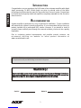 2
2
-
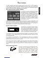 3
3
-
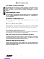 4
4
-
 5
5
-
 6
6
-
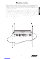 7
7
-
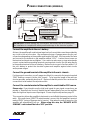 8
8
-
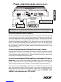 9
9
-
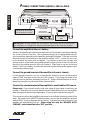 10
10
-
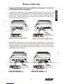 11
11
-
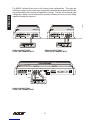 12
12
-
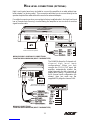 13
13
-
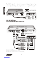 14
14
-
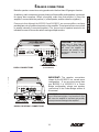 15
15
-
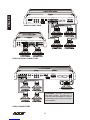 16
16
-
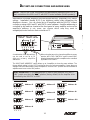 17
17
-
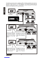 18
18
-
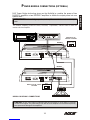 19
19
-
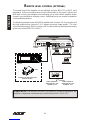 20
20
-
 21
21
-
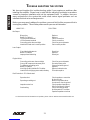 22
22
-
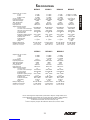 23
23
-
 24
24
-
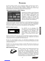 25
25
-
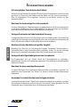 26
26
-
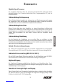 27
27
-
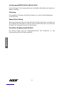 28
28
-
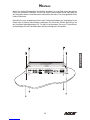 29
29
-
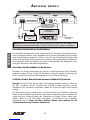 30
30
-
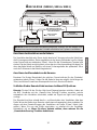 31
31
-
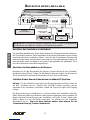 32
32
-
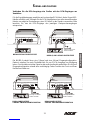 33
33
-
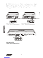 34
34
-
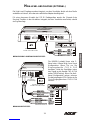 35
35
-
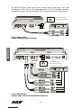 36
36
-
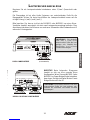 37
37
-
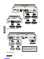 38
38
-
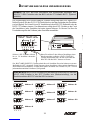 39
39
-
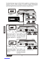 40
40
-
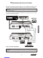 41
41
-
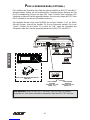 42
42
-
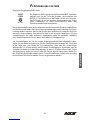 43
43
-
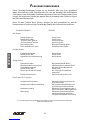 44
44
-
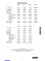 45
45
-
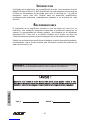 46
46
-
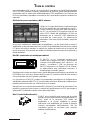 47
47
-
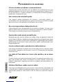 48
48
-
 49
49
-
 50
50
-
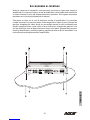 51
51
-
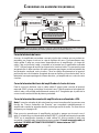 52
52
-
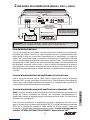 53
53
-
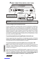 54
54
-
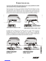 55
55
-
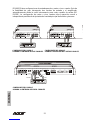 56
56
-
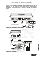 57
57
-
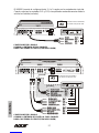 58
58
-
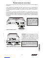 59
59
-
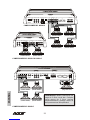 60
60
-
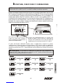 61
61
-
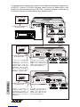 62
62
-
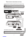 63
63
-
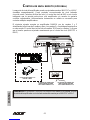 64
64
-
 65
65
-
 66
66
-
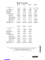 67
67
-
 68
68


NXS NX1000.1 Installation Instructions & Owner's Manual
- Categoría
- Amplificadores de audio para automóviles
- Tipo
- Installation Instructions & Owner's Manual
en otros idiomas
- English: NXS NX1000.1
- Deutsch: NXS NX1000.1
Otros documentos
-
 DS18 DSP8.8BT El manual del propietario
-
Bazooka ELA2150 Manual de usuario
-
Clarion 6610 Manual de usuario
-
Alpine MRV-F352 El manual del propietario
-
 Rockford Fosgate Prime R600-5 Guía del usuario
-
DS18 Candy-6 El manual del propietario
-
Dali AMP-2500 DSP Guía del usuario
-
Voyager POWER400 Manual de usuario
-
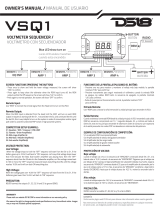 DS18 VSQ1 El manual del propietario
-
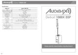 Audibax Detroit 1000X DSP El manual del propietario


