SELF FLASHING
TUBE SKYLIGHT
CLARABOYA TUBULAR DE AUTOSELLADO
GETTING STARTED
1. Read the instructions completely, making sure that you have all of the tools
needed to nish the job.
2. Determine where in the room you want the light from the Sun-Tek Tube
to shine. (Hint: For best results,always try to center the light source in the
room.) For optimum light, place on the south facing slope of the roof, if
possible, and try to avoid shaded areas.
MARKING AND CUTTING THE HOLES
◊ Note: Do not cut holes until both ceiling and roof hole locations
are marked.
Marking the Center- Ceiling
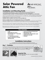
3.
Locate the center of the ceiling hole and make sure it is free of any
obstructions in the attic. One of the following methods may be helpful:
a) Have an assistant in the attic while you tap on the ceiling to indicate
where the tube will be located. Minor adjustments may need to be made
as a result of obstructions that need to be avoided, such as framing
members, A/C ducts, etc. Using a pencil, mark the
location. (See Drawing 3.4) - Or -
b) Take measurements from landmarks such as AC
registers, light xtures, etc. and transfer those
measurements to the attic. Using a small nail, tap it
through the drywall to mark the desired location.
4. Put “Easy Cut” template over or through the screw and
place a pencil in the other hole, and draw a circle on the
ceiling. Leave the screw in the ceiling. (See Drawing 3.4)
5. Using a plumb bob, nd the location on the underside
Instructions are intended for roofs with minimum 2:12 pitch and asphalt shingles.
(roof deck minimum requirement of 7/16” OSB) Instrucciones son para tejados con un
mínimo de 2:12 de brea y tejas de asfalto. (exigencia de mínimo de cubierta de azotea de
7/16” OSB)
FAILURE TO FOLLOW RECOMMENDED INSTALLATION PROCEDURES MAY VOID WARRANTY
3.4.
PARA COMENZAR
1. Lea las instrucciones completamente. y asegúrese de que tienes todas las
herramientas necesarias para completar el trabajo.
2. Determine dónde, en su cuarto, desea que la luz del Tubo de SunTek lumbre.
(Sugerencia: para mejor resultado, siempre trate de centralizar la fuente de
luz en el cuarto.) Para la mejor claridad, localize el tubo en la inclinación del
tejado que va hacia el sur y, si es posible, evite los lugares donde hay sombra.
MARCANDO Y CORTANDO LAS ABERTURAS
◊ Notar: No cortes las aberturas hasta que las localidades estén
marcadas tanto en el techo como en el tejado
Marcando el Centro - Techo
3.
Localize el centro de la abertura para el techo y asegúrese de que no haya
obstrucciones en el ático. Se sugiere uno de los siguientes métodos:
a) Tenga un asistente en el ático mientras que das palmaditas en el techo
para indicar donde el tubo será localizado. A lo mejor será necesario
hacer unos ajustes menores para evitar obstrucciones tales como vigas
estructurales, conductos del aire acondicionado, etc. Usando un lápiz,
marce el lugar. (Vea Dibujo #3.4.) - Or -
b) Coja medidas de objetos tales como registros del aire acondicionado,
instalaciones de luz, etc. y transeralas al ático. Usando un tornillo para
pared de cartón-yeso (drywall) de 3”, atornillelo atravez de la pared para
marcar el lugar deseado.
4. Pon el templet “Corte Fácil” sobre el tornillo y ponga un lápiz en el otro
agujero, y dibuje un círculo en el techo. Deje el tornillo en el techo. (Vea
Dibujo #3.4.)
5. Con el plomo, encuentre el lugar en la parte inferior del tejado que
PARTS LIST
Self Flashing Dome Assembly
Mí Asamblea de Cúpula Intermi-
tente
Roof Collar
(Flat Horizontal Retainer - 0.20 Galvanized)
Collar para cúpula
Roof Elbow (15” H)
Codo de Azotea (15” H)
Extension (22” H Straight
Connector)
Extension (22”H conector recto)
Nailing Straps (Correas para clavar)
Ceiling Elbow (15” H)
Codo de techo (15”H)
Ceiling Ring
Anillo de techo
Interior Ring & Lens
w/Screws (For 21”)
Anillo / lente interior
con tornillos
(Solo para 21”)
Interior Ring/
Lens (10” & 14”
Only)
Anillo / lente
interior
(Solo 10” & 14”)
HARDWARE INCLUDED
(2) 3” Drywall Screws
(2) 3” Tornillos para panel
de yeso
(30) 1¼” Roof
Nails
(30)1¼” Tornillos para
el tejado
(11) ⁄” TekPoint Screws
(for tube & lens)
(11) ⁄” Tornillos auto-
perforantes. (Tek-Point)
“Easy Cut” Template
(1) Plantilla “corte fácil”
#8 pph
(22) 1” Screws (10”&14”)
(29) 1” Screws (21”)
(22) 1” Tornillos (10”&14”)
(29) 1” Tornillos (21”)
(6) Caps for 21” tube
(6)Tapones 21” Solo
STS 1000 Caulk
(1) 10” or 14” tube
(2) 21” tube
STS 1000 Calafate
(1) Sellador en tubo
(10”y14”)
(2) Sellador en tubo
(21”)
Aluminum Tape
(1) Rollo de cinta
(Aluminio)
(1) Roll Insulation
(1) de Rollo Insulación
2032 - 9/09
12:12 Pitch
(3 ⁄” drop)
12:12 Baja
(de pendiente 3
⁄
”)
11:12 Pitch
(2 ⁄” drop)
11:12 Baja
(de pendiente
2 ⁄
”)
10:12 Pitch
(2 ⁄” drop)
10:12 Baja
(de pendiente
2 ⁄
”)
9:12 Pitch
(2 ⁄” drop)
9:12 Baja
(de pendiente
2 ⁄
”)
8:12 Pitch
(2 ⁄” drop)
8:12 Baja
(de pendiente
2 ⁄
”)
7:12 Pitch
(1 ⁄” drop)
7:12 Baja
(de pendiente
1 ⁄
”)
6:12 Pitch
(1 ⁄” drop)
6:12 Baja
(de pendiente
1 ⁄
”)
5:12 Pitch
(1 ⁄” drop)
5:12 Baja
(de pendiente
1 ⁄
”)
4:12 Pitch
(1 ⁄” drop)
4:12 Baja
(de pendiente
1 ⁄
”)
3:12 Pitch
(⁄” drop)
3:12 Baja
(de pendiente
⁄
”)
2:12 Pitch
(⁄” drop)
2:12 Baja
(de pendiente
⁄
”)
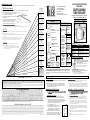
12:12 Pitch = (6” drop)
12:12 Baja = (de pendiente 6”)
2:12 Pitch = (1” drop)
2:12 Baja = (de pendiente 1”)
3:12 Pitch = (1 ½” drop)
3:12 Baja = (de pendiente 1 ½”)
4:12 Pitch = (2” drop)
4:12 Baja = (de pendiente 2”)
5:12 Pitch = (2 ½” drop)
5:12 Baja = (de pendiente 2 ½”)
6:12 Pitch = (3” drop)
6:12 Baja = (de pendiente 3”)
7:12 Pitch = (3 ½” drop)
7:12 Baja = (de pendiente 3 ½”)
8:12 Pitch = (4” drop)
8:12 Baja = (de pendiente 4”)
9:12 Pitch = (4 ½” drop)
9:12 Baja = (de pendiente 4 ½”)
10:12 Pitch = (5” drop)
10:12 Baja = (de pendiente 5”)
11:12 Pitch = (5 ½” drop)
11:12 Baja= (de pendiente 5 ½”)
1:12 Pitch = (½” drop)
1:12 Baja = (de pendiente ½”)
Flat Roof = (0” drop)
Tejado plano = (pendiente 0”)
Use for
Cathedral Type
Ceilings
Use para techos tipo
catedral
Use for Flat Ceilings
Use para tejados planos
SLOPE CHART Gráca de inclinación
DETERMINING ROOF PITCH
Your “ROOF PITCH” is simply how far the roof drops vertically for every 12” of horizontal run. There are two dierent ways to determine
your roof slope.
Method One: (The Level Method)
1.
Take a carpenter’s level and place it against your roof as shown in the illustration below. Be sure it is level.
2. From the point where the level touches the roof, measure out 12 inches.
a) From this point, measure the distance in inches from
the bottom of the level to the roof.
3. This will be the rst number in the roof pitch. The second
number is always 12.
4. Use the slope chart (See Amount of Drop) to determine
the amount you will need to drop the mark for the roof
hole down the slope of your roof as indicated.
Sun-Tek Manufacturing, Inc.
10303 General Drive
Orlando, Florida 32824
(407) 859-2117
www.Sun-Tek.com
CustomerService@Sun-Tek.com
SUN-TEK TUBE LIMITED WARRANTY
Sun-Tek Industries, Inc. (“Sun-Tek”), 10303 General Drive, Orlando, Florida 32824, (407) 859-2117, warrants this tubular skylight on the following terms and conditions: A. Warranty Coverage:
This warranty applies to both the original purchaser and rst consumer-owner. B. Warranty Duration: This warranty shall remain in eect for a period of ten (10) years after the date the tube is
purchased or the date it is delivered to the rst consumer-owner, whichever is later. C. Warranty Application: This warranty applied only to the materials and fabrication of the tube and does
not apply to any defect or damage caused by improper use, improper installation, improper care, shipping damage or accident. This warranty does not cover any cosmetic changes in the tube,
including, but not limited to, pitting, hazing, pant nish, discoloration. D. Performance by Sun-Tek: During the warranty period, Sun-Tek will provide free of charge an equivalent new tube (or
component thereof) for one found to be defective in material or workmanship. Shipping costs of such replacements are not the responsibility of Sun-Tek. Sun-Tek will not be responsible for any
costs of removal or re-installation. E. Validation Procedure: To obtain performance under this warranty, the purchaser must: (1) On installed tubes, contact Sun-Tek for instructions before
removing tube. Removal of tube from roof before inspection will void warranty. (2) Notify Sun-Tek in writing of any claim within (30) days after the defect is discovered. (3) Sun-Tek or its
authorized agents must examine
high quality installed photographs of
the tube and determine to its satisfaction whether the defect is covered by this warranty; and (4) present a copy of the receipt
as roof of purchase. F. Implied Warranties: IMPLIED WARRANIES, INCLUDING BUT NOT LIMITED TO, IMPLIED WARRANTIES OF MERCHANTABILITY AND FITNESS FOR A PARTCULAR PURPOSE, SHALL
NOT EXTEND BEYOND THE DURATION OF THE EXPRESS WARRANTIES PROVIDED HEREON. Some states do not allow limitations of how long an implied warranty lasts, so the above limitation may
not apply to you. G. Incidental or Consequential Damages: SUN-TEK SHALL NOT BE LIABLE FOR ANY INCIDENTAL OR CONSEQUENTIAL DAMAGES WHATSOEVER, INCLUDING, BUT NOT LIMITED
TO, LOSS OF TIME OR REVENUE, DAMAGE RESULTING TO OTHER PROPERTY OR EXPENSES, except where states may not allow it. H. Exclusive Warranty: THIS WARRANTY IS EXCLUSIVE AND IN LIEU
OF ALL OTHER WARRANTIES. This warranty gives you specic legal rights. You may have other rights which vary from state to state.
GARANTIA LIMITADA DEL TUBO DE SUNTEK
Sun-Tek Manufacturing, Inc. (“Sun-Tek”), 10303 General Drive, Orlando, Florida 32824, (407) 859-2117, garantiza esta claraboya tubular bajo los siguientes términos y condiciones: A: Alcance de la Garantía: Esta garantía: se aplica
tanto al comprador original y al primer dueño-consumidor. B: Duración de la Garantía: Esta garantia será efectiva por un periodo de diez (10) años después de la fecha de compre del tubo o la fecha que es entragada al primer dueño-
consumidor, cual sea mas reciente. C. Aplicación de la Garantía: Esta garantía es aplicada solo a los materiales y la fabricación del tubo y no se aplica a cualquier defecto o daño causado por el uso impropio, instalación impropia,
cuido impropio, daño de envio o accidentes. Esta garantía no cubre cambios cosméticos en el tubo, incluyendo, pero no limitado, a hoyos, neblina, apariencia de pintura, descolorización. D. Función de Sun-Tek: Durante el periodo
de la garantía, Sun-Tek proveerá sin costo un tubo nuevo equivalente (o un componente del mismo) por uno que se encuentre defectivo en material o en hechura. Costo de envio de estos repuestos no son responsabilidad de Sun-
Tek. Sun-Tek no será responsable por el costo de la eliminación o reinstalación. E. Procedimiento de Validez: Para obtener ejecución bajo esta garantía, el comprador tiene que: (1) Ponerse en contacto con Sun-Tek si el tubo ya esta
instalado para recibir instrucciones antes de removerlo. Remover el tubo del tejado antes de inspección anula la garantía. (2) Noticar a Sun-Tek atraves de correspondencia de alguna reclamación dentro de (30) días si un defecto
es descubierto. (3) Sun-Tek o algunos de sus agentes autorizados tiene que examinar el tubo y determinar a su satisfacción si el defecto está cubrido por la garantía; y (4) presentar una copia del recibo como prueba de compre. F.
Garantías Implicitas: GARANTIAS IMPLICITAS, INCLUYENDO, PERO NO LIMITADAS A, GARANTIAS IMPLICITAS DE COMERCIABILIDAD O APTITUD IMPLICITAS PARA UN PROPOSITO DETERMINADO QUE PROVENGAN DEL MINISTERIO
DE LEY ESTAN POR LA PRESENTE EXPRESAMENTE LIMITADAS A LA GARANTIA LIMITADA ESTABLECIDA MAS ARRIBA. Algunos estados no permiten limitaciones sobre la duración de una garantía implicita, por lo tanto la limitaciones
anteriores pueden no aplicarse a usted. G. Daños Indirectos o Incidentales: SUN-TEK NO SERA RESPONSABLE POR NINGUNOS DANOS INDIRECTOS O INCIDENTALES, INCLUYENDO, PERO NO LIMITADO A, PERDIDA DE TIEMPO O
INGRESOS, DANO RESULTANDO DE OTRA PROPIEDAD O GASTOS, excepto donde un estado no lo permite. H. Garantía Exclusiva: ESTA GARANTIA ES EXCLUSIVA Y QUEDA EN PIE SOBRE CUALQUIER OTRA GARANTIA. Esta garantía
limitada le otorga derechos legales especicos. Tambien puede tener otros derechos que varian según el estado en el cual resida.
All installation information is supplied in good faith, but without recommendation as to its use. No guarantee of the results of any use of this information
is to be implied, since conditions of use are beyond our control. Please consult local building codes for compliance before installing. When assembling
tube, do not place tools or other items on the dome as it may scratch.
Toda la información de instalación suministrada se hace de buena fé, pero sin recomendaciones en cuanto a su uso. Ninguna garantía del uso de esta información deberá
ser implicada, ya que las condiciones de su uso están fuera de nuestro control. Por favor consulte los códigos locales y su acatamiento antes de instalarlo. Cuando arme el
tubo, no ponga herramientas u otros objetos en la cúpula que la puedan raspar.
INSTALLATION INSTRUCTIONS
TUBE SERIES
You will need: Herramientas Necesarias
• Pencil (el Lápiz) • Utility Knife (Cuchilla de Navaja)
• Ladder (Escalera) • Plumb Bob (Plomo)
• Jig Saw (Sierra Jig) • Tin Snips (Tijeras de estaño)
• Square (esquina) • Pry Bar (Palanca de Barra)
• Tape Measure
(Cinta de Medir)
• Screwdriver (Phillips)
Destornillador (Filips)
• Caulking Gun
(Pistola Para
Calafatear)
• Safety Equipment (glasses, gloves, etc.)
Equipo de Seguridad (anteojos, lentes,
guantes,etc.)
Metodo Uno:
1.
Usando un nivel de carpintero póngalo en el tejado como se muestra en la ilustración de abajo. Asegurese que esta
a nivel.
2. Desde el punto en que el nivel toca el tejado, mida 12”.
a) Desde este punto, mida la distancia en pulgadas desde la parte de abajo del nivel hasta
el tejado.
3. Este será el primer número de la inclinación del tejado. El segundo numero siempre es 12.
4. Use la gráca de abajo (Vea inclinación) para determinar la medida que necesitará para dejar
caer hacia abajo de la inclinación la marca del agujero del tejado como se indica.
Method Two: (The Slope Chart Method)
1.
Use our roof slope chart and visually determine the pitch of your roof.
a) Corresponding to that pitch is a drop length. Drop the mark for the roof hole directly down the slope
as indicated.
Metodo Dos
1.
Use nuestra gráca de inclinación (Vea Gráca De Inclinación) y
visualmente determine la inclinación de su tejado.
a) Correspondiente a esa inclinación es la medida de la caída. Deje
caer la marca para el agujero del tejado directamente debajo de
la inclinación como se indica.
OPTIONS FOR YOUR TUBE SKYLIGHT:
LIGHT KIT (Estuche de Luz)
You can use your Sun-Tek Tube as an extra
light source DAY OR NIGHT with the addition
of our special light kit.
Usted puede usar su Tubo de Sun-Tek como
una fuente de luz adicional DIA Y NOCHE con la
adición de un estuche de luz especial.
EXTENSION TUNNELS (Tuneles de Extensión)
Extension tunnels are available for situations requiring
more than 50 inches of tubing.
Tuneles de extensión son disponibles para situaciones
requiriendo más de 50 pulgadas de tubo.
Sizes 10” 14” 21” Medidas
INSTRUCCIONES PARA INSTALACION

of the roof that lies directly above the drywall screw, that
indicates the center of the ceiling hole. Mark that location
with a pencil mark. Using page titled “ DETERMINING ROOF
PITCH”, determine which slope best represents the roof
where your tube is to be installed. Drop the mark for the roof
hole directly down the slope by the amount indicated for
the slope of your roof. For example (See Drawing 5A), if your
roof is a 3:12 pitch, you would move the mark for the center
of roof hole 1 ½” down the slope of the roof for a at ceiling
and 15/16” for a cathedral ceiling. Mark the location with a 3”
drywall screw by screwing up through the roof deck.
◊ If the above method does not work for your application, take
both elbows into the attic and place where you want the
openings to be. Adjust and move the elbows until they align
with each other and trace the outside and nd the center. This
is the center location for your roof and ceiling holes.
Cutting the Hole in the Ceiling
6.
Cut hole opening in the drywall using a key hole or jig saw.
Use the screw to hold the cut out section.
Marking the Center- Roof
7.
Place the “Easy cut” template over the screw that protrudes
up through the roof and scratch out a circle using a nail or
screw. (See Drawing 7,8)
Cutting the Hole in the Roof
8.
Using a key hole or jig saw, cut the hole in the roof.
Removing the Shingles
9.
Using a pry bar, carefully remove enough shingles to allow
the ange of the tube to lie at on the felt paper. The ange
of the dome should sit on top of the shingle at the bottom
of the opening, therefore, do not remove it. Carefully pull
the nails or fasteners out of all the shingles that are being
removed, being sure NOT TO DAMAGE THE SHINGLES AS
THEY WILL BE USED AGAIN. Leave plastic covering on dome
until roof installation is complete.
queda directamente sobre el tornillo que indica el centro de la abertura
para el techo. Marce el lugar con un lápiz. Usando la página titulada
“DETERMINANDO LA INCLINACIÓN DEL TEJADO”, determine cual inclinación
mejor representa el tejado donde su tubo será instalado. Cuelge la marca
para la abertura de su tejado directamente para abajo de la inclinación de
acuerdo a la cantidad indicada para la inclinación de su tejado. Por ejemplo
(Vea Dibujo 5.A.), si su tejado es de 3:12 de brea, usted pondría el marco para
el centro de la abertura del tejado 1 ½” abajo de la inclinación del techo para
un techo plano y 15/16” para un techo catedral. Marque la ubicación con
un tornillo de 3” para panel de yeso atornillándolo a través del entarimado
del tejado. Si el método anterior no trabaja para su aplicación, lleve los dos
codos al ático, y colóquelos donde usted quiere que vaya la abertura. Ajuste
y mueva los codos hasta que ellos alineen uno con el otro, trace el exterior y
encuentre el centro. Esta es la ubicación central para sus agujeros del tejado
y del techo para un techo plano y 15/16” para un techo catedral. Marque la
ubicación con un tornillo de 3” para panel de yeso atornillándolo a través del
entarimado del tejado.
◊ Si el método anterior no trabaja para su aplicación, lleve los dos codos al ático,
y colóquelos donde usted quiere que vaya la abertura. Ajuste y mueva los codos
hasta que ellos alineen uno con el otro, trace el exterior y encuentre el centro. Esta
es la ubicación central para sus agujeros del tejado y el techo.
Cortando la Abertura en el Techo
6.
Haga la abertura en el techo usando un la sierra jig. Use el tornillo para
aguantar la sección que has cortado.
Marcando el Centro - Tejado
7.
Ponga el templet “Corte Fácil” sobre el tornillo que sobresale a través del
tejado y raspe un círculo usando un clavo o un tornillo. (Vea Dibujo #7.8.)
Cortando la Abertura en el Tejado
8.
Usando la sierra jig, haga la abertura en el tejado.
Removiendo los Tejas
9.
Usando un barra de hierro, cuidadósamente remueve sucientes tejas para
permitir que el borde del tubo quede plano sobre el papel de elto. El borde
de la cúpula debe quedar sentada sobre la teja a la parte de abajo de la
abertura, por lo tanto, no lo remueva. Cuidadósamente quite los clavos o los
broches de las tejas que se estan removiendo, asegúrandose de que NO LE
HAGAS DAÑO A LAS TEJAS YA QUE SE USARÁN DE NUEVO. Deje la cobertura
de plástico sobre la cúpula hasta que la instalación del tejado se complete.
5a.
7. 8.
17a.
18. 19.
20.
21.
INSTRUCCIONES PARA INSTALACIÓN DE ÁTICOS
SUPERFICIALES, LEA LO SIGUIENTE, 1 S.A. 10 S.A.
Marcar y hacer los agujeros.
1.sa
Antes taladrar o cortar cualquier agujero, cerciórese que la ubicación
está libre de obstrucciones. Coloque un tornillo o clavo a través de un
lado de la plantilla y conéctela al techo. Marque el techo con un lápiz
rotando la plantilla (vea dibujos 3,4). Remover la plantilla. Usar un taladro
con extensión y barrena (mínimo 1/4”), taladrar perpendicular al techo y
a través del tejado.
2.sa Corte el agujero en el techo.
3.sa Usar la plantilla centrada en el agujero del tejado, marca el tejado y corte
el agujero.
4.sa Remover la película protectora de adentro del codo del techo y de la
extensión, si la extensión es necesaria.
Si la extensión es necesaria.
5.sa
Envuelva la extensión alrededor de los codos del techo; súper
impóngase 1 a 2 pulgadas. Quite la parte de atrás de la cinta adhesiva y
presione para juntar la extensión. Conecte la extensión al codo del techo
usando tres tornillos de punta debarrena como se muestra (vea las X en
el dibujo 5.S.A.). Selle todas las orillas y uniones con cinta adhesiva de
conducto.
6.sa Coloque las correas para clavar alrededor del exterior del tubo y
manténgalo en posición con cinta adhesiva. . Si se necesita correa
adicional, asegúrelas rmemente con tornillos. (Correa adicional no se
proporciona.)
7.sa Empuje el tubo hacia arriba del techo hasta que el anillo de metal en el
fondo del codo del techo esté parejo y holgado con el techo. Marque el
tubo desde el tejado parejo con el entarimado del tejado. (Vea la línea
punteada en dibujo 7.S.A.). Hale el tubo hacia afuera de la abertura. Hale
las correas fuera del tubo y corte el tubo 1” encima de la marca.
8.sa Doble las correas alrededor de los lados y hacia adentro del tubo.
Empuje el tubo hacia arriba por la abertura del techo hasta que el anillo
de metal del codo del techo esté holgado y parejo con el techo.
9.sa Clave las correas al entarimado del tejado a 2” de la apertura y corte el
exceso de la correa. Haga cortes cada 1” alrededor del tubo hacia abajo
del entarimado del tejado para formar las lengüetas. Doble las lengüetas
sobre y parejas con el entarimado del tejado (Ve dibujo 9.S.A.). Selle
la cima del tubo para prevenir el intercambio de aire entre el ático y el
tubo. La cinta de masilla trabaja bien. (Cinta de masilla no incluida).
10.sa El tejado debe ser terminado hasta donde está la abertura antes de que
la cúpula sea instalada. (Seguir las instrucciones 12-21)
FOR SHALLOW ATTIC INSTALLATION INSTRUCTIONS
READ THE FOLLOWING 1 S.A10 S.A.
Marking and Cutting the Holes
1.sa
Before drilling or cutting any holes, make sure the intended location
is free of obstructions. Place a screw or nail through one side of the
template and attach to the ceiling. Mark the ceiling with a pencil by
rotating the template (See Drawing 3.4.). Remove
the template. Using a drill bit (1/4” minimum) with
extension, drill perpendicular to the ceiling and up
through the roof.
2.sa Cut the hole in the ceiling.
3.sa Using the template, centered at the hole in the roof,
mark the roof and cut the hole.
4.sa Remove the protective lm from inside the ceiling
elbow and the extension, if extension is necessary.
IF EXTENSION IS NEEDED
5.sa
Wrap the extension around the ceiling elbow, overlap
1 to 2 inches. Remove the backing to the tape on the
extension and press the extension together. Attach the
extension to the ceiling elbow using three Tek-Point
screws as shown (See the X’s on Drawing 5.S.A.). Seal all
seams and joist with duct tape.
6.sa Place the nailing straps along the outside of the tube
and hold in place with tape. If additional strapping is
needed, attach securely with screws. (Additional strap
not provided)
7.sa Push the tube up through the ceiling until the metal
ring on the bottom of the ceiling elbow is ush and
snug with the ceiling. Mark the tube from the roof ush
with the roof deck (See dotted line on Drawing 7. S.A.).
Pull the tube back out of the opening. Pull straps out of
tube and cut the tube 1” above the mark.
8.sa Fold the straps along the sides and into the tube. Push
the tube up through the ceiling hole until the ceiling
elbow metal ring is ush and snug with the ceiling.
9.sa Nail the straps to the roof deck 2” from the opening and
cut o the excess strap. Make cuts every 1” around the
tube down to the roof deck to form tabs. Bend the tabs
over ush with the roof deck (See Drawing 9.S.A.). Seal
the top of the tube to prevent air exchange between
the attic and the tube. Putty tape works well. (Putty tape
not included)
10.sa The roof should be shingled up to the bottom of the
roof opening before the dome is installed. (Follow Instructions 12-21)
5.
9.
5sa.
7sa.
9sa.
10.
10a.
12.
17.
13.
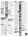
ASSEMBLY OF TUBE
10. Insert the roof elbow through the hole in the roof so that
the ange of the elbow is resting at on the roong felt. To
help minimize adjustments during the assembly process,
place the seam in the elbow in the 12 o’clock position
(top of the opening). Slide the elbow to the bottom of the
opening and place the roof collar under the ange from
the top of the opening (See Drawing 10A). Place the two
roong nails in the roof collar to hold it in position. Remove
plastic protection sheet from inside the roof elbow.
11. The shingles that have a curved cut in them should have
the curve trimmed ¼” larger to allow for the thickness of
the dome material. (NOTE: Dry t the shingles into position
to keep sealant from getting on the dome.)
12. Place a ⁄” diameter bead of STS 1000 sealant (included)
around the opening on the roof set back from the edge 1
¼”. Place a second ⁄” bead set back 1 ¼” from the rst bead.
(See Drawing 12)
13. Remove protective lm from bottom of dome. Place the
dome over the opening with the “This Edge Down” sticker
to the bottom of the opening. Center over the opening,
and press into place (See Drawing 13). IMPORTANT: Bottom
ange of skylight MUST go on top of shingles.
14. Fasten the dome to the roof using the #8 pph x 1” screws
provided. Fastener spacing not to exceed 2 ½”. Do not nail
or screw through ange except where holes
are provided. DO NOT OVER TIGHTEN.
15. Run a bead of STS 1000 sealant around the
perimeter of the ange where it touches the roof. Also, seal
the head of every installation screw.
◊ NOTE: USE OF ANY SEALANT OTHER THAN STS 1000, VOIDS
WARRANTY. Take plastic covering o dome.
16. Replace the shingles from the bottom up. Roong nails are
provided. CAUTION: DO NOT PUT A NAIL THROUGH THE
FLANGE OF THE DOME. The bottom ange of the dome
can be covered with a shingle but DO NOT seal this shingle
down to the top of the ange.
17. Push the interior elbow up through the ceiling hole (See
Drawing 17). From inside the attic, pull the elbow up so that
the ange is ush with the ceiling. Align ceiling elbow seam
with the seam in the roof elbow. Pull a nailing strap snugly
to a rafter and nail into place with 1 ¼” roong nails. Repeat
with the second nailing strap. If a nailing position cannot be
reached with the nailing strap, an additional 2 x 4 may need
to be added between the joists. Remove plastic protection
sheet from inside the ceiling elbow (See Drawing 17A).
18. Rotate both the ceiling and roof elbows so that they align
with each other. The elbows rotate best when handled
gently. REMINDER: ALL PLASTIC PROTECTION IN ELBOWS
AND EXTENSIONS SHOULD BE REMOVED BY THIS TIME.
Fit the straight connector on the outside of the elbows to
conrm t. While holding the straight connector in position,
remove the backing on the double sided tape and press
rmly to adhere the tube to itself.
19. Attach the extension to the elbows using the Tek-Point
screws provided. Equally space 3 screws through the
overlap at the extension and the elbows and 2 screws
through the overlapped seams of the extension. (See the X’s
on Drawing 18 & 19)
a) Use the duct tape to seal all joints and seams in the tube
assembly. Sun-Tek recommends for maximum thermal
performance wrapping the tube with insulation to
reduce heat loss and condensation.
Interior Lens (For 10” & 14” ONLY)
20.
Lubricate the gasket on the lens using petroleum jelly or
liquid soap. Push the gasket side of the ring/lens assembly
into the ceiling elbow until the magnets make contact with
the steel ring. (See Drawing 20)
Interior Dome (For 21” ONLY)
21.
Place the interior dome gasket around the edge of the
interior dome.
22. Align the interior dome with the tabs on the interior tube
and fasten screws as shown in Drawing 21. DO NOT OVER
TIGHTEN. Snap the screw covers closed. The job is complete.
Cleaning: Use a mild glass cleaner and a clean
sponge or soft cloth.
MONTAJE DEL TUBO
10. Insertar el codo para el tejado atravez de la abertura en el tejado hasta que
el borde del codo quede plano sobre el papel de elto. Para ayudar a evitar
muchos ajustes durante el proceso de montaje, ponga la juntura del codo
en la posición de las 12 en un reloj (parte arriba de la abertura). Si hay una
brecha visible entremedio del codo y la abertura, deslize el codo para la
parte de abajo de la abertura y ponga el cuello para el tejado debajo del
borde desde la parte de arriba de la abertura. (Vea Dibujo 10.A.) Clave el
cuello en posición para sujetarlo. Remueva el plástico de protección de
adentro del codo para el tejado.
11. Las tejas que tengan un corte curvado deben tener el curvado recortado ¼”
más para dejar espacio para la densidad del material de la cúpula. (NOTAR:
Acomode los tejas en su posición sin el uso de sellante para evitar que el
sellante caiga sobre la cúpula.)
12. Ponga unos glóbulos del sellante STS1000 de un ⁄” diámetro (incluido)
alrededor de la abertura en el tejado como un 1 ¼” de distancia del la orilla.
Ponga otros glóbulos de sellante de un 3/8” de distancia 1 ¼” de distancia del
primer glóbulo. (Vea Dibujo 12.)
13. Quitar la película protectora del fondo de la cúpula. Ponga la cúpula sobre
la abertura con el lado que tiene la etiqueta que lee “Este Lado Hacia Abajo”
hacia la parte de abajo de la abertura. Centralize sobre la abertura, y oprima
en posición. (Vea Dibujo 13.) IMPORTANTE: La parte de abajo del borde TIENE
que quedar encima de las tejas.
14. Sujete la cúpula al tejado usando los #8 pph x 1” tornillos proveidos. No
sobre apretes. Espaciado de sujetador para no exceder 2 ½”. Se debe usar
un tornillo en cada roto de instalación proveido. No clavar ni atornillar el
reborde excepto donde está agujereado. No sobre apriete.
15. Corra unos glóbulos del sellante STS1000 alrededor del perímetro del borde
donde toca el tejado. También, selle la cabeza de cada tornillo de instalación.
◊ NOTAR: USO DE CUALQUIER OTRO SELLANTE QUE NO SEA EL STS1000, ANULA LA
GARANTÍA. Quitar cobertura de plástico de la cúpula.
16. Vuelva a colocar las tejas desde abajo hacia arriba. Clavos son proveidos.
AVISO: NO PONGAS UN CLAVO A TRAVÉS DEL BORDE DE LA CÚPULA. El
borde de abajo de la cúpula puede ser tapado con una teja pero NO lo selles
al borde.
17. Empuje el codo interior atravez de la abertura en el techo (Vea Dibujo 17.).
De adentro del ático, jale el codo hacia arriba para que el borde quede
plano con el techo. Alínie la junta del codo del techo con la junta del codo
del tejado. Jale una correa de clavar para que quede apretada a una viga
y clavela en posición usando clavos de 1 ¼”. Repite con la segunda correa.
Si una posición para clavar no se puede alcanzar con las correas, una viga
adicional de 2 x 4 se tendrá que añadir entremedio de la Vigueta (Viga). Quite
la hoja de protección plástica de dentro del codo para el techo (Vea Dibujo
17.A.).
18. Hacer girar los codos hasta que queden alineados uno con el otro. Los
codos dan vuelta con mejor resultado cuando se manejan suavemente.
RECORDATORIO: TODA PROTECCIÓN PLÁSTICA EN CODOS Y EXTENSIONES
DEBE HABER SIDO REMOVIDA EN ESTA ETAPA. Ponga la extensión (conector
recto) encima de los codos para conrmar el encaje. Mientras aguantes el
conector recto en posición, quite el endose en la tela adhesiva de doble-lado
y oprima rmemente para que quede el tubo pegado a si mismo.
19. Atar la extensión a los codos usando los tornillos de punta Tek distribuidos
en espacio equitatívamente 3 tornillos a través, por encima de la extensión y
los codos y 2 tornillos através, por encima de la junta de la extensión. (Vea las
X’s en el dibujo #18.19.).
a) Use la cinta de tela adhesiva (Duct Tape) para sellar todas las coyunturas y
junturas enel montaje del tubo. Sun-Tek recomienda para funcionamiento
máximo thermal el envolver el tubo con insulación para reducir la pérdida
de calefacción y condensación.
Cúpula Interior (For 10” & 14”)
20.
Lubricar la junta (empaque) del lente con jalea de petróleo o jabón líquido.
Empuje el lado de la junta (empaque) del ensamblaje del anillo / lente en el
codo del techo hasta que los imanes hagan contacto con el anillo de acero.
(Vea dibujo 20)
Cúpula interior (solamente para 21”)
21.
Coloque la junta de cúpula interior alrededor del borde de la cúpula interior.
22. Alinee la cúpula interior con las etiquetas en el tubo interior y sujete tornillos
como mostrado en el Dibujo 21. No VUELVA A HACER SE APRIETAN. Rompa
las tapas de tornillo cerradas. El trabajo es completo.
Limpieza: Use un limpiador de espejo suave y una esponja
limpia o un trapo suave.
Sun-Tek Manufacturing, Inc. • 10303 General Drive • Orlando, Fl. 32824 • (407) 859-2117 • www.Sun-Tek.com • CustomerService@Sun-Tek.com
-
 1
1
-
 2
2


Sun-Tek STT.10 Guía de instalación
- Tipo
- Guía de instalación
- Este manual también es adecuado para
en otros idiomas
- English: Sun-Tek STT.10 Installation guide