Craftsman 28947 - GT 5000 26 HP/54" Garden Tractor Manual de usuario
- Categoría
- Cortadoras de césped
- Tipo
- Manual de usuario

Operator's Manual
®
GAR E
26.0 HP,* 54"
Electric Start
TRACTO
Mower
Automatic Transmission
Model No.
917.28947
• Espadol, p. 36
This product has a low emission engine which operates
differently from previously built engines. Before you start the
engine, read and understand this Owner's Manual.
IMPORTANT:
Read and follow all Safety
Rules and Instructions before
operating this equipment.
For answers to your questions
about this product, Call:
1=800-659-5917
Sears Craftsman Help Line
5 am - 5 pm, Mon - Sat
SEARS, ROEBUCK AND CO., HOFFMAN ESTATES, IL 60179 U.SoA.
Visit our Craftsman website:www, sears.com/craftsman *As rated by the engine manufacturer
425987 Rev. 4

Warranty .................................................. 2
Safety Rules ............................................ 3
Product Specifications ............................. 6
Assembty/Pre-Operation ......................... 8
Operation ............................................... 13
Maintenance Schedule .......................... 21
Maintenance .......................................... 21
Service and Adjustments ....................... 26
Storage .................................................. 31
Troubleshooting ..................................... 32
Sears Service ......................... Back Cover
Craftsman Riding Equipment Warranty:
Lawn Tractors, Garden Tractors, Zero Turn Riders
CRAFTSMAN TWO YEAR FULL WARRANTY
FOR TWO YEARS from the date of purchase, if any non-expendable part of this riding
equipment fails due to a defect in material or workmanship, visit wv.ev.craftsman.com or
call 1-800-659_-5917 to arrange for free in-home repair.
The frame and front axle will be repaired free of charge for five years from the date of
purchase if defective in material or workmanship.
in al! cases, if repair proves impossible, the riding equipment will be replaced free of
charge with the same or an equivalent model.
The battery will be replaced free of charge for 90 days from the date of purchase if
defective in material or workmanship (our testing proves that it will not hold a charge)°
This warranty is void if this product is ever used while providing commercial services or if
rented to another person.
This warranty covers ONLY defects in material and workmanship. Warranty
coverage does NOT include:
o Expendable items that can wear out from normal use within the warranty period,
including but not limited to blades, spark plugs, air cleaners, belts, and oil filters.
° Standard maintenance servicing, oil changes, or tune-ups.
o Tire replacement or repair caused by punctures from outside objects, such as nails,
thorns, stumps, or glass.
= Tire or wheel replacement or repair resulting from normal wear, accident, or improper
operation or maintenance.
= Repairs necessary because of operator abuse, including but not limited to damage
caused by towing objects beyond the capability of the riding equipment, impacting
objects that bend the frame or crankshaft, or over-speeding the engine.
= Repairs necessary because of operator negligence, including but not limited to,
electrical and mechanical damage caused by improper storage, failure to use the
proper grade and amount of engine oil, failure to keep the deck clear of flammable
debris, or failure to maintain the riding equipment according to the instructions
contained in the operator's manual.
• Engine (fuel system) cleaning or repairs caused by fuel determined to be
contaminated or oxidized (stale). In general, fuel should be used within 30 days of its
purchase date.
• Normal deterioration and wear of the exterior finishes, or product label replacement.
This warranty gives you specific legal rights, and you may also have other rights which
vary from state to state.
Sears Brands Management Corporation, Hoffman Estates, IL 60179
2

_DANGER: This cutting machine is capable of amputating hands and feet and
throwing objects. Failure to observe the following safety instructions could result
in serious injury or death.
_WARNING: In order to prevent acciden-
tal starting when setting up, transporting,
adjusting or making repairs, always discon-
nect spark plug wire and place wire where
it cannot contact spark plug.
_WARNING: Do not coast down a hill in
neutral, you may lose control of the tractor.
_WARNING: Tow only the attachments
that are recommended by and comply with
specifications of the manufacturer of your
tractor. Use common sense when towing.
Operate only at the lowest possible speed
when on a slope. Too heavy of a load, while
on a slope, is dangerous. Tires can lose
traction with the ground and cause you to
lose control of your tractor.
_WARNING: Engine exhaust, some of
its constituents, and certain vehicle compo-
nents contain or emit chemicals known to the
State of California to cause cancer and birth
defects or other reproductive harm.
_WARNING: Battery posts, terminals and
related accessories contain lead and lead
compounds, chemicals known to the State of
California to cause cancer and birth defects
or other reproductive harm. Wash hands
after handling,
i. GENERAL OPERATION
• Read, understand, and follow all instruc-
tions on the machine and in the manual
before starting.
° Do not put hands or feet near rotating
parts or under the machine. Keep clear
of the discharge opening at all times.
° Only allow responsible adults, who are
familiar with the instructions, to operate
the machine.
• Clear the area of objects such as rocks,
toys, wire, etc., which could be picked
up and thrown by the blades.
• Be sure the area is clear of bystanders
before operating. Stop machine ifanyone
enters the area.
° Never carry passengers.
• Do not mow in reverse unless absolutely
necessary. Always took down and behind
before and while backing.
o
o
o
o
6
o
Never direct discharged material toward
anyone, Avoid discharging material
against a wall or obstruction. Material
may ricochet back toward the operator.
Stop the blades when crossing gravel
surfaces.
Do not operate machine without the en-
tire grass catcher, discharge chute, or
other safety devices in place and working.
Slow down before turning.
Never leave a running machine unat-
tended. Always turn off blades, set
parking brake, stop engine, and remove
keys before dismounting.
Disengage blades when not mowing.
Shut off engine and wait for all parts to
come to a complete stop before cleaning
the machine, removing the grass catcher,
or unclogging the discharge chute.
Operate machine only in daylight or good
artificial light.
Do not operate the machine while under
the influence of alcohol or drugs.
Watch for traffic when operating near or
crossing roadways.
Use extra care when loading or unloading
the machine into a trailer or truck.
Always wear eye protection when operat-
ing machine.
Data indicates that operators, age 60
years and above, are involved in a large
percentage of riding mower-related inju-
ries. These operators should evaluate
their ability to operate the riding mower
safely enough to protect themselves and
others from serious injury.
Follow the manufacturer's recommen-
dation for wheel weights or counter-
weights.
Keep machine free of grass, leaves or
other debris build-up which can touch hot
exhaust / engine parts and burn. Do not
allow the mower to plow leaves or other
debris which can cause build-up to oc-
cur. Clean any oil or fuel spillage before
operating or storing the machine. Allow
machine to cool before storage.
3

II. SLOPE OPERATION
Slopes are a major factor related to loss of
control and tip-over accidents, which can
result in severe injury or death. Operation
on all slopes requires extra caution. If you
cannot back up the slope or if you feel uneasy
on it, do not mow it.
- Mow up and down slopes, not across.
- Watch for holes, ruts, bumps, rocks, or
other hidden objects. Uneven terrain
could overturn the machine. Tall grass
can hide obstacles.
• Choose a tow ground speed so that you
will not have to stop or shift while on the
slope,
• Do not mow on wet grass. Tires may lose
traction,
Always keep the machine in gear when
going down slopes. Do not shift to neutral
and coast downhill,
• Avoid starting, stopping, or turning on a
slope, Ifthetireslosetraction, disengage
the blades and proceed slowly straight
down the slope,
, Keep all movement on the slopes slow
and gradual. Do not make sudden
changes in speed or direction, which
could cause the machine to roll over.
° Use extra care while operating machine
with grass catchers or other attachments;
they can affect the stability of the ma-
chine. Do no use on steep slopes.
• Do not try to stabilize the machine by
putting your foot on the ground.
• Do not mow near drop-offs, ditches,
or embankments. The machine could
suddenly roll over if a wheel is over the
edge or if the edge caves inn
ill. CHILDREN
Tragic accidents can occur if the operator
is not alert to the presence of children.
Children are often attracted to the machine
and the mowing activity. Never assume
that children will remain where you last
saw them.
• Keep children out of the mowing area
and in the watchful care of a responsible
adult other than the operator.
• Be alert and turn machine off if a child
enters the area.
, Before and while backing, look behind
and down for small children°
4
• Never carry children, even with the
blades shut off. They may fat! off and
be seriously injured or interfere with safe
machine operation. Children who have
been given rides in the past may suddenly
appear in the mowing area for another
ride and be run over or backed over by
the machine.
• Never allow children to operate the ma-
chine°
• Use extra care when approaching blind
corners, shrubs, trees, or other objects
that may block your view of a child°
IV, TOWING
, Tow only with a machine that has a hitch
designed for towing. Do not attach towed
equipment except at the hitch point.
• Followthe manufacturer's recommenda-
tion for weight limits for towed equipment
and towing on slopes.
° Never allow children or others in or on
towed equipment.
° On slopes, theweightofthe towed equip-
ment may cause loss of traction and loss
of control.
° Travel slowly and allow extra distance to
stop.
V. SERVICE
SAFE HANDLING OF GASOLINE
To avoid personal injury or property dam-
age, use extreme care in handling gasoline_
Gasoline is extremely flammable and the
vapors are explosive.
• Extinguish all cigarettes, cigars, pipes,
and other sources of ignition.
• Use only approved gasoline container.
• Never remove gas cap or add fuel with
the engine running° Allow engine to cool
before refueling.
• Never fuelthe machine indoors.
° Never store the machineorfuelcontainer
where there is an open flame, spark, or
pilot light such as on a water heater or
other appliances°
• Never fill containers inside a vehicle or
on a truck or trailer bed with plastic liner.
Always place containers on the ground
away from your vehicle when filling.
• Remove gas-powered equipment from
the truck or trailer and refuel it on the
ground. If this is not possible, then refuel
such equipmentwith a portable container,
rather than from a gasoline dispenser
nozzle.

° Keepthenozzleincontactwiththe rim o
of thefueltankor containeropeningat
alltimesuntilfuelingiscomplete.Donot
useanozzlelock-opendevice_
Iffuelisspilledonclothing,changecloth-
ingimmediately.
Neveroverfillfueltank_Replacegascap
andtightensecurely.
o
o
GENERAL SERVICE
° Never operate machine in a closed
area.
• Keep allnuts and bolts tightto be surethe
equipment is in safe working condition.
° Never tamperwith safety devices, Check
their proper operation regularty_
° Keep machine free of grass, leaves, or
other debris build-up_ Clean oil or fuel
spillage and remove any fuel-soaked de-
bris. Allow machine to cool before storing.
o
If you strike a foreign object, stop and
inspect the machine. Repair, if necessary,
before restarting.
Never make any adjustments or repairs
with the engine running.
Check grass catcher components and the
discharge chute frequently and replace
with manufacturer's recommended parts,
when necessary_
o Mower blades are sharp. Wrap the blade
or wear gloves, and use extra caution
when servicing them.
o Checkbrake operationfrequently. Adjust
and service as required.
° Maintain or replace safety and instruction
labels, as necessary.
• Be sure the area is clear of bystanders
before operating° Stop machine ifanyone
enters the area.
• Never carry passengers.
o Do not mow in reverse unless absolutely
necessary. Always look down and behind
before and while backing.
° Never carry children, even with the
blades shut off. They may fall off and
be seriously injured or interfere with safe
machine operation. Children who have
been given rides in the past may suddenly
appear in the mowing area for another
ride and be run over or backed over by
the machine.
° Keep children out of the mowing area
and in the watchful care of a responsible
adult other than the operator.
• Be alert and turn machine off if a child
enters the are&
° Before and while backing, look behind
and down for small children.
• Mow up and down slopes (15 ° Max), not
across.
° Choose a low ground speed so that you
will not have to stop or shift while on the
slope.
° Avoid starting, stopping, or turning on a
slope, ifthetireslosetraction, disengage
the blades and proceed slowly straight
down the sloper
' If machine stops while going uphill,
disengage blades, shift into reverse and
back down slowly.
• Do not turn on slopes unless necessary,
and then, turn slowly and gradually
downhill, if possible_
5

PRODUCT SPECIFICATmONS
Gasoline Capacity 4 Gallons
and Type: Unleaded Regular
Oil Type SAE 10W30(above 32°F)
(API-SG-SL): SAE 5W30(below 32°F)
Oil Capacity: W/Filter: 64 oz
Spark Plug: Champion RC12YC
(Gap: _030")
Ground Speed Forward: 0 - 7.8
Reverse: 0 - 2.1
Charging System: 15 Amps @ 3600 RPM
Battery: AmpiHr: 28
Min. CCA: 230
Case size: U1R
Blade Bolt 45-55 Ft. Lbs.
Torque:
CONGRATULATIONS on your purchase of
a new tractor, It has been designed, engi-
neered and manufactured to give you the best
possible dependability and performance.
Should you experience any problem you can-
not easily remedy, please contact a Sears or
other qualified service center° We have com-
petent, well-trained representatives and the
proper tools to service or repair this tractor.
Please read and retain this manual. The
instructions will enable you to assemble
and maintain your tractor properly. Always
observe the "SAFETY RULES".
CUSTOMER RESPONSIBILITIES
, Read and observe the safety rules_
° Follow a regular schedule in maintaining,
caring for and using your tractor.
• Follow the instructions under "Mainte-
nance" and "Storage" sections of this
owner's manual.
_WARNING: This tractor is equipped with
an internal combustion engine and should not
be used on or near any unimproved forest-
covered, brush-covered or grass-covered
land unless the engine's exhaust system is
equipped with a spark arrester meeting ap-
plicable local or state taws (if any). If a spark
arrester is used, it should be maintained in
effective working order by the operator.
tn the state of California the above is required
by law (Section 4442 of the California Public
Resources Code). Other states may have
similar laws. Federal laws apply on federal
lands. A spark arrester for the muffler is
available through your nearest Sears service
center (See REPAIR PARTS manual).
REPAIR PROTECTION
AGREEMENTS
Congrat.dlations onmaking asmart pumhase.
Your new Craftsman® product is designed
and manufactured for years of dependable
operation.But likeall products, it may require
repair from time to time. That's when having
a Repair ProtectionAgreement can save you
money and aggravation.
Purchase a Repair Protection Agreement
now and protect yourself from unexpected
hassle and expense
Here's what's included in the Agreement:
• Expert service by our 12,000 profesional
repair specialists.
° Unlimited service and no charge for parts
and labor on all covered repairs.
Product replacement if your covered
product can't be fixed,
Discount of 10% from regular price of
service and service-related parts not
covered by the agreement; also, 10% off
regular price of preventive maintenance
check.
Fast help by phone - phone support
from a Sears representative on products
requiring in-home repair, plus convenient
repair scheduling.
Once you purchase the Agreement, a
simple phone call is all that it takes for you
to schedule service. You can cal! anytime
day or night, or schedule a service appoint-
ment online.
Sears has over 12,000 professional repair
specialists, who have access to over 4.5
million quality parts and accessories, That's
the kind of professionalism you can count on
to help prolong the life of your new purchase
for years to come, Purchase your Repair
Protection Agreement today!
Some limitations and exclusions apply.
For prices and additional information call
1-800-827-6655.
SEARS INSTALLATION SERVICE
For Sears professional installation of home
appliances, garage door openers, water
heaters, and other major home items, in the
U.S.A. call 1-800-4-MY-HOME®
6

©
(5) 1-3/16
O.D,Washers
Mower
(2) Rear _,
Lift Link _]
Assemblies _
(1) Small
Retainer Springs
(5) Large
Retainer Springs
(1) Front
Lift Link
Assembly
if Equipped
(t) Anti-Sway Bar
G
(1) 3/40,D.
Washers
(I) Small Retainer
Springs
Mower Front Wheel
©
(1) Shoulder Bolt
(1) 1-1/40.D.
Washer
(1) 3/B-16
(1) Wheel Locknut
(1) Oil Drain Tube
Slope Sheet
Keys
(2) Keys
7

"(our new tractor has been assembled at the factory with exception of those parts left
unassembled for shipping purposes. To ensure safe and proper operation of your tractor
all parts and hardware you assemble must be tightened securely. Use the correct tools
as necessary to ensure proper tightness,
TOOLS REQUIIRED FOR ASSEMBLY
A socket wrench set will make assembly
easier. Standard wrench sizes are listed,
(2) 7/16" wrenches Utilityknife
(1) 1/2" wrench Tire pressure gauge
(1) 3/4" wrench Pliers
(1) 3/4" socket w/drive ratchet
(1) 9/16" wrench Flashlight
2. Lift up adjustment lever (A) and slide seat
until a comfortable position is reached
which allows you to press clutch/brake
pedal all the way down.
3. Release lever to lock seat in position.
When right or left hand is mentioned in this
manual, itmeanswhenyou are intheoperating
position (seated behind the steering wheel),
TO REMOVE TRACTOR FROM
CARTON
UNPACK CARTON
• Remove all accessible loose parts and
parts cartons from carton,
- Cut along dotted lines on all four panels
of carton. Remove end panels and lay
side panels flat.
- Remove mower and packing materials.
= Check for any additional loose parts or
cartons and remove,
BEFORE REMOVING TRACTOR
FROM SKID
TO CHECK BATTERY
1. Lift hood to raised position,
NOTE: If this battery is put into service after
month and year indicated on label (label is
located between terminals) charge battery
for minimum of one hour at 6-10 amps. (See
"BATTERY" in Maintenance section of this
manual for charging instructions).
= Forbatteryandbatterycableinstallationsee
"REPLACING BATTERY" in the "Service
and Adjustments" section in this manual,
Label
NOTE: You may now roll your tractor off the
skid. Follow the appropriate instruction below
to remove the tractor from the skid°
WARNING; Before starting, read, un-
derstand and follow all instructions in the
Operation section of this manual Be sure
tractor is in a well-ventilated area. Be sure
the area in front of tractor is clear of other
people and objects.
TO ROLL TRACTOR OFF SKID (See
Operation section for location and
function of controls)
1. Raise attachment lift lever to its highest
position.
2. Release parking brake by depressing
brake pedal.
3. Place freewheel control in disengaged
position to disengage transmission (See
"TO TRANSPORT" in the Operation sec-
tion of this manual).
4. Roll tractor forward off skid.
TO iNSTALL MOWER
1. SET PARKING BRAKE LEVER AND
LOWER ATTACHMENT LIFT LEVER
• Depress clutch/brake pedal all the way
down and hold.
Pull parking brake lever up and hold,
release pressure from clutch/brake pedal,
then release parking brake lever. Pedal
should remain in brake position, Ensure
parking brake will hold tractor secure.
ADJUST SEAT
1. Sit in seat.
8

_.CAUTION: Lift lever is spring loaded.
Have a tight grip on lift lever, lower it slowly
and engage in lowest position. Lift lever is
located on left side of fender.
Li_
Lever
,
I
ASSEMBLE FRONT GAUGE WHEEL
_ TO FRONT OF MOWER
H. Front Mower Bracket
W. Front Gauge Wheel
Xo Shoulder Bolt
Y, 1-1/40.D, Washer
Z, 3/8-16 Locknut
3. TURN STEERING WHEEL LEFT AND
POSITION MOWER
o Turn steering wheel to the left as far as it
will go and position mower on right side of
tracto rwith deflector shield (Q) to the rig hL
Front
ine
,>
Back
Qo Deflector Shield
4. SLIDE MOWER UNDER TRACTOR
. Bring belt forward and check belt for
proper routing in all mower pulley grooves,
NOTE: Be sure mower side suspension
arms (A) are pointing forward before sliding
mower under tractor.
° Slide mower under tractor until it is
centered under tractor.
A, Mower Side Suspension Arms
B. Retainer Spring
C. Rear Lift Link(S)
Do Right Side Rear Mower Bracket
E_ Front Lift Link Assembly
E Front Suspension Bracket
H, Front Mower Bracket
I_ Left Side Rear Mower Bracket
K_ Belt Tension Rod
Lo Locking Bracket
M. Engine Clutch Pulley
Q_ Deflector Shield
S. Anti-Sway Bar
Wo Front Gauge Wheel
9

o Pivot the integrated washer end of anti-
sway bar (S) towards mower deck bracket
on right side of mower° Insert integrated
washer end of bar into hole in rear mower
bracket (D). Move mower as needed to
insert integrated washer end of bar into
rear mower bracket (D)o
• Secure with small washer and small
retainer spring as shown.
A. Mower Side Suspension Arms
Q. Deflector Shield
5_
INSTALL ANTI-SVVAY BAR (S)
(IF EQUIPPED)
ANTI-SWAY BAR (S)
<_ Towards Towards
Transaxle Mower Deck
90° End Integrated Washer End
• From right side of mower, first insert
90 ° end of anti-sway bar (S) into hole in
transaxle bracket (T), located near left
rear tire in front of transaxle.
NOTE: Flashlight may be helpful.
Anti-Sway Iq '_, _...........
Bar (S) i ! ":
Location, "_ \
Transaxle Bracket
Located Between Rear{T)Tires
NOTE: Depending on model, bracket (T) may
be different than shown but hote for anti-sway
bar wilt be in same position/location.
6. ATTACH MOWER SIDE SUSPENSION
ARMS (A) TO CHASSIS
• Position front hole in side suspension arm
(A) over pin on outside of tractor chassis
and secure with large washer and large
retainer spring (B) o
• Repeat on opposite side of tractor.
U
A. Mower Side Suspension Arms
Bo Retainer Spring
D, Right Side Rear Mower Bracket
7. ATTACH REAR LIFT LINKS (C)
• insert rod end of rear lift link (C) into hole
(U) in tractor lift shaft suspension arm
and pivot link down to mower.
o Lift rear corner of mower and position slot
in link assembly over pin on rear mower
bracket (D) and securewith large washer
and large retainer spring.
• Repeat on opposite side of tractor°
10

_] Right Side Rear Mower Bracket
' Hole
8 ATTACH FRONT LINK (E)
° Turn steering wheel to position wheels
straight forward.
• From front of tractor, insert rod end of
front link (E) through front hole in tractor
front suspension bracket (F).
o Move to left side of mower and and insert
large retainer spring (G) through hole in
front link (E) behind front suspension
bracket (F).
. Insert other end of link (E) into hole in
front mower bracket (H) and secure with
washer and small retainer spring (J)o
f
k(s)
[ D. Right Side Rear
NOTE: Requires deck lifting.
Front Link / !
Location, J s
9 INSTALL BELT ON ENGINE CLUTCH
PULLEY (M)
o Disengage belt tension rod (K) from
locking bracket (L).
• Install belt onto engine clutch pulley (M) o
IMPORTANT: Check belt for proper routing
in all mower pulley grooves and under
mandrel covers.
° Engage belt tension rod (K) on locking
bracket (L)_
_CAUTION: Belt tension rod is spring
loaded. Have a tight grip on rod and engage
slowly.
° Raise attachment lift lever to highest
position.
o If necessary, adjust gauge wheels
before operating mower as shown in the
Operation section of this manual.
MOWER DRIVE BELT INSTALLATION
Follow procedure described in "TO
REPLACE MOWER BLADE DRIVE BELT"
in the "Service and Adjustments" section of
this manual.
:. Front Lift Link Assembly
F. Front Suspension Bracket
G, Large Retainer Spring
H_ Front Mower Bracket
J. Small Retainer Spring
M. Engine Clutch Pulley
11

CHECK TIRE PRESSURE
The tires on your tractor were over-inflated
at the factory for shipping purposes. Correct
tire pressure is important for best cutting
performance.
• Reducetire pressureto PSIshown ontires,
CHECK DECK LEVELNESS
For best cutting results, mower housing
should be properlyleveled. See "TO LEVEL
MOWER" in the Service and Adjustments
section of this manual.
CHECK FOR PROPER POSiTiON OF
ALL BELTS
See the figures that are shown for replacing
motion and mower blade drive belts in the
Service and Adjustments section of this man-
ual. Verify that the belts are routed correctly.
CHECK BRAKE SYSTEM
After you learn how to operate your tractor,
check to see that the brake is operating prop-
erly. See "TO CHECK BRAKE" in the Service
and Adjustments section of this manual.
_f'CHECKLIST
Before you operate your new tractor, we
wish to assure that you receive the best
performance and satisfaction from this
Quality Product.
Please review the following checklist:
v/ All assembly instructions have been
completed.
No remaining loose parts in carton.
v/Battery is properly prepared and
charged.
u/" Seat is adjusted comfortably and tight-
ened securely.
J" All tires are properly inflated. (For ship-
ping purposes, the tires were overinflated
at the factory).
t,/' Be sure mower deck is properly leveled
side-to-sideifront,_to-rear for best cutting
results. (Tires must be properly inflated
for leveling).
_it Check mower and drive belts, Be sure
they are routed properly around pulleys
and inside all belt keepers.
J" Check wiring. See that all connections
are still secure and wires are properly
clamped.
_/( Before driving tractor, be sure freewheel
control is in '_transmission engaged"
position (see "TO TRANSPORT" in the
Operation section of this manual).
While learning how to use your tractor, pay ex-
tra attention to the following important items:
ti" Engine oi! is at proper level.
vf Fueltank isfilled with fresh, clean, regular
unleaded gasoline.
_" Become familiar with all controls, their
location and function. Operate them
before you start the engine.
t/f Be sure brake system is in safe operating
condition.
Be sure Operator Presence System and
Reverse Operation System (ROS) are
working properly (See the Operation and
Maintenance sections in this manual),
Vf It is important to purge the transmission
before operating your tractor for the first
time, Follow proper starting and transmis-
sion purging instructions (See "TO START
ENGINE"and"PURGETP_NSMISSION"
in the Operation section of this manual).
12

These symbols may appear on your tractor or in literature supplied with the producL
Learn and understand their meaning.
N H L
REVERSE NEUTRAL HIGH LOW
ENGINE OFF REVERSE ENGINE ON ENGINE START
OPERATION
S¥STEM(ROS)
LIGHTS ON
FUEL BATTERY
ATTACHMENT ATTACHMENT
CLUTCH DISENGAGED CLUTCH ENGAGED
FREE WHEEL
(Automatic Models only)
Failure to follow instructions
could result in serious injury or
death, The safety alert symbol
is used to identify safety inform-
ation about hazards which can
result in death, serious injury
and/or property damage.
CHOKE FAST SLOW
PARKING BRAKE MOWER HEIGHT
IGNITION SWITCH
MOWER LIFT
REVERSE FORWARD
DANGER, KEEP HANDS
AND FEET AWAY
CRUISE CONTROL
CLUTCH/BRAKE
PEDAL
KEEP AREA CLEAR SLOPE HAZARDS
(SEE SAFETY RULES SECTION)
&
&
&
DANGER indicates a hazard which, if not avoided,
wilt result in death or serious injury',
WARNING indicates a hazard which, if not avoided,
could result in death or serious injury,
CAUTION indicates a hazard which, if not avoided,
might result in minor or moderate injury.
CAUTION when used without the alert symbol,
indicates a situation that could result in damage
to the tractor and/or engine.
HOT SURFACES Indicates a hazard which,
if not avoided, could result in death, serious injury
and/or property damage.
FIRE indicates a hazard which, if not avoided,
could result in death, serious Injury and/or
property damage,
13

KNOW YOUR TRACTOR
READ THIS OWNER'S MANUAL AND SAFETY RULES BEFORE OPERATING YOUR
TRACTOR
Compare the illustrations with your tractor to familiarize yourself with the locations of
various controls and adjustments, Save this manual for future reference,
......
Our tractors conform to the applicable safety standards of the
American National Standards institute,
(A) ATTACHMENT LIFT LEVER - Used to
raise and lower the mower or other attach-
ments mounted to your tractor.
(B) BRAKE PEDAL - Used for braking the
tractor and starting the engine,
(C) PARKING BRAKE- Locks clutch/brake
pedal into the brake position.
(D) THROTTLE CONTROL- Used to con-
trol engine speed.
(E) ATTACHMENT CLUTCH SWITCH
- Used to engage the mower blades, or other
attachments mounted to your tractor°
(F) IGNITION SWITCH - Used for starting
and stopping the engine.
(G) REVERSE OPERATION SYSTEM
(ROS) "ON" POSITION -Allows operation
of mower or other powered attachment while
in reverser
(H) LIGHT SWITCH - Turns the headlights
on and off.
(J) CRUISE CONTROL LEVER - Used to set
forward movement of tractor at desired speed
without holding the forward drive pedal.
(K) FORWARD DRIVE PEDAL - Used for
forward movement of tractor,
(L) REVERSE DRIVE PEDAL_ Usedfor reverse
movement of tractor.
(N) CHOKE CONTROL- Used when starting
a cold engine.
(P) SERVICE REMINDER / HOUR METER
- Indicates when service is required for the
engine and mower,
14

The operation of any tractor can result in foreign objects thrown into the
eyes, which can result in severe eye damage. Always wear safety glasses
or eye shields while operating your tractor or performing any adjustments
or repairs. We recommend standard safety glasses or a wide vision safety
mask worn over spectacles.
HOW TO USE YOUR TRACTOR
TO SET PARKING BRAKE
Your tractor is equipped with an operator
presence sensing switch, When engine is
running, any attempt by the operator to leave
the seat without first setting the parking brake
will shut off the engine.
1. Depress brake pedal (B) allthe way down
and hold.
2. Pull parking brake lever (C) up and hold,
release pressure from brake pedal (B),
then release parking brake lever. Pedal
should remain in brake position. Make
sure parking brake will hold tractor secure.
STOPPING
MOWER BLADES -
- To stop mower blades, move attachment
clutch clutch lever to disengaged position
(r_t) Attachment
Clutch Switch
"Engaged"
(t_'t)Attachment
Clutch Switch
"Disengaged"
GROUND DRIVE -
- To stop ground drive, depress brake pedal
all the way down_
IMPORTANT: Forward and reverse drive
pedals return to neutral position when not
depressed.
ENGINE -
• Move throttle control (D) between half and
full speed (fast) position.
NOTE: Failure to move throttle control be-
tween half and full speed (fast) position, be-
fore stopping, may cause engine to "backfire".
• Turn ignition key (F) to "STOP" position
and remove key. Always remove keywhen
leaving tractorto prevent unauthorized use.
, Never use choke (N) to stop engine°
IMPORTANT: Leaving the ignition switch in
any position other than "STOP" will cause
the battery to discharge and go dead.
NOTE: Undercertain conditionswhen tractor
is standing idle with the engine running, hot
engine exhaust gases may cause "brown-
ing" of grass. To eliminate this possibility,
always stop engine when stopping tractor
on grass areas°
CAUTION: Always stop tractor com-
pletely, as described above, before leaving
the operator's position.
TO USE THROTTLE CONTROL (D)
Always operate engine at full speed (fast).
° Operating engine at less than full speed
(fast)reducesengine'soperatingefficiency.
• Full speed (fast) offers the best mower
performance.
TO USE CHOKE CONTROL (N)
Use choke control whenever you are starting
a cold engine_ Do not use to start a warm
engine.
° To engage choke control, pull knob out.
Slowly push knob in to disengage°
15

TO MOVE FORWARD AND BACKWARD
The direction and speed of movement is
controlled by the forward and reverse drive
pedals.
1. Start tractor and release parking
brake_
2. Slowly depressforward(K) or reverse(L)
drive pedal to begin movement, Ground
speed increases the further down the
pedal is depressed.
TO USE CRUISE CONTROL
The cruise control feature can be used for
forward travel only.
SYSTEM CHARACTERISTICS
The cruise control should only be used
while mowing or transporting on relatively
smooth, straight surfaces. Other conditions
such as trimming at slow speeds may cause
the cruise control to disengage. Do not use
the cruise control on slopes, rough terrian
or while trimmimg or turning.
• With forward drive pedal depressed to
desired speed, pull cruise control lever
(J) up and hold while lifting your foot off
the pedal, then release the lever°
To disengage the cruise control, depress the
brake pedal, tap on forward drive pedal or
push the cruise control lever down.
TO ADJUST MOWER CUTTING HEIGHT
The position of the attachment lift lever (A)
determines the cutting height.
• Put attachment lift lever in desired cutting
height slot.
° Slide pointer tab (T) to desired cutting
height as a reminder for next time you mow.
The cutting height range is approximately
I" to 4". The heights are measured from the
ground to the blade tip with the engine not run-
ning.These heights are approximate and may
vary depending upon soil conditions, height
of grass and types of grass being mowed.
• The average lawn should be cut to ap-
proximately 2-1/2" during the cool season
and to over 3" during hot months. For
healthier and better looking lawns, mow
often and after moderate growth,
, For best cutting performance, grass over
6" in height should be mowed twice. Make
the first cut relatively high; the second to
desired heighL
TO ADJUST GAUGE WHEELS
Gauge wheels are properly adjusted when
they are slightly off the ground when mower
is at the desired cutting height in operating
position. Gauge wheels then keep the deck
in proper position to help prevent scalping
in most terrain conditions°
NOTE; Adjust gauge wheels with tractor on
a flat level surface.
1. Adjust mower to desired cutting height
(See "TO ADJUST MOWER CUTTING
HEIGHT" in this section of manual).
2. With mower in desired height of cut posi-
tion, gaugewheels should be assembled
so they are slightly off the ground. Install
gauge wheel in appropriate hole. Tighten
securely.
3_ Repeat for all, installing gauge wheel in
same adjustment hole.
TO OPERATE MOWER
Your tractor is equipped with an operator
presence sensing switch. Any attempt by the
operator to leave the seat with the engine
running and the attachment clutch engaged
will shut off the engine. You must remain
fully and centrally positioned in the seat to
prevent the engine from hesitating or cutting
offwhen operating your equipment on rough,
rolling terrain or hilts.
I. Select desired height of cut with attach-
ment lift lever.
2_ Start mower blades by engaging attach-
ment clutch control.
16

TO STOP MOWER BLADES
Disengage attachment clutch control
_CAUTION: Do not operate the mower
without either the entire grass catcher, on
mowers so equipped, or the deflector shield
(S) in place.
REVERSE OPERATION SYSTEM (ROS)
"Your tractor is equipped with a Reverse
Operation System (ROS). Any attempt by
the operator totravel in the reverse direction
with the attachment clutch engaged will shut
off the engine unless ignition key is placed
in the ROS "ON" position.
_WARNING: Backing up with the at-
tachment clutch engaged while mowing is
strongly discouraged, 3iJrning the ROS "ON",
to allow reverse operation with the attach-
ment clutch engaged, should only be done
when the operator decides it is necessaryto
reposition the machine with the attachment
engaged. Do not mow in reverse unless
absolutely necessary.
USING THE REVERSE OPERATION SYSTEM
Only use ifyou are certain no children or other
bystanders will enter the mowing area°
1. Depress brake pedal all the way down.
2. With engine running, turn ignition key
counterclockwise to ROS "ON" position.
3. Look down and behind before and while
backing.
4. Slowly depress reverse drive pedal to
start movement.
5. When use of the ROS is no longer
needed, turn the ignition key clockwise
to engine "ON" position.
ROS "ON" Position
Engine "ON" Position
(Normal Operating)
TO OPERATE ON HILLS
_WARNING: Do not drive up or down
hills with slopes greater than 15 ° and do not
drive across any slope_ Use the slope guide
provided at the back of this manual.
o Choose the slowestspeed before starting
up or down hills°
° Avoid stopping or changing speed on
hills.
• if stopping is absolutely necessary, push
brake pedal quickly to brake position and
engage parking brake.
, To restart movement, slowly release park-
ing brake and brake pedal.
, Slowly depress appropriate drive pedal to
slowest setting.
o Make all turns slowly.
TO TRANSPORT
When pushing or towing your tractor, be
sure to disengage transmission by placing
freewheel control in freewheeling position°
Free wheel control is located at the rear
drawbar of tractor.
• Raise attachment lift to highest position
with attachment lift control.
° Pull freewheel control out and into the slot
and release so it is held in the disengaged
position.
° Do not push or tow tractor at more than
two (2) MPH.
, To reengage transmission, reverse above
procedure.
I
NOTE: To protect hood from damage when
transporting your tractor on a truck or atraiter,
be sure hood is closed and secured to tractor.
Use an appropriate means of tying hood to
tractor (rope, cord, etc_).
TOWING CARTS AND OTHER ATTACH-
MENTS
Tow only the attachments that are recom-
mended by and comply with specifications
of the manufacturer of your tractor. Use
common sense when towing. Too heavy of
a load, while on a slope, is dangerous_ Tires
can lose traction with the ground and cause
you to lose control of your tractor.
17

SERVICE REMINDER/HOUR METER
Service reminder shows the total number
of hours the engine has run and flashes to
indicate that the engine or mower needs ser-
vicing° When service is required, the service
reminder will flash for two hours. To service
engine and mower, see the Maintenance
section of this manual.
NOTE: Service reminder runs when the
ignition key is in any position but "STOP".
For acurate reading, be sure key remains
in the "STOP" position when engine is not
running.
BEFORE STARTING THE ENGINE
CHECK ENGINE OIL LEVEL
The engine in your tractor has been shipped,
from the factory, already filled with summer
weight oil.
1. Check engine oi! with tractor on level
ground.
2. Unthread and remove oil fill cap/dipstick;
wipe oil off. Reinsert the dipstick into the
tube and rest oil fill cap on the tube. Do
not thread the cap onto the tube. Remove
and read oil level, if necessary, add oil
until "FULI_' mark on dipstick is reached.
Do not overfill°
3. For cold weather operation you should
change oi! for easier starting (See the oil
viscosity chart in the Maintenance section
of this manual).
4. To change engine oil, see the Maintenance
section in this manual.
5. Fill fuel tank to bottom of filler neck. Do
not overfill. Use fresh, clean, regular
unleaded gasoline with a minimum of
87 octane. (Use of leaded gasoline will
increase carbon and lead oxide deposits
and reduce valve life). Do not mix oil
with gasoline. Purchase fuel in quanti-
ties that can be used within 30 days to
_assure fuel freshness.
_IbCAUTION: Wipe off any spilled oil or
_i_loDo not store, spill or use gasoline
near an open flame,
IMPORTANT: When operating in temper-
atures below 32°F(0°C), use fresh, clean
winter grade gasoline to help ensure good
cold weather starting_
CAUTION: Alcohol blended fuels (called
gasohol or using ethanol or methanol) can
attract moisture which leads to separation
and formation of acids during storage. Acidic
gas can damage the fuel system of an engine
while in storage. To avoid engine problems,
the fuel system should be emptied before
storage of 30 days or longer. Drain the gas
tank, start the engine and let it run until the
fuel tines and carburetor are empty. Usefresh
fuel next season. See Storage Instructions
for additional information. Never use engine
or carburetor cleaner products in the fueltank
or permanent damage may occur.
RESERVE FUEL VALVE OPERATION
1. Raise seat to access reserve fuel
valve.
2. tn normal operation, valve should be
set to primary (as shown in view)
3. If tractor runs out of fuel, rotate valve
handle to reserve.
4o Drive tractor to be refueled.
5. After refueling, return valve to primary
position.
Reserve
Fuel Valve
©
Primary
TO START ENGINE
When starting the engine for the first time or
if the engine has run out of fuel, it will take
extra cranking time to move fuel from the
tank to the engine.
!. Be sure freewheel control is in the trans-
mission engaged positiom
2. Sit on seat in operating position, depress
brake pedal and set parking brake.
3. Move attachment clutch to disengaged
position.
4. Move throttle control to fast position
5. Pull choke control out for a cold engine
start attempt. For a warm engine start
attempt the choke control may not be
needed.
NOTE; Before starting, read the warm and
cold starting procedures below,
18

6. Insert key into ignition and turn key
clockwise to start position and release
key as soon as engine starts. Do not run
starter continuously for more than fifteen
seconds per minute. If the engine does
not start after several attempts, push
choke control in, wait a few minutes and
try again, if engine still does not start, pull
the choke control out and retry.
WARM WEATHER STARTING (50°F/I 0°C
and above)
7, When engine starts, slowly push choke
control in until the engine begins to run
smoothly, If the engine starts to run
roughly, pul! the choke control out slightly
for a few seconds and then continue to
push the control in slowly.
8. The attachments and ground drive can
now be used. Ifthe engine does not accept
the load, restart the engine and allow it to
warm up for one minute using the choke
as described above.
COLD WEATHER STARTING (50°F/10°C
and below)
9. When engine starts, slowly push choke
control in until the engine begins to run
smoothly. Continue to push the choke
control in small steps allowing the engine
to accept small changes in speed and
load, until the choke control is fully in.
if the engine starts to run roughly, pull
the choke control out slightly for a few
seconds and then continue to push the
control in slowly. This may require an
engine warm-up period from several
seconds to several minutes, depending
on the temperature.
AUTOMATIC TRANSMISSION WARM UP
Before driving the unit in cold weather, the
transmission should be warmed upasfollows:
1. Be sure the tractor is on level groun&
2o Release the parking brake and let the
brake slowly return to operating position.
3. Allow one minute for transmission to
warm up. This can be done during the
engine warm up period.
4. The attachments can be used during the
engine warm-up period after the transmis-
sion has been warmed up and may require
the choke control be pulled out slightly.
NOTE: lfata high altitude (above 3000 feet)
or in cold temperatures (below 32°F/0°C)
the carburetor fuel mixture may need to be
adjusted for best engine performance (see
',TO ADJUST CARBURETOR" in the Service
and Adjustments section of this manual).
PURGE TRANSMISSION
&CAUTION: Never engage or disengage
freewheel lever while the engine isrunning.
To ensure proper operation and performance,
it is recommended that the transmission be
purged before operating tractor for the first
time. This procedurewill remove any trapped
air inside the transmission which may have
developed during shipping of your tractor.
IMPORTANT: Should your transmission
require removal for service or replacement,
itshould be purged after reinstallation before
operating the tractor.
I. Place tractor safely on a level surface -
that is clear of objects and open - with
engine off and parking brake set.
2, Disengage transmission by placing
freewheel control in disengaged position
(See ',TO TRANSPORT" in this section
of manual),
3. Sitting in the tractor seat, start engine.
After the engine is running, move throttle
control to stow position. Disengage park-
ing brake.
_CAUTION: At any time, during step 4,
there may be movement of the drive wheels.
4. Depress forward drive pedalto fultforvvard
position and hold for five (5) seconds and
release pedal. Depress reverse drive
pedal to full reverse position and hold
for five (5) seconds and release pedal.
Repeat this procedure three (3) times.
5. Shutoff engine and set parking brake.
6. Engage transmission by placing free-
wheel control in engaged position (See
"TO TRANSPORT" in this section of
manual).
7. Sitting in the tractor seat, start engine.
After the engine is running, move throttle
control to half (!/2) spee& Disengage
parking brake.
8. Drive tractor forward for approximately
five feet then backwards for five feet.
Repeat this driving procedure three
times.
Your transmission is now purged and now
ready for normal operation.
19

MOWBNG TiPS
• Tire chainscannot
be used when the
mower housing is attached to tractor.
, Mower should be properly leveled for best
mowing performance_ See "TO LEVEL
MOWER HOUSING" in the Service and
Adjustments section of this manual.
° The left hand side of mower should be
used for trimming.
° Drive so that clippings are discharged onto
the area that has already been cut. Have
the cut area to the right of the tractor. This
wilt result in a more even distribution of
clippings and more uniform cutting.
° When mowing large areas, start by turning
to the right so that clippings will discharge
away from shrubs, fences, driveways,
etc. After one or two rounds, mow in the
opposite direction making left hand turns
until finished.
f
(
• tf grass is extremely tall, it should be
mowed twice to reduce load and possible
fire hazard from dried clippings. Make
first cut relatively high; the second to the
desired height.
° Do not mow grass when it is wet. Wet
grass will plug mower and leave undesir-
able clumps. Allow grass to dry before
mowing.
• Always operate engine at full throttle
when mowing to assure better mow-
ing performance and proper discharge
of material. Regulate ground speed by
selecting a low enough speed to give the
mower cutting performance as well as the
quality of cut desired.
• When operating attachments, select a
ground speed that will suit the terrain and
give best performance of the attachment
being used.
2O

MAINTENANCE eEFORE EVERY EVERY EVERY EVERY EVERY BEFORE
SCHEDULE eACH e _ _o 10o s_soN STORA_
UgE HOURS HOURS HOURS HOUR_J
Check Brake Operation _
,C,heck Tire Pressure .......................V #' _ ..................
T C,eokOperate.P.oee°ce nossv"en .V' l ii
A Check for LooseFasteners 6#" ....................... 6#" ............
C C,,he,cWReplaee Mower Blades ......... V'_
T ,Lubrication Chart .............. I_ i i i i ] i _
0 Check Battery Level _ .
R CleanBattewand Ter,min,gis........ _ V"
,Clean Debds OilSteering Plate
Check Transaxfe Cooling
Check Mower Levelness
Check V-Belts
I ......................... _,1 = ; '11,' I ............
Check Enqine Oil Level
Change Engine Ot (with oil filter)
v
v'
t .......
v'
..............................Vi-_ _ _
,,Change Engtne O11(without oil tilter)
E Clean Air Filter
G Clean AirScreen
I Inspect Muffler/Spark Arrester
U Replace Oil Filter(Ifequipped)
E clean Engine CeoEng Fins
Rep!ace Spark Ptug
Replace Air Filler Paper Cartrlcrge
Replace Fuel Filter ............
..........i......v' v
...V P
GENERAL RECOMMENDATIONS
The warranty on this tractor does not cover
items that have been subjected to operator
abuse or negligence, To receive full value
from the warranty, operator must maintain
tractor as instructed in this manual.
Some adjustments will need to be made pe-
riodically to properly maintain your tractor,
At least once a season, check to see if
you should make any of the adjustments
described in the Service and Adjustments
section of this manual,
• At least once a year you should replace
the spark plug, clean or replace air filter,
and check blades and belts for wear. A
new spark plug and clean air filter assure
proper air-fuel mixture and help your en-
gine run better and last longer.
BEFORE EACH USE
1. Check engine oil level.
2. Check brake operation.
3o Check tire pressure.
4. Check operator presence and
ROS systems for proper operation°
5. Check for loose fasteners_
LUBRICATION CHART
Spindle
Zerk
Front Wheel
Bearing zerk
Engine
, , Gearshift
,' "", °'_,'- Pivots
SAE 30 or t0w30 Motor Oil
2_General Purpose Grease
® Refer to Maintenance "ENGINE" Section
IMPORTANT: Do not oil or grease the pivot
points which have special nylon bearings.
Viscous lubricants will attract dust and dirt
that wi!! shorten the life of the self-lubricating
bearings. If you feel they must be lubricated,
use only a dry, powdered graphite type lu-
bricant sparingly.
21

TRACTOR
Always observe safety' rules when performing
any maintenance.
BRAKE OPERATION
if tractor requires more than five (5) feet to
stop at highest speed in highest gear on a
level, dry concrete or paved surface, then
brake must be serviced_ (See 'qrO CHECK
BRAKE" in the Service and Adjustments
section of this manual).
TIRES
• Maintain proper air pressure in all tires
(See PSI on tires).
, Keep tires free of gasoline, oil, or insect
control chemicals which can harm rub-
ber.
• Avoid stumps, stones, deep ruts, sharp
objects and other hazards that may cause
tire damage,
NOTE: To seal tire punctures and prevent
flat tires due to slow leaks, tire sealant may
be purchased from your local parts dealer.
Tire sealant also prevents tire dry rot and
corrosion.
OPERATOR PRESENCE SYSTEM AND
REVERSE OPERATION SYSTEM (ROS)
Be sure operator presence and reverse
operation systems are working properly, if
your tractor does not function as described,
repair the problem immediately.
• The engine should not start unless the
brake pedal is fully depressed, and the
attachment clutch control is in the disen-
gaged position°
CHECK OPERATOR PRESENCE
SYSTEM
• When the engine is running, any attempt
by the operator to leave the seat without
first setting the parking brake should shut
off the engine.
• When the engine is running and the at-
tachment clutch is engaged, any attempt
by the operator to leave the seat should
shut off the engine.
° The attachment clutch should never oper-
ate unless the operator is in the seat.
ROS "ON" Position
Engine "ON" Position
(Normal Operating)
CHECK REVERSE OPERATION (ROS)
SYSTEM
• When the engine is running with the ignition
switch in the engine "ON" position and the
attachment clutch engaged, any attempt
by the operator to shift into reverse should
shut off the engine.
• Whenthe engine is runningwith the ignition
switch in the ROS "ON" position and the
attachment clutch engaged, any attempt
by the operator to shift into reverse should
NOT shut off the engine.
BLADE CARE
For best results mower blades must be sharp_
eplace worn, bent or damaged blades.
CAUTION: Use only a replacement blade
approved by the manufacturer of your tractor.
Using a blade not approved by the manu-
facturer of your tractor is hazardous, could
damage your tractor and void your warranty.
BLADE REMOVAL
1. Raise mowerto highest position to allow
access to blades.
NOTE: Protect your hands with gloves and/
or wrap blade with heavy cloth.
2. Remove blade bolt by turning counter-
clockwise.
3. installnewbladewithstamped"THiSSIDE
UP" facing deck and mandrel assembly_
IMPORTANT: To ensure proper assembly,
center hole in blade must align with star on
mandrel assembly.
4. Install and tighten blade bolt securely
(45-55 Ft. Lbs. torque).
IMPORTANT: Special blade bolt is heat
treated. Mandrel
Assembly
Blade
BATTERY Center Hole -,,_i_.
Your tractor has a battery charging system
which is sufficient for normal use, However,
periodic charging of the battery with an au.-
tomotive charger will extend its life.
, Keep battery and terminals clean.
• Keep battery bolts tight.
• Keep small vent holes open.
° Recharge at 6-10 amperes for 1 hour,
NOTE: The original equipment battery on
your tractor is maintenance free. Do not
attempt to open or remove caps or covers,
Adding or checking level of electrolyte is
not necessary.
22

TOCLEANBATTERYANDTERMINALS
Corrosionanddirtonthebatteryandtermi-
nalscancausethebatteryto "leak"power,
1o Removeterminalguard.
2. DisconnectBLACK batterycable first
then RED battery cable and remove
batteryfromtractor.
3. Rinsethebatterywithplainwateranddry.
4o Cleanterminalsandbatterycableends
withwirebrushuntilbright.
5. Coatterminalswithgreaseorpetroleum
jelly.
6. Reinstall battery (See "REPLACING
BATTERY"in the SERVICEAND AD-
JUSTMENTSsectionofthismanual).
TRANSAXLE MAINTENANCE
The transmission fan and cooling fins should
be kept clean to assure proper cooling. Do
not attempt to clean fan or transmission while
engine is running or while the transmission
is hot° To prevent possible damage to seals,
do not use high pressure water or steam to
clean transaxle°
• Inspect cooling fan to be sure fan blades
are intact and clean°
• Inspect cooling fins fordirt, grass clippings
and other materials. To prevent damage to
seals, do not use compressed air or high
pressure sprayer to clean cooling fins.
TRANSAXLE PUMP FLUID
The transaxle was sealed at the factory and
fluid maintenance is not required for the life
of the transaxle, Should the transaxle ever
leak or require servicing, contact your near-
est Sears or other qualified service center,
V-BELTS
Check V-belts for deterioration and wear after
100 hours of operation and replace if neces-
sary. The belts are not adjustable. Replace
belts if they begin to slip from wear.
ENGINE
LUBRICATION
Only usehigh qualitydetergent oilrated with
API service classification SG-SL. Select the
oil's SAE viscosity grade according to your
expected operating temperature_
................ SAEV_SCO_!_G,ADES ]
41mmm__
F -_o _ _ _ 40 0o 80 Ioo
c ._o ._o .to D to so _o 40
TEMPERA_RE _NGE At'_rFiCiPATED BEFORE NEXT OIL CHANGE
NOTE: Although multi-viscosity oils (5W30,
! 0W30 etco) improve starting in cold weather,
they will result in increased oil consumption
when used above 32°F, Check your engine
oil level more frequently to avoid possible
engine damage from running low on oil.
Change the oil after every 50 hours of opera-
tion or at least once a year if the tractor is
not used for 50 hours in one year.
Check the crankcase oil level before starting
the engine and after each eight (8) hours
of operation° Tighten oil fill cap!dipstick
securely each time you check the oil level.
TO CHANGE ENGINE OIL
Determine temperature range expected
before oil change. All oil must meet API
service classification SG-SL,
• Be sure tractor is on level surface,
- Oil willdrain more freely when warm,
• Catch oil in a suitable container.
1, Remove oil fill cap/dipstick_ Be careful
not to allowdirt toenter the engine when
changing oil.
2. Remove yellow cap from end of drain
valve and install the drain tube onto the
fitting.
3. Unlock drain valve by pushing inward
slightly and turning counterclockwise,
OilDrainValve
23
Closed
and
Locked
Yellow
4. To open, pull out on the drain valve,
5, After oil has drained completely, close and
lock the drain valve by pushing inward
and turning clockwise until the pin is in
the locked position as shown°
6. Remove the drain tube and replace the
cap onto the end of the drain valve,
7. Refill engine with oilthrough oil fill dipstick
tube. Pour slowly, Do not overfill. For
approximate capacity see "PRODUCT
SPECIFICATIONS"section ofthismanual.
8. Use gauge on oil fill cap!dipstick for
checking level. Insert dipstick into the
tube and rest the oil fill cap on the tube.
Do not thread the cap onto the tube when
taking reading_ Keep oil at "FULIE line
on dipstick. Tighten cap onto the tube
securely when finished_

AIR FILTER
Your engine will not run properly using a
dirty air filter. Service paper cartridge every
two months or every 25 hours of operation,
whichever occurs first,
Service paper cartridge more often under
dusty conditions°
Replace the paper cartridge annually, or after
every 100 hours of operation,
TO SERVICE CARTRIDGE
• Replace a dirty, bent, or damaged car-
tridge. Handle new cartridge carefully; do
not use if the rubber seat is damaged.
NOTE: Do not wash the paper cartridge
or use pressurized air, as this wilt damage
the cartridge.
1. Open door (A) on the blower housing to
access the air cleaner element (B).
2. Unhook the latch (C) and remove the
element.
3. Gently tap the paper element to dislodge
dirt.
4, Clean all air cleaner components of any
accumulated dirt or foreign material.
Prevent any dirt from entering the throat
of carburetor.
5. Install cleaned or new element on the
base and secure with latch.
6, Close and latch the door.
CLEAN AIR SCREEN
Air screen must be kept free of dirt and chaff
to prevent engine damage from overheating.
Clean with a wire brush or compressed air to
remove dirt and stubborn dried gum fibers.
CLEAN AIR INTAKE/COOLING AREAS
To ensure proper cooling, make sure the
grass screen, cooling fins, and other exter-
nal surfaces of the engine are kept clean
at all times.
Every 100 hours of operation (more often
under extremely dusty, dirty conditions),
removethe blower housing and other cooling
shrouds. Clean the cooling fins and external
surfaces as necessary. Make surethe cooling
shrouds are reinstalled.
NOTE: Operating the enginewith a blocked
grass screen, dirty or plugged cooling fins,
and/or cooling shrouds removed will cause
engine damage due to overheating.
MUFFLER
Inspect and replace corroded muffler and
spark arrester (if equipped) as it could create
a fire hazard and/or damage.
SPARK PLUG(S)
Replace spark plug(s) at the beginning of
each mowing season or after every 100
hours of operation, whichever occurs first.
Spark plug type and gap setting are shown
in "PRODUCT SPECIFICATIONS" section
of this manual.
IN-LINE FUEL FILTER
The fuel filter should be replaced once each
season. If fuel filter becomes clogged, ob-
structing fuel flow to carburetor, replacement
is required.
1. With engine coot, remove filter and plug
fuel line sections.
2. Place new fuel filter in position in fuel line
with arrow pointing towards carburetor.
3. Be sure there are no fuel line leaks and
clamps are properly positioned.
4. Immediately wipe up any spilled gasoline.
Clam__amp
Fuel Filter -----__J
24

CLEANING
. Clean engine, battery, seat, finish, etc,
of all foreign matter.
• Clean debris from steering plate,
Debris can restrict clutch/brake pedal
shaft movement, causing belt slip and
loss of drive.
CAUTION: Avoid all pinch points and
movable parts
__.C lutchlbrake ped_0y
1/ Clean /"_YL
Steering
Steering System, Dash, ! Pinch !
Fender and Mower I'_otShown I PointsJ
o Keep finished surfaces and wheels
free of all gasoline, oil, etc.
- Protect painted surfaces with automo-
tive type wax.
We do not recommend using a garden hose
or pressure washer to clean your tractor
unless the engine and transmission are
covered to keep water out. Water in engine
or transmission will shorten the useful life of
your tractor. Use compressed air or a leaf
blower to remove grass, leaves and trash
from tractor and mower.
DECK WASHOUTPORT
Your tractor's deck is equipped with a
washout port on its surface as part of its
deck wash system. It should be utilized af-
ter each use.
1. Drive the tractor to a level, clear spot
on your lawn, near enough to a water
spigot for your garden hose to reach.
IMPORTANT: Make certain the tractor's
discharge chute is directed AWAY from your
house, garage, parked cars, etc. Remove
bagger chute or mulch cover if attached.
2. Make sure the attachment clutch control
is in the "DISENGAGED" position, set
the parking brake, and stop the engine.
3. Thread the nozzle adapter (packaged
with your tractor's Operator's Manual)
onto the end of your garden hose.
4. Pull back the lock collar of the nozzle
adapter and push the adapter onto the
deck washout port at the left end of the
mower deck. Release the lock collar to
lock the adapter on the nozzle.
IMPORTANT: "Pag hose ensuring connec-
tion is secure,
5. Turn the water on.
6. While sitting in the operator's position
on the tractor, re-start the engine and
place the throttle lever in the Fast ",1_"
position.
IMPORTANT: Recheck the area making
certain the area is clear.
7. Move the tractor's attachment clutch
control to the "ENGAGED" position,
Remain in the operator's position
with the cutting deck engaged until the
deck is cleaned°
8o Move the tractor's attachment clutch
control to the "DISENGAGED" posi-
tion. Turn the ignition key to the STOP
position to turn the tractor's engine off.
Turn the water off.
9o Pull back the lock collar of the nozzle
adapter to disconnect the adapter from
the nozzle washout port.
10_ Move the tractor to a dry area, prefer-
ably a concrete or paved area. Place
the attachment clutch control in the
"ENGAGED" position to remove excess
water and to help dry before putting the
tractor away.
_I_WARNING: A broken or missing washout
fitting could expose you or others to thrown
objects from contact with the blade.
• Replace broken or missing washout fitting
immediately, prior to using mower again,
• Plug any holes in mower with bolts and
Iocknuts,
25

_ ARNING: TO AVOID SERIOUS INJURY, BEFORE PERFORMING ANY SERVICE OR
ADJUSTMENTS:
1. Depress clutch/brake pedal fully and set parking brake.
3, Place attachment clutch in "DISENGAGED" position.
4. Turn ignition key to "STOP" and remove key,
5. Make sure the blades and all moving parts have completely stopped.
6. Disconnect spark plug wire from spark plug and place wire where it cannot come
in contact with plug.
TO REMOVE MOWER
1. Place attachment clutch
in "DISEN-
GAGED" position.
2o Lower attachment lift lever to its lowest
position.
3. Disengage belt tension rod (K) from lock
bracket (L).
CAUTION: Belt tension rod is spring
loaded, Have a tight grip on rod and release
slowly.
4. Remove mower belt from electric clutch
pulley (M),
5. Disconnect front link (E) from mower -
remove retainer spring and washer.
6. Go to either side of mower and disconnect
mower suspension arm (A) from chas-
sis and rear lift link (C) from rear mower
bracket (D) - remove retainer springs and
washers,
7. Go to other side of mower and disconnect
the suspension arm and rear lift link,
_, CAUTION: After rear lift links are discon-
nected, the attachment lift lever will be spring
loaded. Have a tight grip on lift lever when
changing position of the lever,
8, From right side of mower, disconnect
anti-sway bar (S) from right rear mower
bracket (D) - remove retainer spring and
washer and pull mower toward you until
the bar falls from the hole in bracket.
9. Turn tractor steering wheel to the left as
far as it will goo
10. Slide mower out from under right side of
tractor,
TO INSTALL MOWER
Follow procedure described in "INSTALL
MOWER AND DRIVE BELT" in the Assembly
section of this manual.
26

TO LEVEL MOWER
Make sure tires are properly inflated to the
PSi shown on tires. Iftires are overor under
inflated, it may affect the appearance of your
lawn and lead you to think the mower is not
adjusted properly.
VISUAL SIDE-TO-SIDE ADJUSTMENT
1. With all tires properly inflated and if your
lawn appears unevenly cut, determine
which side of mower is cutting lower.
NOTE: As desired, you can raise the low
side of mower or lower the high side.
2. Go to side of mower you wish to adjust.
3. With a 3/4" or adjustable wrench, turn
lift link adjustment nut (A) to the left to
lower the mower, or, to the right to raise
the mower.
Turn nut Turn nut left
to raise mower to lower mower
NOTE: Each full turn of adjustment nut will
change mower height about 3/16".
4. Test your adjustment by mowing some
uncut grass and visually checking the
appearance. Readjust, ifnecessary, until
you are satisfied with the results°
PRECISION SIDE-TO-SIDE ADJUSTMENT
1. With all tires properly inflated, park tractor
on level ground or driveway.
CAUTION: Blades are sharp. Protect
your hands with gloves and/or wrap blade
with heavy cloth.
2. Raise mower to its highest position.
3. At both sides of mower, position blade at
side and measure the distance (A) from
bottom edge of blade to the ground. The
distance should be the same on both sides.
AI IA
4_ If adjustment is necessary, see steps 2
and 3 in Visual Adjustment instructions
above.
5. Recheck measurements, adjust if neces-
sary until both sides are equal°
FRONT-TO-BACK ADJUSTMENT
IMPORTANT: Deck must be level side-
to-side,
To obtain the best cutting results, the mower
blades should be adjusted so the front tip is
1/8" to 1/2" lower than the rear tip when the
ower is in its highest position°
CAUTION: Blades are sharp. Protect
your hands with gloves and/or wrap blade
with heavy cloth.
• Raise mower to highest position.
, Position any blade so the tip is pointing
straight forward. Measure distance (B) to
the ground at front and rear tip of the blade.
° Iffront tip of blade is not 1/8" to 1/2" lower
than the rear tip, go to the front of tractor.
, With an 11/16" or adjustable wrench,
loosen jam nut A several turns to clear
adjustment nut B o
• With a 3/4" or adjustable wrench, turn
front link adjustment nut (B) clockwise
(itighten) to raise the front of mower, or,
counterclockwise (loosen) to lower the
front mower.
Tighten adjust nut
B to raise mower
27
Loosen adjust
nut B to lower
mower
Loosen jam nut A first
NOTE: Each full turn of the adjustment nut
will change mower height about 1/8",
• Recheck measurements, adjust if neces-
sary until front tip of blade is 1/8" to 1/2"
lower than the rear tip.
• Hold adjustment nut in position with wrench
and tighten jam nut securely against ad-
justment nut.

TO REPLACE MOWER DRIVE BELT
MOWER DRIVE BELT REMOVAL
1, Park tractor on a level surface, Engage
parking brake.
2_ Lower attachment lift lever to its lowest
position_
3, Disengage belt tension rod (K) from lock
bracket (L),
AUTION: Belttension rod is spring load-
ed. Have afirm grip on rod and release slowly,
4_ Remove screws (P) from R.H. and L.H.
mandrel covers and remove covers (Q),
5. Remove any dirtorgrass clippings which
may have accumulated around mandrels
and entire upper deck surface,
6. Remove belt from electric clutch pulley
(M), both mandrel pulleys (R) and allidler
pulleys (S).
%
NOTE: Observe entire motion drive belt and
position of all belt guides and keepers.
2. Disconnect clutch wire harness (A),
3. Remove anti-rotation link (B) on right side
of tractor.
4. Remove beltfrom stationary idler (C) and
clutching idler (D).
5, Pull belt slack toward rear of tractor.
Carefully remove belt upwards from
transmission input pulley and over cool-
ing fan blades (F),
6. Remove belt downward from engine
pulley and around electric clutch (G).
7. Slide belt toward rear of tractor, off the
steering plate (H) and remove from tractor_
MOWER DRIVE BELT INSTALLATION
I, Install belt around both mandrel pulleys
(R) and around idler pulleys (S) as shown.
2. Install belt onto electric clutch pulley (M),
IMPORTANT: Check belt for proper routing
in all mower pulley grooves.
3, Reassemble R.H. and L.H. mandrel cov-
ers (Q), Securely tighten all screws,
4, Engage belt tension rod (K) on locking
bracket (L),
A CAUTION: Belttension rod is spring load-
ed, Have a tight grip on rod and engage slowly.
5, Raise attachment lift lever to highest
position,
TO REPLACE MOTION DRIVE BELT
Park the tractor on level surface. Engage
parking brake. For assistance, there is a
belt installation guide decal on bottom side
of leftfootrest.
BELT REMOVAL-
1, Remove mower (See "TO REMOVE
MOWER" in this section of manual),
BELT INSTALLATION -
t, Install new belt from tractor rear to front,
over the steering plate (H) and above
clutch brake pedal shaft (J).
2o Pull belt toward front of tractor and roll belt
around electric clutch and onto engine
pulley (G).
3, Pull belt toward rear of tractor. Carefully
work belt down around transmission
cooling fan and onto the input pulley (F),
Be sure belt is inside the belt keeper_
4. Install belt through stationary idler (C)
and clutching idler (D).
5, Reinstall anti-rotation link (B) on right
side of tractor. Tighten securely,
6. Reconnect clutch harness (A).
7. Make sure belt is in all pulley grooves
and inside all belt guides and keepers.
8. Install mower (See 'q'O INSTALL MOW-
ER" in this section of manual).
28

TO CHECK BRAKE
tf tractor requires more than five (5) feet to
stop at highest speed in highest gear on a
level, dry concrete or paved surface, then
brake must be serviced.
You may also check brake by:
1. Park tractor on a level, dry concrete or
paved surface, depress brake pedal all
the way down and engage parking brake.
2_ Disengage transmission by placing
freewheel control in "transmission dis-
engaged" position. Pull freewheel control
out and into the slot and release so it is
held in the disengaged position,
The rear wheels must lock and skid when
you try to manually push the tractor forward.
If the rear wheels rotate, then the brake
needs to be serviced. Contact a Sears or
other qualified service center.
FRONT WHEEL TOE-IN/CAMBER
Your new tractor front wheel toe-in and cam-
ber is set at the factory and is normal. The
front wheel toe-in and camber are not adjust-
able. If damage has occurred to affect the
factory set front wheel toe-in or camber, con-
tact a Sears or other qualified service center_
TO REMOVE WHEEL FOR REPAIRS
I. Block up axle securely.
2. Remove axle cover, retaining ring and
washers to allow wheel removal (rear
wheels have a square key - Do not lose).
3. Repair tire and reassemble.
NOTE: On rear wheels only: align grooves in
rear wheel hub and axle. Insert square key.
4. Replacewashers and snapretaining ring
securely in axle groove.
5. Replace axle cover.
NOTE: To seal tire punctures and prevent
flat tires due to slow leaks, purchase and
use tire sealant from Sears. Tire sealant also
prevents tire dry rot and corrosion.
Washers
TO START ENGINE WITH A WEAK BAT-
TERY
_WARNING: Lead-acid batteries gener-
ate explosive gases. Keep sparks, flame
and smoking materials away from batteries.
Always wear eye protection when around
batteries_
if your battery is too weak to start the engine, it
should be recharged. (See "BATTERY" in the
MAINTENANCE section of this manual).
If "jumper cables" are used for emergency
starting, follow this procedure:
IMPORTANT: Your tractor is equipped with
a 12 volt system_ The other vehicle must also
be a 12 volt system, Do not use your tractor
battery to start other vehicles.
TO A1qACH JUMPER CABLES
1. Connect one end of the RED cable to the
POSITIVE (+) terminal of each battery(Ao,
B), taking care not to short against tractor
chassis,
2o Connect one end of the BLACK cable
to the NEGATIVE (-) terminal (C) of fully
charged battery.
3_ Connect the other end of the BLACK
cable (D) to good chassis ground, away
from fuel tank and battery.
TO REMOVE CABLES, REVERSE
ORDER
1. BLACK cable first from chassis and then
from the fully charged battery°
2. RED cable last from both batteries_
Weak or Dead Fully Charged
Battery Battery
Retaining
Ring
Axle Cover
1
_Square Key (Rear
Wheel Only)
29

REPLACING BATI'ERY
_WARNING: Do notshort battery terminals
by allowing a wrench or any other object to
contact both terminals at the same time.
Before connecting battery, remove metal
bracelets, wristwatch bands, rings, etc.
Positive terminal must be connected first to
prevent sparking from accidental grounding°
1.
2o
3_
4,
St
.
Lift hood to raised position.
Disconnect BLACK battery cable (A) then
RED battery cable and carefully remove
battery from tractor.
Install new battery with terminals in same
position as old battery.
First connect RED battery cable (B) to
positive (+) battery terminalwith hex bolt
and keps nut as shown. Tighten securely.
Slide terminal cover (C) over terminal.
Connect BLACK grounding cable to neg-
ative (-) battery terminal with remaining
hex bolt and keps nut. Tighten securely°
Close hood°
_,_ Negative
(Black)
Cable
Positive
(Red)
Cable
TO REPLACE HEADLIGHT BULB
1. Raise hood.
2. Remove bulb holder from the ho!e in the
backside of the grill.
3. Replace bulb in holder and install bulb
holder securely back into the hole in the
backside of the grill
4o Close hood.
INTERLOCKS AND RELAYS
Loose or damaged wiring may cause your
tractor to run poorly, stop running, or prevent
it from starting.
• Check wiring.
TO REPLACE FUSE
Replace with 30 amp automotive-type plug-
in fuse. The fuse holder is located behind
the dash.
TO REMOVE HOOD AND GRILL
ASSEMBLY
1. Raise hood.
2, Unsnap headlight wire connector.
3. Stand in front of tractor. Grasp hood at
sides, tilt toward engine and lift off of
tractor.
4. When replacing hood, be sure to reconnect
the headlight wire connector.
Hood
\
Headlight Wire
Connector
TRANSMISSION REMOVAL/REPLACE-
MENT
Should your transmission require removal
for service or replacement, it should be
purged after reinstallation and before op-
erating the tractor. See "PURGE TRANS-
MISSION" in the Operation section of this
manual.
ENGINE
TO ADJUST THROTTLE CONTROL
CABLE
The throttle control has been preset at
the factory and adjustment should not be
necessary Check adjustment as described
below before loosening cable. If adjustment
is necessary, see engine manual.
TO ADJUST CHOKE CONTROL
The choke control has been preset at
the factory and adjustment should not be
necessary. If adjustment is necessary, see
engine manual.
TO ADJUST CARBURETOR
Your carburetor has been preset at the factory
and adjustment should not be necessary,
However, minor adjustment may be required
to compensate for differences in fuel, tem-
perature, altitude or load. If the engine does
need adjustment, see engine manual
3O

Immediately prepare your tractor for storage
at the end of the season or if the tractor will
be used for 30 days or more.
ARNING: Never store the tractor with
gasoline in the tank inside a building where
fumes may reach an open flame or spark.
Allow the engine to cool before storing in
any enclosure_
TRACTOR
Remove mower from tractor for winter
storage, When mower is to be stored for a
period of time, clean it thoroughly, remove
all dirt, grease, leaves, etc. Store in a clean,
dr,/area.
1o Clean entire tractor (See "CLEANING"
in the Maintenance section of this
manual).
2. Inspect and replace belts, if necessary
(See belt replacement instructions in the
Service and Adjustments section of this
manual)_
3. Lubricate as shown in the Maintenance
section of this manual.
4. Be sure that all nuts, bolts and screws
are securely fastened. Inspect moving
parts for damage, breakage and wear.
Replace if necessary°
5. Touch up all rusted or chipped paint
surfaces; sand lightly before painting°
BATTERY
• Fully charge the batter,/for storage.
° After a period of time in storage, batter,/
may require recharging.
• To help prevent corrosion and power
leakage during long periods of storage,
battery cables should be disconnected
and battery cleaned thoroughly (see "TO
CLEAN BATTERY AND TERMINALS" in
the Maintenance section of this manual).
° Aftercleaning, leave cables disconnected
and place cables where they cannot come
in contact with battery terminals.
° If battery is removed from tractor for
storage, do not store battery directly on
concrete or damp surfaces.
ENGINE
FUEL SYSTEM
IMPORTANT: It is important to prevent
gum deposits from forming in essential fuel
system parts such as carburetor, fuel hose,
or tank during storage. Also, alcohol blended
fuels (called gasohot or using ethanol or
methanol) can attract moisture which leads
to separation and formation of acids during
storage. Acidic gas can damage the fuel
system of an engine while in storage.
, Empty the fuel tank by starting the engine
and letting it run until the fuel lines and
carburetor are empty.
• Never use engine or carburetor cleaner
products in the fuel tank or permanent
damage may occur°
• Use fresh fuel next season°
NOTE: Fuel stabilizer is an acceptable
alternative in minimizing the formation of
fuel gum deposits during storage, Add
stabilizer to gasoline in fuel tank or storage
container. Always follow the mix ratio found
on stabilizer container. Run engine at least
10 minutes after adding stabilizer to allow
the stabilizer to reach the carburetor. Do not
empty the gas tank and carburetor if using
fuel stabilizer,
ENGINE OIL
Drain oil (with engine warm) and replace
with clean engine oil. (See "ENGINE" in the
Maintenance section of this manual),
CYLINDER(S)
1. Remove spark plug(s).
2. Pour one ounce ofoil through spark plug
hole(s) into cylinder(s).
3. Turn ignition key to start position for a
few seconds to distribute oil.
4. Replace with new spark plug(s),
OTHER
° Do not store gasoline from one season to
another.
° Replace your gasoline can ifyour can starts
to rust. Rust and/or dirt in your gasoline
will cause problems.
• If possible, store your tractor indoors and
cover itto give protection from dust and dirt.,
, Cover your tractor with a suitable protec-
tive cover that does not retain moisture.
Do not use plastic. Plastic cannot breathe
which allows condensation to form and will
cause your tractor to rust.
IMPORTANT: Never cover tractor while
engine and exhaust areas are still warm.
31

TROUBLESHOOTING CHART:
See appropriate section in manuag unless directed to Sears service center
PROBLEM
Will not start
Hard to start
Engine will not
turn over
1
2
3
4
5
6
7_
8
10_
1
2
3
4
5
6
7
8
1
2
3
4
5
6
7
8
9
CAUSE
Out of fuel
Engine not "CHOKED" properly°
Engineflooded.
Bad spark plug.
Dirty air filter.
Dirty fuel filter°
Water infuel.
Loose or damaged wiring.
Carburetor out of adjustment..
Engine valves out of adjustment.
Dirty air filter°
Bad spark plugo
Weak or dead battery.
Dirty fuel filter.
Stale or dirty fuel.
Looseor damagedwiring.
Carburetor out ofadjustment,
Engine valves out of adjustment°
Clutch/brake pedal not depressed.
Attachment clutch is engaged.
Weak or dead battery.
Blown fuse°
Corroded battery terminals°
Loose or damaged wiring.
Faulty ignition switch.
Faulty solenoid or starter"
Faulty operator presence
switch(es).
t
2
3
4
5
6
7
8
9
10
1
2
3
4
5
6
7
8
1
2
3
4
5
6
7
8
9
CORRECTION
Fill fuel tank°
See "TO START ENGINE" in
Operation section°
Wait several minutes before
attempting to starL
Replace spark plug.
Clean/replace air filter.
Replace fuel filter.
Empty fuel tank and carburetor,
refill tank with fresh gasoline and
replace fuel filter"
Check all wiring.
See "To Adjust Carburetor" in
Service and Adjustments section.
Contact a Sears or other qualitied
service center.
Cteanlreptace air filter.
Replace spark plug.
Recharge or replace battery°
Replace fuel filter.
Empty fuel tank and refill tank witt_
fresh, clean gasoline.
Check all widngo
See "To Adjust Carburetor" in
Service and Adjustments section.
Contact a Sears or other qualified
service center.
Depress clutch!brake pedal°
Disengage attachment clutch_
Recharge or replace battery°
Replace fuse.
Clean battery terminals.
Check all wiring.
Check/replace ignition switch.
Check/replace solenoid or starter.
Contact a Sears or other qualified
service center.
32

TROUBLESHOOTING CHART:
See appropriate section in manual unless directed to Sears service center
PROBLEM
Engine clicks but
will not start
Loss of power
Excessive vibration
Engine continues to
run when operator
leaves seat with atta-
chment clutchengaged
1
2
3
4
1
2
3
4
5
6
7
8
9
10
tl
12
13
14
I5
1
2
3
t
CAUSE
Weak or dead battery°
Corrodedbatteryterminals.
Looseor damagedwiring.
Faultysolenoidorstarter°
Cuttingtoo muchgrass/toofast.
Throttlein"CHOKE"position,
Build-upofgrass,leaves end
trash under mower°
Dirty air filter`
Lowoil level/dirtyoil.
Faultyspark plug,
Dirty fuel filter,
Stale or dirty fuel.
Water in fuel.
Spark plug wire loose.
Dirty engine air screen/fins.
Dirtylciogged muffler,
Loose or damaged wiring_
Carburetor out of adjustment,
Engine valves out of adjustment.
Worn, bent or loose blade.
Bent blade mandrel
Loose/damaged part(s).
Faulty operator-safety presence
control system
I
2
3
4
1
2
3
4
5
6
7
8
9
10
11
12
13
14
t5
1
2
3
i
!
I
f
CORRECTION
Rechargeor replacebattery._
Clean battery terminals.
Check all wiring,
Check!replace solenoid or starter,
Raise cutting height]reduce speed,
Adjust throttle control,
Clean underside of mower
housing°
Clean!replace air filter.
Check oi! level/changeoil,
Clean®apor changespark plug
Replace fuel filter.
Empty fuel tank and refill tank witr
fresh, clean gasoline.
Empty fue! tank and carburetor,
refill tank with fresh gasoline and
replace fuel filter.
Connect & tighten spark plug wire
Clean engine air screen/fins,
Clean/replace muffler.,
Check all wiring_
See "ToAdjust Carburetor" in
Serviceand Adjustments section+
Contact a Sears orother qualified
service center.
Replaceblade. Tightenblade bolt.
Contacta Sears or otherqualified
servicecenter.
Ttghtenloosepart(s).
Replacedamagedparts.
Check wiring,switches and
connections,If not corrected,
contact a Searsor other
33

TROUBLESHOOTING CHART:
See appropriate section in rnanual unless directed to Sears service center
PROBLEM
Poor cut - uneven
cutting
Mower blades will
not rotate
Poor grass
discharge
Headlight(s) not
working
(if so equipped)
1
2
3
4
5
1
2
3
4
1
2
3
4
5
6
7
8
9
10
11
1
2
3
4
5
CAUSE
Worn, bent or loose btade_
Mower deck not level.
Buildup of grass, leaves, and
trash under mower°
Bent blade mandrel
Clogged mower deck vent from
build-up of grass, leaves, and
trash around mandrels,
Obstruction in clutch mechanism,
Worn/damaged mower drive belt
Frozen idler pulley°
Frozen blade mandrel.
Engine speed too slowo
Travel speed too fast.
Wet grass°
Mower deck not level.
Low/uneven tire air pressure.
Worn, bent or loose blade.
Buildup of grass, leaves and
trash under mower,
Mower drive belt worn.
Blades improperly installed°
Improper blades used.
Clogged mower deck vent holes
from buildup of grass, leaves, and
trash around mandrels.
Ught switch is "OFF"°
Bulb(s) or lamp(s) burned out.
Faulty light switch.
Loose or damaged wiring.
Blown fuse.
1
2
3
4
5
1
2
3
4
1
2
3
4
5
6
7
8
9
1(
1
2
3
4
5
CORRECTION
Replace blade° Tighten blade bolt,
Level mower deck.
Clean underside of mower
housing,
Contact a Sears or other
qualified service center.
Clean around mandrels to
open vent holes.
Remove obstruction.
Replace mower drive belt.
Replace idler pulley.
Contact a Sears or other
qualified service center.
Place throttle control in "FAST"
position.
Shift to slower speed_
Allow grass to dry before mowing.
Level mower deck.
Check tires for proper PSL
Replace/sharpen blade, Tighten
blade bolt.
Clean underside of mower
housing°
Replace mower drive belt.
Reinstall blades sharp edge down
Replace with blades listed in
this manual.
Clean around mandrels to
open vent holes.
Turn light switch "ON",
Replacebulb(s) or lamp(s).
Check/replace light switch,
Check wiring and connections.
Replace fuse.
34

TROUBLESHOOTING CHART:
See appropriate section in manual unless directed to Sears service center
PROBLEM
Battery will not
charge
Loss of drive
Engine "backfires"
wnen turglnq
engine "OFF"
Engine dies when
tractor is shifted
Einto reverse
11
_2
_3
i4
il
_2
_3
_4
_5
11
i!
! .
CAUSE
Bad battery cell(s).,
Poor cable connections,
Faulty regulator (if so equipped).
Faultyalternator,
Freewheel control in
"DISENGAGED" position°
Debris on steering plate (if
equipped).
Motion drive belt worn, damaged,
or broken.
Air trapped intransmission during
shipment or servicing..
Axle key missing.
Engine throttle control not se_
between half and full speed (fast)!
position before stopping engine
Reverse operation system (ROS)
is not "ON" while mower or other
attachmentisengaged,
1
2
3
4
1
2
3
4
5
1
1
CORRECTION
Replacebattery°
Check/cleanallconnections,
Replaceregulator,
Replace alternator,_
Place freewheel control in
"ENGAGED" posttiono
See "CLEANING" in the
maintenance section°
Replace motion drive belt,
Purge transmission°
Install axle key at rear wheel° See
"TO REMOVE WHEEL" in the
Service and Adjustments section°
Move throttle control between
half and full speed (fast) position
before stopping engine°
Turn ignitionkey toROS "ON"
position, See Operation section,
NEEDMOREHELP?
You'llfindtheanswerandmoreon managemyhome.com- forfree]
• Find this and all your other product manuals online.
• Get answers from our team of home experts.
, Get a personalized maintenance plan for your home.
• Find information and tooLs to hetp with home projects.
manage
home
t;;::;
g
i?:i:
35

SUGGESTED GUIDE FOR SiGHTiNG SLOPES FOR SAFE OPERATnON
co
o_
ONLY RIDE UP AND DOWN HILL,
NOT ACROSS HILL
15 DEGREES MAX.
_ ARNING: To avoid serious injury, operate your tractor up and
down the face of slopes, never across the face. Do not mow
slopes greater than 15 degrees. Make turns gradually to prevent
tipping or loss of control. Exercise extreme caution when
changing direction on slopes.
1. Fold this page along dotted line indicated above.
2. Hold page before you so that its left edge is vertically parallel to a tree
trunk or other upright structure.
3. Sight across the fold in the direction of hill slope you want to measure.
4. Compare the angle of the fold with the slope of the hill.

Garantia ............................................................ 37
Reglas de Seguridad ...........................................38
Especificaciones del Producto ....................... 40
MontajeiPre Operaci6n .................................... 43
Operaci6n ...................................................... 48
Mantenimiento ................................................. 56
Programa de Mantenimiento .......................... 56
Servicio y Ajustes ........................................... 61
Almacenamiento ............................................. 66
Identificaci6n de Problemas ...............................67
Servicio Sears ................................. Contratapa
Garantia Para Equipos Tractores Craftsman:
Tractores Cortac_sped, Tractores De Jardin, Carritos Con Radio De Giro Cero
GARANTiA COMPLETA POR DOS AI_OS DE CRAFTSMAN
Si alguna de tas partesde desgaste de este equipo tractor falla debido a un defecto de material o mano
de obra DENTRO DE LOS DOS ANOS posteriores a la fecha de compra, visite www,craftsman,
corn o tlame al 1-800-659-5917 para solicitar la reparaci6n gratuita en nuestras instalaciones.
El bastidor y el eje delantero se reparar_,nsin cargo por cinco afios a partir de la fecha de compra si
tienen defectos de material o mano de obra.
En todos los casos, si la reparaci6n es imposible, el equipo tractor ser& sustituido sin cargo con e!
mismo modelo o uno equivalente.
La bateda se sustituir& sin cargo durante 90 dias a partir de la fecha de compra si tiene defectos de
material o mano de obra (nuestras pruebas demuestran que no retiene la carga)_
Esta garantia ser_. nula si este producto se utilizaalguna vez para brindar servicios comerciales o si
se alquila a otra persona.
Esta garantia cubre 0NICAMENTE defectos de material y mano de obra. La
cobertura de garantia NO incluye:
= Componentes de desgaste que se puedan desgastar por el uso normal dentro del perfodo de
garantia, incluso(pero sin limRarse a etlo) hojas, bujias, filtros de aire, correas y fiRros de aceite.
= Ser¢icios de mantenimiento est_ndar, cambios de aceite o afinaciones.
= Reemplazo o reparaci6n de neum&ticos por pinchazos causados por objetos externos como
clavos, espinas, tocones o vidries.
= Reemplazo o reparaci6n de neum&ticos o ruedas por desgaste normal, accidentes o por
operacl6n o mantenimiento incorrectos.
° Reparaciones necesarias por abuso del operador, incluso(pero sin ]imitarse a ello) dafios
causados por remolcar objetos que superen la capacidad det equipo tractor, chocar contra
objetos que doblen et bastidor o el cig_efial o sobrepasar la velocidad del motor.
'* Reparaciones necesarias por negligencia del operador, incluso (pero sin timitarse a ello)
dafios el_ctricos y mec&nicos causados por el almacenamiento incorrecto, pot no usar el
grado y la cantidad correctos de aceite de motor, por no mantener del muelle libre de residuos
inflamables o por no mantener et equipo tractor de acuerdo con las instrucciones que contiene
el manual del operador.
= LJmpieza o reparaciones del motor (sistema de combustible) cuando se determina que se us6
combustible contaminado y oxidado (sarro). En general, el combustible debe usarse dentre de
los 30 dias posteriores a su compra.
= Deterioro y desgaste normal de !osacabados exteriores o sustituci6n de r6tulos de productoso
Esta garantia le otorga derechos legales especificos, y usted tambi6n puede tener otros derechos
que varian de un estado a otro.
Sears Brands Management Corporation, Hoffman Estates, IL 60179
37

_PELIGRO: Esta Maquina cortadora es capaz de amputar ias manosy los pies y de lanzar
objetos, sl no se observan las tnstrucclones de segurtdad sigutentes se pueden produclr
iesiones graves o la muerte.
_DVERTENCIA: Siempre desconecte el alam-
bre de ta bujia y p6ngalo donde no pueda entrar
en contacto con la bujia, para evitar el arranque
per accidente, durante la preparaci6n, el trans-
porte, el ajuste o cuando se hacen reparacioneso
_,DVERTENCIA: Noavance cuesta abajo apun-
to muerto ya que podria perder el control deltractor°
_ADVERTENClA: Remotque solamente los
accesorios recomendados y conformes alas
caracteristicas indicadas per el fabricante de su
tractor. Tenga cuidado y prudencia at utilizar el
tractor. Cuando se encuentre en un declive, oper
utilizando exclusivamente la ve!ocidad m&s bajao
En case de un declive una carga excesiva podria
resultar peligrosa. Los neum_.ticos pueden
perder la tracci6n con el suelo y hacerle perder
el control de su tractor.
_ADVERTENCIA: El tube de escape del motor,
algunos de sus constituyentes y algunos com-
ponentes del vehtculo contienen o desprenden
productos quimicos conocidos en el Estado de
California come causa de c&ncer y defectos al
nacimiento u otros daSos reproductivos.
_DVERTENCIA: Los bornes, terminales y ac-
cesorios relatives de ta bateria contienen plomo
o compuestos de plomo, productos qulmicos
conocidos en et Estado de California come causa
de c&ncer y defectos al nacimiento u otros dafios
reproductivos. Lavar las manes despu_s de
manipularlos.
. No maneje la m&quina si no tiene la trampa
para c_sped completa, la canaleta de descarga
u otros dispositivos de seguridad en su lugar
y en funcionamiento.
. Ralentizar antes de giraro
• Nunca dejar una m&quina encendida sin vigi-
tancia. Apagar siempre las cuchiUas, poner et
freno de estacionamiento, parar el motor, y
quitar las ilaves antes de bajaro
° Desenganche las hojas cuando no est_
cortando c6sped. Apague el motor y espere
hasta que todas las partes se detengan per
complete antes de limpiar la m&quina, retirar
la trampa para c_sped o destapar la canaleta
de descarga,
• Hacer funcionar la m&quina s61ocon la luz del
dia o luz artificial buena,
• No hacer funcionar la m&quina estando baJo
los efectos de alcohol o droga.
• Porter atenci6n at tr&fico cuando se opera
cerca de cages o se cruzan.
• Poner la m_xima atenci6n al cargar o descar-
gar la m&quina en una caravana o cami6n,
• Llevar siempre gafas de protecci6n cuando se
hace funcionar la m&quina.
• Los dates indican que los operadores a partir
de los 60 aSos est&n afectados per un gran
porcentaje de heridas relativas a la conducci6n
del cortac6sped, Estos operadores tendrian
que evaluar su habilidad de hacer funcionar
el cortac_sped de mode Io bastante seguro
para proteger a si mismos y a otras personas
de heridas graves.
• Seguir tas recomendaciones del fabricante
para los pesos y contrapesos de tas ruedas.
• Mantener la m&quina fibre de hierba, hojas
u otros escombros que pueden tocar el
tube de escape / partes det motor calientes
y quemarseo No permitir que et puente del
cortac_sped cargue hojas u otros residues
que pueden causar acumutacioneso Limpiar
toda salpicadura de aceite o carburante antes
de hacer operaciones sobre la m&quina o
guardarta. Dejarla enfriar antes de guardarla,
Ii, FUNCIONAMIENTO EN PENDIENTES
Las pendientes son el mayor factor de acci-
dentes relatives a la pL_rdidade control y vuetco,
que pueden causar severas heridas o muerte,
El funcionamiento en pendientes requiere una
atenci6n extra° S1 no es posibte hacer marcha
atr&s en una pendiente o si te sientes incomodo,
no la cortes_
• Cortar hacia ardba y abajo de una pendiente,
no de mode horizontal.
• Poner atenciones a los hoyos, las raices, los
bultos, las piedras u otros ebjetos escondidoso
El terreno irregular puede volcar ia m&quina,
La hierba atta puede esconder obst&culos.
I. FUNCIONAMIENTO GENERAL
• Leer,entender y seguir todas lasinstrucciones
sobre la m&quina yen el manual antes de
empezaro
• No porter las manes o los pies cerca de partes
giratorias o debajo de la m_quina, mantener
siempre limpia ia abertura de descargao
. Permitir et funcionamiento de la m&quina s61o
a adultos que tengan familiaridad con las
instrucciones.
• Limpiar el &rea de objetos come piedras,
juguetes, cables, etc. que pueden ser recogi-
dos y disparados con las cuchi!laso
° Asegurarse de que el &rea est_ fibre de otras
personas antes de ponerla en marcha. Parar
la m_,quina si alguien entra en el &rea.
• Nunca Ilevar pasajeros,
• No cortar marcha atr&s al no ser absolu-
tamente necesario, Mirar siempre abajo y
delante mientras se precede atr,_s_
° Nunca didgir el material descargado hacia na-
die. Evitar descargar material contra paredes
u obstruccioneso El material podria rebotar
hacia el operadoro Parar las cuchillas cuando
se pasan superficies de grava.
38

. Escoger una velocidad de marcha baja de
modo que no sea necesario pararse o cambiar
estando en una pendienteo
• No cortar la hierba mojada° Las ruedas pueden
perder tracci6n.
Poner siempre una marcha cuando se est,.
en pendientes. No poner en punto muerto e ir
cuesta abajoo
• Evitar arrancar, pararse o girar en una pendi-
ente. Si las ruedas pierden tracci6n, desconec-
tar las cuchi!las y proceder despacio cuesta
abajo en la pendiente.
. Mantener todo los movimientos en las pen-
dientes lentos y gradual° No hacer cambios
repentinos de velocidad o direcci6n, ya que
pueden causar el escape de ta m&quina,
• Porter la m_ima atenci6n cuando ia m&quina
funciona con captadores de hierba u otros
dispositivos enganchados; pueden afectar la
estabilidad de la m&quina. No usar en pendi-
entes empinados.
° No intentar estabitizar la m,_quina poniendo e!
pie en el terrenoo
• No cortar cerca de bajadas, cunetas y orillas.
Las m_quina puede volcarse improvisamente
si una rueda est& en el borde o se hunde.
III. NIt'lOS
Si el operador no pone atenci6n a la presencia
de los nifios pueden ocurrir accidentes tr,_gicos.
Los nifios a menudo est&n atraidos por la m&qui-
nay las actividad de cortar_ No dar por hecho
de que los nifios se queden adonde estaban ta
_ltima vez que los vistes.
, Mantener los nifios fuera del _rea de corte y
vigilados por un adulto responsable que no sea
et operador.
• Estar alerta y apagar la m&quina si un nifios
entra en el _rea.
• Antes y durante la marcha atr&s, mirar adelante
y abajo para ver si hay nifios pequeflos.
• Nunca ilevar nifios, incluso si hay las cuchillas
apagadas. Podrian caer y herirse seriamente
o interferir con el funcionamiento seguro de la
m&quina, los nifios que se hart llevado prec-
edentemente pueden aparecer de pronto en el
_rea de corte por otto paseo y ser atropellados
o tumbados por la m&quina_
• Nunca dejar que los nifios manipulen la
m,_qutna_
• Tener el m_tximo cuidado cuando se acerca a
cantos ciegos, arbustos, &rboles u otros obje-
tos que pueden impedir ta vista de nifios_
IV. REMOLQUE
• Remolcar s61ocon una maquina que tenga un
gancho disefiado para remolcar. Enganchar el
equipo o remolcar s61oen el punto dispuesto
al efecto.
. Seguir las recomendaciones del productor con
respecto a los limites del equipo por remolcar
y el remotque en pendientes.
, Nunca permitir que ni_os u otras personas
est_n dentro del equipo por remolcar,
• En pendientes, et peso del equipo remolcado
puede causar la p_rdida de tracci6n y la p_r-
dida de control.
• Viajar despacio y dejar m_s distancia para
frenar.
V, SERVICIO
MANIPULACION SEGURA DE LA GASOLINA
Para evitar heridas personales o dafios a las
cosas, porter el m&ximo cuidado a la hora de ma_
nipular la gasolina. La gasolina es extremamente
inflamable y los vapores son explosivos,
, Apagar todos los clgarrillos, cigarros, pipas y
otras fuentes de ignici6n.
• Usar s61ocontenedores paragasolinaaproba-
dos
• Nunca quitar el tap6n de la gasolina o afiadir
carburante con el motor en marcha, dejar
enfriar el motor antes det abastecimiento de
la gasolina.
• Nunca abastecer la m&quina at interior de un
local.
. Nunca guardar la m&quina o e! contenedor
del carburante donde haya una llama abierta,
chispas o una tuz piloto como un calentador
de agua u otros dispositivos.
• Nunca Ilenar los contenedores af interior de
un vehiculo o en una caravana o cami6n
recubiertos con un forro de pl&stico_ Colocar
siempre los contenedores en el terreno lejos
del vehiculo cuando se est& llenando,
• Quitar et equipo de gas del cami6n o caravana
y abastecerlo en et terreno. Si no es posible,
abastecer dicho equipo con un contenedor por-
t&til, m&s bien que de un surtidor de gasolinao
. Mantener la boquilla a contacto del borde
del dep6sito de carburante o la abertura del
contenedor durante toda fa operaci6n de
abastecimientoo No utilizar un dispositivo con
boquilla cerrada-abierta,
• Si se vierte carburante sobre ta ropa, cambi-
arse la ropa inmediatamente.
• Nunca Ilenar el depSsito m6s de Io debidoo
Volver a colocar el tap6n del gas y cerrar de
modo firme.
OPERACIONES DE SERVICIO GENERALES
• Nunca hacer funcionar la m&quina en un &rea
cerrada.
• Mantenertodas fas tuercas y pernos apretados
para asegurarse de que trabaja en condiciones
seguras,
• Nunca modificar los dispositivos de seguridad_
Controlar su correcto funcionamiento regular-
mente.
39

. Mantener la m&quina libre de hierba, hojas •
u otros residuos acumutados. Limpiar las
salpicaduras de aceite o carburante y quitar
cualquier cosa mojada con carburante. Dejar
que la m&quina se enfrfe antes de guardarla, o
Si se golpea un objeto ajeno, hay que pararse
e inspeccionar la m&quina_ Reparar, si es nec-
esario, antes de volver a poner en marcha_ o
Nunca hacer ning_n ajuste o reparaci6n con
el motor en funci6n.
Verifique los componentes de la trampa para
c_sped y lacanaleta de descarga con frecuen-
ciay sustituya con repuestos recomendados .
por el fabricante cuando sea necesario,
o
Las cuchillas del cortac_sped son afitadas.
Envolver la cuchilta, ponerse guantes y poner
ta mgxima atenci6n cuando se hacen opera-
clones en elias,
Controlar el funcionamiento del freno frecuent-
emente. Ajustar y hacer las operaciones de
mantenimiento cuando eso sea necesario.
Mantener y sustituir las etiquetas de seguridad
e instrucci6n, cuando sea necesarioo
Asegurarse de que el &rea est_ libre de otras
personas antes de ponerla en marcha, para la
m&quina si alguien entra en el &rea.
Nunca !levar pasajeros.
m
o
No cortar marcha atr&s al no ser absolutamente
necesarioo Mirar siempre abajo y delante
mientras se procede atr&s.
Nunca !tevar niSos, incluso si hay tas cuchillas
apagadas. Podrian caer y herirse seriamente
o interferir con el funcionamiento seguro de la
m&quina, los niSos que se han Ilevado prec-
edentemente pueden aparecer de pronto en el
&rea de corte por otto paseo yset atropellados
o tumbados por la m&quina.
Mantener los nifios fuera dei _rea de corte y
vigitados pot un adulto responsable que no sea
el operador.
Estar alerta y apagar ta m&quina si un niSos
entra en et &rea,,
Antes ydurante la marcha atr_s, mirar adelante
y abajo para ver si hay niSos pequefoso
, Cortar hacia arriba y abajo de una pendiente
(15° M_.x), no de modo horizontal.
• Escoger una velocidad de marcha baja de
modo que no sea necesado pararse o cambiar
estando en una pendiente_
o Evitar arrancar, pararse o girar en una pendi-
ente. Si las ruedas pierden tracci6n, desconec-
tar las cuchillas y proceder despacio cuesta
abajo en la pendiente.
• Si la m&quina se para mientras va cuesta
arriba, desconectar las cuchitlas, poner la
marcha atr&s y ir hacia atr&s despacio,,
. No girar estando en pendientes si no es nec-
esado, y luego girar despacio y gradualmente
cuesta abajo, si es posibleo
4O

ESPECIFICACIONES DEL PRODUCTO
Capacidady Tipo
de Gasolina
Tip0 deAceite
i(APkSG-SL):
[Capacidad de
[AceRe:
4 Galones(15.14L)
RegularSin Plomo
SAE 30 (Sobre 32°F/0°C)
SAE5W30(Deabajo32°F/0°C)
64 ozo
Bujia: Champion RC12YC
(Abertura: .030")
Velocidadde MarchaAdelante: 0-7o8/12.5
Recarrido(mpf_ph): MarchaAtr&s: 0-2.9/4,7
Sistema de Carga: 15 Amps@3600 RPM
Bateria: AMP/HR: 28
MIN CCA: 230
ModetoTamaSo: Ut R
Torsi6ndel Perno
de la Cuchilla: 45 - 55 FroLbs,
FELICITACtONES pot la compra de su tractor.
Ha sido diseSado, planfficado y fabricado para
dade la mejor confiabilidad y el mejor rendimiento
posible.
En el caso de que se encuentre con cuatquier
problema que no pueda solucionar f&cilmente,
haga el favor de ponerse en contacto con un
centro de serv{cio Sears o con un otro centro de
servicio cualificado. Cuenta con representantes
bien capacitados y competentes y con las her-
ramientas adecuadas para darle servicio o para
reparar este tractor.
Haga et favor de leer y de guardar este manual°
Estas instruc-cionesle permitir&n montar y man-
tener su unidad en forma adecuada, Siempre
observe las "REGLAS DE SEGURIDADo"
ACUERDO DE REPUESTO
Este producto incluye un Acuerdo de Repuesto.
P6ngase en contacto con su tienda Sears m&s
cercana para informarse sobre los detalles.
RESPONSABILIDADES DEL CLIENTE
• Lea y observe las reglas de seguridad,
• Siga un programa regular de mantenimiento,
cuidado y uso de su tractor°
. Siga las instrucciones descritas en las sec-
clones "Mantenimiento" y '_,lmacenamiento"
de este Manual del Due_oo
_J]IbADVERTENCIA: Este tractor viene equipado
con un motorde combusti6n internay no se debe
usar sobre, o cerca, de un terreno no desarrollado
cubierto de bosques,
de arbustos o de c_sped, o menos que el sistema
de escape det motor venga equipado con un
amortiguador de chispas que cumpla con las
leyes locales o estatales (si existen). Si se usa un
amortiguador de chispas, etoperador debe man-
tenertoen condiciones de trabajo eficientes,
En el estado de California, la ley exige Io anterior
(Secci6n 4442 del "California Public Resources
Code"), Otros estados pueden contar con otras
leyes parecidas, Las leyes federales se aplican en
la tierras federales, Su centro de Servicio m&s cer-
cano tiene disponible amortiguadores de chispas
para et silenciador, (Vea la secci6n de Partes de
Repuesto en el manual Ingles det dueSo.)
ACUERDOS DE PROTECClON PARA
LA REPARAOI6N
Congratulaciones por su buena compra.
Su nuevo producto Craftsman® est_ disefiado
y fabricado para funcionar de modo fiable por
muchos a_os. Pero como todoslos productos,
puede necesitar alguna reparaci6n de tanto
en tanto_ En este caso tenet un Acuerdo de
Protecci6n para la Reparaci6n puede hacerles
ahorrar dinero y fastidios.
Compre ahora un Acuerdo de Protecci6n para
ia Reparaci6n y prot_gese de molestias y gastos
inesperados.
Un Acuerdo incluye los puntos siguientes:
. Servicio experto de nuestros 12.000 especia-
listas profesionales en la reparaci6n.
• Servicio ilimitado sin cargo alguno para
las partes y la mano de obra sobre todas las
reparaciones garantizadas.
• Sustitucibn del producto si su producto
garantizado no puede ser arreglado.
, Descuento del 10% sobre el precio corriente
del servicio y de las partes retativas al servicio
no cubiertas por el acuerdo; tambi6n et 10%
menos sobre el precio corriente de un control
de mantenimiento preventivo_
• Ayuda r_pida por tel_fono - soporte telef6ni-
co por parte de un representante Sears sobre
productosque requieren un arregloen casa, y
adem_s una programaci6n sobre los arreglos
m&s convenientes.
Cuando se ha comprado el Acuerdo, basta con
una tlamada telef6nica para programar el servicio.
Puede !lamar cuando quiera, dfa y noche o
fijar en llnea una cRa para obtener el servicio.
Sears tiene m_s de 12_000 especiatistas
profesionales en la reparaci6n, que tienen
acceso a m&s de 4_5millones de partes y
accesorios de calidad.
Este es el tipo de profesionalidad con que puede
contar para ayudar a alargar la vida del pro-
ducto que acaba de comprar, por muchos aSos_
{Compre hoy su Acuerdo de Protecci6n para la
Reparaci6n!
Se aplican algunas limitaciones y exclusiones.
Para conocer los precios y toner m_s infor-
macibn, Uame al 1-800-827-6655.
SERVICIO DE INSTALACION SEARS
Para la instalaci6n profesional Sears de aparatos
de casa, puedas de garaje, calentadores de agua
y otros importantes
articulos para la casa, en U.S.A ftamar a
1-800-4-MY-HOME®
41

©
(5)1-3/16"
Arandela
Segadora
d) C°njunt° _.L-_\
e eslabones \i\
de levantamlento
traseros
(1) Abrazadera . _,
peque_o de retencion '_.
('__"_ (1) Eslabones \_\
de levantamiento'_
"% delanteros "_
(5) Abrazadera
grande de retenci6n
Si Los Tiene
(1) Barra Antioscilacibn (1) 3/4"
Arandela
(1) Abrazadera pequeEo de retenci6n
Rueda Delantera De La Segadora
(1) Perno
(1) 1-t/4"
Arandela
(1) Rueda 11)3/8-16"
Tuerca
(1) Tubo de desag_e
Liaves
(2) Llaves
Hoja de pendiente
42

Su tractor nuevo ha sido montado en la f&bricacon taexcepci6n de aquellas partes que no se han mon-
tado por razones de envio. Para asegurarse que su tractor funcione en forma adecuada y segura todas
laspartes y los articulos de ferreteria que se monten tienen que ser apretados en forma segura. Use las
herramientas correctas, segL_nsea necesario, para asegurarse de que est_n apretados en forma segura_
HERRAMtENTAS NECESARIAS PARA
EL MONTAJE
Un juego de Ilaves de tubofacilitar_, el montaje,
A continuaci6nse enumeran lostamafios de las
Itaves est,_ndar,
(2) Llaves de 7/16" Cuchillo
(1) Llaves de t/2" Medidor de presi6n
(!) Llave de 3/4" Pinzas
(!) Montura de 3/4 pulgo con mando de trinquete
(1) Llaves de 1/2" Linterna
Cuando en este manual se mencionan los t_rmi_
nos "mano derecha" o "mano izquierda"se refiere
a cuando usted se encuentra en la posici6n de op-
eraci6n (sentado/a detr&s delvolante de direccion) o
PARA REMOVER EL TRACTOR DE LA
CAJA DE CART6N
DESEMPAQUE LA CAJA DE CARTON
• Remueva todas las partes sueltas que est_n
accesibles, y las cajas de partes, de la caja
de cart6n grande°
• Cortar alo largode laslineasdepuntosentodos
loscuatropanetes de cart6n. Remover lospa-
netes de cierre y aplanar los paneles laterales,
- Remueva la segadora y los materiales del
embalage.
. Revise si hay partes sueltas adicionales o
cart6n y remu6valas.
ANTES DE REMOVER EL TRACTOR DE
LA CORREDERA
VERIFIQUE LA BATERiA
1. Levante del capota a la posici6n levantada.
AVISO: Siesta bateria esta utilizadadespu_s del
mes y afio indicado sobre la etiqueta (ta etiqueta
que se encuentra entre los terminales), cargue la
bateria porun.rninimo de una hora a 6-10 amps.
(Vea "BATERt,_' en la secci6n de Mantenimento
de este manual),
• Para lnstale ia bateria, y cable de ta
bateria, realice el procedimiento descrito en
"REEMPLAZAR LABATERi/_'delcapltulo de
Servicio y Ajustes de este manual°
Etiqueta-__
i,"
AJUSTE EL ASIENTO
1o Si_ntese sobre el asiento°
2.
Levante la palanca det ajuste (A) hacia arriba
y mueva et asiento hasta que alcance una
posici6n c6moda que le permita presionar com-
pletamente sobre e!pedal del embrague/freno.
43
3. Desconecte lapatanca para trabar el asiento
en la posici6n,
AVISO; Ahora puede rodar su tractorfuera de la
corredera, Siga las siguientes instruccionespara
remover el tractor de la corredera_
ADVERTENCIA: Antes de empezar, leer,en*
tender y seguir todas las instruccionespresentes
en la secci6n Operaciones de este manual.
Asegurarse que el tractor est_ en un &rea bien
ventitada. Asegurarse que la zona detante del
tractor est_ libre de otras personas y objetos,
PARA HACER RODAR EL TRACTOR FUERA
DE LA CORR_DERA (VEA LA SECCl6N DE
LA OPERAClON PARA LA LOCALIDAD Y LA
FUNCI(_N DE LOS CONTROLES)
• Levante la palanca de ievantamiento del ac-
cesorio a su posici6n m&s altar
. Suette el freno de estacionamiento presio-
nando el pedal del embragueifreno,
• Ponga el control de la rueda libre en la
posici6n de giro libre para desenganchar la
transmisi6n. (Vea "PARA TRANSPORTAR"
en la secci6n de Operaci6n de este manual)..
o Haga rodar el tractor hacia delante fuera de
la corredera_
Continuar con tas siguientes instrucciones,
INSTALE LA SEGADORA
o
ACCfONE LA PALANCA DEL FRENO DE ES-
TACIONAMIENTO Y LA PALANCA DE LEVAN-
TAMIENTO DEL ACCESORIO INFERIOR
Presione el pedal de embrague/freno comple-
tamente hasta abajo y mant_ngalo apretadoo
Tire y mantenga la palanca del freno de esta-
cionamiento hacia arfiba, tibere lapresi6n del
pedal de embrague/freno y, luego, suelte la
palanca delfreno de estacionamiento. Elpedal
debe permanecer en posict6n de frenado_
Aseg[Jrese de que elfreno de estacionamiento
mantendr& asegurado el tractor.

PRECAUCION: La palanca de levantamiento
est&accionada por resorteoSost_ngalafirmemente
apretada, b_jela lentamente y eng&nchela en la
posici6n m&sbaja, La palanca de levantamiento se
encuentra en el lado izquierdo de la defensa,
Palanca De
2, ARME LA RUEDA CALIBRADORA DELAN-
TERA (W) EN LA PARTE DELANTERA DE
LA CORTADORA DE C!_SPED
H° Escuadra De La Cortadora De C_sped
Delantera
W_ Rueda Calibradora Delantera
X° Perno Con Resalto
Y. Arandela De I-'1/4
Zo Tuerca De Seguridad De 3/8-16
3. GtRE EL VOLANTE HACIA LA IZQUfERDA
Y UBIQUE LA CORTADORA DE CE_SPED
EN SU LUGAR
° Gire et volante completamente hacia la
izquierda y ubique la cortadora de c{_sped
en el lado derecho del tractor con el blindaje
deflector (Q) a la derecha.
Parte Delantera
S
l
Parte Trasera
Transeje
Q. Blindaje Deflector
4_
DESLICE LA CORTADORA DE CESPED
DEBAJO DEL TRACTOR
Lleve la correa hacia adelante y verifique que
su trayectoria sea correcta entodos lossurcos
de ta polea de la cortadora de c6sped.
NOTA: Aseg0rese de que los brazos de
suspensi6n lateral de la cortadora de c6sped (A)
est6n orientados hacia adetante antes de deslizar
la cortadora de c6sped debajo del tractor.
• Deslice la cortadora de c#sped debajo del
tractor hasta que se encuentre centrada
debajo del tractor.
A, Brazos De Suspensi6n Lateral De La
Cortadora De C_sped
B, Resorte De Retenci6n
C, Eslabones De Levantamiento Traseros
D. Escuadra Trasera Derecha De La Cortadora
De C_sped
E_ Conjunto De Estabones De Levantamiento
Delanteros
E Escuadra De Suspenst6n Delantera
H. Escuadra De 13 Cortadora De C6sped
Delantera
t. Escuadra Trasera Izquierda De La
Cortadora De C_sped
K, Varilla Tensora De La Correa
L. Escuadra De Bloqueo
M Polea Del Embrague De1Motor
Q. Blindaje Deflector
So Barra Antibalanceo
W_Rueda Catlbradora Delantera
44

A. Brazos De Suspensi6n Lateral De La
Cortadora De C_sped
Q. Blindaje Deflector
5,, SI LA TtENE, INSTALE LA BARRA
ANTIBALANCEO (S)
BARRA ANTIBALANCEO (S)
Extremo Extremo Con
En 90° Arandela tntegrada
• Desde et lado derecho de la cortadora de
c_sped, insertepdmero el extremo en 90°de la
barra antibalanceo (S)dentro del agujero de la
escuadra de transeje (T), ubicado cerca de ta
rueda trasera izquierda adelante del transeje.
NOTA: Puede resuttar t_tilusar una linterna.
Ubicaci6n _q o .......
De La Barra _t /
4
Antibalanceo (S) ,_-_
. Haga oscilar el extremo con la arandela
integrada de la barra antibatanceo (S) hacia
la escuadra de la plataforma de la cortadora
de c6sped en el lado derecho de tacortadora.
lnserte et extremo con la arandela integrada
de la barra en el agujero de la escuadra
trasera de lacortadora de c_sped (D). Mueva
ta cortadora de c_sped seg0n sea necesario
para insertar et extremo con la arandela
integrada de la barra en la escuadra trasera
de la cortadora de c_sped (D)°
. Asegure con una arandeta pequeSa y un res-
orte de retenci6n peque_o, como se ilustra.
i
Escuadra De ]'i"anseje (T)
Ubicada Entre Las Ruedas
Escuadra Transeje
NOTA: Dependiendo del modelo, la escuadra (T)
puede ser diferente de la que se ilustra, pero el
agujero para la barra antibalanceo estar& en ta
misma posici6n/ubicaci6n,
45
6. INSTALE LOS BRAZOS DE SUSPENSI6N
LATERAL DELA CO RTADORA DEClaSPED
(A) EN EL CHASIS
• Ubique el agujero delantero del brazo de
suspensi6n lateral (A) sobre la chaveta en la
parte exterior del chasis del tractor y asegure
con una arandela grande y un resorte de
retenci6n grande (B)°
• Repita en el lado opuesto del tractor,,
A. Brazos De _uspensidn Lateral De La
Cortadora De Cesped
B. Resorte De Retenci6n
D. Escuadra Tras-Era Derecha De La
Cortadora De C_sped
7_
INSTALE LOS ESLABONES DE LEVAN-
TAMIENTO TRASEROS (C)
Inserte el extremo de varilla det eslab6n de
[evantamiento trasero (C) dentro del agujero
(U)en el brazo de suspensi6n del eje de levan-
tamiento det tractor y haga oscilar el eslab6n
hacia abajo hacia fa cortadora de c6spedo

o Levantelaesquinatraseradetacortadorade
c_spedyubiquetaranuraenetconjuntodees-
labonessobrelachavetaenlaescuadratrasera
de lacortadora (D); asegure conuna arandela
grande y un resorte de retenci6n grande.
• Repita en el lado opuesto del tractor°
s De Levantamiento Traseros
I/Do Escuadra Trasera Derecha De La
i ' Cortadora De C_sped
[ U. Agujero
8= INSTALE EL ESLAB6N DELANTERO (E)
• Gire el volante hasta ubicar las ruedas dere-
chas en posici6n de avance,
. Desde la parte delantera deltractor, inserte el
extremo de varilla del eslab6n delantero (liE)a
trav6s del agujero delantero de la escuadra
de suspensiSn delantera de! tractor (F).
UbicaciSn ,°' _ \% !)
Del Eslab6n i _ '_ I c,;_._::,
Detantero, /.... S_ __.J_,i ......... '\
l
Conjunto De Eslabones
De Levantamiento Delanterosi
E Escuadra De Suspensi6n Delantera
G. Resorte De Retenci6n Grande
Ho EscuadraDeLaCortadoraDeCgspedDelantera
J. Resorte De Retenci6n Pequefio
M. Polea Det Embrague Det Motor
. Mu6vase hasta el tado izquierdo de la coda-
dora e inserte un resorte de retenci6n grande
(G) a trav_s del agujero del eslabSn delantero
(E) detr&s de la escuadra de suspensiSn
delantera (F)°
• Inserte el otto extremo del eslabSn (E) en el
agujero de laescuadra derecha delacortadora
de c6sped (H) y asegure con una arandela y
un resorte de retenciSn pequeSo (J),
NOTA: Requiere tevantar fa ptataforma,
9. INSTALE LA CORREA EN LA POLEA DEL
EMBRAGUE DEL MOTOR (M)
• Desenganche la varilla tensora de la correa
(K) de la escuadra de bloqueo (L).
• Instale la correa en la polea del embrague
del motor (M)
M, Polea De!
Embrague
Del Motor
IMPORTANTE: Verifique que la trayectoria de
la correa sea correcta en todos los surcos de ta
polea de !acortadora de c6sped y debajo de las
cubiertas de mandri!.
- Enganche la varitla tensora de la correa (K)
en la escuadra de btoqueo (L)_
PRECAUClON: la varilla tensora de la correa
est& accionada por resorte, Sostenga la varilla
firmemente apretada y engEnchela lentamente,
• Eleve la palanca de levantamiento del ac-
cesorio hasta la posici6n m_Lxima.
- Si es necesario, ajuste lasrueditas delcalibre
antes de poner en funcionamiento ta corta-
dora, como se ilustra en el capituto de Manejo
de este manual.
PARA REEMPLAZAR LA CORREA
DE LA SEGADORA
Realice el procedimiento descrito en "PARA
REEMPLA7_AR LA CORREA DE LA CUCHILLA
DE LA SEGADORi_' del capftulo de Servicio y
Ajustes de este manual.
46

REVISION DE LA PRESION DE LAS
LLANTAS
Las Ilantas en su unidad fueron infladas de-
masiado en la f_.bdca por razones de envio, La
presi6n de las Ilantas correctas es importante
para obtener el mejor rendimiento en et corte.
Reduzca la presi6n de los neum#,ticos a la PSi
que se indica en estos.
REVISION DE LA NIVELACiON DEL
CONJUNTO
Para obtener los mejores resuttados en el corte,
la caja de la segadora tiene que estar nivelada
en ta forma adecuada_ Vea "PARA NIVELAR
LA CAJA DE LA SEGADOR_' an la secci6n de
Servicio y Ajustes de este manual.
REVISION DE LA POSICION ADECUADA
DE TODAS LAS CORREAS
Vea las figuras que aparecen para cambiar las
correas de impulst6n de la cuchilla de la sega-
dora y de mov_miento en la secci6n de Servicio y
Ajustes de este manual° Verifique que las correas
sigan su paso correcto_
REVISION DEL SISTEMA DE FRENOS
Unavez que usted haya aprendtdo a manejar su
tractor, verifique que el frano funcione correcta-
menta. Ver "PARA VERIFICAR SI FUNCIONA
BtEN EL FRENO" en el capitulo de servicio y
ajustes de aste manual.
_" LiSTA DE REVISION
Antes deoperar yde disfrutardesutractornuevo,
le deseamos que reciba e! mejor rendimientoy la
mayor satisfaccion de este producto de calidad.
Haga etfavor de revisar la lista a continuacion:
J" Se han comptetado todas las instruccionesde
montaje,
vf No quedan partes sueltas en lacaja de carton°
J La bateria est&preparada y cargada an forma
adecuadao
_f El asiento ha sido ajustado en forma c6moda
y apretado en forma segura.
J" Todas las llantas han sido infladas en forma
adecuadao (Para fines de envio, las llantas se
inflaron demasiado en la f_brica,)
t/'Asegt_rese que el conjunto segador est6
nivelado en forma adecuada, de lado a lado
y desde adelante hacia atr&s, para obtener los
mejores resultados en el corteo (Las Ilantas
tienen que estar infladas en forma adecuada
para la nivelaci6m)
v( Revise las correas de impulsi6n y de la
segadora, AsegOrese que recorran el paso
adecuado alrededor de las poleas y dentro
de todos los fijadores de las correas,
J" Revise el alambrado. Ftjese que todas las
conexiones todavfa est6n seguras y que los
alambres est6n sujetos en forma adecuadao
_" Antes de conducir e! tractor, asegQrese que
el control de rueda libre este en la posfci6n
de "transmisi6n enganchada" (Vea "PARA
TRANSPORTAR" en la secci6n de la Oper-
aci6n de este manual)_
AI mismo tiempo que aprende a como usar su
tractor, preste atencion extra a los puntos de
importancia que se presentan a continuacion:
vf El aceite del motor tiene que llegar al nivel
adecuado,
Vf Elestanque de combustible tiene que estar Ileno
con gasolina sin plomo regular, nueva y limpia°
vf Familiaricese con todos los controles -su
ubicaci6n y su funci6n. Op6relos antes de
hacer arrancar el motor.
v( Asegt_rese que el sistema de frenos est6 en
una condici6n de operaci6n segura.
Vf Asegurarse de que el Sistema de Presencia
del Operador y el Sistema de Funcionamiento
Atr&s (ROS) funcionan de modo adecuado
Ver ias Secciones de Functonamiento y
antenimiento en este manual).
J" Es importante purgar la transmisi6n antes
de operar su tractor por la primera vez. Siga
tas instrucciones adecuadas para el empiezo
y para purgar (Vea "PARA EMPESAR EL
MOT,OR y PARA PURGAR LA TRANS-
MISION" en la secci6n de la Operaci6n de
este manual.
47

Estos simbolos pueden aparecer sobre su tractor o en la literature proporcionada con el producto,
Aprenda y comprenda sus signiflcados.
R N H L
MARCHA ATRAS NEUTRO ALTO BAJO
MOTOR
APAGADO
LUCES
ENSENDIDAS
MOTOR MOTOR
S|STEMA ENCENDIDO EN MARCHA
FUNCIONAMIENTO
ATR_,S (ROS)
COMBUSTIBLE BATERfA MARCHA MARCHA
ATRAS HACIA ADELANTE
a\a
ESTRA_GU- RAPIDO LENTO
LACION
(®)
FRENO DE ALTURA DE LA
ESTACIONAMtENTO SEGADORA
LEVANTAMIENTO
DE LA SEGADORA
ACCESORIO DEL
EMBRAGUE
ENGANCHADO
ACCESORIO DEL
EMBRAGUE
DESENGANCHADO
RUEDA LIBRE
(Solamente pare los
modalos automatico)
PELIGRO, GUARDE LAS
MANOS Y LOS PIES LEJOS MANTENGA EL PELIGROS DE
AREA DESPEJADA PENDIENTES
(Yea fa secciSn de las reglas de segu_idad)
PELIGRO indica un peligroque, si no se evita,
provoca muerte o lesiones graves.
ADVERTENCIA indicaun peligroque, s{ no se evita,
puede provocar muerte o lestones graves.
PRECAUCION indica un peligro que, si no se evita,
puede provocar tesiones ligeras o moderadas.
&
No seguir las siguientes instrucciones
puede provocar heridas o muerte. Los
sfmbolos de aviso de seguridadse utilizan
para identificar lnformacionesde seguridad
relatives a peligros que puedenprovocar la
muerte, heridas graves y/o daSos a fa
m_quina.
=======m=u
PRECAUCt6N cuando se utiliza sin el simbolo de aviso,
indica una situaci6n que puede provocar da6os al
tractor y/o al motor.
SUPERFICIES CALIENTES indica un peligro que,
st no se evita, puede provocar la muerte, lesiones
graves y/o danos ala m_qutna.
FLIEGO indtca un peligro que,si no se evita, puede
provocar la muerte, lestones graves ylo danos
ala m_quina.
48

FAMILIARICESE CON SU TRACTOR
LEA ESTE MANUAL DEL DUEI_IOY LAS REGLAS DE SEGURIDAD ANTES DE OPERAR
SU TRACTOR
Compare tas ilustracionescon su tractorpara familiarizarse con las ubicaciones de los diversos
controles y ajustes. Guarde este manual para referencia en el futuro.
03079
Nuestros tractores cumplen con los est_.ndares de seguridad del
American National Standard Institute.
(A) PALANCA DEL LEVANTAMIENTO DEL
ACCESORIO -Se usa para levantar, bajar y
ajustar el conjuntosegador o losdemds acceso-
dos montados en su tractor.
(B) PEDAL DEL FRENO-Se usa para frenar el
tractor y para hacer arrancar el motor.
(C) PALANCA DEL FRENO DE ESTACIONA-
MIENTO - Asegura el pedal del embrague/freno
en la posici6n del freno,
(D) CONTROL DE AOELERAClON - Se usa
para controlar ta velocidad del motor.
(E) INTERRUPTOR DEL EMBRAGUE DELAC-
CESORIO - Se usa para enganchar lascuchillas
segadoras, o los demos accesofios montados
en su tractor°
(F) INTERRUPTOR DE IGNICION - Se usa para
hacer arrancar o hacer parar el motor.
(G) SISTEMA DE FUNCIONAMIENTO HACIA
ATRAS (ROS) en posicibn "ON" -Permite la
operaci6n del conjunto segador o otroaccesorio
accionado mientras queen rev_s.
(H) INTERRUPTOR DE LA LUZ -Enciende y
apaga las luces delanteras.
(J) PALANCA DE MANDO CRUCERO-
Se utilizapara fijar el movimiento hacia adelante
det tractor a la velocidad deseada sin apretar el
pedal de marcha atr&s,
(K) PEDAL DE MARCNA ADELANTE.
Se utiliza para et movimiento del tractor hacia
adelante.
(L) PEDAL DE MARCHA ATRAS -
Se utiliza para el movimiento det tractor hacia
arras.
(N) CONTROL DE ESTRANGULAOION -Se
usa cuando se hace arrancar un motor frio,
(P) DISPOSITIVO DE AVISO DE SERVtCIO /
CRONOMETRO - lndica cu_ndo hay que hac-
erles el servicio al motor y a la codadora.
49

La operaci6n de cuatquier tractor puede hacer que salten objetos extrafios dentro
de sus ojos, Io que puede producir dafios graves en _stoso Siempre use anteojos
de seguridad o protecciones para los ojos mientras opere su tractor o cuando
haga ajustes o reparaciones_ Recomendamos gafas de seguridad o una m&scara
de visi6n amplia de seguridad usada sobre las gafas.
COIVtO USAR SU TRACTOR
PARA AJUSTAR EL FRENO DE ESTACIONA-
MIENTO
Sutractorviene equipado con un interruptorsen-
sor que exige ta presencia del operador.,Cuando
el motor est&funcionando, si el operador tratade
bajarse del asientosin primeroaplicarel freno de
estacionamiento, se apagar& el motor,
1, Presione el pedal (B) del freno completa-
mente y sostengalo+
2, Jale hacia arriba la palanca del freno de
mane (C) y mant_ngala en esa posici6n;
suelte gradualmente el pedal det embrague/
freno (B), y luego suelte ta palanca del freno
de mano, El pedal tiene que quedar en la
posici6n de freno,, Aseg0rese que el freno
de estacionamiento va a sujetar el tractoren
forma segura.
MOTOR -
• Mover la patanca (D) de mando entre la pos-
ici6n de velocidad media y m&xima (r&pida).
AVlSO:Si no se mueve la palanca de mando
entre la posici6n de vetocidad media y m_txima
(r&pida), antes de pararse, se puede causar un
"retorno de llama" de! motor.
, Gire la tlave de ignici6n (F) a la posici6n
de apagado "STOP" y remueva la flave al
abandonar el tractor para evitar el uso no
autorizado.
, Nunca use la estrangulaci6n (N) para parar el
motor°
IMPORTANTE: Dejando el interruptor de la
ignici6n en cualquier posici6n otra que "STOP"
causar i que la bateria se descargue (muerta)o
AVISO: Bajo ciertas condiciones, cuando el trac-
tor est& parado con el motor andando en vacio,
los gases de escape del motor caliente pueden
hacer que el c6sped se ponga "caf6." Para
eliminar esta posibilidad, siempre pare el motor
cuando pare el tractor en &reas con c6sped.
PRECAUCI6N: Siempre pare el tractor com-
pletamente, segt_n se ha descrito anteriormente,
antes de abandonar ]a posiciOn det operador.
PARADA
CUCHtLLAS DE LA SEGADORA-
• Mueva elinterruptor detembrague del accesorio
a la posici6n desenganchado (I'_ ).
(1"_1) Interruptor Del
Ernbrague
Del Accesorio
"Enganchar"
(t"_) lnterruptorde!
Embrague del
Accesorio
"Desenganchado"
IMPULSION DE RECORRIDO -
• Para parar el mecanismo tmpulsor,presione et
pedal del freno completamente.
IMPORTANTE: Los pedales de marcha adelante
y atr&s vuelven a la posici6n neutra cuando no
est&n apretadoso
PARA USAR EL CONTROL DE LA ACELER-
ACI6N (O)
Siempre opere el motor a una aceleraci6n
completa.
, Sielmotorfuncionaa unavelocidadinferiora la
m&xima (r&pida), su rendimiento disminuye.
, E!rendimiento 6primo se obtiene a lavelocidad
m_txima (r&pida).
PARA USAR EL CONTROL DE
ESTRANGULACl6N (N)
Use el control de estrangulaci6n cuando est_
haciendo arrancar un motor frio, No Io use para
hacer arrancar un motor caliente.
. Para enganchar el control de estrangulaci6n,
tire la mani!la hacia afuera. Lentamente,
empuje la manilla hacla adentro para desen-
gancharlo°
5O

MOVERSE HACIA ADELANTE Y HACIA ATRAS
La direcci6ny la velocidad de movimientos est&n
controlados por los pedales de marcha adetante
y atr&s.
1. Poner en marcha el tractor y quitar el freno
de manoo
2. Apretar lentamente elpedal marcha adelante
(K)y atr&s (L) para iniciar et movimiento, M&s
se aprieta e! pedal y mayor es la velocidad.
UTILIZAR EL MANDO CRUCERO
E! mando crucero se puede utitizars6!o durante
la marcha hacta adelante.
CARACTER{STICAS TECNICAS
El control de velocidad crucero s61odebe usarse
mientras el tractor est6 en labores de siega o
transportaci6n, movi_ndose sobre superficies que
est6n relativamente ptanas y rectas.
Otras condiciones de trabajo, como la poda, que
requiere ve!ocidades bajas, podrian desengranar
el control de velocidad crucero_ No emplee el
control de velocidad crucero mientras el tractor se
desplaza por elevaciones, terrenos escarpados
o mientras et tractor est_ en labores de poda o
virando.
Io Con el pedal (K) de marcha adelante apretado
a la ve!ocidad deseada, mover la palanca de
mando de crucero hacia adelante hasta la
posici6n "SET" y mantenerla mientras se le-
vanta el pie del pedal, luego soltar la palanca
(J) de mando de crucero.
Para desconectar et mando de crucero, e pujar
la patanca hacia atr_s en la posici6n "OFF", o
apretar completamente el pedal del freno.
PARA AJUSTAR LA ALTURA DE CORTE DE
LA SEGADORA
La posici6n de la palanca elevadora (B)determina
a qu_ altura se cortar& el c_sped_
. Coloque la palanca elevadora en la ranura de
la altura deseada.
• Desltce et puntero de sefializaci6n (T) hasta
esa altura, de modo de recordarla ta pr6xima
vez que corte el c_sped.
La gama de la altura de corte es de aproxima-
damente 1 a 4 pulgadas. Las atturas se miden
desde el suelo a la punta de la cuchilla cuando
el motor no est,, funcionando. Estas atturas son
aproximadas y pueden variar dependiendo de las
condiciones del suelo, de la altura del c6sped y
det tipo del c6sped que se est& segando.
• El c_sped promedio debe cortarse aproxima-
damente a 2-1/2 pulgadas durante la tempo-
rada fria y sobre 3 pulgadas durante los meses
calurosos_ Para obtener un c6sped m&s salud-
able y de mejor apariencia, siegue a menudo
y despu_s de un crecimiento moderado.
• Para obtener et mejor rendimiento de code, el
c6sped que tiene m&s de 6 pulgadas de altura
debe segarse dosvecesoHaga elprimer corte rel-
ativamente alto; el segundo a la altura deseada.
PARA AJUSTAR LAS RUEDAS CALIBRA-
DORAS
Las ruedas calibradoras est_n bien ajustadas
cuando se encuentran un poco a distancia del
terreno al mismo tiempo que la segadora est_ a
la altura de corte deseada. Entonces las ruedas
calibradoras mantienen el conjunto segador en
posici6n para prevenir el corte raspeo en casi
todos los terrenos.
AVISO: Ajuste las ruedas calibradoras con el
tractor en una superficie nivetada plana.
1. Ajuste la segadora a la altura de corte
deseada con la manilta de ajuste de al-
tura (Vea "PARA AJUSTAR LA ALTURA DE
CORTE DE LA SEGADORA" en la secci6n
de Operaci6n de este manual).
2o Con la segadora a la aitura deseada para la
posici6n de code, se tienen que montar las
ruedas calibradoras de modo que queden
un poco sobre et suelo. Instale las ruedas
catibradoras en el agujero adecuado con el
perno con resalto, la arandela de 3/B, y la
tuerca de seguridad de 3/8-16 y apri6telos
en forma segura.
3. Repita el procedimiento para el ladoopuesto
instalando la rueda calibradora en el mismo
agujero de ajuste_
PARA OPERAR LA SEGADORA
Su tractor vlene equipada con un interruptor
sensor que exige la presencia del operador. Si
el motor est&funcionando y et embrague del ac-
cesorio est& enganchado y el operador trata de
bajarse del asiento, se apagar_, el motor_ Tiene
que mantenerse sentado completa y central-
mente en el asiento para impedir que el motor
vacile o se apague cuando se opere su equipo
en terreno disparejo,&spero o en cerros_
51

1. Elija a qu_ attura cortar& el c6sped por medio
de la palanca elevadorao
2o Haga arrancar las cuchillas de la segadora
enganchando el control det embrague del
accesorioo
PARA PARAR LAS CUCHILLAS DE LA
SEGADORA
Desenganche el control del embrague del ac-
cesorio..
_PREOAUCI6N: No opere la segadora sin,
ya sea, el recogedor de c6sped completo en las
segadoras asi equipadas o con la protecci6n
contra la descarga en su lugarr
FUNClONAMIENTO ATRAS
Tutractor est& equipado con et Sistema de Fun-
cionamiento Atr&s (ROS). Cualquier tentativa del
operador de viajar marcha atr&scon el embrague
puesto apagar& el motor a menos que la ilave de
ignici6nse ponga en la posici6nde "ON" del ROS.
ATENClON: Ir marcha atr&s con el embrague
puesto para cortar, no es recomendable. Po-
niendo el ROSen posici6n "ON", para permitir el
funcionamiento atr_,scon etembrague puesto, se
tiene que hacer s61ocuando el operador io consi-
dera necesario para reposicionar la m_quina con
el dispositivo embragadoo No siegue en rev_s a
menos que sea absolutamente necesario,
USAR EL SISTEMA DE FUNCIONAMIENTO
ATRAS -
Utitice el tractor solamente si est& seguro de que
no ingresar&n niSos ni otras personas o animales
al &rea donde se va a cortar el c_sped.
1_ Presionar e! pedal freno hasta el rondo.
2. Con el motor en marcha, girar ta Ilave del in-
terruptor de la ignici6n en el sentido inverso al
de las agujas del reloj hasta la posici6n "ON".
3 Mire hacta abajo y hacia atr&s no s61oantes
de ir marcha atr&s, sino mientras est_ yendo
marcha atr&s.
4. Presione ientamente el pedal reverso de la
impulsi6n para comenzar el movimiento. ,
5, Cuando el uso del ROSes m&s necesario, de
vuelta a la Ilave de ignici6n en el sentido de
tas agujas del reloj hasta la posici6n "ON"o
RO8 "ON" Position
Engine "ON" Position
(Normal Operating)
PARA OPERAR EN CERROS
_ADVERTENCIA.' No maneje hacia arriba o ha-
cia abajo en cerros con pendientes superiores a
t5 °y no maneje atravesando ninguna pendiente.
Utilice la guia de la pendiente proporcionada en
la parte posteriora de este manual
• Escoja la velocidad m_s lenta antes de ar-
rancar hacia arriba o hacia abajo en cerros.
• Evite parar o cambiar lavelocidad en cerros.
• Si es absolutamentenecesario el parar, empuje
el pedal del embrague/freno r&pidamente a
la posici6n de freno y enganche el freno de
estacionamiento.
, Mueva la palanca de cambio a primerao
Aseg[3rese que ha dejado suficiente lugar para
que el tractor pueda rodar un poco cuando
vuelva a empezar el movimiento.
• Para volver a empezar el movimiento, suelle
lentamente el freno de estacionamiento y el
pedal del embrague/frenoo
, Gire siempre lentamenteo
PARA TRANSPORTAR
Cuando empuje o arrastre su tractor asegt_rese
de desenganchar la transmisi6n poniendo
el control de la rueda libre en la posici6n de
marcha de rueda libre. El control de marcha de
rueda fibre esta situado en la barra de tracci6n
trasera del tractor.
1. Levante la palanca de levantamiento del
accesorio a su posici6n m&s alta.
2. Tire del mando de la rueda libre hacia afu-
era y hacia abajo hasta que se coloque en
ta gufa y su_ltalo de manera que se man-
tenga en la posici6n de desenganchada.
• No empuje o arrastre el tractor a m&s de dos
(2) MPH.
• Para volver a accionar ta transmisi6n, invierta
este procedimiento.
Transmlsibn Enganchada
Transmtsibn Desenganchada
AMISO: Para proteger et cap6 contra el dafio
cuando transporte su tractor en un cami6n o re-
molcador, aseg_rese que el cap6 est_ cerrado
y asegurado at tractor_ Use los medios apropia-
dos para amarrar el cap6 al tractor (cuerdas,
cordeles, etc.)°
REMOLQUE DE CARRETILLAS O OTROS
ACCESORIOS
Remolque solamente los accesorios recomenda-
dos y especificados por el fabricante det tractor.
Use sentido com_n cuado este remolcandoo Las
cargas pesadas, cuando este yendo sobre una
pendiente, son peligrosas, las tlantas pueden
perder su tracci6n con el terreno y pueden oca-
sionar que pierda et control de su tractor.
52

MECANISMO DE AVISO DE SERVICIO /
CRON6METRO
Et mecanismo de aviso de servicio muestra el
n_mero total de horas que ha estado en fun-
cionamiento el motor,y se enciende y se apaga
de manera intermitente cuando el motor o la
cortadoranecesitan servicio. Cuando se requiere
servicio, el mecanismo de aviso de servicio se
enciende y se apaga intermitentemente por un
lapso de dos horas. Para hacerles el servicio al
motor y a la cortadora, lea el capitulo de Man-
tenimiento de este manual.
NOTA: El dispositivo de aviso de servicio fun-
ciona cuando la ilave de igntci6n o arranque
se encuentra en cualquier posici6n menos en
"STOP" ("PARE"). A fin degarantizar la precisi6n
de la lectura, aseg_rese de que el arranque
permanezca en la posici6n "STOP" cuando e!
motor est_ apagado.
ANTES DE HACER ARRANCAR
EL MOTOR
REVISE EL NiVEL DE ACEITE DEL MOTOR
Et motor en su tractor ha sido enviado desde la
f_brica Uenocon aceite de calidad para verano.
1. Revise el aceite del motor con el tractor en
terreno niveladoo
2. Destornilley remueva latapaJvarillaindicadora
de nivel de relleno de aceite, limpie el aceite.
Vuelva a insertarlavarilla indicadorade nivel
en el tubo, y haga descansar la tapa del rel-
lenodel ace!reen el tubo.No enrosquela tapa
en eltubo, Remueva y tea el nivel del aceite+
Si es necesario, agregue aceite hasta se
ilegue a fa marca de lleno (FULL) en la varilla
indicadora de nivel. No io tlene demasiado.
• Para la operaci6n en clima frio, debe cambiar
el aceite para poder arrancar m_s f&cilmente
(Vea "Tabla de Viscosidad Del Aceite" en la
secci6n de Mantenimento de este manual).
* Paracambiarelaceite del motor,yea lasecci6n
de Mantenimiento en este manual.
AGREGUE GASOLINA
• Llene el estanque de combustible. Llene
hasta la parle inferior del cuello de relleno
del estanque de gasolina. No lo !lene de-
masiado. Use gasolina regular, sin plomo,
nueva y Iimpia con et mfnimo de 87 octanos.
(El uso de gasofina con ptomo aumentar&
los dep6sitos de 6xido de plomo y carbono
y se reducira la duraci6n de la v&lvula). No
mezcle el aceite con la gasolina. Para ase-
gurar que la gasolina utilizada sea fresca
compre estanques los cuales puedan set
utilizados durante los primeros 30 dias.
._.pRECAUCl6N: Limpie el aceite o etcombus-
tible derramado, No almacene, derrame o use
gasolina cerca de una llama expuestao
IMPORTANTE: Cuando se opere en tempera-
turas pot debajo de 32°F (0oc) use gasolina de
invierno limpia y nueva para auedar a asegurar
un buen arranque en clima frio.,
PRECAUCION: Combustibles mezclados con
alcohol (conocidos como gasohol, o el uso de
etanol o metanol) pueden atraer la humedad,
la que conduce a la separaci6n y formaci6n de
&cidos durante el atmacenamiento. La gasolina
acldica puede dafiar el sistema del combustible
de tin motor durante el almacenamiento. Para
evitar los problemas con el motor, se debe vaciar
el sistema de combustible antes de guardarlo por
un periodo de 30 dias o re&s,,Vacie el estanque
de combustible, haga arrancar el motor y h_.galo
funcionar hasta que las ltneas del combustible y el
carburador queden vacios. La pr6xima temporada
use combustible nuevoo Vea las instrucciones
para el Atmacenamiento para m&s informaci6n.
Nunca use productos de limpieza para el motor o
para et carburador en el estanque del combustible
pues se pueden producir dafios permanenteso
PARA OPERAR DE LA VALVULA DE GASO-
LINA DE RESERVA
!. Levantan el asiento por acceso a valvula de
gasolina de reserva.
2, Por operaci6n normal, Valvuta esta deberfa
en posiciSn "Primario" (segSn se muestra).
3, Si el tractoresta sin gasolina, mueva lamanija
de vatvuta a posici6n "Reserva"o
4. Conduzca et tractor y consiga m&s gasolinao
5o Despu_sde reabastecimiento degasolina, mue-
va la manija de valvula a posici6n "Primario".
Valvula De Gasolina
De Reserva @
Primario
PARA HACER ARRANCAR EL MOTOR
AI hacer arrancar el motor por la primera vez o
si se ha acabado el combustible det motor, se
necesitar& tiempo para el arranque extra para
mover et combustible desde el estanque hasta
el motor,.
1. Aseg_rese que et control de rueda libre este
en la posici6n enganchada,
2. St_ntase en el sill6n en ta posici6n de oper-
aci6n, suelte el pedal del freno y ponga el
freno de estacionamiento.
3> Mueva el embrague del accesorio a la
posici6n desenganchado disengaged°
4. Mueva el control de la aceleraci6n a la
posici6n de r_pido,
5. Tire el control de estrangulaciSn a la posici6n
de estrangulaci6n para el arranque de un
motor frio. Para et arrancar un motor caliente
el uso del control de la estrangulaci6n puede
que no sea necesarioo
AVISO: Antes de arrancar, lea las instrucciones si-
guientes para el arranque en clima frio y templado°
53

6. lnserte la llave en la ignici6n y gire la Ilave
en el sentido que giran las maniltas del reloj
a la posici6n de arranque start, y suelte la
Ilave tan pronto como arranque el motor.
No haga funcionar el arrancador continu°
amente por m_s de quince segundos por
minutoo Si el motor no arranca despu_s
de varios intentarlos, mueva e! control de
la estrangulaci6n hacia adentro, espere
unos cuantos minutos y trate de nuevo. Si
el motor sigue sin funcionar, estire del con-
trol de la estrangulaci6n y trate de nuevo.
ARRANQUE CON TIEMPO TEMPLADO
(S0°FnO°C Y MAS)
7. Cuando arranque el motor,empuje el control
de laestrangulaci6n hastaque elmotorernp-
iecea funcionar m_s suavemente. Si et motor
empieza a funcionar mal, estire del control de
la estrangulaci6n un poco pot unos cuantos
segundos y entonces continu_ a empujar
lentamente el control.
8. Los accesorios y el embrague de sueio ahora
puede ser utilizados. Si el motor no acepta
esta carga, vuetva a arrancar el motor para
permitirte que se caliente por un minuto,
utilizando el estrangulador como describido
arriba_
ARRANQUE CON TIEMPO FRiO (50°/10°C Y
MENOS)
9. Cuando arranque el motor,empuje lentamente
el control de ta estrangulaci6n hacia adentro
hasta que el motor empiece a funcionar
suavemente. Siga empuj&ndolo poco a poco
permttiendo que el motor acepte pequeSos
cambtos de velocidady carga, hasta que este
completamente hacia adentro. Si el motor
empieza a funcionar mat, estire del control de
la estrangulaci6n un poco por unos cuantos
segundos y continL_ea empujar elcontrolhacia
adentro_ Esto puede requerir que el motor se
catiente por unos cuantos minutes, depende
de la temperatura.
CALENTAMIENTO PARA LA TRANSMISION
AUTOMATICA
Antes de conducir la unidad en un tiempo frio, la
transmisi6n debe ser calentada como las instruc-
ciones siguientes:
1. Aseg_rese que el tractor este situado en una
superficie nivelada.
2. Alivie elfreno de estacionamiento y deje que
el freno vuelva a la posici6n de operaci6n.
3. Permita que ta transmisi6n se catiente du-
rante un minuto. Esto puede ser echo durante
et tiempo de calentamiento del motor.
4. Los accesorios pueden ser utilizados durante el
periodo del recalentamiento del motor despu_s
que la transmisi6n halla sido calentada y puede
requerir que el control de la estrangulaci6n sea
estirado un poco.
AVISO: Si se encuentra a mucha attura (sobre
3000 pies) o en clima frio (por debajo de 32°F
0°C), la mezcla del combustible del carburador
debe ser ajustada para el mejor rendimiento del
motor. (Vea "PARA AJUSTAR EL CARBURA-
DOR" en la secci6n de Servicio y Ajustes de
este manual).
RGAR LA TRANSMISION
PRECAUCiON: Nunca enganche o desen-
ganche la palanca del control de rueda libre
cuando el motoresta funcionando
Para asegurar la operaci6n y ejecuci6n adec-
uada, es recomendado que ta transmisi6n sea
purgada antes de operar el tractor para la prim-
era vez. Este proceso remover& cualquier aire
adentro de la transmisi6n que se halla formado
durante el transporte de su tractor.
IMPORTANTE: Si poracasosutransmisi6ndebe
ser removida para servicio o reemplazo, debe
ser purgada despu_s de lareinstalaci6n y antes
de operar el tractor°
1, Para mayor seguridad, ubique el tractor en
una superficie nivelada, despejada de cual-
quiet objeto y abierta, con el motor apagado
y e! freno de mano puesto.
2, Desenganche ta transmisi6n poniendo el
controlde ruedalibre en laposici6n de desen-
ganchado (Vea"PAPA ELTRANSPORTE" en
esta secci6n de este manual),
3. Sentado en el asiento del tractor, emptece
el motor_Despu6s que este corriendo el mo_
tor, mueva el control de estrangulaci6n a ta
_ posici6n de lento. Quitar el freno de mano.
PRECAUCION: En el transcurso del paso 4,
puede que de pronto se pongan en movimiento
las ruedas,
4. Apretar el pedal de marcha adelante hasta
el rondo, mantener por cinco (5) segundos y
soltar el pedal. Apretar el pedal de marcha
atr&s hasta el fondo, mantener por cinco (5)
segundos y soltar e! pedal. Repetir el proced-
imiento tres (3) veces
5. Apague et motor y embrague el freno de
estacionamientoo
6. Enganche tatransmisi6n poniendo el control
de rueda libre en la posici6nde conducir (Vea
"PARA TRANSPORTAR" en esta secci6n del
manual).
7. Sentado en el asiento del tractor, empiece el
motor. Despu_s que este corriendo el motor,
mueva el control de estrangulaci6n media
(1/'2)velocidad. Quitar et freno de mano
8. Conduzca su tractor hacia adelante durante
aproximadamente cinco pies y entonces ha-
cia marcha atr&s cinco pies (150 cm). Repita
este proceso tres (3) veces.
Su transmisi6n esta ahora purgado y dispuesto
para la operaci6n normal.
54

CONSEJOS PARA SEGAR
, No se pueden usar las cadenas para las Ilantas
cuando la caja de la segadora est& adjunta al
tractor.
• La segadora debe estar nivelada en forma
adecuada para obtener et mejor rendimiento
al segar. Vea "PARA NIVELAR LA CAJA DE
LA SEGADORA" en la secci6n de Servicio y
Ajustes de este manual.
• El lado izquierdo de lasegadora se debe usar
para recorte.
• Maneje de modo que los recortes se descar-
guen en el &rea que ya ha sido cortada. Man-
tenga el &rea de corte a la derecha del tractor.
Esto producir& una distribuciSn m&s pareja de
los recortes y un corte m_s uniformeo
, AI segar las &rea grandes, empiece girando a
la derecha de modo que los recortes se des-
carguen, atej_ndose de los arbustos, cercos,
entradas de automSviles, etc. Despues de una
o dos vueltas, siegue en ta direcci6n opuesta,
haciendo virajes a la izquierda, hasta que
termineo
f i i _,i.
,, i i i
• Si el c_sped est& demasiado alto, se debe
segar dos veces para reducir la carga y los
posibles peligros de incendio debido a los
recortes secoso Haga el primer corte relativa-
mente alto; el segundo a la altura deseadao
• No siegue el c_sped cuando est& mojado. El
c_sped mojado taponar& la segadora y dejar&
montones indeseables. Permita que se seque
e! c_sped antes de segarlo.
• Siempre opere el motor con una aceleracibn
compteta cuando siegue para asegurarse
de conseguir un mejor rendimiento y una
descarga apropiada de los materiales. Regule
la velocidad de recorrido seteccionando un
cambio 1osuficientemente bajo para obtener un
rendimiento de corte de parte de su segadora
y tambi_n ta calidad del corte deseadao
• Cuando opere con accesorios, seleccione una
velocidad de recorridoque se acomode al ter-
reno y le permita obtener el mejor rendimiento
del accesorio que se est_ usando.
55

PROGRAMADE A.TESDE C^DA CAOA CADA CAQA CADA ^_CE_A_,E_,IO
6 P..5 50 101) TEMPORADA
MANTENIMIENTO CAD,', USE) HORAS HOP,AS HORAS HORAS
Re,.,i_;t_rla opemctdn dei lreno _"
Revts._r ta pmsI_n de, tos ltanta_ _
R ,roo6,._,..[o,,a.in,o_..os
C Afltar/camblOr _; ouchtlta_ de la segz_dore _#e 3
0 Rovis_ro_n_Bl
a Ltmptar _ b_torie_ y los tormio_l_s : _ , _
Revisor ol onldnmiento dostrensej_a
LJmpi_ los rosiduos do laplac_ dO diroc_:ibt_i_ .......................... _5
Comprt=obo Ls= Niv_b=i_n Dot Co_tnclt_spod_,t;
Inspoccions _s correos tmpezDidotes
P_visnr ol n_ot _O1ocet_a dot motor _
Cambiar o{ acel|e dol motor (con t_llm) _t_ _'
O_ C_tP.b_r B!_tc_tto dta|motor (sin _[_t'_)
Llmptar el iil'_ dn n_ _e2
T UmpIar _ to}_{_ de rtire _'2 .
R emor_!gu_dordsohlspe_._ ..................................
C;_n',bler el fi,m de acelte (sI equip.do) _
Umpl_ b_ _lett_ de enlr_am_ento if
Combl_r _ buJta I _fe _#"
_.,ombL'_re! c:nrt_tchodo p_poldo_flitm de _im _
.... o-
[Comblar al f_ltrode combu._lible= _r
RECOMENDACIONES GENERALES
TABLA DE LUBRICACION
LBgarantia de este tractorno cubre los articu-
los que han estado sujetos at abuso o a la neg-
ligencia del operador. Para recibir todo el valor
de ta garant(a, el eperador tiene que mantener
la segadora seg_n las instrucciones descdtas
en este manual.
Hay algunos ajustes que se tienen que hacer
en forma periSdica para poder mantener su
tractor adecuadamenteo
AI menes una vez coda estaci6n comprobar
si es necesario efectuar los adjustes descritos
en las secciones de Servicio y Ajustes de este
manual.
• Una vez a! aAo, cambie la bujia, limpie o
cambie el filtro de aire y revise si las cuchil-
las y las correas est&n desgastadas, Una bu-
(,,2.)Accesorio
de Grasa del
Arbol
(_2)Accesorio
de Gmsa dot
Rodamfento de
la Rueda
Delantera
_ Accesodo
(-_2)Accesorio
"I deGrasadel
damlentode
laRueda
Delantera
'; '_]I= I _.)aotor
0,_._. "(_ Pivotede
Cambto
jia nueva y un filtro de aire limpio aseguran
una mezcta de aire-combustible adecuada y
le ayudan a que su motor funcione mejor y
que dure mAs.
ANTES DE CADA USO
1. Revise el nivel del aceite del motor.
2. Revise la operaciSn de los frenos.
3. Revise la presiSn de los Ilantaso
4. Verifique que el sistema de presencia del
operado y ROS funcionen adecuatamente.
5. Revise si hay sujetadores sueltos.
_.)Aceite de motor SAE 30 or t 0W30
'_ Grasa de proposito general
(_.)Refi6rase a la secciSn del "MOTOR" en Man
tenimiento
IMPORTANTE: No aceite o engrase los puntos
pivotes, los que tienen rodamientos de nilSn
especiales, Los tubricantes viscosos atraer&n
polvo y mugre, Io que acortara la duraciSn de
los rodamientos. Si cree que lubricarse, use so-
lamente un lubricante tipo grafito de polvo seco
en forma moderada.
56

TRACTOR
Siempre observe las reglas de seguridad cuando
d_ mantenimiento.
OPERACi6N DEL FRENO
Si el tractor necesita m&s de cinco (5) pies para
detenerse a la m_ima vetocidad al cambio mrs
alto en una superficie nivelada, de hormig6n o
pavimentada, hay que hacerle el servicio al ffeno.
Vet "PARA VERIFICAR Si FUNCIONA BtEN EL
FRENO" en el capitulo de Servicio y ajustes de
este manual°
LLANTAS
, Mantenga todos los neum&ticos con lapresi6n
de aire adecuada (Ver la PSI que se indica en
estos).
o Mantenga las llantas sin gasolina, aceite o
substancias qutmicas para control de insectos
que pueden dafiar la goma.
• Evite los tocones, las piedras, las grietas pro-
fundas, los objetos afilados y otros peligros que
pueden dafiar a las Ilantas.
AVISO: Para arreglar las Ilantas pefforadas
y p_ra prevenir que tenga tlantas pinchadas a
causa de pequefias fugas, puede comprar el
sello para Ilantas de su comerciante de partes de
repuesto m&s cercano. Elsello previene que las
llantas se sequen y tambi_n la corrosi6n_
SISTEMA PRESENCIA OPERADOR Y SISTEMA
FUNCIONAMIENTO ATRAS (ROS)
Asegurarse de que el sistema de presencia del
operador, el sistema de trabajo y el sistema f_an-
cionamiento atr&s funcionen bieno Si tu tractor
no funci6n como descrito, reparar e! problema
inmediatamenteo
, El motor no arrancar& si e! pedal de embra-
gue/freno est& completamente presionado y
el mando det embrague det accesorio est_
desconectado:.
VE.RIFIEZ SISTEMA PRESENCIA OPERADOR
• Cuando et motor est,. en marcha, cualquier
tentativa dei operador de abandonar el asfento
sin haber puesto el freno de estacionamiento
primero, apagar& el motor.
• Cuando el motor est& en marcha y el embra-
gue del accesorio est,_ conectado, cualquier
tentativa del operador de abandonar el asiento,
apagar& e! motor.
, Elembrague detaccesorio notendria quefuncim
nat nunca si el operador no est& en su asiento.
Motor en posic_6n"ON"
Posici6n ROS "ON" (Operaci6n Norma!)
VI_RIFI_.ZSISTEMA FUNCIONAMIENTO ATR/_S
(ROS)
• Cuando el motor est& en marcha con el inte-
rruptor de ilave en posici6n de motor "ON" y el
embrague de! accesorio conectado, cualquier
tentativa del operador de vfajar marcha atr&s,
, Cuando et motor est& en marcha con el inte-
rruptor de Uavedel sistema de funcionamiento
atr&s (ROS) en ta posici6n "ON" y elembrague
del accesorio conectado, cualquier tentativa del
operador de viajar marcha atr&s, NO apagar&
el motor.
CUIDADO DE LA CUCHtLLA
Paraobtener resultados 6ptimos, las cuchillas de
lacortadora deben estar afiladas_ Reemptace las
hillas que est_ngastadas, dobladas odafiadas.
RECAUCI(SN: Usar solamente la hojas
de repuesto aprobada por el fabricante de su
cortac6sped_ Usar una hoja no aprobada por et
fabricante de su cortac_sped es peligroso, puede
daftar su cortac_sped y anular su garantia.
REMOCI6N DE LA CUCHILLA
1o Levante la segadora a su posici6n m_.s alta
para permitirel acceso alas cuchillas_
AVISO: Proteja sus manos con guantes y/o
envuelva la cuchitla con una tela gruesa.
2. Remueva el perno de lacuchilla dandolevueltas
en el sentido inverso al de las agujas det reloj.
3. Instale la nueva cuchilla o cuchilla afiiada con
el estampado "THIS SIDE UP" en la direccion
de la segadora y del conjunto de! mandril.
IMPORTANTE: Para asegurar la instalacion ap-
ropiada, posicione et agujero central de la cuchitla
con la estrella det conjunto del mandril
4. tnstale y apriete el perno de la cuchitia firme-
mente (Par 45-55 pies/libras).
IMPORTANTE: El perno de la cuchilla es tratado
a calo. Si es necessario sustituir los pernos, sus-
tituirlos s61ocon pernos aprobados mostrados en
Partes de Reparaci6n_ Coniunto del
Mandril
Pemo de {a .....
Cuchiifa
BATERiA
Su tractor cuenta con un sistema de carga de la
bateria que es suficiente para el uso normal. Sin
embargo, si se carga la bateria peri6dicamente,
con un cargador de autom6viles, se prolongar&
su duraci6n.
• Mantenga la bateria y los terminales limpioso
, Mantenga los pernos de la baterla apretados.
• Mantenga los agujeros de ventilaci6n peque-
5os abiertos.
• Vuelva a cargar de 6-10 amperes por 1 hora.
AMISO: La bateria del equipo original de su
tractor no becesita servicio. No intente abrir o
remover las tapas o cubiertaso No esnecesario
afiadir o vedficar el nivel del electr61ito_
apagar& el motor,
57

PARA LtMPIAR LA BATER[A Y LOS TERMI-
NALES
La corrosi6n y la mugre de la bateda y de los
terminales pueden producir"escapes" de potencia
en ta bateria,
t, Remueva la protecci6n de los terminales,
2, Desconecte el cable de la bateria NEGRO
primero y luego el cable de la bateria ROJO
y remueva la bateria del tractor.
3, Enjuague la bateria con agua corriente y
s_quela,
4. Umpie los terminates y los extremos del cable
de la bateria con un cepillo de alambre hasta
que queden brillantes,,
5, Cubra los terminales con grasa o parafina.
6, Reinstale la bateria (Vea "Reemplazar ta
Bateria" en la secci6n de Servicio y ajustes
de este manual)_
ENFRIAMIENTO DEL TRANSEJE
Las aletas de enfriamiento y el ventitador de la
transmisi6n tienen que mantenerse limpios para
asegurar el enfriamiento adecuado.
No trate de timpiar el ventitador o ta transmisi6n
cuando el motor est_ funcionando o mientras la
transmisi6n est_ caliente,,
• tnspeccione el ventllador de enfriamiento para
asegurarse que las aspas del ventilador est_n
intactas y timpias.
. inspeccione tas aletas de enfriamiento para ver-
ificar si hay mugre, recortes de c_sped u otros
materiates, Para impedir dafios a las juntas, no
use un rociador de aire compresado o de alta
presi6n para limpiar tas aletas de enfriamiento
NIVEL DEL FLUIDO DE LA BOMBA DEL
TRANSEJE
El transeje ha sido sellado en la f&brica y el
mantenimiento del fluidono es necesario para la
vida del transeje. En el caso de que el transeje
se fittrase o necesitase servicio, haga el favor de
ponerse en contacto con un centro de servicio
Sears ocon un otro centrode servicio cualificadoo
CORREAS V
Revise las correas V para verificar si existe
deterioro y desgaste despu#s de t00 horas de
operaci6n y c&mbietas si es necesario, Las cor-
reas no son ajustables, Cambie las correas si
empiezan a destizarse debido al desgaste,
MOTOR
LUBRICACION
Usesolamente aceite dedetergente de altacalidad
clasificado con laclasificaci6n SG-SL de servicio
APt, Seleccione la calidadde viscosidaddel aceite
SAE seg_n su temperaturade operaci6n esperada.
CALIDADES DE VISGOSIDAD DE SAE
Cambie el aceite despu#s de 50 horas de oper-
aci6n o por lo menos una vez al a5o si el tractor
se utiliza menos 50 horas el aSo.
Revise el nivel del aceite del c&rter antes de ar-
rancar el motory despu6s de cada ocho (8) horas
de uso continuado.
PARA CAMBIAR EL ACEITE DEL MOTOR
Determine la gama de la temperatura esperada
antes de cambiar el aceite, Todo et aceite debe
cumplir con la clasificaci6n de servicio API SG-SL
. Asegt_rese que e! tractor est_ en una superficie
nivelada,,
• El aceite se drenar& m&s f&citmente cuando
est_ caliente,
• Recoja el aceite en un envase adecuadoo
1o Remueva la tapa!varilla indicadora de nivel
para relleno del aceite. Tenga cuidado de
no permitir que la mugre entre en el motor
cuando cambie el aceite.
2, Quite el casquillo amarillo de la parle inferior
de la v&lvula de desag_e e instaleel tubo de
desagl3e sobre la guarnici6n.
3. Abra la v&Ivula de desag0e empujando hacia
dentro y dando vueRa a fa izquierda.
4o Para abrirse, tire hacia fuera la v&lvula de
desagL_e°
V&lvulade desagL)edel aceite
Posici6n
cerrada y
bloqueada
58
5_ Despu6s de que el aceite haya drenado
totalmente, cerrar y bloquee la v&lvuta de
desag0e empujando hacia dentro y dando
vuelta en sentido de las agujas de un retoj
hasta que la ctavija est#. en la posici6n blm
queada seg_n Io mostrado,
& Remueva et tubo de desagiJe y substituya
el casquillo sobre ta guarniciSn inferior de la
v&lvula de desagi_e.
7. Vuelva a llenar el motor con aceite a trav6s
del tubo de la varilla indicadora de nivel para
relleno del aceite. Vacielo lentamente. No Io
llene demasiado. Para la capacidad aproxi.
mada vea las"Especificaciones del Producto"
secci6n de este manual
8. Use un medidor en ta tapa/varilla indicadora
del nivel para relleno det aceite para revisar el
niveL Inserte la varilla indicadora de nivel en
et tubo, y haga descansar la tapa del dep6sito
para relleno del aceite en el tubo al leer las
medidam No enrosque el tap6n cuando este
tomando una lectura, Mantenga el nivel del
aceite en la mama de Ileno (FULL) enla varilla
indicadora de nivelo Apriete tatapa en el tubo
en forma segura cuando termine,

FILTRO DE ACEITE DEL MOTOR
Cambie el filtro de aceite del motor cada tempo_
rada ovez por medio que cambie el aceite, si el
tractor se usa m_s de 100 horas en un a#,o.
FILTRO DE AIRE
Su motor no va a funcionar en forma adecuada
si usa un filtro sucio, tnspeccione et cartucho de
papel cada dos meses o despu_s de 25 horas de
operaci6n, et cu_,l suceda primero_
D_le servicio al filtro de aire m,_sa menudo si se
usa en condictones polvorosaso
Reemptace el cartucho de papel cada afio, o
despu_s de cada 100 horas de operaci6n.
PARA DAR SERVICIO AL CARTUCHO
= Cambie un cartucho que est_ sucio, doblado
o daSado. Maneje el cartucho nuevo cuida-
dosamente; no Io utilice si el sello de goma
esta daSado
AVlSO: No lave et cartucho de papel o use aire
a presi6n, pues esto dafiar_, et cartucho.
1. Abra la puerta (A) en la caja del ventilador
para obtener acceso al elemento de filtro de
aire (B).
2. Libere el cierre (C) y remueva e! elemento.
3. Golpee ligeramente e!elemento de papel para
desaiojar la suciedad.
4. Limpie todos las partes det filtro de aire de
cuatquier suciedad o material acumulada.
5. Evite que cualquier suciedad entre en la
abertura del carburadoro instale el elemento
limpiado o nuevo en la base y asegerelo con
et cierreo
6. Cierre con el picaporte ta puertao
LIMPIEZA DE LA REJILLA DE AIRE
La rejilla de aire debe mantenerse sin mugre y
paja para evitar el dafio al motor debido a! sobre-
calentamiento Limpieta con un cepillo de afambre
o con aire compfimido para remover la mugre y
las fibras de goma secas, pegadas.
LIMPIEZA DE LA ENTRADA DE AIREJAREAS
DE ENFRIAMENTO
Para asegurar un enfriamiento adecuado,
aseg_rese que la rejilla del c_sped, las aletas de
enfriamiento, y otras superficies externas det mo-
tor se mantengan limpias en todo momento.
Cada I00 horas de operaci6n (mRs a menudo
bajo condiciones extremadamente polvorosas
o sucias), remueva la caja del ventllador y otras
tapas de enfriamiento. Limpie las atetas de en-
friamiento y las superficies externas, segun sea
necesario0 AsegSrese que se vuelvan a instalar
las tapas de enfriamiento.
AVlSO" Si se opera la maquina con una rejilla
del cesped bloqueada, sucla, o con las aletas
de enfriamiento taponadas, y/o las tapas de
enfrtamiento removidas se producir& daSo en et
motor debido al calentamiento excesivo.
SILENCIADOR
Inspeccioney cambie el silenciador corroidoy el
amorliguador de chispas (siviene equipado) pues
puedencrear un peligro de incendioy/o dafios.
BUJiA(S)
Cambie las bujia(s) ai comienzo de cada tem-
orada de siega o despu_s de cada 100 horas
e operaci6n, lo que suceda primero. Et tipo de
bujla y el ajuste de la abertura aparecen en ES-
PECIFICACIONES DEL PRODUCTO" secci6n
de este manual.
FILTRO DE COMBUSTIBLE EN LINEA
El filtro de combustible debe cambiarse una vez
cada temporada. Si el fittro de combustible se
tapona, obstruyendoel flujo delcombustiblehacia
e! carburador, es necesario cambiarlo.
t. Con el motor frio, remueva el filtro y tapone
las secciones de la linea de combustible_
2. Ponga el filtro de combustible nuevo en su
posici6n en la linea de combustible con la
flecha seSatando hacia et carburador,
3. Aseg_rese de que no hayan fugas en la
linea del combustible y que las grapas est_n
colocadas en forma adecuadao
4. Inmediatamente limpie toda la gasolina der-
ramada.
Abrazadera -_ ,(,_
,, o0o
combustible ....__"
59

UMPIEZA
• Limpie todo material extraSo del motor, la
bateria, el asiento, el pulido, etco
, Urnpie los desechos de la placa guia, Los
desechos pueden limitar el movimiento det eje
dei pedal del freno/embrague, Ioque har&que
patine la correa y que se pierda la tracciSno
_PRECAUCi6N: Evite todos los puntos de
enganche y las piezas mSviles,
Pedal Del
lue!Freno
Placa
De
\ &PUNTOS DE
ENGANCHE
SISTEMA DE DIRECCI6N, SALP1CADERO,
GUARDABARROS Y SEGADORA NO MOSTRADOS
, Mantenga las superficies pulidas y las ruedas
sin derrames de gasolina, aceite, etc.
, Proteja las superficies pintadas con cera tipo
autornotriz.
No recomendamos que se utilice una manguera
de jardin o agua a presi6n para limpiar el
tractor a no ser que el motor y la transmisi6n
est_n cubiertos para protegerlos del agua.
El agua en el motor y la transmisi6n acortan la
vida Qtildel tractor. Utilizar aire comprimido o un
soplador de hojas para remover hierba, hojas y
basura del tractor y cortac_spedes,
PUERTO DE LAVADO DE LA CUBIERTA
La cubierta de su tractor est& equipada con un
puerto de lavado sobre la superficie que forma
parte del sistema de lavado de tacubierta. Se de-
beria utilizarcada vez que se haya usado eltractor,
1. Lteve et tractor a un lugar horizontal y
despejado de su c_sped, Io bastante cerca
de una boca de riego como para que llegue
la manguera del jardino
IMPORTANTE: Asegerese de que la boca de
descarga del tractor est& orientada LEJOS de
su casa, garaje, coches aparcados, etc, Quite
la boca de ensacado o cubierta de mantillo si
est& acopladao
2. Mueva el control del embrague del accesorio
a la posici6n "DESENGANCHADO", ponga el
freno de estacionamiento y apague el motor°
3. Enrosque el adaptador de la boquilla (ernpa-
quetado con et manual del operador del trac-
tor) en el extremo de la manguera del jardin,
4. Eche hacia atr&s la abrazadera de cierre det
adaptador de la boquilla y empuje _ste en el
puerto de tavado de la cubierta en el extremo
izquierdo de la cubierta de la segadora,
Suelte ia abrazadera de cierre para fijar el
adaptador en la boquilla.
Man Puerto de
Lavado
IMPORTANTE: Tire de la manguera para asegu-
rarse de que la conexi6n est& bien fija,
.
&
Abra la llave del agua.
Desde la posici6n del operador de1 trac-
tor, vuetva a arrancar el motor y p,onga la
palanca de aceleraci6n en la posicion "Fast"
(r_pido).
IMPORTANTE: _-4jelvaa comprobar la zona para
asegurarse de que est& despejadao
7. Mueva el control detembrague del accesorio a
la posici6n "ENGANCHAR", Mant_ngase en la
posiciSn del operador con lacubierta de corte
acoplada hasta que ta cubierta est6 Iimpia.
8. Mueva e!control del embrague det accesorio a
la posiciSn"DESENGANCHADO". Gire la Ilave
de encendido a la posici6n STOP para apagar
el motor del tractor. Cierre la ttave del agua.
9, Tire hacia atr&s la abrazadera de cierre del
adaptador de la boquilla para desconectar et
adaptador del puerto de lavado de la cubiertao
10. Lleve eltractor a una zona seca, preferente-
mente de cemento o pavimentada. Mueva
el control del embrague det accesorio a la
posici6n "ENGANCHAR" para quitar el ex-
ceso de agua y ayudar a que se seque antes
.. de guardar el tractor,
ADVERTENCIA: SI el accesorlo de
lavado est,_ roto o no est,, Ud. y
otras personas estar_n expuestos
a que la hoja les lance aquellos ob-
jetos con los que entre en contacto.
• Sustituya inmediatarnente el accesorio
delavado rotooque falta antes devolver
a usar la segadora.
° Tape todos los orificios de la segadora
con pernos y tuercas de seguridad.
6O

ADVERTENCIA:PARA EVITAR LESIK_NES SERIAS, ANTES DE DAR CUAL'QuIE'R sERvi',
CIO O DE HACER AJUSTES:
t. Presione et pedal det embrague/freno completamente y aptique el freno de estacionamiento.
2. Ponga la palanca de control de movimiento en la posici6n de neutro.
3. Ponga el embrague del accesorio en la posici6n desenganchado (DISENGAGED).
4. Ponga la Ilave de ignici6n en la posici6n de apagado (STOP) y remu_valao
5_ Aseg_rese que las cuchillas yque todas las partes movibles se hayan detenido completamente.
6_ Desconecte el alambre de la bujia y p6ngalo en donde no pueda entrar en contacto con _sta.
PARA DESMONTAR LA CORTADORA DE
1. Suelte el embrague poni_ndolo en la posici6n
"DISENGAGED" ("DESACTIVADO").,
2oBaje fa patanca elevadora de montaje a la
posici6n de m&s abajo,
3. Retire la barra de tensi6n de la correa (K) de
la barra de sujeci6n (L).
PRECAUCION: La barra de tensi6n de la
correa funciona a resorteo Suj_tela con fuerza y
su_lteta despacio.
4. Retire la correa de la cortadora de la polea del
embrague el_ctrico (M).
5. Desconecte la pieza de uni6n anterior (E) de
la cortadora +retire el resorte de contenci6n y
la arandela.
6_Por uno de loslados de la cortadora, desconecte
el brazo de suspensi6n de la cortadora (A) det
chasis y la pieza de uni6n posterior (C) de la
barra posterior de la cortadora (D) - retire los
resortes de contenci6n y las arandelas.
7oPor el otto lado de la cortadora, desconecte
el brazo de suspensi6n y la pieza de uni6n
posterior°
PRECAUCION: Una vez que se desconecten
las piezas de uni6n posteriores, la palanca eleva-
dora funcionar& a resorte. Sujete con fuerza la
palanca elevadora al cambiarla de posici6n_
8o Por el lado derecho de la cortadora, desconecte
tabarra antiobalanceo (S) de la barra posterior
derecha de la cortadora (D) - retire et resorte
de contenci6n y la arandeta, yjale la cortadora
hacia usted hasta que la barra se salga dei
orificio de la barra.
9. Haga girar e!volante del tractor todo Ioposible
a la izquierda.
10oDeslice la cortadora por debajo de! lado
derecho del tractor.
PARA INSTALAR LA SEGADORA
Realice el procedimiento descrito en "PARA
INSTALAR LA SEGADORA Y LA CORREA DE
TRANSMISION" del capitulo de Armado de este
manual.
61

PARA NIVELAR LA SEGADORA
Aseg0rese de que los neum_ticos est_n infladosa
la PSI que se indica en estos Si estan demasiado
inftadoso poco inflados, el c_sped no le quedar&
bien cortado, Io cuat podr_ Ilevarto a pensar que
la SEGADORA no est& bien regulada
REGULAClON VISUAL DE LADO A L.ADO
1 Si todos losneum&ticos est_n correctamente
inflados y el c_sped parece haber quedado
cortado desparejo, determine qu6 lado de ta
cortadora est& cortando m&s al ras.
NOTA: Seg0n Iodesee, puede subir el lado m&s
bajo o bajar el tado m&s alto de la segadora
2o Aborde ellado de lacortadora que quiera regutar
3. Con una ilave inglesa de 3/4" o de calibre
regulabte, haga girar hacia la izquierda la
tuerca de ajuste de la pieza de uni6n (A) para
bajar la cortadora, o bien h_gala girar hacia
ta derecha para subirla
NOTA: Cada vuelta completa de la tuerca de
ajuste har& variar la altura de la cortadora aproxi-
madamente 3/16'L
4. En caso que sea necesario realizar un ajuste,
lea los pasos 2 y 3 de las instrucciones de
Regulaci6n visual que aparecen m_s arriba
5 Vuelva a verificar tas medidas y ajuste nueva-
mente, en caso necesario, hasta que ambos
tados queden iguales.
AJUSTE DE DELANTE A ATR,_S
IMPORTANTE: El piso debe quedar bien nive-
ladode lado a lado
Para que el c_sped le quede perfectamente cor-
tado, las cuchillas de la cortadora deben ajustarse
de tal manera que la punta anterior quede t/8" a
1/2" m&s abajo que la punta posterior cuando la
cortadora se encuentre en su posici6n m&s altar
_I_CUIDADO: Las cuchillas son afiladaso Prot_-
jase las manos con guantes o envuelva las cuchil-
las con tela gruesa, o bien haga ambas cosas
• Suba la SEGADORA a la posici6n m&s altao
tuerca hacia irar la
laderecha tuercahaciala
para subir la izquierdapara
segadora bajar_asegadora
4. Pruebe la regulaci6n realizada cortando
c_sped que a0n no haya cortado y obser-
vando c6mo queda Vuelva a ajustar, en
caso necesarto, hasta obtener resultados
satisfactorios.
REGULACl6N DE LA PRECtSI6N DE LADO
A LADO
1o Con todos los neum&ticos correctamente
inflados, estacione ettractor a nivel del suelo
o en la entrada a la casa_
_b, CUIDADO: Las cuchillas son afiladas Prot6-
jase las manos con guantes o envuetva las cuchi!-
las con tela gruesa, o bien haga ambas cosas.
2. Suba la SEGADORA a la posici6n m&s atta
A
3°
A
A ambos lados de la cortadora, ubique la
cuchilla hacia un tado y mida la distancia (A)
que hay entre el borde inferior de la cuchitla •
y el suelo. Dicha distancia debe ser la misma
a ambos tadoso
62
• Ubique cualquiera de las hojas de la cuchilta
de tal manera que la punta quede apuntando
directamente hacia adelanteo Mida la distancia
(B) que hay entre la punta anterior y el suelo
y entre la punta posterior y el suelo
. Si la punta anterior de la hoja de la cuchilla no
est& 1/8" a 1/2" m&s abajo que la punta poste-
rior, dirijase a la parte de adelante del tractor
• Con una llave inglesa de 11/16" o de calibre
regulabte, afloje la tuerca A, d&ndole varias
vueltas para despejar la tuerca de ajuste B.
. Con una Ilave inglesa de 3/4" o de calibre
regu!able, haga girar ia tuerca de ajuste de la
pieza de uni6n anterior (B) en sentido horario
(ajustar) para elevar la parte de adelante de la
cod.adora,o bien en sentido antihorario (aflojar)
para bajarla.
Aju_ tuerca tuerca
de regulaci6n de regulaci6n
de altura B de a|tura B para
para levantar bajar la segadora
la segadora
"_,,.___ _,.,AfloJelatuerca
o2Dso_---....-..--..,--._A primero
NOTA: Cada vuelta completa de la tuerca de
ajuste har&vadar la altura de fa cortadora 1/8".
• Vuelva a verificar las rnedidas y ajuste nueva-
mente, en caso necesario, hasta qua la punta
anterior de ta hoja de la cuchilla quede t/8" a
1/2" m&s abajo que la punta posterior.
Mantenga en la posici6nla tuerca de ajuste
pormedio de una Ilave inglesa, y apriete bten
latuerca contra dicha tuerca de ajuste.

PARAREEMPLAZARLA CORREADE LA
CUCHILLADELASEGADORA
DESMONTAJEDELACORREADELASEGADORA
1. Estacione el tractor en una superficie nive-
lada. Ponga el freno de mano.
2. Baje la palanca elevadora a la posici6n de
m&s abajo.
3, Retire la barra de tensi6n de la correa (K) de
ta barra de sujeci6n (L).
_CUIDADO: La barra de tensi6n funciona a
resorte. Suj_tela con fuerza y su_tteta despacio.
4. Quite los tornitlos (P) de las cubiertas dere-
cha e izquierda y rettrelas (Q).
5o Quite toda suciedad y restos de hierbas que
pueda haberse acumulado alrededor de
los dispositivos de recolecci6n y de toda la
superficie superior°
6_ Retire la correa de la polea del embrague
el_ctrico (M), las dos poleas de los disposi-
tivos de recolecci6n (R) y las poteas de los
piSones (S).
MONTAJE DE LA CORREA DE LA SEGADORA
!. Instale ta correa pas&ndola alrededor de las
poleas (R) y alrededor de las poleas (S),
como se muestra en la figura.
2. Pase la correa por encima de la polea del
embrague el_ctrico (M).
IMPORTANTE: Verifique que la cerrea calce bien
en todas las ranuras de las poleas de lacortadora.
3. Vuelva a co!ocar tas cubiertas derecha e iz,-
quierda (Q), Ajuste bien todos los tornil!os.
4. Coloque la barra de tensi6n de la correa (K)
en la barra de sujeci6n (L).
CUlDADO: La barra de tensi6n funciona a re-
sorte° Suj_tela con fuerza y p6ngata despacio.
5. Suba la palanca elevadora a la posici6n de
m&s arriba.
PARA CAMBIAR LA CORREA DE IMPULSION
DE MOVIMIENTO
Estacione el tractor en una superficie nivelada.
Ponga el freno de mano, Si necesita asistencia,
del ladode abajodel apoyapi6s izquierdo hayuna
guia pr&ctica para el montaje de la correa
DESMONTAJE DE LA CORREA
1. Desmonte la SEGADORA (Ver"PARA DES-
MONTAR LA SEGADORA en este capftulo
del manual).
NOTE: Observe toda la correa de imputsi6n de
movimiento y la posici6n de todas fas guias y
guardacorreas.
2o Desconecteelam_s delcable delembrague (A).
3o Quite la pieza de uni6n anti-rotaci6n (B) que
est,. del lado derecho del tractor.
4. Retire la correa del pi_6n estacionario (C) y
del ptfi6n del embrague (D)o
5. Retire la correa del piSon central (E)_
6. Jafe el cable de la correa hacia la parte de
atr&s dei tractor. Con mucho cuidado, retire
la correa jalando hacia arriba desde la polea
de entrada de la transmisi6n y por encima de
las paletas del ventilador (F).
7o Retire ta correa jalando hacia abajo desde
la polea del motor y alrededor del embrague
el6ctrico (G).
8o Deslice la correa hacia la parte de atr&s del
tractor, retfrela de la placa de direcci6n (H) y
s&quela dei tractor.
MONTAJE DE LA CORREA
1_ Instale la correa nueva pas&ndola de la parte
de atr&s a la parte de adelante del tractor,
por encima de la placa de direcci6n (H) y del
v&stago det pedal del embrague / freno (J).
2. Jale la correa hacia la parte de adelante det
tractor y p&sela alrededor del embrague y por
sobre la potea de! motor (G).
3o Jale la correa hacia la parte de atr&s del
tractor. Con mucho cuidado, pase la correa
de arriba a abajo alrededor del ventitador de
transmisi6n y por sobre la polea de entrada
(F). Aseg_rese de que la correa est_ dentro
del guardacorrea.
4. Monte la correa en e! pi56n central (E),
5. P&sela a trav_s del pi56n estacionario (C) y
del pi56n del embrague (D).
6. Vuelva a instalar la pieza de uni6n anti-
rotaci6n (B) del tado derecho del tractor.
Aj_steta bien.
7, Vueiva a conectar el arn_s del embrague (A),
8, AsegSrese de que la correa calce en todas
las ranuras de las poleas y dentro de todas
las guias y guardacorreas_
9. Monte la SEGADORA (Ver "PARA MONTAR
LA SEGADOR,_' en este capitulo del manual).
63

VERIFtQUE EL FRENO
Si et tractor exige m&s de cinco (5) pies para
pararse a una vetocidad m&s alta en el cambio
m&s alto en una superficie nivelada de hormig6n
seco o pavimentada, entonces se debe controlar
y ajustar el freno_
CONTROL DEL FRENO
!. Aparcar el tractor en una superficie nivelada
de hormig6n seco o pavimentada, presionar
el pedal del freno hasta el rondo y accionar
el freno de estacionamiento.
2. Desembragar la transmisi6n colocando el
mando de la rueda tibre en laposici6n "trans-
misiSn desembragada" Tirar et mando de la
rueda libre fuera y dentro la ranura y soltar
asl se coloca en la posici6n desembragada.
Las ruedas traseras tiene que bloquearse y pa-
tinar cuando se intenta empujar hacia adetante
ettractor manuatmente. Sustituir las zapatas del
freno o contactar con Sears o con un otto centro
de servicio cualificado.
IMPRESION / INCLtNACION DE LAS RUEDAS
DELANTERAS
La impresi6n e inclinaci6n de las ruedas delan-
teras de su nuevo tractor vienen asl de f&brica y
son normales. La impresi6n y la inclinaci6n de las
ruedas delanteras no son regulables. En caso
que se produzca alg_n daSo que afecte ta im-
presi6n o la inctinaci6n de las ruedas delanteras
tal como vinieron de f&brica, p6ngase en contacto
con un centro de servicios Sears u otro centro de
servicios autorizado.
PARA REMOVER LAS RUEDAS PARA HACER
REPARACIONES
1. Btoquee el eje en forma segura.
2. Remueva la cubierta de! eje, el anillo de reten-
ci6n y las arandelas para permitir la remoci6n
de las ruedas (la rueda trasera conttene una
ilave cuadrada - no la plerda).
Antllo de
Retenci6n
Cubierta
del
Arandelas
PARA HACER ARRANCAR EL MOTOR CON
UNA BATERiA BAJA
_DVERTENCIA: Las baterias de _,cido-plo-
mo generan gases explosivom Mantenga las
chispas, las llamas y los materiates para fumar
alejados de las bateriaso Siempre use una pro-
tecci6n para los ojos alrededor de las baterias,
Si su bateria est,, demasiado baja como para
hacer arrancar el motor tiene que volverse a
cargaro (Vea "Bateria" en la secci6n de Manten-
imiento de este manual)_
Si se usan "cables de empalme" para un ar-
ranque de emergencia, siga este procedimiento:
IMPORTANTE: Su tractor esta equipado con un
sistema de !2 volts. El otro vehiculo tambi_n tiene
que tener un sistema de 12 volts. No use la bateria
de sutractor para hacer arrancar a otros vehiculos°
PARA ADJUNTAR LOS CABLES DE EMPALME-
1. Conecte cada extremo del cable ROJO con el
terminal (A-B) POSITIVO (+) de cada baterfa,
preocupAndose de no hacer cortocircuito en
el chasis.
2. Conecte un extremo del cable NEGRO con
el terminal (C) NEGATIVO (-) de una bateria
completamente cargada.
3. Conecte el otto extremo del cable (D) NEGRO
con un buena CONEXI6N A TIERRA DEL
CHASIS, alejado del estanque de combus-
tible y de la bateria.
PARA REMOVER LOS CABLES, INVfERTA EL
ORDEN
1. El cable NEGRO prirnero del chasis y luego de
la bateria completamente cargada_
2. E! cable ROJO al Ultimo de ambas batedaso
Bateris D_bil o Bateria
Descargada Completamenle
Cargada
Llave Cuadrada (rueda ..._ _m
trasera solamente) _-
3. Repare la Uanta y vu61vala a montar.
AVISO: En las ruedas traseras solamente: atinee
las ranuras en el cubo de la rueda trasera en el
ejeo Inserte la tlave cuadrada°
4. Vuelva a colocar lasarandelas einserte elaniiio
deretenci6nen formaseguraen laranuradeleje.
5. Vuelva a colocar la cubierta del ejeo
AVISO: Para arreglar las tlantas perforadas
y p_ra prevenir que tenga Ilantas pinchadas a
causa de pequeSas fugas, comprar de su com-
merciante Sears y utilizar el sello para Ilantas.
Elsello previene que las tlantas se sequen y
tambi_n la corrosi6n.
64

REEMPLAZAR LA BATERIA
_8,DVERTENCIA: No haga cortocircuitocon los
terminales de la bateria al permitir que una Ilave
de tuerca o cualquier otro objeto entre en contacto
con ambos terminales a la misma vez. Antes de
instalar la bateda remueva las pulseras de metal,
los relojes de pulsera de metal, los anillos, etc.
Et terminal positive tiene que conectarse primero
para evitar las chispas debido a la conexi6n a
tierra per accidente.
1, Levante el asiento a la posici6n elevada.
2. Desconecte etcable de la baterla NEGRO (A)
primero y luego el cable de ta bateria ROJO
y remueva la baterfa del tractor.
3. Instale la nueva bater{a con los t_rminos en
misma posici6n come ta bateria vieja.
4o Primero, conecte el cable de la baterfa ROJO
(B) con el terminal positive (+) con et perno
hexagonal y la tuerca seg_n se muestra.
Apri_telos en forma segurao Deslize la cubi_
erta terminal (C) sobre el terminal.
5o Conecte el cable de conexi6n atierra NEGRO
al terminal negative (-) con el perno hexagonal
y la tuerca que queden. Apri_tefos en forma
segura°
6_ Sierre elcapo.
(Negative)
Cable nBgre
PARA CAMBIAR LA BOMBILLA DE LA LUZ
DELANTERA
1, Levante el cap6.
2, Tire el sujetador de la bombitla fuera det
agujero en ta parte trasera dei enrejado.
3_ Cambie la bombilla en el sujetador y empuje
el sujetador de la bombiUa, en forma segura,
hacia atr&s en el agujero en la parte trasera
del enrejadoo
4, Cierre el cap6.
ENTREClERRE Y RELF.S
Et atambrado suelto o daSado puede producirel
mal funcionamiento de su tractor, o que deje de
funcionar, o le impida el arrancar.
• Revise elalambrado_Vea eldiagrama delalamb-
fadeei_ctrico enlasecci6n dePartes deRepuesto.
PARA CAMBIAR EL FUSIBLE
C&mbielo per un fusible ripe enchufable de 30
amps, ripe automotrizo El sujetador del fusible
est& ubicado detr_,s del tablero.
PARA REMOVER EL CONJUNTO DEL CAP6
Y DEL ENREJADO
1. Levante el cap6.
2. Desabroche el conector del alambre de las
luces detanteras.
3. P&rese delante del tractor° Agarre el cap6 en
los lades, inclfnelo un poco hacia el motor y
s&quelodel tractor,
4o Para volver a instalar e! cap6, aseg6rese de
volver a conectar el conector del alambre de
las luces.
Conector del
alambrede lasLuces
Delanteras
TRANSMaSI6N
REMOCI_N/REEMPLAZODELATRANSMISI6N
Si per acaso su transmisi6n debe ser removida
para servicio o reemplazo, debe ser purgada
despu_s de la reinstalaci6n y antes de operar et
tractor. Vea "PURGAR LA TRANSMISION" en la
secci6n de la Operaci6n de este manual°
MOTOR
PARA AJUS1"AR EL CABLE DE CONTROL DE
LA ACELERACION
El controlde la aceleraci6n haside preajustadoen
la f&brica y no deberia necesitar ajusteso Revise
los ajustesque se describena continuaci6n,antes
de soltar el cable_Si el ajuste es necesario, vea
de manual de motor.
PARA AJUSTAR EL CONTROL DE
ESTRANGULACI(_N
E!controlde laestrangulaci6nha side preajustado
en la f,_brica y no deberia necesitar ajustes.
PARA AJUSTAR EL CARBURADOR
El carburador ha side preajustado en la f&brica
y no deberia necesitar ajustes. Sin embargo, se
pueden necesitar ajustes de menor importancia
para compensar per lasdiferencias en elcombus-
fible, temperatura, atturao carga_Sielcarburader
necesita ajustes, yea de manual de motor.
65

Inmediatamente prepare su tractor para el al-
macenamiento at final de la temporada o si et
tractor no se va a usar por 30 dias o m&s,
_ADVERTENCIA: Nunca almacene el tractor
con gasolina en el estanque dentro de un edificio
en donde los gases pueden alcanzar una llama
expuesta o una chispao Permita que el motor se
enfrie antes de almacenarlo en cuatquier recinto
pdvado.
TRACTOR
Remueva la segadora del tractor para el almace-
namiento por el invierno_ Cuando la segadora
se va a almacenar pot cierlo periodo de fiempo,
limpiela cuidadosamente, quite toda ia mugre,
la grasa, las hojas, etc. Gu&rdela en una &tea
limpia y seca.
!. Limpie todo el tractor (vea "LIMPIEZA" en la
secci6n de Mantenimiento en este manual).
2., Inspeccione y cambie las correas, si es nero
esario (vea las instrucciones para el cambio
de las correas en la secci6n de Servicio y
Ajustes de este manual).
3. Lubr_quelo, segOn se muestra en la secci6n
de Mantenimiento de este manual.
4. Aseg[_rese que todas lastuercas, los pernos y
los tornillos est_n sujetados en forma segura.
inspeccione las partes movibles para verificar
si hay daSo, rotura o desgaste. C&mbielas si
es necesario.
5o Retoque todas superficies pintadas oxidadas
o picadas; aplique lija antes de pintar.,
BATERiA
• Cargue la bateria comptetamente antes de
guardarla.
• Despu6s de cierto periodo de tiempo en
almacenamiento, la bateria puede necesitar
volver a cargarse,
• Para ayudar a evitar tacorrosi6ny lasfugas de
potencia durante largos periodos de almace-
namiento, se deben desconectar los cables de
la bateria y se debe limpiar cuidadpsamente
(vea "PARA LIMPIAR LA BATERIA Y LOS
TERMINALES" en la secciSn de Manten-
imiento de este manual).
• Despu_s de limpiarla, deje los cables
desconectados y p6ngalos en donde no
puedan entrar en contacto con los terminales
de ta bateria.
• Si se remueve la bateria del tractor para el
almacenamiento, no la guarde directamente
sobre concreto o sobre superficies hL_medas.
MOTOR
SISTEMA DE COMBUSTIBLE
IMPORTANTE: Es important evitar que se for_
man depositos de goma en partes fundamen-
tales del sistema de combus-tible tales como et
carburador, el filtro del combustible, la manguera
del combustibles mezclados con alcohol
(conocido como gasohol o que tienen etanol o
metano!) pueden atraer humedad, Io que con-
duce a la separaciSn y a la formaci6n de acudos
durante elalmacenamiento. La gasolina acidica
puede daSar el sistema de combustible de un
motor durante el periodo de almacenamiento.
. Vaciar el depSsito del carburante poniendo en
marcha el motor ydej&ndolo funcionar hasta que
el carburante termine el carburador est6 vacio.
• Nunca use los productos para limpieza del
carburador odel motor en el estanque de
combustible pues se pueden producir dafios
permanentes,
. Use combustible nuevo la prSxima
temporada.
AVISO: El estabilizador de combustible es una
alternativa aceptable para reducir a un mfnimo
la formaci6n de depSsitos de goma en el com-
bustible durante el periodo de almacenamiento.
Agregue estabilizador a la gasolina en el estanque
de combustible o en el envase para el almace-
namiento. Siempre siga la proporci6n de mezcla
que se encuentra en el envase del estabilizadoro
Haga funcionar el motor por Iomenos t 0 minutos
despu_s de agregar el estabilizador, para permitir
que _ste llegue al carburador. No vaciar la gaso-
lina del estanque de gasolina y el carburador si se
est& usando estabilizador de combustible°
ACEtTE DEL MOTOR
Drene el aceite (con el motor cafiente) y c_mbielo
con aceite de motor limpio. (Vea "MOTOR" en la
secciSn de Mantenimiento" de este manual,)
CILINDRO(S)
i. Remueva la(s) bujia(s)_
2. Vacfe una onza de aceite a trav6s del
agujero(s) de la bujia en el cilindro(s).
3. Gire la Ilave de ignici6n a la posiciSn de 'Ar-
ranque" (Start), por unos cuantos segundos
para distribuir el aceite°
4_ Cambie por bujia(s) nueva(s)_
OTROS
• No guarde la gasolina de una temporada a la
otra,
° Cambie el envase de la gasolina si se empieza
a oxidar. La oxidaciSn y/o la mugre en su gaso-
lina producir&n problemas.
• Si es posible, guarde su unidad en un recinto
cerrado y ct3brala para protegerla contra et
polvo y ia mugre.
• Cubra su unidad con un forro protector ad-
ecuado que no retenga la humedad,, No use
p!_stico, El pl&stico no puede respirar, lo que
permite la formaci6n de condensaci6n, Io que
producir& la oxidaci6n de su unidad.
IMPORTANTE: Nunca cubra el tractor mientras
el motor y las areas de escape todavia estan
callentes_
66

IDENTIFICACION DE PROBLEMAS:
Vea la secci6n apropiada en el manual a menos que est_
Sears.
PROBLEMA
No arranca
Dfficllde
arrancar
El motor no
la vuelta
El motor
suena pete
no arranca
1oi
2oi
I
6rl
7,1
I
|
|
8, I
10, I
1_1
2.1
3._1
4ol
5,1
6_1
7,1
8,, I
1,1
2,1
3,1
4,,1
5ol
6,1
7, I
8, I
9,!
2.,]
i3ol
L. 4.j
CAUSA
Sin combustible.
Motor sin la "ESTRANGULAC1ON"
(CHOKE) adecuadao
Motor ahogado,,
Bujia mala,
Filtrode aire sucioo
Filtrode combustiblesucio
Ague en el combustible.
Alembrado suetto o da_ado,
Carburador desajustado.
V&lvulas det motor desajustadas.
Fiilrode aire sucio_
Bujia mala_
Baterfa baja o descargada-
Fittro de combustible sucio.
Combustiblerancio o sucioo
Alambrado suelto o daSado_
Cerburador desajustado.,
V&lvulasdel motor desajustadas.
Pedal del freno no presionado.
Elembraguedelaccesorioest&enganchado,
Bateria baja o descargada
Fusible quemado.
Terminalesde labateria corro[doso
Alambrado suelto o daSado.
Interrupter de ta lgnict6n falladoo
Solenoids o arrancador failadoso
Interruptor(es) que exige(n) la presencia
del operador faltado_
Bateria baja o descargada
Termtnalesde labateria corroidoso
Alambrado suelto o dafiado,,
Solenoids o arrancador fallados.
1 ¸
2-
3_
4,,
5.
6.
7_
8
9,
10,
2.
3.
dh
5_
6_
7,,
8.,
2o
3,
4_
5_
6
8o
9_
lr
2,
3.
4.
dirigido a un centre de servicio
CORRECCI(_N
Liens el estanque de combustible..
Vea"PARA HACER ARRANCAR EL MO-
TOR" en la secci6n de operaci6no
Espere varies minutes antes detratar de
arrancar,,
Cambte la bujiao
Limple/cambie et filtro de aire,
Cambie el f[ltrode combustible,
Vactar el estanque de combustible y el
carburador, vuelva a ilenar el estanque
con gasoltna nueva cambfe el filtro de
combustible.
Revise todo el alambrado.
Vea "PAPA AJUSTAREL CARBURADOR"
en lasecci6n de Servicio y Ajustes.
Pongase en contacto con un centre de
serviciocualificado"SEARS"_
Limpie/cambie el fittro de aire_
Cambie la bujia.
Vuetvaa cargarocambie labater[a_
Cambie el filtro de combustible°
Vaciarel estanque decombustible yvuetva
a Ilenarlo con gasolina nueva
Revise todo el alambrado,
Vea"PARAAJUSTAR ELCARBURADOR"
en lasecci6nde ServicioyAjustes,,
Pongase en contaclo con ,u.ncentre de
servjcio cualificado SEARS.
Presione el pedal del frenoo
Desenganche el embrague del accesorioo
Vuelva a cargaro cambtela bateria_
Cambie et fusible°
Limpie los terminales de la baleriao
Revise todo el alambrado.
Revtse/cambfe elinterrupterdelaIgnici6no
Revise/cambie el solenoids oarrancador_
Pongase en contacto con un centre de
servicio cualificado "SEARS'L
Vuelva a carger o cambieta bater[a.
Limptelos termInales de la bater{a_
Revise rode el alambrado.
Revtse/cambie el solenofde oarrancador.
67

IDENTIFICACi6N DE PROBLEMAS:
Vea la secci6n apropiada en el manual a menos que est_ dirigido a un centro de servicio
Sears.
PROBLEMA
P_rdtda de
fuerza
P6rdida de
fuerza
(stgue)
Vibracibn
exceslva
El motor contt.
n_afuncton_ndo
cu_ndo el op-
erador se baja
delestento con
el embrague
de! eccesodo
enganchado
Elcode
dfspareJo
Las cuchll-
Iss segsdo-
ras no re|an
2,
3
4.
5_
6_
7_
8.,
1Or
11,
12,,
13
14.
15.,
2.
3_
1,
2,
3_
4.
5,.
2o
3_
4,
CAUSA
Corta touche c_sped, muy r&pido,
Aceleraci6n en la posici6n de "ESTRAN-
GULACiON_(CHOKE).
Acumulaci6n de c_sped, hojas y basura
debajo de la segadora.
Filtro de aire suclo.
Nivet de aceite bajo/aceile sucio.
Bujia fallads.
Flltro de combustible sucio.
Combustible rancio o sucfm
Ague en et combustibte_
Alambrado de is bujia suetto.
Rejilia/aletas de airs del motor sucias.
Silenciador sucio/taponadm
Alambredo suelto o ds_ado,
Carburador desajustado,
V_lvulas de! motor desajustadas,
Cuchllla desgastada, doblada o suelta_
Mandril de Is cuchll!a dobtado,
Parle(s) suelta(s)/dafisda(s)o
Sistema de control que exige la presencia
det operador-seguridsd fsUadoo
Cuchilta desgastada, doblada o suelta,,
E!conjuntosegador no est&ntveladoo
Acumulaci6n de c_'sped, hojas y basura
debajo de la segadora°
Mandril de la cuchtlta dobladoo
Losagujeros deventilaci6n delconjunto se-
gador taponadosdebido ala acumulaci6n
deck-sped, hojss y basura afrededorde
los mandriles.
Obstrucci6nenelmecanismodetembrsgueo
Lacorrea de impulsi6nde lasegadora est_
desgastada]daflada_
Poise de guia atascsda,,
Mandril de la cuchilla atascado.
1.
2.
3_
4_
5,
6o
7
8_
9.
10o
!2.
13,
14.
15_
2,
3_
I.
1.
3o
4_
5_
1,
2,
3_
4_
CORRECC|ON
Elevelaaltura decorte/reduz.calavelocidad
Ajuste el control de la sce_eraci6n.
Limpie la parle inferior de la cajade ta
segadora.
Limpie/cambie el fittrode aire,
Revise el nivel de aceite/cambie el aceite.
Limpie y vuelva a ajustar la abertura o
cambie la bujia,,
Csmbte el filtrode combustible,,
Vaciar el estanqua decombustible yvuelva
a I]enarlo con gasoline nueva_
Vaciar el estanquede combustible yet car-
burador,vuelvaallenarelestanquecongaso-
linenueva ycambte elfiltro de combustible,.
Conecte y aprtete el alambre de la bujia.
Limpie las rejilla/aletas de airs del motor°
Limpie/cambie el sitenciador.
Revise todo el alambradoo
Vea"PARAAJUSTAR ELCARBURADOR"
en lasscci6n de Servicio y Ajustes,
Pongase en contacto con un centre de
servicio cualificado "SEARS"°
Cambte la cuchilla. Apriete el pemo de
lacuchiliao
Cambie la mandril de la cuchilla,,
Apriete la(s) parts(s), Cambie las partes
daSadas.
Revise el alambrado, los interruptores
y la conexiones.Si no est&n correctas,
Pongase en contacto con un centre de
servicio cuatificado "SEARS"_
Csmbie la cuchilla. Apriete et perno de
la cuchllfa.
Nivele el conjunto segador_
Limpie la parle inferior de ta cajade la
segadora.,
Cambte la mandril de ta cuchillao
Limpie alrededor de los mandriles pare
abdr los de ventilaci6n.
Remueva la obstrucct6n.
Cambie la correa de impulsi6n de la
segadora.
Cambie la poise de gu(a_
Cambte la mandril de la cuchilla,,
68

IDENTIFICACION DE PROBLEMAS:
Vea ia seccibn apropiada en el manual a manes que est_ dirigido a un centre de servicio
Sears.
PROBLEMA
Male des-
carga det
c_sped
Las luz (ces)
de lantera(s)i
no funcio-
nando
La baterla
no carga
_rdlda de
tmpulsldn
El motor tten
"contraex-
ploslones"
cuando se
"APAGA"
El tractor se
ponen mar-
cha atrds
1
2_
3
4.
5.
6,
7
8
9,
t0,
tl.
I,
2.
3_
4
5.
2
3
2
3
4,,
5,
1
"L
CAUSA
Velocidad del motor muy lenta,
Velecidad de recorridodemastado r_pida,,
C_sped mojado.
Et conjuntosegador no est&niveladoo
Presi6n de aire de las Ilantes baja o
dlspareja.
Cuchilla desgastada, doblada o suelta,
Acumulaci6n de c_sped, hojas y basura
debajo de la segadora.
Lacorreade tmpulsi6ndelasegadoraesta
desgastada o desajustada.
Las cuchiflas est&n mal coninstaladas,
Cuchillas inadecuadas en use.
Los agujeros de venttlaclOn del conjunto
agujeros segador taponados debido a la
acumulact6n de c_sped, hojas y basura
alrededor de los mandr los. .............
El interrupter est&'_,PAGADO"(OFF)o
Bombilla(s) o !&mpara(s) quemada(s).
Interrupter de la luz fallado.
Alambrado suelto o dafiado_
Fusib_leoLuemado,
Elemento(s) de la bateria malo(s)-
Malasconexionesdo cabfes,
Regutador faliado (si equipado)o
Alternador faliade.
Elcontrolde rueda libra est& enla posici6n
"DESENGANCHADO" (disengaged)_
Residues es en de laplaca de direcct6n.
La correa de _mpulsi6n de impulsi6nde
movimiento,
Aire atrapado en latransporte o el servicio_,
Ltave cuadrada de eje es ausenteo
E! control de la aceleraci6n de! motor no
rue ajustado en la posici6n de vetocidad
media y m&xima (r_pida) antes do para
el motor,.
El sistemade funcionamiento atr&s(ROS)
no est,_ "ON", cuando enganche la sega-
dora o elro accesorioo
m
1
2_
3_
4-
6,
7.
8o
9,
10_
11,
to
2o
3o
4
5.
I,
3.
4.
1,
2
4o
1
CORRECCl6N
>onga el contrpl de la aceleraci6n en la
Joslct6n de "RAP[DO" (t'ast)
Cambie a una vetocidad m&s [entao
Permita qua se seque el c_spedantes
de segar_
Ntvele et conjuntosegador,.
Revise las Ilantaspare verificarquetienen
la presi6n de aireo
Cambie/afile la cuchilfa,,Apriete el perno
de la cuchilia.
Limpia la parte inferior do fa cajade la
segadora,
Cambieiajuste la correa de impulsi6n de
la segadora.
Vuelvaa instalar lascuchillasetbordeafilado
hacfaabaJoo
Cambie per las cuchillasenumeradas en
este manual.
Limpie alrededor do los mandriles pare
abrirlos de ventilaci6m
"ENCIEND_.;' (ON) el tnterruptor_
Camble la bombilla(s} o i&mpara(s).
Revise/cambie el interrupterde fa luzo
Revtseel alambradoy lasconextones,,
Camble el fusible,
Cambie la batefia.
Rev_se/llmpte redes las cables.
Cambie el regulador.
Camble el alternador,
Ponga el control de rueda libra en[a
posici6n "ENGANCHADO"(disengaged) _
Vea"LIMPIEZA" en la secci6nde Manteni-
monte de este manual.
Reemplace la correa de movimiemlo esta
gastada, dafiada o rote.
Purgue la transmisi6n,,
Vea "PAPA REMOVER LAS RUEDAS"
en la secci6n de Servicio y Ajustes de
este manual,,
Mueva el control de la aceleraci6n a la
posici6n de velocidad media y m_ima
(r_pida) antes de para el motor
Girar el ROSen faoPosici6n "ON",Vea la
secci6n de operacion.
69

70

GUIA SUGERIDA PARA MEDIR LAS PENDIENTES CON LA VISTA PARA UNA
OPERACION SEGURA
SOLAMENTE ANDE CUESTA ARRIBA O
CUESTA ABAJO Y NO ATRAVIESE EL CERRO
/
15 GRADOS MAX.
I',..
da ;;gro,os. o,o,uoo*o o,,ro,.,,,'oo,ororr'ot
_[ _ y abajo de las pendientes, nunca transversalmente con respecto alas t
pendiantes. No cortar pendlentes mayores de 15 grados. Haga los J
virajes gradualmente para evitar volcarse o ta pdrdtda de control.
Tenga mucho cutdado cuando cambie de dtrecci_n en las pendientes. !
!, Plegar esta pagina a !o largo de la ifnea punteada arriba indicada.
9 Tenet ta p,_g|naante de sf mtsmos de modo que su borde |zquterdo sea vertical
paralelo al tronco del drboi u otto estructura vertical
3. Mirar a traves de! pllegue en direcci6n de |a pendiente que se quiere medir.
4. Comparar el _nguto det pliegue con la pendiente de! tarreno.

, Find this and air your other product manuals online
• Get answersfrom our team of home experts_
• Get a personalized maintenance p|an for your home.
, Findinformationand toolstoharpwith home projects.
manage home
brought to you by Sear_
Your Home
":i::_:i_ii:i:i;i;:iiil;:!
For repair - in your home - of all major brand appliances,
i:ii_, lawn and garden equipment, or heating and cooling systems, :::i,:!i
i;::!:'ii no matter who made it, no matter who sold it!
owner's manuals that you need to do,,it-yourself_ :_:_:<_
For Sears professionalinstallation of home appliances
and items like garage door openers and water heaters.
1-8O0-4-MY-HOME ® Anytime, dayor night
(t-.800-469.4663) (U.S,Ao and Canada)
wwwosears.com wwwoseers°ca
_ii!?i_!!:;
i_ilii::=!i:
i:_:'i!i_ Our Home
i_:_ii: For repair of carry-in products like vacuums, lawnequipment, ::_L;'_
!:::!: and electronics, call or go on-line for thenearest :' _:;_
Sears Parts and Repair Center.
1-800-488-1222 Anytime, day or night (US,A only) i ili::_i;:
www.sears.com ::_i!;!
iii ii:! ............................................................................
To purchase a protectionagreement (U,SA.)
or maintenanceagreement (Canada) on a productserviced bySears:
1.800..827-6655 (usA) 1.800-361-6665 (Carla)
ParepedirserviciodereparaciSn
adomicitb,y pareordenarpiezas:
1,SB8,SU-HOGAR_
(l-_SS-TS4€_27)
Au Canadapourserviceenfran_.ais:
1,80O4.E-FOYERMc
(_._937)
www se_rs.ca
TL_ _M
® Regist_rad T_adamark f Tmdenmzk t" Se_vtce Mark o#Sears 9_andsoLLC
® Marca Regislrada t Mmca do Fl_brtca / Marce de Servicto _e Sears Brands, LLC
_,_cMarque de commsme / _*_Marque dSpos6e de Sears Brands, LLC
06.21.1 0 JA Printed in the U.S.A.
-
 1
1
-
 2
2
-
 3
3
-
 4
4
-
 5
5
-
 6
6
-
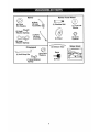 7
7
-
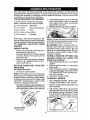 8
8
-
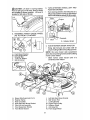 9
9
-
 10
10
-
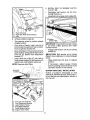 11
11
-
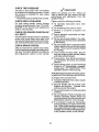 12
12
-
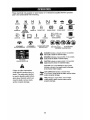 13
13
-
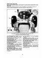 14
14
-
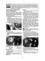 15
15
-
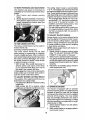 16
16
-
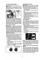 17
17
-
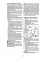 18
18
-
 19
19
-
 20
20
-
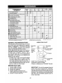 21
21
-
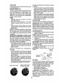 22
22
-
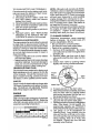 23
23
-
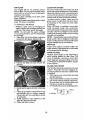 24
24
-
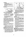 25
25
-
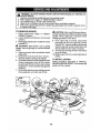 26
26
-
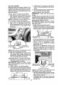 27
27
-
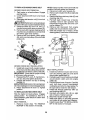 28
28
-
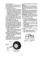 29
29
-
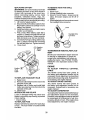 30
30
-
 31
31
-
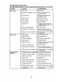 32
32
-
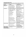 33
33
-
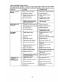 34
34
-
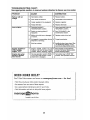 35
35
-
 36
36
-
 37
37
-
 38
38
-
 39
39
-
 40
40
-
 41
41
-
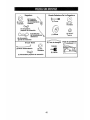 42
42
-
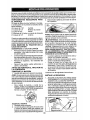 43
43
-
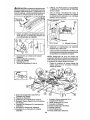 44
44
-
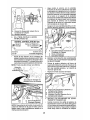 45
45
-
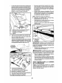 46
46
-
 47
47
-
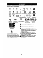 48
48
-
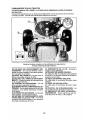 49
49
-
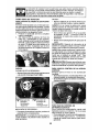 50
50
-
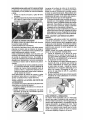 51
51
-
 52
52
-
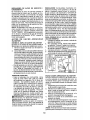 53
53
-
 54
54
-
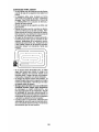 55
55
-
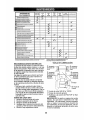 56
56
-
 57
57
-
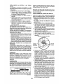 58
58
-
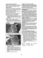 59
59
-
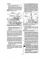 60
60
-
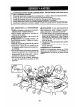 61
61
-
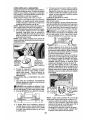 62
62
-
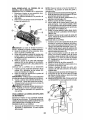 63
63
-
 64
64
-
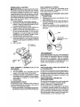 65
65
-
 66
66
-
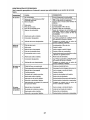 67
67
-
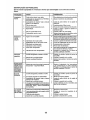 68
68
-
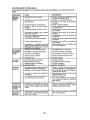 69
69
-
 70
70
-
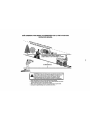 71
71
-
 72
72


Craftsman 28947 - GT 5000 26 HP/54" Garden Tractor Manual de usuario
- Categoría
- Cortadoras de césped
- Tipo
- Manual de usuario
En otros idiomas
Documentos relacionados
-
Craftsman 917289903 El manual del propietario
-
-
-
-
-
-
-
-
-