

L
E
V
E
L
P
A
D
R
IM
LEVEL
PAD
RIM
LEVEL
PAD
RIM

If the following trouble occurs when the Real Head Pad is used, please check the following
points before asking your dealer for assistance.
INTRODUCTION
Thank you for purchasing the YAMAHA Real Head Pad RHP80/100/120/120SD. The
YAMAHA Real Head Pad series was developed as a trigger pad for use with an elec-
tric drum system. The pads utilize Remo Coated Ambassador heads. This system
delivers a richer, closer to acoustic feeling that extends greater expressive potential to
the drummer. Just like a real, high quality acoustic drum, the shell is made of birch
then covered with a clear finish.
To get the most out of your YAMAHA Real Head Pad Series, please read this manual
carefully. After reading, please keep it in a safe place for future reference.
OWNER’S MANUAL
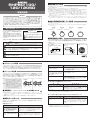
Before setup, please make sure that all of the items listed below are present and accounted
for. If anything is missing, please contact the dealer from whom you purchased the unit.
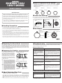
Gray Flat Cushion
(Bottom)
Yellow Cushion
(Top)
■ About Replacing Worn Parts
(Rubber Hoop Cover, Cushions, etc.)
• This product uses parts (drum head, cushion, rubber hoop cover, Output Level Adjustment
knob, output jacks, etc.) that will wear or deteriorate over time. How these parts wear or
deteriorate will depend upon the environment, length of time, etc., in which the device is
used.
• Please ask the dealer from whom you purchased the device about replacing worn parts.
• Do not disassemble (except for when replacing the head or a cushion as described in this manual) or alter the
product. Doing so may result in damage or deterioration to the product.
• Do not step on or place heavy objects on the product. It may result in damage.
• Do not use or keep the product in places with extremely high temperature (places in direct sunlight, close to a
heater, in a closed car, etc.) or damp (bathroom, outside on a rainy day, etc.). It may result in deformation,
discoloration, damage or deterioration.
• To clean the product, please wipe with a soft cloth or a damp cloth that has been wrung out thoroughly. If the
product is soiled, use a neutral detergent on a cloth then wipe with a damp cloth that has been wrung out
thoroughly to remove any remaining detergent. Do not use benzine, thinner or alcohol as it may result in
discoloration or deformation. Also pay close attention so as not to let the water and detergent come into
contact with the cushions used in the product, it may result in deterioration.
• When connecting or disconnecting cables, make sure to hold the cable by the plug. Also, make sure heavy or sharp
objects are not placed upon the cable. If excessive force is placed on the wire, it may result in the wire breaking.
• Pad Units (RHP80/100/120/
120SD) x1
• Stereo Phone Cable
(3m) x1
■ Handling Precautions
■ Inside This Package
Pad Unit
NOTE : When you use the corrugated cushion, put the
yellow cushion that was installed at the factory
on the bottom, then the corrugated cushion on
top with the corrugated side of the cushion in
contact with the drum head (in this case the
flat, gray cushion is not needed).
NOTE : When the corrugated cushion is not used, make
sure the other cushions are positioned in the
same manner as when the unit was shipped
from the factory, with the flat, gray cushion on
the bottom and the yellow cushion in contact
with the drum head. If the cushions are
reversed, it may result in deterioration of the
cushions.
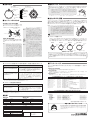
■ What is Explained in this Manual
• The RHP80/100/120 are tom type (8”/10”/12”) trigger pads with rod clamps that can be
attached to a tom stand or rack.
• The RHP120SD is a 12” snare drum type trigger pad. It can be set on a snare stand
(YAMAHA:SS642, etc.).
RHP80 (8”)
RHP120SD (12”)
RHP120 (12”)
RHP100 (10”)
Rod Clamp Rod Clamp Rod Clamp
LEVEL
PAD
RIM
Drum Head
Rod Clamp
(The RHP120SD is not equipped with this clamp)
Clamp Bolt
(The RHP120SD is not
equipped with this bolt)
Hoop
Tuning Bolt
Lug
Shell
OUTPUT Jack
Bottom Cover
• Corrugated
Cushion x1
■ Replacing the Cushion
Like acoustic drums, the Real Head Pad’s drum head will wear over time. When it is time to
change the old head with a new one, please do so on your own. We recommend the use of
Remo Coated Ambassador 8", 10" and 12" drum heads, but you may use any other head that
you prefer. Just keep in mind that depending upon the drum head you use, the feel, sound,
output, etc. may be slightly different.
For sensing and sound deadening purposes,
the Real Head Pads utilize a cushion that pro-
vides support to the entire drum head from
within the pad. You can use the supplied cor-
rugated cushion in place of the cushion that
was installed at the factory. Use of the corru-
gated cushion offers a firmer feeling head.
Select the best cushion according to the type
of drum head you use.
■ Replacing the Drum Head
■ Troubleshooting
●
Multiple sounds are produced when the pad is struck once (Double Trigger).
Yellow Cushion
(Bottom)
Corrugated Cushion
(Top)
■ Part Names
The plug with the
two black rings
When the corrugated cushion is not used.
(As shipped from the factory)
When the corrugated cushion is used.
Rod Clamp
(The RHP120SD is not
equipped with this clamp)
● No Sound, Volume is Low
Problem
Is the Real Head Pad’s OUTPUT
jack properly connected to the In-
put jack on the DTXTREME/DTX/
DTXPRESS with the supplied ste-
reo phone cable (the plug with two
black rings)?
Is the Real Head Pads Output
LEVEL Adjustment set too low?
Is the drum head on the real head
pad too loose?
Is the DTXTREME/DTX/DTXPRESS
properly connected to a pair of
headphones or the external audio
device?
Is the DTXTREME/DTX/
DTXPRESS properly setup?
What to check.
If the pad is connected with a monaural phone cable
(the plug with one black ring), the rim shot s o u n d
will not be produced. Also, if the Real Head Pad is con-
nected to an INPUT number on the DTX/DTXPRESS
that is not capable of producing rim shots, the sound
will not be produced. (Refer to the “Connections” sec-
tion above.)
If the level is set too low, the signal level sent when the pad
is hit will be very low so, the DTXTREME/DTX/DTXPRESS
will not be able to produce sufficient volume from this low
level signal.
If the drum head is too loose, the output from the rim sensor
may be reduced. Use a tuning key to adjust the tension on the
head. (Refer to the previous “Setting Up” section.)
Check connections, power switches or volume settings
on the external devices.
Check if the volume setting assigned to each of the
DTXTREME/DTX/DTXPRESS’s INPUT numbers is not
set too low (refer to the “To Increase the Sound Vol-
ume” section above).
Also, check to see if the headphone volume etc. is not
set too low.
Problem
Is the Real Head Pad’s Output
LEVEL adjustment knob set too
high?
What to check.
If the Output LEVEL knob is set too high, the large sig-
nal remains for a longer time causing the DTXTREME/
DTX/DTXPRESS to produce multiple triggers. Use the
previously explained Output LEVEL adjustment to set
the level to a proper level.
❇ If the double triggers continue even after you have tried the solutions listed above, use the DTXTREME/DTX/
DTXPRESS “Self Rejection” function to control the problem. Refer to the Owner’s Manual supplied with the
DTXTREME/DTX/DTXPRESS for more information.

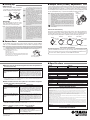
■ Setting Up
Insert the Tom Holder (6-sided), on a rack stand
or tom stand, into the Rod Clamp attached to
the Pad, and tighten the Clamp Bolt firmly.
(RHP80/100/120)
* Only the following inputs can be used.
DTXTREME: INPUT 1-8, 9/10-15/16
DTX: INPUT 9/10, 11/12
DTXPRESS: INPUT 9/10
Since other INPUTS are designed for use with pad trigger/rim switch
type pads (TP-80S, etc.), only the pad will be able to produce sound
when a Real Head Pad is connected.
Controls the trigger output level produced by the Real Head Pads. Output produced by either the
pad section (the drum head section) or rim section (rim shot) can be controlled individually. Turn
the LEVEL adjustment knob to the right (+) to increase the level. Turn to the left (-) to decrease
the level. Adjust the level according to the amount of strength you use when playing the pad and
rim, the required dynamic range, or specific needs regarding the devices that you use.
NOTE : When the Real Head Pad is used with the DTXTREME/DTX/
DTXPRESS, the value on the Input Level display, found in the
Trigger Edit Mode’s [PAD GAIN] page, should be set to a value
somewhere between 90% and 95% when the pad is struck at ff (the
rim should be set the same for rim shots). For more information,
please refer to the “Owner’s Manual” supplied with your DTXTREME/
DTX/DTXPRESS.
If the Output LEVEL is set too high, the dynamic range may be
reduced, or problems such as double triggers (when a single stroke
produces multiply triggered sounds), and cross talk (hitting the pad
causes the sound assigned to the rim to be produced or vice versa)
may occur.
: Do not put excessive pressure on the level adjustment knob, it may
result in damage.
■ Specifications
Pad Diameter 8 inches
Size (including protrusions)
237(W) x 291(D) x 140(H)mm
Weight 1,740g
Includes Rod Clamp
● RHP80
Pad Diameter 10 inches
Size (including protrusions)
299(W) x 342(D) x 140(H)mm
Weight 2,080g
Includes Rod Clamp
● RHP100
Pad Diameter 12 inches
Size (including protrusions)
350(W) x 392(D) x 140(H)mm
Weight 2,390g
Includes Rod Clamp
● RHP120
Pad Diameter 12 inches
Size (including protrusions)
350(W) x 350(D) x 94(H)mm
Weight 1,990g
● RHP120SD
Sensor System Dual Trigger Type (Pad/Rim)
Control Output LEVEL Volume x2 (Pad/Rim)
Output Jack Standard Stereo Phone Jack (stereo)
Accessories Stereo Phone Cable (3m) x1, Corrugated Cushion x1, Owner’s Manual (this booklet) x1
* Improvements may result in a change in the specifications and/or design of the product without notice.
● For All types
Tom Holder
Rod Clamp
Insert
Clamp Bolt
NOTE : When attaching the Real Head Pads to a rack
system, we recommend that either the YAMAHA
Rack System RS100 or RS95 be used. Using a
ball clamp type tom holder like the RS100
allows the attachment of large pads like the
RHP120. A cylinder type tom holder like the
RS95 allows the attachment of lighter pads up
to the RHP80. When a large pad such as the
RHP100/120 is attached to the RS95, we
recommend that the tom holder TPCL100
(optional) be used. The RS60 and RS80 may
not provide adequate support for the Real Head
Pads. If you already own the RS80 rack
(RHP120SD)
The snare drum pad can setup on a snare
drum stand (YAMAHA: SS642, etc.) in the
same manner as a normal snare drum.
LEVEL
Adjustment
Knob
LEV
EL
PAD
RIM
LEVEL
PAD
RIM
Sensor Location
Sensor LocationSensor Location
Sensor Location
■ Output Level (LEVEL) Adjustment
Use the supplied stereo phone cable to connect the pad’s output jack to the input (SNARE,
TOM1, etc.) of the DTXTREME/DTX/DTXPRESS. Connect the cable’s L-shaped plug to the pad.
NOTE : The RHP80/100/120/120SD Real Head Pads are dual trigger type electronic drum pads. Both the pad (the
drum head section) and the rim (the hoop section around the head that is used for rim shots) are individually
equipped with trigger sensors. A separate sound can be assigned to the rim to allow for rim shots *.
■ Connections
● About Rim Shot Sensitivity
The locations of the RHP80/100/120/120SD’s trigger sensors are shown in the illustration.
The highest sensitivity can be found in the direct vicinity of the sensor and will decrease as
you move away from the sensor. If you are going to use rim shots, we recommend that the
area of highest sensitivity be placed in an optimum position when setting up the pad.
To Increase the Sound Volume
To change the volume of the sound assigned to individual pads when the Real Head Pads are used
with the DTXTREME/DTX/DTXPRESS, first adjust the Output LEVEL as described previously,
then use the (VOICE) EDIT Mode to set the volume on the DTXTREME/DTX/DTXPRESS. Please
refer to the “Owner’s Manual” supplied with your DTXTREME/DTX/DTXPRESS.
SPECIAL MESSAGE SECTION
NOTICE: Service charges incurred due to a lack of knowledge relating to how a function or effect works (when the unit is operating as designed) are not covered by the
manufacturer’s warranty, and are therefore the owners responsibility. Please study this manual carefully and consult your dealer before requesting service.
ENVIRONMENTAL ISSUES: Yamaha strives to produce products that are both user safe and environmentally friendly. We sincerely believe that our products and the
production methods used to produce them, meet these goals. In keeping with both the letter and the spirit of the law, we want you to be aware of the following:
Battery Notice: This product MAY contain a small non-rechargeable battery which (if applicable) is soldered in place. The average life span of this type of battery is
approximately five years. When replacement becomes necessary, contact a qualified service representative to perform the replacement.
This product may also use “household” type batteries. Some of these may be rechargeable. Make sure that the battery being charged is a rechargeable type and that
the charger is intended for the battery being charged.
When installing batteries, do not mix batteries with new, or with batteries of a different type. Batteries MUST be installed correctly. Mismatches or incorrect installation
may result in overheating and battery case rupture.
Warning: Do not attempt to disassemble, or incinerate any battery. Keep all batteries away from children. Dispose of used batteries promptly and as regulated by the
laws in your area. Note: Check with any retailer of household type batteries in your area for battery disposal information.
Disposal Notice: Should this product become damaged beyond repair, or for some reason its useful life is considered to be at an end, please observe all local, state, and
federal regulations that relate to the disposal of products that contain lead, batteries, plastics, etc. If your dealer is unable to assist you, please contact Yamaha directly.
NAME PLATE LOCATION: The name plate is located on the bottom of the product. The model number, serial number, power requirements, etc., are located on this plate.
You should record the model number, serial number, and the date of purchase in the spaces provided below and retain this manual as a permanent record of your purchase.
Model Serial No.
Purchase Date
PLEASE KEEP THIS MANUAL
system, adding the VK80 Rack Reinforcement
Kit (optional) will increase the strength of the
rack to that of the RS95.
NOTE : Drum head tension can be adjusted by
tightening or loosening the tuning bolts on the
hoop with a tuning key.However, there will be
no change in the tone produced by the
DTXTREME/DTX/DTXPRESS, etc.
: Make sure the pads are properly setup on the
rack or stand. If the clamp bolts, etc. are not
tightened sufficiently, the pad may fall off
resulting in injury. Also, if the rack or stand is
not setup on a flat surface, the rack or stand
may overturn resulting in injury.
NOTE : Please make sure that head tension is even all
the way around the head. Uneven tension may
produce wrinkles, which may shorten the life of
the drum head.
NOTE : Make sure the drum head is tightened within a
proper range. Over tightening may result in
damage to the drum head, shell, etc. An overly
loosened head may result in a shorter life of
the drum head, cushion, or noise. Also, when
the head is too loose a metallic noise may
occur when playing rim shots, likewise, the
output from the rim sensor may be reduced and
the sound produced by the DTXTREME/DTX/
DTXPRESS may be reduced or not sound at
all when playing rim shots. The head may also
become loose over time, so occasionally
retighten the head.
● When the pad is hit, the sound assigned to the rim is also produced, or
vice versa (cross talk).
❇
If the cross talk continues even after you have tried the solutions listed above, use the DTXTREME/DTX/DTXPRESS
“Specified Rejection” function to control the problem (can be used on the following channels DTXTREME: INPUTS 9/
10-15/16, DTX: INPUTS 9/10, 11/12, DTXPRESS: INPUT 9/10). Refer to the Owner’s Manual supplied with the
DTXTREME/DTX/DTXPRESS for more information.
Problem
Is the Real Head Pad’s Output
LEVEL Adjustment knob set too
high?
What to check.
If the rim’s Output LEVEL knob is set too high, sympa-
thetic vibrations produced when the pad is hit may be trans-
mitted through the shell, etc. and picked up by the sensor
located in the rim which in turn causes the sound assigned
to the rim to be produced. Use the previously explained
Output LEVEL Adjustment to set the level to a proper level.
● When mounted on the rack and a pad is hit, a sound that is assigned to
another pad is also produced (cross talk).
❇ If the cross talk continues between other pads, even after you have tried the solutions listed above, use the
DTXTREME/DTX/DTXPRESS “Specified Rejection” function to control the problem. Refer to the Owner’s Manual
supplied with the DTXTREME/DTX/DTXPRESS for more information.
Problem
Is the rack system’s strength ad-
equate, or are sections of the rack
loose?
Is the Output LEVEL Adjustment
knob on each of the pads con-
nected to the rack system set too
high?
What to check.
If the clamp bolts, etc. are not tightened firmly when the
rack is assembled, the unstable section of the rack will
move about when the pad is hit. Vibrations are then trans-
mitted to sensors in the other pads resulting in other
sounds being produced. Please make sure that the rack
or stand is assembled firmly.
If the Output LEVEL knob on any of the pads is set too
high, sympathetic vibrations produced when another pad
is hit may be transmitted through the rack pipe, etc. and
picked up by the pad’s trigger sensor which in turn causes
the sound assigned to the pad to be produced. Use the
previously explained Output LEVEL Adjustment and set
the level to a proper level.
● When a rim shot is played, a metallic noise is produced.
For more information on the problems listed above and other problems, please refer to the “Owner’s Manual” supplied with
the DTXTREME/DTX/DTXPRESSS. If you can not solve the problem on your own, please contact the dealer from whom you
purchased the device.
Problem
Is the drum head on the Real Head
Pad too loose?
What to check.
When the drum head is too loose, a metallic noise may
be produced when a rim shot is played.
Use the tuning key to adjust head tension. (Refer to the
previous “Setting Up” section.)
3m Cable with Standard
Phone Plug (Stereo)
Connect
OUTPUT Jack
Location
OUTPUT Jack
Location
OUTPUT Jack
Location
OUTPUT Jack
Location
-
 1
1
-
 2
2
-
 3
3
-
 4
4


en otros idiomas
- français: Yamaha RHP80 Le manuel du propriétaire
- italiano: Yamaha RHP80 Manuale del proprietario
- English: Yamaha RHP80 Owner's manual
- Deutsch: Yamaha RHP80 Bedienungsanleitung
- русский: Yamaha RHP80 Инструкция по применению
- Nederlands: Yamaha RHP80 de handleiding
- português: Yamaha RHP80 Manual do proprietário
- dansk: Yamaha RHP80 Brugervejledning
- polski: Yamaha RHP80 Instrukcja obsługi
- čeština: Yamaha RHP80 Návod k obsluze
- svenska: Yamaha RHP80 Bruksanvisning
- 日本語: Yamaha RHP80 取扱説明書
- Türkçe: Yamaha RHP80 El kitabı
- română: Yamaha RHP80 Manualul proprietarului
Artículos relacionados
-
Yamaha KP120 El manual del propietario
-
-
-
-
-
-
Yamaha RHH135 El manual del propietario
-
-
-