
1) Determine desired location for mounting transformer. NOTE:
When deciding location for mounting consideration should be
taken for the requirements listed above.
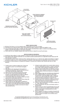
2) Mark position of top portion of the keyhole slot location at
top of transformer and the slot located at bottom.
3) If mounting to a solid surface such as wood, siding, etc;
A) Drill 1/8” diameter pilot holes at positions marked in
Step 2.
B) Drive screws approximately half way into holes.
If mounting to drywall:
A) Drill 1/4” diameter holes at positions marked in Step 2.
B) Push plastic anchors into holes and tap until flush.
C) Drive screws approximately half-way into plastic
anchors.
4) Slip large portion of keyhole over head of top screw and allow
transformer to slide down, making sure bottom slot is behind
head of bottom screw.
5) Tighten screws until transformer is secure.
6) Split 12/2. 10/2, or 8/2 cable approximately 3”, and strip 1/2”
insulation off each wire. 12/2. 10/2, and 8/2 cable is the
heavy black cable which all Kichler
®
12-volt low voltage
lighting fixtures will be connected.
(Reference above for description and part numbers).
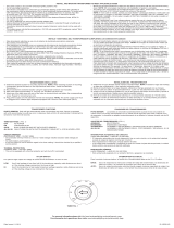
7) On the bottom of the terminal block push one bare wire into
the hole marked “COM” and tighten the corresponding screw
on terminal block face until wire is secure. See chart for
terminal screw tightening specification.
8) For optimum light output, the voltage at the lamp socket
should range between 10.8 and 12 volts for incandescent
products. Most Kichler
®
LED products operate optimally
from 9-15V.
For more information on voltage drop, consult the Kichler
Landscape Lighting Catalog or contact your local Kichler
distributor.
9) Push remaining bare wire into the hole marked 15V on
bottom of terminal block and tighten the corresponding
screw on terminal block face until wire is secure.
• Thispowersupplyisforusewithlandscapelightingsystems
only.
• Donotsubmergetransformer.
• Thisdeviceisacceptedasacomponentofalandscape
lighting system where the suitability of the combination shall
be determined by National Electric Code or local authorities
having jurisdiction.
• WARNING: Risk of electric shock, use only with low voltage
landscape fixtures and accessories. DO not use with swimming
pool or spa lighting fixtures.
• Donotconnecttwoormorepowersuppliesinparallel.
• Suitableforindoororoutdooruse.
• Foruseindwellingsonlywithprovidedconduitadapterplate.
• NationalElectricalCoderequiresthatwiringwhereconcealed
or extended through a building wall must be enclosed in
conduit.
• Transformershouldbemountedclosetopowersource.
Extension cords should not be used with this unit.
• WARNING: (for Power Supply Cord connected POWER UNIT)
RISK OF ELECTRIC SHOCK. Install power unit 5 feet (1.5m) or
more from the pool, spa, or fountain where the power unit is
installed (a) indoor within 10 feet (3.0m) of a pool, spa, or
fountain, or (b) outdoor, connect power to unit to a receptacle
protected by a GFCI.
• Thisoutdoorpowerunitshallbeconnectedtoa115/120volt
covered GFCI receptacle marked “Wet Location” while in use.
• Mounttherain-tighttransformeratleastonefootabove
ground level with the wire terminals facing down. NOTE: Do
not energize transformer until installation of system is complete.
• Directburialratedwireistobeburiedaminimumof6”
(152mm) beneath the surface of the ground.
NOTE: If additional Direct Burial wire is needed, contact your
local Kichler
®
landscape distributor.
•8GAwirecanbepurchasedinlengthof250’(76M),
15503-BK.
•10GAwirecanbepurchasedinlengthof250’(76M),
15504-BK.
•12GAwirecanbepurchasedinlengthsof100’(30M),
15501-BK;250’(76M),15502-BK;500’(152M),15505-BK;and
1000’(304M),15506-BK.
• Finding Transformer Load: Low voltage systems require the
use of a transformer to reduce standard 120-VOLT power from
your home to 12-VOLTS. To determine the transformer size
you will need, add up the wattages of all lamps you plan to
use. Select a transformer that matches as closely as possible
to the total lamp wattage. For example, if you have 11 fixtures
all rated at 24.4 watts, you will need a 300 watt (VA) transformer
(11 x 24.4 = 268.4 watts). Generally, the total lamp load should
not be less than one-third the transformers wattage rating, nor
exceed its maximum wattage capacity. If your total wattage is
too high, either divide the load between two transformers, or
use a more powerful transformer.
This instruction sheet covers the installation of the following Kichler
®
Transformers: 15PR75SS/15PL75XX. Read these instructions care-
fully before installing this unit.
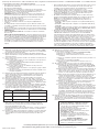
CIRCUIT BREAKER
(SECONDARY SIDE - 15 VOLT SIDE)
•Circuitbreakerwilltripifthereisashort
or if total wattage installed exceeds rated
wattage per circuit.
•Toresetbreaker,ipswitchto‘OFF’then
backto‘ON’position.
•Iftheunitcyclesonandoffwithoutregard
to the timer setting, it should be checked
by a qualified service person.
THERMAL PROTECTION
(PRIMARY SIDE - 120 VOLT SIDE)
•Thisunitisequippedwithathermal
protector and will shut off if overheated.
INSTALLATION INSTRUCTIONS
Date Issued: 8/31/12 IS-15PR75-US
10) Above terminal blocks is a receptacle and a short power cord.
• Ifusingplug-intimer(15556WH/15557BK):
A) Plug timer into receptacle.
B) Plug short power cord into timer
` C) Set timer following instructions provided with timer.
• Ifnotusingplug-intimer:
A) Plug short power cord into receptacle.
11) Optional Photo control Installations:
A) Make sure power is off and transformer is NOT plugged
into an electrical outlet. NOTE: No splice is required,
transformer is equipped with jumper connector.
B) Open front cover of the transformer case by lifting
the cover up. Locate and disconnect the white jumper
connector inside the housing. *Save the jumper connector
with these instructions for possible future use.
C) Remove one (1) of the 7/8” diameter knockouts on
the side of the transformer and push the photo control
white connector through the knockout hole. Inside the
housing, slide the spacer and star nut over the white
connector and thread it on to the photo control and
tighten.
D) Plug photo control white connector into the housing
connector. Insure that the side latch locks the connectors.
E) Locate transformer and position photo control so that
no light will shine on the cell. It will cause the photo
control to cycle on and off. *In the unlikely event that
the photo control should fail, the lighting fixtures will
remain on, even in the daytime. If this should happen,
follow these instructions and remove the defective
photo control and place the jumper connector in its place.
12) Plug power supply cord into standard 115/120 volt receptacle.
NOTE: The power supply cord must be plugged into a weather
tight receptacle equipped with a Ground Fault Interrupter
(GFCI).
For warranty information please visit: http://www.landscapelighting.com/portal/warranty_page
Para informacion de la garantia por favor visite: www.landscapelighting.com/portal/warranty_page
Wire Sizes
#12
#10
#8
Max. no. of conductors
8
4
1
Tightening Torque
3.6-4.0 N-m (32-35 lb-in)
3.6-4.0 N-m (32-35 lb-in)
4.1-4.5 N-m (36-40 lb-in)

• Estaalimentacióneléctricaessolamenteparausarconlossistemas
deiluminaciónornamental.
• Nosumerjaeltransformador.
• Estedispositivoseconsiderauncomponentedeunsistemade
iluminaciónornamental,dondelaefectividaddelacombinaciónserá
determinadaporelCódigodeElectricidadNacionaloporlas
autoridadeslocalesconjurisdicciónallí.
• ADVERTENCIA:Riesgodechoqueseléctricos,usesolamentecon
accesoriosyartefactosdeiluminaciónornamentaldebajatensión.
NOuseconartefactosdeiluminaciónparamanantialesdeagua
mineral, de piscinas o albercas.
• Noconectedosomásalimentacioneseléctricasenparalelo.
• Aptoparausointerioroexterior.
• Parausoenviviendassolamenteconunaplacaadaptadorade
conducto.
• ElCódigoEléctricoNacionalrequierequeelcableadocuandoesté
escondidooextendidoatravésdelapareddelediciovayaencerrado
en un conducto.
• Eltransformadordebeestarmontadocercadelafuentedealimentación
eléctrica.Loscordonesdeextensiónnodebenusarseconestaunidad.
• ADVERTENCIA
(paralaUNIDADDEPOTENCIAconectadaalCordóndesuministro
de potencia)
RIESGO DE CHOQUE ELÉCTRICO. Instale la unidad de potencia a 5
pies(1.5m)omásdeunapiscina(alberca),manantialdeaguamineral
ofuentedondelaunidaddepotenciaestéinstalada(a)bajotechodentro
de los 10 pies (3.0m) de una piscina (alberca), manantial de agua
mineral o fuente, o (b) al aire libre, conecte el suministro de potencia a
launidadaunreceptáculoprotegidoporuninterruptordecircuito
accionadoporpérdidaatierraaccidental(GFCI,porsussiglasen
inglés).
• Estaunidaddealimentacióneléctricaalairelibredebeestarconecta
da a un tomacorriente con interruptor de circuito accionado por
pérdidaatierraaccidentalcubierto,de115/120voltios,marcado
“LugarMojado”(“WetLocation”),mientrasestéenuso.
• Monteeltransformadorestancoalalluviaporlomenosaunpie
arriba del nivel del terreno con los terminales de alambre mirando
hacia abajo. NOTA: No energice el transformador hasta que la
instalacióndelsistemaestécompleta.
• Elalambreclasicadoparasoterradodirectosedebeenterrarun
mínimode6pulgadas(152mm)debajodelasuperciedelterreno.
NOTA: Si necesita alambre de soterrado directo adicional, co
muníqueseconsudistribuidorlocalKichler®deproductosde
jardineríaornamental.
•Elalambrecalibre8puedecomprarseenlongitudde250’(76m.),
15503-BK
•Elalambrecalibre10puedecomprarseenlongitudde250’(76m.),
15504-BK
•Elalambrecalibre12puedecomprarseenlongitudesde75’(22m.),
15550-BK;100’(30m.),15501-BK;250’(76m.),15502-BK;500’(152m.),
15505-BK;y1000’(304m.),15506-BK.
• Determinelacargadeltransformador:Lossistemasdebajatensión
requieren el uso de un transformador para reducir la potencia de
120VOLTIOSestándardelacorrientedesucasaa12VOLTIOS.
Paradeterminareltamañodeltransformadorquenecesitaráusted,
sumelosvatajesdetodaslaslámparasqueplaneausar.Seleccione
un transformador que coincida tan cerca como sea posible con el
vatajetotaldelaslámparas.Porejemplo,sitiene11artefactos
clasicadosa24.4vatioscadauno,ustednecesitaráuntransformador
de 300 vatios (VA) (11 x 24.4 = 268.4 vatios). Generalmente, la carga
totaldelaslámparasnodebesermenordeunterciodelacapacitad
envatiosdeltransformador,niexcedersumáximacapacidaden
vatios. Si el vataje total es demasiado alto, entonces divida la carga
entre2transformadoresobienuseuntransformadormáspotente.
EstahojadeinstruccionescubrelainstalacióndelossiguientestransformadoresKichler
®
: 15PR75SS/15PL75XX. Lea cuidadosamente
estas instrucciones antes de instalar la unidad.
1) Determine el lugar deseado donde montar el transformador. NOTA:
Cuandodecidaellugardondemontar,sedebetenerenconsideración
los requisitos de la lista de arriba.
2) Marquelaposiciónenlaporciónsuperiordellugardelaranuradel
agujero de deslizar, en el tope del transformador y la ranura localizada
en la parte inferior.
3) Sisemontaenunasuperciesólidacomomadera,revestimientode
pared o chapa, etc.;
A) Perforeagujerospilotode1/8”dediámetroenlasposiciones
marcadas en el paso 2.
B) Instale los tornillos aproximadamente hasta la mitad en los
agujeros perforados.
Si monta en una pared sin mortero:
A) Perforeagujerosde1/8”dediámetroenlasposiciones
marcadas en el paso 2.
B) Pongalosanclajesdeplásticoenlosagujerosygolpeehasta
queesténaras.
C) Instale los tornillos aproximadamente hasta la mitad en los
anclajesdeplástico.
4) Resbalelaporcióngrandedelagujerodedeslizarsobrelacabezaen
el tope del tornillo y deje que el transformador se deslice hacia
abajo, asegurándosedequelaranurainferiorestédetrásdela
cabeza del tornillo inferior.
5) Aprietelostornilloshastaqueeltransformadorestésujetado.
6) Parta aproximadamente 3” el cable de 12/2, 10/2 o de 8/2, y pele
1/2” del aislamiento de cada cable. El cable calibre 12/2, 10/2 y 8/2
eselcablenegroduroalqueiránconectadoslosartefactosde
iluminacióndebajatensiónKichler®de12voltios.(Reérasearriba
paraladescripciónynúmerodelaspiezas).
7) En el fondo de la regleta de terminales empuje un alambre desnudo
en el agujero marcado “COM” y apriete el tornillo correspondiente en
lacaradelaregletadeterminaleshastaqueelalambreesté
sujetado.Vertablaparaespecicacióndetorquenaldeltornillo.
8) Paralasalidaóptimadeluz,elvoltajeenelsocketdelalámpara
debe estar en el rango de 10.8 y 12 voltios para los productos
incandescentes.LamayoríadelosproductosLEDdeKichler®
funcionanóptimamentede9-15V.
Paramásinformaciónsobrelacaídadevoltaje,consulteelCatálogo
deIluminacióndePaisajesdeKichlerocontacteasudistribuidor
local Kichler.
9) Introduzca el cable sin revestimiento restante por el orificio marcado
15V en la parte inferior del bloque de terminales y apriete el tornillo
correspondienteenelfrentedelbloquehastaqueelcableesté
seguro.
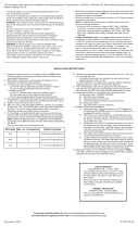
INTERRUPTOR AUTOMÁTICO
(LADO SECUNDARIO – LADO DE 15 VOLTIOS)
• Elinterruptorautomáticodispararásihayun
cortocircuito o si la vataje total instalado excede
el vataje nominal por circuito
•Parareposicionarelinterruptorautomático,
basculeelinterruptoralaposición
“ APAGADO”(“OFF”)yluegovuelvaalaposición
“ENCENDIDO” (“ON”).
• Silaunidadcicla,empujarencendiendoy
apagándosesintenerencuentaelajustedel
cronizador, la unidad debe verificar una persona
de servicio competente.
PROTECCIÓN TÉRMICA
(LADO PRIMARIO – LADO DE 120 VOLTIOS)
• Estaunidadestáequipadaconunprotector
térmicoyseapagarásiserecalienta.
INSTRUCCIONES DE INSTALACIÓN
IS-15PR75-US
10) Arribadelasregletasdeterminaleshayuntomacorrienteyuncordón
dealimentacióneléctricacorto.
• Siseusauncronizadorenchufable(15556WH/15557BK):
A) Enchufe el cronizador en el tomacorriente.
B) Enchufeelcordóndealimentacióneléctricacortoenel
cronizador.
C) Ajuste el cronizador siguiendo las instrucciones provistas con
el mismo.
• Sinoseusauncronizadorenchufable:
A)Enchufeelcordóndealimentacióneléctricacortoenel
tomacorriente.
11)Opcionallasinstalacionesdecontrolconcélulafotoeléctrica:
A) Asegúresedequelaalimentacióneléctricaestéapagadayel
transformadorNOestáenchufadoenuntomacorriente.NOTA:
Nosenecesitaempalme;eltransformadorestáequipadocon
un conector de cable de puente.
B) Abra la tapa frontal de la caja del transformador levantando la
tapa. Localice y desconecte el conector del cable de puente
blanco dentro de la cabina. Guarde el conector del cable de
puente con estas instrucciones para un posible uso futuro.
C) Quiteuno(1)delosagujerosciegosde7/8”dediámetroenel
costado del transformador y empuje el conector blanco de
controldecélulafotoeléctricaatravésdelagujerociego.
Dentro de la cabina, deslice el espaciador y la tuerca estrellada
sobreelconectorblancoyatornílleloenelcontroldecélula
fotoeléctricayapriete.
D) Enchufeelconectorblancodecontroldecélulafotoeléctricaenel
conectordelacabina.Asegúresedequelosenganches
laterales traben los conectores.
E) Localiceeltransformadorycoloqueelcontroldecélula
fotoeléctricademodoquelaluznobrilleenlacélula.Esohará
queelcontroldelacélulafotoeléctricacicleencendiendoy
apagándose.Enelcasoimprobabledequeelcontroldecélula
fotoeléctricafallara,losartefactosdeiluminaciónpermanecerán
encendidos,aundurantelashorasdeldía.Siestoocurriera,siga
estasinstruccionesyquiteelcontroldecélulafotoeléctrica
defectuoso y ponga el conector del cable de puente en lugar
del mismo.
12) Enchufeelcordóndealimentacióneléctricaeneltomacorriente
estándarde115/120voltios.NOTA:Elcordóndealimentación
eléctricadebeestarenchufadoenuntomacorrientehermético
equipadoconuninterruptordecircuitoaccionadoporpérdidaa
tierra accidental.
Date Issued: 8/31/12
For warranty information please visit: http://www.landscapelighting.com/portal/warranty_page
Para informacion de la garantia por favor visite: www.landscapelighting.com/portal/warranty_page
Tamaños de
alambre
#12
#10
#8
Cantidad máxima de
conductores
8
4
1
Torque de apriete
3.6-4.0 N-m (32-35 lb-in)
3.6-4.0 N-m (32-35 lb-in)
4.1-4.5 N-m (36-40 lb-in)
-
 1
1
-
 2
2


Kichler Lighting 15PL75AZT Manual de usuario
- Tipo
- Manual de usuario
- Este manual también es adecuado para
en otros idiomas
Artículos relacionados
-
 Kichler Lighting 15CS75SS Manual de usuario
-
Kichler Lighting 15PR100SS Manual de usuario
-
 Kichler Lighting 15pr1200ss Manual de usuario
-
 Kichler Lighting 15072AZT Manual de usuario
-
 Kichler Lighting 15515CBR Manual de usuario
-
 Kichler Lighting 15E60BK Manual de usuario
-
 Kichler Lighting 15826AZT30R Manual de usuario
-
 Kichler Lighting Showscape 12217 Manual de usuario
-
 Kichler Lighting 16131AZT28 Manual de usuario
-
Kichler Lighting 10189BK Manual de usuario


