Legrand Toggle Incandescent Dimmers Guía de instalación
- Tipo
- Guía de instalación

To be installed by a certified electrician or other qualified person.
WARNING – To prevent severe shock or electrocution, always turn power
OFF at the service panel before installing this unit, working on the circuit, or
changing a lamp.
CAUTION – To reduce the risk of overheating and possible damage to other
equipment, do not install incandescent dimmer to control a receptacle, a
fluorescent light, a motor-operated appliance, or a transformer-supplied
appliance.
Do not use dimmer with incandescent lamps whose power requirements
exceeds maximum power (stated in Watts) of the dimmer.
Do not connect dimmer to power source other than 120VAC, 60 Hz only.
Use copper wire only.
DIRECTIONS
1. Disconnect power to circuit by removing fuse or turn circuit breakers OFF
before installing.
2. Remove wall plate and switch mounting screws, pull existing switch from
wall box.
3. Disconnect existing switch from circuit. 3-way installation: Identify the
“COMMON” wire (wire connected to the terminal marked common or odd
colored terminal). For “new” installation identify wire connected to power
source or to the load.
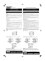
4. Connect dimmer as shown in the installation diagram using #12 or #14
AWG stranded or solid copper conductors. Strip wire using gauge on back
of device.
5. Install dimmer in wall box, with word ‘TOP’ on the strap right side up, using
mounting screws provided.
6. Attach wall plate, then restore power to circuit. NOTE: It is necessary to
remove knob on Short Slide version before attaching wall plate.
NOTE: It is normal for the dimmer to feel warm during operation. A 50W
minimum load is required. Use a separate neutral wire for each phase of a
multiphase system containing a dimmer, and for high power single phase
applications where flickering is present.
DIMMER
MULTIPLE GANGING OF DIMMERS
Any combination of dimmer models and other devices may be ganged
together. Dimmers can be ganged without removing fins. De-rate the
maximum load according to the following table.
MAXIMUM
GANG REDUCTION
LOAD
2 DIMMERS 3+DIMMERS
1000W 700W 650W
Para ser instalado por electricista certificado u otra persona capacitada.
ADVERTENCIA: Para prevenir una sacudida eléctrica severa o electrocución,
siempre CORTE la electricidad en el panel de servicio antes de instalar esta
unidad, trabajar en el circuito, o cambiar una lámpara.
AVISO: Para reducir el riesgo de recalentamiento y posiblemente dañar a
otro equipo, no instale el reductor de luz incandescente para controlar un
receptáculo, una luz fluorescente, un artefacto motorizado, o un artefacto
alimentado por un transformador.
No use el reductor de luz con lámparas incandescentes cuyas requisitos de
potencia exija la potencia máxima (indicada en Wats) del reductor de luz.
No conecte al reductor de luz a otra fuente de potencia que no sea solo
120VAC, 60Hz.
Solo utilice cables de cobre.
INSTRUCCIONES:
1. Corte la electricidad al circuito en el panel quitando el fusible o
APAGANDO el interruptor automático antes de la instalación.
2. Quite la chapa de pared y los tornillos de montura de chucho, hale el
chucho existente de la caja embutida en la pared.
3. Desconecte el chucho existente del circuito. Instalación de tres
direcciones: Identifique el cabe “COMÚN” (el cable conectado al la
terminal marcada “común - common” o la terminal colorada con un color
singular). Para instalación “nueva” identifique el cable conectado al la
fuente de potencia o a la carga.
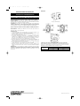
4. Conecte el reductor de luz como mostrado en el diagrama de instalación
utilizando alambre trenzado o sólido #12 o #14 AWG de cobre. Pele el
alambre utilizando la guÌa en la parte trasera del aparato.
5. Instale el reductor de luz en una caja de pared con la palabra “TOP” en la
correa hacia arriba, utilizando los tornillos de montaje proveídos.
6. Fije la chapa de pared, entonces restáurele la corriente al circuito. NOTA:
Es necesario quitarle la perilla en la versión de Deslice Corto antes de fijar
la chapa de pared.
NOTA: Es normal que el reductor de luz se sienta caliente durante su
funcionamiento. Una carga mínima de 50W es requerida. Use un cable neutral
separado para cada fase de un sistema polifásico que tiene un reductor de
luz, y para aplicaciones de una fase de alta potencia donde ocurre centelleo.
REDUCTORES DE LUZ
AGRUPACIONES MÚLTIPLES DE REDUCTORES DE LUZ Y OTROS
APARATOS
Cualquier combinación de modelos de reductores de luz u otros aparatos
pueden ser agrupados. Reductores de luz pueden ser agrupados sin tener
que remover los disipadores. Reduzca la capacidad máxima de acuerdo con
la siguiente tabla.
CAPACIDAD
REDUCCÓN DE AGRUPACIÓN
MÁXIMA
2 REDUCTORES DE LUZ 3+REDUCTORES DE LUZ
1000W 700W 650W
INSTALLATION INSTRUCTIONS
INCANDESCENT DIMMERS
READ AND SAVE THESE INSTRUCTIONS!
Toggle
Single Pole Three Way
INSTALLATION DIAGRAM (wiring is same with each of dimmer types)
INSTRUCCIONES EN ESPAÑOL
LEA Y GUARDE ESTAS INSTRUCCIONES
INSTRUCCIONES DE INSTALACIÓN
REDUCTORES DE LUZ INCANDESCENTE
Volquete
Poste Solo De Tres Direcciones
ESQUEMA DE INSTALACIÓN (El alambrado es el mismo para cada tipo
de reductor de luz)
340609 Rev. B 10/29/03 8:12 AM Page 1
La página se está cargando...
Transcripción de documentos
340609 Rev. B 10/29/03 8:12 AM Page 1 INSTRUCCIONES EN ESPAÑOL INSTALLATION INSTRUCTIONS INSTRUCCIONES DE INSTALACIÓN INCANDESCENT DIMMERS REDUCTORES DE LUZ INCANDESCENTE READ AND SAVE THESE INSTRUCTIONS! LEA Y GUARDE ESTAS INSTRUCCIONES To be installed by a certified electrician or other qualified person. Para ser instalado por electricista certificado u otra persona capacitada. WARNING – To prevent severe shock or electrocution, always turn power OFF at the service panel before installing this unit, working on the circuit, or changing a lamp. ADVERTENCIA: Para prevenir una sacudida eléctrica severa o electrocución, siempre CORTE la electricidad en el panel de servicio antes de instalar esta unidad, trabajar en el circuito, o cambiar una lámpara. AVISO: Para reducir el riesgo de recalentamiento y posiblemente dañar a otro equipo, no instale el reductor de luz incandescente para controlar un receptáculo, una luz fluorescente, un artefacto motorizado, o un artefacto alimentado por un transformador. No use el reductor de luz con lámparas incandescentes cuyas requisitos de potencia exija la potencia máxima (indicada en Wats) del reductor de luz. No conecte al reductor de luz a otra fuente de potencia que no sea solo 120VAC, 60Hz. Solo utilice cables de cobre. INSTRUCCIONES: 1. Corte la electricidad al circuito en el panel quitando el fusible o APAGANDO el interruptor automático antes de la instalación. 2. Quite la chapa de pared y los tornillos de montura de chucho, hale el chucho existente de la caja embutida en la pared. 3. Desconecte el chucho existente del circuito. Instalación de tres direcciones: Identifique el cabe “COMÚN” (el cable conectado al la terminal marcada “común - common” o la terminal colorada con un color singular). Para instalación “nueva” identifique el cable conectado al la fuente de potencia o a la carga. 4. Conecte el reductor de luz como mostrado en el diagrama de instalación utilizando alambre trenzado o sólido #12 o #14 AWG de cobre. Pele el alambre utilizando la guÌa en la parte trasera del aparato. 5. Instale el reductor de luz en una caja de pared con la palabra “TOP” en la correa hacia arriba, utilizando los tornillos de montaje proveídos. 6. Fije la chapa de pared, entonces restáurele la corriente al circuito. NOTA: Es necesario quitarle la perilla en la versión de Deslice Corto antes de fijar la chapa de pared. NOTA: Es normal que el reductor de luz se sienta caliente durante su funcionamiento. Una carga mínima de 50W es requerida. Use un cable neutral separado para cada fase de un sistema polifásico que tiene un reductor de luz, y para aplicaciones de una fase de alta potencia donde ocurre centelleo. CAUTION – To reduce the risk of overheating and possible damage to other equipment, do not install incandescent dimmer to control a receptacle, a fluorescent light, a motor-operated appliance, or a transformer-supplied appliance. Do not use dimmer with incandescent lamps whose power requirements exceeds maximum power (stated in Watts) of the dimmer. Do not connect dimmer to power source other than 120VAC, 60 Hz only. Use copper wire only. DIRECTIONS 1. Disconnect power to circuit by removing fuse or turn circuit breakers OFF before installing. 2. Remove wall plate and switch mounting screws, pull existing switch from wall box. 3. Disconnect existing switch from circuit. 3-way installation: Identify the “COMMON” wire (wire connected to the terminal marked common or odd colored terminal). For “new” installation identify wire connected to power source or to the load. 4. Connect dimmer as shown in the installation diagram using #12 or #14 AWG stranded or solid copper conductors. Strip wire using gauge on back of device. 5. Install dimmer in wall box, with word ‘TOP’ on the strap right side up, using mounting screws provided. 6. Attach wall plate, then restore power to circuit. NOTE: It is necessary to remove knob on Short Slide version before attaching wall plate. NOTE: It is normal for the dimmer to feel warm during operation. A 50W minimum load is required. Use a separate neutral wire for each phase of a multiphase system containing a dimmer, and for high power single phase applications where flickering is present. DIMMER REDUCTORES DE LUZ Toggle Volquete INSTALLATION DIAGRAM (wiring is same with each of dimmer types) Single Pole Three Way MULTIPLE GANGING OF DIMMERS Any combination of dimmer models and other devices may be ganged together. Dimmers can be ganged without removing fins. De-rate the maximum load according to the following table. MAXIMUM LOAD 1000W ESQUEMA DE INSTALACIÓN (El alambrado es el mismo para cada tipo de reductor de luz) GANG REDUCTION 2 DIMMERS 3+DIMMERS 700W 650W Poste Solo De Tres Direcciones AGRUPACIONES MÚLTIPLES DE REDUCTORES DE LUZ Y OTROS APARATOS Cualquier combinación de modelos de reductores de luz u otros aparatos pueden ser agrupados. Reductores de luz pueden ser agrupados sin tener que remover los disipadores. Reduzca la capacidad máxima de acuerdo con la siguiente tabla. CAPACIDAD MÁXIMA 1000W REDUCCÓN DE AGRUPACIÓN 2 REDUCTORES DE LUZ 3+REDUCTORES DE LUZ 700W 650W-
 1
1
-
 2
2


Legrand Toggle Incandescent Dimmers Guía de instalación
- Tipo
- Guía de instalación
en otros idiomas
Artículos relacionados
-
Pass and Seymour LSCL450BK Guía de instalación
-
Legrand Rotary Incandescent Dimmers Guía de instalación
-
Pass and Seymour R1000IV Guía de instalación
-
Legrand TLV603LA Guía de instalación
-
-
-
-
-
Legrand LSCL450W Guía de instalación