Truper ROU-NX3 El manual del propietario
- Categoría
- Herramientas eléctricas
- Tipo
- El manual del propietario

Fixed base
router
ROU-NX3
Code
Applies for:
16686
Model
ROU-NX3
Power
2 Hp
CAUTION Read this manual thoroughly
before using the tool.
ENGLISH
ESPAÑOL
Manual

2
Technical data
Power requirements
General power tool safety warnings
Safety warnings for routers
Parts
Preparation
Start up
Operation
Maintenance
Troubleshooting
Notes
Authorized service centers
Warranty policy
3
3
4
5
6
7
9
10
12
13
14
15
16
ROU-NX3
ENGLISH
CAUTION
Contents
Keep this manual for future references.
The illustrations in this manual are for reference
only. They might be different from the real tool.
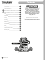
To gain the best performance of
the tool, prolong the duty life,
make the Warranty valid if
necessary, and to avoid hazards
of fatal injuries please read and
understand this Manual before
using the tool.

Power Requirements
3
Technical data
ENGLISH
Tools with double insulation and reinforced insulation are equipped with
a polarized plug (one prong is wider than the other). This plug will only fit in the right way
into a polarized outlet. If the plug cannot be introduced into the outlet, reverse the plug. If
it still doesn’t fit, call a qualified electrician to install for you a polarized outlet. Do not alter
the plug in any way. Both insulation types eliminate the need of both a grounded third
power cord with three prongs or a grounded power connection.
When using an extension cable, verify the gauge is enough for
the power that your product needs. A lower gauge cable will cause voltage drop in the line, resulting in power loss and
overheating. The following table shows the right size to use depending on cable’s length and the ampere capability shown in
the tool’s nameplate. When in doubt use the next higher gauge.
WARNING
WARNING
WARNING
from 0 A and up to 10 A
from 10 A and up to 13 A
from 13 A and up to 15 A
from 15 A and up to 20 A
18 AWG(*)
16 AWG
14 AWG
8 AWG
16 AWG
14 AWG
12 AWG
6 AWG
3 (one grounded)
from 5.9’ to 49.2’ | higher than 49.2’
Ampere
Capacity Number of
Conductors Extension gauge
* It is safe to use only if the extensions have a built-in artifact for over current protection.
AWG = American Wire Gauge. Reference: NMX-J-195-ANCE
When operating power tools outdoors, use a grounded
extension cable labeled “For Outdoors Use”. These extensions are especially designed
for operating outdoors and reduce the risk of electric shock.
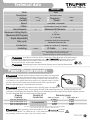
ROU-NX3
16686
60 Hz
Fixed base router
11.3 A 2 HP
Code
Description
Voltage Frequency
PowerCurrent
10000 RPM - 25000 RPM
For bits with 1/4” and 1/2” shanks
Speed
Collets
6” 2"
Base Diameter
1 3/4”
Maximum Cutting Depth
Maximum Bit Diameter
127 V
WARNING
WARNING Avoid the risk of electric shock or severe injury. When the power cable gets damaged
it should only be replaced by the manufacturer or at a Authorized Service Center.
The build quality of the electric insulation is altered if spills or liquid gets into the tool while in use.
Do not expose to rain, liquids and/or dampness.
Before gaining access to the terminals all power sources should be disconnected.
Clase II
16 AWG x2 C with 221 °F insulating
Conductors
Insulating IP 20
IP Grade
Power cord grips used in this product: Type “Y”.
Build quality: Reinforced insulation.
Thermal insulation on motor winding: Class A.
50 minutes work per 20 minutes idle.
Maximum 6 hours per day.
Duty cycle
2” (50 mm)
Maximum Drill Capacity
0 - 2” (50 mm)
Depth Adjustability

4ENGLISH
Work area
Keep your work area clean, and well lit.
Cluttered and dark areas may cause accidents.
Never use the tool in explosive atmospheres, such as in the
presence of flammable liquids, gases or dust.
Sparks generated by power tools may ignite the flammable material.
Keep children and bystanders at a safe distance while operating
the tool.
Distractions may cause loosing control.
Electrical Safety
The tool plug must match the power outlet. Never modify
the plug in any way. Do not use any adapter plugs with
grounded power tools.
Modified plugs and different power outlets increase the risk of electric shock.
Avoid body contact with grounded surfaces, such as pipes,
radiators, electric ranges and refrigerators.
The risk of electric shock increases if your body is grounded.
Do not expose the tool to rain or wet conditions.
Water entering into the tool increases the risk of electric shock.
Do not force the cord. Never use the cord to carry, lift or unplug
the tool. Keep the cord away from heat, oil, sharp edges or
moving parts.
Damaged or entangled cords increase the risk of electric shock.
When operating a tool outdoors, use an extension cord suitable
for outdoor use.
Using an adequate outdoor extension cord reduces the risk of electric shock.
If operating the tool in a damp location cannot be avoided, use
a ground fault circuit interrupter (GFCI) protected supply.
Using a GFCI reduces the risk of electric shock.
Personal safety
Stay alert, watch what you are doing and use common sense
when operating a tool. Do not use a power tool while you are
tired or under the influence of drugs, alcohol or medication.
A moment of distraction while operating the tool may result in personal injury.
Use personal protective equipment. Always wear eye
protection.
Protective equipment such as safety glasses, anti-dust mask, non-skid shoes,
hard hats and hearing protection used in the right conditions significantly
reduce personal injury.
Prevent unintentional starting up. Ensure the switch is in the
“OFF” position before connecting into the power source and /
or battery as well as when carrying the tool.
Transporting power tools with the finger on the switch or connecting power
tools with the switch in the “ON” position may cause accidents.
Remove any wrench or vice before turning the power tool on.
Wrenches or vices left attached to rotating parts of the tool may result in personal
injury.
Do not overreach. Keep proper footing and balance at all times.
This enables a better control on the tool during unexpected situations.
Dress properly. Do not wear loose clothing or jewelry. Keep
hair, clothes and gloves away from the moving parts.
Loose clothes or long hair may get caught in moving parts.
If you have dust extraction and recollection devices connected
onto the tool, inspect their connections and use them correctly.
Using these devices reduce dust-related risks.
Power Tools Use and Care
Do not force the tool. Use the adequate tool for your
application.
The correct tool delivers a better and safer job at the rate for which it was designed.
Do not use the tool if the switch is not working properly.
Any power tool that cannot be turned ON or OFF is dangerous and should be
repaired before operating.
Disconnect the tool from the power source and / or battery
before making any adjustments, changing accessories or
storing.
These measures reduce the risk of accidentally starting the tool.
Store tools out of the reach of children. Do not allow persons
that are not familiar with the tool or its instructions to
operate the tool.
Power tools are dangerous in the hands of untrained users.
Service the tool. Check the mobile parts are not misaligned or
stuck. There should not be broken parts or other conditions that
may affect its operation. Repair any damage before
using the tool.
Most accidents are caused due to poor maintenance to the tools.
Keep the cutting accessories sharp and clean.
Cutting accessories in good working conditions are less likely to bind and are
easier to control.
Use the tool, components and accessories in accordance with
these instructions and the projected way to use it for the type of
tool when in adequate working conditions.
Using the tool for applications different from those it was designed for, could
result in a hazardous situation.
Service
Repair the tool in a Authorized Service Center
using only identical spare parts.
This will ensure that the safety of the power tool is maintained.
General power tool
safety warnings
WARNING! Read carefully all safety warnings and instructions listed below. Failure to comply with any of
these warnings may result in electric shock, fire and / or severe damage. Save all warnings and instructions for
future references.
This tool is in compliance with
the Official Mexican Standard
(NOM - Norma Oficial Mexicana).

5
Safety warnings
for Routers
ENGLISH
• Keep hands away from the cutting area
and from the cutting bit. When operating the tool hold it
firmly by both handles to prevent accidental loss of
control and getting injured.
• Accidental contact with a rotating
cutting bit can cause severe personal injury.
• NEVER hold the piece about to be cut
with your hands or on top of your leg. Fasten the work
piece in a proper way to prevent the cutting bit to make
contact with your body, or to prevent the bit to get stuck
or loosing control over the tool or work piece.
• Do not try to remove debris while the
bit is turning.
• Never put your hand under the work
piece while the tool is running.
• Double check all the parts are working
properly before each use. If some part is malfunctioning
do service before operating the tool.
• Remove the cutting bit before
transporting the tool.
• Holding the tool by the insulated parts
prevents electric shock to the user if the bit makes contact
with hidden power wiring.
• Disconnect the tool from the power
supply before maintenance, removing or installing bits,
the parallel guide or the dust-extractor adaptor.
• ALWAYS keep the power feed cable away from the
cutting area. The power feed cable shall NEVER hang on
top of the work piece when cutting.
• Always wear safety glasses with side protection. If the
job produces dust, wear also an anti-dust mask.
Dust originated when cutting materials containing
chemical substances are known to be harmful to your
health. To reduce exposure to these chemical substances
work in well-ventilated areas and wear the right safety
equipment such as anti-dust masks specifically designed
to filter microscopic particles.
Toxic Materials
• KICKBACK RISK. We refer as kickback
to the sudden and strong movement the tools have
outwards from the work piece that could make the user
loosing control or cause injuries. Usually is caused when
the cutting bit is stuck in the piece or due to an inefficient
operation. To prevent this the following cautions must be
followed:
• Use cutting bits in good repair and
double-check that they are properly installed. Wrongly
installed, damaged or dull or worn bits have a tendency to
get stuck into the material causing kickback.
• When operating the router hold it
firmly by its side handles. Keep your body well balanced
and good footing with both feet on the ground to resist
the force of a possible kickback.
• To make a cut wait for the bit to reach
its full speed before starting to cut. Do not start the tool
having the bit touching the work piece. It could cause
kickback.
• To restart the job inside the cut, center the bit into the
cut and check the teeth are not buried into the material.
• If stopping the cut while the router is
being operated, turn off the switch and hold the tool
inside the work piece until the motor comes to a
complete stop. Do not try to remove the bit while the
motor is running. It could cause kickback.
• To minimize the risk of the bit getting
stuck and cause kickback, before cutting the piece remove
all nails. Damp, warped or pressurized woods need special
attention while cutting. Wood gum and resin hardens in the
cutting bits making the router work slow. Use gum and resin
remover, hot water or kerosene to remove the build up.
DO NOT use gasoline.
• Before starting to cut double-check all
the cutting depth adjusting knobs are tight and secured.
If the knobs move while cutting they can cause kickback.
• Cuts with excessive depth and/or using
large diameter bits increase load on the unit and the
possibility of kickback. Make several passes with the
router using progressive depths when the job requires
removing a lot of material or when using large diameter
bits.
CAUTION
CAUTION
WARNING
WARNING
WARNING
WARNING
WARNING
DANGER
DANGER
DANGER
CAUTION
CAUTION
CAUTION
CAUTION
CAUTION
CAUTION
CAUTION

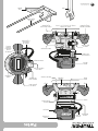
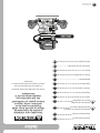
Parts
Speed
Control
Height Fine
Adjusting Knob
Collet
Included 1/4” and 1/2”
Handle
Cylinder
Axis
Lock Anti-chip
Cover
Carbon
Brushes Cap
Power
Cord
Power
cord protector
Height Fine
Adjusting Knob
Height
Adjusting
Button
Height
Adjusting
Button
Handle
Power indicator
(connection to
power supply)
Parallel
Guide
Wrench
Additional Base to
Guard the Material
Locking lever
Orifices to Insert
the Parallel Guide
Vacuuming
Port
Dust extraction
connector
Parallel Guide
Blocking Levers
Parallel Guide
Blocking Levers
Locking lever
Switch
Height
Adjusting
Button
Fixed
Base
Speed
Control
Parallel
Guide Rods
6ENGLISH

7
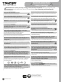
Preparation
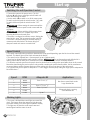
• Before setting or removing
a bit switch off and disconnect the router from
the power source.
• Remove the cylinder (A) from the fixed base as
indicated in the previous paragraph and set the motor
head on a flat surface having the cylinder pointing
upwards.
• Press the axis lock ( I ) to prevent it from rotating.
• With the lock depressed and without releasing use the
wrench included to loosen the chuck nut (J).
• Set the bit (K) into the chuck, the shank must be inside at
least 5/8” to assure the bit will not accidentally fall.
• Firmly tighten the chuck nut using the included wrench to
fasten the bit.
• Release the axis lock ( I ) and double-check the bit is
properly fixed.
• When using the additional base (page 8)
do not use bits with diameters higher than 1 1/4”.
Otherwise the base will get ruined.
• To remove the bit press the axis lock and loosen the
chuck using the included wrench.
Bit Set Up
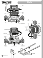
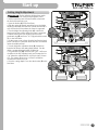
• The router motor is housed in the vertical cylinder (A)
going up and down inside the fixed base (B) to adjust the
bit to the height that is the right one to the job to do.
• Before fixing the bit or removing the
chuck, the cylinder shall be removed from the fixed base.
• Before disassembling and assembling
the cylinder switch off and disconnect the router from the
power source.
• To remove the cylinder release the lever (C) from the
fixed base bracket.
• Keep the height-adjusting button pressed (D).
• Lift the motor head (E) until removing the cylinder from
the fixed base.
• To assemble back the cylinder double-check the cylinder
slot (F) is aligned with the guide in the base.
• Press the height-adjusting button (D) while setting the
cylinder in the fixed base. Release the button so that the
lock (G) fits in one of the stops (H), depending of the
height of the selected bit to make the job.
• Push the lever (C) to close the bracket.
Cylinder Assembly and Disassembly
• Remove the bit as explained in the previous paragraph.
• Press the axis lock ( I ) to prevent it from rotating.
• Without releasing the axis lock remove the chuck (J)
from the threaded axis (L). Use the wrench turning the
nut counterclockwise.
• Set the chuck with the required diameter into the
threaded axis. Turn the nut clockwise.
Chuck Replacement
G
G
I
DC
H
A
A
E
F
J
K
H
B
L
ENGLISH
CAUTION
CAUTION
CAUTION
CAUTION

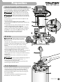
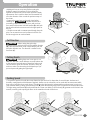
• Assemble the rods (B) against the parallel guide (A)
as described below:
• Slide the rip fence rods (B) into the holes (C) n the
router base to the depth required for the job and
tighten the locking levers (D).
• To connect the vacuum cleaner to the suction port located
at the back of the fixed base, first install the dust extraction
port (included); the included suction adapter has the right
size to accept a 1 1/4" (G) vacuum hose compatible with
Truper vacuum hoses (ASPI-5X, ASPI-06, ASPI-04, ASPI-03
and ASPI-5S).
• To connect the suction adapter to the suction port, align
the two tabs located on the extraction port (E) with the two
slots located on the suction port (F) and secure the adapter
by turning it clockwise.
• Always wear eye protection. The spark guard is not designed as a
safety guard. To remove the spark guard from the fixed base, press in on the tabs
until the spark guard is released from the base and then remove it. To secure the
spark guard, place it back in position and flex the sides while pushing it in until it
locks back into place.
• The chip deflector helps keep dust and chips away from the
operator; it will not stop larger objects than wood chips thrown by the drill bit.
• Always have the appropriate chip deflector against chips in place
on the base when operating the router.
Parallel guide
Chip deflector
Dust extraction port
C
B
E
G
F
D
A
8
Preparation
ENGLISH
CAUTION
CAUTION
CAUTION

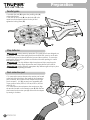
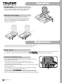
• Before adjusting height please switch
off and disconnect the router from the power source.
• Set the router base onto a flat and leveled surface with
the back of the tool facing you.
• Open the bracket (E) in the fixed base.
• With the cutting bit already assembled, press de height
adjusting button (F) and lower the cylinder until the bit is
very close to the surface where the router is supported.
• Turn the height fine adjusting knob (G) until the bit
barely touches the surface where the router is supported.
• Without moving the fine adjusting knob turn the
graduated ring (H) until zero “0” is aligned with the mark
( I ) in the fixed base.
• Set the router on top of two discarded and leveled work
pieces. Set them in a way that allows the bit to be lowered
under the additional base.
• Turn the height fine adjustment knob (G) clockwise to
lower the bit down to the cutting depth desired. Turn the
dial in a counterclockwise direction to lift the bit.
• The graduated ring (H) increases each 1/64”. Half a turn
clockwise of the fine adjusting knob (180°) lowers the bit
1/16” below the additional base. A full turn (360°) lowers
1/8”. The system allows up to 7 full 360° revolutions
clockwise to lower the bit 7/8”.
• Once the cutting depth is set, close the bracket (E) in the
fixed base.
Cutting Height Adjustment
9
Start up
E
F
G
H
I
ENGLISH
CAUTION
E
F
G
H

ON OFF
A
B
C
Start up
10 ENGLISH
• Connect the router to the power source. The ON
indicator (A) will show a green light and will switch off
when disconnecting the router.
• Use the switch (B) to switch on or off the router motor.
To switch on the tool push the switch into the “ON” mark.
To switch off the tool push the switch into the “OFF”
mark.
• When starting the motor wait until the
bit gets to the maximum speed to make contact with the
work piece.
• When switching off the motor please
wait for the bit to come to a complete stop before
removing the bit from the work piece.
• The motor is configured to minimize torque, limiting the
speed while it starts. This increases the motor useful life.
• The motor is built with electronic feedback keeping a
constant speed while loaded. This feature brings an
adequate control and assures a smooth finish.
Switching On and Operation Control
• The speed control (C) makes possible to determine the router speed depending upon the bit size and the material
hardness. This feature gives a finer finish and extends the bits life.
• The control can be adjusted from 1 (lowest speed) up to 6 (highest speed).
• Speed can be adjusted with the motor running, however do not change the speed while the bit is
making contact with the work piece. Otherwise, the control on the machine is lost due to sudden vibration.
• To select the required speed turn the speed control to desired level according to the speed table shown in this manual.
Remember, determining the precise speed is only possible consulting the speed reference tables, the bit manufacturer
recommendations and the operator experience when making trial cuts on scrap pieces of the same wood.
• As a general rule, the low speed is adequate for 1” bits or bigger and heavy-duty cutting bits. High speed is adequate for
bits smaller than 1”.
Speed Control
Speed RPM Adequate Bit Applications
• The router is built with three work lights set around the
chuck. This feature allows the operator to light the work
piece while making a cut and to get an optimum visibility.
• The lights are on when the router motor starts and
remain lighted until the motor is set off.
Working Lights
CAUTION
CAUTION
CAUTION
1
2
3
4
5
6
10000
13000
16000
19000
22000
25000
From 3” to 3 1/2”Non-ferrous metal, hard woods.
Large diameter bits.
Soft woods, plastic, covering.
Small diameter bits.
From 2 1/4” to 2 1/2”
From 1 1/4” to 2”
Up to 1”

• Making trial cuts on scrap wood before cutting the
definitive material is important. Trial cuts allow the
operator to rehearse the cut and make speed and depth
adjustments. Also is useful to learn how the material will
react, the direction of the cut and the optimum setup of
the router.
• Support the router base on the work piece before
switching on. Double-check the bit is
not making contact with the work piece until you have
firm control of the router. Hold the handles (A) with both
hands and wait for the motor to reach the right speed for
the job.
• Guide the router with a constant speed through the work
piece. Do not exercise too much pressure in the bit. Give
the bit enough time to cut the material.
A
B
D E F
C
Operation
11
ENGLISH
• When cutting along the edge,
double-check you guide the bit in the bit rotation direction
(B). Otherwise the router could unexpectedly fly out and
will make defective cuts. The direction is marked in the
fixed base (C).
Cut Direction
• Making deep cuts in one pass is not
advisable. Bits with a small diameter are easily broken due
to the excessive load and torque. Bigger bits make rough
cuts and hard to guide and control. To make a deep cut
make successive cuts increasing the bit depth up to 1/8”
per each pass until getting the right depth.
Cutting Depth
CAUTION
CAUTION
CAUTION
• The speed to push the bit with the router determines the finish and is dependent of several factors: hardness and
humidity, cutting depth and bit diameter. Regularly, shallow cuts in soft woods can be made with fast movements while
deep cuts in hard woods are made slower. To determine the ideal speed is indispensable to make test cuts in a piece of
scrap material. Making cutting movements too fast (D) make the bit biting large pieces of material and overheat the motor.
The right cutting movements (E) make small bites and clean cuts. Making cuts too slowly (F) generate much friction in the
material, scratching and exposing the fibers in the material and make charred cuts.
Pushing Speed

Carbon
Brushes Cap
• Double-check the machine ventilation slots are free of sawdust, chips, etc.
• Keep the guides clean and lubricated using multi-purpose light oil.
• The tool repair service shall always be carried out in a Authorized Service Center. If the repair service in
the machine are carried out personnel not authorized by , the Warranty will be made void.
• Bits built with an incorporated stopper are ideal for
edges. The work piece by itself can serve as a guide when
its thickness is higher than the bit height (H). If the work
piece has a smaller thickness than the bit height use a
guide (I) to make the cut.
Carbon Brush Replacement
Repair Service
H
G
I
• It is necessary to replace worn (burnt, broken or smaller then 0.19” long),
carbon brushes with new ones.
• When replacing carbon brushes always replace both carbons.
• Remove the worn carbon brushes from their housing. Remove the
accumulated dust with compressed air.
• Set the new carbon brushes reversing the order. The carbon brushes shall fall
easily into the housing.
• After setting the new carbons make the router run unloaded a couple of
minutes to let the carbon brushes have a better fit.
• Use only original spare carbon brushes specifically
designed with the hardness and electric resistance adequate for each type of
motor. The carbon brushes that are out of specification may damage the motor.
12
Operation
Maintenance
ENGLISH
Parallel Guide
Bits with Guide Stopper
• Fix the parallel guide (G) in the router base (page 8) and
support it in the work piece edge to make straight cuts.

13
Troubleshooting
ENGLISH
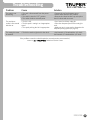
Problem Cause Solution
• Connect the cord to the power source.
• Set the switch into the “ON” position.
• Remove the carbon brushes cap and replace
the old carbons with new ones.
• Set a honed and sharp cutting bit.
• Select the adequate speed for the cutting bit
used.
• Make test cuts in scrap wood to determine the
adequate pushing speed (see page 10).
• Use bits with 1/4” shank with the 1/4” chuck.
Use bits with 1/2” shank with the 1/2” chuck.
The router is not
functioning.
The work piece
surface is not smooth
after the cut.
The cutting bit cannot
be installed.
• The cord is disconnected from the power
source.
• The switch is into the “OFF” position.
• The carbon brushes are totally worn.
• The bit is dull.
• The bit speed is cutting in an inappropriate
speed.
• The speed pushing the bit is inappropriate.
• The bit has not the right size for the chuck.
If the problems cannot be solved despite the corrective actions recommended,
contact a Authorized Service Center

14 ENGLISH
Notes

15
Authorized Service Centers
ENGLISH
In the event of any problem contacting a Truper Authorized Service Center, please see our webpage www.truper.com
to get an updated list, or call our toll-free numbers 800 690-6990 or 800-018-7873 to get information about the
nearest Service Center.
AGUASCALIENTES
BAJA
CALIFORNIA
BAJA
CALIFORNIA SUR
CAMPECHE
CHIAPAS
CHIHUAHUA
CIUDAD DE
MÉXICO
COAHUILA
COLIMA
DURANGO
ESTADO DE
MÉXICO
GUANAJUATO
GUERRERO
HIDALGO
JALISCO
MICHOACÁN
MORELOS
NAYARIT
NUEVO LEÓN
OAXACA
PUEBLA
QUERÉTARO
QUINTANA ROO
SAN LUIS
POTOSÍ
SINALOA
SONORA
TABASCO
TAMAULIPAS
TLAXCALA
VERACRUZ
YUCATÁN
DE TODO PARA LA CONSTRUCCIÓN
GRAL. BARRAGÁN #1201, COL. GREMIAL, C.P. 20030,
AGUASCALIENTES, AGS. TEL.: 449 994 0537
SUCURSAL TIJUANA
AV. LA ENCANTADA, LOTE #5, PARQUE INDUSTRIAL EL
FLORIDO II, C.P 22244, TIJUANA, B.C.
TEL.: 664 969 5100
FIX FERRETERÍAS
FELIPE ÁNGELES ESQ. RUIZ CORTÍNEZ S/N, COL. PUEBLO
NUEVO, C.P. 23670, CD. CONSTITUCIÓN, B.C.S.
TEL.: 613 132 1115
TORNILLERÍA Y FERRETERÍA AAA
AV. ÁLVARO OBREGÓN #324, COL. ESPERANZA
C.P. 24080 CAMPECHE, CAMP. TEL.: 981 815 2808
FIX FERRETERÍAS
AV. CENTRAL SUR #27, COL. CENTRO, C.P. 30700,
TAPACHULA, CHIS. TEL.: 962 118 4083
SUCURSAL CHIHUAHUA
AV. SILVESTRE TERRAZAS #128-11, PARQUE INDUSTRIAL
BAFAR, CARRETERA MÉXICO CUAUHTÉMOC, C.P. 31415,
CHIHUAHUA, CHIH. TEL. 614 434 0052
FIX FERRETERÍAS
EL MONSTRUO DE CORREGIDORA, CORREGIDORA # 35,
COL. CENTRO, C.P. 06060, CUAUHTÉMOC, CDMX.
TEL: 55 5522 5031 / 5522 4861
SUCURSAL TORREÓN
CALLE METAL MECÁNICA #280, PARQUE INDUSTRIAL
ORIENTE, C.P. 27278, TORREÓN, COAH.
TEL.: 871 209 68 23
BOMBAS Y MOTORES BYMTESA DE MANZANILLO
BLVD. MIGUEL DE LA MADRID #190, COL. 16 DE
SEPTIEMBRE, C.P. 28239, MANZANILLO, COL.
TEL.: 314 332 1986 / 332 8013
TORNILLOS ÁGUILA, S.A. DE C.V.
MAZURIO #200, COL. LUIS ECHEVERRÍA, DURANGO,
DGO.TEL.: 618 817 1946 / 618 818 2844
SUCURSAL CENTRO JILOTEPEC
PARQUE INDUSTRIAL # 1, COL. PARQUE INDUSTRIAL
JILOTEPEC, JILOTEPEC, EDO. DE MÉX. C.P. 54257
TEL: 761 782 9101 EXT. 5728 Y 5102
CÍA. FERRETERA NUEVO MUNDO S.A. DE C.V.
AV. MÉXICO - JAPÓN #225, CD. INDUSTRIAL, C.P. 38010,
CELAYA, GTO. TEL.: 461 617 7578 / 79 / 80 / 88
CENTRO DE SERVICIO ECLIPSE
CALLE PRINCIPAL MZ.1 LT. 1, COL. SANTA FE, C.P. 39010,
CHILPANCINGO, GRO. TEL.: 747 478 5793
FERREPRECIOS S.A. DE C.V.
LIBERTAD ORIENTE #304 LOCAL 30, INTERIOR DE PASAJE
ROBLEDO, COL. CENTRO, C.P. 43600, TULANCINGO,
HGO. TEL.: 775 753 6615 / 775 753 6616
SUCURSAL GUADALAJARA
AV. ADOLFO B. HORN # 6800, COL: SANTA CRUZ DEL
VALLE, C.P.: 45655, TLAJOMULCO DE ZUÑIGA, JAL.
TEL.: 33 3606 5285 AL 90
FIX FERRETERÍAS
AV. PASEO DE LA REPÚBLICA #3140-A, COL.
EX-HACIENDA DE LA HUERTA, C.P. 58050, MORELIA,
MICH. TEL.: 443 334 6858
FIX FERRETERÍAS
CAPITÁN ANZURES #95, ESQ. JOSÉ PERDIZ, COL.
CENTRO, C.P. 62740, CUAUTLA, MOR.
TEL.: 735 352 8931
HERRAMIENTAS DE TEPIC
MAZATLAN #117, COL. CENTRO, C.P. 63000, TEPIC, NAY.
TEL.: 311 258 0540
SUCURSAL MONTERREY
CARRETERA LAREDO #300, 1B MONTERREY PARKS,
COLONIA PUERTA DE ANÁHUAC, C.P. 66052, ESCOBEDO,
NUEVO LEÓN, TEL.: 81 8352 8791 / 81 8352 8790
FIX FERRETERÍAS
AV. 20 DE NOVIEMBRE #910, COL. CENTRO, C.P. 68300,
TUXTEPEC, OAX. TEL.: 287 106 3092
SUCURSAL PUEBLA
AV PERIFÉRICO #2-A, SAN LORENZO ALMECATLA,
C.P. 72710, CUAUTLACINGO, PUE.
TEL.: 222 282 8282 / 84 / 85 / 86
ARU HERRAMIENTAS S.A DE C.V.
AV. PUERTO DE VERACRUZ #110, COL. RANCHO DE
ENMEDIO, C.P. 76842, SAN JUAN DEL RÍO, QRO.
TEL.: 427 268 4544
FIX FERRETERÍAS
CARRETERA FEDERAL MZ. 46 LT. 3 LOCAL 2, COL EJIDAL,
C.P. 77710 PLAYA DEL CARMEN, Q.R.
TEL.: 984 267 3140
FIX FERRETERÍAS
AV. UNIVERSIDAD #1850, COL. EL PASEO, C.P. 78320,
SAN LUIS POTOSÍ, S.L.P. TEL.: 444 822 4341
SUCURSAL CULIACÁN
AV. JESÚS KUMATE SUR #4301, COL. HACIENDA DE LA
MORA, C.P. 80143, CULIACÁN, SIN.
TEL.: 667 173 9139 / 173 8400
FIX FERRETERÍAS
CALLE 5 DE FEBRERO #517, SUR LT. 25 MZ. 10, COL.
CENTRO, C.P. 85000, CD. OBREGÓN, SON.
TEL.: 644 413 2392
SUCURSAL VILLAHERMOSA
CALLE HELIO LOTES 1, 2 Y 3 MZ. #1, COL. INDUSTRIAL,
2A ETAPA, C.P. 86010, VILLAHERMOSA, TAB.
TEL.: 993 353 7244
VM ORINGS Y REFACCIONES
CALLE ROSITA #527 ENTRE 20 DE NOVIEMBRE Y GRAL.
RODRÍGUEZ, FRACC. REYNOSA, C.P. 88780, REYNOSA,
TAMS. TEL.: 899 926 7552
SERVICIOS Y HERRAMIENTAS INDUSTRIALES
PABLO SIDAR #132, COL . BARRIO DE SAN BARTOLOMÉ,
C.P. 90970, SAN PABLO DEL MONTE, TLAX.
TEL.: 222 271 7502
LA CASA DISTRIBUIDORA TRUPER
BLVD. PRIMAVERA. ESQ. HORTENSIA S/N, COL.
PRIMAVERA C.P. 93308, POZA RICA, VER.
TEL.: 782 823 8100 / 826 8484
SUCURSAL MÉRIDA
CALLE 33 #600 Y 602, LOCALIDAD ITZINCAB Y MULSAY,
MPIO. UMÁN, C.P. 97390, MÉRIDA, YUC.
TEL.: 999 912 2451

Warranty. Duration: 5 year. Coverage: parts, components and workmanship against manufacturing or operating
defects, except if used under conditions other than normal; when it was not operated in accordance with the
instructive; was altered or repaired by personnel not authorized by Truper®. To make the warranty valid, only
present the product in the establishment where you bought it or in Corregidora 35, Centro, Cuauhtémoc, CDMX,
06060, where you can also purchase parts, components, consumables and accessories. The costs of
transportation of the product that derive from its fulfillment of its service network are included. Truper will not
require any proof of purchase to make the warranty effective. Phone number 800-018-7873. Made in China.
Imported by Truper, S.A. de C.V. Parque Industrial 1, Parque Industrial Jilotepec, Jilotepec, Edo. de Méx.
C.P. 54257, Phone number 761 782 9100.
16 ENGLISH www.truper.com
01-2023
16686
Warranty
policy
Stamp of the business. Delivery date:
Code
ROU-NX3
Model Brand

Garantía. Duración: 5 años. Cobertura: piezas, componentes y mano de obra contra defectos de fabricación o
funcionamiento, excepto si se usó en condiciones distintas a las normales; cuando no fue operado conforme
instructivo; fue alterado o reparado por personal no autorizado por Truper®. Para hacer efectiva la garantía
únicamente presente el producto en el establecimiento donde lo compró o en Corregidora 35, Centro,
Cuauhtémoc, CDMX, 06060, donde también podrá adquirir partes, componentes, consumibles y accesorios.
Incluye los gastos de transportación del producto que deriven de su cumplimiento de su red de servicio. Truper
no solicitará ningún tipo de comprobante de pago para hacer efectiva la garantía. Tel. 800-018-7873. Made
in/Hecho en China. Importador Truper, S.A. de C.V. Parque Industrial 1, Parque Industrial Jilotepec, Jilotepec, Edo.
de Méx. C.P. 54257, Tel. 761 782 9100.
16 ESPAÑOL
Póliza de
Garantía
www.truper.com
01-2023
Sello del establecimiento comercial. Fecha de entrega:
ROU-NX3
Modelo
16686
Código Marca

15
Centros de Servicio Autorizados
ESPAÑOL
En caso de tener algún problema para contactar un Centro de Servicio Autorizado Truper
®
consulte nuestra página
www.truper.com donde obtendrá un listado actualizado, o llame al: 800 690 6990 u 800-018-7873 donde le
informarán cuál es el Centro de Servicio más cercano.
AGUASCALIENTES
BAJA
CALIFORNIA
BAJA
CALIFORNIA SUR
CAMPECHE
CHIAPAS
CHIHUAHUA
CIUDAD DE
MÉXICO
COAHUILA
COLIMA
DURANGO
ESTADO DE
MÉXICO
GUANAJUATO
GUERRERO
HIDALGO
JALISCO
MICHOACÁN
MORELOS
NAYARIT
NUEVO LEÓN
OAXACA
PUEBLA
QUERÉTARO
QUINTANA ROO
SAN LUIS
POTOSÍ
SINALOA
SONORA
TABASCO
TAMAULIPAS
TLAXCALA
VERACRUZ
YUCATÁN
DE TODO PARA LA CONSTRUCCIÓN
GRAL. BARRAGÁN #1201, COL. GREMIAL, C.P. 20030,
AGUASCALIENTES, AGS. TEL.: 449 994 0537
SUCURSAL TIJUANA
AV. LA ENCANTADA, LOTE #5, PARQUE INDUSTRIAL EL
FLORIDO II, C.P 22244, TIJUANA, B.C.
TEL.: 664 969 5100
FIX FERRETERÍAS
FELIPE ÁNGELES ESQ. RUIZ CORTÍNEZ S/N, COL. PUEBLO
NUEVO, C.P. 23670, CD. CONSTITUCIÓN, B.C.S.
TEL.: 613 132 1115
TORNILLERÍA Y FERRETERÍA AAA
AV. ÁLVARO OBREGÓN #324, COL. ESPERANZA
C.P. 24080 CAMPECHE, CAMP. TEL.: 981 815 2808
FIX FERRETERÍAS
AV. CENTRAL SUR #27, COL. CENTRO, C.P. 30700,
TAPACHULA, CHIS. TEL.: 962 118 4083
SUCURSAL CHIHUAHUA
AV. SILVESTRE TERRAZAS #128-11, PARQUE INDUSTRIAL
BAFAR, CARRETERA MÉXICO CUAUHTÉMOC, C.P. 31415,
CHIHUAHUA, CHIH. TEL. 614 434 0052
FIX FERRETERÍAS
EL MONSTRUO DE CORREGIDORA, CORREGIDORA # 35,
COL. CENTRO, C.P. 06060, CUAUHTÉMOC, CDMX.
TEL: 55 5522 5031 / 5522 4861
SUCURSAL TORREÓN
CALLE METAL MECÁNICA #280, PARQUE INDUSTRIAL
ORIENTE, C.P. 27278, TORREÓN, COAH.
TEL.: 871 209 68 23
BOMBAS Y MOTORES BYMTESA DE MANZANILLO
BLVD. MIGUEL DE LA MADRID #190, COL. 16 DE
SEPTIEMBRE, C.P. 28239, MANZANILLO, COL.
TEL.: 314 332 1986 / 332 8013
TORNILLOS ÁGUILA, S.A. DE C.V.
MAZURIO #200, COL. LUIS ECHEVERRÍA, DURANGO,
DGO.TEL.: 618 817 1946 / 618 818 2844
SUCURSAL CENTRO JILOTEPEC
PARQUE INDUSTRIAL # 1, COL. PARQUE INDUSTRIAL
JILOTEPEC, JILOTEPEC, EDO. DE MÉX. C.P. 54257
TEL: 761 782 9101 EXT. 5728 Y 5102
CÍA. FERRETERA NUEVO MUNDO S.A. DE C.V.
AV. MÉXICO - JAPÓN #225, CD. INDUSTRIAL, C.P. 38010,
CELAYA, GTO. TEL.: 461 617 7578 / 79 / 80 / 88
CENTRO DE SERVICIO ECLIPSE
CALLE PRINCIPAL MZ.1 LT. 1, COL. SANTA FE, C.P. 39010,
CHILPANCINGO, GRO. TEL.: 747 478 5793
FERREPRECIOS S.A. DE C.V.
LIBERTAD ORIENTE #304 LOCAL 30, INTERIOR DE PASAJE
ROBLEDO, COL. CENTRO, C.P. 43600, TULANCINGO,
HGO. TEL.: 775 753 6615 / 775 753 6616
SUCURSAL GUADALAJARA
AV. ADOLFO B. HORN # 6800, COL: SANTA CRUZ DEL
VALLE, C.P.: 45655, TLAJOMULCO DE ZUÑIGA, JAL.
TEL.: 33 3606 5285 AL 90
FIX FERRETERÍAS
AV. PASEO DE LA REPÚBLICA #3140-A, COL.
EX-HACIENDA DE LA HUERTA, C.P. 58050, MORELIA,
MICH. TEL.: 443 334 6858
FIX FERRETERÍAS
CAPITÁN ANZURES #95, ESQ. JOSÉ PERDIZ, COL.
CENTRO, C.P. 62740, CUAUTLA, MOR.
TEL.: 735 352 8931
HERRAMIENTAS DE TEPIC
MAZATLAN #117, COL. CENTRO, C.P. 63000, TEPIC, NAY.
TEL.: 311 258 0540
SUCURSAL MONTERREY
CARRETERA LAREDO #300, 1B MONTERREY PARKS,
COLONIA PUERTA DE ANÁHUAC, C.P. 66052, ESCOBEDO,
NUEVO LEÓN, TEL.: 81 8352 8791 / 81 8352 8790
FIX FERRETERÍAS
AV. 20 DE NOVIEMBRE #910, COL. CENTRO, C.P. 68300,
TUXTEPEC, OAX. TEL.: 287 106 3092
SUCURSAL PUEBLA
AV PERIFÉRICO #2-A, SAN LORENZO ALMECATLA,
C.P. 72710, CUAUTLACINGO, PUE.
TEL.: 222 282 8282 / 84 / 85 / 86
ARU HERRAMIENTAS S.A DE C.V.
AV. PUERTO DE VERACRUZ #110, COL. RANCHO DE
ENMEDIO, C.P. 76842, SAN JUAN DEL RÍO, QRO.
TEL.: 427 268 4544
FIX FERRETERÍAS
CARRETERA FEDERAL MZ. 46 LT. 3 LOCAL 2, COL EJIDAL,
C.P. 77710 PLAYA DEL CARMEN, Q.R.
TEL.: 984 267 3140
FIX FERRETERÍAS
AV. UNIVERSIDAD #1850, COL. EL PASEO, C.P. 78320,
SAN LUIS POTOSÍ, S.L.P. TEL.: 444 822 4341
SUCURSAL CULIACÁN
AV. JESÚS KUMATE SUR #4301, COL. HACIENDA DE LA
MORA, C.P. 80143, CULIACÁN, SIN.
TEL.: 667 173 9139 / 173 8400
FIX FERRETERÍAS
CALLE 5 DE FEBRERO #517, SUR LT. 25 MZ. 10, COL.
CENTRO, C.P. 85000, CD. OBREGÓN, SON.
TEL.: 644 413 2392
SUCURSAL VILLAHERMOSA
CALLE HELIO LOTES 1, 2 Y 3 MZ. #1, COL. INDUSTRIAL,
2A ETAPA, C.P. 86010, VILLAHERMOSA, TAB.
TEL.: 993 353 7244
VM ORINGS Y REFACCIONES
CALLE ROSITA #527 ENTRE 20 DE NOVIEMBRE Y GRAL.
RODRÍGUEZ, FRACC. REYNOSA, C.P. 88780, REYNOSA,
TAMS. TEL.: 899 926 7552
SERVICIOS Y HERRAMIENTAS INDUSTRIALES
PABLO SIDAR #132, COL . BARRIO DE SAN BARTOLOMÉ,
C.P. 90970, SAN PABLO DEL MONTE, TLAX.
TEL.: 222 271 7502
LA CASA DISTRIBUIDORA TRUPER
BLVD. PRIMAVERA. ESQ. HORTENSIA S/N, COL.
PRIMAVERA C.P. 93308, POZA RICA, VER.
TEL.: 782 823 8100 / 826 8484
SUCURSAL MÉRIDA
CALLE 33 #600 Y 602, LOCALIDAD ITZINCAB Y MULSAY,
MPIO. UMÁN, C.P. 97390, MÉRIDA, YUC.
TEL.: 999 912 2451

14 ESPAÑOL
Notas

13
Solución de problemas
ESPAÑOL
Problema Causa Solución
Si los problemas persisten a pesar de realizar las acciones correctivas recomendadas,
contacte a un Centro de Servicio Autorizado .
• Conecte el cable al suministro eléctrico.
• Coloque el interruptor en la posición “ON”.
• Retire las tapas de los carbones y cambie los
carbones viejos por carbones nuevos.
• Coloque una broca de corte con filo.
• Seleccione una velocidad adecuada para la
broca de corte que sea la adecuada.
• Realice cortes de prueba en material de
desecho para determinar la velocidad de
empuje adecuada (consulte la página 10).
• Utilice brocas con zanco de 1/4” (6.5 mm) con
el collarín de 1/4” (6.5 mm); utilice brocas con
zanco de 1/2” (13 mm) con el collarín de
1/2” (13 mm).
La rebajadora no
funciona.
La superficie de la
pieza de trabajo no
está lisa después de
cortar.
No se puede instalar la
broca de corte.
• Cable desconectado del suministro eléctrico.
• El interruptor está en la posición “OFF”.
• Los carbones están desgastados por
completo.
• La broca no tiene filo.
• La velocidad de la broca rebaja a una
velocidad inapropiada.
• La velocidad con que se empuja la broca es
inadecuada.
• La medida de la broca no es la correcta para
el collarín.

Tapa de carbones
• Asegúrese de que las ranuras de ventilación de la máquina se mantengan libres de aserrín / astillas, etc.
• Mantenga las guías limpias y lubricadas con un aceite ligero multiusos.
• El servicio de reparación de la herramienta siempre debe ser realizado por un Centro de Servicio Autorizado
. Si los servicios de reparación de la máquina son realizados por personal no autorizado por
, la garantía del producto se invalidará.
• Las brocas con topes incorporados son ideales para
trabajar bordes. La misma pieza de trabajo puede servir
de guía cuando su espesor es mayor a la altura de la
broca (H). Si la pieza de trabajo es de un espesor menor
a la altura de la broca use una guía (I) para realizar el
corte.
Cambio de carbones
Servicio de reparación
H
G
I
• Es necesario reemplazar los carbones desgastados (quemados, rotos o de
menos de 5 mm de largo), con carbones nuevos.
• Cuando se haga el cambio de carbones siempre deben cambiarse los dos
carbones.
• Retire los carbones desgastados del portacarbones y retire el polvo
acumulado con aire comprimido.
• Coloque los carbones nuevos invirtiendo el orden. Los carbones deben caer
en los portacarbones fácilmente.
• Después de colocar los carbones nuevos, permita que la rebajadora funcione
durante algunos minutos sin carga de trabajo para que los carbones tengan un
mejor ajuste.
• Sólo se deben de usar carbones de repuesto originales,
diseñados específicamente con la dureza y la resistencia eléctrica adecuada
para cada tipo de motor. Los carbones fuera de especificaciones pueden dañar
el motor.
12
Operación
Mantenimiento
ESPAÑOL
Guía paralela
Brocas con tope guía
• Instale la guía paralela (G) en la base de la rebajadora
(página 8), y apóyela en el canto de la pieza de trabajo
para hacer cortes rectos.

• Es importante realizar cortes de prueba en material de
desecho antes de realizar el corte en el material definitivo.
Los cortes de prueba permiten al operador ensayar el
corte para realizar ajustes de velocidad y profundidad, así
como para tener nociones de la respuesta del material, la
dirección de corte y el acomodo óptimo de la rebajadora.
• Apoye la base de la rebajadora en la pieza de trabajo
antes de encenderla. Asegúrese de que
la broca no esté en contacto con la pieza de trabajo hasta
que usted tenga el control de la rebajadora con ambas
manos sujetando firmemente los mangos (A) y que el
motor haya alcanzado la máxima velocidad determinada
para el trabajo.
• Guíe la rebajadora a velocidad constante a través de la
pieza de trabajo sin ejercer demasiada presión en la broca,
dando tiempo suficiente para que la broca corte el material.
A
B
D E F
C
Operación
11
ESPAÑOL
• Cuando corte a lo largo de un borde,
asegúrese de guiar la broca en el mismo sentido de la
dirección de rotación de la broca (B). De lo contrario la
rebajadora puede salir disparada inesperadamente y
además producir cortes defectuosos. La dirección está
marcada en la base fija (C).
Dirección de corte
• No es aconsejable hacer cortes
profundos de un solo corte. Las brocas de diámetro
pequeño se rompen con facilidad debido a la carga y
torque excesivos; mientras que las brocas más grandes
producen cortes burdos y son difíciles de guiar y
controlar. Para realizar un corte profundo hágalo con
cortes sucesivos incrementando la profundidad de la
broca hasta 1/8” (3 mm) por cada pasada hasta llegar a la
profundidad deseada.
Profundidad de corte
ATENCIÓN
ATENCIÓN
ATENCIÓN
• La velocidad con que se empuja la broca con la rebajadora determina el acabado del corte y depende de varios factores:
dureza y humedad de la pieza de trabajo, profundidad de corte y diámetro de la broca. Por lo regular los cortes poco
profundos en maderas suaves pueden hacerse con movimientos rápidos, mientras que los cortes profundos en maderas
duras se hacen más despacio. Para determinar la velocidad ideal es indispensable realizar ensayos en material de desecho.
Los movimientos de corte demasiado rápidos (D) hacen que la broca saque bocados de material muy grande, además de
sobrecargar el motor. Los movimientos de corte adecuados (E) hacen que la broca saque bocados pequeños y cortes
limpios. Los movimientos de corte demasiado lentos (F) generan mucha fricción en el material, dando arañazos que dejan
expuestas las fibras del material y haciendo un corte chamuscado.
Velocidad de empuje

ON OFF
A
B
C
Puesta en marcha
10 ESPAÑOL
• Conecte la rebajadora a la fuente de alimentación. El
indicador de energía (A) se iluminará en verde y se
apagará cuando la rebajadora sea desconectada.
• Utilice el interruptor (B) para encender o apagar el
motor de la rebajadora. Para encender empuje el
interruptor hacia la marca “ON”, para apagar empuje el
interruptor hacia la marca “OFF”.
• Cuando encienda el motor espere a
que la broca alcance su máxima velocidad para hacer
contacto con la pieza de trabajo.
• Cuando apague el motor espere a
que la broca se detenga por completo antes de retirar la
broca de la pieza de trabajo.
• El motor está configurado para minimizar la torsión
limitando su velocidad durante el arranque, lo que
aumenta su vida útil.
• El motor cuenta con un control de retroalimentación
electrónica que mantiene la velocidad constante bajo
carga para brindar un control adecuado y asegurar un
acabado suave.
Encendido y control de operación
• Con el control de velocidad (C) es posible determinar la velocidad de la rebajadora dependiendo de la medida de la
broca y la dureza del material. Así se logra un acabado más fino y se extiende la vida útil de las brocas.
• El control puede ser ajustado de 1 (velocidad más baja) a 6 (velocidad más alta).
• La velocidad puede ser ajustada con el motor en marcha, sin embargo, no cambie la velocidad
cuando la broca esté en contacto con la pieza de trabajo, de lo contrario puede producirse una pérdida de control por la
vibración repentina.
• Para seleccionar la velocidad requerida gire el control de velocidad hasta el nivel deseado de acuerdo a la tabla de
velocidades mostrada en este instructivo. Recuerde que determinar la velocidad con exactitud sólo es posible consultado
las tablas de referencia de velocidad, las recomendaciones del fabricante de las brocas y la experiencia del operador al
realizar pruebas de corte en material de desecho.
• Como regla general las velocidades bajas son adecuadas para brocas de 1” (25 mm) o más grandes y brocas de corte
de uso rudo. Las velocidades altas son adecuadas para brocas de menos de 1” (25 mm).
Control de velocidad
Velocidad r/min broca apropiada Aplicaciones
• La rebajadora tiene tres luces de trabajo localizadas
alrededor de la tuerca con mordaza para iluminar la pieza de
trabajo mientras realiza el corte y tener una visibilidad óptima.
• Las luces se encienden cuando el motor de la rebajadora
arranca, y se mantienen así hasta que el motor es apagado.
Luces de trabajo
ATENCIÓN
ATENCIÓN
ATENCIÓN
1
2
3
4
5
6
10000
13000
16000
19000
22000
25000
de 3” a 3 1/2”
(de 75 mm a 90 mm) Metal no ferroso, maderas duras.
Brocas de diámetro grande.
Maderas suaves, plástico, cubiertas,
Brocas de diámetro pequeño.
de 2 1/4” a 2 1/2” (de 57 mm a 65 mm)
de 1 1/4” a 2”
(de 32 mm a 50 mm)
1" (25 mm) o menor

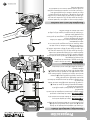
• Antes de ajustar la altura apague y
desconecte la rebajadora de la fuente de alimentación.
• Apoye la base de la rebajadora en una superficie plana y
nivelada con la parte trasera de la rebajadora frente a usted.
• Abra la abrazadera (E) de la base fija.
• Con la broca de corte ya instalada, presione el botón de
ajuste de altura (F) y baje el cilindro hasta que la broca
esté muy cerca a la superficie en la que está apoyada la
rebajadora.
• Gire la perilla de ajuste fino de altura (G) hasta que la
broca apenas toque la superficie en la que está apoyada
la rebajadora.
• Sin mover la perilla de ajuste fino gire el anillo
graduado (H) hasta que el cero “0” quede alineado con
la marca ( I ) de la base fija.
• Coloque la rebajadora sobre dos piezas de trabajo de
desecho que estén niveladas y colóquela de tal forma que
se pueda bajar la broca por debajo de la base
complementaria.
• Gire la perilla de ajuste fino de altura (G) en dirección a las
manecillas del reloj para bajar la broca hasta la profundidad
de corte que desee. Gire el selector en dirección contraria a
las manecillas del reloj para subir la broca.
• El anillo graduado (H) tiene incrementos de 1/64”
(0.5 mm). Media vuelta en dirección a las manecillas del
reloj (180°) de la perilla de ajuste fino baja la broca a
1/16”(1.5 mm) de profundidad por debajo de la base
complementaria, una vuelta completa (360°) la baja
1/8” (3 mm). El sistema permite hasta 7 revoluciones
completas de 360° en dirección a las manecillas del reloj,
para bajar la broca hasta 7/8" (22 mm).
• Una vez que determine la profundidad de corte, cierre la
abrazadera (E) de la base fija.
Ajuste de la altura de corte
9
Puesta en marcha
E
F
G
H
I
ESPAÑOL
ATENCIÓN
E
F
G
H

8
Preparación
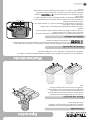
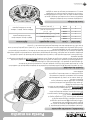
• Ensamble las varillas (B) contra la guía paralela (A)
como se observa en la imagen.
• Deslice las varillas (B) de la guía paralela en los
orificios (C) de la base de la rebajadora hasta la
profundidad requerida por el trabajo y apriete las
palancas (D) de bloqueo.
• Para conectar la aspiradora al orificio de aspiración
ubicado en la parte trasera de la base fija, instale primero
puerto para extracción de polvo (incluido); sobre el orificio
de aspiración. El adaptador de aspiración incluido tiene el
tamaño adecuado para aceptar una manguera de
aspiración de 1 1/4” (32 mm) (G) compatible con
mangueras de aspiradoras de la línea Truper (ASPI-5X,
ASPI-06, ASPI-04, ASPI-03 y ASPI-5S).
• Para conectar el adaptador de aspiración sobre el orificio
de aspiración, alinee las dos lengüetas ubicadas en el
puerto de extracción (E) con las dos ranuras ubicadas en el
orificio de aspiración (F) y fije el adaptador girándolo en el
sentido de las agujas del reloj.
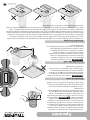
• Use siempre protección para los ojos. El escudo anti virutas
no está diseñado como protector de seguridad. Para retirar el deflector de viruta de la
base fija, presione hacia dentro en las lengüetas hasta que el deflector de viruta se
libere de la base y luego retírela. Para fijar el deflector de viruta vuelva a colocarla en
posición y flexione los lados mientras la empuja hacia dentro hasta que se trabe
nuevamente en su lugar.
• El deflector de viruta ayuda a mantener el polvo y las astillas
lejos del operador; no detendrá los objetos más grandes que las astillas de madera
que arroja la broca.
• Siempre tenga el deflector de viruta adecuada contra astillas
en su lugar en la base cuando opere la rebajadora.
Guía paralela
Deflector de viruta
Puerto para extracción de polvo
C
B
E
G
F
D
A
ESPAÑOL
ADVERTENCIA
ADVERTENCIA
ADVERTENCIA

7
Preparación
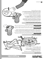
• Antes de colocar o retirar
una broca apague y desconecte la rebajadora
de la fuente de alimentación.
• Retire el cilindro (A) de la base fija como se indica en el
apartado anterior y apoye la cabeza del motor en una
superficie plana con el cilindro apuntando hacia arriba.
• Oprima el seguro del eje ( I ) para evitar que éste gire.
• Sin soltar el seguro del eje afloje la tuerca del collarín (J)
con la llave incluida.
• Coloque la broca (K) en el collarín, el zanco debe de
entrar al menos 16 mm para asegurar que la broca no se
salga accidentalmente.
• Apriete firmemente la tuerca del collarín con la llave
incluida para asegurar la broca.
• Suelte el seguro del eje ( I ) y asegúrese de que la broca
haya quedado bien colocada.
• Para retirar la broca oprima el seguro del eje y afloje la
tuerca del collarín con la llave incluida.
Instalación de la broca
• El motor de la rebajadora está alojado en el cilindro
vertical (A) que sube o baja dentro de la base fija (B)
para ajustar la broca a la altura adecuada para el trabajo a
realizar.
• Antes de instalar una broca o
cambiar el collarín, el cilindro debe de ser retirado de la
base fija.
• Antes de desmontar o montar el
cilindro apague y desconecte la rebajadora de la fuente de
alimentación.
• Para retirar el cilindro libere la palanca (C) de la
abrazadera de la base fija.
• Mantenga apretado el botón de ajuste de altura (D).
• Levante la cabeza del motor (E) hasta retirar el cilindro
de la base fija.
• Para montar el cilindro de nuevo asegúrese de alinear la
ranura del cilindro (F) con la guía de la base.
• Presione el botón de ajuste de altura (D) mientras
introduce el cilindro en la base fija. Suelte el botón para
que el seguro (G) calce en alguno de los tres topes (H),
dependiendo de la altura de la broca seleccionada para
realizar el trabajo.
• Empuje la palanca (C) para cerrar la abrazadera.
Desmontaje y montaje del cilindro
• Retire la broca como se explica en el apartado anterior.
• Oprima el seguro del eje ( I ) para evitar que éste gire.
• Sin soltar el seguro del eje retire la tuerca con mordaza
(J) del eje roscado (L), con ayuda de la llave girando la
tuerca en sentido contrario a las manecillas del reloj.
• Coloque la tuerca con mordaza del diámetro requerido
en el eje roscado girando la tuerca en el sentido de las
manecillas del reloj.
Reemplazo de tuerca con mordaza
G
G
I
DC
H
A
A
E
F
J
K
H
B
L
ESPAÑOL
ATENCIÓN
ATENCIÓN
ATENCIÓN

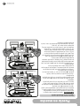
Partes
Control
de velocidad
Perilla de ajuste
fino de altura
Tuerca con mordaza
Incluye 1/4" (6.5 mm) y 1/2" (13 mm)
Mango
Cilindro
Seguro
del eje Cubierta
antiastillas
Tapa de
carbones
Cable de
alimentación
Perilla de ajuste
fino de altura
Botón de
ajuste de altura
Botón de
ajuste de altura
Mango
Indicador de
energía
(conexión al
suministro
electrico)
Guía
paralela
Llave
Protector de la base
Palanca de bloqueo
Orificios para insertar
la guía paralela
Puerto de
aspirado
Puerto para
extracción de polvo
Palancas de bloqueo
de la guía paralela
Palancas de
bloqueo de
la guía paralela
Palanca de bloqueo
Interruptor
Botón de
ajuste de altura
Base
fija
Control
de velocidad
Varillas de
la guía paralela
6ESPAÑOL
Protector
del cable

5
Advertencias de seguridad
para uso de rebajadoras
ESPAÑOL
• Aleje las manos del área de corte y de
la broca de corte. Al operar la herramienta sosténgala con
firmeza por ambos mangos con las dos manos para evitar
lesiones accidentales y prevenir la pérdida de control.
• El contacto accidental con una
broca de corte que esté girando puede ocasionar lesiones
personales de gravedad.
• NUNCA sostenga la pieza a cortar con
las manos o sobre una pierna. Sujete la pieza de trabajo
de manera adecuada para evitar el contacto del cuerpo
con la broca de corte, evitar que ésta se atore o perder el
control de la herramienta o la pieza de trabajo.
• No intente retirar material de desecho
cuando la broca de corte esté girando.
• Jamás ponga la mano por debajo
de la pieza de trabajo con la herramienta en marcha.
• Antes de cada uso revise que todas
las partes funcionen correctamente, si algo no funciona
dele servicio antes de operar la herramienta.
• Antes de transportar la herramienta
retire la broca de corte.
• Operar la herramienta sosteniéndola
por sus partes aisladas evita descargas al operario en caso
de que la broca haga contacto con cableado eléctrico oculto.
• Antes de dar mantenimiento,
retirar o instalar brocas, la guía paralela o el adaptador del
extractor de polvo, debe desconectar la herramienta del
suministro de energía.
• Mantenga SIEMPRE el cable de alimentación alejado del
área de corte. El cable de alimentación JAMÁS debe colgar
sobre la pieza de trabajo cuando haga el corte.
• Use siempre anteojos de seguridad con protección
lateral. En caso de producir polvo use también una
máscara para polvo.
El polvo originado al cortar ciertos materiales contienen
substancias químicas que se sabe causan daños a la
salud. Para reducir la exposición a estas substancias
químicas, trabaje en áreas bien ventiladas, y use el equipo
de seguridad adecuado, tal como mascarillas contra polvo
diseñadas específicamente para filtrar partículas
microscópicas.
Materiales tóxicos
• RIESGO DE CONTRAGOLPE.
Por contragolpe nos referimos al movimiento repentino y
con fuerza que sufre la herramienta hacia afuera de la
pieza de trabajo y que puede hacer perder el control al
operario o incluso provocarle una lesión. Por lo regular es
ocasionado cuando la broca de corte se atora en la pieza
o por una operación deficiente. Para evitarlo se deben
tomar las siguientes precauciones:
• Utilice brocas de corte en buen
estado y cerciórese que estén bien instaladas. Las brocas
mal instaladas, dañadas, sin filo o con desgaste tienden a
atorarse en el material provocando contragolpes.
• Al operar la rebajadora sosténgala
con firmeza con ambas manos por sus mangos laterales.
Mantenga su cuerpo bien equilibrado y en una posición
estable con ambos pies en el piso para resistir la fuerza
de un posible contragolpe.
• Para realizar un corte espere a que la
broca alcance su máxima velocidad antes de comenzar a
cortar. No encienda la herramienta con la broca apoyada
en la pieza de trabajo, podría provocar un contragolpe.
• Para reiniciar el trabajo dentro de un corte, centre la
broca en el corte y revise que los dientes no estén
enterrados en el material.
• Si se interrumpe el corte durante la
operación de la rebajadora, apague el interruptor y
sostenga la herramienta dentro de la pieza de trabajo
hasta que el motor se detenga por completo. No intente
retirar la broca mientras el motor siga en marcha, podría
provocar un contragolpe.
• Para minimizar el riesgo de que la
broca se atore y provoque un contragolpe, antes de cortar
una pieza de madera retire todos los clavos. La madera
húmeda, pandeada o tratada a presión requieren de
especial atención durante el corte. La goma y resina de la
madera que se endurece en las brocas de corte, hacen lenta
la rebajadora. Utilice removedor de goma y resina, agua
caliente o keroseno para retirar esas acumulaciones. NO use
gasolina.
• Antes de empezar cualquier corte,
las perillas de ajuste de profundidad de corte deben estar
apretadas y aseguradas. Si estas se mueven durante el
corte, pueden producir un contragolpe.
• Los cortes de profundidad excesiva
y/o el uso de brocas de diámetro grande aumentan la
carga en la unidad y la posibilidad de un contragolpe.
Haga varias pasadas con la rebajadora a profundidades
progresivas cuando el trabajo requiera retirar mucho
material o cuando use brocas de diámetro grande.
ATENCIÓN
ATENCIÓN
ADVERTENCIA
ADVERTENCIA
ADVERTENCIA
ADVERTENCIA
ADVERTENCIA
PELIGRO
PELIGRO
PELIGRO
ATENCIÓN
ATENCIÓN
ATENCIÓN
ATENCIÓN
ATENCIÓN
ATENCIÓN
ATENCIÓN

4
Área de trabajo
Mantenga el área de trabajo limpia y bien iluminada.
Las áreas desordenadas y obscuras son propensas a accidentes.
No maneje la herramienta en ambientes explosivos, como en
presencia de líquido, gas o polvo inflamables.
Las herramientas eléctricas producen chispas que pueden encender
material inflamable.
Mantenga alejados a los niños y curiosos cuando opere la
herramienta.
Las distracciones pueden hacer que pierda el control.
Seguridad eléctrica
La clavija de la herramienta debe coincidir con el tomacorrien-
te. Nunca modifique una clavija. No use ningún tipo de
adaptador para clavijas de herramientas puestas a tierra.
Clavijas modificadas y enchufes diferentes aumentan el riesgo de
choque eléctrico.
Evite el contacto del cuerpo con superficies puestas a tierra
como tuberías, radiadores, cocinas eléctricas y refrigeradores.
Hay un mayor riesgo de choque eléctrico si el cuerpo está puesto a tierra.
No exponga la herramienta a la lluvia o condiciones de humedad.
El agua que ingresa en la herramienta aumenta el riesgo de choque eléctrico.
No fuerce el cable. Nunca use el cable para transportar,
levantar o desconectar la herramienta. Mantenga el cable
lejos del calor, aceite, orillas afiladas o piezas en movimiento.
Los cables dañados o enredados aumentan el riesgo de choque eléctrico.
Cuando maneje una herramienta en exteriores, use una
extensión especial para uso en exteriores.
El uso de una extensión adecuada para exteriores reduce el riesgo de choque
eléctrico.
Si el uso de la herramienta en un lugar húmedo es inevitable,
use una alimentación protegida por un interruptor de circuito
de falla a tierra (GFCI).
El uso de un GFCI reduce el riesgo de choque eléctrico.
Seguridad personal
Esté alerta, vigile lo que está haciendo y use el sentido común
cuando maneje una herramienta. No la use si está cansado o
bajo la influencia de drogas, alcohol o medicamentos.
Un momento de distracción mientras maneja la herramienta puede
causar un daño personal.
Use equipo de seguridad. Use siempre protección para los ojos.
El uso de equipo de seguridad como lentes de seguridad, mascarilla antipolvo,
zapatos antideslizantes, casco y protección para los oídos en condiciones
apropiadas, reduce de manera significativa los daños personales.
Evite arranques accidentales. Asegúrese de que el interruptor
está en posición “apagado” antes de conectar a la fuente de
alimentación y/o a la batería o transportar la herramienta.
Transportar herramientas eléctricas con el dedo sobre el interruptor o
conectar herramientas eléctricas que tienen el interruptor en posición de
“encendido” puede causar accidentes.
Retire cualquier llave o herramienta de ajuste antes de arrancar
la herramienta eléctrica.
Las llaves o herramientas que quedan en las partes rotativas de la
herramienta pueden causar un daño personal.
No sobrepase su campo de acción. Mantenga ambos pies bien
asentados sobre el suelo y conserve el equilibrio en todo
momento.
Esto permite un mejor control de la herramienta en situaciones inesperadas.
Vista adecuadamente. No vista ropa suelta o joyas. Mantenga
su pelo, su ropa y guantes alejados de las piezas en
movimiento.
La ropa o el pelo suelto o las joyas pueden quedar atrapados en las piezas en
movimiento.
En caso de contar con dispositivos de extracción y recolección
de polvo conectados a la herramienta, verifique sus conexiones
y úselos correctamente.
El uso de estos dispositivos reduce los riesgos relacionados con el polvo.
Uso y cuidados de la herramienta
No fuerce la herramienta. Use la herramienta adecuada para el
trabajo a realizar.
La herramienta adecuada hace un trabajo mejor y más seguro cuando
se usa al ritmo para el que fue diseñada.
No use la herramienta si el interruptor no funciona.
Cualquier herramienta eléctrica que no pueda encenderse o
apagarse es peligrosa y debe repararse antes de ser operada.
Desconecte la herramienta de la fuente de alimentación
y/o de la batería antes de efectuar cualquier ajuste,
cambiar accesorios o almacenarla.
Estas medidas reducen el riesgo de arrancar la herramienta
accidentalmente.
Almacene las herramientas fuera del alcance de los niños y no
permita su manejo por personas no familiarizadas con las
herramientas o con las instrucciones.
Las herramientas eléctricas son peligrosas en manos no entrenadas.
Déle mantenimiento a la herramienta. Compruebe que las
partes móviles no estén desalineadas o trabadas, que no
haya piezas rotas u otras condiciones que puedan afectar su
operación. Repare cualquier daño antes de usar la herramienta.
Muchos accidentes son causados por el escaso mantenimiento de las
herramientas.
Mantenga los accesorios de corte afilados y limpios.
Los accesorios de corte en buenas condiciones son menos probables de
trabarse y más fáciles de controlar.
Use la herramienta, sus componentes y accesorios de acuerdo
con estas instrucciones y de la manera prevista para el tipo de
herramienta, en condiciones de trabajo adecuadas.
El uso de la herramienta para aplicaciones diferentes para las que
está diseñada podría causar una situación de peligro.
Servicio
Repare la herramienta en un Centro de Servicio Autorizado
usando sólo piezas de repuesto idénticas.
Para mantener la seguridad de la herramienta.
Advertencias generales de seguridad
para herramientas eléctricas
¡ADVERTENCIA! Lea detenidamente todas las advertencias de seguridad y todas las instrucciones que se
enlistan a continuación. La omisión de alguna de ellas puede dar como resultado un choque eléctrico, incendio y/o
daño serio. Conserve las advertencias y las instrucciones para futuras referencias.
ESPAÑOL
Esta herramienta cumple
con la Norma Oficial
Mexicana (NOM).

Requerimientos eléctricos
de 0 A hasta 10 A
de 10 A hasta 13 A
de 13 A hasta 15 A
de 15 A hasta 20 A
18 AWG(*)
16 AWG
14 AWG
8 AWG
16 AWG
14 AWG
12 AWG
6 AWG
3 (uno a tierra)
de 1.8 m a 15 m | mayor de 15 m
Capacidad en
Amperes Número de
conductores Calibre de extensión
Las herramientas de doble aislamiento y aislamiento reforzado
están equipadas con una clavija polarizada (una pata es más ancha que la otra). Esta clavija
cabe en cualquier enchufe polarizado y sólo puede conectarse de una forma. Si la clavija no
cabe en el enchufe, voltéelo. Si aún así no cabe, póngase en contacto con un electricista
calificado o instale un enchufe polarizado. No altere la clavija en forma alguna. Ambos tipos
de aislamiento eliminan la necesidad de un cable de corriente de tres partes con conexión a
tierra o de un sistema de corriente eléctrica con conexión a tierra
.
Al usar un cable de extensión, asegúrese de usar el calibre suficiente para transportar la corriente que
consumirá su herramienta. Un cable de un calibre inferior ocasionará caídas de tensión en la línea, teniendo como resultado
pérdida de potencia y sobrecalentamiento del motor. La siguiente tabla muestra el tamaño correcto que debe usarse
dependiendo de la longitud del cable y de la capacidad de amperes indicada en la placa de datos de la herramienta. Si tiene
dudas use el siguiente calibre más alto.
* Se permite utilizarlo siempre y cuando las extensiones mismas cuenten con un artefacto de protección contra sobrecorriente.
AWG = Calibre de alambre estadounidense (American Wire Gauge). Referencia: NMX-J-195-ANCE
3
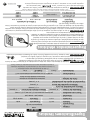
ROU-NX3
16686
60 Hz
Rebajadora de base fija
11.3 A 1 440 W (2 Hp)
Código
Descripción
Tensión Frecuencia
PotenciaCorriente
2” (50 mm)
Máxima capacidad de broca
0 - 2” (50 mm)
Capacidad de ajuste de profundidad
10000 r/min - 25000 r/min
para brocas con zancos de 1/4” (6.5 mm) y 1/2” (13 mm)
Velocidad
Tuerca con mordaza
6” (150 mm) 2" (50 mm)
Diámetro de la base
1 3/4” (45 mm)
Máxima profundidad de corte
Máximo diámetro de la broca
127 V
Especificaciones técnicas
Al operar herramientas eléctricas en exteriores, utilice una extensión
aterrizada marcada como “Uso exterior” marca . Estas extensiones son
especiales para el uso en exteriores y reducen el riesgo de sufrir una descarga eléctrica.
ADVERTENCIA
ADVERTENCIA
ADVERTENCIA
ESPAÑOL
Clase II
16 AWG x 2C con temperatura de aislamiento de 105 °C
Conductores
Aislamiento IP 20
Grado IP
El cable de alimentación tiene sujeta-cables tipo: Y
La clase de construcción de la herramienta es: Aislamiento reforzado.
La clase de aislamiento térmico de los devanados del motor: Clase A
Si el cable de alimentación se daña, éste debe ser reemplazado por el fabricante o Centro de Servicio
Autorizado , con el fin de evitar algún riesgo de descarga o accidente considerable.
La construcción del aislamiento eléctrico de esta herramienta es alterado por salpicaduras o
derramamiento de líquidos durante su operación. No la exponga a la lluvia, líquidos y/o humedad.
Antes de obtener acceso a las terminales, todos los circuitos de alimentación deben ser desconectados.
ADVERTENCIA
ADVERTENCIA
50 minutos de trabajo por 20 minutos
de descanso. Máximo 6 horas diarias.
Ciclo de trabajo

Í
ndice
2
Especificaciones técnicas
Requerimientos eléctricos
Advertencias generales de Seguridad
para herramientas eléctricas
Advertencias de seguridad
para uso de rebajadoras
Partes
Preparación
Puesta en marcha
Operación
Mantenimiento
Solución de problemas
Notas
Centros de servicio autorizados
Póliza de garantía
Guarde este instructivo para futuras referencias.
Los gráficos de este instructivo son para
referencia, pueden variar del aspecto real de la
herramienta.
3
3
4
5
6
7
9
11
12
13
14
15
16
ROU-NX3
Para poder sacar el máximo
provecho de la herramienta,
alargar su vida útil, hacer válida
la garantía en caso de ser
necesario y evitar riesgos o
lesiones graves, es fundamental
leer este instructivo por
completo antes de usar la
herramienta.
ATENCIÓN
ESPAÑOL

ROU-NX3
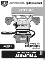
Instructivo de
Lea este instructivo por completo
antes de usar la herramienta.
Rebajadora
de base fija
Código
Este instructivo es para:
16686
Modelo
ROU-NX3
Potencia
1
440 W
ATENCIÓN
ESPAÑOL
ENGLISH
-
 1
1
-
 2
2
-
 3
3
-
 4
4
-
 5
5
-
 6
6
-
 7
7
-
 8
8
-
 9
9
-
 10
10
-
 11
11
-
 12
12
-
 13
13
-
 14
14
-
 15
15
-
 16
16
-
 17
17
-
 18
18
-
 19
19
-
 20
20
-
 21
21
-
 22
22
-
 23
23
-
 24
24
-
 25
25
-
 26
26
-
 27
27
-
 28
28
-
 29
29
-
 30
30
-
 31
31
-
 32
32


Truper ROU-NX3 El manual del propietario
- Categoría
- Herramientas eléctricas
- Tipo
- El manual del propietario
En otros idiomas
- English: Truper ROU-NX3 Owner's manual