QwikProducts X3 Constant Torque ECM Blower Motors Manual de usuario
- Tipo
- Manual de usuario

QwikSwap® X3 Installation Instructions
To replace Constant Torque ECM Blower Motors with a Permanent Split Capacitor
(PSC) Motor and Variable Speed Control Board
CAUTION
To prevent death, injury, or property damage, read and follow all instructions and warnings, including labels shipped with or
attached to unit.
WARNING
Improper installation, adjustment, alteration, service maintenance, or use can cause explosion, fire, electrical shock, or other
conditions that could cause personal injury or property damage. For use by qualified technicians only.
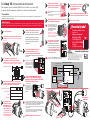
Turn off power.
Note the terminal location and corresponding
color of each wire that connects to the blower
motor. A reference diagram is shown below for
convenience. Disconnect these wires from the motor
Identify a good mounting location with
sufficient clearance or use the supplied
self-drilling sheet metal screws to attach
the mounting bracket.
Verify that you have a Constant Torque Blower
motor such as an X13® or SelecTech® Constant
Torque ECM motor.
Remove the old blower motor and note the shaft
size, frame size (typically 48Y) operating voltage,
direction of rotation and motor horsepower.
Install a new Permanent
Split Capacitor (PSC)
Blower motor with the
specifications noted in
Step 4. Properly ground
the motor and install the
WIRING
DIAGRAM
!
!
Install the power and control wires that
were removed from the old motor onto
When using the optional QT6001
humidity sensor, connect the
sensor following the QT6001
installation instructions.
Using the supplied tie wraps, bundle any excess wires
to avoid interference with the blower.
Reconnect power.
Connect the PSC blower motor power leads
(HIGH, MED, LOW, COM) to the corresponding
output terminals (HIGH, MED, LOW, COM) on the
QwikSwap board.
The terminals on the wires
that were removed from the
old motor MUST BE FULLY
INSULATED or part of a molded
plug that will plug directly into
the QwikSwap X3 board.
If the new PSC blower motor has quick disconnect terminals instead of
wires, you will have to fabricate the four wires (Minimum 14 gauge) with
quick disconnect terminals at each end to connect the High, Medium, Low
and Common connections from the QwikSwap to the PSC motor. Eight
insulated 1/4 inch female quick disconnect terminals have been provided.
If the new blower motor has more than three speeds, use the highest,
lowest and one of the mid-range speeds.
If the new blower motor only has two speed taps, jumper the low- and
medium-speed quick disconnect connectors on the QwikSwap board
together and connect them to the low speed tap on the motor.
If the PSC motor
leads do not
have insulated
terminals, four
insulated 1/4
inch female
quick disconnect
terminals have
been provided to
connect the PSC
power leads to the
QwikSwap Board.
!
1201820001 5008218_REV-D 2232022
!
Attach the thermistor to an evaporator return
bend near the coil inlet.
Route the thermistor wire to the evaporator, and
using the supplied loop clamp,
attach the thermistor to
any return bend near the coil inlet.
Secure the clamp using the supplied
plastic ratchet rivet.
For furnace systems, route the
thermistor wire outside of the
ignition chamber by drilling a 5/16” hole
and using the supplied grommets.
A
B
COM
CAP
CAP
HI
MED
LOW
MOTOR HIGH
MOTOR MED
MOTOR LOW
MOTOR COM
PSC MOTOR
HV AND CONTROL IMPUTS
OUTPUTS
R15
R18
R2
R1
R3
R14
D7 D8
D6 D5 D4 D3 D2
D1
R17 R16
TP4
TP2
C7
U1
C8
C9 C4
R13
R8
U3
R9
R10
R12
TP6
U2
TP5
TP7
TP8
Q1
Q2
Q3
F1
SLOW BLOW
20A, 250VAC
TP3
TP1
R6 R7
J2
J1
MED
LOW
HIGH
DELAY
24V-RED
CONNECT TO
ACTIVATE DELAY
ON BREAK
MOV1
MOV2
K1
K2
K3
MADE IN USA
QwikSwap®QT6100
#5006914 Rev c
Rockledge,
FL
(321) 631-3550
Protected by No 9, 2007, 001
U.S. Patent
C
12345
LG N
(if they are part of a
molded plug, simply
unplug it).
SHAFT SIZE / ROTATION:
FRAME SIZE:
VOLTAGE:
HORSEPOWER:
COM
CAP
CAP
HI
MED
LOW
MOTOR HIGH
MOTOR MED
MOTOR LOW
MOTOR COM
PSC MOTOR
HV AND CONTROL IMPUTS
OUTPUTS
R15
R18
R2
R1
R3
R14
D7 D8
D6 D5 D4 D3 D2
D1
R17 R16
TP4
TP2
C7
U1
C8
C9 C4
R13
R8
U3
R9
R10
R12
TP6
U2
TP5
TP7
TP8
Q1
Q2
Q3
F1
SLOW BLOW
20A, 250VAC
TP3
TP1
R6 R7
J2
J1
MED
LOW
HIGH
DELAY
24V-RED
CONNECT TO
ACTIVATE DELAY
ON BREAK
MOV1
MOV2
K1
K2
K3
MADE IN USA
QwikSwap®QT6100
#5006914 Rev c
Rockledge,
FL
(321) 631-3550
Protected by No 9, 2007, 001
U.S. Patent
C
COM
L G N
HIGH
MED
LOW
HV AND CONTROL INPUTS
MOTOR
OUTPUTS
1 2 3 4 5
MOV1
QwikSwap™ QT6100
MADE IN THE USA / PATENTS PENDING
#5006914 Rev X
Rockledge, FL
(321) 631-3550
HUMIDITY
SENSOR
Thermistor
U1
J4
J2
USE QT6001
R6
C1
C2 C3
R2
C6
+
R1
C4
C8
C9
R10 R9 R8
C5
R5
R7
U2
K1
K2
K3
R4
R3
Q3 Q2 Q1
U3
C7
1
1
J1 J5 J3
DPAK
TO-252
F1
20A, 250VAC
SLOW BLOW
D6 D5 D4 D3 D3
D1
COM
CAP
CAP
HI
MED
LOW
MOTOR HIGH
MOTOR MED
MOTOR LOW
MOTOR COM
PSC MOTOR
HV AND CONTROL IMPUTS
OUTPUTS
R15
R18
R2
R1
R3
R14
D7 D8
D6 D5 D4 D3 D2
D1
R17 R16
TP4
TP2
C7
U1
C8
C9 C4
R13
R8
U3
R9
R10
R12
TP6
U2
TP5
TP7
TP8
Q1
Q2
Q3
F1
SLOW BLOW
20A, 250VAC
TP3
TP1
R6 R7
J2
J1
MED
LOW
HIGH
DELAY
24V-RED
CONNECT TO
ACTIVATE DELAY
ON BREAK
MOV1
MOV2
K1
K2
K3
MADE IN USA
QwikSwap®QT6100
#5006914 Rev c
Rockledge,
FL
(321) 631-3550
Protected by No 9, 2007, 001
U.S. Patent
WARNING: Do not jumper the motor windings.
Mount the QwikSwap
board to its mounting bracket
or mount flat using PCB backer
board tabs/holes
Secure the QwikSwap to the bracket using the
supplied plastic clips.
Press the clips through the bracket holes until
the clips snap in place.
!
200 Yellow Place, Rockledge, FL 32955 / 321-631-3550
All marks shown within this document are properties of their respective owners, X13® is a registered
Trademark of Regal Beloit®. SelecTech®, Emerson®, U.S. Motors® and Nidec® are registered trademarks
of Nidec Motor Corporation. QwikProducts® and QwikSwap® are registered trademarks of
Mainstream Engineering Corporation®, Rockledge, Florida 32955, (321) 631-3550
© 2022 Mainstream Engineering Corporation . All rights reserved.
U.S. Patents #9,207,001, #9,417,005 and Other Patents Pending U.S.A. INNOVATION
Need Help?...
XView an online video installation
tutorial at www.qwik.com/qwik-swap/
XScan this code with your smartphone
to visit our QwikSwap Guide
XChat online
with “Live Help”
at our website.
!
www.qwik.com/qwik-swap/
1 6
7
9
10
11
12
13
14
8
2
3
4
5
capacitor in a location that
protects the terminals from a
short circuit or ground fault.
the matching terminals of the QwikSwap X3 board.
Refer to the wiring diagram created in Step 3 for proper
connection locations.
Typical System Wiring
QwikSwap® X3 Board
L2/N
L1
N
L
G
C
R (Optional)
1
2
3
4
5
COM
SPEED HIGH
PSC
Blower
Motor
To Heater Contactor Coil
MED
LOW
COM
Capacitor
GND
GND
24 VAC
Thermostat
110-240 VAC
These wires previously
plugged into X-13® motor
High
Voltage
Wires
Low Voltage
Thermostat
Wires
GRN
BLU
GRNGRN
GRN
RED
RED
!
To activate a 3-minute delay after
break (which will keep the blower
operating for 3 minutes after the
thermostat stopped the call for
heating or cooling), connect the R
terminal of the QwikSwap X3
board to the red thermostat
wire (24-volt hot leg side of the
transformer).
If the R terminal on the QwikSwap X3 board is left unconnected the X3 will
still function properly, however there will be no delay after break.
MOTOR HIGH
MOTOR MED
MOTOR LOW
MOTOR COM
PSC MOTOR
HV AND CONTROL IMPUTS
OUTPUTS
R15
R18
R2
R1
R3
R14
D7 D8
D6 D5 D4 D3 D2
D1
R17
R16
TP4
TP2
C7
U1
C8
C9 C4
R13
R8
U3
R9
R10
R12
TP6
U2
TP5
TP7
TP8
Q1
Q2
Q3
F1
SLOW BLOW
20A, 250VAC
TP3
TP1
R6 R7
J2
J1
MED
LOW
HIGH
DELAY
24V-RED
CONNECT TO
ACTIVATE DELAY
ON BREAK
MOV1
MOV2
K1
K2
K3
MADE IN USA
QwikSwap™QT6100
#5006914 Rev c
Rockledge,
FL
(321) 631-3550
Protected by No 9, 2007, 001
U.S. Patent
Unit may be mounted flat without
the mounting bracket using the four
mounting tabs/holes on the PCB backer
board and four sheet metal screws.
CW CCW

QwikSwap® X3 Instrucciones de Instalación
Para reemplazar el motor ventilador ECM de torque constante con un motor (PSC)
de capacitor dividido permanente y tablero de control de velocidad variable.
Precaución
Para prevención de muerte, lesiones o daños, lea y siga todas las instrucciones y advertencias, incluyendo etiquetas de
embarque y/o adjuntas a la unidad.
Advertencia
Instalación, ajustes, alteración, servicio de mantenimiento o uso Inapropiado, pueden causar explosión, fuego, choques eléctricos
u otras condiciones que podrían causar lesiones personales o daños materiales. Para uso por personal calificado solamente.
Desactive la alimentación.
Observe la ubicación de la terminal y el color
correspondiente de cada cable que conecta al motor
ventilador. Ver abajo el diagrama de referencia que se muestra.
Desconecte estos cables del motor (si son parte de un molded-plug,
Identique una buena ubicación de montaje
con suciente espacio o utilice la placa de metal
auto-perforada para adjuntar el soporte de montaje.
La unidad puede montarse plana sin el soporte de
montaje usando las cuatro lengüetas / agujeros en
el respaldo del tablero PCB y cuatro tornillos para
lámina de metal.
Compruebe que usted tiene un motor ventilador de torque
constante tal como un X13®, o un motor ECM de torque constante
SelecTech®.
Remueva el motor ventilador viejo y observe la medida
de la echa, el frame size (típicamente 48Y), el Voltaje de
operación, el sentido de rotación y los HP del motor.
Instale un nuevo motor
ventilador (PSC) de capacitor
dividido permanente con
las especicaciones que se
indican en el paso 4. Aterrice
correctamente el motor e instale
Diagramas de
alambrado
!
!
Instalar los cables de alimentación y de control
que fueron removidos del motor viejo en el
Cuando se utiliza el sensor de humedad
opcional QT6001, conectar el sensor
siguiendo las instrucciones de
instalación QT6001.
El uso de las bandas de sujeción suministrados, agrupar los
cables en exceso para evitar la interferencia con el soplador.
Vuelva a conectar la energía.
Conectar los cables de alimentación del motor
ventilador PSC, (ALTA, MEDIA, BAJA y COM) a los
terminales de salida correspondientes (ALTA, MEDIA,
BAJA y COM) en el tablero QwikSwap.
Las terminales de los cables que fueron
removidos del motor viejo, deben ser
totalmente aislados o ser parte de
un molded plug (conector o clavija) que
enchufará directamente sobre el panel
de conexión de QwikSwap X3.
Si el nuevo motor ventilador PSC tiene terminales de desconexión rápida en vez de cables,
usted tendrá que preparar los cuatro cables (calibre 14) con terminales de desconexión rápida
en cada extremo para conectar la Alta, Media, Baja y Común del QwikSwap al motor PSC. Se
han provisto ocho terminales hembra aisladas de ¼”, de desconexión rápida.
Si el nuevo motor ventilador tiene más de tres velocidades, use la mayor, la menor, y una de las
velocidades entre ellas.
Si el nuevo motor ventilador solo cuenta con dos conexiones de velocidad, puentear los
conectores de desconexión rápida de baja y madia velocidad en el tablero QwikSwap y
conectarlos juntos al conector de baja velocidad del motor.
Si los cables del motor PSC no
tienen aisladas las terminales, se
han provisto cuatro terminales
hembra aisladas de desconexión
rápida para conectar los cables de
alimentación del PSC al tablero
QwikSwap.
!
1201820001 5008218_REV-D 2232022
!
Fije el termistor a una “U” del retorno del evaporador
cerca de la entrada del serpentín.
Lleve los cables del termistor al evaporador,
y usando la abrazadera suministrada colocar
el termistor a cualquier curva de retorno
cerca de la entrada del serpentín.
Asegure la abrazadera usando el remache
de plástico suministrado
Para sistemas de horno, lleve el alambre
del termistor fuera de la cámara de encendido
mediante la perforación de un “agujero de 5/16
y el uso de las arandelas suministradas.
A
B
COM
CAP
CAP
HI
MED
LOW
MOTOR HIGH
MOTOR MED
MOTOR LOW
MOTOR COM
PSC MOTOR
HV AND CONTROL IMPUTS
OUTPUTS
R15
R18
R2
R1
R3
R14
D7 D8
D6 D5 D4 D3 D2
D1
R17 R16
TP4
TP2
C7
U1
C8
C9 C4
R13
R8
U3
R9
R10
R12
TP6
U2
TP5
TP7
TP8
Q1
Q2
Q3
F1
SLOW BLOW
20A, 250VAC
TP3
TP1
R6 R7
J2
J1
MED
LOW
HIGH
DELAY
24V-RED
CONNECT TO
ACTIVATE DELAY
ON BREAK
MOV1
MOV2
K1
K2
K3
MADE IN USA
QwikSwap®QT6100
#5006914 Rev c
Rockledge,
FL
(321) 631-3550
Protected by No 9, 2007, 001
U.S. Patent
C
12345
LG N
simplemente desconéctelo).
Medida de la echa / Roración
Tamaño del frame:
Voltaje:
Potencia HP:
COM
CAP
CAP
HI
MED
LOW
MOTOR HIGH
MOTOR MED
MOTOR LOW
MOTOR COM
PSC MOTOR
HV AND CONTROL IMPUTS
OUTPUTS
R15
R18
R2
R1
R3
R14
D7 D8
D6 D5 D4 D3 D2
D1
R17 R16
TP4
TP2
C7
U1
C8
C9 C4
R13
R8
U3
R9
R10
R12
TP6
U2
TP5
TP7
TP8
Q1
Q2
Q3
F1
SLOW BLOW
20A, 250VAC
TP3
TP1
R6 R7
J2
J1
MED
LOW
HIGH
DELAY
24V-RED
CONNECT TO
ACTIVATE DELAY
ON BREAK
MOV1
MOV2
K1
K2
K3
MADE IN USA
QwikSwap®QT6100
#5006914 Rev c
Rockledge,
FL
(321) 631-3550
Protected by No 9, 2007, 001
U.S. Patent
C
COM
L G N
HIGH
MED
LOW
HV AND CONTROL INPUTS
MOTOR
OUTPUTS
1 2 3 4 5
MOV1
QwikSwap™ QT6100
MADE IN THE USA / PATENTS PENDING
#5006914 Rev X
Rockledge, FL
(321) 631-3550
HUMIDITY
SENSOR
Thermistor
U1
J4
J2
USE QT6001
R6
C1
C2 C3
R2
C6
+
R1
C4
C8
C9
R10 R9 R8
C5
R5
R7
U2
K1
K2
K3
R4
R3
Q3 Q2 Q1
U3
C7
1
1
J1 J5 J3
DPAK
TO-252
F1
20A, 250VAC
SLOW BLOW
D6 D5 D4 D3 D3
D1
COM
CAP
CAP
HI
MED
LOW
MOTOR HIGH
MOTOR MED
MOTOR LOW
MOTOR COM
PSC MOTOR
HV AND CONTROL IMPUTS
OUTPUTS
R15
R18
R2
R1
R3
R14
D7 D8
D6 D5 D4 D3 D2
D1
R17 R16
TP4
TP2
C7
U1
C8
C9 C4
R13
R8
U3
R9
R10
R12
TP6
U2
TP5
TP7
TP8
Q1
Q2
Q3
F1
SLOW BLOW
20A, 250VAC
TP3
TP1
R6 R7
J2
J1
MED
LOW
HIGH
DELAY
24V-RED
CONNECT TO
ACTIVATE DELAY
ON BREAK
MOV1
MOV2
K1
K2
K3
MADE IN USA
QwikSwap®QT6100
#5006914 Rev c
Rockledge,
FL
(321) 631-3550
Protected by No 9, 2007, 001
U.S. Patent
ADVERTENCIA. No puentear las bobinas del motor
Montar eñ tablero QwikSwap a su
soporte de montaje, o a montaje plano
a través de los oricios del tablero.
Asegure el QwikSwap al soporte usando los clips plásticos
suministrados.
Presione los clips a través de los oricios del soporte hasta
los clips encajen en su sitio.
!
200 Yellow Place, Rockledge, FL 32955 / 321-631-3550
Todas las marcas que se muestran en este documento son propiedad de sus respectivos dueños, X13®
es una marca registrada de Regal Beloit®. SelecTech®, Emerson®, U.S. Motors® y Nidec® son marcas
registradas de Nidec Motor Corporation. QwikProducts® y QwikSwap® son marcas comerciales
registradas de Mainstream Engineering Corporation, Rockledge, Florida 32955, (321) 631-3550
© 2022 Mainstream Engineering Corporation, Reservados todos los derechos.
Patentes de EE. UU. # 9,207,001, # 9,417,005 y otras patentes pendientes U.S.A. INNOVATION
¿Necesita Ayuda?
XVer en lìnea, el video tutorial de
instalación en…
www.qwik.com/qwik-swap/
XEscanea este código
con tu smartphone para
visite nuestra Guía QwikSwap
XChat en línea
en “Live Help” en nuestro website
!
www.qwik.com/qwik-swap/
1 6
7
9
10
11
12
13
14
8
2
3
4
5
el capacitor de manera que las
terminales queden protegidas contra
corto circuito o falla de tierra.
conector de terminales de la tarjeta QwikSwap X3.
Consulte el diagrama de cableado del paso 3 para la correcta forma
de conexión.
Sistema típico de alambrado
QwikSwap® X3 Board
L2/N
L1
N
L
G
C
R (Optional)
1
2
3
4
5
COM
SPEED HIGH
PSC
Blower
Motor
To Heater Contactor Coil
MED
LOW
COM
Capacitor
GND
GND
24 VAC
Thermostat
110-240 VAC
Estos cables previamente
enchufado en X-13® motor
Cables
de
alto
voltaje
Cables
de bajo
voltaje del
termostato
GRN
BLU
GRNGRN
GRN
RED
RED
!
Para activar un retardo de 3 minutos
después del paro (el cual mantendrá
al ventilador funcionando por 3 minutos
después de que el termostato cortó la señal
de calefacción o enfriamiento), conecte la
terminal “R” del tablero QwikSwap X3
al cable rojo del termostato (del lado vivo
del transformador de 24 Volt).
Si la terminal R del tablero QwikSwap X3 se deja sin conectar, el X3 seguirà funcionando
correctamente, sin embargo no habrá ningún retraso después del corte.
MOTOR HIGH
MOTOR MED
MOTOR LOW
MOTOR COM
PSC MOTOR
HV AND CONTROL IMPUTS
OUTPUTS
R15
R18
R2
R1
R3
R14
D7 D8
D6 D5 D4 D3 D2
D1
R17
R16
TP4
TP2
C7
U1
C8
C9 C4
R13
R8
U3
R9
R10
R12
TP6
U2
TP5
TP7
TP8
Q1
Q2
Q3
F1
SLOW BLOW
20A, 250VAC
TP3
TP1
R6 R7
J2
J1
MED
LOW
HIGH
DELAY
24V-RED
CONNECT TO
ACTIVATE DELAY
ON BREAK
MOV1
MOV2
K1
K2
K3
MADE IN USA
QwikSwap™QT6100
#5006914 Rev c
Rockledge,
FL
(321) 631-3550
Protected by No 9, 2007, 001
U.S. Patent
CW CCW
-
 1
1
-
 2
2

