
4
1
2
1
2
3
4
1
2
3
1
2 3
VE601 DVI HDBaseT-Lite Extender Quick Start Guide VE601 Alargador DVI HDBaseT-Lite Guía rápida
Système d'extension HDBaseT-Lite DVI VE601 – Guide de démarrage rapide Estensore DVI HDBaseT-Lite VE601 - Guida rapida
VE601 HDBaseT-Lite DVI-Verlängerung Kurzanleitung Краткое руководство пользователя удлинителя DVI HDBaseT-Lite VE601
www.aten.com www.aten.com
www.aten.com www.aten.com
www.aten.com www.aten.com
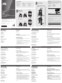
Package Contents
Hardware Review
A
VE601T Front and Rear View
1. F/W Upgrade Port
2. DVI Input Port
3. Power Jack
4. HDBaseT Output Port
VE601T Top View
1. Link LED
2. Power LED
VE601R Front and Rear View
1. Power Jack
2. HDBaseT Input Port
3. F/W Upgrade Port
4. DVI Output Port
Presentación del hardware
A
VE601T – Vistas frontal y posterior
1. Puerto de actualización del fi rmware
2. Puerto de entrada DVI
3. Entrada de alimentación
4. Puerto de salida HDBaseT
VE601T – Panel superior
1. Indicador de enlace (Link)
2. Indicador de alimentación
VE601R – Vistas frontal y posterior
1. Entrada de alimentación
2. Puerto de entrada HDBaseT
3. Puerto de actualización del fi rmware
4. Puerto de salida DVI
VE601R – Panel superior
1. LED de salida de videoI
Description de l’appareil
A
Vue avant et arrière VE601T
1. Port de mise à niveau du microprogramme
2. Port d’entrée DVI
3. Prise d’alimentation
4. Port de sortie HDBaseT
Vue supérieure du VE601T
1. Voyant de liaison (Link)
2. Voyant d’alimentation
Vue avant et arrière VE601R
1. Prise d’alimentation
2. Port d’entrée HDBaseT
3. Port de mise à niveau du microprogramme
4. Port de sortie DVI
Vue supérieure du VE601R
1. Diode de sortie video
Hardware
A
VE601T – vista anteriore e posteriore
1. Porta per aggiornamento F/W
2. Porta d’ingresso DVI
3. Presa d’alimentazione
4. Porta d’uscita HDBaseT
VE601T – vista superiore
1. LED di collegamento
2. LED d’alimentazione
VE601R – vista anteriore e posteriore
1. Presa d’alimentazione
2. Porta d’ingresso HDBaseT
3. Porta per aggiornamento F/W
4. Porta d’uscita DVI
VE601R – vista superiore
1. LED uscita video
Hardwareübersicht
A
VE601T – Vorder- und Rückseite
1. Port für Firmwareaktualisierung
2. DVI-Eingang
3. Stromeingangsbuchse
4. HDBaseT-Ausgang
VE601T - Oberseite
1. Verbindungsanzeige
2. LED-Betriebsanzeige
VE601R – Vorder- und Rückseite
1. Stromeingangsbuchse
2. HDBaseT-Eingangsport
3. Port für Firmwareaktualisierung
4. DVI-Ausgang
VE601R - Oberseite
1. Video Ausgang LED
Обзор оборудования
A
Вид спереди и сзади VE601T
1. Порт обновления прошивки
2. Вход DVI
3. Гнездо питания
4. Выход HDBaseT
Вид сверху VE601T
1. Индикатор соединения
2. Индикатор питания
Вид спереди и сзади VE601R
1. Гнездо питания
2. Вход HDBaseT
3. Порт обновления прошивки
4. Выход DVI
Вид сверху VE601R
1. Индикатор видеовыхода
VE601R Top View
1. Video Out LED
2. Link LED
3. Power LED
Trouble Shooting
The Firmware upgrade port is reserved for tech support. If you would like to do
fi rmware upgrade yourself, please contact your dealer.
Hardware Installation
B
1. Connect the DVI Input Port on the VE601T to the DVI Output Port on your
video source device using DVI cable.
2. Connect one end of the RJ-45 cable to the HDBaseT output port on the
transmitter. Then connect the other end of the RJ-45 cable to the HDBaseT
input port on the receiver.
3. Connect the DVI Output Port on the VE601R to the DVI Input Port on your
video display device using DVI Cable.
4. Plug the power adapter cable into the power jack on the VE601.
2. Indicador de enlace (Link)
3. Indicador de alimentación
Solución de problemas
El puerto para actualizaciones del fi rmware está reservado para fi nes de
soporte técnico. Si desea actualizar el fi rmware por su cuenta, póngase en
contacto con su vendedor habitual.
Instalar el hardware
B
1. Conecte el puerto de entrada DVI del VE601T al puerto de salida DVI de su
dispositivo fuente de señal gráfi ca. Para ello, emplee un cable DVI.
2. Conecte un extremo del cable de RJ-45 al puerto de salida HDBaseT del
transmisor. Luego conecte el otro extremo del cable de RJ-45 al puerto de
entrada HDBaseT del receptor.
3. Conecte el puerto de salida DVI del VE601R al puerto de entrada DVI de su
dispositivo de visualización. Para ello, emplee un cable DVI.
4. Conecte el cable del adaptador de alimentación a la entrada de
alimentación del VE601.
2. Voyant de liaison (Link)
3. Voyant d’alimentation
Résolution des problèmes
Le port de mise à niveau du microprogramme est réservé à l’assistance
technique. Si vous souhaitez effectuer vous-même la mise à niveau du
microprogramme, veuillez contacter votre revendeur.
Installation du matériel
B
1. Connectez le port d’entrée DVI du module VE601T au port de sortie DVI de
votre périphérique vidéo source à l’aide d’un câble DVI.
2. Connectez une extrémité du câble RJ-45 au port de sortie HDBaseT de
l’émetteur. Ensuite, connectez l’autre extrémité du câble RJ-45 au port
d’entrée HDBaseT du récepteur.
3. Connectez le port de sortie DVI du module VE601R au port d’entrée DVI de
votre périphérique vidéo source à l’aide d’un câble DVI.
4. Branchez le câble de l’adaptateur secteur dans la prise d’alimentation du
module VE601.
2. LED di collegamento
3. LED d’alimentazione
Risoluzione dei problemi
La porta per l’aggiornamento del fi rmware è riservata all’assistenza tecnica.
Se si desidera effettuare in proprio l’aggiornamento, rivolgersi al proprio
rivenditore.
Installazione dell’hardware
B
1. Collegare la porta d’ingresso DVI del VE601T alla porta di uscita DVI del
dispositivo video sorgente tramite un cavo DVI.
2. Collegare un’estremità del cavo RJ-45 alla porta di uscita HDBaseT del
trasmettitore. Collegare quindi l’altra estremità del cavo RJ-45 alla porta
d’ingresso HDBaseT del ricevitore.
3. Collegare la porta d’uscita DVI del VE601R alla porta d’ingresso DVI del
dispositivo video sorgente tramite un cavo DVI.
4. Inserire il cavo dell’alimentatore nella presa d’alimentazione del VE601.
2. Verbindungsanzeige
3. LED-Betriebsanzeige
Problemlösung
Der Port zur Firmwareaktualisierung ist nur für Supportzwecke vorgesehen.
Falls Sie selbst eine Firmwareaktualisierung durchführen möchten, wenden Sie
sich an Ihren Fachhändler.
Hardware installieren
B
1. Verbinden Sie den DVI-Eingang am VE601T mit dem DVI-Ausgang Ihrer
Bildsignalquelle. Verwenden Sie dazu ein passendes DVI-Kabel.
2. Verbinden Sie das eine Ende des RJ-45-Kabels mit dem HDBaseT-Ausgang
der Sendeeinheit. Verbinden Sie anschließend das andere Ende des RJ-45-
Kabels mit dem HDBaseT-Eingang der Empfangseinheit.
3. Verbinden Sie den DVI-Ausgang am VE601R mit dem DVI-Eingang Ihres
Anzeigegerätes. Verwenden Sie dazu ein passendes DVI-Kabel.
4. Verbinden Sie das Kabel des Netzteils mit der Stromeingangsbuchse am
VE601.
2. Индикатор соединения
3. Индикатор питания
Поиск и устранение неисправностей
Порт обновления прошивки предназначен для специалистов службы
технической поддержки. Для самостоятельного обновления прошивки
свяжитесь с дилером.
Установка оборудования
B
1. Соедините вход DVI устройства VE601T с выходом DVI источника видео
с помощью кабеля DVI.
2. Подключите один конец кабеля RJ-45 к выходу HDBaseT передатчика.
Затем подключите другой конец кабеля RJ-45 к входу HDBaseT
приемника.
3. Соедините выход DVI устройства VE601R с входом DVI источника видео
с помощью кабеля DVI.
4. Включите кабель адаптера питания в гнездо питания устройства VE601.
A
Hardware Review
B
Hardware Installation
© Copyright 2015 ATEN
®
International Co., Ltd.
ATEN and the ATEN logo are trademarks of ATEN International Co., Ltd. All rights reserved. All
other trademarks are the property of their respective owners.
This product is RoHS compliant.
Part No. PAPE-1223-E30G Printing Date: 06/2015
DVI HDBaseT-Lite Extender
Quick Start Guide
VE601
ATEN VanCryst
™
VE601
1 VE601T/R DVI HDBaseT-Lite
Extender
2 Power Adapters
1 User Instructions
VE601T
1 VE601T DVI HDBaseT-Lite
Transmitter
1 Power Adapter
1 User Instructions
VE601R
1 VE601R DVI HDBaseT-Lite
Receiver
1 Power Adapter
1 User Instructions
DVI Source
Device
VE601R
VE601T
DVI Display
1
2
3
4
4
Important Notice
Considering environmental protection, ATEN does not provide a fully printed user manual for this product.
If the information contained in the Quick Start Guide is not enough for you to confi gure and operate your
product, please visit our website www.aten.com, and download the full user manual.
Online Registration
http://eservice.aten.com
Technical Phone Support
International:
886-2-86926959
All information, documentation, fi rmware, software utilities, and specifi cations contained in this package are subject to
change without prior notifi cation by the manufacturer. Please visit our website http://www.aten.com/download/?cid=dds
for the most up-to-date versions.
EMC Information
FEDERAL COMMUNICATIONS COMMISSION INTERFERENCE STATEMENT:
This equipment has been tested and found to comply with the limits for a Class A digital device, pursuant to Part 15 of the
FCC Rules. These limits are designed to provide reasonable protection against harmful interference when the equipment is
operated in a commercial environment. This equipment generates, uses, and can radiate radio frequency energy and, if not
installed and used in accordance with the instruction manual, may cause harmful interference to radio communications.
Operation of this equipment in a residential area is likely to cause harmful interference in which case the user will be
required to correct the interference at his own expense.
FCC Caution: Any changes or modifi cations not expressly approved by the party responsible for compliance could void the
user's authority to operate this equipment.
CE Warning: This is a class A product. In a domestic environment this product may cause radio interference in which case
the user may be required to take adequate measures.
Suggestion: Shielded twisted pair (STP) cables must be used with the unit to ensure compliance with FCC & CE standards.
This device complies with Part 15 of the FCC Rules. Operation is subject to the following two conditions:(1) this device mat
not cause harmful interference, and(2) this device must accept any interference received, including interference that may
cause undesired operation.
The following contains information that relates to China:
North America:
1-888-999-ATEN Ext: 4988
United Kingdom:
44-8-4481-58923
VE601T Front and Rear View
VE601R Front and Rear View
VE601T Top View
VE601R Top View
이 기기는 업무용(A급) 전자파 적합기기로서 판매자 또는 사용자는 이점을 주의하시기 바라며, 가정외
의 지역에서 사용하는 것을 목적으로합니다.
La página se está cargando...
Transcripción de documentos
Package Contents VE601 1 VE601T/R DVI HDBaseT-Lite Extender 2 Power Adapters 1 User Instructions VE601T 1 VE601T DVI HDBaseT-Lite Transmitter 1 Power Adapter 1 User Instructions Important Notice B VE601R 1 VE601R DVI HDBaseT-Lite Receiver 1 Power Adapter 1 User Instructions Considering environmental protection, ATEN does not provide a fully printed user manual for this product. If the information contained in the Quick Start Guide is not enough for you to configure and operate your product, please visit our website www.aten.com, and download the full user manual. Hardware Installation VE601R Online Registration http://eservice.aten.com Technical Phone Support International: 886-2-86926959 DVI Display 3 A ATEN VanCryst™ VE601 VE601T Front and Rear View 2 3 4 4 EMC Information FEDERAL COMMUNICATIONS COMMISSION INTERFERENCE STATEMENT: DVI HDBaseT-Lite Extender Quick Start Guide VE601T 1 2 VE601R Top View VE601R Front and Rear View 1 3 2 2 4 4 1 This product is RoHS compliant. Part No. PAPE-1223-E30G The following contains information that relates to China: VE601T Top View Hardware Review 1 © Copyright 2015 ATEN® International Co., Ltd. ATEN and the ATEN logo are trademarks of ATEN International Co., Ltd. All rights reserved. All other trademarks are the property of their respective owners. DVI Source Device Printing Date: 06/2015 1 2 3 VE601 DVI HDBaseT-Lite Extender Quick Start Guide Hardware Review www.aten.com Trouble Shooting The Firmware upgrade port is reserved for tech support. If you would like to do firmware upgrade yourself, please contact your dealer. VE601T Top View 1. Link LED 2. Power LED Hardware Installation B 1. Connect the DVI Input Port on the VE601T to the DVI Output Port on your video source device using DVI cable. 2. Connect one end of the RJ-45 cable to the HDBaseT output port on the transmitter. Then connect the other end of the RJ-45 cable to the HDBaseT input port on the receiver. 3. Connect the DVI Output Port on the VE601R to the DVI Input Port on your video display device using DVI Cable. 4. Plug the power adapter cable into the power jack on the VE601. VE601R Front and Rear View 1. Power Jack 2. HDBaseT Input Port 3. F/W Upgrade Port 4. DVI Output Port Système d'extension HDBaseT-Lite DVI VE601 – Guide de démarrage rapide Description de l’appareil A Vue avant et arrière VE601T 1. Port de mise à niveau du microprogramme 2. Port d’entrée DVI 3. Prise d’alimentation 4. Port de sortie HDBaseT Vue supérieure du VE601T 1. Voyant de liaison (Link) 2. Voyant d’alimentation Vue avant et arrière VE601R 1. Prise d’alimentation 2. Port d’entrée HDBaseT 3. Port de mise à niveau du microprogramme 4. Port de sortie DVI Vue supérieure du VE601R 1. Diode de sortie video www.aten.com Résolution des problèmes Le port de mise à niveau du microprogramme est réservé à l’assistance technique. Si vous souhaitez effectuer vous-même la mise à niveau du microprogramme, veuillez contacter votre revendeur. Installation du matériel 1. Connectez le port d’entrée DVI du module VE601T au port de sortie DVI de votre périphérique vidéo source à l’aide d’un câble DVI. 2. Connectez une extrémité du câble RJ-45 au port de sortie HDBaseT de l’émetteur. Ensuite, connectez l’autre extrémité du câble RJ-45 au port d’entrée HDBaseT du récepteur. 3. Connectez le port de sortie DVI du module VE601R au port d’entrée DVI de votre périphérique vidéo source à l’aide d’un câble DVI. 4. Branchez le câble de l’adaptateur secteur dans la prise d’alimentation du module VE601. VE601 HDBaseT-Lite DVI-Verlängerung Kurzanleitung Hardwareübersicht A VE601T – Vorder- und Rückseite 1. Port für Firmwareaktualisierung 2. DVI-Eingang 3. Stromeingangsbuchse 4. HDBaseT-Ausgang VE601T - Oberseite 1. Verbindungsanzeige 2. LED-Betriebsanzeige VE601R – Vorder- und Rückseite 1. Stromeingangsbuchse 2. HDBaseT-Eingangsport 3. Port für Firmwareaktualisierung 4. DVI-Ausgang VE601R - Oberseite 1. Video Ausgang LED B www.aten.com VE601T – Panel superior 1. Indicador de enlace (Link) 2. Indicador de alimentación VE601R – Panel superior 1. LED de salida de videoI A VE601T – vista anteriore e posteriore 1. Porta per aggiornamento F/W 2. Porta d’ingresso DVI 3. Presa d’alimentazione 4. Porta d’uscita HDBaseT VE601T – vista superiore 1. LED di collegamento 2. LED d’alimentazione www.aten.com 2. Indicador de enlace (Link) 3. Indicador de alimentación Solución de problemas El puerto para actualizaciones del firmware está reservado para fines de soporte técnico. Si desea actualizar el firmware por su cuenta, póngase en contacto con su vendedor habitual. B 1. Conecte el puerto de entrada DVI del VE601T al puerto de salida DVI de su dispositivo fuente de señal gráfica. Para ello, emplee un cable DVI. 2. Conecte un extremo del cable de RJ-45 al puerto de salida HDBaseT del transmisor. Luego conecte el otro extremo del cable de RJ-45 al puerto de entrada HDBaseT del receptor. 3. Conecte el puerto de salida DVI del VE601R al puerto de entrada DVI de su dispositivo de visualización. Para ello, emplee un cable DVI. 4. Conecte el cable del adaptador de alimentación a la entrada de alimentación del VE601. www.aten.com 2. LED di collegamento 3. LED d’alimentazione Risoluzione dei problemi La porta per l’aggiornamento del firmware è riservata all’assistenza tecnica. Se si desidera effettuare in proprio l’aggiornamento, rivolgersi al proprio rivenditore. Installazione dell’hardware VE601R – vista anteriore e posteriore 1. Presa d’alimentazione 2. Porta d’ingresso HDBaseT 3. Porta per aggiornamento F/W 4. Porta d’uscita DVI B 1. Collegare la porta d’ingresso DVI del VE601T alla porta di uscita DVI del dispositivo video sorgente tramite un cavo DVI. 2. Collegare un’estremità del cavo RJ-45 alla porta di uscita HDBaseT del trasmettitore. Collegare quindi l’altra estremità del cavo RJ-45 alla porta d’ingresso HDBaseT del ricevitore. 3. Collegare la porta d’uscita DVI del VE601R alla porta d’ingresso DVI del dispositivo video sorgente tramite un cavo DVI. 4. Inserire il cavo dell’alimentatore nella presa d’alimentazione del VE601. VE601R – vista superiore 1. LED uscita video Краткое руководство пользователя удлинителя DVI HDBaseT-Lite VE601 Problemlösung Der Port zur Firmwareaktualisierung ist nur für Supportzwecke vorgesehen. Falls Sie selbst eine Firmwareaktualisierung durchführen möchten, wenden Sie sich an Ihren Fachhändler. 1. Порт обновления прошивки 2. Вход DVI 3. Гнездо питания 4. Выход HDBaseT A Вид спереди и сзади VE601T 1. Verbinden Sie den DVI-Eingang am VE601T mit dem DVI-Ausgang Ihrer Bildsignalquelle. Verwenden Sie dazu ein passendes DVI-Kabel. 2. Verbinden Sie das eine Ende des RJ-45-Kabels mit dem HDBaseT-Ausgang der Sendeeinheit. Verbinden Sie anschließend das andere Ende des RJ-45Kabels mit dem HDBaseT-Eingang der Empfangseinheit. 3. Verbinden Sie den DVI-Ausgang am VE601R mit dem DVI-Eingang Ihres Anzeigegerätes. Verwenden Sie dazu ein passendes DVI-Kabel. 4. Verbinden Sie das Kabel des Netzteils mit der Stromeingangsbuchse am VE601. All information, documentation, firmware, software utilities, and specifications contained in this package are subject to change without prior notification by the manufacturer. Please visit our website http://www.aten.com/download/?cid=dds for the most up-to-date versions. Estensore DVI HDBaseT-Lite VE601 - Guida rapida Обзор оборудования B 이 기기는 업무용(A급) 전자파 적합기기로서 판매자 또는 사용자는 이점을 주의하시기 바라며, 가정외 의 지역에서 사용하는 것을 목적으로합니다. Instalar el hardware VE601R – Vistas frontal y posterior 1. Entrada de alimentación 2. Puerto de entrada HDBaseT 3. Puerto de actualización del firmware 4. Puerto de salida DVI 2. Verbindungsanzeige 3. LED-Betriebsanzeige Hardware installieren A VE601T – Vistas frontal y posterior 1. Puerto de actualización del firmware 2. Puerto de entrada DVI 3. Entrada de alimentación 4. Puerto de salida HDBaseT Hardware 2. Voyant de liaison (Link) 3. Voyant d’alimentation This equipment has been tested and found to comply with the limits for a Class A digital device, pursuant to Part 15 of the FCC Rules. These limits are designed to provide reasonable protection against harmful interference when the equipment is operated in a commercial environment. This equipment generates, uses, and can radiate radio frequency energy and, if not installed and used in accordance with the instruction manual, may cause harmful interference to radio communications. Operation of this equipment in a residential area is likely to cause harmful interference in which case the user will be required to correct the interference at his own expense. FCC Caution: Any changes or modifications not expressly approved by the party responsible for compliance could void the user's authority to operate this equipment. CE Warning: This is a class A product. In a domestic environment this product may cause radio interference in which case the user may be required to take adequate measures. Suggestion: Shielded twisted pair (STP) cables must be used with the unit to ensure compliance with FCC & CE standards. This device complies with Part 15 of the FCC Rules. Operation is subject to the following two conditions:(1) this device mat not cause harmful interference, and(2) this device must accept any interference received, including interference that may cause undesired operation. VE601 Alargador DVI HDBaseT-Lite Guía rápida Presentación del hardware VE601R Top View 1. Video Out LED 2. Link LED 3. Power LED A VE601T Front and Rear View 1. F/W Upgrade Port 2. DVI Input Port 3. Power Jack 4. HDBaseT Output Port North America: 1-888-999-ATEN Ext: 4988 United Kingdom: 44-8-4481-58923 Вид сверху VE601T 1. Индикатор соединения 2. Индикатор питания Вид спереди и сзади VE601R 1. Гнездо питания 2. Вход HDBaseT 3. Порт обновления прошивки 4. Выход DVI Вид сверху VE601R 1. Индикатор видеовыхода www.aten.com 2. Индикатор соединения 3. Индикатор питания Поиск и устранение неисправностей Порт обновления прошивки предназначен для специалистов службы технической поддержки. Для самостоятельного обновления прошивки свяжитесь с дилером. Установка оборудования B 1. Соедините вход DVI устройства VE601T с выходом DVI источника видео с помощью кабеля DVI. 2. Подключите один конец кабеля RJ-45 к выходу HDBaseT передатчика. Затем подключите другой конец кабеля RJ-45 к входу HDBaseT приемника. 3. Соедините выход DVI устройства VE601R с входом DVI источника видео с помощью кабеля DVI. 4. Включите кабель адаптера питания в гнездо питания устройства VE601.-
 1
1
-
 2
2


ATEN VE601T Guía de inicio rápido
- Tipo
- Guía de inicio rápido
- Este manual también es adecuado para
en otros idiomas
- français: ATEN VE601T Guide de démarrage rapide
- italiano: ATEN VE601T Guida Rapida
- English: ATEN VE601T Quick start guide
- Deutsch: ATEN VE601T Schnellstartanleitung
- русский: ATEN VE601T Инструкция по началу работы
- português: ATEN VE601T Guia rápido
- 日本語: ATEN VE601T クイックスタートガイド
Artículos relacionados
-
ATEN VE3912T Guía de inicio rápido
-
ATEN VE2812AT Guía de inicio rápido
-
-
-
-
ATEN VE2812AEUT Guía de inicio rápido
-
ATEN VE2812AUST Guía de inicio rápido
-
-
-
ATEN VE801 Guía de inicio rápido