Craftsman 247250030 El manual del propietario
- Categoría
- Cortadoras de césped
- Tipo
- El manual del propietario

per'ator's nual
I:RRFrSMRN°
ZERO=TURN RIDER
27 HP, 48" MOWER DECK
Model No. 247,25003
CAUTION: Before using this product,
read this manual and follow all safety
rules and operating instructions,
, SAFETY
ASSEMBLY
OPERATION
MAINTENANCE
PARTS LIST
o ESPANOL
Sears Brands Management Corporation, Hoffman Estates, IL 60179, U.S.A.
Visit our website: www.craftsman.com
FormNo.769-07656
(February22,2012)

Warranty Statement .................................. Page 2
Safe Operation Practices .......................... Pages 3-8
Assembly .................................................. Pages 9-11
Operation .................................................. Pages 12-21
Service and Maintenance ......................... Pages 22-33
Off-Season Storage .................................. Page 34
Troubleshooting ........................................ Page 35-36
Parts List ..................................................... Pages 38-61
Engine Parts List ....................................... Pages 62-75
Labels ....................................................... Page 76
Repair Protection Agreement ................... Page 79
Espafiol ..................................................... Page 84
Service Numbers ...................................... Back Cover
CRAFTSMAN FULL WARRANTY
FORTHREEYEARSfromthedateof purchase,all non-expendabbpartsofthis ridingequipmentarewarrantedagainstanydefectsinmaterial
orworkmanship.Adefectivenon-expendablepartwillreceivefreein-homerepairor replacementif repairis impossible.
FOR90 DAYSfromthedateofpurchase,thebattery(anexpendablepart)ofthis ridingequipmentiswarrantedagainstanydefectsinmaterialor
workmanship(ourtestingprovesthat itwillnotholda charge).A defectivebatterywillreceivefreein-homereplacement.
WARRANTYSERVICE
Forwarrantycoveragedetailstoobtainfree repairor replacement,call1-800-659-5917or visitthewebsite:www.craftsman.com
Inallcasesabove,if partrepairor replacementis impossible,theridingequipmentwillbe replacedfreeofchargewiththesameor anequivalent
model.
Alloftheabovewarrantycoverageisvoidifthisridingequipmentiseverusedwhileprovidingcommercialservicesor if rentedtoanotherperson.
ThiswarrantycoversONLYdefectsin materialandworkmanship.WarrantycoveragedoesNOTinclude:
• Expendableparts(exceptbattery)thatcanwearoutfromnormalusewithinthewarrantyperiod,includingbutnotlimitedtoblades,spark
plugs,air cleaners,belts,andoilfilters.
• Standardmaintenanceservicing,oilchanges,or tune-ups.
• Tirereplacementor repaircausedbypuncturesfromoutsideobjects,suchasnails,thorns,stumps,or glass.
Tireor wheelreplacementor repairresultingfromnormalwear,accident,or improperoperationor maintenance.
Repairsnecessarybecauseof operatorabuse,includingbutnotlimitedtodamagecausedbytowingobjectsbeyondthecapabilityofthe
ridingequipment,impactingobjectsthatbendtheframe,axleassemblyor crankshaft,orover-speedingtheengine.
• Repairsnecessarybecauseof operatornegligence,includingbutnotlimitedto,electricalandmechanicaldamagecausedbyimproper
storage,failureto usethepropergradeand amountofengineoil,failuretokeepthedeckclearofflammabledebris,orfailuretomaintainthe
ridingequipmentaccordingtotheinstructionscontainedin theoperator'smanual.
• Engine(fuelsystem)cleaningor repairscausedbyfueldeterminedto becontaminatedor oxidized(stale).Ingeneral,fuelshouldbeused
within30 daysof itspurchasedate.
Normaldeteriorationandwearoftheexteriorfinishes,or productlabelreplacement.
o
Thiswarrantygivesyouspecificlegalrights,and youmayalsohaveotherrightswhichvaryfromstatetostate.
Sears BrandsManagementCorporation, Hoffman Estates,IL 60179
EngineOil: 15W-40
Fuel: UnleadedGasoline
SparkPlug: RC12YC
Engine: KohlerSV840-3021
ModelNumber
Serial Number
Dateof Purchase
Recordthemodelnumber,serialnumber,
anddateof purchaseabove.
© KCDIRLLC 2

Thissymbolpointsoutimportantsafetyinstructionswhich,if not
followed,couldendangerthepersonalsafetyand/orpropertyof
yourselfandothers.Readandfollowall instructionsin thismanual
beforeattemptingtooperatethismachine.Failuretocomplywith
theseinstructionsmayresultin personalinjury.Whenyouseethis
symbol,HEEDITSWARNING!
CALIFORNIA PROPOSITION 65
EngineExhaust,someof itsconstituents,andcertainvehicle
componentscontainoremitchemicalsknowntoStateofCalifornia
tocausecancerandbirthdefectsorotherreproductiveharm.
Batteryposts,terminals,and relatedaccessoriescontainleadand
leadcompounds,chemicalsknowntotheStateof Californiato
causecancerandreproductiveharm.Washhandsafterhandling.
Thismachinewasbuilttobeoperatedaccordingtothesafeopera-
tionpracticesinthis manual.Aswithanytypeof powerequipment,
carelessnessorerroron thepartoftheoperatorcanresultin serious
injury.Thismachineiscapableofamputatingfingers,hands,toes
andfeetandthrowingdebris.Failuretoobservethefollowingsafety
instructionscouldresultin seriousinjuryor death.
Your Responsibility--Restricttheuseofthispowermachineto
personswhoread,understandandfollowthewarningsand instruc-
tionsin thismanualandon themachine.
SAVE THESE INSTRUCTIONS!
GENERAL OPERATION
• Read,understand,andfollowall instructionson themachineand
in themanual(s)beforeattemptingtoassembleandoperate.
Keepthis manualina safeplaceforfutureand regularreference
andfororderingreplacementparts.
• Befamiliarwithall controlsandtheirproperoperation.Knowhow
tostopthemachineanddisengagethemquickly.
• Neverallowchildrenunder14yearsofagetooperatethis
machine.Children14andovershouldreadandunderstandthe
instructionsandsafeoperationpracticesin thismanualandon
themachineandshouldbetrainedandsupervisedbyan adult.
• Neverallowadultstooperatethis machinewithoutproper
instruction.
• Tohelpavoidbladecontactor a thrownobjectinjury,keep
bystanders,helpers,childrenandpetsatleast75feetfromthe
machinewhileitisin operation.Stopmachineifanyoneenters
thearea.
• Thoroughlyinspecttheareawheretheequipmentistobe used.
Removeallstones,sticks,wire,bones,toys,andotherforeign
objectswhichcouldbe pickedupandthrownbytheblade(s).
Thrownobjectscancauseseriouspersonalinjury.
• Planyourmowingpatterntoavoiddischargeofmaterialtoward
roads,sidewalks,bystandersandthelike.Also,avoiddischarg-
ingmaterialagainstawallorobstructionwhichmaycause
dischargedmaterialto ricochetbacktowardtheoperator.
• Alwayswearsafetyglassesorsafetygogglesduringoperation
andwhileperforminganadjustmentor repairtoprotectyoureyes.
Thrownobjectswhichricochetcancauseseriousinjurytothe
eyes.
• Wearsturdy,rough-soledworkshoesandclose-fittingslacksand
shirts.Loosefittingclothesandjewelrycanbecaughtin movable
parts.Neveroperatethis machinein barefeetor sandals.
• Beawareofthemowerandattachmentdischargedirectionand
do notpointitatanyone.Donotoperatethemowerwithoutthe
dischargecoverorentiregrasscatcherin its properplace.
• Donotputhandsor feetnearrotatingpartsor underthecutting
deck.Contactwiththeblade(s)canamputatehandsandfeet.
• A missingor damageddischargecovercancausebladecontact
or thrownobjectinjuries.
• Stoptheblade(s)whencrossinggraveldrives,walks,or roads
andwhilenotcuttinggrass.
• Watchfortrafficwhenoperatingnearorcrossingroadways.This
machineisnotintendedforuseonanypublicroadway.
• Donotoperatethemachinewhileundertheinfluenceofalcohol
or drugs.
• Mowonlyindaylightorgoodartificiallight.
• Nevercarrypassengers.
• Backup slowly.Alwayslookdownandbehindbeforeandwhile
backingtoavoida back-overaccident.Beawareand payatten-
tiontothesafetysystemfunctionthatstopspowertothe blades
whendrivingin reverse.If notfunctioningproperly,contactan
authorizeddealerforsafetysysteminspectionand repair.
• Slowdownbeforeturning.Operatethemachinesmoothly.Avoid
erraticoperationandexcessivespeed.
• Disengageblade(s),setparkingbrake,stopengineandwaituntil
theblade(s)cometo acompletestopbeforeremovinggrass
catcher,emptyinggrass,uncloggingchute,removinganygrassor
debris,or makinganyadjustments.
• Neverleavea runningmachineunattended.Alwaysturnoff
blade(s),placedrivecontrollevers fullyoutwardtoeachsidein
neutral,set parkingbrake,stopengineandremovekeybefore
dismounting.
3

• Useextracarewhenloadingorunloadingthemachineintoa
trailerortruck.Thismachineshouldnotbedrivenupor down
ramp(s),becausethemachinecouldtipover,causingserious
personalinjury.Themachinemustbe pushedmanuallyon
ramp(s)to loador unloadproperly.
• Mufflerandenginebecomehotandcancausea burn.Donot
touch.
• Checkoverheadclearancescarefullybeforedrivingunderlow
hangingtreebranches,wires,dooropeningsetc.,wherethe
operatormaybestruckor pulledfromthemachine,whichcould
resultinseriousinjury.
• Disengageallattachmentclutches,settheparkingbraketothe
'on'positionandmovethe RHand LHdrivecontrolleversfully
outwardto eachsidetotheneutralpositionbeforeattemptingto
starttheengine.
• Yourmachineisdesignedto cutnormalresidentialgrassofa
heightnomorethan10".Donotattemptto mowthroughunusually
tall,drygrass(e.g.,pasture)orpilesofdryleaves.Drygrassor
leavesmaycontacttheengineexhaustand/orbuilduponthe
mowerdeckpresentinga potentialfirehazard.
• Useonlyaccessoriesandattachmentsapprovedforthis machine
bythemachinemanufacturer.Read,understandandfollowall
instructionsprovidedwiththeapprovedaccessoryor attachment.
• Dataindicatesthatoperators,age60yearsandabove,are
involvedin a largepercentageofridingmower-relatedinjuries.
Theseoperatorsshouldevaluatetheirabilitytooperatetheriding
mowersafelyenoughto protectthemselvesandothersfrom
seriousinjury.
• If situationsoccurwhicharenotcoveredinthismanual,usecare
andgoodjudgment.ContacttheCraftsmanHelpLineat1-800-
659-5917forassistance.
SLOPE OPERATION
Slopesarea majorfactorrelatedtolossofcontrolandtip-over
accidentswhichcanresultinsevereinjuryor death.Allslopesrequire
extracaution.Ifyoucannotbackuptheslopeor ifyoufeeluneasyon
it, do notmowit.
Foryoursafety,usetheslopegaugeincludedaspartofthismanual
to measureslopesbeforeoperatingthis machineona slopedor hilly
area.Iftheslopeisgreaterthan15degreesasshownonthe slope
gauge,donotoperatethis machineonthatareaor seriousinjurycould
result.
Do:
o
Mowacrossslopes,notupanddown.Exerciseextremecaution
whenchangingdirectionon slopes.
Watchforholes,ruts,bumps,rocks,orotherhiddenobjects.
Uneventerraincouldoverturnthemachine.Tallgrasscanhide
obstacles.
Useslowspeed.Choosea lowenoughspeedsothatyouwillnot
havetostopwhileon theslope.Avoidstartingor stoppingon a
slope.Ifthetiresareunableto maintaintraction,disengagethe
bladesandproceedslowlyandcarefullystraightdowntheslope.
Followthemanufacturer'srecommendationsforwheelweightsor
counterweightsto improvestability.
Useextracarewithgrasscatchersor otherattachments.These
canchangethestabilityofthe machine.
• Keepallmovementontheslopesslowandgradual.Donot
makesuddenchangesin speedor direction.Rapidacceleration
or decelerationcouldcausethefrontofthemachinetolift and
rapidlyflipoverbackwards,whichcouldcauseseriousinjury.
DoNot:
• Donotturnon slopesunlessnecessary;thenturnslowlyuphill
and useextracarewhileturning.
• Donotmowneardrop-offs,ditchesor embankments.Themower
couldsuddenlyturnoverifa wheelisovertheedgeofa cliff,
ditch,or ifan edgecavesin.
• Donottry tostabilizethemachinebyputtingyourfooton the
ground.
• Donotusea grasscatcheron steepslopes.
• Donotmowon wetgrass.Reducedtractioncouldcausesliding.
• Donottowheavypull behindattachments(e.g.loadeddumpcart,
lawnroller,etc.)on slopesgreaterthan5 degrees.Whengoing
downhill,theextraweighttendstopushtheridingmowerand
maycauseyoutoloosecontrol(e.g.ridingmowermayspeed
up,brakingandsteeringabilityare reduced,attachmentmay
jack-knifeandcauseridingmowertooverturn).
4

CHILDREN
Tragicaccidentscanoccuriftheoperatorisnotalerttothepresence
ofchildren.Childrenareoftenattractedtothemachineandthemowing
activity.Theydo notunderstandthedangers.Neverassumethat
childrenwillremainwhereyoulastsawthem.
• Keepchildrenoutofthemowingareaand inwatchfulcareofa
responsibleadultotherthantheoperator.
• Bealertandturnmachineoff ifa childentersthearea.
• Toavoidback-overaccidents,alwayslookbehindanddownfor
smallchildren.
• Nevercarrychildren,evenwiththeblade(s)shutoff.Theymay
falloffandbe seriouslyinjuredorinterferewithsafemachine
operation.
• Useextremecarewhenapproachingblindcorners,doorways,
shrubs,treesorotherobjectsthatmayblockyourvisionofa child
whomayrunintothe pathofthemachine.
• Keepchildrenawayfromhotor runningengines.Theycansuffer
burnsfroma hotmuffler.
• Removekeywhenmachineisunattendedtopreventunauthorized
operation.
Neverallowchildrenunder14yearsofagetooperatethis machine.
Children14andovershouldreadandunderstandtheinstructionsand
safeoperationpracticesinthismanualandon themachineandshould
betrainedandsupervisedbyan adult.
TOWING
• Towonlywitha machinethathasa hitchdesignedfortowing.Do
notattachtowedequipmentexceptatthehitchpoint.
• Followthemanufacturersrecommendationforweightlimitsfor
towedequipmentandtowingonslopes.
• Neverallowchildrenor othersinoron towedequipment.
• Onslopes,theweightof thetowedequipmentmaycauselossof
tractionandlossofcontrol.
• Travelslowlyandallowextradistancetostop.
• Donotshifttoneutralandcoastdownhill.
SERVICE
SafeHandlingof Gasoline
Toavoidpersonalinjuryorpropertydamageuseextremecarein
handlinggasoline.Gasolineisextremelyflammableandthevaporsare
explosive.Seriouspersonalinjurycanoccurwhengasolineisspilled
on yourselforyourclotheswhichcanignite.Washyourskinand
changeclothesimmediately.
• Useonlyanapprovedgasolinecontainer.
• Extinguishallcigarettes,cigars,pipesandothersourcesofignition.
• Neverfuelmachineindoors.
• Neverremovegascapor addfuelwhiletheengineishotor run-
ning.Allowengineto coolatleasttwominutesbeforerefueling.
• Neveroverfillfueltank.Filltanktono morethan1/2inchbelow
bottomoffillernecktoallowspaceforfuelexpansion.
• Replacegasolinecapandtightensecurely.
• Ifgasolineisspilled,wipeitofftheengineandequipment.Move
machinetoanotherarea.Wait5 minutesbeforestartingtheengine.
• Toreducefirehazards,keepmachinefreeofgrass,leaves,or
otherdebrisbuild-up.Cleanup oilor fuelspillageandremoveany
fuelsoakeddebris.
• Neverstoreor re-fuelthemachineorfuelcontainerinsidewhere
thereisanopenflame,sparkor pilotlightason a waterheater,
spaceheater,furnace,clothesdryerorothergasappliances.
• Allowa machineto coolatleastfiveminutesbeforestoring.
• AvoidStaticDischarge.
• Neverfillcontainersinsidea vehicleoron a truckortrailerbed
witha plasticliner.Alwaysplacecontainerson thegroundaway
fromyourvehiclebeforefilling.
• Whenpractical,removegas-poweredequipmentfromthetruck
or trailerandrefueliton theground.Ifthis isnotpossible,then
refuelsuchequipmentona trailerwitha portablecontainer,rather
thanfroma gasolinedispensernozzle.
• Keepthenozzleincontactwiththerimofthefueltankor
containeropeningatall timesuntilfuelingiscomplete.Donotuse
a nozzlelock-opendevice.
GeneralService
• Neverrunan engineindoorsorina poorlyventilatedarea.Engine
exhaustcontainscarbonmonoxide,an odorless,anddeadlygas.
• Beforecleaning,repairing,or inspecting,makecertainthe
blade(s)andall movingpartshavestopped.Disconnectthespark
plugwireandgroundagainsttheengineto preventunintended
starting.
• Periodicallychecktomakesurethebladescometocompletestop
withinapproximately(5) fivesecondsafteroperatingtheblade
disengagementcontrol,ifthebladesdonotstopwithinthethis
timeframe,aveyourmachineservicedprofessionallybySearsor
anotherqualifieddealer.
• Regularlycheckthesafetyinterlocksystemforproperfunction,as
describedlaterinthis manual.Ifthesafetyinterlocksystemdoes
notfunctionproperly,haveyourmachineservicedprofessionally
bySearsoranotherqualifieddealer.

• Checktheblade(s)andenginemountingboltsatfrequent
intervalsforpropertightness.Also,visuallyinspectblade(s)for
damage(e.g.,excessivewear,bent,cracked).Replacethe
blade(s)withtheoriginalequipmentmanufacturer's(O.E.M.)
blade(s)only,listedinthismanual.Useofpartswhichdonot
meettheoriginalequipmentspecificationsmayleadtoimproper
performanceandcompromisesafety!
Mowerbladesaresharp.Wrapthebladeorweargloves,anduse
extracautionwhenservicingthem.
Keepallnuts,bolts,andscrewstighttobesuretheequipmentis
insafeworkingcondition.
Nevertamperwiththesafetyinterlocksystemorothersafety
devices.Checktheirproperoperationregularly.
Afterstrikingaforeignobject,stoptheengine,disconnectthe
sparkplugwire(s)andgroundagainsttheengine.Thoroughly
inspectthemachineforanydamage.Repairthedamagebefore
startingandoperating.
Neverattempttomakeadjustmentsorrepairstothemachine
whiletheengineisrunning.
Grasscatchercomponentsandthedischargecoveraresubject
towearanddamagewhichcouldexposemovingpartsorallow
objectstobethrown.Forsafetyprotection,frequentlycheck
componentsandreplaceimmediatelywithoriginalequipment
manufacturer's(O.E.M.)partsonly,listedinthismanual.Useof
partswhichdonotmeettheoriginalequipmentspecificationsmay
leadtoimproperperformanceandcompromisesafety!
Donotchangetheenginegovernorsettingsorover-speedthe
engine.Thegovernorcontrolsthemaximumsafeoperatingspeed
oftheengine.
Maintainorreplacesafetyandinstructionlabels,asnecessary.
Observeproperdisposallawsandregulationsforgas,oil,etc.to
protecttheenvironment.
AccordingtotheConsumerProductsSafetyCommission(CPSC)
andtheU.S.EnvironmentalProtectionAgency(EPA),thisproduct
hasanAverageUsefulLifeofseven(7)years,or270hoursof
operation.AttheendoftheAverageUsefulLifehavethemachine
inspectedannuallybySearsoranotherqualifieddealertoensure
thatallmechanicalandsafetysystemsareworkingproperlyand
notwornexcessively.Failuretodosocanresultinaccidents,
injuriesordeath.
DO NOT MODIFY ENGINE
Toavoidseriousinjuryor death,do notmodifyengineinanyway.
Tamperingwiththegovernorsettingcanleadtoa runawayengineand
causeittooperateat unsafespeeds.Nevertamperwithfactorysetting
ofenginegovernor.
Notice RegardingEmissions
Engineswhicharecertifiedto complywithCaliforniaandfederal
EPAemissionregulationsforSORE(SmallOffRoadEquipment)are
certifiedtooperateon regularunleadedgasoline,andmayinclude
thefollowingemissioncontrolsystems:EngineModification(EM)and
ThreeWayCatalyst(TWO)if soequipped.
SPARK ARRESTOR
Thismachineisequippedwithan internalcombustionengineand
shouldnotbeusedonor nearanyunimprovedforest-covered,
brush-coveredor grass-coveredlandunlesstheengine'sexhaust
systemisequippedwitha sparkarrestormeetingapplicablelocalor
statelaws(ifany).
Ifa sparkarrestoris used,itshouldbe maintainedin effectiveworking
orderbytheoperator.IntheStateof Californiatheaboveis required
bylaw(Section4442of theCaliforniaPublicResourcesCode).Other
statesmayhavesimilarlaws.Federallawsapplyonfederallands.
A sparkarrestorforthemufflerisavailableforpurchasebycallingSear
Parts& Repairat 1-800-469-4663.
6

SAFETY SYMBOLS
Thispagedepictsanddescribessafetysymbolsthatmayappearonthis product.Read,understand,andfollowallinstructionson themachine
beforeattemptingtoassembleandoperate.
sJ / _
®
READTHEOPERATOR'SMANUAL(S)
Read,understand,andfollowall instructionsinthemanual(s)beforeattemptingtoassembleand
operate
WARNING--ROTATINGBLADES
Donotputhandsor feetnearrotatingpartsor underthecuttingdeck.Contactwiththeblade(s)can
amputatehandsandfeet.
WARNING--THROWNOBJECTS
Thismachinemaypickupandthrowandobjectswhichcancauseseriouspersonalinjury.
WARNING--THROWNOBJECTS
Thismachinemaypickupandthrowandobjectswhichcancauseseriouspersonalinjury.
BYSTANDERS
Keepbystanders,helpers,childrenandpetsatleast75feetfromthemachinewhileitis inoperation.
WARNING--SLOPEOPERATION
Donotoperatethismachineona slopegreaterthan15degrees.
DANGER-- ROTATINGBLADES
Toreducetheriskofinjury,keephandsandfeetaway.Donotoperateunlessdischargecoveror grass
catcherisin itsproperplace.Ifdamaged,replaceimmediately.
7

(OK)
15° Slope
X
(TOO STEEP)
15° Slope
'_. _ Figure1
USETHISSLOPEGAUGETODETERMINE
IFA SLOPEISTOOSTEEPFORSAFEOPERATION!
Tochecktheslope,proceedasfollows:
1. Removethis pageandfoldalongthedashedline.
2. Locatea verticalobject onor behindtheslope(e.g.a pole,building,fence, tree,etc.)
3. Align eithersideoftheslopegaugewith theobject(SeeFigure1 and Figure2 ).
4. Adjust gaugeupor downuntilthe left cornertouchestheslope(SeeFigure1and Figure2).
5.
15°
dashedline
If thereisagap belowthegauge,theslopeistoo steepfor safeoperation(SeeFigure2above).
Figure2
Slopesare a majorfactor relatedtotip-over and roll-overaccidentswhichcan resultin severe injury or death. Do not operatemachineonslopes
in excessof 15degrees.All slopes requireextracaution. Ifyou cannot backup the slope orifyou feeluneasyon it, do not mowit.
Always mowacross thefaceof slopes, never mowupand downthe face of slopes.

RiDiNG MOWER PREPARATION
Removethe uppercratingmaterialfromtheshippingpallet,andcut
anybandsor tiestrapssecuringtheridingmowertothepallet.
1. Usethelift handleto raisethedeckto itshighestposition.
1. Fromjustin frontofthetwo reartires,locatethetransmission
bypassrods.Referto Figure1.
RH Transmission
BypassRod
Figure1
2. Pullonerodtowardthefrontofthe ridingmoweruntiltheflange
ontherod isforwardofthe keyholeslotin theframeassembly.
3. Lowerthebypassrodintothekeyholeslotandreleasesotherod
flangeisagainstthefrontoftheframebracket.
4. Repeattheaboveproceduretoengagetheotherbypassrodon
theothersideofthe ridingmower.
5. Withthe bypassrodsengagedandwiththeaidofanassistant,
carefullypushtheridingmoweroff oftheshippingpallet.
6. Aftermovingthe ridingmower,disengagebothbypassrods.Lift
therodandguidetheflangeoftherod backthroughthelarger
circularopeningof thekeyhole,thenreleasetherod.
NOTE:Theridingmowerwillnotdrivewiththebypassrodsinthe
engageposition.
7. Removethedeckwashsystemnozzleadapterandoildraintube
fromthemanualbagandstoreforfutureuse.
install Operator's Seat
Toinstalltheseatproceedasfollows:
NOTE:Theseatisshippedwiththeseatswitchandseatpanattached.
8. Cutanystrapssecuringtheseatassemblyand thedrivecontrol
leverstotheridingmower.Removeanypackingmaterial.
NOTE:Becarefulnottocut thewiringharnessconnectingtheseat
andtheseatswitch.
9. Removethetwoshoulderboltsandlocknutsin theseatpanas
showninFigure2.
Figure2
Rotatetheseatintopositionandsecuretheseatintoplacewiththe
previouslyremovedshoulderboltsandlocknuts.Becarefulnottocrimp
or damagethewireharnesswhileinstallingtheseat.SeeFigure3.
Figure 3
9

10. Installlanyardusingexistingself-tappingscrew.SeeFigure4. 2. Fromtheoutside,inserttheboltsthroughthehourglassspacers
andtheholesofthepivotbracket.Securewith theflangelock
nuts.SeeFigure6.
Figure4
NOTE:Insertself-tappingscrewthroughholeinlanyardanddowninto
thesameholethatitwas removedfrom.
Position Drive Control levers
Thedrivecontrolleversof theridingmowerareloweredforshipping
purposes.Usingthehardwarefoundin themanualbag,thecontrol
leversmustbe repositionedtooperatethe ridingmower.Toreposition
thecontrolleversforoperation,proceedasfollows:
1. Liftand swingthecontrolleversupintotheoperatingposition.
SeeFig.5.
r
Control Lever Moved
inward and in Neutral
Figure6
3. Referto"AdjustingtheDriveControlLevers"intheServiceandMainte-
nancesectionforinstructionsonthefinaladjustmentofthelevers.
Connecting the Battery Cables
Batteryposts,terminals,and relatedaccessoriescontainleadand
leadcompounds,chemicalsknowntotheStateofCaliforniatocause
cancerand reproductiveharm.Washhandsafter handling.
Whenattachingbatterycables,alwaysconnectthePOSITIVE(Red)
wireto itsterminalfirst,followedbytheNEGATIVE(Black)wire.
Forshippingreasons,bothbatterycableson yourequipmentmay
havebeenleftdisconnectedfromtheterminalsatthefactory.To
connectthebatterycables,proceedasfollows:
NOTE:ThepositivebatteryterminalismarkedPos.(+).Thenegative
batteryterminalismarkedNeg.(-).
NOTE:If thepositivebatterycableisalreadyattached,skipaheadto
step2.
Figure5
J
10

Removethe plasticcover,if present,fromthe positivebattery
terminaland attachthe redcableto thepositivebatteryterminal
(+)withtheboltandhexnut.SeeFigure7.
Figure7
2. Removethe plasticcover,if present,fromthe negativebattery
terminaland attachtheblackcane tothenegativebattery
terminal(-) withtheboltandhexnut.SeeFigure7.
3. Positionthe redrubberbootoverthepositivebatteryterminalto
helpprotectit fromcorrosion.
NOTE:Ifthebatteryisputintoserviceafterthedateshownontoporside
ofbattery,chargethebatteryasinstructedintheServiceandMaintenance
sectionyourOperator'sManualpriortooperatingtheridingmower.
Adjusting the Seat
Toadjustthepositionoftheseat,pullup andholdtheseatadjustment
lever.Slidetheseatforwardor rearwardtothedesiredposition;then
releasetheadjustmentlever.Makesureseatislockedintoposition
beforeoperatingtheridingmower.SeeFigure8.
Checking and adding oil
NOTE:Yourridingmowerisshippedwithoil intheengine.However,
youMUSTchecktheoil levelbeforeoperating.
1. Placetheridingmoweron a flat,levelsurface.
2. Removetheoilfillercap/dipstickandwipethedipstickclean.See
Figure9.
Figure9
3. Insertthecap/dipstickintotheoil fillerneck,butdonotscrewit in.
4. Removetheoilfillercap/dipstick.If thelevelislow,slowlyaddoil
untiloil levelregistersbetweenfull(F)andlow(L),Figure9.
NOTE:Donotoverfill.Overfillingwithoilmaycausesmoking,hard
starting,or sparkplugfouling.
5. Replaceandtightencap/dipstickfirmlybeforestartingengine.
NOTE:DONOTallowoil levelto fallbelowthe"L"markonthe
dipstick.Doingsomayresultinequipmentmalfunctionsor damage.
NOTE:Tochangetheoil inyourengine,seethe Serviceand
Maintenancesectionof thismanual.
Figure8 1 1

Storage Tray
Cup Holder
FuelShut=Off Valve
LHDrive
Control Lever
RH Drive
Control Lever Deck Lift
PTOSwitch
!
HourMeter ignitionSwitch
Deck Height
index
Figure10
Nowthat youhavesetup yourridingmower,it'simportanttobecome
acquaintedwith itscontrolsandfeatures.RefertoFigure10.
NOTE:Referencesto LEFT,RIGHT,FRONT,and REARindicatethat
positionontheridingmowerwhenfacingforwardwhileseatedinthe
operator'sseat.
DECK HEIGHT INDEX
DECK LiFT PEDAL
Thedecklift pedalislocatedon therightfrontcornerofthefoot
platform,andisusedto raiseand lowerthemowerdeck.
Toraisethemowingdecktothetransportposition,pushtheupperpartof
thepedalallthewayforwardandplacetheclevispininfurthestholefrom
youandsecurewiththecotterpin.Tolowerthedeck,removetheclevispin
andreinsertitinthedesiredcuttingheightandsecurewithcotterpin.
RH AND LH DRIVE CONTROL LEVERS
Thedeckheightindexconsistsofseveralholeslocatedonthefront!rightof
thefootplatform.Eachholecorrespondstoa 1/4"changeinthedeckheight
positionrangingfrom1"atthelowestnotchto4"atthehighestnotch.
CUP HOLDER
Thecupholderis locatedtowardtherearoftheLHconsoleto theright
oftheoperator'sseat.
STORAGE TRAY
ThestoragetrayislocatedattherearoftheLHconsole.
TheRHandLHcontrolleversarelocatedon eachsideoftheopera-
tor'sseat.Thesehingedleverspivotoutwardtoopenspacetopermit
theoperatortoeither sitin theridingmowerseat,orto dismountthe
ridingmower.Theleversmustbefullyopenedoutand intheneutral
positionto starttheridingmowerengine.
Eachlevercontrolsthe respectiveRHorLHtransmission.Conse-
quently,theseleverscontrolallofthemovementsoftheridingmower.
Drivingand steeringutilizingthesecontrolleversisquitedifferentfrom
conventionalridingmowers,andwilltakesomepracticetomaster.
RefertotheDrivingthe RidingMowerforinstructionson usingthe
controllevers.
Meets ANSI Safety Standards
CraftsmanTillersconformtothesafetystandardoftheAmericanNationalStandardsInstitute(ANSI)
12

iGNiTiON SWITCH
Theignitionswitchis locatedon
theRHconsoleto therightofthe
operator'sseat.Theignitionswitch
hasthreepositionsasfollows:
STOP_ -- Theengineandelectri-
calsystemisturnedoff.
RUN_-- Theridingmowerelectricalsystemisenergized.
START_ -- Thestartermotorwillturnovertheengine.Releasethe
keyimmediatelywhentheenginestarts
NOTE:Topreventaccidentalstartingand/orbatterydischarge,remove
thekeyfromtheignitionswitchwhentheridingmowerisnotinuse.
POWER TAKE-OFF (PTO) SWITCH
ThePTOswitchislocatedontheRHconsoletotherightoftheopera-
tot'sseatnexttotheignitionswitch.
ThePTOswitchoperatestheelectricPTOclutchmountedonthebot-
tomoftheenginecrankshaft.Pullthe switchknobupwardtoengage
thePTOclutch,or pushthe knobdownwardtodisengagetheclutch.
ThePTOswitchmustbein theDISENGAGEDpositionwhenstarting
theengine.
HOO.O.T.. '11
Thehourmeter/indicatorpanelislocatedon
theRHconsoleto therightoftheoperator's 1234.5
seat.Thehourmeterrecordsthehoursthat
theridingmowerhasbeenoperatedin the
digitaldisplay.
Thehourmeteris activatedwhenevertheignitionswitchisturnedto
theRUN_ position.Keepa recordoftheactualhoursofoperation
toassureall maintenanceproceduresarecompletedaccordingto the
instructionsin thismanualandtheenginemanual.
THROTTLE CONTROL
Thethrottlecontrolis locatedon theLHconsoletotheleftof the
operator'sseat.Whensetina givenposition,a uniformenginespeed
willbemaintained.
Pushthethrottlecontrolhandleforwardtoincreasetheenginespeed.The
ridingmowerisdesignedtooperatewiththethrottlecontrolintheFAST
_;? position(fullthrottle)whentheridingmowerisbeingdrivenandthe
mowerdeckisengaged.
Pullthethrottlecontrolhandlerearwardto decreasetheenginespeed.
CHOKE KNOB
Thechokeknobislocatedontheleft sideofthemower
nexttotheoperator'sseat.Thechokeknobcontrolsthe
positionoftheenginechoke.Pulltheknoboutto
chokeI'_,1theengine;pushtheknobintoopen
thechokeIJtI.
PARKING BRAKE ENGAGEMENT LEVER
(®=< ,{@) =,, >
Theparkingbrakeengagementleverislocatedon theLHconsoleto
theleftof theoperator'sseat,andwhenpulledto therear,ENGAGES
theparkingbrake.
NOTE:if theLHand RHdrivecontrolleversarenotfullyopened
outwardtoeachsideinthe neutralpositionwhenengagingtheparking
brake,theenginewillstop.Theparkingbrakemustbeplacedin the
ENGAGEDpositionwhenstartingtheridingmowerengine.
FUEL TANK
Thefueltankis locatedto therightoftheoperator'sseat.Turnthefill
capapproximately1/4turnandpullupwardto remove.
Pushthecapdownwardon thefueltankfillneckandturnapproxi-
mately1/4turnclockwisetotightenAlwaysre-instalthefuelcaptightly
ontothefueltankafterremoving.
Neverfillthefueltankwhentheengineisrunning,iftheengineis
hotfromrecentlyrunning,allowtocoolforseveralminutesbefore
refueling.Highlyflammablegasolinesplashingontotheenginecould
_causea f re.
Fuel Shut=Off Valve
Thefuelshut-offvalveislocatedontopofthefueltank.Whenturned
ina clockwisedirectionuntilitstops,itwillshutofftheflowoffuelto
theengine.Whenturnedinacounterclockwisedirectionitwillopen
andallowfueltoflowtotheengine.SeeFigure11.
CLOSE
OPEN
Figure11
NOTE:Afterstoppingoperation,ifyouwillnotresumeoperationwithin
30 minutes,closethisvalveto preventfloodingtheengineonyournext
attemptedstart-up.
13

SEAT ADJUSTMENT LEVER (NOT SHOWN)
Theseatadjustmentleverislocatedbelowthefront/leftof theseat.
Theleverallowsforadjustmentoftheforetoaft positionofthe
operator'sseat.RefertotheServiceandMaintenancesectionfor
instructionsonadjustingtheseatposition.
TRANSMISSION BYPASS RODS (NOT SHOWN)
Thetransmissionbypassrods(oneforeachtheRHandLHtransmis-
sion)are locatedbeneaththeframeplatform,just insideeachrear
wheel.SeeFigure1on page9.
Whenengaged,thetwo rodsopena bypasswithinthe hydrostatic
transmissions,whichallowstheridingmowertobe pushedshort
distancesbyhand.RefertotheAssembly sectionforinstructionson
usingthebypassfeature.
Nevertowyourridingmower.Towingtheridingmowerwiththerear
wheelsonthegroundmaycauseseveredamagetothetransmissions.
TRANSMISSION OIL EXPANSION RESERVOIR
(NOT SHOWN)
Thetransmissionoil expansionreservoirisconnectedbyhosesto
theRHandLHtransmissionassemblies,and islocatedbeneaththe
seatbox.Thefunctionofthe reservoiristoholdthenaturalexpansion
oftransmissionoilthatoccursasthetransmissionwarmsup during
operation.DONOTFILLTHE RESERVOIR.
Undernormaloperatingconditions,nooil shouldbeaddedtothe
reservoir.TheCOLDoil levelshouldbe nohigherthanapproximately
1/4"(the"FullCold"mark)abovethebottomofthe reservoir.See
Figure12.
General Safety
• RECEIVEINSTRUCTION-- Entirelyreadthisoperator'smanual.
Learnto operatethismachineSAFELY.DonotriskINJURYor
DEATH.Allowonlythosewhohavebecomecompetentin its
usagetooperatethis ridingmower.
• Beforestartingtheengineor beginningoperation,be familiarwith
thecontrols.Theoperatorshouldbein theoperator'sseat.The
PTOswitchmustbein theDISENGAGEDposition,theparking
brakeENGAGED,andthe RHand LHdrivecontrolleversmoved
totheneutralposition.
• Keepallshieldsin place.Keepawayfrommovingparts.
• NORIDERS!Keepall peopleandpetsa safedistanceaway.
Lookbehindand downtobothsidesoftheridingmowerbefore
andwhilebackingup.
• DONOTdirectthemowerdischargeatpeople.Neverwalkor
standonthedischargesideofthemowerwhentheengineis
running.DISENGAGEthePTOifanotherpersonapproaches
whileyouareoperatingthemower.
• Avoidslopeswherepossible.Neveroperateonslopesgreaterthan
15°.Slopeswitha greaterinclinepresentdangerousoperating
conditions.Ridingmowerscanberolledover.Alwaysmowacross
slopes,neverupanddowntheslope.Avoidturningdownhillif pos-
sible,startatthebottomandworkuptothetop.Useextracareand
go slowlywhenturningdownhill.Controlthespeedanddirectionof
thezeroturnmachine"primarily"withthespeed/directionalcontrol
(lapbar)ofthedownhillsideofthemachine,i.e.,maintaintheuphill
sidelapbar"essentially"in afixedposition.
• Beforeleavingtheoperator'sseat:DISENGAGEthePTO,move
the RHand LHdrivecontrolleversfullyoutwardin theneutral
position,engagetheparkingbrake0, shutoff theengineand
removetheignitionkey.Waitforall movementto stopbefore
servicingor cleaning.
• Whenoperatingthismower,intheforwarddirection,do notallow
thesteeringleverstoreturntoneutralon theirown.Operatethe
drivecontrolleverssmoothlyandavoidanysuddenmovements
oftheleverswhenstartingandstopping.Keepa firmgripon the
controllevers.
' • ..... • 3 ..... f
ColdOilFull Mark
Figure12
NOTE:Priortotheinitialoperationoftheridingmower,theoil level
inthe reservoirmaybeslightlyhigherthanthemaximumduetoair in
theoil lines.Operationofthe ridingmowerwilleventuallypurgetheair
fromthelinesandtheoil levelwillsettletothemaximum.
• Becarefulwhenoperatingneargravelpathsandroadways.Stop
thebladesandridingmowermotionandwaitforvehiclesto pass
beforeoperatingalongtheroad.
• Donotoperatetheridingmowerwiththemowerdeckremoved.
Removalofthedeckwillchangethebalanced theridingmower,
andcouldcontributetoa ridingmowerrollover.
Avoidoperationontractionsurfacesthatare unstable;use
extremecautionifthesurfaceis slippery.Alwaysremovedebris
andotherobjectsfromtheareato bemowed- debrisandloose
grasswillreducetraction.
• Mowonlyindaylightorgoodartificiallight.
• Watchforholes,sprinklerheads,andotherhiddenhazards.
• Avoiddrivingtooclosetotrees,creeks,ditches,sandtraps,and
otherobstacles.
14

• Slowdownbeforeturningandcometoa completestopbefore
anyzeroturnmaneuver.
• If youhita solidobjectwhilemowing,DISENGAGEthePTO,
placethesteeringleversintheneutral,opened-outposition,
movethethrottleto slowq?::>,settheparkingbrake8, shutoff
theengine,andtakethekeyfromtheignitionswitch.Inspectfor
damage.Repairthedamage.Makesurethebladesarein good
conditionandthatthebladeboltsare tightbeforerestartingthe
engine.
• Donotstoptheridingmoweror parktheridingmowerover
combustiblematerialssuchasdrygrass,leaves,debris,etc.
• Keepthemowerandespeciallytheengineandhydrauliccompo-
nentscleanandfreeofgrease,grass,and leavesto reducethe
chanceoffireandpermitpropercooling.
• Donotfillthefueltankwhentheengineisrunningorwhilethe
engineishot.Allowtheengineseveralminutestocoolbefore
refueling.Tightenthefuelcapsecurely.
BEFORE OPERATING YOUR RIDING MOWER
1. Beforeyouoperatetheridingmower,studythismanualcarefully
tofamiliarizeyourselfwiththeoperationofalltheinstrumentsand
controls.Ithasbeenpreparedtohelpyouoperateand maintain
yourridingmowerefficiently.
2. Fillthefueltankwithonlyclean,fresh,unleadedgasolinewitha
pumpstickeroctaneratingof87or higher.Whenthefuelreaches
oneinchfromthetopofthetank,stop.DONOTOVERFILL.
Spacemustbeleftforexpansion.
3. Checktheengineoil level.Pullouttheoildipstick,wipeitoff and
reinsertit. Pullitoutagainand readtheoillevel.Ifit isbelowthe
operatingrange,addoil throughthefilltubeusinga funnelto
bringituptothetopoftheoperatingrange.
4. Checkthetireinflationpressures-8-10psiforthereartires,
20-25psifronttires.
NOTE:Newtiresareoverinflatedinordertoproperlyseatthebeadto
therim.
5. Checkthatall nuts,boltsandscrewsaretight.
6. Checkthetensionofthedeckdrivebeltsasinstructedin the
ServiceandMaintenancesection.
7. Checkifdeckislevel.Whencorrectlyadjustedthemowerdeck
shouldbelevelsidetoside,andthefrontofthedeckshouldbe
approximately1/4"lowerthantherearofdeck.If deckneedstobe
leveled,refertotheServiceand Maintenancesection.
8. Lubricateall pivotpointslistedin theServiceandMaintenance
section.
9. Adjusttheseatforoperator'smaximumcomfort,visibilityandfor
maintainingcompletecontrolofthe ridingmower.
SAFETY INTERLOCK SYSTEM
• This ridingmowerisequippedwitha safetyinterlocksystemfor
theprotectionoftheoperator.Iftheinterlocksystemshouldever
malfunction,do notoperatetheridingmower.Call1-800-659-
5917toscheduleservicefromSearsParts& Repair.
• Thesafetyinterlocksystempreventstheenginefromcranking
or startingunlessthe RHandLHdrivecontrolleversaremoved
fullyoutwardtoeachsideintheneutralposition,theparking
brakeis ENGAGED,andthe PTOis DISENGAGED.
• Toavoidsuddenmovementwhendisengagingtheparkingbrake,
thesafetyinterlocksystemwillshutoff theengineifthe RHand/
or LHdrivecontrolleversaremovedtoa positionotherthan
thefullyoutinthe neutralpositionwhentheparkingbrakeis
engaged.
• Thesafetyinterlocksystemwillshutoff theengineiftheoperator
leavestheseatbeforeengagingtheparkingbrake.
• Thesafetyinterlocksystemwillshutoff theengineiftheoperator
leavestheseatwiththePTOengaged,regardlessofwhetherthe
parkingbrakeisengaged.
NOTE:ThePTOswitchmustbemovedtotheDISENGAGEDposition
to restarttheengine.
• Thesafetyinterlocksystemwillshutoff thePTOandthemower
bladeswillstopifbothdrivecontrolleversaremovedintothe
reverseposition.ThePTOwill re-engagewhenoneorbothof the
leversare movedbacktoeithertheneutralor forwardposition.
15

STARTING THE ENGINE
Thisridingmowerisequippedwitha safetyinterlocksystem
designedfortheprotectionoftheoperator.Donotoperatetheriding
mowerifanypartoftheinterlocksystemis malfunctioning.Periodi-
_cay checkthefunctonsofthe nterocksystemforproperoperaton.
Forpersonalsafety,theoperatormustbe sittinginthe ridingmower
seatwhenstartingtheengine.
.
2.
Openthefuelshut-offvalve.
Operatormustbesittingin thetractorseatwith bothdrivecontrol
leversfullyoutwardto eachsideintheneutral/startposition.See
Figure13.
LHControlLever
Outin !eutral
CHOKE Position
Parking Break
Engaged
RHControl Lever
Out in Neutral
J
Figure13
3. EngagetheparkingbrakeO.
4. MakecertainthePTOswitchisintheDISENGAGED(down)
position.
5. Pullthechokeknobup intotheCHOKE!'_.1position.
NOTE:Iftheengineiswarmedup,itmaynotbe necessarytochoke
theengine.
6. Pushthethrottlecontroltothe FAST_ (fullthrottle)position.
7. TurntheignitionkeyclockwisetotheSTART_ positionand
releaseitassoonastheenginestarts;however,do notcrankthe
enginecontinuouslyformorethan 10secondsata time.Ifthe
enginedoesnotstartwithinthis time,turnthekeytoSTOP
andwaitatleast30 secondstoallowtheengine'sstartermotor
tocool.Tryagainafterwaiting.Ifaftera fewattemptstheengine
failsto start,do notkeeptryingto startitwiththechokeclosedas
this willcausefloodingandmakestartingmoredifficult.
8. Oncetheenginewarmsup,pushthechokeknobdownintothe
OFFI{ !position.
Cold Weather Starting
Whenstartingtheengineattemperaturesnearor belowfreezing,
ensurethecorrectviscositymotoroil isusedintheengineandthe
batteryisfullycharged.Starttheengineasfollows:
1. Besurethebatteryisingoodcondition.Also,a warmbatteryhas
muchmorestartingcapacitythana coldbattery.
2. Usefreshwintergradefuel.Wintergradegasolinehashigher
volatilitytoimprovestarting.Donotusegasolineleftoverfrom
summer.
3. Followthepreviousinstructionfor Startingthe Engine.
Using Jumper Cables To Start Engine
Batteriescontainsulfuricacidandproduceexplosivegasses.Make
certaintheareaiswellventilated,wearglovesandeyeprotection,
land avod sparksorfamesnearthebattery.
Ifthebatterychargeisnotsufficientto cranktheengine,rechargethe
battery.If a batterychargeris unavailableandtheridingmowermust
be started,theaidofa boosterbatterywillbe necessary.Connectthe
boosterbatteryasfollows:
1. Connecttheendofone cabletothedisabledridingmowerbat-
tery'spositiveterminal;thenconnecttheotherendof thatcableto
theboosterbattery'spositiveterminal.
2. Connectoneendof theothercabletotheboosterbattery's
negativeterminal;thenconnecttheotherendofthatcableto
the frameofthedisabledridingmower,asfarfromthebatteryas
possible.
3. Startthedisabledridingmowerfollowingthenormalstarting
instructionspreviouslyprovided;thendisconnectthejumper
cablesintheexactreverseorderoftheirconnection.
4. Havetheridingmower'selectricalsystemcheckedandrepaired
assoonas possibletoeliminatethe needforjumpstarting.
16

Stopping the Engine
1. PushthePTOswitchdownintotheDISENGAGEDposition.
2. MovetheRHandLHdrivecontrolleversoutwardtotheneutral
position.
3. EngagetheparkingbrakeO.
4. MovethethrottlecontroltomidwaybetweentheSLOW_ and
FAST_ positions.
5. Turntheignitionkeyto theSTOP6 positionand removethekey
fromtheignitionswitch.
NOTE:Alwaysremovethekeyfromtheignitionswitchtopreventacci-
dentalstartingor batterydischargeiftheequipmentis Idt unattended.
PRACTICE OPERATION (INITIAL USE)
Operatinga zero-turnridingmowerisnotlikeoperatinga conventional
typeridingmower.Becausea zeroturnridingmowerismoremaneuver-
able,gettingusedtooperatingthecontrolleverstakessomepractice.
Westronglyrecommendthatyoulocatea reasonablylarge,leveland
open"practicearea"wheretherearenoobstructions,pedestrians,or
animals.Youshouldpracticeoperatingtheridingmowerfora minimum
of30 minutes.
Carefullymove-- or haveanexperiencedusermove-- theriding
mowertothepracticearea.Whenperformingthepracticesession,
thePTOshouldnotbeengaged.Whilepracticing,operatethe riding
moweratapproximately1/2to3/4throttleandatlessthanfullspeedin
bothforwardandreverse.
Useprotectiveequipmentforeyes,hands,hearing,feet,legs,head
andotherareasofthebodyif needed-- safetyeyeglasses,gloves,
earplugs,boots,hats,etc.
HearingProtectionisrequiredforalloperatorexposureexceeding
two(2) hours.
Carefullypracticemaneuveringtheridingmowerusingtheinstructions
in thefollowingsection"DrivingtheRidingmower."Practiceuntilyou
areconfidentthatyoucansafelyoperatetheridingmower.
DRIVING THE RIDING MOWER
Avoidsuddenstarts,excessivespeedand suddenstops.
1. Adjusttheoperator'sseattothemostcomfortablepositionthat
allowsyoutooperatethecontrols.Seeseatadjustmentinthe
Assemblysection.
2. ReleasetheparkingbrakeO.
3. Movethe RHand LHdrivecontrolleversinwardin theneutral
position.RefertoFigure14.
ControlLeverMoved
inwardand in Neutral
o
/
Figure14
NOTE:If thecontrolleversarenotevenin theneutralposition,refer
to Serviceand Maintenanceforinstructionstoadjusttheleverssothat
theyareeven.
4. MovethethrottlecontrolleverforwardtotheFAST_ (full
throttle)position.
NOTE:Althoughtheridingmower'sengineisdesignedto runatfull
throttle,whenperforminga practicesessiontheridingmowermustbe
operatedatlessthanfullthrottle.Thisonlyappliestopractice.
usingyourhands.
Todrivetheridingmower,firmlygrasptherespectivedrivecontrol
leverswithyourrightandleft handsand proceedtodriveas
describedinthefollowingDrivingtheTractorForwardsection.
17

Driving the Riding Mower Forward
Keepall movementofthedrivecontrolleversslowandsmooth.
Abruptmovementofthecontrolleverscanaffectthestabilityofthe
ridingmowerandcouldcausethe ridingmowertoflipover,which
mayresultin seriousinjuryordeathtotheoperator.
1. Slowlyandevenlymovebothdrivecontrolleversforward.The
ridingmowerwillstarttomoveforward.SeeFigure15.
J/A
Driving Forward
¢
o
_. ,A A _'-_/
_,t ,,L A t,,II I
t A ,,, h
\ Neutral ) 1
/.o?,.,i°i ,
- Faster -
S, w:r
.
.
Figure15
Asthecontrolleversarepushedfartherforwardthespeedofthe
ridingmowerwillincrease.
Toslowtheridingmowermovethecontrolleversrearwardto
attainthedesiredspeed,ormovethecontrolleverstothe neutral
positiontostoptheridingmower.
Alwaysmaintainyourgraspon thedrivecontrollevers.Donot
releasetheleverstoslowtheridingmowerorto returnto neutral.
Turning the Riding mower While Driving Forward
Whenreversingthedirectionoftravel,werecommendperforming
gradual'U turnswherepossible.Sharperturnsincreasethepossibil-
ity ofturfdefacement,andcouldaffectcontrolofthe ridingmower.
IALWAYSsow therd ngmowerbeforemakng sharpturns.
Toturntheridingmowerwhiledrivingforward,movethecontrollevers
asnecessarysothatone leverisrearwardoftheother.The riding
mowerwillturninthedirectionof therearwardcontrollever.
1. Toturntotheleft,movetheleftdrivecontrolleverrearwardofthe
rightlever.SeeFigure16.
Forward Left Turn
o
.
Figure16
Toturntotheright,movetherightdrivecontrolleverrearwardof
theleft lever.See Figure17.
Forward Right Tur_
0 '
J
_ J
Figure17
18

NOTE:Thegreaterthefore-to-aftdistancebetweenthetwolevers,the
sharpertheridingmowerwillturn.
3. Toexecutea "zeroturn,"movetheturnsidedrivecontrolleverto
theneutralposition,whilemovingtheothercontrolleverforward.
NOTE:Makinga "zeroturn"on grasswillgreatlyincreasethepotential
fordefacementoftheturf.
Driving the Riding mower in Reverse
Alwayslookbehindanddownonbothsidesoftheridingmowerbefore
backingup.Alwayslookbehindwhiletravelinginthereversedirection.
1. Slowlyandevenlymovebothdrivecontrolleversrearward.The
ridingmowerwillstartto movein thereversedirection.SeeFigure
18.
o
inward
Neutral
_ Position o_
Slower
Faster
Turning While Driving Rearward
Toturntheridingmowerwhiledrivingrearward,movethecontrol
leversas necessarysothatoneleverisforwardoftheother.Theriding
mowerwillturninthedirectionoftheforwardcontrollever.
1. Toturntotheleftwhiletravelingin reverse,movetheleftdrive
controlleverforwardoftherightlever.See Figure19.
RearwardLeftTurn
o
Figure19
2. Toturntotherightwhiletravelingin reverse,movetherightdrive
controlleverforwardoftheleft lever.See Figure20.
.
.
Figure18
Asthecontrolleversarepushedfartherrearwardthespeedofthe
ridingmowerwillincrease.
Toslowtheridingmowermovethecontrolsleverforwardtoattain
thedesiredspeed,or movetheleverstotheneutralpositionto
stoptheridingmower.
m
II ,.-,'qII
J
Figure20
3. Thegreaterthefore-to-aftdistancebetweenthetwolevers,the
sharpertheridingmowerwillturn.
4. Toexecutea "pivotturn,"movetheturnsidedrivecontrolleverto
theneutralposition,whilemovingtheothercontrolleverrearward.
NOTE:Makinga"pivotturn"on grasswillgreatlyincreasethepotential
fordefacementof theturf.
19

Executing a Zero Turn
Whenexecutinga zeroturn,theridingmowerMUSTBESTOPPED.
Executinga zeroturnwhiletheridingmowerismovingcansignifi-
Icantlyreduceyourcontroloftheridingmowerandwillcausesevere
[turfdefacementto occur.
1. Stoptheforwardor reversemotionoftheridingmowerbymoving
thetwo drivecontrolleverstoneutral.
2. Toturnclockwise,movetheleftcontrolleverforwardwhile
simultaneouslymovingtherightcontrolleverrearward.See
Figure21.
Clockwise Zero Turn
.
Figure21
Toturncounterclockwise,movethe rightcontrolleverforward
whilesimultaneouslymovingtheleftcontrolleverrearward.See
Figure22.
Executing a "Y" Manuever
Forlowtractionconditions,followtheseproceduresforzeroturns(the
"Y-manuever"):
Toturnclockwise(frontofmachinemovestowardRIGHT)when
travelingFORWARD:
1. Cometoa stop,
2. Thenslowlymovebothcontrolleversrearward(nomorethan1/2
maximumreversespeed)toinitiateREVERSEtravel,
3. Thenslowlymovethe LEFTcontrolleverforwardwhilemaintain-
ingtheRIGHTcontrolleverintherearwardtravelposition.
4. Tostoptheturnand reinitiateFORWARDtravel,slowlymove
the RIGHTcontrolleverfromtheREVERSEtravelpositiontoa
FORWARDtravelpositionequaltothatofthe LEFTcontrollever.
5. Forcounterclockwiseturns,reversetheaboveprocedure.
STOPPING THE RIDING MOWER
1. Movebothdrivecontrolleverstotheneutralpositionto stopthe
motionofthe ridingmower.
2. PushthePTOswitchdownwardtotheDISENGAGEDposition.
3. Usethedecklift pedalto raisethedecktoitshighestposition.
4. Ifdismountingtheridingmower,movethedrivecontrollevers
fullyoutwardin theneutralposition,engagetheparkingbrake,
movethethrottlecontrollevertotheFAST_ position,turnthe
ignitionswitchtoSTOP_ and removethekeyfromtheswitch.
Donotleavetheseatoftheridingmowerwithoutdisengagingthe
PTO, movingdrivecontrolleversfullyoutwardintheneutralposition,
land engagingthe parkingbrake.Ifleavingtheridingmowerunat-
ltended,turnthe ignitionkeyoffand removekey.
DRIVING ON SLOPES
RefertotheslopegaugeintheSafeOperationSectiontohelp
determineslopeswhereyoumaynotoperatesafely.
_uL
I 1 _'-III
/
Counterclockwise
Zero Turn
o
((¢))-@
Donotoperateoninclineswitha slopeinexcessof 15degrees(a
riseofapproximately2-1/2feetevery 10feet).Theridingmower
couldoverturnandcauseseriousinjury.
1. Alwaysdriveacrossslopes,neverup anddown.Controlthe
speedanddirectionoftheridingmowerusingprimarilythecontrol
leveron thedownhillsideoftheridingmower,withtheuphill
controlleverremainingessentiallyina fixedposition.
2. Avoidturningdownhillifpossible.Startatthebottomofa slope
andworkupward.Alwaysslowdownbeforeturning.
3. Useextracareandgo slowlywhenturningdownhill.
Figure22
2O

OPERATING THE PTO
1. OperatethePTOclutchasfollows:
2. Movethethrottlecontrollevertoapproximatelythemidthrottle
position.
3. PullthePTOswitchupwardtotheENGAGEDposition.
4. AdvancethethrottlelevertotheFAST_ position.
NOTE:Theoperatormustremainin theridingmowerseatatall times.
If theoperatorshouldleavetheseatwithoutturningoff thepower
take-offswitch,the ridingmower'senginewill shutoff.
NOTE:ThePTOcannotbeoperatedwhentheridingmowerisdriving
in thereversedirection.ThePTOwilldisengagewhenbothdrive
controlleversaremovedtothereverseposition,and willre-engage
whenone(or both)controllever(s)ismovedtotheneutralor forward
position.
USING THE MOWER DECK
Makecertaintheareatobe mowedisfreeofdebris,sticks,stones,
wireor otherobjectsthatcanbethrownbytherotatingblades.
NOTE:Donotengagethemowerdeckwhenloweredingrass.
Prematurewearandpossiblefailureofthe'V" beltandPTOclutch
willresult.Fullyraisethedeckor moveto anon-grassyareabefore
engagingthemowerdeck.
1. Mowacrossslopes,notup anddown.Ifmowinga slope,startat
bottomand workupwardtoensureturnsare madeuphill.
2. Onthefirstpasspicka pointon theoppositesideoftheareato
bemowed.
3. Engagethe PTOand movethethrottlecontroltothe FAST
position.
4. Lowerthemowerdecktothedesiredheightsettingusingthe
decklift handle.
5. SlowlyandevenlypushtheRHandLHdrivecontrollevers
forwardtomovetheridingmowerforward,andkeepthe riding
mowerheadeddirectlytowardthealignmentpoint.
NOTE:Thespeedof theridingmowerwillaffectthequalityofthe
mowercut.Mowingatfullspeedwilladverselyaffectthecut quality.
Controlthegroundspeedwiththecontrollevers.
6. Whenapproachingtheotherendofthe strip,slowdownor stop
beforeturning.A U-turnis recommendedunlessa zeroturnis
required.
7. Alignthemowerwithanedgeofthemowedstripandoverlap
approximately3".
8. Directtheridingmoweroneachsubsequentstriptoalignwitha
previouslycut strip.
9. Topreventruttingor groovingoftheturf,ifpossible,changethe
directionthatthestripsaremowedbyapproximately450forthe
nextandeachsubsequentmowing.
Becarefulwhencrossinggravelpathsordriveways.Disengagethe
PTOand raisethedecktothehighestpositionbeforecrossing.
NOTE:Whenstoppingtheridingmowerforanyreasonwhileon a
grasssurface,always:
• Placetheshiftleverinneutral,
• Engagetheparkingbrake8,
• Shutengineoffand removethekey.
• Doingsowillminimizethepossibilityofhavingyourlawn
"browned"byhotexhaustfromyourridingmower'srunning
engine.
CHECKING THE SAFETY INTERLOCK CIRCUITS
Periodicallycheckthesafetyinterlockcircuitstoensuretheyare
workingproperly.Ifa safetycircuitisnotworkingasdesigned,call
1-800-659-5917to scheduletractorinspectionservicefromSears
Parts& Repair.to havethe ridingmowerinspected.DONOToperate
theridingmowerifanysafetycircuitisnotfunctioningproperly.To
checkthesafetycircuits,proceedasfollows:
1. Sittinginthe ridingmowerseatwithbothdrivecontrollevers
openedfullyoutward,DISENGAGEtheparkingbrake_ and
momentarilyturntheignitionswitchtotheSTART_ position.
Theengineshouldnotcrank.
2. ENGAGEtheparkingbrake0 and pullthe PTOswitchupward
tothe ENGAGEDposition.Momentarilyturntheignitionswitchto
theSTART_ position;theengineshouldnotcrank.
3. Pushthe PTOswitchdownwardtotheDISENGAGEDposition
and ENGAGEtheparkingbrake0. Starttheengineand move
oneof thedrivecontrolleversfromthefullyoutwardneutral
position.Theengineshouldstoprunning.Repeatthe procedure
withtheoppositecontrollever.
4. Movebothcontrolleversfullyoutwardinthe neutralpositionand
DISENGAGEtheparkingbrake0; thenlift upwardfromthe
operator'sseat.Theengineshouldstop.
5. Withbothcontrolleversfullyoutwardintheneutralpositionand
theparkingbrakeENGAGED,ENGAGEthe PTO.Liftupward
fromtheoperator'sseat;theengineshouldstop.
6. Starttheridingmower,DISENGAGEtheparkingbrake0, and
movethecontrolleversinwardtotheneutraloperatingposition.
ENGAGEthePTOandmovebothcontrolleverslowlyintothe
slowreverseposition;thePTOshoulddisengageandthemower
deckshouldstopuntiloneor bothofthecontrolleversis moved
totheneutralorforwardposition.
21

MAINTENANCE SCHEDULE
Beforeperforminganytypeofmaintenance/service,disengageall
controlsandstoptheengine.Waituntilall movingpartshavecome
toa completestop.Disconnectsparkplugwireandgrounditagainst
theenginetopreventunintendedstarting.Alwayswearsafetyglasses
duringoperationorwhileperforminganyadjustmentsor repairs.
Eachuse
Every25 hours
Every50 hours
100hours
Every300 hours
Every500 hours
Everyseason/Before
storage
Aftermowing
1. Engineoillevel.
2. Gasoline
3. Mowerand exhaustarea
4. HydraulicTransaxle
5. Tiresand pressure
6. Deck,moweranddrivebelts
7. Bladesandbolttightness
8. Safetyswitchoperation
1. Pre-Cleaner
2. SpindleBearings
3. TransmissionOilExpansion
Reservoir
1. WearPoints
2. Greasefitting
1. AirCleaner
2. Oilandfilter
3. Coolingshroudsandcooling
areas
4. FuelFilter
5. Fastenersand components
1. Hydrostaticfluidandfilter
1. Sparkplug
1. Pivotpoints
2. Controlhandle
3. Extensionspring
1. EngineIntakeScreen/Cover
2. Mowerand exhaustarea
3. Wearpoints
Followthemaintenanceschedulegivenbelow.Thischartdescribes
serviceguidelinesonly.UsetheServiceLogcolumntokeeptrackof
completedmaintenancetasks.Tolocatethe nearest SearsService
Centeror to scheduleservice,simplycontactSearsat
1-800-4-MY-HOME®.
1. Check
2. Check
3. Clean
4. Checkforleaks
5. Check
6. Check
7. Check
8. Check
1. Service/Replace
2. Grease
3. Check
1. Lubricate
2. Lubricate
1. Replace
2. Change
3. Removeandclean
4. Replace
5. Checkandsecure
1. Change
1. Replaceandsetgap
1. Lubricate
2. Lubricate
3. Lubricate
4. Check
5. Clean
6. Lubricate
22

OIL CHART
Applya fewdropsofSAEengineoil,grease,or usea spraylubricant.Applytheoil tobothsidesofpivotpoints.Wipeoff anyexcess.Startengine
andoperatemowerbrieflytoinsurethatoil spreadsevenly.
Number of Oil Points Description
DALLY
4 DeckSuspensionPivots
4 HeightAdjustmentTurnbuckleClevisPin
2 HeightAdjustmentHandlePivots
2 HeightAdjustmentStopPivots
2 DeckLiftLinkagePivots
2 TransportHandlePivots
1 TransportHandlePin
2 DeckFrameUp-and-DownPivots
WEEKLY
1 SeatHinge
2 SteeringLeverLinkageRodEndBearings
2 LeverReturnAssemblyRodEndBearings
2 PumpControlLeverPivots
2 GrassCollectionSystemLid Hinges(If Mowerissoequipped)
LUBRICATION CHART
Usea grease-gunfilledwith NO.2 MultipurposeLithiumBaseGrease
Numberof GreaseFittings Description
EVERY25 HOURS
3 BladeSpindleBearings
WEEKLY
2 FrontCasterWheels
2 FrontCasterWheelSpindles
2 MowerDeckBallWheels
Numberof GreasePoints Description
WEEKLY
4 MowingDeckPivots
2 DeckTake-UpIdlerPivots
Hydrostatic Fluid: Rimula15W40recommended.
Spindle Lubricant:UseonlyShellAlvaniaRL2 grease. Thisgreaseisanamber-coloredgreasedesignedforhighspeedbearingapplications.
It hasa baseoil viscositythatreducesrunninglosses,hasbeenformulatedforlownoise,hasexcellentcorrosionprotection,andhasexcellent
bearinglubrication.
General PurposeLubrication: UseanyNLGIgrade2 multi-purposegrease. ShellAlbidaEP2is recommended.ShellAlbidaEP2 isa
red-coloredmulti-purposegreasedesignedforheavy-dutybearingapplications.Ithashighbaseoil viscosityformechanicalstability,hasbeen
formulatedforhighload,low-speedapplications,andhasexcellentlubricationandcorrosionprotection.
23

Beforeperforminganymaintenanceorrepairs,disengagethePTO,
movethedrivecontrolleversfullyoutwardintheneutralposition,
Iengagetheparkingbrake,stoptheengineandremovethekeyto
[preventunintendedstarting.
ENGINE MAINTENANCE
usedoil.
Oil Recommendations
High-qualitydetergentoils(includingsynthetic)ofAPI(AmericanPetro-
leumInstitute)serviceclassSJorhigherareacceptable.Selectviscosity
basedonairtemperatureattimeofoperationasshowninFigure22.
°F-20 0 210 312 410 510 610 810 100
°C-3_0 -2_0 -1_0 0 1_0 2_0 3_0 4_0
I I I I I I I I
J
Figure22
Changing the Engine Oil and Oil Filter
2. Locatetheoil drainhoseon theengine.SeeFigure23.
\
.
.
i,
/
Oil Drain Hose
._:_ j_Square=Heacl
HosePlug
Figure23
Routethefreeendoftheoildrainhosetowardanappropriateoil
collectioncontainerwithatleasta 2.5quartcapacity,tocollect
theusedoil.Removetheoilfillcap/dipstickfromtheoil filltube.
Whileholdingthefreeendoftheoil drainhoseovertheoilcollec-
tioncontainer,unscrewthesquare-headhoseplugfromtheend
ofthehose.SeeFigure16.Draintheengineoil intothecollection
container.
5. Afterdrainingtheoil,wipeanyresidualoil fromtheoil drainhose.
Threadthesquareheadplugintothedrainhosefittingandfully
tightentheplug.
Usedoilisa hazardouswasteproduct.Disposeof usedoil properly.
Donotdiscardwithhouseholdwaste.Checkwithyourlocalauthori-
tiesor orcontact1-800-4-MY-HOMEfora listof safedisposal/
recyclingfacilities.
If theenginehasbeenrecentlyrun,theengine,mufflerand sur-
roundingmetalsurfaceswillbe hotandcancauseburnstotheskin.
Exercisecautiontoavoidburns.
Tocompleteanoil change,proceedasfollows:
1. WithengineOFFbutstillwarm,disconnectsparkplugwireand
keepitawayfromsparkplug.
24

.
f
Cleantheareaaroundtheoilfilter.Placea containerunderthe
filtertocatchanyoil andremovethefilter.SeeFigure24.
Oil Filter
Figure24
7. Placethenewfilterinan openpanwiththeopensidefacingup.
Fillwithnewoil untiltheoil reachedthebottomofthethreads.
Waittwo minutesfortheoil tobeabsorbedbythefiltermaterial.
8. Applya thinfilmofcleanoiltotherubbergasketonthefilter.
9. Carefullyinstallthenewfilter.
10. Refilltheenginewiththe recommendedoil andchecktheoil
level;referto CheckingandAddingOilin theAssemblySection.
11. Reinstalltheoilfillercap/dipsticksecurely.
12. Reconnectsparkplugwire.
Air Cleaner and Pre=Cleaner
Pre-Cleaner
1. Opentheaircleaneraccessdoorandunhookthelatch.See
Figure25.
.Air Cleaner
2. Removethepre-cleaner.
3. Replaceor washthepre-cleanerin warmwaterwithdetergent.
Rinsethoroughlyandallowthepre-cleanertoairdry.
4. Hookthelatchandclosetheaccessdoor.
AirCleaner
1. Opentheaircleaneraccessdoorand unhookthelatch.See
Figure25.
2. Removetheaircleanerandpre-cleanerfromthebase.
3. Servicethepre-cleanerasinstructedabove.
4. Installtheneworservicedpre-cleaneroverthenewaircleaner
and installonthebase.
5. Hookthelatchandclosetheaccessdoor.
Spark Plug
cranktheen( inewiththes_ removed.
iftheenginehasbeenrunning,the mufflerwillbeveryhot. Becareful
nottotouchthemuffler.
Thesparkplugshouldbecheckedevery25hoursandchangedonce
a seasonor every100hours.Toensureproperengineoperation,the
sparkplugmustalsobeproperlygappedandfreeof deposits.
1. Removethesparkplugbootand usea sparkplugwrenchto
removetheplug,Figure26.
Figure26
Visuallyinspectthesparkplug.Discardthe sparkplugifthereis
anyapparentwear,or iftheinsulatoriscrackedorchipped.Clean
thesparkplugwitha wirebrushifit istobe reused.
Figure25
25

3. Measurethepluggapwitha feelergauge.Correctasnecessary Fuel Filter
bybendingthesideelectrode,Figure27.Thegap shouldbe set
to.02-.03inches(0.60-0.80ram).
Electrode
Gasolineandits vaporsareextremelyflammableand explosive.Fire
or explosioncancausesevereburnsordeath.
• Keepgasolineawayfromsparks,openflames,pilotlights,heat,
andotherignitionsources.
• Checkfuellines,tank,cap,andfittingsfrequentlyforcracks
or leaks.Replaceif necessary.Seea Searsor otherqualified
servicedealerto replacefuelline.
• Beforereplacingthefuelfilter,drainthefueltankor closethefuel
shut-offvalve.
• Replacementpartsmustbethesameandinstalledinthesame
positionastheoriginalparts.
• Iffuelspills,waituntilitevaporatesbeforestartingengine.
ToDrainthe Fuel:
1. Locatethefuelfilter,whichisroutedontherightsideofthe
enginebetweenthefueltankandtheengine.See Figure28.
Figure27
4. Checkthat thesparkplugwasherisingoodconditionandthread
thesparkplugin byhandtopreventcross-threading.
5. Afterthe sparkplugisseated,tightenwitha sparkplugwrenchto
compressthewasher.
NOTE:Wheninstallinga newsparkplug,tighten1/2-turnafterthespark
plugseatstocompressthewasher.Whenreinstallingausedsparkplug,
tighten1/8-to1/4-turnafterthesparkplugseatstocompressthewasher.
Thesparkplugmustbetightenedsecurely.A loosesparkplugcan
becomeveryhotandcandamagetheengine.
J
Figure28
2. Pinchthein-lineclamponthefuelfilterwitha pairof pliers.
3. Slidetheclampup thefuelline.
4. Pullthefuellinefreefromthefilterand placetheopenendofthe
line intoanapprovedcontainertodrainthefuel.
ToReplacethe FuelFilter:
1. Beforereplacingthefuelfilter,drainthefueltankorclosethefuelshut-
offvalve.Otherwise,fuelcanleakoutandcauseafireorexplosion.
2. Usepliersto squeezetabsontheclamps,thenslidetheclamps
awayfromthefuelfilter.Twistandpullthefuellinesoffofthefuel
filter.Referto Figure28.
3. Checkthefuellinesforcracksorleaks.Replaceifnecessary.
4. Replacethefuelfilterwithanoriginalequipmentreplacementfilter.
5. Securethefuellineswiththeclamps.
26

HYDROSTATIC TRANSMiSSiON
Yourzeroturntractorisequippedwithdualintegratedhydrostatic
pumps/transaxlesthataresealedandaremaintenance-free.However,
thismodelisequippedwitha transmissionoil expansionreservoir.
Undernormaloperatingconditions,theoillevelin theexpansion
reservoirdoesnotneedtobecheckedand noadditionaloil isneeded.
If checkingthereservoiroil level,proceedasfollows:
Checktheoil levelONLYbeforestartingthetractorwhenthe
transmissionoil isfullycooled.
1. Pivottheoperator'sseatforwardandcleanthereservoircapand
theareaaroundthecaptopreventdebrisfromcontaminatingthe
transmissionoil.SeeFigure29.
-Full Cold Line
k,_ [ j
Figure29
2. Turnthe reservoircapcounterclockwisetoremove,thencheck
theoillevelin thereservoir.Oil shouldbe visibleatthebottomof
thecup,buttheoillevelmustNOTbe abovethe"FULLCOLD"
line.SeeFigure29.DONOTFILLTHERESERVOIR.
3. Ifnecessarytoaddoilbecaused sometypeofleakage,useaquality
20W50motoroilandaddonlyenoughoiltobringtheleveltothe"FULL
COLD"line.Reinstallthecapandfullytighten.
NOTE:Priortotheinitialoperationd thetractor,theoil levelinthe
reservoirmaybe slightlyhigherthanthemaximumduetoairin the
oil lines.Operationof thetractorwilleventuallypurgetheair fromthe
linesandtheoil levelwill settletothemaximum.
LUBRICATION
Usinga pressurelubricatinggun,lubricateall greasefittingsandpoints
asnotedinthe LubricationChart.
Lubricateall otherpivotpointswithaqualitylubricatingoil asnotedin
theOilChart.
GENERAL BATTERY INFORMATION
Shouldbatteryacidaccidentallysplatterintotheeyesor ontothe
skin,rinsetheaffectedareaimmediatelywithcleancoldwater.If
thereisanyfurtherdiscomfort,seekpromptmedicalattention.Ifacid
spillsonclothing,firstdiluteit withcleanwater,thenneutralizewitha
solutionofammonia/wateror bakingsoda/water.
NEVERconnect(ordisconnect)batterychargerclipstothebatterywhile
thechargeristurnedon,asitcancausesparks.Keepallsourcesofignition
(cigarettes,matches,lighters)awayfromthebattery.Thegasgenerated
duringchargingcanbecombustible.Asafurtherprecaution,onlycharge
thebatteryinawellventilatedarea.Alwaysshieldeyesandprotectskin
[andcothngwhenworkngnearbatteries.
Batteriescontainsulfuricacidandmayemitexplosivegases.Useextreme
cautionwhenhandlingbatteries.Keepbatteriesoutofthereachofchildren.
Battery Maintenance
• Thebatte_isfilledwithbatteryacidandthensealedatthefactory.
However,ifthebatteryisequippedwithfillcaps,removethemant
checkthelevelofthe]iquidelectroly!einthebatteryevery50operating.
hours.Ifthelevelinanyofthesixcellshasdroppetbelowthebottomot
thesplitringinsidethefillhole,refillthecellwithdistilledwater.
• Spraytheterminalsandexposedwirewitha b.atteryterminal
sealer,orcoattheterminalswitha thincoatotgreaseorpetro-
leumjelly,toprotectagainstcorrosion.
• Alwayskeepthebatterycablesandterminalscleanandfreeof
corrosion.
• Avoidtipping.Evenasealedbatterywillleakelectrolytewhentipped.
Batteriescontainsulfuricacidandmayemitexplosivegases.Use
extremecautionwhenhandlingbatteries.Keepbatteriesoutof the
reachofchildren.
Battery Removal
Batteryposts,terminalsand relatedaccessoriescontainleadand
leadcompounds.Washhandsafter handling.
Thebatteryislocatedontheright/rearofthetractorbeneaththeseat
boxframe.Toremovethebattery:
4. Removetheholddownstraps.
5. Remove!hehexcapscrewandseresnutsecuringtheblack
negativebatteryleadtothenegativebatterypost-(markedNEG).
Movethecableawayfromthenegativebatterypost.
6. Removethehexcapscrewandsernsnutsecuringtheredposi-
tivebatteryleadtothepositivebatterypost(markedPOS).
7. Carefullylift thebatteryoutofthetractor.
8. Installthebatterybyrepeatingtheabovestepsinthereverseorder.
Alwaysconnectthepositiveleadtothebatterybeforeconnectingthe
Inegativelead.Thiswillpreventsparkingorpossibleinjuryfroman
| electricalshortcausedbycontactingthetractorbodywithtoolsbeing
27_usedtoconnectthecables.

Chargingthe Battery
Testand,ifnecessary,rechargethebatteryafterthetractorhasbeen
storedforaperiodoftime.
• Avoltmeteror loadtestershouldread12.6volts(DC)or higher
acrossthebatteryterminals.SeeFigure30.
Voltmeter Specific Charging
Reading Gravity Time
12.7 1.265 Full Charge
12.4 1.225 90 Min.
12.2 1.190 180 Min.
12.0 1.155 280 Min.
Stateof
Charge
100%
75%
50%
25%
Figure30
* Chargethebatterywitha 12-voltbatterychargerata MAXIMUM
rateof 10amps.
Battery Storage
Whenstoringthetractorforextendedperiods,disconnectthenegative
batterycable.It isnotnecessaryto removethebattery.
All batteriesdischargeduringstorage.Keeptheexteriorofthebattery
clean,especiallythetop.Adirty batterywilldischargemorerapidly.
Thebatterymustbe storedwitha fullcharge.A dischargedbatterycan
freezesoonerthana chargedbattery.A fullychargedbatterywillstore
longerin coldtemperaturesthanhot.RefertoFigure30.
Rechargebatterywheneverthespecificgravityreadingona temperature
compensatinghydrometerislessthan1.225.SeeFigure30.
Jump Starting
Failuretousethisstartingprocedurecancausesparking,andthe
gasesinthebatterytoexplode.
1. Attachtheendof theredjumpercabletothepositiveterminal(+)
ofthechargedbattery.
2. Attachtheotherend oftheredjumpercabletothepositive
terminal(+)ofthelowchargebattery.
3. Attachtheendof theblackjumpercabletothenegativeterminal
ofthechargedbattery.
4. Attachtheotherend oftheblackjumpercabletotheframeofthe
unitwiththelowchargebattery.
Servicing Electrical System
Thereisonefuselocatedinthewiringbetweenthe batteryandignition
startswitch.Thisisa standardplug-intypeautomotivefuse ratedat
20amp.Alwaysusethesamecapacityfusefor replacement.Ifthe
electricalsystemdoesnotfunction,checkfora blownfuse.
Ifyouhavea recurringproblemwithblownfuses,call 1-800-659-5917
toschedule electricalsystemservicefromSearsParts& Repair.
Thereareseveralsafetyswitchesintheelectricalsystem(PTOSwitch,
PTOClutch,ParkingBrake/DriveControlLeverSwitch,SeatSwitch
andNoCutin ReverseSwitch).Ifa functionofthe safetyinterlock
systemdescribedearlierisnotfunctioningproperly,havetheelectrical
systemcheckedbyyourSearsServiceCenterorto scheduleservice,
simplycontactSearsat 1-800-4-MY-HOME®. 28
TIRE MAINTENANCE
Checkthetireair pressurebeforeeachuse.Inflationpressureofthe
reartiresisimportantforstabilitywhilethemowerisin operation.If
thetirediameteris notequalbetweenthetwotires,themowerwillpull
toone side.Keepthetiresinflatedtotherecommendedpressures.
Improperinflationwillshortenthetireservicelife.Seethetiresidewall
forproperinflationpressures.Observethefollowingguidelines:
• Donotinflatea tireabovethemaximumpressureshownonthe
sidewallofthetire.
• Donotreinflateatirethathasbeenrunflatorseriouslyunder
inflated.Havea qualifiedtiremechanicinspectandservicethetire.
• Balanceinflationpressurebetweenthereartirestohelpmaintain
straighttravel(seetiresidewallforproperinflationpressure).
• Keepthevalvecapstightenedtopreventair pressureloss.
USING THE DECK WASH SYSTEM
Whenusingthedeckwashsystem,neverengagethedeckfromany
positionotherthantheoperator'sseatofthetractor.Donotusean
assistantor engagedeckinthepresenceof anybystanders.
UsetheDeckWashSystemtorinsegrassclippingsfromthedeck's
undersideandpreventthebuildupof corrosivechemicals.Complete
thefollowingstepsaftereachmowing:
NOTE:Makecertainthemachine'sdischargechuteisdirectedaway
frompeople,children,animals,andyourhouse,garage,parkedcars,etc.
1. Attachthenozzleadaptertoa standardgardenhoseconnected
toa watersupply.
2. Movethetractortoanareawithinreachofthehosewherethedis-
persalofwetgrassclippingsisnotobjectionabletoyou.Disengage
thePTO,engagetheparkingbrake,andstoptheengine.
3. Pullbackthelockcollarofthenozzleadapterandpushthe
adapterontooneofthedeckwashnozzlesateitherendofthe
mowerdeck.Releasethelockcollartolocktheadapteronthe
nozzle.SeeFigure31.
PullLock
CollarBack
Adapter
Lock Collar
Figure31

4. Turnonthewatersupply.
5. Fromthetractoroperator'sseat,starttheengineandengagethePTO.
Allowtorunasneeded.DisengagethePTOandstoptheengine.
6. Turnoffthewatersupply.
7. Pullbackthelockcollarofthenozzleadaptertodisconnectthe
adapterfromthenozzle.
8. Repeatthepreviousstepstocleanthedeckusingthenozzleat
theotherendofthedeck.
CLEANING THE SPINDLE PULLEYS
Oncea monthremovethe beltcoversto removeanyaccumulationof
grassclippingsfromaroundthespindlepulleysandV-belt.Cleanmore
oftenwhenmowingtall,drygrass.
USING THE TRANSMISSION BYPASS RODS
If foranyreasonthetractorwillnotdriveor youwishtomovethe
tractor,thetwo hydrostatictransmissionsareequippedwitha bypass
rodthatwillallowyouto manuallymovethetractorshortdistances.
Donottowthetractor,evenwith thebypassrodengaged.Serious
transmissiondamagewillresultfromdoingso.
1. Fromjustin frontof thetworeartires,locatethetransmission
bypassrods.Referto Figure32.
f
Figure32
2. Pullonerodtowardthefrontofthetractoruntiltheflangeonthe
rodisforwardofthekeyholeslotintheframeassembly.
3. Lowerthebypassrodintothekeyholeslotandreleasesotherod
flangeisagainstthefrontoftheframebracket.
4. Repeattheaboveprocedureto engagetheotherbypassrodon
theothersideofthetractor.
5. Aftermovingthetractor,disengagebothbypassrods.Lifttherod
andguidetheflangeoftherod backthroughthe largercircular
openingofthekeyhole,thenreleasetherod.
NOTE:Thetractorwillnotdrivewiththebypassrodsintheengage
position.
ADJUSTMENTS
Adjusting RH & LH Drive Control Levers
TheRHandLHdrivecontrolleverscanbeadjustedupor downand
fore-and-aftforthecomfortoftheoperator.Properdrivecontrollever
and seatadjustmentwillresultinthefollowing:
1. Intheneutralpositionwithhandson thecontrollevers,theopera-
tot'supperarmsshouldberelaxedandapproximatelyverticaland
theoperator'sforearmsshouldbe approximatelyhorizontal.
2. Inthefullforwardposition,theoperator'sbackshouldstayin
contactwiththeseatbackandthecontrolleversshouldnot
contactoperator'slegs.
3. Inthefull reverseposition,thecontrolleversshouldnotcontact
theoperator'slegsor torso.
4. Settheseatto thepreferredoperatingposition.Theadjustment
leveris locatedunderthefrontedgeoftheseat.Theseathasfive
inchesof front-to-rearadjustmentavailable.
5. Checkfactorysettingsofcontrolleversfortheconditionslisted
above.
NOTE:If controlleveradjustmentsare required,heightadjustments
shouldbe madepriortoangularadjustments.
Toadjusttheheightofthedrivecontrollevers:
1. Removethenutsfromthecontrollevermountingbolts.See
Figure33.
Control Lever,
Pivot Bracket
Height
Adjustment
Holes
Flange Bolts
Lock Nuts
Figure33
2. Removetheboltsandcontrolleverandrepositiontothesecond
setofholesinthemountingblock.
3. Reinstalltheboltsandnuts,andtightento28-34ft-lbs.
4. Ifangularadjustmentsarealsorequired,nutscanbetightened
untilsnugatthispoint.
5. Thesameadjustmentsshouldbemadetobothsidesofthemower.
29

Toadjustthefront-to-rearangleofthecontrollevers:
1. Loosenthenutsonthecontrollevermountingbolts,leavingthe
bottomonefairlysnug.Thebottomholeisslotted,allowingthe
controllevertopivoton thetopbolt.
2. Movecontrollevertothedesiredangleandtightenthenutsto
28-34ft-lbs.
NOTE:Intheneutralposition,thehandlesofthecontrolleversshould
bealignedwithapproximatelya oneinchgap betweenthetips.Widen
thegap byaddingshimwasherstothetopmountingboltbetweenthe
controlleverandthemountingblock.
3. Checkthe resultsofanyadjustmentstotheconditionsdescribed
above.Repeatanyadjustmentproceduresasrequireduntilall
conditionsaremet.
Leveling the Mower Deck
Whencorrectlyadjustedthemowerdeckshouldbe levelsidetoside,
andthefrontofthedeckshouldbeapproximately1/4"lowerthanthe
rearofdeck.
NOTE:Checkthetractor'stirepressurebeforeperforminganydeck
levelingadjustments.Seethetiresidewallforproperinflationpressures.
1. Parkthemowerona flatpavedsurface,engagetheparking
brake,shutoff theengine,removethekeyfromtheignition
switch,disconnectthesparkplugwires.
2. Usingthedecklift pedal,positionthemowingdeckintothe
highestmowingposition.
3. Measureblade-to-groundheightatthefronttipoftherightblade.
Toobtainanaccuratemeasure,alignbladesin parallelwith
mowercenterline,(i.e.fronttoback).
4. Measureblade-to-groundheightatthefronttipoftheleftblade.
Besureto measureatthebladetipwiththebladesarrangedin
properposition.
5. Witha 3/4"wrenchloosenthelowerjam nutoftheleftsideofthe
lift link.Toadjustthesideofthedeckup ordownturntheupper
jam nutclockwise(to raise)or counterclockwise(tolower)a few
turns.SeeFigure34.
Front of
Outer Jam Nuts Unit
.
Measuretheblade-to-groundheightatthe rightrearbladetip.
Againbesureto measureatthebladetipattherearoftheright
bladewhenalignedalongthemowercenterline.Theblade-to-
groundheightattherearofthebladetipshouldbeapproximately
1/4"higherthanthefronttip.Thisis referredto asbladepitch.The
sameheightdifferenceshouldbe truefortheleftblade,measured
frontandback.
7. Tochangethepitch(frontto rear),loosenthelowernutsontherear
LiftLinks.Withafewturns,adjustclockwise(toraise)orcounter-
clockwise(tolower)theuppernutsoftherearLiftLinks.Oncethe
deckisadjusted,retightenlowernuts.
8. ThefinaladjustmentwouldbetosettheTrailingLinkbyadjusting
thejamnutson thethreadedlink.Loosenthejamnutsandtighten
theinnernutto achievethecorrectlengthand belttension.See
Figure34.
9. Inmanycasesitwillbenecessarytoadjustdeckheightusingboth
eyeboltadjustmentsandpitchadjustmenttoachievethecorrect
blade-to-groundheights.Ifyourememberthatthefrontrightblade
tipadjustmentisfixedandyouleveltothatheight,adjustingthe
deckswillbesimplified.
Adjusting the Belt Tension
Totightenorloosenthetensiononthebelt,tightenorloosenthejam
nutson theU-rod,seeFigure34,untila ten-poundpullwitha spring
scaledeflectsthebeltabout1/2".
Brakes
Themowerisequippedwith internalgear/pawlbrakesandwillnot
normallyrequiremaintenance.Iftheyarenotworkingproperly,call
1-800-659-5917to scheduleservicefromSearsParts& Repair.
Trailing Link
Left Side
Jam
Nut
Inner Jam
Nuts
Right Side
Adjustable
Lift Link
Figure34 30

Adjusting the Gauge Wheels
Keephandsandfeetawayfromthedischargeopeningofthecutting
deck.
NOTE:Thedeckgaugewheelsareananti-scalpfeatureofthedeckand
arenotdesignedtosupporttheweightofthecuttingdeck.
Themowerdeckcuttingheightcanbe setusingthetractor'sdecklift
pedal.Thedeckheightsrangefrom 1"to 4".Thedeckgaugewheel
positionshouldbe approximately1/4to 1/2"abovethegroundwhen
thedeckissetinthedesiredheightsetting.
Usingthelift pedal,setthedeck inthedesiredheightsetting,then
checkthegaugewheeldistancefromthegroundbelow.Ifnecessary,
adjustasfollows:
1. Visuallycheckthedistancebetweenthefrontgaugewheelsand
theground.If thegaugewheelsarenearortouchingtheground,
theyshouldberaised.If morethan1/2"abovetheground,they
shouldbelowered.
.
Removethelocknutsecuringoneofthefrontgaugewheel
shoulderscrewstothedeck.Removethegaugewheeland hex
screw.RefertoFigure35.
/
Washer
Wheel S _acer
Figure35
/
Hex Screw
3. Insertthehexscrewintotheoneofthreeindexholesinthefront
gaugewheelbracketthatwillgivethegaugewheela 1/4"to1/2"
clearancewiththeground.
4. Notetheindexholeofthejust adjustedwheel,andadjustthe
othergaugewheelsintotherespectiveindexholesoftheother
gaugewheelbracketson thedeck.
Deck Removal
Themufflerattherearofthetractormaybeextremelyhot,andcould I
Icauseseriousburns.Useextremecautionwhennearthemuffler.AllowI
_themufflertofullycoolbeforeremovingthebeltfromthePTOpulley. J
Removethemowerdeckfromthetractorasfollows:
1. Applytheparkingbrake.Removeignitionkeyandbothsparkplug
caps.
2. Placethedeckliftpedalin thelowestmowingpositionand
replacethepinin frontof pedalin thedeckheightbracketto
secureitin place.
NOTE:Thereisacertainamountofspringtensionduetotheweightofthe
deck.Whenremovingtheliftlinkagefromthedeckthetensiond thesprings
willgofromthedecktothedeckliftpedal.Notcapturingthedeckliftpedal
whileremovingtheliftlinkagefromthedeckwillcauseittosnapback.
3. ReducethetensiononthePTObeltbymovingthe idlerarm
levertowardthebackof thetractor,thenremovethebeltfromthe
pulley.SeeFigure36.
ArmLever =_]
\
Figure36
31

4. Removethefourhairpinsfromtherightandleft sideofthedeck 4.
lift bracket.See Figure37. 5.
Deck Lift
Bracket
HairPin
Hair Pin
Figure37
5. Shiftthedeckforwarduntilthetrailinglinkisfreeandyouareable
toremovethedeck.
6. Turnthefrontcasterwheelsoutward.
7. Toinstallreversetheprocess.
8. Adjustthebelttensionaccordingtotheinstructionsonpage30.
Replacing the Deck Belt
1. Followtheinstructionsforremovingthedeck.
2. Unscrewthewingnutsfromthedeckcoversandremovebothcovers.
3. Usinga 3/8"socketbreakerbaror socketratchetinsertthedrive
endintothe3/8"squareopeningintheloweridlerarmassembly
andpushtheidlerarmcounterclockwise.SeeFigure38.While
holdingtheidlerarmback,loosenthedeck beltfromthepulley
andslidethebeltawayfromthe pulley.
LoweridlerArm
Assembly
Removethebladedrivebeltfromallthepulleys.
Reversetheprocesstoinstallthebelt.SeeFigure39 forproper
beltrouting.
Figure39
NOTE:Whenreplacingbeltsdo notovertighten.Adjusttheidlerpulley
sothata ten-poundpullwitha springscalebetweentwopulleys
deflectsthebeltabout1/2".
Figure38 32

Replacingthe Blades
Beforeperforminganymaintenance,placethePTOswitchinthe"OFF"
position,engagetheparkingbrakelever,turntheignitionkeytothe
"OFF"positionandremovethekeyfromtheswitch.Protectyourhands
byusingheavygloveswhenhandlingtheblades.Whenservicingthe
mowerdeck,becarefulnottocutyourselfon thesharpenedblades.
Removekeyfromtheignitionanddisconnectthesparkplug.
1. Jackup thefrontofthemowingdeckaboutone footand blockit
in thatposition.
2. Wrapa ragaroundone endofthebladeandgraspit toprevent
itfromturning,or securethebladebyplacinga blockofwood
betweenthebladeandthedeck housing.SeeFigure40.
Figure40
3. Usea 1-1/8"socketwrenchon thepulleysideofthespindlebolt.
4. Removethehexnutatthe bladeusinga 1-1/8"wrench.
5. Removetheblade.
6. Toreplacethebladereversetheaboveprocessandtightennutto
100-120Ibft.
NOTE:Adda smallamountof multi-purposegreasetotheboltthreads
toavoidcorrosionandgalvaniccorrosion.
Nevermowwithdullblades.Bladesthatarebentshouldbereplaced.
Thecuttingbladesaresharpandcancausesevereinjury.Wrapthe
cuttingsurfaceofthebladewitha ragtoavoidinjury.
Sharpening the Blades
1. Settheparkingbrake.
2. Cleananydebrisfromtheblades.Keepbladessharpand freeof
build-upatalltimes.
3. Sharpenbladesevenlyattheoriginal300angletomaintainblade
balance.Donotsharpentheundersideoftheblades.Usean
electricbladesharpener,a conventionalelectricgrinderorahand
filetosharpentheblades.
,
33
4. Replaceanybladewithseverenicksordentsthatcannotbe
removedbyfiling.
5. Checkthebalanceofthebladeafter sharpeningbyplacingiton a
bladebalancer.Donotuseunbalancedblades.
6. Ifthebladedipsononeend,filestockoff ofthecuttingsurfaceon
thatend.
NOTE:REPLACEBladesthatcannotbeeasilybalanced.
Changing the Spindle Assembly
1. Jackupthefrontof themowingdeckaboutonefootandblockit
inthatposition.
2. Makesurethebladeclutchisdisengaged.
3. Removethedeckcover.
4. Removethedeckbelts.(SeeReplacingtheDeckBelt)
5. Removetheblade.(SeeReplacingthe Blades)
6. Usinga wrenchor socketratchetremovefour hexnuts,andthe
fourhexheadcapscrews.Removethespindleassembly.See
Figure41.
HexWasher
BladeS
Spindle Assembl_
Blade
Flang
Figure41
7. Reversetheprocesstoinstallthespindleassembly.
CHANGING THE TRANSMISSION DRIVE BELT
Severalcomponentsmustbe removedand specialtoolsusedinorder
tochangethetractor'stransmissiondrivebelt.SeeyourSearsService
Centeror toscheduleservice,simplycontactSearsat 1-800-4-MY-
HOME®to havethetransmissiondrivebeltreplaced.
TRACTOR CREEPING
Creepingistheslightforwardorbackwardmovementofthemower
whenthethrottleison andthedrivecontrolleversareinthe neutral
position.Ifyourmowercreepsdo thefollowing:
1. Jackup rearofthetractor.
2. Placedrivecontrolleversintheneutralposition.
Ifthetiresarerotating,theneutralpositionthatsidetransaxlelink-
agewillneedtobeadjusted.ContactyourSearsServiceCenteror
toscheduleservice,simplycontactSearsat 1-800-4-MY-HOME®.

TRACTOR STORAGE
If yourtractorisnotgoingtobe operatedforan extendedperiodof
time(thirtydaystoapproximatelysix months),thetractorshouldbe
preparedforstorage.Storethetractorin a dryandprotectedlocation.
If storedoutside,coverthetractor(includingthetires)to protectitfrom
theelements.Theproceduresoutlinedbelowshouldbeperformed
wheneverthetractoris placedin storage.
1. Changetheengineoiland filterfollowingtheinstructionsprovided
in theServiceand Maintenancesectionofthismanual..
Neverstorethetractorwithfuelinthetankindoorsor in poorly
ventilatedenclosures,wherefuelfumesmayreachan openflame,
sparkor pilotlightasona furnace,waterheater,clothesdryer,etc.
.
Neverstoregardentractorwithfuelintankindoorsor in poorly
ventilatedareaswherefuelfumesmayreachan openflame,spark,
or pilotlightasona furnace,waterheater,clothesdryer,or gas
appliance.
4. Cleantheengineandtheentiretractorthoroughly.
NOTE:Useofa pressurewasherorgardenhoseisnotrecommended
tocleanyourtractor.Theymaycausedamagetoelectricalcompo-
nents,spindles,pulleys,bearingsor theengine.Theuseofwaterwill
resultin shortenedlifeand reduceserviceability.
5. Sharpenthebladessothatthemowerwillbe readytousewhen
needed.
If storingthetractorfor30daysor more:
a. Topreventgumdepositsfromforminginsidetheengine's
carburetorand causingpossiblemalfunctiond theengine,
thefuelsystemmustbeeithercompletelyemptied,orthe
gasolinemustbetreatedwitha stabilizertopreventdeterio-
ration.
6. Protectthemetalsurfaces.Repairscratcheswiththeappropriate
touch-upspraypaint.Brusha rustpreventiveoilonanyunpainted
surfacesincludingthepulleysandblades.(Becarefulnottoget
anyoilon thedrivebelts.)
7. Cleanandfullychargethebattery,thendisconnectthe negative
cableat thebatterytopreventpossibledischarge.Rechargethe
batteryperiodicallywhenin storage.
NOTE:Removethebatteryifexposedtoprolongedperiodsofsub-
freezingtemperatures.Storeina cool,drylocationwheretemperatures
areabovefreezing.
8. Lubricatealllubricationpoints.
9. Jackthemowerup andstoreit onblockstotaketheweightoff of
thetires.
9roblems.
.
b. Usingafuel stabilizer:
• Readtheproductmanufacturer'sinstructionsand recom-
mendations.
• Addtoclean,freshgasolinethecorrectamountof
stabilizerforthecapacity(approximately3 gallons)ofthe
fuelsystem.
• Fillthefueltankwithtreatedfueland runtheenginefor
2-3minutestogetstabilizedfuelintothecarburetor.
c. Emptyingthefuelsystem:
• Priorto puttingthetractorinstorage,monitorfuel
consumptionwiththegoalofrunningthefueltankempty.
• Closethefueltankshutoffvalve.Disconnectthefuelline
fromthefuelfilterandputtheend intoanapprovedfuel
container.
• Openthefueltankshutoffvalveanddrainthefueltank
andlineintotheapprovedcontainer.Reinstallthefuelline
onthecarburetor.
• Starttheengineandallowitto runoutoffuel.Thiswill
preventgumandvarnishdepositsfromforming.Replace
thefuelfilter.
Removethesparkplugsandpourapproximatelyoneounceofoil
intoeachcylinder.Cranktheengineoneor twoturnstospread
theoilevenlyonthecylinderwalls.Replacethe sparkplugs.
REMOVING THE TRACTOR FROM STORAGE
1. Checktheengineoil.
2. Fullychargethebattery,lowertractoroff blocks,andinflatethe
tirestotherecommendedpressure.
3. Removethesparkplugsandwipethemoff. Usingthestarter,
cranktheenginetopumptheexcessoil outofthesparkplug
holes.Replacethesparkplugsandtheignitionleads.
4. Ifdrainedbeforestoring,fillthefueltankwithclean,fresh
gasoline.
5. Checktheleveloftheengineoil inthecrankcaseandthe
hydraulicreservoirtank.
6. Starttheengineandallowto idlefora fewminutestoensure
engineisoperatingproperly.
7. Drivethetractorwithouta loadto makecertainall thetractor
systemsarefunctioningproperly.
34

Beforeperforminganytypeofmaintenance/service,disengageall
controlsandstoptheengine.Waituntilallmovingpartshavecometo
acompletestop.Disconnectsparkplugwireandgrounditagainstthe
Ienginetopreventunintendedstarting.Alwayswearsafetyglassesduring
loperationorwhileperforminganyadjustmentsor repairs.
Thissectionaddressesminor serviceissues.Tolocate the nearest SearsService Centeror to scheduleservice,simplycontactSears
1. PTO/BladeEngageknobengaged.
2. Parkingbrakenotengaged.
3. Sparkplugwiredisconnected.
at 1-800-4-MY-HOME®.
Enginefailstostart
Enginerunserratically
4. Throttlecontrollevernotincorrectstarting
position.
5. Fueltank empty,or stalefuel.
6. Blockedfuellineorfuel filter.
1. Placeknobindisengaged(OFF)position.
2. Engageparkingbrake.
3. Connectwireto sparkplug.
7. Faultysparkplug.
8. Engineflooded.
9. Fuse(s)blown.
4. PlaceThrottleleverto FASTposition.
5. Filltankwithclean,fresh(lessthan30daysold)gas.
6. Replacefuelline.Seea Searsorotherqualified
servicedealer.Replacefuelfilter.SeetheService
1. TractorrunningwithChokeactivated.
2. Sparkplugwiresloose.
3. Blockedfuellineor stalefuel.
4. Ventingascapplugged.
5. Wateror dirtin fuelsystem.
6. Dirtyair cleaner.
andMaintenancesection.
7. Clean,adjustgapor replaceplug.
8. Crankenginewiththrottlein FASTposition.
9. Replacefuse.
1. Checkthattheelectricchokeisworking.Seea
Searsorotherqualifiedservicedealer.
2. Connectandtightensparkplugwires.
3. Replacefuelline.Seea Searsorotherqualified
servicedealer.Filltankwithclean,freshgasoline
andreplacefuelfilter.SeetheServiceand Mainte-
nancesection.
4. Clearventor replacecapifdamaged.
5. Drainfueltank.Refillwithclean,freshgasoline.See
the Serviceand Maintenancesection.
6. Cleanor replaceair cleanerpaperelementor clean
foampre-cleaner.
• lili
NEED MORE HELP?
Find this and a[[ your other product manuals online.
Get answers from our team of home experts.
Get a personalized maintenance plan for your home.
Find information and toots to hetp with home projects.
b es_t _eyon f}y Sea_s
35

Engineoverheats 1. Engineoillevellow
2. Air flowrestricted
.
2.
Enginehesitatesat highRPMs 1. Sparkpluggap settooclose 1.
Engineidlespoorly 1. Fouledsparkplug 1.
2. Dirtyair cleaner 2.
Excessivevibration 1. Cuttingbladeslooseor unbalanced 1.
2. Damaged,dull,or bentcuttingblade 2.
Unevencut 1. Decknotleveledproperly. 1.
2. Dullblade. 2.
3. Uneventirepressure. 3.
Fillenginewith properamountandtype ofoil.
Cleangrassclippingsanddebrisfromaroundthe
engine'scoolingfinsandblowerhousing.
Removesparkplugandadjustgap.
Replacesparkplugandadjustgap.
Cleanor replaceair cleanerelementand/orclean
pre-cbaner.
Tightenbladeandspindle.Balanceblade.
Replaceblade.
Performside-to-sidedeckadjustment.
Sharpenor replaceblade.
Checktirepressureinallfourtires.
....... L
NEED MORE HELP?
Find this and a[[ your other product manuals online,
Get answers from our team of home experts.
Get a persona[ized maintenance plan for your home.
Find information and tools to help with home projects,
@ managemylife
bI'_u_htte yes b_4Sea_
_ (((((((((((((((((((((((((((S ((((((((((((((((((((((((
36

37

Craftsman Zero=Turn Rider B IViodel No. 247.25003
11
11
"4
i
1
I
14--
13
j_ 77_
38

Craftsman Zero=Turn Rider B IViodel No. 247.25003
00006168
2 00022560
3 712-0290
4 00060078
5 00061053
6 01000199
7 01000308
8 738-3108
9 01003269
10 01008539P
11 02002628
02002641-
12
0637
13 02003641
14 02004558
02004865-
15
0637
16 710-0347
17 710-04484
D = 0
FlatWasher,3/8
iFlangeLockNut,3/8-16
NylockNut,7/16-14
GreaseFitting,1/4-28x3/16
iWasher,3/8
ExtensionSpring,1.00x5.00
BearingSleeve
ShoulderBolt
iFlatWasher,7/16x 1.75
iU-Nut,1/4-20
BronzeBushing,.875x 1.50
TransmissionMountingBracket
IdlerArm
FlatIdlerPully
FrameAssembly
iHexCapScrew,3/8-16x 1-3/4
iSelfTappingScrew,5/16-18x .750
39

Craftsman Zero=Turn Rider B Model No. 247.25003
7
4_0 o
0000
000 O0
10
I
/
/
4O

Craftsman Zero=Turn Rider B Model No. 247.25003
00011925
2 00013406
3 00022560
4 712-3004A
5 01009872
6 02002952
02002960-
7
0637
8 02004062P
703-06691-
9
0637
10 710-04484
11 710-3008
12 912-0429
13 757-04115
-- 02002255
D = O
HexCapScrew,3/8-16x4.00
iHexCapScrew,5/16-18x3/4
iFlangeLockNut,3/8-16
iFlangeLockNut,5/16-18
Spacer,.370IDx .500x 3.45
iBumper,2.50x 1.13
FootRestBracket
LiftCable
SeatMountingBracket
iSelfTappingScrew5/16-18x .750
iHexCapScrew,5/16-18x .75
NylockNut,5/16-18
Seat
ArmrestKit
41

Craftsman Zero=Turn Rider B IViodel No. 247.25003
17
t
\
\
7
42

Craftsman Zero=Turn Rider B IViodel No. 247.25003
00008495
2 00011438
3 00013416
4 00021956
5 00022560
6 00083192
7 912-3027
8 01003468
9 01003536
10 01007312
11 01008658
12 02000393
13 02000671
14 02000673
15 02002374
16 02002382
17 02002629
18 02002879
02002880-
19
0637
20 02002882
21 02002890
22 02002893
23 02002907
24 02002915
25 02002916
26 02002979
27 02003436
28 02003685
29 02003716
30 02003717
31 02003720
32 02003751
33 02004227
02004694-
34
0637
35 02005535
36 912-3015
D = O
HexScrew,3/8-16x 1.75
HexScrew,3/8-16x 1.50
HexScrew,1/4-20x 1.00
iHairPin,3/8x 1.562x .080
iFlangeCounterLockNut,3/8-16
iWasher,.390x 1.00x.180
iFlangeTopLockNut,1/4-20
Spacer,.375x .500x .750
ShoulderBolt,3/8-16x .625x .830
Spacer,.385x .625x .500
iJamNut,1/2-20
iShoulderBolt,3/8-16x .56x .27
LockWasher,.633x 1.07x .161
iHairPin,1/2x 1.625x .125
iFootLiftPivotAssembly
iAdjustableDeckLift Bracket
ExtensionSpring,.75x 7.89x .14
FrontLift Rod
FootPedalAssembly
iTorsionSpring,.900x2.3x .09
LowerBracketAssembly
LiftConnectingLink
iClevisPin,3/8x 2.05
FrontShaftAssembly
RearShaftAssembly
iCurvedLinkPlate
Spacer,.380x .500x .667
iHexFlangeBearing,7/8
iRetainingClip,.675
iSocketCapScrew,3/8-16x 1.50
iWasher,.940x 1.75x .110
Spacer,.635x 1.2x .41
iTrailingLinkPivotRod
iIndexPlate
Spacer,632x .877x.548
JamNut,5/8-11
43

Craftsman Zero=Turn Rider B IViodel No. 247.25003
7
I
44

Craftsman Zero=Turn Rider B IViodel No. 247.25003
2
3
4
5
6
7
8
9
10
11
12
13
00012166
00013116
710-0599
01003563
01008539P
02002735-
0637
02002736-
0637
02002761
680-00048-
0637
703-07000
710-04484
710-0642
735-04130
D = _ e
HexNut,5/16-18
HexScrew,5/16-18x 1-1/4
iScrew,1/4-20x 1/2
iU-Nut,5/16-18
iU-Nut,1/4-20
LeftHandControlConsole
RightHandControlConsole
Forward/ReverseStopBracket
ControlHousingWeldment
FrontPanel
iSelf-TappingScrew5/16-18x .750
iSelf-TappingScrew,1/4-20x .75
iBatteryEdgeTrim
45

Craftsman Zero=Turn Rider- IViodel No. 247.25003
o
17
46

Craftsman Zero=Turn Rider B IViodel No. 247.25003
00005530
2 00012158
3 00022560
4 01000101
5 712-3004A
6 01002710
7 01009253
8 02002885
9 02003717
10 02003740
11 02003839
12 02003840
13 02004045
14 02004174
15 680-00049
16 710-0520
17 914-0474
18 736-3089
19 946-04564
20 946-04565
D = 0 O
FiatWasher,.406x .812x .062
FlatWasher,3/8
iHexNut,3/8-16FlangeLock
SlideWasher
iFlangeLockNut,5/16-18
iWasher,.375x .738x .063
FiatWasher,.390x 1.5x .134
Spacer,.380x .563x .196
SocketHeadCapScrew,3/8-16x 1.50
iParkingBrakeGrip
Spacer,.322x .438x .44
Spacer,.442x .563x .405
iStepHub,.379x 1.5x .257/.400
LockoutLeverPlate
BrakeHandle
HexHeadCapScrew,3/8-16x 1.50
iCotterPin,1/8x .75
iWasher,.345x 1.00x.100
LeftHandBrakeCable
IRightHandBrakeCable
4.7

Craftsman Zero=TurnRiderB IViodel No. 247.25003
24
24
27 23
2
1
14
48

Craftsman Zero=Turn Rider B IViodel No. 247.25003
00011438
2 00012169
3 00012180
4 00013116
5 00013198
6 00022560
7 936-0463
8 712-3004A
9 01001919
10 912-3027
11 01006898
12 02002684
13 02002723
14 02002844
15 02002885
16 02002992
17 02002994
18 02003419
19 02003560
20 02003568
21 02003644
22 02003716
02003853-
23
0637
24 02003855
680-00050-
25
0637
26 710-0262
27 912-0429
28 732-04610
29 936-0287
D = O
HexCapScrew,3/8-16x 1-1/2
FlatWasher,5/16
HexHeadCapScrew,5/16-18x 1.00
HexScrew,5/16-18x 1-1/4
iHexCapScrew,5/16-18x2.00
iFlangeLockNut,3/8-16
FlatWasher,1.4x .630x .0515
iLockNut,5/16-18
ShoulderScrew,1/4-28
iHexFlangeLockNut,1/4-20
iHexCapScrew,1/4-20x2.00
BrakeLeverPlate
iSteeringInputShaftAssembly
Spacer,.385x .625x .869
Spacer,.380x .563x .196
iSteeringLinkRod
SocketHeadCapScrew,5/16-18x 1.25
iBushing,.310x.172x .688x .06
ControlLockRod
ControlCableLockOut
Spacer,.25x.38x 1.13
iE-ClipRetainerRing
iLapbarPivotBracket
iLapbarHandle/GripAssembly
PivotBracketWeldment
iCarriageBolt,5/16-18x 1.50
NylockNut,5/16-18
ExtensionSpring,.544x 3.35
FlatWasher,.793x 1.24x .060
30 941-0598 iHexFlangeBearing,.752
49

Craftsman Zero=Turn Rider B Model No. 247.25003
43
31
31 35\
4
26
18_26
24 24\
32
7_120
5O

Craftsman Zero=Turn Rider B IViodel No. 247.25003
00011453 JamNut,3/8-24
2 00012169 iWasher,344x .688x .063
3 725-0157 CableTie
4 00014608 NylockNut,#10-32
5 00060056 iNut,#8-32
6 712-3004A iFlangeCounterLockNut,5/16-18
7 710-3217 iMachineScrew,#8-32x .356
8 710-0510 HexScrew,7/16-20x 3.00
9 710-0458 iCarriageBolt,5/16-18x 1.75
10 01002710 iWasher,.406x .750x .063
11 01003283 iOil DrainHose
12 736-04131 iWasher,.438x 1.745x .250
13 01007533 iBevelKey,.250x.250x 2.75
14 01008434P PTO
15 01008531P iScrew,#10-32x.500
16 01008623 iStraightExhaustPipe
17 01009243 iFlangeScrew,3/8-16x .875
18 02000456 KohlerMuffler
19 02000477 iThrottleControlCable
20 02000478 ChokeCable
21 02003417 TransmissionPulley
603-04912-
22 0637 iFuelTankMountingBracketAssembly
23 703-07213 PTORetainerBracket
24 910-0224 HexWasherScrew,#10-16x .500
25 710-04048 iHexFlangeScrew,5/16-18x 1.0
26 710-05361 iHexFlangeScrew,M10-1.5x .500x8.8
27 710-3008 HexScrew,5/16-18x .75
28 712-04065 iFlangeLockNut,3/8-16
29 712-3007 iJamNut,5/16-18
30 721-04382 iFoamTape.75x 25
31 726-0205 HoseClamp,.490
32 731-04914 ThrottleControlKnob
33 936-0119 LockWasher,5/16
34 936-0171 LockWasher,7/16
35 751-10349 LowPermeationFuelHose,1/4
36 751-12089 MonoVentHose,3/16
37 951-12559 iUtilityBin
38 735-04065 FuelTankBushing
39 735-04081 RubberGrommet,23.0x3.55
40 951-04318A FuelTank
41 751-12118 FuelRolloverValve
42 951-12193A iFuelCap
43 751-12478 FuelPick-UpFitting(On/Off)
44 KH-SV840-3021iReplacementEngine
51

Craftsman Zero=Turn Rider B Model No. 247.25003
\
21
i
52

Craftsman Zero=Turn Rider B IViodel No. 247.25003
00012172
2 00022560
3 710-0751
4 710-3178
5 710-0599
6 01000641
7 01001919
8 912-3027
9 914-0104
10 01002874
11 01003561
12 01005340
13 750-3119
14 01009937
15 02001111
16 02001332
17 02001556
18 02002646
19 02002647
20 02002648
02002679-
21
0637
02002965-
22
0637
23 02003622
24 02004678P
25 02004679P
26 02004681
27 02005326
28 631-04286
29 712-04177
30 912-0429
31 936-0169
32 737-04342
m = I!
HexScrew,3/8-16x 2.00
iFlangeCounterlockNut,3/8-16
HexScrew,1/4-20x .620
iCarriageBolt,3/8-16x .75
iHexFlangeScrew,1/4-20x .500
iCarriageBolt,5/16-18x 1.00
ShoulderBolt, 1/4-28x.38x .465
iFlangeToplockNut,1/4-20
iHairPin,1/8x 1.125x .072
ExtensionSpring,.865x 4.7x .12
NylockNut,M8-1.25
iCarriageBolt,5/16-18x 2.75
Spacer,.406x 1.00x .38
iWasher,.313x 1.06x.062
HoseClamp,.750
iPumpRelayRod
HexScrew,5/16-18x 6.00
Spacer,.375x .750x 3.30
TransmissionSupportTube
V-Belt
TransmissionBracketWeldment
NeutralBracket
iDamper
LHTransmission
RHTransmission
ControlArmDamperBracket
iCarriageBolt,5/16-18x 4.0
iExpansionTankAssembly
iJamNut,1/4-28
HexLockNut,5/16-18
LockWasher,3/8
Elbow,90
53

Craftsman Zero=Turn Rider B Model No. 247.25003
14
17
11
18
54

Craftsman Zero=Turn Rider B IViodel No. 247.25003
m = _ 0
925-1707D Battery
2 00012152 NylockNut,1/4-20
3 00012154 iWasher,.281x .625x .063
4 00013258 BootTerminal,1.00x2.50
5 00014608 NylockNut,#10-32
6 00024233 iBatteryCable
7 00032097 iNut,5/8-32
8 710-0599 iHexFlangeScrew,1/4-20x .500
9 01001717 Switch
10 01001864 iFlangeScrew,#10-24x .500
11 01002111 PTOSwitch
12 925-3001 Solenoid
13 01002252 iBatteryCable
14 01003277 SeatSwitch
15 01003581P IgnitionSwitch
16 732-04200 RenovatorSpring
17 01009905 PTOBracket
18 01009931 iNut,#10-24
19 02000024P DeltaSwitch
20 02001134 IGrommet,1/8x 1.5x2.13
21 02003037 ElectricCDTClip
22 02003926 iRHDeckSwitchMountBracket
23 02003927 LHDeckSwitchMountBracket
24 710-3015 HexScrew,1/4-20x .75
25 912-0429 iHexLockNut,5/16-18
26 925-05120A HourMeter
NS 02002990 iWiringHarness
NS 02005213 HarnessAssembly
55

Craftsman Zero=Turn Rider B IViodel No. 247.25003
9
I
!
1
11
56

Craftsman Zero=Turn Rider B IViodel No. 247.25003
00012187
2 00023822
3 00060078
4 710-3001
5 01000678
6 01006961
7 01009253
8 02000588
9 634-04747
-- 02002097
10 02002299
11 741-04488
12 02003804
02004600-
13
0637
14 634-04748
-- 734-04255A
-- 02002105
-- 02002106
-- 02002107
-- 00023806
02005001-
15
0637
16 750-04775A
17 936-0169
D = O O
LugNut,1/2-20
iWasher,1.00x 1.75x .172
GreaseFitting,1/4-28
HexScrew,3/8-16x .880
iJamNut,1-14
HexScrew,1/2-20x7.50
iWasher,.390x 1.50x.122
iWasher,1.00x:2.00x .075
WheelAssy.,20 x8-10
iTireOnly
NylockNut,1/2-20
iFlangeBearing,1.001x 1.25
HexScrew,1-14x5.5
FrontAxleWeldment
WheelAssembly,13x 5-6
iTireOnly(Groove),13x5.0-6
iTireOnly(Smooth),13x 5.0-6
iBeafings
iBushings
GreaseFitting
CastorWheelMountBracketAssy.
Spacer,.51x .75x5.825
LockWasher,3/8
57

Craftsman Zero=Turn Rider B IViodel No. 247.25003
2O
I
I
13
I
58

Craftsman Zero=Turn Rider B IViodel No. 247.25003
710-3011
2 912-3017
3 737-3004
4 00022560
5 00060078
6 01000199
7 01000302
8 750-05518
9 710-0560
10 736-3052
11 01004127
12 710-3034
13 748-3101A
14 01003269
15 01005737
-- 01000308
16 01005202
17 01009787
18 710-05110A
19 02000154
20 02000762
21 710-05417
22 02000948
23 02003640
24 02003740
25 02004195
26 02005017
27 02005077
28 02005078
29 918-04426
30 853-000029
31 710-3168
32 712-3078
33 732-3067
34 736-3040
35 748-3065A
36 750-05184
37 756-3089
38 02004447
D = O O
HexScrew,3/8-16x 2.00
Nut,3/8-16
GreaseFitting,1/4-28x .788
FlangeCounterLockNut,3/8-16
GreaseFitting,1/4-28
ExtensionSpring,1.00x5.00x .125
ShoulderBolt,.625x 1.95
Spacer,.760x2.00x1.27
CarriageBolt,3/8-18x 1.75
Washer,.406x 1.00x .105
HexScrew,3/8-16x 3.00
CarriageBolt,3/8-16x 1.25
Spacer,2.0x .75IDx .31
Washer,.438x 1.75x .250
IdlerArmAssembly
SleeveBearing,.628x .753x .625
Pulley
V-Belt
HexScrew,3/4-16x7.7
V-Belt
HexFlangeScrew,5/16-18x 1.00
HexFlangeScrew,3/4-16x 5.85
FlangeCounterLockNut,7/16-14
Spacer,.390x .625x 1.88
FiatGrip,1.0x3.2x .25
SpringMountBracket
Hi-LiftBlade,17.0
IdlerPulley
IdlerPulley
SpindleAssembly
DoubleIdler
CarriageBolt,3/8-16x 1.00
FlangeLockNut,3/4-16
TorsionSpring
Washer,.406x 1.92x .060
DeckSpindleSpacer
Spacer,.760x2.000x .790
Pulley
IdlerPulley
59

Craftsman Zero=Turn Rider B Model No. 247.25003
26
!
12 35
32
33
i
29
I
/ 5 - /
4 24 5
20
5
37
22 o
?
25
6O

Craftsman Zero=Turn Rider B IViodel No. 247.25003
|= 0 =
912-3017 Nut,3/8-16
2 00011925 HexScrew,3/8-16x4.00
3 00012158 Washer,.406x .813x .063
4 712-3083 HexLockNut,1/2-13
5 00022560 FlangeCounterLockNut,3/8-16
6 710-3178 CarriageBolt,3/8-16x .75
7 01000395 Spacer,.400x .560x 2.45
8 750-3193 Spacer,.390x .620x3.04
9 710-0521 CarriageBolt,3/8-16x 3.50
10 732-04797 TorsionSpring,.639x2.16x .12
11 01004304 FlangeScrew,3/8-16x .500
01004707-
12 RollerMountBracket
0637
01005243-
13 0637 Anit-ScalpFrontMountBracket
02004497-
14 LHFrontRollerMountBracket
0637
02004500-
15 RHFrontRollerMountBracket
0637
16 01005851 Washer,.398x.694x .032
17 01006693P ChuteDeflector
01006748-
18 ChuteDeflectorBracket
0637
19 01006961 HexScrew,1/2-20x 7.50
20 01008644 FingerGuard
01008790-
21 RHRollerMt.Bracket
0637
22 01009243 FlangeScrew,3/8-16x .875
23 02000040 PlasticKnob,3/8-16
02001235-
24 MicroChuteBaffle
0637
i25 02002299 Nut,1/2-20
i26 02002799 J-Hook
02003605-
27 LHBeltCover
0637
02003606-
28 RHBeltCover
0637
02005231-
29 0637 DeckAssembly
i30 634-3159 Wheel
i31 912-0641 HexNut
i32 921-04041 WaterNozzleAdapter
i33 731-3005 FrontRoller
i34 936-0272 FlatWasher,.510x 1.00x .060
i35 936-0760 LockWasher,17x 23.8x 1.95
i36 737-04003D WaterDeckNozzle
i37 747-3384 ChuteDeflectorRod
i38 712-04065 Nut,FlangeLock,3/8-16
i39 936-0169 LockWasher,3/8
61

Kohler Engine IViodel SV840=3021 For Zero=Turn Rider IViodel No. 247.25003
@
22_ D
13
24-086-17-S FlangeScrew,M8x 1.25x 45
i2 25-032-06-S Oil Seal 13
i3 25-139-57-S SquareHeadPipePlug,3/8 14
i4 32-199-14-S Oil PanAssembly 15
i5 12-144-02-S GovernorGearShaft 16
i6 12-380-01-S GovernorRegulatingPin 17
i7 24-448-02-S LockingTab 18
8 32-310-02-S GovernorGearKit 19
9 24-153-01-S Oil Pick-UpO-Ring 20
10 32-086-01-S Screw,M6x .0x6.5 21
11 32-393-16-S Oil PumpAssembly 22
32-123-01-S
32-123-09-S
52-050-02-S
32-136-05-S
32-468-02-S
25-099-27-S
32-123-06-S
32-153-05-S
52-139-09-S
32-014-307-S
X-43-1-S
Oil FeedTube(FilterToPan)
Oil FeedTubeAssembly
Oil Filter
Oil FilterNipple
FlatWasher
Oil PressureSwitch
Oil FeedTube
O-Ring
CupPlug
Crankshaft(Use32-014-313-S)
Key,1/8x 1/2
62

Kohler Engine Model SV840-3021 For Zero=Turn Rider Model No. 247.25003
5 ====== _ ,7
%,
27
r
26
//
_7
11
®
/
10
24
25
16
13 12
14
24-211-03-S SquareHeadBolt,M6x 1.0x25
2 24-090-51-S GovernorLever
3 M-641060-S FlanegNut,M6x 1.0
4 24-089-01-S LinkageSpring
5 25-158-08-S LinkageRetainingBushing
6 24-079-04-S ThrottleLinkage
7 25-158-11-S ThrottleLinkageBushing
8 M-545016-S FlangeScrew,M5x 0.8x 16
9 M-547050-S LockNut,M5x .8
10 24-089-03-S ChokeReturnSpring
11 32-126-04-S Controlbracket
12 M-645016-S FlangeScrew,M6x 1.0x 16
13 12-237-01-S CableClamp
14 24-086-43-S Screw,M5x0.8x 16
24-079-22-S ChokeLinkage
16 24-112-27-S ControlAssemblySpacer
17 24-090-47-S ThrottleActuatorLever
18 24-090-13-S ThrottleControlLever
19 24-468-01-S FlatWasher,5.5
20 M-545020-S FlangeScrew,M5x.8X 20
21 41-468-03-S SpringWasher,1/4
22 24-090-05-S ChokeLever
23 M-403025-S CapScrew,M4x 0.7x 25
24 M-446030-S Nut,M4x 0.7
25 24-468-20-S FlatWasher,5
26 24-089-55-S GovernedIdleSpring
27 24-089-25-S GovernorSpring
63

Kohler Engine IViodel SV840=3021 For Zero=Turn Rider IViodel No. 247.25003
28
30
17 1 33
2
/
27
33
4
34__
19 _14
\
2O
21
@-- 23
/
32"
31
64

Kohler Engine IViodel SV840=3021 For Zero=Turn Rider IViodel No. 247.25003
12-755-03 RetainerKit
2 235011-S SpringRetainer
3 66-032-05-S ValveSternSeal
4 24-016-01 ExhaustValve(STD)
5 24-017-01 IntakeValve(STD)
6 32-326-06-S BreatherHoseKit(Inc.#7)
7 25-237-31-S HoseClamp,1/2
8 32-081-02-S HousingBreatherKit(Inc.#9 & 10)
9 M-547050-S LockNut,M5x8
10 32-468-01-S SealingWasher
11 32-072-03-S BreatherCoverStud
12 32-019-02-S Tappet
13 32-841-01-S CylinderHeadGasketKit
14 62-086-08-S FlangeScrew,MIOx 1.5x 90
15 M-645016-S FlangeScrew,M6x 1.0x 16
16 32-096-04-S BreatherCover
17 32-318-13-S CylinderHeadAssemblyKit,#1(Inc.
ExhaustMountingHardware)
18 32-318-14-S CylinderHeadAssemblyKit,#2 (Inc.
ExhaustMountingHardware)
19 32-146-09-S GuidePlate
20 32-072-04-S RockerStud
21 32-186-03-S RockerArm
22 32-100-05-S HexNutAssembly(Inc.#32)
23 25-599-01-S RockerArmPivot
24 32-411-04-S PushRod
25 32-326-07-S FuelPumpHoseKit(Inc.#29)
26 32-050-05-S BreatherFilter
27 32-089-05-S ValveSpring
28 25-086-374-S PanHeadScrew
29 25-237-01-S HoseClamp
30 25-096-10-S RockerCover
31 25-096-09-S RockerCover
32 25-086-168-S SetScrew
33 25-173-28-S ValveSpringCap
34 25-445-03-S LiftingStrap
NS 32-755-03-S CylinderHeadHardwareKit
65

Kohler Engine IViodel SV840=3021 For Zero=Turn Rider IViodel No. 247.25003
17
m15
21
5
20 m
__
O
©
O
©
8
©
m19
66

Kohler Engine IViodel SV840=3021 For Zero=Turn Rider IViodel No. 247.25003
12-402-02 BreatherReed
2 24-018-04-S BreatherReedRetainer
3 24-380-16-S LocatingPin
4 24-032-19-S OilSeal,1.78x 1.26
5 12-422-07-S CamshaftShim(White,.028)
-- 12-422-08-S CamshaftShim(Blue,.03)
-- 12-422-09-S CamshaftShim(Red,.032)
-- 12-422-10-S CamshaftShim(Yellow,.034)
-- 12-422-11-S CamshaftShim(Green,.036)
-- 12-422-12-S CamshaftShim(Gray,.038)
-- 12-422-13-S CamshaftShim(Black,.04)
6 24-018-01-S PistonPinRetainer
7 24-067-28-S ConnectingRod(STD)
8 24-018-09-S RingRetainer
9 24-468-15-S FlatWasher,11/32
10 28-032-09-S GovernorCrossShaftSeal
11 24-144-38-S GovernorCrossShaft
12 24-126-19 OilFillTubeBracket
13 M-545013-S FlangeScrew,M5x .8x 13
14 M-931010-S FlatWasher,9mm
15 32-755-04-S Dipstick& TubeKit
16 25-153-09-S O-Ring
17 12-153-01-S LowerOil FillTubeO-Ring
18 32-010-05-S CamshaftAssembly
19 32-874-13-S PistonW/Ring Kit(STD)
20 32-108-01-S RingSet(STD)
21 N/A Crankcase(UseShortBlock)
67

Kohler Engine ModelSV840=3021 For Zero=Turn Rider Model No. 247.25003
4
2
8_
14J_
lo- 5Z_ _
10 /
14
11
\
13
68

Kohler Engine IViodel SV840=3021 For Zero=Turn Rider IViodel No. 247.25003
24-086-12-S TapScrew,M6x 1.7x 18
2 32-027-08-S BlowerHousingKit
3 32-096-14-S Cover
4 M-545016-S FlangeScrew,M5x0.8x 16
5 M-645016-S FlangeScrew,M6x 1.0x 16
6 24-063-93-S CylinderBaffleValve,#1
7 24-063-94-S CylinderBaffleValve,#2
8 32-063-10-S SideCylinderBarrelBaffle,#1
9 32-063-12-S SideCylinderBarrelBaffle,#2
10 M-545010-S FlangeScrew,M5x .8x 10
11 41-403-10-S Regulator/Rectifier
12 32-146-05-S KitBackingPlate
13 M545020-S Screw,M5x.8x20
14 25-086-158-S FlangeScrew,M6x 1.0x 10
NS 32-113-53-S CourageProFixedGuardDecal
69

Kohler Engine IViodel SV840-3021 For Zero=Turn Rider IViodel No. 247.25003
11
10m
13
24-041-14-S
2 32-083-08-S
3 32-344-02-S
4 32-083-06-S
5 24-164-91-S
6 M-651040-S
7 25-155-51-S
8 25-173-33-S
9 25-326-08-S
10 32-094-08-S
11 25-139-60-S
12 24-041-52-S
13 24-153-27-S
AirCleanerBaseGasket
Pre-CleanerElement
AirCleanerElementLatch
AirFilterElement
IntakeManifoldKit
FlangeScrew,M6x 1.0x 40
EvaporativeConnector
EvaporativeMask
EvaporativeHose,20"
AirCleanerBase
PipePlug,1/8
CarburetorGasket
IntakePortO-Ring
7O

Kohler Engine IViodel SV840=3021 For Zero=Turn Rider IViodel No. 247.25003
7
\
1
!
10
8
f
6
11
2
3
4
5
6
7
8
9
10
11
32-853-25-S
25-072-25-S
M-641060-S
24-086-12
24-393-16-S
25-111-34-S
25-237-14-S
25-050-22-S
24-041-14-S
24-041-52-S
47-154-01-S
CarburetorKit
Stud
FlangeNut,M6x 1.0
TapScrew,M6x 1.7x 18
FuelPump
FuelLine
HoseClamp,1/2
FuelFilter
AirCleanerBaseGasket
CarburetorGasket
CableClip
71

Kohler Engine IViodel SV840=3021 For Zero=Turn Rider IViodel No. 247.25003
4
_6
GJ
j8
j9
3 0_5
72

Kohler Engine IViodel SV840=3021 For Zero=Turn Rider IViodel No. 247.25003
759-3336 SparkPlug
2 237878-S 15/20AmpStatorKit
3 M548025-S Screw,M5x0.8x 25
4 25-086-361-S HexFlangeScrew
5 25-340-04-S SquareKey
6 25-468-09-S FiatWasher
7 32-025-15-S FlywheelAssembly
8 20-146-05-S FanMountingPlate
9 32-157-01-S Fan
10 32-162-03-S GrassScreen
11 24-584-63-S ModuleignitionKit
12 M-545020-S Screw,M5x.8x20
13 25-155-41-S Connector
14 47-154-01-S CableClip
N/A 25-454-05-S WireTie
N/A 32-176-26-S WiringHarness
73

Kohler Engine IViodel SV840=3021 For Zero=Turn Rider IViodel No. 247.25003
1
/
2
M-851080-S
32-098-03-S
12-243-04-S
12-755-39-S
32-211-01-S
32-227-01-S
FlangeScrew,M8X 1.25X80
StarterAssembly
BrushAssembly
Kit,Drivewith Gear
ThruBolt
EndCap
74

Kohler Engine Model SV840=3021 For Zero=Turn Rider Model No. 247.25003
2
Artwork is representative.
Actual labels may differ depending on model and specification number.
25-113-39-S ClearLaminateDecal
32-113-38-S Decal27 HP
32-113-60-S UseDisc.
75

Craftsman Zero=Turn Rider IViodel 247.
777123711 777123639
PTO BELT ROUTIIqG
777S32842
777D16811
777S33832
777S33184
READOPERATOR'SMANUAL,KEEPSAFETYDEVICESINPLACEANDWORKI_
777S30503
777122444
777D16808
777X44930 (Onunits produced
on or before Dec.31,2011)
777X45529(On units produced
on or after Jan. 1,2011)
MTDCONSUMERGROUPINC.
II This equipmentmeetsU.S.EPAEVP
II regulations for2012modelyear.
tl EVPFamily:CMTDPNHEQNC1
_ X45529
777D15546
777123640
777D16812
76
777S32328
SHIELD MISSING
DO NOT OPERATE.

77

78

Congratulations on making a smart purchase. Your new Craftsman® product is designed and
manufactured for years of dependable operation. But like all products, it may require repair
from time to time. That's when having a Repair Protection Agreement can save you money and
aggravation.
Here's what the Repair Protection Agreement* includes:
[] Expert service by our 10,000 professional repair specialists
[] Unlimited service and no charge for parts and labor on all covered repairs
[] Product replacement up to $1500 if your covered product can't be fixed
[] Discount of 25% from regular price of service and related installed parts not covered by the
agreement; also, 25% off regular price of preventive maintenance check
[] Fast help by phone - we call it Rapid Resolution - phone support from a Sears representative.
Think of us as a "talking owner's manual."
Once you purchase the Repair Protection Agreement, a simple phone call is all that it takes for you
to schedule service. You can call anytime day or night, or schedule a service appointment online.
The Repair Protection Agreement is a risk-free purchase. If you cancel for any reason during the
product warranty period, we will provide a full refund. Or, a prorated refund anytime after the
product warranty period expires. Purchase your Repair Protection Agreement today!
Some limitations and exclusions apply. For prices and additional information in the U.S.A.
call 1=800=827=6655.
*Coverage in Canada varies on some items. For full details call Sears Canada at 1=800=361=
6665.
Sears Installation Service
For Sears professional installation of home appliances, garage door openers, water heaters, and
other major home items, in the U.S.A. or Canada call 1=800=4=MY=HOME®.
79

Look For Relevant Emissions Durability Period and
Air index information On Your Engine Emissions Label
Engines that are certified to meet the California Air Resources Board (CARB) Tier 2 Emission Standards must
display information regarding the Emissions Durability Period and the Air Index. Sears Brands Management
Corporation makes this information available to the consumer on our emission labels.
The Emissions Durability Period describes the number of hours of actual running time for which the engine is
certified to be emissions compliant, assuming proper maintenance in accordance with the Operating & Mainte-
nance Instructions. The following categories are used:
Moderate: Engine is certified to be emission compliant for 125 hours of actual engine running time.
Intermediate: Engine is certified to be emission compliant for 250 hours of actual engine running time.
Extended: Engine is certified to be emission compliant for 500 hours of actual engine running time.
For example, a typical walk-behind lawn mower is used 20 to 25 hours per year. Therefore, the Emissions
Durability Period of an engine with an intermediate rating would equate to 10 to 12 years.
The Air index is a calculated number describing the relative level of emissions for a specific engine family. The
lower the Air Index, the cleaner the engine. This information is displayed in graphical form on the emissions label.
After July 1,2000, Look For Emissions Compliance Period
On Engine Emissions Compliance Label
After July 1, 2000 certain Sears Brands Management Corporation engines will be certified to meet the United
States Environmental Protection Agency (USEPA) Phase 2 emission standards. For Phase 2 certified engines, the
Emissions Compliance Period referred to on the Emissions Compliance label indicates the number of operating
hours for which the engine has been shown to meet Federal emission requirements.
For engines less than 225 cc displacement, Category C = 125 hours, B = 250 hours and A = 500 hours.
For engines of 225 cc or more, Category C = 250 hours, B = 500 hours and A = 1000 hours.
This isa generic representation of the emission label typically found on a certified engine.
FAMILYYBSXS.3192VA 274812
GDOC-100182Rev.B
80

(Thispageapplicableinthe U.S.A.and Canadaonly.)
Sears Brands Management Corporation (Sears), the California Air Resources Board (CARD)
and the United States Environmental Protection Agency (U.S. EPA)
Emission Control System Warranty Statement (Owner's Defect Warranty Rights and Obligations)
EMISSIONCONTROLWARRANTYCOVERAGEISAPPLICABLETOCERTI-
FIEDENGINESPURCHASEDINCALIFORNIAIN1995ANDTHEREAF-
TER,WHICHARE USEDINCALIFORNIA,ANDTOCERTIFIEDMODEL
California and United States Emission
TheCaliforniaAirResourcesBoard(CARD),U.S.EPAandSearsarepleased
toexplainthe EmissionControlSystemWarrantyonyourmodelyear2000and
latersmalloff-roadengine(SORE).InCalifornia,newsmalloff-roadengines
mustbedesigned,builtandequippedto meettheState'sstringentanti-smog
standards.ElsewhereintheUnitedStates,newnon-road,spark-ignition
enginescertifiedformodelyear1997andlatermustmeetsimilarstandardsset
forthbythe U.S.EPA.Searsmustwarranttheemissioncontrolsystemonyour
YEAR1997ANDLATERENGINESWHICHAREPURCHASEDANDUSED
ELSEWHEREINTHEUNITEDSTATES(ANDAFTERJANUARY1,2001 IN
CANADA).
Control Defects Warranty Statement
enginefortheperiodsoftime listedbelow,providedtherehasbeennoabuse,
neglector impropermaintenanceofyoursmalloff-roadengine.Youremis-
sioncontrolsystemincludespartssuchasthecarburetor,aircleaner,ignition
system,mufflerandcatalyticconverter.Alsoincludedmaybeconnectorsand
otheremissionrelatedassemblies.Whereawarrantableconditionexists,Sears
will repairyoursmalloff-roadengineatnocostto youincludingdiagnosis,parts
andlabor.
Sears Emission Control Defects Warranty Coverage
Smalloff-roadenginesarewarrantedrelativeto emissioncontrolpartsdefects
fora periodofoneyear,subjecttoprovisionssetforthbelow.Ifanycovered
Owner's Warranty
Asthe smalloff-roadengineowner,youareresponsiblefortheperformanceof
therequiredmaintenancelistedinyourOperatingandMaintenanceInstruc-
tions.Searsrecommendsthatyouretainallyourreceiptscoveringmaintenance
onyoursmalloff-roadengine,butSearscannotdenywarrantysolelyfor the
lackofreceiptsorforyourfailuretoensuretheperformanceof allscheduled
maintenance.Asthe smalloff-roadengineowner,youshouldhoweverbe
awarethatSearsmaydenyyouwarrantycoverageifyoursmalloff-roadengine
ora parthasfaileddueto abuse,neglect,impropermaintenanceor unap-
parton yourengineis defective,the partwillbe repairedorreplacedbySears.
Responsibilities
provedmodifications.Youareresponsiblefor presentingyoursmalloff-road
engineto anAuthorizedSearsServiceDealerassoonasa problemexists.The
undisputedwarrantyrepairsshouldbecompletedinareasonableamountof
time,notto exceed30days.Ifyouhaveanyquestionsregardingyourwarranty
rightsand responsibilities,youshouldcontactaSearsServiceRepresentative
at 1-800-469-4663.Theemissionwarrantyisa defectswarranty.Defectsare
judgedonnormalengineperformance.Thewarrantyis notrelatedtoan in-use
emissiontest.
Sears Emission Control Defects Warranty Provisions
ThefollowingarespecificprovisionsrelativetoyourEmissionControlDefectsWarrantyCoverage.ItisinadditiontotheSearsenginewarrantyfornon-regulated
enginesfoundin theOperatingand MaintenanceInstructions.
1. WarrantedParts
Coverageunderthis warrantyextendsonlytothe partslistedbelow(the
emissioncontrolsystemsparts)tothe extentthesepartswerepresenton
theenginepurchased.
a. FuelMeteringSystem
• Coldstartenrichmentsystem
• Carburetorand internalparts
• FuelPump
b. AirlnductionSystem
• Aircleaner
• Intakemanifold
c. IgnitionSystem
• Sparkplug(s)
• Magnetoignitionsystem
d. CatalystSystem
• Catalyticconverter
• Exhaustmanifold
• Air injectionsystemorpulsevalve
e. MiscellaneousItemsUsedin AboveSystems
• Vacuum,temperature,position,timesensitivevalves
andswitches
• Connectorsandassemblies
2. LengthofCoverage
Searswarrantstotheinitialownerand eachsubsequentpurchaserthat
theWarrantedPartsshallbefreefromdefectsin materialsandworkman-
shipwhichcausedthefailureofthe WarrantedPartsforaperiodofone
yearfromthe datetheengineis deliveredtoa retailpurchaser.
3. NoCharge
Repairor replacementof anyWarrantedPartwill beperformedat no
chargetothe owner,includingdiagnosticlaborwhichleadstothe
determinationthata WarrantedPartisdefective,ifthediagnosticworkis
performedatanAuthorizedSearsServiceDealer.Foremissionswarranty
servicecontactyournearestAuthorizedSearsServiceDealeraslistedin
the "YellowPages"under"Engines,Gasoline,""GasolineEngines,""Lawn
Mowers,"orsimilarcategory.
4. Claimsand CoverageExclusions
Warrantyclaimsshallbefiledin accordancewiththe provisionsofthe
SearsEngineWarrantyPolicy.Warrantycoverageshall beexcludedfor
failuresof WarrantedPartswhicharenotoriginalSearspartsor because
ofabuse,neglector impropermaintenanceassetforth inthe Sears
EngineWarrantyPolicy.Searsisnotliableto coverfailuresof Warranted
Partscausedbytheuseof add-on,non-original,or modifiedparts.
5. Maintenance
AnyWarrantedPartwhichis notscheduledfor replacementasrequired
maintenanceor whichis scheduledonlyforregularinspectiontothe effect
of"repairor replaceas necessary"shallbe warrantedas todefectsforthe
warrantyperiod.AnyWarrantedPartwhichisscheduledfor replacement
asrequiredmaintenanceshallbewarrantedastodefectsonlyforthe
periodoftime uptothe firstscheduledreplacementfor that part.Any
replacementpartthatisequivalentin performanceand durabilitymay
beusedinthe performanceofanymaintenanceor repairs.Theowneris
responsibleforthe performanceof all requiredmaintenance,as definedin
the SearsOperatingandMaintenanceInstructions.
6. ConsequentialCoverage
Coveragehereundershallextendtothefailureofanyenginecomponents
causedbythefailureofanyWarrantedPartstillunderwarranty.
Inthe USAandCanada,a 24hourhotline,1-800-469-4663,hasamenuofpre-recordedmessagesofferingyouenginemaintenanceinformation.
GDOC-100188Rev.B
81

FEDERAL and/or CALIFORNIA EMISSION CONTROL WARRANTY STATEMENT
YOUR WARRANTY RIGHTS AND OBLIGATIONS
MTDConsumerGroupInc,the UnitedStatesEnvironmentalProtectionAgency(EPA),and,forthoseproductscertifiedforsalein the stateofCalifornia,the
CaliforniaAirResourcesBoard(CARB)are pleasedtoexplainthe emission(evaporativeand/orexhaust)controlsystem(ECS)warrantyonyouroutdoor2006
andlatersmalloff-roadspark-ignitedengineandequipment(outdoorequipmentengine)InCalifornia,newoutdoorequipmentenginesmustbedesigned,builtand
equippedtomeetthe State'sstringentanti-smogstandards(inotherstates,1997andlatermodelyearequipmentmustbedesigned,built,andequippedto meet
theU.S.EPAsmalloff-road,sparkignitionengineregulations.MTDConsumerGroupIncmustwarrantthe ECSonyouroutdoorequipmentenginefor the periodof
timelistedbelowprovidedtherehasbeennoabuse,neglector impropermaintenanceofoutdoorequipmentengine.
YourECSmayincludepartssuchasthecarburetor,fuel-injectionsystem,the ignitionsystem,catalyticconverter,fueltanks,fuel lines,fuelcaps,valves,canisters,
filters,vaporhoses,clamps,connectors,andotherassociatedemission-relatedcomponents.
Whereawarrantableconditionexists,MTDConsumerGroupIncwill repairyouroutdoorequipmentengineatnocosttoyouincludingdiagnosis,partsand labor.
MANUFACTURER'S WARRANTY COVERAGE:
Thisemissioncontrolsystemiswarrantedfor twoyears.If anyemission-relatedpartonyouroutdoorequipmentengineisdefective,the partwill berepairedor
replacedbyMTDCONSUMERGROUPINC.
OWNER'S WARRANTY RESPONSIBILITIES:
Asthe outdoorequipmentengineowner,youareresponsiblefor performanceofthe requiredmaintenancelistedinyourowner'smanual.MTDConsumerGroup
Increcommendsthat youretainallreceiptscoveringmaintenanceonyouroutdoorequipmentengine,butMTDConsumerGroupInccannotdenywarrantysolely
forthe lackof receipts.
Asthe outdoorequipmentengineowner,youshouldhoweverbe awarethat MTDConsumerGroupIncmaydenyyouwarrantycoverageifyouroutdoorequipment
engineor aparthasfaileddue toabuse,neglect,or impropermaintenanceor unapprovedmodifications.
Youare responsiblefor presentingyouroutdoorequipmentengineto MTDConsumerGroupInc'sdistributioncenterorservicecenteras soon asthe problem
exists.Thewarrantyrepairsshouldbecompletedin areasonableamountoftime,nottoexceed30 days.If youhaveaquestionregardingyourwarrantycoverage,
youshouldcontacttheMTDConsumerGroupIncServiceDepartmentat 1-800-800-7310orviaemailathttp://support.mtdproducts.com
GENERAL EMISSIONS WARRANTY COVERAGE:
MTDConsumerGroupIncwarrantstothe ultimatepurchaserand eachsubsequentpurchaserthat theoutdoorequipmentengineis: Designed,builtandequipped
soasto conformwithall applicableregulations;andfreefromdefectsin materialsandworkmanshipthatcausethe failureofa warrantedparttobe identicalin all
materialrespectstothat partasdescribedin MTDConsumerGroup Inc'sapplicationforcertification.
Thewarrantyperiodbeginsonthedatetheoutdoorequipmentengineisdeliveredto anultimatepurchaserorfirst placedintoservice.Thewarrantyperiodistwo
years.
Subjecttocertainconditionsand exclusionsasstatedbelow,the warrantyonemission-relatedpartsis asfollows:
1. Anywarrantedpartthatisnotscheduledfor replacementas requiredmaintenancein thewritteninstructionssupplied,iswarrantedforthe warrantyperiod
statedabove.Ifthepartfailsduringthe periodofwarrantycoverage,thepartwillberepairedor replacedbyMTDConsumerGroupIncaccordingto subsection
(4)below.Anysuchpart repairedor replacedunderwarrantywillbewarrantedfor the remainderof the period.
2. Anywarrantedpartthatisscheduledonlyforregularinspectionin thewritteninstructionssuppliediswarrantedforthe warrantyperiodstatedabove.Anysuch
partrepairedor replacedunderwarrantywill bewarrantedforthe remainingwarrantyperiod.
3. Anywarrantedpartthatisscheduledfor replacementasrequiredmaintenancein thewritteninstructionssuppliediswarrantedfor theperiodoftimebeforethe
firstscheduledreplacementdatefor thatpart.Ifthe partfails beforethefirst scheduledreplacement,the partwill berepairedorreplacedbyMTDConsumer
GroupIncaccordingto subsection(4)below.Anysuchpartrepairedor replacedunderwarrantywill bewarrantedforthe remainderofthe periodpriortothe
firstscheduledreplacementpointforthe part.
4. Repairor replacementofanywarrantedpart underthe warrantyprovisionshereinmustbeperformedatawarrantystationatno chargetothe owner.
5. Notwithstandingthe provisionsherein,warrantyservicesor repairswill beprovidedatallof ourdistributioncentersthatarefranchisedtoservicethe subject
enginesor equipment.
6. Theoutdoorequipmentengineownerwill notbe chargedfordiagnosticlaborthatisdirectlyassociatedwithdiagnosisof adefective,emission-relatedwar-
rantedpart, providedthat suchdiagnosticworkis performedata warrantystation.
7. MTDConsumerGroupIncisliablefordamagestootherengineor equipmentcomponentsproximatelycausedby afailureunderwarrantyof anywarranted
part.
8. Throughoutthe off-roadengineand equipmentwarrantyperiodstatedabove,MTDConsumerGroupIncwill maintainasupplyofwarrantedpartssufficientto
meetthe expecteddemandforsuchparts.
9. Anyreplacementpartmaybe usedinthe performanceof anywarrantymaintenanceorrepairsand mustbeprovidedwithoutchargetothe owner.Suchusewill
notreducethe warrantyobligationsofMTDConsumerGroupInc.
10.Add-onor modifiedpartsthatarenotexemptedbythe AirResourcesBoardmaynot beused.Theuseofany non-exemptedadd-onor modifiedpartsbythe
ultimatepurchaserwill begroundsfor disallowinga warrantyclaims.MTDConsumerGroup Incwill notbeliabletowarrantfailuresofwarrantedpartscaused
bythe useofa non-exemptedadd-onor modifiedpart.

WARRANTED PARTS:
Therepairorreplacementofanywarrantedpart otherwiseeligibleforwarrantycoveragemaybeexcludedfromsuchwarrantycoverageif MTDConsumerGroup
Incdemonstratesthatthe outdoorequipmentenginehasbeenabused,neglected,orimproperlymaintained,and thatsuchabuse,neglect,or impropermainte-
nancewasthe directcauseof the needforrepairor replacementofthe part.Thatnotwithstanding,anyadjustmentofa componentthat hasa factoryinstalled,
andproperlyoperating,adjustmentlimitingdeviceisstilleligibleforwarrantycoverage.Further,the coverageunderthiswarrantyextendsonlyto partsthat were
presentonthe off-roadengineandequipmentpurchased.
Thefollowingemissionwarrantypartsarecovered(ifapplicable):
(1)FuelMeteringSystem
• Coldstartenrichmentsystem(softchoke)
• Carburetorandinternalparts(orfuel injectionsystem)
• Fuelpump
• Fueltank
(2)Air InductionSystem
• Aircleaner
• Intakemanifold
(3) IgnitionSystem
• Sparkplug(s)
• Magnetoignitionsystem
(4) ExhaustSystem
• Catalyticconverter
• SAI(Reedvalve)
(5) MiscellaneousItemsUsedinAboveSystem
• Vacuum,temperature,position,timesensitivevalvesand switches
• Connectorsandassemblies
(6) EvaporativeControl
• Fuelhose
• Fuelhoseclamps
• Tetheredfuel cap
• Carboncanister
• Vapor lines
GDOC-100223Rev.A

Declaraci6n de garantia ......................... Pa.ginas 84
Medidas de seguridad ........................... Pa.ginas 85-90
Montaje .................................................... Pa.ginas 91-93
Funcionamiento ....................................... Pa.ginas 94-103
Servicio y Mantenimiento ........................ Paginas 104-115
Almacenamiento fuera de temporada..Pa.ginas 116
Soluci6n de Problemas ........................... Pa.ginas 117-118
Acuerdode protecci6nparareparaciones .... Pa.ginas79
NOmeros de servicio ............................... Contratapa
GARANTiA COMPLETA CRAFTSMAN
Todaslaspiezasnodesechablesdeesteequipotractorsegarantizanencasodedefectosde materialo de manode obraDURANTETRES
ANOSa partirdelafechadecompra.Lapiezanodesechabbdefectuosasereparar_,a domiciliosincostoalguno,o sereemplazar_,encasode
resultarimposiblela reparaci6n.
Segarantizalabateria(unapiezaconsumible)deesteequipotractorDURANTE90 DfASa partirde lafechadecompra, encasode cualquier
defectode materialo manode obra(nuestraspruebascomprobar_.nque nomantienela carga).Labateriadefectuosase reemplazar_,sincosto
a domicilio.
SERVICIOCUBIERTOPORLAGARANTiA
Paraobtenerinformaci6nsobreelalcancede lagarantiaysolicitarlareparaci6no el reemplazogratuitos,llameal 1-800-659-5917o visiteel
sitioWeb:www.craftsman.com.
Entodosloscasos,siesimposibb realizarla reparaci6noel reemplazo,el equiposer_reemplazadosincargoporotrodel mismomodeloo su
equivalente.
Lacoberturade lagarantiaarribaindicadaser_.nulasiesteproductoalgunavezseusaparasuministrarservicioscomerciabso sisealquilaa
otrapersona.
EstagarantiacubreONICAMENTElosdefectosenlosmateriabsyen la manodeobra.EstagarantiaNOcubre:
• Laspiezasconsumibles(exceptola bateria)quesepuedendesgastarporel usonormaldentrodel plazodela garanfia,incluidos,sin
limitaci6n,lascuchillas,lasbujfas,losdepuradoresde aire,lascorreasy losfiltrosdeaceite.
• El serviciode mantenimientoestandar
• Cambiode neum_.ticoso reparacionesporpinchadurasconobjetosexternos,porejemplo,clavos,espinas,toconeso vidrios.
• Reemplazoo reparaci6ndeneum_.ticoso ruedascomoresultadodeldesgastenormal,unaccidente,ofuncionamientoo mantenimientoincorrectos.
, Lasreparacionesnecesariasdebidoalrealusodeloperador,incluyendo,entreotros,el da_oocasionadopotremolcarobjetosm_.sall_.de la
capacidaddeltractor,el impactocontraobjetosquetuerzanlaestructura,elconjuntodelejeo elcigLie_al,o potacelerardemasiadoel motor.
• Lasreparacionesnecesariasdebidoa negligenciadel operador,incluyendo,entreotros,losda_osmecanicoyel@tricoocasionadospor
el almacenamientonoapropiado,porno utilizarel aceitedegradoadecuadoy/o lacantidadnoapropiada,pornomantenerel _readela
cubiertasinresiduosinfiamabbs,o porno realizarel mantenimientodeltractorde acuerdoconlasinstruccionescontenidasenel manual
deloperador.
• La limpiezao lasreparacionesdelmotor(sistemadecombustible)debidoal usode combustiblequeen la verificaci6nresulteestar
contaminadouoxidado(viejo).Engeneral,el combustibledebeutilizarseen un periodonomayorde30 diasa partirdesuadquisici6n.
• Eldeterioroy desgastenormalde losacabadosexteriores,o el reemplazodelasetiquetasdel producto.
• Estagarantiale otorgaderechoslegalesespecificos,peroustedpodriagozardeotrosderechosen raz6ndesulugarde residencia.
Sears BrandsManagementCorporation, Hoffman Estates,IL 60179
Aceitedel motor: 15W-40
Combustible: Gasolinasinplomo
Bujias: RC12YC
Motor: KohlerSV840-3021
NSmerode rnodelo
NSmerode serie
Fechade compra
Registrearribael nOmerode modelo,el
nOmerodeseriey lafechade compra.
© KCDIP,LLC 84.

Lapresenciadeestesimboloindicaquesetratadeinstruccionesde
seguridadimportantesquesedebenrespetarparaevitarponerenriesgo
suseguridadpersonaly/osusbienesylaseguridadylosbienesdeotras
personas.Leaycumplatodaslasinstruccionesdeestemanualantesde
intentaroperarestam&quina.Sinorespetaestasinstruccionessepueden
producirlesionespersonales.Cuandoveaestesimbolo,iTENGAEN
CUENTALAADVERTENCIA!
PROPOSICION 65 DE CALiFORNiA
Elescapedelmotor,algunosdeloselementosdelmismoyalgunoscomponentesdel
vehiculocontienenoliberansustanciasquimicasqueseg@elestadodeCalifornia
puedenproducircancer,defectosdenacimientouotrosproblemasreproductivos.
Losbomesdelabateriaylosaccesoriosafinescontienenplomoycompuestosde
plomo,sustanciasquimicasquesegQnIoestablecidoperel EstadodeCalifornia
causancancerydaSosenelsistemareproductivo.Laveselasmanosdespuesde
estarencontactoconestoscomponentes.
Estam&quinaest&diseSadaparaserutilizadarespetandolasnormas
de seguridadcontenidaseneste manual.AIigualquecon cualquiertipo
de equipomotorizado,un descuidooerrorporpartedeloperadorpuede
producirlesionesgraves.Estam_quinaes capaz deamputardedos,
manosy piesy dearrojarresiduos.Deno respetarlasinstruccionesde
seguridadsiguientessepuedenproducirlesionesgraveso la muerte.
Su Responsabilidad--Lirnite el uso de esta rn&quina rnotorizada
a personas que sepan leer, que cornprendan y respeten las
advertencias e instrucciones que aparecen en este manual yen la
rn_.quina.
iGUARDE ESTAS INSTRUCClONES!
FUNCIONAIVIIENTO GENERAL
• Lea,entienday cumplatodaslas instruccionesincluidasen lam_quina
yen el(los)manual(es)antesde intentarrealizarel montajede la unidad
yde utilizarla.Guardeestemanualen unlugarseguroparaconsultas
futurasy peri6dicas,asi comoparasolicitarrepuestos.
• Familiaricesecontodosloscontrolesy conel usoadecuadode los
mismos.Sepac6modetenerlam_quinaydesengancharlos controles
r@idamente.
• Nopermitanuncaque losniSosmenoresde 14aSosutilicenesta
m_quina.LosniSosde14aSosen adelantedebenleeryentenderlas
instruccionesdeoperaci6ny lasnormasdeseguridadcontenidasen
estemanualyen la m_quinay debensetentrenadosysupervisadospot
unadulto.
• Nopermitanuncapermitaque personasadultasoperenesta m_quina
sin recibiranteslainstrucci6napropiada.
• Paratratardeevitarelcontactoconlas cuchillaso una lesi6npot algQn
objetoque seaarrojado,mantengaa losobservadores,alos ayudantes,
niSosy mascotasalejadosal menos25 metrosde la m_quinamientras
est&enfuncionamiento.Detengala m_quinasi alguiense acerca.
• Inspeccioneminuciosamenteel &teadonde utilizar_elequipo.Retireto-
daslas piedras,palos,cables, huesos,juguetesy otrosobjetosextraSos
quepodrianserrecogidosy arrojadosporla acci6nde la(s)cuchilla(s).
Losobjetosarrojadosporlam&quinapuedencausarlesionesgraves.
• Planifiqueelpatr6ndecortea seguirparaevitardescargarelmaterial
encaminos,veredas,dondehayobservadores,etc. Eviteadem&s
descargarmaterialcontrauna pareduobstrucci6n,ya queestopodria
hacerqueel materialdescargadorebotecontrael operador.
• Paraprotegerselosojosutilicesiempreanteojosoantiparrasde
seguridadmientrasoperalam&quinao mientraslehaceajusteso la
repara.Losobjetosarrojadosque rebotanpuedencausarlesiones
ocularesgraves.
• Utilicezapatosdetrabajoresistentes,de suelafuerte,asi comopanta-
Ionesy camisasajustados.Lasprendassueltasolasalhajaspueden
quedaratrapadasenlas piezasm6viles.Nuncaoperela m_quina
descalzoo consandalias.
• Esteatentoala cortadoray aladirecci6nde ladescargade los
aditamentosy noapuntea nadie.Nuncahagafuncionarla cortadora
de cespedsin queestenadecuadamentecolocadoslacubiertade
descargaotodoel colectorde recortesde cesped.
• Nopongalasmanosolos piescercade laspiezasrotatoriasodebajo
de laplataformadecorte. Elcontactocon la(s)cuchilla(s)puede
producirla amputaci6nde manosy pies.
• Unacubiertade descargafaltanteodaSadapuedeprovocarel contacto
con lacuchillaolesionesporobjetosarrojados.
• Detengala(s)cuchilla(s)cuandoatraviesesenderos,sendasocaminos
de gravay cuandonoestecortandoel cesped.
• Vigileeltr_nsitovehicularcuandoesteoperandocercade caminosoen
losencruces.Estam_quinanodebeutilizarseen lavia pL]blica.
• Noopereesta m_quinabajolos efectosdelalcoholodedrogas.
• Corteelcespedsolamenteconluzde diaoconbuenaluzartificial.
• Nuncatransportepasajeros.
• Retrocedalentamente.Siempremirehaciaabajoy haciaatr_santes
de retrocedery mientrasIohace,paraevitaraccidentespormanejar
marchaarras.Esteatentoyvigile elfuncionamientodelsistemade
seguridadquecortalaenergiade lascuchillasalconducirmarchaatr&s.
Si nofuncionacorrectamente,p6ngaseencontactoconundistribuidor
autorizadoparaque seinspeccioney repareelsistemadeseguridad.
• Reduzcalavelocidadantesdedarla vuelta.Operela m&quinadeforma
pareja.Eviteelfuncionamientoerr_ticoy lavelocidadexcesiva.
• Desenganchela(s)cuchilla(s),coloqueel frenode mano,detengael
motory esperehastaquela(s)cuchilla(s)sedetenga(n)pot completo
antesde retirarel colectordecesped,vaciarlosrecortes,destaparel
canal,retirarrestosde cespedodesechos,o hacercualquierajuste.
• Nunca deje la rn_.quinaen funcionarniento sin vigilancia. Apague
siernpre las cuchillas, coloque las palancas de control de
transrnisi6n en neutral, coloque el freno de rnano, detenga el
motor y retire la Ilave antes de bajarse del vehiculo.
85

• Tengasumocuidadoal cargaro descargarla m_.quinaenun
remolqueo cami6n.Estaunidadnodebeconducirseen ascenso
odescensode rampas,porquepodriavolcary provocarlesiones
personalesgraves.Lam_.quinasedebeempujarmanualmente
en lasrampasparacargarlao descargarlacorrectamente.
El silenciadory elmotorsecalientany puedencausarquemadu-
ras.Nolostoque.
Reviseel espaciolibreporencimadela cabezaantesde
conducirdebajodelasramasbajasde _.rboles,cables,entradas
de puertas,etc.,en loscualeseloperadorpodriaatorarseo set
tiradofueradela m_.quina,Iocualpodriaresultarenlesiones
graves.
• Desenganchetodoslosembraguesde losaccesorios,coloqueel
frenodemanoen posici6n'on'y muevalaspalancasdecontrol
detransmisi6nde ladoderechoyladoizquierdototalmentehacia
afueraa la posici6nneutralantesdeintentararrancarel motor.
• La m_.quinaest,.dise_adaparacortarcespedresidencialnormal,
conunaalturanomayora 10".Nointentecortarpastodemasiado
crecidoy seco(porej.,pastura)ni pilasde hojassecas.Elpasto
ylashojassecaspuedenentrarencontactoconel escapedel
motory/o acumularseenla plataformade lacortadoradecesped,
convirti_ndoseenun peligrodeincendio.
• Utilicesolamenteaccesoriosyaditamentosaprobadosparaesta
m_.quinaporel fabricantede la misma.Lea,comprenday siga
todaslasinstruccionesproporcionadasconlosaccesorioso
aditamentosaprobados.
• Losdatosestadisticosmuestranque losoperadoresde 60a_os
enadelanteest_.ninvolucradosen unaltoporcentajedelesiones
relacionadascontractorescortacesped.Estosoperadoresdeben
evaluarsucapacidadparaoperareltractorcortacespedenforma
suficientementeseguraparaprotegerseellosmismosya los
dem_.scontralesionesgraves.
• Si sepresentansituacionesqueno est_.nprevistasen este
manual,tengacuidadoyuseelsentidocom[3n.Comuniquese
conlalineade ayudade Craftsmanal 1-800-659-5917para
solicitarasistencia.
FUNCIONAMIENTO EN PENDIENTES
Laspendientessonun factorimportanterelacionadoconaccidentes
por derrapey vuelcosquepuedenproducirlesionesgravese incluso
la muerte.Laoperaci6nen pendienterequieremayorprecauci6n.
Si no puederetrocederenla pendienteo si nosesienteseguro,no
realiceningunaoperaci6nde corte.
Parasuseguridad,useel indicadorde pendientesque seincluye
comopartedeeste manualparamedirlapendienteantesde operarla
m_.quinaen unazonainclinada.Si la pendienteesmayorde 15grados
segQnel medidor,noopereestam_.quinaenesesector,puespodria
causarlesionesgraves.
HagaIosiguiente:
• Cortede formatransversala la pendiente,nohaciaarribani
haciaabajo.Tengamuchocuidadoalcambiardedirecci6nen
una pendiente.
• Est_atentoa loshoyos,surcos,baches,rocasuotrosobjetos
ocultos.Elterrenodesniveladopuedevoltearlam_.quina.El
c_spedaltopuedeocultarobst_.culos.
• Vayaa bajavelocidad.ElijaunavelocidadIosuficientemente
baja,de modoqueno tengaquedetenersemientrasest,.en la
pendiente.Evitearrancarodetenerseen unapendiente.Silos
neum_.ticosno puedenmantenerlatracci6n,desenganchelas
cuchillasybajelentamenteyconcuidadopor lapendiente.
• Sigalasrecomendacionesdelfabricanteparalospesoso contra-
pesosdelasruedas,paramejorarla estabilidaddela m_.quina.
• Tengaespecialcuidadoconloscolectoresdec_speduotros
aditamentos.Losmismospuedenmodificarla estabilidaddela
m_.quina.
• Hagaquetodoslosmovimientosen laspendientesseanlentosy
graduales.Nocambierepentinamentelavelocidadnila direcci6n.
Laaceleraci6no lareducci6nrepentinade velocidadpueden
hacerqueel frentede la m_.quinase levanteyd_ unavoltereta
haciaatr_.s,Ioquepodriaproducirlesionesgraves.
No hagaIo siguiente:
• Nogireen pendientea menosqueseanecesario;siIohace,gire
lentamentecuestaarribaytengasumocuidadoalgirar.
• Nocorteel cespedcercade barrancas,zanjaso terraplenes.La
cortadoradec_spedpuedevolcarserepentinamentesiunade
las ruedasest,.sobreel hordedeun acantiladoo unazanjao si
un hordesedesmorona.
• Nointenteestabilizarlam_.quinaponiendoel pieen el suelo.
• Noutilicecolectordec_speden pendientesempinadas.
• Nocorteel cespedmojado.Lamenortracci6npodriacausar
derrapes.
• Noremolquecargaspesadasdetr_.sde losaditamentos(carrito
de basuracargado,rodilloparac_sped,etc.)en pendientes
mayoresde5 grados.Cuandosedesplazapendienteabajo,el
pesoadicionaltiendea empujarel tractorcortacespedypuede
hacerque sepierdaelcontroldel mismo(porejemplo,el tractor
cortac_spedsepuedeacelerar,sereducela capacidadpara
frenary maniobrar,losaccesoriospuedenplegarsecomoun
cortaplumasyhacerqueel tractorvuelque).
86

N QOS
Pueden ocurrir accidentes tr_.gicos si el operador no est,. atento a la
presencia de ni_os. Por Iogeneral, los ni_os se sienten atraidos por
este tipo de rn_.quinasy su funcionarniento. No entienden los riesgos
ni los peligros. Nunca suponga que los ni_os perrnanecer_.n en el
lugar donde los vio por Oltirnavez.
• Mantenga a los ni_os fuera del Area de trabajo y bajo estricta
vigilancia de un adulto responsable adern_.sdel propio opera-
dot.
Est_ alerta y apague la rn_.quinasi un ni_o ingresa al _.rea.
Para evitar accidentes al retroceder, siernpre mire hacia atr_.sy
hacia abajo para ver si hay ni_os.
• Nunca transporte ni_os, ni siquiera con la(s) cuchilla(s)
apagada(s). Podrian caerse y resultar severarnente lesionados o
interferir con la operaci6n segura de la rn_.quina.
Tenga extrerna precauci6n cuando se aproxirne a esquinas
ciegas, portales, arbustos, _.rbolesuotros objetos que puedan
irnpedirle vet a un ni_o que se cruce en el recorrido de la
rn_.quina.
Mantenga a los ni_os alejados de los rnotores en rnarcha o
calientes. Pueden sufrir quernaduras producidas por el silencia-
dor caliente.
Retire la Ilave cuando deje la rn_.quinasin vigilancia, para irnpedir
que una persona sin autorizaci6n la rnaneje.
No perrnita nunca que los ni_os rnenores de 14a_os utilicen esta
rn_.quina.Los ni_os de 14a_os en adelante deben leer y entender las
instrucciones de operaci6n y las norrnas de seguridad contenidas en
este manual yen la rn_.quinay deben ser entrenados y supervisados
por un adulto.
REIVIOLQUE
• Rernolque _nicarnente con una rn_.quinaque cuente con un
enganche diseSado para rernolcar. No acople equipo rernolcado
excepto en el punto de enganche.
• Siga las recornendaciones del fabricante en Ioque respecta a
los lirnites de peso de los equipos a rernolcar y al rernolque en
pendientes.
• Nunca perrnita la presencia de niSos uotras personas dentro o
sobre el equipo rernolcado.
• En las pendientes, el peso del equipo rernolcado puede causar
perdida de tracci6n y la p_rdida de control de la rn_.quina.
• Despl_.ceselentarnente y deje distancia adicional para frenado.
• No carnbie a transrnisi6n neutral para descender.
SERVIClO
Manejo seguro de la gasolina
Paraevitarlesionespersonalesoda_osmaterialesseasumamente
cuidadosoal manipularlagasolina.Lagasolinaessumamenteinflamabley
susvaporespuedencausarexplosiones.Sepuedenproducirlesionesgraves
si sederramagasolinasobresucuerpoosobrela ropa,yaquela mismase
puedeencender.L&veselapiely c_mbiesede ropade inmediato.
,, Utilices61olosrecipientesparagasolinaautorizados.
,, Apaguetodosloscigarrillos,cigarros,pipasy otrasfuentesdecom-
busti6n.
,, Nuncacarguecombustibleen lam_quinaen unespaciocerrado.
,, Nuncasaquelatapadelcombustibleniagreguecombustiblemientras
el motorest&calienteo enmarcha.Dejequeel motorseenfriepot Io
menosdosminutosantesde volveracargarcombustible.
,, NuncaIleneenexcesoel dep6sitode combustible.Lleneel tanqueno
m&sde V2pulgadapordebajode la basedelcuellodeltap6n decarga,
paradejarespacioparala expansi6ndelcombustible.
,, Vuelvaacolocarlatapadelcombustibley ajL]stelabien.
,, Limpieel combustiblequesehayaderramadosobreel motoryel equipo.
Trasladela m_quinaaotrazona.Espere5 minutosantesdeencenderel
motor.
,, Parareducirelriesgodeincendio,mantengalam_quinalimpiade
pasto,hojasysin acumulaci6nde otrosresiduos.Limpielosderrames
de aceiteocombustibley saquetodoslos residuosembebidosen
combustible.
,, Nuncaguardelam_quinaolosrecipientesde combustible,ni cargue
combustibleenunespaciocerradodondehayafuego,chispaso luz
piloto,porejemplo,de calentadoresdeagua,calefactoresde ambientes,
hornos,secadoresde ropauotrosaparatosa gas.
,, Dejequela m_quinaseenfriepot Iomenoscincominutosantesde
guardarla.
,, Evitela descargaest_tica
,, NuncaIleneloscontenedoresenel interiorde unvehiculoo cami6n
ocajade remolqueconrecubrimientopl_stico.Coloquesiemprelos
contenedoresenel pisoy lejosdelvehiculoantesde Ilenarlos.
,, Cuandoseafactible,retireelequipoa gasolinadelcami6noremolquey
realicelacargade combustibleconelequipoen el suelo.Siesto noes
posible,Ileneelequipoenunremolqueconunrecipienteport_til,envez
de hacerlocon unaboquilladispensadorade gasolina.
,, Mantengala boquilladeIlenadoencontactoconel hordedeldep6sito
de combustibleo con laaberturadel recipienteentodomomento,hasta
terminarla carga.No utiliceundispositivode boquilladeapertura/cierre.
Servicio general
,, Nuncaenciendael motorenespacioscerradosoen unazonacon poca
ventilaci6n.Elescapedelmotorcontienemon6xidodecarbono,ungas
inodoroy letal.
,, Antesde limpiar,repararoinspeccionarla m_quina,compruebeque
la(s)cuchilla(s)y todaslaspartesen movimientose hayandetenido.
Desconecteelcablede labujiay p6ngalohaciendomasacontrael
motorparaevitarquese enciendaaccidentalmente.
,, Reviseperi6dicamenteparaasegurarseque lascuchillassedetengan
porcompletoenaproximadamentecinco(5)segundosdespuesde
accionarelcontrolde desenganchede lasmismas.Si lascuchillasno
sedetienendentrode estelapso,sum_quinadebeset reparadapot un
profesionaldeSearsu otroserviciocalificado.
87

• Controle peri6dicarnente el funcionarniento del sisterna de
bloqueo de seguridad, corno se describe rn_.sadelante en este
manual, Si el sisterna de bloqueo de seguridad no funciona
correctarnente, solicite el servJciode rnantenirniento profesional
de Sears u otro distribuidor calificado,
,, Reviselospernosde montajede la(s)cuchilla(s)ydel motora
intervalosfrecuentesparaverificarque estenbien apretados.Adem_s,
inspeccionevisualmentela(s)cuchilla(s)enbuscadeda_os(por
ejemplo,desgasteexcesivo,abolladuras,rajaduras).Reemplacela(s)
cuchilla(s)Onicamentecon lascuchillasdefabricantesde equipo
original(O.E.M.)quese enumeranenestemanual.Elusode piezasque
nocumplenconlasespecificacionesdelequipooriginalpuederesultar
enrendimientoinadecuadoy puedeponeren peligrola seguridad.
• Lascuchillasde lascortadorasdecespedsonmuyafiladas.Envuelva
la cuchillaouseguantesy extremelas precaucionescuandoefectOe
mantenimiento.
• Mantengatodoslospernos,tuercasytornillosbienajustadospara
asegurarsede quelam_quinase encuentraen condicionessegurasde
funcionamiento.
• Nuncamodifiqueel sistemade bloqueode seguridadniotros
mecanismosdeseguridad.Controleperi6dicamentequefuncionen
correctamente.
• Despuesde golpearconalgQnobjetoextra_o,detengael motor,
desconecteel cablede la bujiayconecteelmotora masa.Inspeccione
minuciosamentelam_quinaparavetsi est_da6ada.Repareelda6o
antesdearrancary utilizarla m_quina.
• Nuncatrate dehacerajusteso reparacionesa lam_quinamientrasel
motorest_en marcha.
• Loscomponentesdelcolectordecespedy la cubiertadedescarga,
est_nsujetosadesgastey da_osquepodriandejarexpuestaspartes
m6vileso permitirque se arrojenobjetos.Paraprotegersu seguridad,
verifiquefrecuentementetodosloscomponentesy reempl_celos
inmediatamentes61oconpiezasde losfabricantesdeequipooriginal
(O.E.M.)queseenumeranen estemanual.Elusode piezasqueno
cumplencon lasespecificacionesdelequipooriginalpuederesultaren
rendimientoinadecuadoy puedeponerenpeligrolaseguridad.
• Nocambielaconfiguraci6ndel reguladordelmotorni Iooperea
sobrevelocidad.Elreguladordelmotorcontrolalavelocidadm_ximade
funcionamientosegurodelmotor.
• Mantengao reemplacelasetiquetasdeseguridady deinstrucciones
segQnseanecesario.
• Observela reglamentaci6ny lasnormasrespectoalaeliminaci6n
correctadegasolina,aceite,etc.paraprotegerel medicambiente.
• SegQnlaComisi6ndeSeguridadde Productosparael Consumidorde
los EstadosUnidos(CPSC)y la Agenciade Protecci6nAmbientalde los
EstadosUnidos(EPA),este productotieneunavida Qtilmediadesiete
(7)a_os6270horasdefuncionamiento.AIfinalizarlavidaOtilmedia
hagainspeccionaranualmenteestaunidadporSearsuotrodistribuidor
calificadoparacerciorarsedequetodoslossistemasmec_nicosy de
seguridadfuncionancorrectamentey notienenexcesivodesgaste.Si no
Iohace,puedenproducirseaccidentes,lesioneso lamuerte.
NO MODIFIQUE EL MOTOR
Para evitar lesiones graves o la rnuerte, no rnodifique el motor de
ninguna rnanera. Si altera la configuraci6n del regulador, el motor se
puede desbocar y funcionar a velocidades que no son seguras. Nunca
carnbie la configuraci6n de f_brica del regulador del motor.
Aviso referido aernisiones
Los rnotores que estan certificados y curnplen con las regulaciones
de ernisiones federales EPA y de California para SORE (Equipos
peque_os todo terreno) est_.ncertificados para funcionar con gasolina
sin plorno cornOny pueden incluir los siguientes sisternas de control
de ernisiones: Modificaci6n de motor (EM) y catalizador de tres vias
(TWO) siest_.nequipados con esos sisternas.
AMORTIGUADOR DE CHISPAS
Estam&quinaest_equipadaconunmotorde combusti6ninternay no
debeser utilizadaenunterrenoagrestecubiertoporbosque,malezaso
hierba,ni cercadel mismo,exceptoqueelsistemadeescapedel motor
esteequipadoconunamortiguadordechispasquecumplaconlas leyes
localeso estatalescorrespondientes(encasode existir).
Si seutilizaunarnortiguadorde chispasel operadorIodebernantener
en condicionesde usoadecuadas.Enel Estadode Californialas
rnedidasanteriorrnenternencionadassonexigidasporIcy(Arficulo
4442del C6digode RecursosPOblicosde California).Esposible
queexistanleyessirnilaresenotrosestados.Lasleyesfederalesse
aplicanenterritoriosfederales.
Unsupresorde chispasparael silenciadorestadisponibleparasu
cornpraIlarnandoa SearParts& Repairat 1-800-469-4663.
88

SiIVIBOLOS DE SEGURIDAD
Enestap&ginasepresentanydescribenlossimbolosde seguridadquepuedenaparecerenesteproducto.Lea,entiendaycumplatodaslas
instruccionesincluidasen la m_quinaantesdeintentarrealizarel montajedela unidadyutilizarla.
s, ,// _
®
LEA EL(LOS) MANUAL(ES) DEL OPERADOR
Lea, entienda y cumpla todas las instrucciones incluidas en el(los) manual(es) antes de
intentar armar la unidad y utilizarla.
ADVERTENCIA- CUCHILLAS GIRATORIAS
No ponga las manos o los pies cerca de las piezas rotatorias o debajo de la plataforma de
corte. El contacto con la(s) cuchilla(s) puede producir la amputaci6n de manos y pies.
ADVERTENCIA- OBJETOS ARROJADOS
Esta m_iquina puede levantar y arrojar objetos Io cual puede causar lesiones personales
graves.
ADVERTENCIA- OBJETOS ARROJADOS
Esta m_iquina puede levantar y arrojar objetos Io cual puede causar lesiones personales
graves.
OBSERVADORES
Mantenga a los observadores, ayudantes, nihos y mascotas pot Io menos a 75 pies de la
m_iquina mientras la misma est,1 en funcionamiento.
ADVERTENClA- OPERAClON EN PENDIENTES
No opere esta m_iquina en una pendiente mayor de 15 grados.
PELIGRO - CUCHILLAS GIRATORIAS
Para reducir el riesgo de lesiones, mantenga las manos y los pies alejados. No opere esta
m_iquina a menos que se encuentre instalada(o) en su lugar la cubierta de descarga o el
colector de pasto. Si alguna pieza est,1 dahada, reempl_icela de inmediato.
89

(ACEPTAR)
Pendiente
deCalibre
15° Pendiente
X
(DEMASIADO ESCARPADO)
15° Pendiente
¢O
"- .. Figura1
""" •
" -- .. _/r/ua
USO DE ESTE PENDIENTE DE CALIBRE PARA DETERfvIINAR _'_
SI UNA PENDIENTE ES DEMASiADO ESCARPADO PARA UNA OPERACJON SEGURA!
Para comprobar la pendiente, haga Io siguiente:
1. Borrar esta p_igina y doble a Io largo de la linea discontinua.
2. Localizar un objeto vertical sobre o detr_is de la pendiente (un poste, un edificio, una valla, un _irbol, etc.)
3. Alinee cada lado de pendiente de calibre con el objeto vertical (consultar Figura 1 and Figura 2 ).
4. Ajuste el pendiente de calibre arriba o hacia abajo hasta los toques esquina izquierda el pendiente
(consultar Figura 1 and Figura 2).
5.
Si hay un espacio pot debajo de la pendiente de calibre, el pendiente es demasiado escarpa pot operacion segura
(consultar Figura 2 above).
Figura2
Laspendientesson unfactor importanterelacionadoconaccidentes portumbos y vuelcos que puedenproducirlesiones graveso la muerte. No utilice
la maquinaen pendientesde mas de 15grados. Laoperaci6nen pendienterequieremayor precauci6n.Sino puede retrocederen la pendienteo si no
se sienteseguro,no realice ningunaoperaci6ndecorte.
Oortesiempre el cesped ensentidotransversala las pendientes,nunca Iohagaavanzandocuestaarriba o cuestaabajo.

PREPARACIONDELTRACTORCORTACl_-SPED
Retireel materialde ernbalajesuperiordelp&letde ernbarque,y
cortecualquierbandao fiejequefijeel tractorcortac_spedal p&let.
1. Usela rnanijadeelevaci6nparalevantarla plataforrnaa su
posici6nrn&salta.
1. Ubiquelasdosvarillasdederivaci6nde transrnisi6n,justo
delantede losdosneurn&ticostraseros.Consultela Figura1.
Varilladederivaci6ndela
transrnisi6nLAD0DERECH0
Tiredelavarilladederivaci6n
haciaafuera,luegob&jela
dentrodelaranura
Ranuraposidonadora
Figura1
2. Tirede unavarillahaciaadelantedel tractorcortac_spedhasta
quela bridade la varillaquedeadelantede la ranuraposiciona-
doraenel conjuntodel bastidor.
3. Bajelavarilladederivaci6ndentrode la ranuraposicionadora
ysu_ltela,de rnodoquela bridade lavarillaquedecontrael
frentedelsoportedel bastidor.
4. Repitael procedirnientoindicadornasarribaparaengancharla
otravarilladederivaci6ndel otroladodel tractorcortac_sped.
5. Conlasvarillasdederivaci6nenganchadasy conlacolabora-
ci6nde unayudante,empujeconcuidadoeltractorcortacesped
parasacarlodelp&letde ernbarque.
6. Despu_sdemoverel tractorcortacesped,desenganchelas
dosvarillasde derivaci6n.Levantelavarillayguie labridade
lavarillahaciaatr&sa travesde laaberturacircularrn&sgrande
de laranuraposicionadora,luegosueltelavarilla.
NOTA:Eltractorcortacespednofuncionasilasvarillasdederiva-
ci6nseencuentranen posici6nenganchada.
7. Retireel adaptadordelpicodelsistemadelavadodelaplatafor-
rnayel tubodedrenajedeaceitede labolsamanualygu&rdelos
parausofuturo.
Instale el asiento del operador
Parainstalarel asientoprocedade lasiguienternanera:
NOTA:Elasientoesenviadoconelinterruptordeasientoyelcontene-
dotdelasientoacoplados.
8. Cortecualquierflejequefijeelconjuntodelasientoy las
palancasde controlde latransrnisi6naltractorcortac_sped.
Quitecualquiermaterialde ernpaque.
NOTA:Tengacuidadoparanocortarel cableadoqueconectael
asientoalinterruptordelasiento.
9. Quitelosdospernosde rebordeylastuercasde sujeci6ndel
contenedordelasientotalcornosernuestraenla Figura2.
Figura2
Gireel asientoensuposici6nyasegureel asientoensulugarconlos
pernosde rebordey lastuercasdesujeci6nqueextrajoantes.Tenga
cuidadodenodoblarodaSarel cableadornientrasinstalael asiento.
Vealafigura3.
Figura 3
91

10, Instalelacuerdausandoel tornilloautorroscanteexistente.
Veala Figura4.
Figura4
NOTA:Inserteeltornilloautorroscanteatravesdelorificiodela
cuerday luegoabajo,dentrodelrnisrnoorificiodedondeseextrajo.
Coloque las palancas de control de la transmi-
si6n en posici6n.
Laspalancasdecontroldela transrnisi6ndel tractorcortacesped
sebajanparael ernbarque.Conloselernentosdeferreteriaquese
encuentranen la bolsamanual,coloquelaspalancasdecontrolen
posici6nparahacerfuncionareltractorcortacesped.Paravolvera
colocarlaspalancasde controlen posici6ndeoperaci6nhagaIo
siguiente:
1. Levanteygire laspalancasdecontrolhaciaarribaen laposici6n
deoperaci6n.Veala Fig.5.
La palanca de
¢ontro_ se ITlueve
haciaadentro y en
posici6nneutral
o
>
Desdeafuera,insertelospernosa travesde losespaciadores
globoidesy losorificiosdel soportede pivote.Fijeconlastuercas
de seguridadconbrida.Veala Figura6.
Figura6
3. Consultelasinstruccionesparaelajustefinaldelaspalancasbajoel
titulo"Ajustedelaspalancasdecontroldetransrnisi6n"enlasecci6n
ServicioyMantenirniento.
Conexi6n de los cables de la bateria
Losbornesde la bateriay losaccesoriosalinescontienenplornoy
cornpuestosde plorno,sustanciasquirnicasquesegQnIoestablecido
porel Estadode CaliforniacausancancerydaSosenel sisterna
reproductivo.L_.veselasrnanosdespu_sde estaren contactocon
estoscornponentes.
Cuandocoloqueloscablesdela bateria,conectesiernpreprirnero
el cablePOSlTIVO(rojo)asu borne,ya continuaci6nel cable
NEGATIVO(negro).
Porrazonesrelacionadasconel ernbarque,losdoscablesde la
bateriade suequipopuedenhabersidodesconectadosde losbornes
en f_.brica.Paraconectarloscablesde la bateria,procedadela
siguienternanera:
NOTA:Elbornepositivode labateriaest,.rnarcadocornoPos(+).El
bornenegativode la bateriaest,.rnarcadocornoNeg(-).
NOTA:Siel cablepositivode la bateriayaest,.conectado,sigaconel
paso2.
k.
Figura5
J
92

Retirelacubiertapl&sfica,siesqueest&presente,del bornepositi-
vode labateriay unael cablerojoal borneposifivode labateria
(+)utilizandoel pernoyla tuercahexagonal.VealaFigura7.
7
J
J
J
_'_'_-_._ ._. //--jl'j
Figura7
2. Retire[acubiertapl_.stica,siesqueest,.presente,delborne
negativode[abateriayunael cablenegroal bornenegativode [a
bateriai-_ utiiizandoel pernoy [atuercahexagonal.Vea[aFigura7.
3. Coloqueel capuch6ndegornarojoporencirnadelbornepositivo
de [abateriaparaprotegerlocontra[acorrosi6n.
NOTA:Si[abateriaseponeenfuncionarnientodespu_sde[afechaindi-
cadaensupartesuperioroalcostadode[arnisrna,c_.rguelasiguiendo
[asinstruccionesde[asecci6nServicioyMantenirnientodeestemanual
deloperadorantesdehacerfuncionareltractorcortacesped.
Ajuste del asiento
Paraajustarlaposici6ndelasiento,tirelohaciaarribay sostengala
palancadeajustedelasiento.Desliceelasientohaciaadelanteo
haciaatr_.sa la posici6ndeseada;luegosueltela palancade ajuste.
AsegQresedequeel asientoest_fijoen suposici6nantesde usarel
tractorcortacesped.Veala Figura8.
Procedimiento para controlar y agregar aceite
NOTA:Sutractorcortacespedsedespachaconaceiteen el motor.
Sinembargo,ustedDEBEcontrolarel niveldeaceiteantesde hacerlo
funcionar.
1. Coloqueel tractorcortacespeden unasuperficieplanay nivelada.
2. Retireel tap6nde Ilenado/varillade rnedici6nde aceitey lirnpie
bienla varilla.Veala Figura9.
J
Figura9
3. Introduzcael tap6n/lavarillade rnedici6nde aceitedentrodel
cuellode Ilenadodeaceiteperono Io(la)atornille.
4. Saqueel tap6n/lavarillade rnedici6nde aceite.Siel niveles
bajo,agreguelentarnenteaceitehastaqueel nivelregistradoest_
en unpuntointerrnedioentreIleno(F)ybajo(L),Figura9.
NOTA:NoIoIleneenexceso.Sisecargadernasiadoaceitesepuede
generarhurno,problernasdearranqueo suciedaden la bujfa.
5. Vuelvaa colocarel tap6n/lavarillade rnedici6nde aceitebien
ajustado(a)antesde ponerenrnarchael motor.
NOTA:NOperrnitaqueel niveldeaceitecaigapordebajode la rnarca
"L"dela varilladernedici6n.Si Iohaceelequipopuedefuncionarrnal
o daSarse.
NOTA:Paracarnbiarel aceitedelmotor,consultelasecci6nServicioy
Mantenirnientodeestemanual.
Figura8 93

Bandeja de
almacenamiento
Control del Control del
Portacubeta acelerador cebador
V,_lvula de cierre
de combustible
Dep6sito
combustible
Interruptor de
PTO(toma de
fuerza
Medidor
horario
Interruptor de
encendido
Palanca de control
de transmisi6n
derecha
Palanca de control
de transmisi6n
izquierda - :_._
Freno de
mano
Pedal de elevacibn de
la plataforma
Posicionamiento de la
aJtura de la plataforma
Figura
Ahoraqueha ajustadosu tractorcortacesped,esimportanteque se
familiariceconsuscontrolesy caracteristicas.Consultela Figura10.
NOTA:Las referenciasa IZQUIERDA,DERECHA,ADELANTEy ATRAS
indicanesaposici6ndesdeel asientodeloperadoren eltractorcortacesped,
mirandohaciaadelante.
P0SICIONAMIENT0 DEALTURA DE LA PLATAFORMA
Elmecanismodeposicionamientodealturadelaplataformadecorteconsisteenva-
riasmuescasubicadasalfrente/ladoderechodelabaseparalospies.Cadamuesca
correspondea1_,,devariaci6nenlaposici6ndelaalturadelaplataformadecorte,en
unrangoquevadesde1"enlamuescamasbajahasta4"enlamuescamasalta.
PORTACUBETA
El portacubetaest_ ubicadohaciala partetraseradelaconsoladellado
izquierdo,a laderechadel asientodeloperador.
BANDEJA DE ALIVlACENAIVlIENTO
Labandejadealmacenamientoest_ ubicadaen laparte posteriordela
consoladelladoizquierdo.
J
lO
PEDAL DE ELEVACION DE LA PLATAFORIVlA
Elpedalde elevaci6nde la plataformaseencuentraen elextremofrontalde
la baseparalospies,delladoderecho,y seutilizaparalevantary bajarla
plataformadecorte.
Paralevantarlaplataformadecorteala posici6ndetransporte,empuje
la partesuperiordelpedalal m_ximoy coloqueel pasadordehorquillaen
la muescam&salejadayfijelocon el pasadordechaveta.Parabajarla
plataforma,retireelpasadorde horquillay reinserteloenla alturadecorte
deseada,y luegofijeloconel pasadorde chaveta.
PALANCAS DE CONTROL DE TRANSMISION
LADO DERECHO Y LADO IZQUIERDO
LaspalancasdecontroldelLADODERECHOy delLADOIZQUIERDOseencuentran
acadaladodelasientodeloperador.Estaspalancasabisagradasgiranhaciaafuera,
haciaelespacioabierto,parapermitiraloperadorsentarseenelasientodeltractor
cortac_spedo descenderdelmismo.Laspalancasdebenestartotalmenteabiertasy
enposici6nneutralparaarrancarelmotordeltractorcortac_sped.
Cadapalancacontrolalatransmisi6nrespectivadelladoderechoodelladoizquierdo.
Enconsecuencia,estaspalancascontrolantodoslosmovimientosdeltractor
cortac_sped.Laconducci6ndeltractorylarealizaci6ndemaniobrasconestas
palancasdecontroldifierenmuchodelasfuncionesrespectivasdelostractores
cortac_spedconvencionales,yes necesariopracticarparapoderdominarlasmismas.
ConsulteConducci6ndelTractorCortac_spedparaleerlasinstruccionessobreel uso
delaspalancasdecontrol.
Curnple Con Las Norrnas De Seguridad De ANSI
Lasm_quinasCraftsmancumplenconlas normasde seguridaddel InstitutoNacionalAmericanodeNormalizaci6n(ANSi).
94

INTERRUPTOR DE ENCENDIDO ,_
El interruptordeencendidoest_ubicado _ ,v,(_r_) s'rAI_"
enla consolaeelladoderecho,a la m.,IN t_(_J T
derechadelasientodeloperador.El ,,_
interruptordeencendidotienetresposi- _ /'_"_
clones,segQnseindicaacontinuaci6n: s'roll (,__j)- t _ )
PARADA(_)-- Seapaganel motory el
sistemaelectrico.
ENMARCHA_-- Seactivaelsistemael_ctricodeltractorcortac_sped.
ARRANQUE(_-- Elmotorde arranqueenciendeel motor
SueltelaNaveapenasarrancael motor.
NOTA:Paraevitarelarranqueaccidentaly/o ladescargadela bateria,quite
la Navedelinterruptordeencendidocuandoeltractorcortacespednose
encuentraen uso.
asientodeloperador.Elmedidorhoratioregistra
las horasdefuncionamientodeltractorcortaces-
peden la pantalladigital.
INTERRUPTOR DE LA TOMA DE FUERZA (PTO)
Elinterruptordela tomadefuerza(PTO)estaubicadoen laconsoladelladode-
recho,aladerechadelasientodeloperador,juntoalinterruptordeencendido.
El interruptordelatomade fuerza(PTO)hacefuncionarelembrague
electricodetomadefuerza (PTO)montadoen la basedelcigOe_aldelmotor.
Tiredelaperilladelinterruptorhaciaarribaparaengancharel embraguede
latomadefuerza (PTO),o empujela perillahaciaabajoparadesenganchar
el embrague.
AIarrancarel motor,el interruptorde latomadefuerza(PTO)debeestaren
posici6n"DESENGANCHADO".
o oooo,o oo,11
El medidorhoratio/panelindicadorestfiubicado
enla consoladelladoderecho,a laderechadel 1234.5
El medidorhoratioseactivacuandoel interruptordeencendidosecolocaen
posici6n"RUN"(ENMARCHA)._ Lleveel registrode lashorasrealesde
funcionamientoparaasegurarquese realicentodoslos procedimientosde
mantenimientosegQnlasinstruccionesdeestemanualy delmanualdelmotor.
CONTROL DEL ACELERADOR
Elcontroldelaceleradorest_ubicadoen la consoladel ladoizquierdo,a la
izquierdadelasientodeloperador.Cuandose Iocolocaen ciertaposici6n,se
mantieneunavelocidadde motoruniforme.
Empujelamanijadecontroldelaceleradorhaciaadelanteparaaumentarla
velocidaddelmotor.Eltractorcortacespedsehadise_adoparaoperarconel
controldelaceleradorenposici6ndevelocidadr_pida_ (aceleraci6nm_xima)
demarchacuandoeltractorcortacespedsedesplazaconlaplataformadecorte
enganchada.
Tiredelamanijadecontroldelaceleradorhaciaarrasparareducirla
velocidaddel motor.
PERILLA DEL CEBADOR
Laperilladel cebadorest_ubicadadel ladoizquierdodel
tractorcortacesped,junto alasientodeloperador.Laperilla
delcebadorcontrolala posici6ndel cebadordelmotor.Tire
dela perillahaciaafueraI'_1paracebarel motor;empujela
perillahaciaadentroparaabrirel cebador.14'[
PALANCA DE ENGANCHE DEL FRENO DE MANO
(®,< ,{@) >
Lapalancade enganchedelfreno demanoest_ubicadaenla consoladel
ladoizquierdo,ala izquierdadel asientodeloperador;cuandosetira de la
palancahaciaarras,ENGANCHAelfrenodemano.
NOTA:Si laspalancasde controldetransmisi6ndellado izquierdoy del
ladoderechonoest_ntotalmenteabiertas haciaafuera,enposici6nneutral,
al engancharelfrenodemano,el motorsedetiene.Elfrenode manose
debecolocaren posici6nENGANCHADOal arrancarel motordeltractor
cortacesped.
DEPOSITO DE COMBUSTIBLE
Eltanquedecombustibleest_ ubicadoa laderechadelasientodeloperador.
Gireeltap6naproximadamente1/4devueltay tirehaciaarriba paraextraerlo.
Empujeeltap6nhaciaabajosobreel cuellodeIlenadodeldep6sitodecombustible
y gireloaproximadamente1/4devueltaenelsentidodelasagujasdelrelojpara
ajustarlo.Vuelvaacolocarsiempreel tap6ndecombustiblebienajustadoenel
dep6sitodecombustibledespuesderetirarlo.
Nuncarealicelarecargadecombustibleeneldep6sitosielmotorestaenfuncio-
namiento.Siel motorestacalienteporhaberfuncionadohastahacepoco,d_jelo
enfriarvariosminutesantesdecargarcombustible.Lagasolinaesmuyinflamabley
podrasapcare motorycausarun ncendo.
V,4.LVULA DE CIERRE DE COMBUSTIBLE
Lav_lvuladecierrede combustibleest_ubicadaenla partesuperiordel
dep6sitodecombustible.Cuandolav_lvulasegiraen el sentidodelas
agujasdel relojhastaquesedetiene,lamismacierraelflujodecombustible
haciaelmotor.Cuandosela giraen direcci6ncontrariaa la delas agujasdel
reloj,la mismase abrey permiteque elcombustiblefluyahaciael motor.Vea
la Figura11.
CERRAR
ABRIR
, ,.,_
Figura11
NOTA:Cuandosedejade usareltractory nosereanudasuusodentrodel
lapsode 30minutos,cierreestav_lvulaparaevitarque ahogueel motorla
pr6ximavezque intentearrancarlo.
95

PALANCA DE AJLISTE DEL ASIENTO (NO
SE MUESTRA)
Lapalancadeajustedelasientoest_ ubicadadebajodelasiento,adelante
ala izquierda.La palancapermiteel ajustedelasientodeloperador,hacia
adelanteo haciaatr_s.Consultela Secci6nServicioy Mantenimientopara
obtenerinstruccionessobreel ajustede laposici6ndelasiento.
VARILLAS DE DERIVACION DE LA TRANSMI-
SION (NO SE MUESTRAN)
Lasvarillasde derivaci6ndelatransmisi6n(unaparacadatransmisi6n,lado
derechoy ladoizquierdo)est_nubicadasdebajode laplataformadelbastidor,
apenasadentrodecadaruedatrasera.Veala Figura1enla pagina91.
Cuandoest_nenganchadas,lasdosvarillasabrenuna derivaci6ndentrode
lastransmisioneshidrost_ticas,Iocualpermiteempujarel tractorcortacesped
deformamanualaIolargodedistanciascortas.Consultela Secci6nMontaje
paraobtenerinstruccionessobreel usodeldispositivode derivaci6n.
ravesa lastransmisiones,
DEPOSITO DE EXPANSION DE ACEITE DE
TRANSiVlISION (NO SE MUESTRA)
Eldep6sitodeexpansi6ndelaceitedetransmisi6nest_ conectadopor
manguerasa losconjuntosdetransmisi6nde ladoderechoy delado
izquierdo,y est_ubicadodebajode lacajadelasiento.Lafunci6ndel
dep6sitoescontenerlaexpansi6nnaturaldelaceitede transmisi6nque se
producea medidaquelatransmisi6nsecalientaduranteelfuncionamientode
la m_quina.NOLLENEELDEPOSITO.
Encondicionesoperativasnormales,nosedebeagregaraceiteal dep6sito.
El niveldeaceite FRIOnodebesuperaraproximadamente1/4"(marcade
"Llenofrio")porencimade la basedeldep6sito.Veala Figura12.
/
Marca de aceite lieno frio
,. j
Figura12
NOTA:Antesdelfuncionamientoinicialdeltractorcortacesped,el nivel
deaceitedeldep6sitopuedeestarlevementeporencimadelm_ximo
debidoal airequehayen laslineasdeaceite. Elfuncionamientodeltractor
cortacespedconeltiempopurgar_el airede laslineasy elniveldeaceitese
estabilizar_enel m_ximo.
Seguridad General
• RECIBALAS INSTRUCClONES-Leaestemanualdeloperadoren
sutotalidad.Aprendaa usarestam_quinaCONSEGURIDAD.Nose
arriesguea quedarexpuestoaLESlONESo a laMUERTE.Solamente
sedebepermitiroperarestetractorcortacespeda quienesse hayan
familiarizadoa fondocon el usodel mismo.
, Antesdearrancarel motorodeempezaraoperar,familiaricesecon
los controles.Eloperadordebeestarenel asientodeloperador.El
interruptorde latomadefuerza(PTO)debeestaren posici6nDESEN-
GANCHADO,elfrenodemanoENGANCHADOy laspalancasde control
detransmisi6ndelladoderechoy dellado izquierdoen posici6nneutral.
• Mantengatodoslos protectoresen sulugar.Guardedistanciadelas
partesm6viles.
• iNOSE PERMITETRASLADARPERSONASENELTRACTOR!
Mantengaatodaslas personasy lasmascotasa unadistanciasegura
de lam_quina.Siempremirehaciaarrasy haciaabajoa amboslados
deltractorcortacespedantesde desplazarsemarchaatr_sy alhacerlo.
• NOorienteladescargade la cortadorahacialagenre.Nocamineni
sedetengadel ladodela descargade lacortadorasi elmotorest_en
marcha.DESENGANCHElatomadefuerza siotrapersonaseacerca
mientrasest_usandoel tractorcortacesped.
• EnIoposibleevitelaspendientes.Nuncaopereenpendientesmayores
de 15°.Laspendientesconmayorinclinaci6npresentancondiciones
deoperaci6npeligrosas.Lostractorescortacespedpuedenvoltearse.
Siempreconduzcaeltractordeformatransversala lapendiente,
nuncahaciaarribay haciaabajo.EnIoposibleevitegirarcuestaabajo;
arranqueabajoy trabajesindetenersehastala partem_salta.Ponga
especialcuidadoyconduzcalentamentealgirarcuestaabajo.Controle
la velocidady ladirecci6nde lam_quinaderadiode girocero"principal-
mente"conelcontroldevelocidad/direccional(barra)delladocuesta
debajode lam_quina,esdecir,mantengalabarradelladocuestaarriba
"esencialmente"en posici6nfija.
• Antesde dejarel asientodel operador:DESCONECTElatomade
fuerza(PTO),muevalaspalancasdecontroldetransmisi6ndel lado
derechoy dellado izquierdototalmentehaciaafueraen posici6n
neutral,Oenganche el frenode mano,apagueel motory quitela Ilave
de encendido.Antesderealizarel mantenimientoola limpiezade la
m_quina,esperehastaque cesetotalmenteel movimiento.
• Cuandosedesplacehaciaadelantecon eltractorcortacespednodeje
quelas palancasdedirecci6nvuelvana laposici6nneutralporsi solas.
Operelaspalancasdecontroldetransmisi6ndeformaparejay evite
realizarmovimientosbruscoscon lasmismasal arrancary detenerse.
Sujetebienlas palancasde control.
• Tengacuidadocuandouseel tractorcortacespedcercasenderoso
caminosde grava.Detengael movimientodelas cuchillasy deltractor
cortacespedyespereaque pasenlosvehiculosantesdeoperaraIo
largode laruta.
• Nohagafuncionareltractorcortacespedsin laplataformadecorte.Si
sequita la plataformavariael equilibriodeltractorcortacespedy este
podriavoltearse.
• Eviteoperaren superficiesdetracci6ninestables;tengaextrema
precauci6nsi lasuperficieesresbaladiza.Retiresiemprelos residuosy
otrosobjetosdel_readondesevaa cortarelcesped-los residuosy el
cespedsueltoreducenlatracci6n.
• Corteelcespedsolamenteconluzde diaocon buenaluz artificial.
• Observeconcuidadoparadetectarpozos,cabezalesaspersoresyotros
peligrosocultos.
• Evitedesplazarsedemasiadocercade_rboles,arroyos,zanjas,
dep6sitosdearenay otrosobst_culos.
96

• Reduzcalavelocidadantesde girarydetengasecompletamenteantes
decualquiermaniobrade girocero.
, Sigolpeaunobjetos61idomientrascortaelcesped,DESENGANCHEla
PTO,pongalas palancasdedirecci6nenposici6nabierta,neutral,mueva
el aceleradora marchalentac_C_,coloqueelfrenodemano_, apague
el motory saquela Ilavedelinterruptordeencendido.Inspeccionela
maquinaparaversi est#,daSada.Repareel daSo.Compruebequelas
cuchillasestenenbuenascondicionesy quelos pernosde lascuchillas
estenbienapretadosantesdevolveraponeren marchael motor.
• Nodetenganiestacioneeltractorcortacespedsobremateriales
combustiblestales comopastouhojassecas,desechos,etc.
• Mantengala cortadoradecespedyespecialmenteel motory los
componenteshidr&ulicoslimpiosy singrasa,pastoy hojasparareducir
las posibilidadesde queseprendafuegoy permitirqueseenfr[ende
formaadecuada.
• NoIleneeltanquede combustibleconelmotorenfuncionamientoosi
el mismoest&caliente.Dejeenfriarel motorvarios minutosantesde la
recargade combustible.Aprieteeltap6nde combustibleconfirmeza.
ANTES DE USAR SU TRACTOR CORTACi_SPED
1. Antesde usareltractorcortacesped,leaeste manualconatenci6n
parafamiliarizarseconel funcionamientodetodoslos instrumentosy
controles.Elmanualse prepar6con lafinalidadde ayudarloahacer
funcionary mantenerel tractorcortacespedeficientemente.
2. Lleneel dep6sitode combustibleQnicamentecongasolinasinplomo
limpiay fresca,en unsurtidorque indiqueunoctanajeiguala 87o m_s.
Cuandoel dep6sitode combustibleIleguea laalturade unapulgadade
la partesuperiordeldep6sito,detengase.NOLLENEELDEPOSITOEN
EXCESO.Debequedarespacioparala expansi6ndela gasolina.
3. Reviseelniveldeaceitedel motor.Saquelavarillade medici6nde
aceite,sequelay vuelvaa colocarla.S_quelanuevamentey leaelnivel
deaceite.Si est&pordebajodelrangooperativo,agregueaceiteporel
tubode Ilenado,conun embudo,hastael niveldel rangooperativo.
4. Compruebesi lasruedasest&nadecuadamenteinfladas- 8-10psi para
las ruedastraseras,20-25paralasdelanteras.
NOTA:Losneum&ticosnuevosseinflandeformaexcesivaparaque el
rebordeseasientebienen la Ilanta.
5. Verifiquequetodaslastuercas,pernosy tornillosestenbienapretados.
6. Compruebela tensi6nde lascorreasdetransmisi6nde la plataforma
segQnlas instruccionesde lasecci6nServicioy Mantenimiento.
7. Verifiqueque laplataformaestenivelada.Cuandoseencuentra
correctamenteajustada,la plataformadeltractorcortacespeddebe
estarniveladade ladoalado,y la partedelanterade la plataformadebe
estaraproximadamente1/4de pulgadam&sbajaquela partetrasera
dela plataforma.Si hacefalta nivelarlaplataforma,consultelasecci6n
Servicioy Mantenimiento.
8. Lubriquetodoslospuntosde pivotequese enumeranenlasecci6n
Servicioy Mantenimiento.
9. Ajusteelasientoparala mayorcomodidaddeloperador,parauna
adecuadavisibilidady para mantenerel controlcompletodeltractor
cortacesped.
SISTEMA DE BLOQUEO DE SEGURIDAD
• Estetractorcortacespedest_equipadoconun sistemade bloqueo
de seguridadparaprotecci6ndeloperador.Si elsistemadebloqueo
funcionamal,nosedebehacerfuncionareltractorcortacesped.Llame
al 1-800-659-5917paraprogramarel serviciode Piezasy Reparaciones
de Sears.
• Elsistemadebloqueodeseguridadevitaqueel motorintentearrancaro
arranquea menosquese muevanlas palancasdecontroldetransmi-
si6ndelladoderechoydel ladoizquierdototalmentehaciaafueraen
posici6nneutral,se ENGANCHEel frenode manoy seDESENGAN-
CHEla tomade fuerza(PTO).
• Paraevitarun movimientobruscoal desengancharel frenode mano,
el sistemade bloqueode seguridadapagael motorsi las palancas
de controldetransmisi6ndellado derechoy/odel ladoizquierdose
muevenauna posici6ndistintade latotalmenteneutralcon elfrenode
manoenganchado.
• Si eloperadorabandonasuasientoantesdecolocarel frenode mano,
el sistemade bloqueode seguridadapagael motor.
• Si eloperadorabandonasuasientoconlatomadefuerza (PTO)
enganchada,se encuentreo nocolocadoel frenodemano,el sistema
de bloqueode seguridadapagael motor.
NOTA:El interruptordela tomadefuerza (PTO)sedebemoverala posici6n
DESENGANCHADOparavolveraarrancarel motor.
• Elsistemadebloqueodeseguridadapagala tomade fuerza(PTO)y las
cuchillasde la cortadorasedetienensi lasdos palancasdecontrolde
transmisi6nsemuevena laposici6nde marchaarras.La PTOsevuelve
aengancharcuandounao lasdospalancassemuevennuevamentea
laposici6nneutraloala de marchadirecta.
ENCENDIDO DEL MOTOR
Estetractorcortacespedest_equipadocon unsistemade bloqueo
de seguridaddiseSadoparaprotegeraloperador.Noopere eltractor
cortacespedsialgunapartedelsistemade bloqueofuncionamal.Controle
peri6dicamentelasfuncionesdelsistemadebloqueoparaverificarque
funcionenadecuadamente.
Porrazonesde seguridadpersonal,el operadordebeestarsentadoenel
asientodeltractorcortacespedal arrancarel motor.
1. Abralav_lvula de pasodecombustible.
2. Eloperadordebeestarsentadoenel asientodeltractorcortacesped
con lasdospalancasde controldetransmisi6nen posici6nneutral/de
arranque.
3. Coloqueel frenode mano_;_.
4. Verifiquequeelinterruptorde latomadefuerza(PTO)se encuentreen
posici6nDESENGANCHADO(abajo).
5. Tirede laperilladelcebadorhaciaarriba,a laposici6n I'_,1CEBADOR.
NOTA:Siel motorest&caliente,talveznosea necesariocebarlo.
6. Muevaelcontroldelaceleradorala posici6nFAST_? (aceleradoral
m_ximo).
97

7. Girela Ilavedeencendidoen elsentidodelas agujasdelreloja la
posici6nARRANQUE@ y su@elacuandoarranqueel motor;sin
embargo,nodearranquecontinuamentedurantem_sde 10segundos
porvez.Siel motornoarrancaenesteperiodo,gire laIlavea laposici6n
APAGADO_ y espereporIomenos30segundosparadejarquese
enfrieel motordearranquedelmotor.Intentelodenuevodespuesde
esperar.Si despuesde unoscuantosintentosel motornoarranca,no
sigaintentandoyaque conelcebadorcerradoseahogar_elmotory el
arranqueser_m_sdificilaL]n.
8. Unavezqueel motorsecaliente,empujela perilladelcebadorhacia
abajoala posici6nAPAGADO.
Arranque del motor en clima frio
AIarrancarel motoratemperaturascercanaso inferioresal puntodeconge-
lamiento,asegQresedequeseuseaceitede motorde viscosidadcorrectay
quela bateriatengacargacompleta.Arranqueel motordela siguienteforma:
1. AsegQresedequela bateriaseencuentreenbuenestado.Adem_s,una
bateriacalientetieneuna capacidaddearranquemuchomayorqueuna
bateriafria.
2. Usecombustiblefrescoparausoinvernal.Lagasolinaparausoinvernal
tienemayorvolatilidada losefectosde mejorarel arranque.No use
gasolinaque lehayaquedadodelverano.
3. Sigalas instruccionespreviasparaARRANCARELMOTOR.
Llso de cables de puente para arrancar el motor
Lasbateriascontienen_cidosulfQricoy producengasesexplosivos.
AsegQresedequeel _reaeste bienventilada,useguantesy protectoresde
ojosy evitechispasollamascercade labateria.
Si lacargade la baterianoessuficienteparadararranquealmotor,vuelva
acargarlabateria.Si nodisponedeuncargadorde bateriaydebearrancar
eltractorcortacesped,puedeser necesariousarunabateriadeurgencia.
Conectela bateriadeurgenciade lasiguienteforma:
1. Conecteel extremode uncableal bornepositivode la bateriadeltractor
cortacespedque nofunciona;luegoconecteelotroextremodeese
cablealbornepositivodela bateriadeurgencia.
2. Conecteunextremodelotrocableal bornenegativodelabateriade
urgencia;luegoconecteel ottoextremodeesecableal bastidordel
tractorcortacespedque nofunciona,ala mayordistanciaposiblede
la bateria.
3. Arranqueeltractorcortacespedque nofuncionasegQnlas instrucciones
dearranquenormalesindicadasm_sarriba;luegodesconectelos
cablesdepuenteenordenexactamenteinversoal de laconexi6n.
4. Hagacontrolary repararel sistemaelectricodeltractorcortacespedIo
m_sprontoquefuereposible,paraeliminarla necesidadde usarcables
depuenteparaarrancarlo.
Detenci6n del motor
1. Presioneel interruptordela tomadefuerza(PTO)a laposici6n
DESENGANCHADO.
2. Muevalaspalancasde controldetransmisi6ndel ladoderechoydel
lado izquierdohaciaafuera,a laposici6nneutral.
3. Coloqueelfreno de manoO.
4. Muevael controldelaceleradoradistanciamediaentrelasposiciones
VELOCIDADLENTAc:CC_y VELOCIDADR_,PIDA._.
5. Gire laIlavede encendidoala posici6nPARADA(_n)Yquitela Ilavedel
interruptorde encendido.
NOTA:Siemprequitela Ilavedelinterruptorde encendidoparaevitarel arran-
queaccidentalo la descargadela bateriasi elequipoquedasinsupervisi6n.
PRACTIQUE EL MODO DE OPERACION CON
EL TRACTOR (USO INICIAL)
Operaruntractorcortacespedconradiodegiroceronoes Iomismoqueoperar
untractorcortacespedconvencional.Comountractorcortacespedconradio
degiroceroes m_smaniobrable,es necesariopracticarla operaci6ndelas
palancasdecontrolparaacostumbrarsea lasmismas.
Recomendamosenf_ticamentequeencuentreun"_readepr_ctica"de
superficierazonable,niveladayabierta,enlacualnohayaobstrucciones,
peatonesni mascotas.Debepracticarla operaci6ndeltractorcortacesped
durante30minutosporIomenos.
Trasladeeltractorcortacespedconcuidado- o hagaqueunusuario
experimentadorealiceel traslado- al _readepr_ctica.Cuandoeste
practicando,latomadefuerza(PTO)nodebeestarenganchada.Mientras
practica,hagafuncionareltractorcortacespedaaproximadamente1/2a3/4
de aceleraci6ny aunavelocidadinferiora la m_ximatantoen marchadirecta
comoenmarchaatr_s.
Use equipode protecci6nparalosojos,lasmanos,auditivo,paralos pies,
las piernas,lacabezay otras_reasdelcuerposi esnecesario- anteojosde
seguridad,guantes,taponesparaoidos,botas,casco,etc.
Se necesitaprotecci6nauditivaparatodaexposici6ndeloperadorque
superelas dos(2) horas.
Ejercitecuidadosamentelasmaniobrasconeltractorcortacesped,usando
las instruccionesde lasecci6nsiguiente"Conducci6ndeltractorcortaces-
ped".Practiquehastaque se sientaconfiadode podermanejarel tractor
cortacespedconseguridad.
98

CONDUCCION DEL TRACTOR CORTACC:SPED
Evitearrancars0bitamente,desarrollarexcesivavelocidadydetenersede
repente.
1. Ajusteelasientodeloperadoralaposici6nm&sc6modaquele permita
operarloscontroles.Consultelaformade hacerloen la secci6n
MONTAJE.
2. Suelteelfreno de manoO.
3. Muevalas palancasdecontroldetransmisi6ndelladoderechoy del
ladoizquierdohaciaadentro,enposici6nneutral.Consultela Figura13.
La palanca de control se
mueve hacia adentro y
en posici6n neutral
Conduccion del tractor cortacesped hacia adelante
Todoslosmovimientosde laspalancasde controldebenser lentosy
suaves.Elmovimientoabruptodelas palancasdecontrolpuedeafectarla
estabilidaddeltractorcortacespedy podrfahacerqueeltractorsevoltee,
cone resutadode es onesgraveso ncuso a muertede operador.
1. Muevalaspalancasde controllentay suavementehaciaadelante.El
tractorcortacespedcomenzar_adesplazarsehaciaadelante.Veala
Figura14.
t,.. .j
Figura13
NOTA:Si las palancasdecontrolnoest_nniveladasen posici6nneutral,
consultela Secci6nServicioy Mantenimientoparaajustarlas palancasde
maneraquequedenniveladas.
4. Muevala palancade controldelaceleradorhaciaadelanteala posici6n
FAST_ (aceleraci6nm_xima).
NOTA:Si bienelmotordeltractorcortacespedsehadiseSadoparafuncionar
am&ximaaceleraci6n,durantelapr&cticaeltractorcortacespeddebe
funcionaraunavelocidadinferiorala m&ximaaceleraci6n.Estoseaplica
Onicamentealfuncionamientodel motordurantela pr_ctica.
Siempresujetelaspalancasde controlconfirmeza.NOsuelte laspalancas
decontrolparadesplazarsem&sdespaciooparadetenereltractor
cortacesped;Ilevelaspalancasala posici6nneutralcon lasmanos.
5,
Paraconducireltractorcortacesped,tomefirmementelas palancasde
controldetransmisi6nrespectivascon lasmanosderechaeizquierday
procedade laformadescriptaen lasiguientesecci6n,Conducci6ndel
TractorCortacespedhaciaadelante.
2,
3.
Figura14
A medidaquelaspalancasde controlse empujanm_shaciaadelante,
aumentalavelocidaddeltractorcortacesped.
Paraqueeltractorcortacespedsedesplacem&slentamente,muevala
palancadecontrolhaciaatr&shastaalcanzarla velocidaddeseada,o
coloquelas palancasdecontrolenla posici6nneutralparadetenerel
tractorcortacesped.
la posici6nneutral.
99

Giro con eltractor cortac_sped mientrasseavanzahaciaadelante
AIinvertirladirecci6ndeldesplazamiento,lerecomendamosqueen Io
oosiblerealicegiros gradualesen"U".Losgiros m_sagudosaumentanla
_osibilidaddeque sedeterioreel cespedy podr[anafectarelcontroldel
Lractorcortacesped.ConduzcaSlEMPREel tractorcortacespedlentamente
antesdegirarencurvascerradas.
Paraqueeltractorcortacespedgire mientrassedesplazahaciaadelante,
muevalas palancasdecontrolsegQnsea necesarioparaque unapalanca
quedem_sarrasquela otra.Eltractorcortacespedgirar_en ladirecci6nde
la palancaquequedam_sarras.
1. Paragiraralaizquierda,muevalapalancadecontroldelladeizquierdo
haciaarrasrespectode lapalancaderecha.Veala Figura15.
3. Pararealizarun"girode radiocero",muevalapalancade controldel
lade degiroa la posici6nneutral,mientrasmuevela otrapalancade
controlhaciaadelante.
NOTA:Los"girosderadiocero"sobreel pasteaumentansignificativamente
el potencialde quesedeterioreelcesped.
Conducci6n del tractor cortac_sped marcha atras
Siempremirehaciaatr_sy haciaabajoaambosladesdeltractorcortacesped
antesdedesplazarsemarchaarras.Siempremirehaciaarrascuandose
desplazaenmarchaarras.
1. Muevalasdos palancasdecontrollentay suavementehaciaatr_s.El
tractorcortacespedcomenzaraa moversehaciaarras.VealaFigura17.
Gire hada la izquierda
desplaz,_ndose hada adelante
-_o Posid6n
neutral
o
2,
Figura15
Paragiraraladerecha,muevalapalancade controldel ladederecho
haciaarrasrespectode lapalancaizquierda.Vea la Figura16.
Giro hacia
la derecha
desplaz,indose
hacia adelante
_ o '
,,®
2,
3.
Figura17
Amedidaquelaspalancasde controlseempujanm_shaciaarras,
aumentalavelocidaddeltractorcortacesped.
Paraqueeltractorcortacespedsedesplacem_s lentamente,muevala
palancadecontrolhaciaadelantehastaalcanzarlavelocidaddeseada,
ocoloquelas palancasdecontrolenla posici6nneutralparadetenerel
tractorcortacesped.
Figura16
NOTA:Cuantomayorseala distanciadeadelantehaciaatr&sentrelasdos
palancas,m_scerradoser_el giroquedar_el tractorcortacesped. 100

Realizar un giro rnientras se conduce marcha arras
Paraque eltractorcortacespedgire mientrassedesplazahaciaatr_s,mueva
las palancasdecontrolsegQnseanecesarioparaqueunapalancaquede
m_sadelantequelaotra. Eltractorcortacespedgirar_enladirecci6nde la
palancade controlde adelante.
1. Paragirara la izquierdamientrassedesplazamarchaatr&s,mueva
la palancadecontroldellado izquierdohaciaadelanterespectode la
palancaderecha.Veala Figura18.
r
Giro hacia
la izquierda
desplaz,-_ndose
hacia atr,_s
2,
f
Figura18
Paragirara la derechamientrassedesplazamarchaatr&s,mueva
la palancadecontroldelladoderechohaciaadelanterespectode la
palancaizquierda.Veala Figura19.
o
o o
Giro hacia
la derecha
desplaz_ndose
hacia arras
Figura19
J
3. Cuantomayorsea ladistanciadeadelantehaciaatr&sentrelas dos
palancas,m&scerradoser_el giroquedar&eltractorcortacesped.
4. Pararealizarun"girodepivote",muevalapalancadecontroldelladodegiro
alaposici6nneutral,mientrasmuevelaotrapalancadecontrolhaciaatrAs.
NOTA:Los"girosde pivote"sobreel pastoaumentansignificativamenteel
potencialdeque sedeterioreel cesped.
101
Giro de radio cero
Pararealizarungiroderadiocero,eltractorcortac_spedSEDEBEDETENER.La j
realizaci6ndeungiroderadioceroconeltractorcortac_spedenmovimientopuede
reducirsignificativamenteelgradodecontrolquesetengasobreel mismo,ydaralugar/
aun,qravedeteriorodelc@ped. |
1. Detengael movimientodeltractorcortacespedhaciaadelanteo hacia
arrascolocandolasdospalancasde controlen neutral.
2. Paragirarenelsentidodelasagujasdelreloj,muevalapalancade
controldelladoizquierdohaciaadelantemientrasmuevesimult_nea-
mentelapalancade controlderechahaciaarras.Veala Figura20.
Giro de radio cero
en el sentido de las
agujas del reloj
((¢))-@
J
Figura20
Paragirarensentidocontrarioalas agujasdelreloj,muevala palanca
de controldel ladoderechohaciaadelantemientrasmuevesimult_nea-
mentelapalancade controlizquierdahaciaarras.Vea la Figura21.
Giro de radio
¢ero en sentido
contrario a las
agujas del reloj
/
((®))-@
Figura21

Realizaci6n de una maniobra en '°Y"
Cuandoexistencondicionesdebajatracci6n,realiceestosprocedimientos
pararealizargirosderadiocero(la"maniobraenY"):
Paragirarenel sentidode lasagujasdelreloj (elfrentede lamAquinase
muevehaciaelladoDERECHO)al desplazarseHACIAADELANTE
1. Detengael tractor
2. Luegomuevalentamentelas palancasdecontrolhaciaarras(sin
superarlavelocidadmaximamarchaarras)parainiciarel desplazamien-
toMARCHAATRAS,
3. Luegomuevalentamentela palancade controlIZQUIERDAhacia
adelantemientrasmantienelapalancadecontrolDERECHAenla
posici6ndedesplazamientohaciaarras.
4. Paradetenerel giroy reiniciarel desplazamientoHACIAADELANTE,
muevalentamentela palancade controlDERECHAdela posici6nde
desplazamientoMARCHAATRASa unaposici6ndedesplazamiento
HAClAADELANTEigualala delapalancade controlIZQUIERDA.
5. Paragirosensentidocontrarioalas agujasdelreloj,realiceel
procedimientoalainversa.
DETENCION DEL TRACTOR CORTACi_SPED
1. Muevalas dospalancasdecontrolala posici6nneutralparadetenerel
movimientodeltractorcortacesped.
2. Presioneel interruptorde latomadefuerza (PTO)haciaabajoala
posici6nDESENGANCHADA.
3. Useel pedalde elevaci6nde la plataformaparalevantarla mismaasu
posici6nmAsalta.
4. Sidesciendedeltractorcortacesped,muevalas palancasdecontrol
totalmentehaciaafueraenla posici6nneutral,engancheel frenode
mano,muevalapalancadecontroldelaceleradora laposici6nVELO-
ClDADR_,PIDA_[7, gireel interruptordeencendidoala posici6n@
PARADAy retirela Ilavedelinterruptor.
Noabandoneel asientodeltractorcortacespedsin desengancharlatoma
de fuerza(PTO);coloquelaspalancasde controldetransmisi6ntotalmente
haciaafueraenposici6nneutral,y engancheelfreno demano.Sideja
el tractorcortacespedsinvigilancia,apagueel motorgirandola Ilavede
OPERACION EN PENDIENTES
Consulteindicadorde pendienteen laSecci6nFuncionamientoSeguropara
determinarenquependientesnopuedeoperarel tractorde manerasegura.
Nouseeltractorcortacespedenpendientesconunainclinaci6ndemAsde
15grados(elevaci6naproximadade2Y2piesporcada10pies).Eltractor
cortacespedpodriavoltearseycausarlesionesgraves.
1. Siempreconduzcael tractordeformatransversala la pendiente,nunca
haciaarribay haciaabajo.Controlelavelocidady ladirecci6ndeltractor
cortacespedusandoprincipalmentela palancadecontroldelladodel
tractorquequeda'cuestaabajo',mientrasquelapalancade controldel
lado'cuestaarriba'permaneceesencialmentefija.
2. EnIoposibleevitegirarcuestaabajo.Comienceenlabasede la
pendientey operecuestaarriba.Siemprereduzcalavelocidadantes
dedarla vuelta.
FUNCI0NAlVllENT0 DE LA T01VlADE FUERZA (PT0)
1. Opereelembraguedela tomadefuerza(PTO)dela siguienteforma:
2. Muevala palancadecontroldelaceleradoraproximadamentea la
posici6nde aceleraci6nintermedia.
3. Tiredel interruptorde latomadefuerza (PTO)haciaarribaa la
posici6nENGANCHADA.
4. Muevala palancadelaceleradora la posici6nFAST_ (VELOCIDAD
R_,PIDA).
NOTA:Eloperadordebepermanecersentadoenel tractorcortacespeden
todomomento.Si eloperadorabandonael asientosin apagarelinterruptorde
la tomadefuerza,el motordeltractorcortacespedsedetiene.
NOTA:Elembraguede latomadefuerza (PTO)nofuncionacuandoel
tractorcortacespedsedesplazaen marchaarras.Latomadefuerza (PTO)
sedesenganchacuandolasdospalancasdecontrolsecolocanen posici6n
marchaarras,y sevuelvea engancharcuandouna(olas dos)palanca(s)de
controlsemueve(n)alaposici6nneutralode marchadirecta.
USO DE LA PLATAFORiVlA DE CORTE
Aseg@esequeel Areadondeseva acortarestelibrededesechos,ramitas,
piedras,cablesuotrosobjetosquepuedanset arrojadosporlas cuchillas
rotativas.
NOTA:Noenganchela plataformade lacortadoracuandoeste bajasobre
el pasto.Se produceel desgasteprematuroy laposiblefalladela correa
en "V"y delembraguedelatomade fuerza(PTO).Antesdeengancharla
plataformadecorte,levantetotalmentela plataformao Ilevela mAquinaaun
Areadonde nohayacesped.
1. Cortedeformatransversalala pendiente,no haciaarribanihaciaabajo.
Si cortael cespeden pendiente,comienceporlabasey desplAcese
haciaarribaparaasegurarque siemprese girecuestaarriba.
2. AIrealizarlaprimerapasadaelijaunpuntodelladoopuestodelAreaa cortar.
3. Enganchela tomadefuerza(PTO)y muevaelcontroldelaceleradora
la posici6nFAST_ (velocidadr@ida).
4. Bajela plataformadecortealajustedealturadeseadousandola manija
de elevaci6nde plataforma.
5. Empujelas palancasde controldelladoderechoy delladoizquierdo
lentamentehaciaadelantey deformaparejaparaqueeltractor
cortacespedavance,ymantengalaorientaci6ndeltractorcortacesped
en linearectahaciael puntode alineaci6n.
NOTA:Lavelocidaddeltractorcortacespedafectalacalidaddelcorte.Si
realizael cortea maximavelocidadlacalidadse veafectadanegativamente.
Controlelavelocidadabsolutaconlas palancasdecontrol.
6. Cuandoseacerquealotroextremode lafranja, reduzcalavelocidado
detengaseantesdegirar.Serecomiendarealizarungiro enUa menos
queseanecesariorealizarun giroderadiocero.
7. Alineela cortadorade cespedconunhordedela franjacortaday
superpongalapasadaaproximadamente3 pulgadas.
8. Orienteel tractorcortacespeden cadafranjasubsiguientede modoque
sealineecon lafranjayacortada.
3. Pongaespecialcuidadoyconduzcalentamentealgirarcuestaabajo.
102

9. Paraevitarlaformaci6ndesurcoso ranurasenel cesped,en Ioposible
var[ela direcci6nde lasfranjasdecorteaproximadamente450encada
cortesubsiguiente.
Tengasumocuidadoal atravesarsenderosdegravao caminosdeacceso.
Desenganchela tomadefuerza(PTO)y levantela plataformahastala
posici6nm_saltaantesdecruzar.
NOTA:Siemprequedetengaeltractorcortacespedpotcualquierraz6nenun
_readecesped,hagaIosiguiente:
• Coloquela palancadecambiosenneutral,
• Coloqueel frenodemano,O,
• Apagueelmotory retirelaIlave.
, Esopermitir#,reduciral m[nimolaposibilidaddequesucespedre-
suitequemadopotelescapecalientedelmotorenfuncionamiento.
CONTROL DE LOS ClRCUITOS DE BLOQUEO
DE SEGURIDAD
Controleperi6dicamenteloscircuitosde bloqueode seguridadparaestar
segurodequefuncionanadecuadamente.Si algunode loscircuitosde
seguridadnofuncionaconformeal dise_o,Ilameal1-800-659-5917para
programarel serviciode inspecci6ndeltractordePiezasy Reparaci6nde
Sears,a losefectosde quese inspeccionesutractorcortacesped.NOuse
eltractorcortacespedsi algQncircuitodeseguridadnoest_funcionando
adecuadamente.Paracontrolarloscircuitosdeseguridadprocedadela
siguientemanera:
1. Sentadoenel asientodeltractorcortacespedconambaspalancasde
controltotalmenteabiertashaciaafuera,DESENGANCHEelfrenode
mano O y moment_neamentegireel interruptordeencendidoala
posici6ndeARRANQUE(_. Elmotor nodebeintentararrancar.
2. ENGANCHEel frenodemanoO ytire delinterruptorde latomade
fuerza(PTO)haciaarribaala posici6nENGANCHADA.(_ Gireel
interruptordeencendidoa laposici6ndeARRANQUEmoment_nea-
mente;el motornodeber[aintentararrancar.
3. Empujeel interruptorde latomadefuerza(PTO)haciaabajo,a la posi-
ci6nDESENGANCHADA,O. y COLOQUEelfrenode mano.Arranque
el motory muevaunade laspalancasde controldesdelaposici6n
neutraltotalmentehaciaafuera.Elmotordebedejardefuncionar.Repita
el procedimientoconla otrapalancade control.
4. Muevalasdos palancasdecontroltotalmentehaciaafueraen laposici6n
neutralyDESENGANCHEel frenodemano_; luegolevantehacia
arribadesdeelasientodeloperador.Elmotordebedejardefuncionar.
5. Conlasdos palancasdecontroltotalmentehaciaafueraenla posici6n
neutraly elfrenode manoCOLOCADO,ENGANCHEla PTO.Levante
haciaarribadesdeel asientodeloperador;elmotorsedebedetener.
6. Arranqueeltractorcortacesped,DESENGANCHEelfreno demanoO
y muevalaspalancasdecontrolhaciaadentroala posici6noperativa
neutral.Enganchelatomadefuerza (PTO)y muevalas dospalancas
decontrollentamenteala posici6nmarchaatr_s;latomadefuerza
(PTO)se debedesenganchary laplataformadecortesedebedetener
hastaqueunao lasdospalancasde controlsecoloca(n)en posici6n
neutralodemarchadirecta.
103

PROGRAIVlADE iVlANTENIMIENTO
Antesde realizarcualquiertipo demantenimientooservicio,desenganche
todosloscontrolesy detengaelmotor.Esperea quesedetengancompleta-
mentetodaslas piezasm6viles.Desconecteelcablede labujiay p6ngalo
haciendomasacontraelmotorparaevitarquese enciendaaccidental-
mente.Utilicesiempreanteojosde seguridadduranteel funcionamientoo
mientrasajustaoreparaeste equipo.
Cadauso
Cada25horas
Cada50 horas
100horas
Cada300horas
Cada500horas
Cadatemporada/antesde
almacenar
Despuesdecortarel
cesped
1. Nivelde aceitedelmotor.
2. Gasolina
3. CortadorayArea deescape
4. TransejehidrAulico
5. NeumAticosypresi6n
6. Plataforma,cortadoray correas
detransmisi6n
7. Ajustedecuchillasy depernos
8. Funcionamientodelinterruptor
deseguridad
1. Prefiltro
2. Cojinetesdelhusillo
3. Dep6sitodeexpansi6ndel
aceitedetransmisi6n
1. Puntosdedesgaste
2. Accesoriodeengrase
1. Depuradordeaire
2. Aceiteyfiltro
3. Cubiertasderefrigeraci6ny
Areasde refrigeraci6n
4. Filtrode combustible
5. Sujetadoresycomponentes
1. FluidohidrostAticoyfiltro
1. Bujiadeencendido
1. Puntosdepivote
2. Manijadecontrol
3. Resortedeextensi6n
1. Pantalla/cubiertadeentrada
delmotor
2. CortadorayArea deescape
3. Puntosdedesgaste
Sigael cronogramade mantenimientoquese presentaacontinuaci6n.Esta
tablas61odescribepautasdeservicio.Utilicela columnaRegistrodeServicio
parahacerel seguimientodelastareasde mantenimientocompletadas.Para
ubicarel Centrode ServicioSearsmAscercanoo paraprogramarun servicio
simplementecomuniqueseconSearsaltelefono1-800-4-MY-HOME®.
1. Verificar
2. Verificar
3. Limpiar
4. Comprobarsihayfugas
5. Verificar
6. Verificar
7. Verificar
8. Verificar
1. Realizarelservicio/reemplazar
2. Engrasar
3. Verificar
1,
2.
1.
2.
3.
Lubricar
Lubricar
Reemplazar
Cambiar
Retirary limpiar
4. Reemplazar
5. Verificaryajustar
1. Cambiar
1. Reemplazary ajustarseparaci6n
1. Lubricar
2. Lubricar
3. Lubricar
4. Verificar
5. Limpiar
6. Lubricar
104

TABLA DE ACEITE
Apliqueunasgotasdeaceitede motorSAE,grasao useunlubricanteenaerosol.Apliqueelaceite a ambosladosde los puntosdepivote.Limpiecualquier
exceso.Arranqueel motory hagafuncionarla cortadorabrevementeparaasegurarque elaceitesedistribuyadeformapareja.
N_merode puntos DescripciSn
de aceite
DIARIAMENTE
4 Pivotesdesuspensi6ndeplataforma
4 Pasadordehorquillatensorde ajustedealtura
2 Pivotesde manijadeajustedealtura
2 Pivotesdedetenci6nde ajustedealtura
2 Pivotesdevarillajedeelevaci6nde plataforma
2 Pivotesde manijadetransporte
1 Pasadordemanijadetransporte
2 Pivotesarriba-y-abajobastidorde plataforma
SEMANAWENTE
1 Bisagrade asiento
2 Cojinetesde bielavarillade palancadedirecci6n
2 Cojinetesde bielaconjuntoderetornodepalanca
2 Pivotesde palancadecontrolde bomba
2 Bisagrasdetapadesistemacolectordepasto(silacortadoraest_
equipadaconesesistema)
TABLA DE LUBRICACION
Usepistolade engraseIlenadegrasacon basedelitio parausosm_ltiplesno2.
N_merodeaccesoriosdeengraseDescripciSn
CADA25 HORAS
3 Cojinetesde husillodecuchilla
SEMANAWENTE
2 Rueditasdelanteras
2 Husillosde rueditasdelanteras
2 Ruedasesfericasdeplataformadecorte
Numeredepuntosdeengrase DescripciSn
SEMANAWENTE
4 Pivotesde plataformadecorte
2 Pivotesde poleaIocadecompensaci6nde plataforma
Fluido hidrost_tico: SerecomiendaRimula15W40.
Lubricante de husillo: UsesolamentegrasaShellAlvaniaRL2.Estetipodegrasaesdecolor _mbary est_diseSadaparalasaplicacionesdecojinetes
paraaltavelocidad.Tieneunaviscosidadque reducelas perdidas,hasidoformuladapara ruidobajo,poseeunaexcelenteprotecci6ncontrala corrosi6n
y unaexcelentelubricaci6nde loscojinetes.
Lubricaci6n de usogeneral: UsecualquiergrasaNLGIde grado2de usogeneral.Serecomiendala grasaShellAlbidaEP2.Es decolorrojoy deuso
generaly est&diseSadaparalasaplicacionesdondeloscojinetessufrenmuchodesgaste.Tieneviscosidadelevadaparala estabilidadmec_nica,hasido
diseSadaparaaplicacionesdecargaspesadasy velocidadesbajasy brindaunaexcelentelubricaci6ny protecci6ncontralacorrosi6n.
105

Antesde realizartareas demantenimientooreparaciones,desconectela
tomadefuerza(PTO),muevalas palancasdecontroltotalmentehacia
Iafuerahastalaposici6nneutral,coloqueelfreno demano,apagueel motor
E retirelaIlave,paraevitarel encendidoaccidentaldelmotor.
MANTENIMIENTO DEL MOTOR
Lavesebienlas manosconaguay jab6ninmediatamentedespuesdetocar
aceiteusado.
Recomendaciones sobre el aceite
Seaceptaelusodeaceitesdetergentesdealtacalidad(incluidoslossinteticos)
conclasificaci6ndeservicioAPI(AmericanPetroleumInstitute)SJ osuperior.
Seleccionelaviscosidadteniendoencuentalatemperaturadelaireenel
momentoenelqueseusalam_quina,talcomosemuestraenla Figura22.
°F-20 0 210 312 410 510 610 810 1(30
o0-3:o-2:o -1:o o 1:o 2:o 3:o 4:o
J
Figura22
Cambio de aceite de motor y filtro de aceite
Si elmotorhaestadoenfuncionamientorecientemente,elmotor,el silen-
ciadory las superficiesmet_licascircundantesestar_ncalientesy pueden
_causarquemadurasen a pe. Tengaprecauc6n paraevtar quemaduras.
Pararealizarelcambiode aceite,procedadela siguientemanera:
1. Conel motorapagadoperotodaviacaliente,desconecteel cablede la
bujiay mantengaloalejadode labujia.
2. Ubiquelamangueradedrenajede aceitedelmotor.Vea laFigura23.
3. Coloqueel extremolibrede la manguerade drenajedeaceiteen un
dep6sitoderecolecci6ndeaceiteadecuadoque poseaunacapacidad
de pot Iomenos2,5cuartosde gal6n(2,4litros)pararecogerelaceite
usado.Retireeltap6nde Ilenadodeaceite/lavarilladenivel deaceite
deltubode Ilenado.
4. Mientrassostieneelextremolibrede la manguerade drenajedeaceite
sobreel recipientederecolecci6nde aceite,desatornilleel tap6nde
cabezacuadradadelextremode lamanguera.VealaFigura16.Drene
el aceitedelmotordentrodelrecipiente.
5. Unavezque hayadrenadoel aceite,limpieel aceiteresidualde la
manguerade drenaje.Enrosqueeltap6nde cabezacuadradadentrodel
accesoriodelamangueradedrenajey aprieteeltap6n potcompleto.
Elaceiteusadoesun residuopeligroso.Elimineelaceiteusadoadecuada-
mente.No Ioarrojejunto conlos residuosdomiciliarios.Verifiqueconsus
autoridadeslocalesocomuniquesecon 1-800-4-MY-HOMEparavetlalista
deestablecimientosdedisposici6n/reciclajeseguro.
106

6,
Limpieel _reaalrededordelfiltro deaceite.Coloqueunrecipiente
debajodelfiltro pararecogercualquieraceitequesederramey retireel
filtro.Veala Figura24.
Filtro de aceite
Figura24
7. Coloqueelfiltro nuevoen unacubetaabiertaconelladoabiertomirando
haciaarriba.Recargueaceitenuevohastaqueel nivelde aceiteIlegue
alfondode lasroscas.Esperedosminutosparaqueelmaterialdelfiltro
absorbael aceite.
8. Apliqueunapeliculadelgadadeaceite limpioa laempaquetadura
decauchodelfiltro.
9. Instaleconcuidadoelfiltro nuevo.
10. Recargueel motorconel aceiterecomendadoy controleelnivelde
aceite,consulteel Procedimientoparacontrolary agregaraceiteenla
secci6nMontaje.
11. Vuelvaa colocary ajustareltap6ndeIlenado/lavarillade nivelde aceite.
12. Vuelvaa conectarelcablede la bujia.
Depurador de aire y prefiltro
Prefiltro
1. Abralapuertadeaccesoaldepuradordeaireydesengancheelsujetador.YealaFigura25.
Depurador
de aire
2. Retireel prefiltro.
3. Reemplaceo laveel prefiltroconaguacalientecondetergente.
Enjuaguea fondoy dejequeelprefiltrosesequealaire.
4. Engancheel sujetadory cierrelapuertadeacceso.
Depuradorde aire
1. Abrala puertadeaccesoal depuradordeaire y desengancheel
sujetador.Veala Figura25.
2. Retireel depuradorde airey el prefiltrodela base.
3. Realiceel mantenimientodel prefiltrosegOnlas instruccionesque
seindicanarriba.
4. Instaleel prefiltronuevooelprefiltroal cualse le harealizadoel manteni-
mientoencimadeldepuradorde airenuevoeinstalelosen labase.
5. Engancheel sujetadory cierrelapuertadeacceso.
Bujia de encendido
NO pruebelachispasiseha retiradolabujiadeencendido.NOde arranque
al motorsi seharetiradolabujia.
Si elmotorhaestadofuncionando,el silenciadorestar_muycaliente.Tenga
cuidadoparanotocarelsilenciador.
Sedebecontrolarlabujiacada25horasyseladebecambiarunavezpot
temporadaocada100horas.Paraasegurarsedequeelmotorfuncionebien,la
bujiadebetenerunaseparaci6ncorrectaytambi6ndebeestarlibrededep6sitos.
1. Retirelafundade labujiay utiliceunaIlaveparabujiasparaextraerla,
Figura26.
Inspeccionevisualmentela bujia.Eliminelabujiasi presentadesgaste
visible,o sielaislanteest_agrietadooastillado.Limpielabujiacon un
cepillodealambresi sevaa reutilizar.
Figura25
107

3. Midalaseparaci6ndebuj[acon uncalibrador.Realicelosajustes
necesariostorciendoel electrodolateral,Figura27.Laseparaci6ndebe
ajustarseen 0,02-0,03pulgadas(0,60-0,80mm).
Electrodo
=======_
Figura27
4. Verifiquequelaarandeladelabuj[aest6enbuenascondicionesy enrosque
labuj[ahaciaadentromanualmenteparaevitarelenrosquecruzado.
5. Unavezque labuj[aesta asentadaensulugar,ajustecon unaIlave
parabuj[aparacomprimirla arandela.
NOTA:Cuandoinstaleunabuj[anueva,unavezcolocadala buj[aapriete1/2
vueltaparacomprimirla arandela.Cuandovuelvaacolocarunabuj[ausada,
unavezcolocadalabuj[aapriete1/8- 1/4devueltaparacomprimirlaarandela.
'danarel motor.
Filtro de combustible
Lagasolinayelvapordegasolinasonsumamenteinflamablesy explosivos.El
fuegoy lasexplosionespuedencausarquemadurasgravesytambi@lamuerte.
,, Mantengalagasolinaalejadadechispas,llamasexpuestas,llamas
piloto,calor,y otrasfuentesde ignici6n.
,, VerifiquefrecuentementelasI[neasde combustible,eltanque,eltap6n,
y losaccesoriosbuscandorajadurasop@didas.Reemplacedeset
necesario.Consulteconunrepresentantede serviciocalificadode
Searsuotto parareemplazarlaI[neade combustible.
,, Antesde cambiarel filtro decombustible,dreneeltanqueo cierrela
v_lvuladepasode combustible.
,, Los repuestosdebenser losmismosy sedebeninstalaren lamisma
posici6nque laspiezasoriginales.
,, Si sederramacombustible,esperehastaqueseevaporeantesde
encenderel motor.
Paradrenarelcombustible:
1. Ubiqueel filtrode combustible,el cualest_instaladodelladoderecho
del motor,entreel dep6sitodecombustibley elmotor.Veala Figura28.
FiJtro de
combustible
Figura28
2. SujetelaabrazaderaenI[neadelfiltrodecombustibleconunpardetenazas.
3. Deslicela abrazaderahaciaarribade la I[neadecombustible.
4. Saquela I[neadecombustiblesin elfiltroy coloqueelextremoabierto
de laI[neaenun recipienteaprobadoparadrenarelcombustible.
Paravolver a colocar el filtro decombustible:
1. Antesdevolveracolocarelfiltrodecombustible,dreneeltanqueocierrela
v_lvuladepasodecombustible.DeIocontrario,elcombustiblepuedegoteary
causarunincendioounaexplosi6n.
2. Usetenazasparaapretarlas lengOetasdelas abrazaderas,luego
deslicelasabrazaderasalej_ndolasdelfiltro decombustible.Tuerzay
separelas I[neasdecombustibledelfiltro.Consultela Figura28.
Verifiquequelas I[neasdecombustiblenotienenrajaduraso p@didas.
Reemplacede sernecesario.
Reemplaceel filtrodecombustiblepotunfiltrode recambiodeequipooriginal.
SujetelasI[neasdecombustibleconlasabrazaderas.
3,
4.
5.
108

TRANSiVllSI6N HIDROSTATICA
Sutractorcon radiodegiroceroest&equipadoconbombashidrost_ticas
integradasdobles/transejesqueestanselladosy nonecesitanmantenimien-
to.Sinembargo,estemodeloest_ equipadocon undep6sitode expansi6nde
aceitedetransmisi6n.Encondicionesoperativasnormales,noes necesario
controlarelnivelde aceitedeldep6sitode expansi6ny nohacefaltaaceite
adicional.Sicontrolael nivelde aceitedeesedep6sito,realiceIosiguiente:
Controleelnivelde aceiteONICAMENTEantesde arrancareltractor
cuandoelaceitedetransmisi6nest_totalmenterefrigerado.
1,
Roteel asientodel operadorhaciadelantey limpielatapadel dep6sito
yel &teaquela rodeaparaevitarqueel aceitedetransmisi6nse
contaminecon parficulas.Vea laFigura29.
= Linea de Ileno frio
Figura29
2. Girela tapadeldep6sitoensentidocontrarioal de lasagujasdelreloj
pararetirarla,luegocontroleel niveldeaceitedeldep6sito.El aceite
debesetvisibleenla basede lacubeta,peroelniveldelmismoNO
debeestarporencimade la I[neade"LLENOFRJO".VealaFigura29.
NOLLENEELDEPOSlTOENEXCESO.
3. SiesnecesarioagregaraceiteacausadealgL_ntipodeperdida,useaceitede
motordecalidad20W50y agreguesolamentelacantidadsuficienteparaIlevar
elnivelalaIfneade"LLENOFRiO".Vuelvaa colocarlatapay aprietebien.
NOTA:Antesdelfuncionamientoinicialdeltractor,el niveldeaceitedel
dep6sitopuedeestarlevementeporencimadel m_ximodebidoalaireque
hayenlas Ifneasde aceite. Elfuncionamientodeltractorfinalmentepurgar_
el airede lasIfneasy elniveldeaceiteseestabilizar_en el m_ximo.
LUBRICACI6N
Conunapistoladelubricaci6nde presi6n,lubriquetodoslosaccesoriosy los
puntosde engrasesegQnseindicaen laTablade Lubricaci6n.
Lubriquetodoslosotrospuntosde pivoteconunaceitelubricantedecalidad
segQnseindicaenlaTablade Aceite.
INFORMACI6N GENERAL SOBRE LA BATERIA
Encasode queseproduzcaunasalpicaduraaccidentalde_cido enlos
ojoso lapiel,enjuagueel_reaafectadainmediatamenteconagualimpia
frfa.Sitiene algL_nmalestaradicional,consulteunmedicoinmediatamente.
Si el_cidosalpicala ropa,en primerlugardilQyalocon agualimpia,luego
neutral[celoconunasoluci6ndeagua/amon[acoobicarbonato/agua.
NUNCAconecte(odesconecte)lasabrazaderasdelcargadordelabater[aala I
bater[asielcargadorest_encendido,yaquepuedecausarchispas.Mantenga I
todaslasfuentesdecombusti6n(cigarrillos,cerillas,encendedores)lejosdelabat-I
er[a.Elgasgeneradodurantelacargapuedesetcombustible.Comoprecauci6n I
adicional,carguelabater[aL_nicamenteenun&teabienventilada.SiempreprotejaI
lsus oosy supe yvestmentacuandotrabaecercadebateras. 1
Lasbaterfascontienen_cidosulfLiricoypuedenproducirgasesexplosivos.Tenga
extremocuidadocuandomanipulebaterfas.Mantengalasbaterfaslejosdel
alcancedelosni_os.
IVlantenimiento de la baterfa
• Labaterfasellenacon&cidodebaterfaysesellaenf&brica.Sinembargo,si
labacteriaest_equipadacontapasdeIlenado,retirelasmismasycontroleel
niveldelelectrolitoIfquidodelabaterfacada50horasdefuncionamiento.Siel
niveldecualquieradelosseiselementosest&pordebajodelabasedelanillo
dentrodelorificiodeIlenado,recargueelelementoconaguadestilada.
• Rode losbornesy el cableexpuestocon unselladorde bornesde
baterfa,o recubralosbornesconuna capadelgadadegrasaovaselina
paraprotegerloscontralacorrosi6n.
• Siempremantengalimpiosy libresdecorrosi6nlos cablesy loshomes
de labaterfa.
, Eviteinclinarlabaterfa.Hastaunabaterfaselladapierdeelectrolitosiselainclina.
Las baterfascontienen_cidosulfL_ricoy puedenproducirgasesexplosivos.
Tengaextremocuidadocuandomanipulebaterfas.Mantengalas baterfas
I eosde acancede osn 5os.
[
Retiro de la bateria
_lomo.L_veselasmanosdespu6sdeestarencontactoconestoscomponentes.
Labaterfaest&ubicadadel ladoderecho/posteriordeltractor,debajodel
marcode lacajadelasiento.Pararetirarla baterfa:
4. Retirelos flejesde sujeci6n.
5. Retireel tornillohexagonaly latuercaSemsquefijanel conductor
negativonegrodela baterfaalbornenegativode labaterfa(marcado
'NEG').Alejeel cable delbornenegativode la baterfa.
6. Retireel tornillohexagonaly latuercaSemsquefijanel conductor
positivorojodela baterfaal bornepositivodelabaterfa(marcado'POS').
7. Levanteconcuidadola baterfaparasacarladeltractor.
8. Instalela baterfarepitiendolospasosanterioresenordeninverso.
Siempreconecteelconductorpositivoa labater[aantesdeconectarel
conductornegativo.Estoevitalageneraci6ndechispasoposibleslesiones
producidasporuncortocircuitoelectricocausadoporelcontactodelcuerpo
de tractorcon asherramentasque seusanparaconectar os cabes.
109

Cargade la bateria
Sieltractorhaestadoguardadoduranteuntiempo,pruebela bateriay,si es
necesario,rec_rguela.
• Unvoltimetroomedidorde cargadeberiadarunalecturade 12,6voltios
(CO)o m_sentodoslos bornesdela bateria.Veala Figura30.
Lecturadel Peso Estadode Tiempo
voltimetro espedfico lacarga
MANTENIMIENTO DE LOS NEUMATICOS
Verifiquela presi6nde airede losneum_ticosantesdecadauso.Lapresi6n
de infladodelos neum&ticostraseroses importanteparala estabilidad
mientraslacortadoraest&enfuncionamiento.Sielall&metrode losneum_-
ticosnoes igualentrelos dosneum_ticos,lacortadoratirar&haciaunlado.
Mantengalosneum_ticosinfladosalaspresionesrecomendadas.El inflado
inadecuadode unneum_ticoreducesuvida 0til.Consultelos lateralesdelos
decarga neum_ticosparaaveriguarlaspresionesde infladoadecuadas.Respetelas
siguientespautas:
12.7 1.265 100% Carga corn pleta
12.4 1.225 75% 90 minutos.
12.2 1.190 50% 180 minutos.
12.0 1,155 25% 280 minutos.
Figura 30
• Carguelabateriacon uncargadorde bateriade 12voltiosa unM_,XIMO
de 10amperios.
Alrnacenamiento de la bateria
Cuandoel tractorseguardaduranteperiodosprolongados,desconecteel
cablenegativode la bateria.Noesnecesarioretirarlabateria.
Todaslasbateriassedescarganduranteel almacenamiento.Mantengael
exteriordela baterialimpio,especialmentelapartesuperior.Unabateria
suciasedescargacon mayorrapidez.
Labateriadebeguardarseconcargacompleta.Unabateriadescargadase
puedecongelarm_sprontoqueunabateriacargada.Unabateriaconcarga
completaseguardaporm&stiempoen temperaturasfriasqueen temperatu-
rasaltas.Consultela Figura29.
Recarguelabateriacadavezque lalecturadepesoespecificodelhidr6metro
decompensaci6ndetemperaturaseainferiora1,225.VealaFigura30.
Arranque con cables de puente
Si noseutilizaesteprocedimientode arranque,podriangenerarsechispas
y podriaexplotarel gasde labateria.
1. Acopleelextremodelcablepuenterojoal bornepositivo(+)de la
bateriacargada.
2. Acopleelotto extremodelcablepuenterojoalbornepositivo(+)de la
bateriaconcargabaja.
3. Acopleelextremodelcablepuentenegroal bornenegativode la bateria
cargada.
4. Acopleelotto extremodelcablepuentenegroal marcodelaunidadcon
bajacargade bateria.
IVlantenimiento del sistema el_ctrico
Hayunfusibleubicadoenelcableadoentrelabater[ay elinterruptordearran-
quedeencendido.Es unfusibleparaautomotoresdetipoenchufableest&ndar
de20amperios.Usesiemprefusiblesdela mismacapacidadparael reemplazo.
Sielsistemael6ctriconofunciona,controlesi hayunfusiblequemado.
Siserepiteelproblemadelosfusiblesquemados,Ilameal 1-800-659-5917para
programarelserviciodelsistemaelectricoatravesdePiezasy ReparacionesdeSears.
Enel sistemaelectricohaydiversosinterruptoresdeseguridad(interruptorde
la PTO,embraguedela PTO,interruptordefrenode mano/palancadecontrol
detransmisi6n,interruptordeasientoeinterruptorde'nocortar enmarcha
arras'.Siunafunci6ndelsistemade bloqueode seguridaddescriptom_s
arribanofuncionaadecuadamente,hagarevisarel sistemaelectricoatraves
desuCentrode ServicioTecnicodeSearso,para programarelservicio,
simplementecomun[queseconSearsal 1-800-4-MY-HOME®.
• Noinflelos neum&ticosporencimade lapresi6nm_ximaque se
muestraen el lateraldelneum&tico.
, Novuelvaainflarunneumaticoquesehautilizadodesinfladoodesinflado
enextremo.Ungomerocalificadodebeinspeccionary repararelneumatico.
• Equilibrela presi6nde infladoentrelosneum_ticostraserosparaayudar
a mantenerel recorridorecto(veael lateraldel neum_ticoparasaber
cu_leslapresi6ndeinfladoadecuada).
• Mantengalastapasdev_lvulasapretadasparaevitarquesepierda
presi6ndeaire.
USO DEL SISTEIVlADE LAVADO DE LA PLATAFORIVlA
Cuandouseel sistemade lavadodelaplataforma,nuncaenganchelaplata-
Iformadesdeotraposici6nquenosealadelasientodeloperadordeltractor.No
l useunasistentenienganchelaplataformaenpresenciadening0nobservador.
Utiliceel sistemaDeckWashSystemparalavarel ladodeabajode la
plataformayquitar losrestosde cespedrecortadoeimpedirla acumulaci6n
de sustanciasquimicascorrosivas.Realicelossiguientespasosdespuesde
cadacortede cesped:
NOTA:Aseg0resedequeel canalde descargadela m_quinanoesteorientado
en ladirecci6nenqueseencuentrenpersonas,niSos,animalesy lacasa,el
garaje,losvehiculosestacionados,etc.
1. Unaeladaptadordelpicoaunamangueradejardinest_ndarconectada
al suministrode agua.
2. Desplaceeltractoraun_reaal alcancedela manguera,en lacualla
dispersi6nderecortesde pastohOmedonopresenteinconvenientespara
usted.Desconectelatomadefuerza(PTO),coloqueelfrenodemanoy
detengaelmotor.
3. Tirehaciaatr&sel collarindeajustedeladaptadordelpicoy empujeel
adaptadorhaciaunodelos picosde lavadodeplataformade cualquiera
de losdosextremosde laplataformadecorte.Suelteel collarinde
ajusteparatrabareladaptadorenla boquilla.Veala Figura31.
\\ Tire del
\ collarin
Acople de / deajuste
hacia atr6
boquilla
ajuste del
acopJe
Figura31
110

4. Abraelsuministrodeagua.
5. Desdeelasientodeloperadordeltractor,enciendael motoryenganchela
tomadefuerza(PTO).DejefuncionarsegQnseanecesario.Desenganchela
tomadefuerza(PTO)ydetengaelmotor.
6. Cierreel suministrode agua.
7. Tiredelcollarindeajustedeladaptadorde la boquillahaciaarraspara
desconectarel adaptadordelaboquilla.
8. Repitalospasosanterioresparalimpiarla plataformausandoel picodel
otroextremodela plataforma.
LIIVlPIEZA DE LAS POLEAS DEL HUSILLO
Unavezpot mesretirelas cubiertasde lacorreaparaquitarcualquieracumu-
lacidnde recortesdecespedquehayaalrededordelas poleasdelhusilloy de
la correaen'V'.Limpieconmayorfrecuenciasicortacespedaltoyseco.
USO DE LAS VARILLAS DE DERIVACION DE
LA TRANSiVlISION
Si poralgunaraz6neltractornofuncionaousted deseamoverlo,las dos
transmisioneshidrost_ticasest_nequipadasconunavarilladederivaci6nque
permitemovermanualmenteeltractoraIolargodedistanciascortas.
No remolqueeltractor,nisiquieraconla varillade derivacidnenganchada.
Latransmisidndeltractorsufrir_gravesda_os.
1,
Varilla de
derivaci6n de {a
transmisi6n LADO
DERECHO
Ubiquelasdosvarillasdederivacidnde transmisidn,justodelantedelos
dosneumaticostraseros.Consultela Figura32.
f_e i_-va_l]a -_
de derivaci6n
hacia afuera, luego
ela dentro de la /
ranura
i
Ranura poslcionadora
Figura32
2. Tirede unavarillahaciaadelantedeltractorhastaquelabridadelavarilla
quedeadelantedela ranuraposicionadoraenel conjuntodelmarco.
3. Bajelavarilladederivacidndentrodela ranuraposicionadoraysu61tela,de
modoquelabridadelavarillaquedecontraelfrentedelsoportedelbastidor.
4. Repitael procedimientoindicadom_sarribaparaengancharla otra
varillade derivacidndelottoladodeltractor.
5. Despuesde movereltractor,desenganchelasdosvarillasdederiva-
cidn.Levantela varillay guie la bridade lavarilla haciaatr_sa travesde
la aberturacircularm_sgrandedelaranuraposicionadora,luegosuelte
lavarilla.
AJUSTES
Ajuste de las palancas de control de transmisi6n
LADO DERECHO y LADO IZQL!IERDO
Laspalancasdecontroldelladoderechoy delladoizquierdosepueden
ajustarhaciaarribao haciaabajoy haciaadelantey haciaarraspara
proporcionarcomodidadaloperador.Eladecuadoajustedelas palancasde
controldetransmisidnydel asientodacomoresultado:
1. Enposicidnneutral,con lasmanossobre laspalancasdecontrol,la
partesuperiordelos brazosdeloperadordebeestarrelajada,aproxima-
damenteenposicidnvertical,y losantebrazosdebenestarenposicidn
aproximadamentehorizontal.
2. Enposicidntotalmentehaciaadelante,la espaldadeloperadordebe
estarencontactoconel respaldodelasientoy laspalancasde control
nodebenestarencontactoconlas piernasdeloperador.
3. Enposici6ntotalmentehaciaatr_s,las palancasdecontrolnodeben
estarencontactoconlas piernasoel torsodeloperador.
4. Ajusteel asientoala posici6noperativapreferida.Lapalancade ajuste
delasientoest_ ubicadadebajodelhordefrontaldelasiento.Elasiento
tienecincopulgadasdisponiblesparael ajusteadelante-atr_s.
5. Verifiquelaconfiguracidnde f_bricadelas pantallasdecontrolparavet
lascondicionesmencionadasarriba.
NOTA:Sies necesarioajustarlas palancasde control,losajustesdealtura
sedebenrealizarantesde losajustesangulares.
Paraajustarlaalturade laspalancasde controldetransmisidn:
1. Retirelastuercasdelos pernosdemontajede las palancasdecontrol.
Veala Figura33.
Paianca de
control
| Soporte de
| pivote
/ _ \ Orificios de
I" 5. °"°'°
l seguridad _ ,,_,, // de carro
con brida _Oj '
Figura33
2. Retirelos pernosy lapalancadecontroly vuelvaa ubicarlaenel
segundogrupode orificiosdelbloquede montaje.
3. Vuelvaacolocarlos pernosy lastuercasyaprietelosa28-34pies-libras.
4. Si tambienesnecesariorealizarajustesangulares,lastuercassedeben
apretarhastaque estenajustadasenestepunto.
5. Losmismosajustessedebenrealizaraambosladosdelacortadora.
NOTA:Eltractornofuncionasi lasvarillasde derivacidnseencuentranen
posicidnenganchada.
111

Paraajustarel &nguloadelante-atr&sdelas palancasdecontrol:
1. Aflojelastuercasde lospernosdemontajede laspalancasde control,
dejandolade abajobastanteceSida.Elorificiodeabajoesranurado,Io
cualpermitequelapalancade controlpivotesobreel pernodearriba.
2. Muevala palancade controlal _ngulodeseadoyapriete lastuercasa
28-34pies-libras.
NOTA:Enposici6nneutral,lasmanijasdelas palancasdecontrolsedeben
alinearcon unaseparaci6naproximadade unapulgadaentre laspuntas.
Ensanchela separaci6nagregandoarandelasdecompensaci6nal pernode
montajesuperiorentrela palancadecontroly elbloquede montaje.
3. Compruebelos resultadosdecualquierajustede lascondicionesarriba
descriptas.Repitacualquierprocedimientodeajustenecesariohasta
quese reQnantodaslas condiciones.
Nivelaci6n de la plataforma de corte
Cuandoseencuentracorrectamenteajustada,laplataformadecortedebe
estarniveladadeladoa lado,y la partedelanteradelaplataformadebeestar
aproximadamente1/4depulgadamasbajaquela partetraseradelaplataforma.
NOTA:Controlelapresi6ndeneum_ticosdeltractorantesderealizarcualquier
nivelaci6nde laplataforma.Consultelos lateralesdelosneum_ticospara
averiguarlaspresionesdeinfladoadecuadas.
1. Estacionela cortadoraenuna superficiepavimentadaplana,enganche
elfrenodemano,apagueelmotor,retirelaIlavedelinterruptorde
encendido,desconectelos cablesdebujias.
2. Conel pedaldeelevaci6ndeplataforma,coloquelaplataformade corte
enla posici6ndecortem&salta.
3. Midalaalturaquehayentrelacuchillayelsuelo,enla puntadelanterade
lacuchilladerecha.Paraque lamedici6nseaprecisa,alineelascuchillas
paralelasconla lineacentraldecorte(esdecir,deadelanteatr#,s).
4. Midalaalturaquehayentre lacuchillay elsuelo,enla puntadelantera
dela cuchillaizquierda.AsegQresedemedirenlapuntadela cuchilla
conlas cuchillasdispuestasenla posici6nadecuada.
5. ConunaIlavedetuercasde 3_,,afloje lacontratuercainferiordellado
izquierdodelbrazodeelevaci6n.Paraajustarel ladode laplataforma
haciaarribao haciaabajo,girelacontratuercasuperiorenelsentidode
lasagujasdelreloj(paralevantar)o enel sentidocontrarioalas agujas
delreloj(parabajar)variasvueltas.Veala Figura34.
Frente de
Contratuercas exteriores la unidad
6. Mida laalturaque hayentrela cuchillay elsuelo, enla puntatraserade
la cuchilladerecha.AquitambienasegQresede medirenla puntade la
cuchillaenla partetraserade la cuchilladerechacuandoest&alineada
con lalineacentraldecorte.La alturaentrela cuchillayel sueloen la
partetraseradela puntade lacuchilladebeser aproximadamente1_,,
superiora lade lapuntadelantera.Estosedenominainclinaci6nde
la cuchilla.Lamismadiferenciadealturasedebeaplicara la cuchilla
izquierda,medidaadelantey atr_s.
7. Paracambiarlainclinaci6n(deadelanteart&s),aflojelastuercasinferiores
de losbrazosdeelevaci6ntraseros.Convariasvueltas,ajusteenel
sentidodelasagujasdelreloj(parasubir)oen elsentidocontrarioa
lasagujasdelreloj(parabajar)lastuercassuperioresde losbrazosde
elevaci6ntraseros.Unavezajustadalaplataforma,vuelvaaapretarlas
tuercasinferiores.
8. Elajustefinal es eldelbrazoposterior,ajustandolascontratuercasdel
brazoroscado.Aflojelascontratuercasyapriete latuerca interiorpara
Iograrla Iongitudcorrectay latensi6nde lacorrea.Veala Figura34.
9. Enmuchoscasosesnecesarioajustarlaalturadela plataformausando
losajustesde pernodeojoy elajustedeinclinaci6nparaIograrlasalturas
correctasentrela cuchillay elsuelo.Sirecuerdaqueelajustedelapunta
delanteradelacuchilladerechaesfijoy ustednivelaaesaaltura,elajuste
de lasplataformasser_m&ssimple.
Ajuste de la tensi6n de la correa
Paraapretaroaflojarla tensi6nde la correa,aprieteoaflojelascontratuercas
de lavarillaen U,vea laFig.34, hastaqueunatensi6ndediezlibrascon una
escalade resortecurvelacorreaaproximadamente1/2".
Frenos
La cortadoraestaequipadaconfrenosdeengranajes/ruedadentadainternos
y normalmentenonecesitamantenimiento.Si nofuncionanadecuadamente,
Ilameal 1-800-659-5917paraprogramarel serviciode Piezasy Reparaci6n
de Sears.
Brazo posterior
Lado izquierdo
Contratuercas
interiores
Lado derecho
Brazo de elevaci6n
ajustable
Figura34
112

Ajuste de las ruedas de calibraci6n
Mantengalas manosy piesalejadosdela aberturade descargadela
plataformade corte.
NOTA:Lasruedascalibradorasdelaplataformaconstituyenunmecanismo
parael cuidadodelcespedy nofuerondise6adasparasoportarel pesodela
plataformadecorte.
Laalturade la plataformadecortesepuedeajustarusandoel pedalde
elevaci6nde plataformadeltractor.Lasalturasde la plataformaoscilan
entre1pulgaday4 pulgadas.La posici6ndelas ruedasdecalibraci6nde la
plataformadebeseraproximadamenteentre 1/4y 1/2pulgadaporencimadel
niveldelsuelocuandola plataformaseajustaen elvalorde alturadeseado.
Usandoel pedaldeelevaci6n,fijela plataformaenel valorde alturadeseado,
luegocontrolela distanciaentrela ruedadecalibraci6ny el suelo.Si es
necesario,ajQstelade lasiguienteforma:
1. Controlevisualmentela distanciaentrelas ruedascalibradoras
delanterasy el suelo.Si lasruedasdecalibraci6nest_ncercadelsuelo
oIotocan,esnecesariolevantarlas.Si lasruedasde calibraci6nse
encuentrana m_sde 1/2pulgadadelsuelo,esnecesariobajarlas.
2. Retirelatuercade seguridadquefijauno delostornillosconrebordede
las ruedasde calibraci6ndelanterasa laplataforma.Retirela ruedade
calibraci6ny eltornillohexagonal.ConsultelaFigura35.
/
Arandela /
SeXt;paradorde Tornillo
ruedas hexagonal
Retiro de la plataforma
Elsilenciadorenlapartetraseradeltractorpuedeestarsumamentecaliente
y podr[acausarquemadurasgraves.Tengamuchocuidadocuandose
Iencuentrecercadelsilenciador.Dejequeel silenciadorse enfr[etotalmente
[antesderetirarla correade lapoleadelatomadefuerza(PTO).
Retirela plataformadecortedeltractorde lasiguienteforma:
1. Engancheel frenode mano.RetirelaIlavedeencendidoy losdos
taponesde lasbuj[as.
2. Coloqueel pedaldeelevaci6ndela plataformaen la posici6nde corte
m_sbajay vuelvaa colocarlaclavijaen la partefrontaldelpedalen el
soportede alturadela plataformaparaque quedefijaen sulugar.
NOTA:Hayciertatensi6ndelosresortesdebidoalpesodelaplataforma.AIretirar
losbrazosdeelevaci6ndelaplataformalatensi6ndelosresortespasar_dela
plataformaalpedaldeelevaci6ndeplataforma.Sinosesujetaelpedaldeelevaci6n
deplataformamientrasseretiranlosbrazosdeelevaci6ndelaplataformaelmismo
saltar_bruscamente.
3. Reduzcalatensi6ndela correade la PTOmoviendolapalancadel
brazode poleaIocahaciala partetraseradeltractor,luegoretirela
correadela polea.Vea la Figura36.
Figura 36
Figura 35
3. Inserteeltornillohexagonalenunodelostresorificiosdeposicionamiento,
eneldelsoportederuedadecalibraci6ndelanteraqued6alaruedade
calibraci6nunaseparaci6ndelsueloqueoscileentre1/4y 1/2pulgada.
4. Observeel orificiode posicionamientode laruedaqueacabade ajustar
yajustelasotrasruedasdecalibraci6nen losorificiosde posiciona-
mientorespectivosde losotrossoportesde ruedadecalibraci6nde la
plataforma.
113

4,
Retirelascuatrohorquillasdel ladoderechoeizquierdodelsoportede
elevaci6nde plataforma.Veala Figura37.
Soporte de
elevaci6n de Ja
plataforma Horquilla
Figura37
5. Desplacelaplataformahaciaadelantehastaqueel brazoposterior
quedelibrey ustedpuedaretirarlaplataforma.
6. Girelas rueditasfrontaleshaciaafuera.
7. Parainstalarrealiceel procedimientoensentidoinverso.
8. Ajustelatensi6ndela correasegL]nlasinstruccionesdela pagina30.
Cambio de la correa de plataforma
1. Sigalas instruccionespararetirarlaplataforma.
2. Desenrosquelastuercasmariposadelascubiertasde laplataformay retire
lasdoscubiertas.
3. Conuntrinqueteo mangoarticuladode3/8" inserteel extremode
transmisi6nen la aberturacuadradade3/8" delconjuntodebrazode
poleaIocainferiory empujeel brazode poleaIocaensentidocontrario
al delasagujasdelreloj.Veala Figura38. Mientrassostieneel brazode
poleaIocaarras,aflojelacorreade laplataformadelapoleay deslicela
correaparasacarlade la polea.
Conjunto de
brazo de polea
Iota inferior
4,
5.
Retirelacorreade transmisi6nde cuchilladetodaslaspoleas.
Parainstalarlacorrearealiceelprocesoen ordeninverso.Veala Figura
39 paralainstalaci6nadecuadade lacorrea.
!=
Figura39
NOTA:Cuandovuelvaacolocarlascorreasno lasajusteenexceso.Ajuste
la poleaIocademaneraque unatensi6nde diezlibrasconunaescalade
1
resorteentrelasdospoleascurvelacorreaaproximadamenteY2".
Figura 38
114

Volver a colocar las cuchillas
Antesde realizarcualquiertareademantenimiento,coloqueel interruptorde
latomadefuerza(PTO)enla posici6n"OFF"(apagado),enganchelapalanca
delfrenode mano,girelaIlavedeencendidoala posici6n"OFF"(apagado)y
retirelaIlavedelinterruptor.Protejasusmanosutilizandoguantesreforzados
cuandomanipulelascuchillas.Cuandorealiceel mantenimientode la
plataformadecorte,tengacuidadoparanocortarseconlascuchillasfilosas.
Retirela Ilavedelinterruptordeencendidoy desconectela buj[a.
1. Levantela partedelanterade la plataformadecorteaproximadamente
unpiey tr_belaenesa posici6n.
2. Envuelvaunextremodela cuchillacon unpasoy sujetelaparaevitar
quegire,oinmovilicela cuchillacolocandounbloquedemaderaentrela
cuchillay elalojamientode laplataforma.Veala Figura40.
Figura40
3. UseunaIlavede cubode 1-1/8"delladode lapoleadel pernodel husillo.
4. Retirelatuerca hexagonalde lacuchillaconunaIlavede 1-1/8".
5. Saquelacuchilla.
6. Paravolvera instalarlacuchilla,realiceel procesoanteriordeforma
inversay aprietelatuercaa 100-120pieslibras.
7. NOTA: AgregueunapequeSacantidaddegrasamultiusoalas roscas
delpernoparaevitarlacorrosi6ny la corrosi6ngalv_nica.
Nuncacorteelcespedconlascuchillasdesafiladas.Si lascuchillasest_n
dobladasesnecesariocambiarlas.Lascuchillasdecortesonfilosasy pueden
causarlesionesgraves.Paraevitarlesiones,envuelvala superficiedecorte
dela cuchillaconunpaso.
Afilado de las cuchillas
1,
2.
3,
Coloqueel frenodemano.
Limpiecualquierdesechoquequedeen lascuchillas.Mantengasiempre
lascuchillasafiladasy sinacumulaci6ndedesechos.
1.
Afilelascuchillasdeforma parejaal &ngulode300originalparaman-
tenetbalanceadaslascuchillasde corte.Noafileel ladodeabajode 2.
lascuchillas.Useunaafiladorade cuchillaselectrica,unaesmeriladora 3.
electricaconvencionalouna limamanualparaafilarlas cuchillas.
115
4. Cambiecualquiercuchillaquetengaranurasoabolladurasimportantes
quenosepuedancorregirmediantelimado.
5. Compruebesila cuchillaest_balanceadadespuesdelafilado
colocandolasobreunabalanceadoradecuchillas.No usecuchillas
desbalanceadas.
6. Si lacuchillabajaen unextremo,limematerialen la superficiedecorte
de eseextremo.
NOTA:Si lascuchillasnose puedenbalancearf_cilmenteCAMBIELAS.
Cambio del conjunto del husillo
1. Levantela partedelanterade la plataformadecorteaproximadamente
unpieytr_belaen esaposici6n.
2. Compruebequeel embraguedela cuchillaestedesenganchado.
3. Extraigala cubiertade la plataforma.
4. Extraigalas correasde laplataforma.(VeaCambiode lacorreade
plataforma)
5. Saquela cuchilla.(VeaCambiodelascuchillas)
6. Conuna Ilavedecubootrinquetesaquelascuatrotuercashexagonales
y loscuatrotornillosde cabezahexagonal.Saqueelconjuntodelhusillo.
Veala Figura41.
Tornillo de Tuerca
arandela _//
hexago_ _ _ hexagonal
/
Separador de
cuchillas
Tuerca de
seguridad con
brida
Figura41
7. Parainstalarelconjuntodel husillorealiceelprocesoenordeninverso.
CAIVlBIO DE LA CORREA DE TRANSiVlISION
Paracambiarla correadetransmisi6ndeltractor,sedebenretirarvarios
componentesy senecesitanherramientasespeciales.Consulteconsu
CentrodeServiciode MantenimientoSearso, paraprogramarel servicio,
simplementecomun[queseconSearsal1-800-4-MYHOME®paraquele
realicenel cambiode lacorreade transmisi6n.
DESPLAZAMIENTO LENTO DEL TRACTOR
Desplazamientolentoeselmovimientode la m&quinahaciaadelanteo
haciaatr&scuandoel aceleradorest&activadoy las palancasdecontrolde
transmisi6nest&nen posici6nneutral.Si sum_quinasemuevelentamente,
hagaIosiguiente:
Levantela partetraseradeltractor.
Coloquelaspalancasde controldetransmisi6nen posici6nneutral.
Si losneum&ticosrotan,esnecesarioajustarlaposici6nneutralde
eseladodelvarillajedetranseje.Comun[queseconsuCentrode
ServicioSearsm&scercanoo, paraprogramarunservicio,simplemente
comun[queseconSearsaltelefono1-800-4-MY-HOME®.

Nuncaalmaceneeltractordejardinconcombustibleeneltanqueenunespacio
cerradooen_.reaspocoventiladasdondelosgasesdelcombustiblepuedan
Ilegaraunallamaexpuesta,unachispaounpilotocomoelquetienenalgunos
hornos,calentadoresdeagua,secadoresderopaoalgOnartefactoagas.
ALMACENAMIENTO DEL TRACTOR
Si eltractornoava afuncionarporun periodoprolongado(desdetreinta
aliashastaaproximadamenteseis meses),se Iodebeprepararparael
almacenamiento.Guardeeltractoren unlugarsecoy protegido.Si Ioguarda
afuera,cL]bralo(incluidoslosneum_ticos)paraprotegerlodelosfen6menos
clim_ticos.Carlavezque sepreparaeltractorparadejarlofuerade usose
debenrealizarlosprocedimientosdescriptosm_sabajo.
1. Cambieelaceitey filtro demotorsegQnlasinstruccionessuministradas
enla secci6nServicioy Mantenimientodeestemanual.
Nuncaguardeel tractorconcombustibleenel dep6sitoen unlugarcerrado
oconescasaventilaci6n,dondelosgasesdelcombustiblepuedengenerar
fuego,chispaso encenderunaluzpilotocomola de hornos,calentadores
deagua,secadoresderopa,etc.
2,
Si guardaeltractorpor30aliaso m_s:
a. Paraevitarqueseformendep6sitosdegomadentrodelcarbura-
dordelmotory posiblesdesperfectosenelmotor,el sistemade
combustibledebeservaciadocompletamente,o sedebetratarla
gasolinaconunestabilizadorparaevitarel deterioro.
Elcombustiblequequedaenel dep6sitosedeterioray causagraves
problemasdearranque.
3,
b. Usode unestabilizadordecombustible:
Lealasinstruccionesyrecomendacionesdelfabricantedelproducto.
,, Agreguealagasolinalimpiayfrescalacantidadcorrectade
estabilizadorsegL]nlacapacidad(aproximadamente3galones)
delsistemadecombustible.
,, Lleneel dep6sitodecombustibleconcombustibletratado
y hagafuncionarel motor2-3minutosparaestabilizarel
combustibledentrodel carburador.
c. Vaciadodelsistemadecombustible:
, Antesdeguardarel tractor,observeelconsumodecombustiblea los
efectosdehacerfuncionareltractorhastaqueeldep6sitoest_vacio.
,, Cierrelav_lvulade pasodeldep6sitode combustible.Desco-
nectela lineade combustibledelfiltrode combustibley coloque
el extremoenun recipientedecombustibleaprobado.
,, Abralav_lvuladepasodel dep6sitodecombustibleydrene el
dep6sitode combustibley la lineaenun recipienteaprobado.
Vuelvaa instalarlalineadecombustibleen el carburador.
,, Arranqueel motorydejelofuncionarhastaqueseacabeel
combustible.Estoevitar_laformaci6nde dep6sitosdegomay
bamiz.Reemplaceel filtrode combustible.
Retirelasbujiasy viertaaproximadamenteunaonzade aceiteencada
cilindro.Hagaarrancarel motorunaodosvueltasparaqueel aceitese
distribuyadeformaparejaen las paredesdelcilindro.Vuelvaacolocar
las bujias.
4. Limpieperfectamenteel motorytoda la unidad.
NOTA:Nose recomiendael usodeuna lavadorade presi6nnide una
mangueradejardinparalimpiarel tractor.PuedenproducirdaSosalos
componenteselectricos,husillos,poleas,rodamientosoal motor.Elusode
aguaacortar&lavida Qtilde lam&quinay reducir_sucapacidadde servicio.
5. Afilelascuchillasparaquela m_quinaestelistaparael usocuando
necesiteusarla.
6. Protejalas superficiesmet&licas.Reparelasrayadurasconpinturade
retoqueadecuadaenaerosol.Pincelecualquiersuperficienopintada,
incluidaslaspoleasy lascuchillas,conaceitepreventivodeherrumbre.
(Tengacuidadoparaque elaceite notoquelascorreasdetransmisi6n).
7. Limpieycarguetotalmentela bateria,luegodesconecteel cable
negativodelabateriaparaevitarposiblesdescargas.Vuelvaa cargarla
bateriaperi6dicamenteduranteelalmacenamiento.
NOTA:Retirela bateriasiest_expuestaaperiodosprolongadosde
temperaturasinferioresal congelamiento.Guardeen unlugarfrescoy seco,
dondelastemperaturasestenporencimadel puntode congelamiento.
8. Lubriquetodoslospuntosde lubricaci6n.
9. Levantela m_quinay gu_rdelasobrebloquesparaque elpesonose
apoyesobre losneum_ticos.
RETIRO DEL TRACTOR DEL LUGAR
DE GUARDA
1. Controleelniveldeaceitede motor.
2. Carguetotalmentela bateria,retireel tractorde losbloqueseinflelos
neum_ticosa la presi6nrecomendada.
3. Retirelas bujiasy limpielas.Conel arrancador,arranqueel motorpara
bombearel excesode aceitey sacarlodelos orificiosdelasbujias.
Vuelvaacolocarlasbujiasy losconductoresde encendido.
4. Si sevaci6eldep6sitodecombustibleantesdeguardarel tractor,
Ilenelocongasolinalimpiay nueva.
5. Compruebeel niveldeaceitedelmotordentrodelacajadelcig0eSaly
el dep6sitodefluidohidr_ulico.
6. Arranqueelmotory dejeloandaren ralentiunoscuantosminutospara
asegurarquesufuncionamientoseaadecuado.
7. Conduzcael tractorsincargaparaestarsegurode quetodoslos
sistemasdeltractorfuncionancorrectamente.
116

Antesderealizarcualqubrtipode mantenimientoo servbio,desenganchetodos
loscontrobsy detengael motor.Espereaquesedetengancompletamente
todaslaspbzas m6vibs.Desconecteelcabledela bujiay p6ngalohacbndo
masacontraelmotorparaevitarqueseenciendaaccidentalmente.Utilice
I sbmpreanteojosdeseguddadduranteelfundonambntoombntrasajustao
reparaesteequipo.
Enesta seeei6n seanalizan problemas menores de servieio. Para ubiear el Centro deServieio Sears m_s eereanoopara programar un servieio,
simplementeeomuniquesecon Searsal tel6fono 1-800-4-MY-HOME_.
El motor no arranca 1. Perillade toma de fuerza (PTO)/enganche
El motorfuncionade manera
erratba
decucMla conectada.
2. Noestacolocadoelfreno demano.
3. Sehadesconectadoel cablede bujia.
4. Lapalancade controldelacebradorno esta
enla posM6ndearranquecorrecta.
5. Eltanquede combustibleestavac[ooel
combustiblesehaechadoaperder.
6. LaI[neadelcombustibleo elfiltro decombus-
tibleestantapados.
7. Labujianofuncionacorrectamente.
8. Motorahogado.
9. Fusibb(s) quemado(s).
1. Launidadestafuncionandoconel cebador
acfivado.
2. Loscanes debujiaestanflojos.
3. Lalineadelcombustibleestatapadaoel
combustiblesehaechadoaperder.
4. Lavenfilaci6ndela tapadel combustibbestA
1. Coloquela perillaenla posici6ndedesconexi6n(OFF).
2. Coloqueelfreno demano.
3. Conecteelcable ala bujia.
4. Muevala palancadelacebrador alaposid6n FAST
(VELOCIDADR,@IDA).
5,
6,
Lleneel tanquecongasolinalimpiay nueva(demenos
de30dias).
Reemplacela lineadelcombustible.Comuniquesecon
Searsuotrodistribuidorde serviciocalificado.Reemplace
elfiltrodecombustible.Vea lasecci6ndeServbio y
Mantenimiento.
7. Limpieo cambiela bujiaoajustelaseparaci6n.
8. Arranqueel motorcon el acebradoren posici6nFAST
(velocidadr@ida).
9. Cambieel fusible.
1. Compruebequeel cebadorel6ctricofuncione.Comuniquese
conSearsu otrodistribuidordeserviciocaliflcado.
2,
3.
4,
Conectey ajusteloscanes delabujia.
Reemplacela lineadelcombustible.Comuniquesecon
Searsuotrodistribuidorde serviciocalificado.Lleneel
tanquecon gasolinalimpiay nuevay reemplaceel filtrode
combustible.Veala secci6nde ServMoy Mantenimbnto.
Destapelavenfilaci6no reemplacelatapasiest&daSada.
obstruida.
5. Hayaguao suciedadenel sistemade
combustible.
6. Eldepuradorde aireesta sucio.
5,
6,
Vacieel tanquedecombustible.Lleneel tanquecon
gasolinalimpiay nueva.Veala secci6ndeServicioy
Mantenimiento.
Limpieoreemplaceel elementodepapeldeldepurador
deaireo limpieel prefiltrodeespuma.
NEED MORE HELP?
YOu[ :[hid/:he answer' _,£d n_oxe e£ ma_agem)/_ffeo_om _ for free!
Find this and all your other product manuals ontine.
Getanswers from our team of home experts,
Geta personalized maintenance plan for your home.
find information and tools to help with home projects.
e) managemylife
117

Elmotorrecalienta
1. ElnJveldeaceJtedeJmotoresta bajo
2. Flujodeairerestringido
1,
2.
Elmotorvacilaaaltasrevoluciones 1. Pocaseparaci6nde loselectrodosde labujia 1.
Elmotorfuncionamalen 1. Labujiadeencendidoesta sucia 1.
marchalenta 2. Eldepuradorde aireest_,sucio 2.
Vibraci6nexcesiva 1. Lascuchillasdecorteestanflojasodesbalanceadas1.
2, Lacuchilladecorteest#,da_ada,desafiladaodoblada 2.
Cortedesigual 1. Laplataformanoestacorrectamentenivelada. 1.
2. Cuchilladesafilada. 2.
3. Presi6nde neumaticosdesigual. 3.
Lleneel motorconlacantidady tipode aceiteadecuado.
Limpielos recortesdepastoy lasuciedadacum@ados
alrededorde lasaletasde refrigeraci6ndelmotory del
alojamientodelsoplador.
Extraigala bujiay reg@ela separaci6n.
Extraigala bujiay reg@ela separaci6n.
Limpieoreemplaceel ebmento delfiRrodeairey/o
limpieel prefiltro.
Aprietelacuchillay elhusillo.Balanceelacuchilla.
Reemplacelacuchilla.
Hagaunajustedelaplataformade ladoalado.
Afib o cambiela cuchilla.
Verifiquela presi6nde loscuatroneumaticos.
NEED MORE HELP?
o Find this and at[ your other product manua[s online.
Get answers from our team of home experts.
Get a personatized maintenance p[an for your home.
Find information and toots to he[p with home projects.
@ managemylif'e
_,_e_g_'_t _eyes 1bySea:_s
118

Felicitaciones por haber realizado una adquisici6n inteligente. El producto Craftsman® que ha
adquirido esta diseSado y fabricado para brindar muchos aSos de funcionamiento confiable. Pero
como todos los productos a veces puede requerir de reparaciones. Es en ese momento cuando el
disponer de un Acuerdo de protecci6n para reparaciones le puede ahorrar dinero y problemas.
A continuaci6nse detallan los puntos incluidos en el Acuerdo:
[] Servicio experto prestadopor nuestros10,000especialistasen reparacionesprofesionales
[] Servicio ilirnitado sin cargo para las piezasy la mano de obraentodas las reparacionescubiertas
[] Reernplazo del producto hasta 1500d61aressi no es posiblerepararelproducto cubierto
[] Descuento de 25% del precionormal delservicio y de las piezas relacionadascon el mismo que no estencubiertas
por elacuerdo;ademas,25% del precionormal de laverificaci6nde mantenimientopreventivo
[] Ayuda r_pida pot tel_fono - Io IlamamosResoluci6n RApida- el apoyotelef6nicode unChamusca al representante.
Pienseennosotroscomo elmanual "de un dueSohablador."
Una vezadquiridoel Acuerdo, puede programarel servicio con tan s61orealizar una Ilamadatelef6nica. Puede Ilamaren
cualquier momentodeldia o de la nocheo programarunservicioen linea.
ElAcuerdode Protecci6nde Reparaci6nes unacompra sinriesgo.Si ustedanulapor alguna raz6nduranteel periodode
garantiade producto,proporcionaremosunreembolso Ileno.O, un reembolsoprorrateadoen cualquier momentodespues
del periodode garantiade producto expira, iAdquiera hoysu acuerdode protecci6nparareparaciones!
Se aplican determinadas limitaciones y exclusiones.Paraobtener informaciTn adicional y precios en los Estados
Unidos Ilame al 1-800-827-6655.
El *Coverage en Canad_ivaria en algunos articulos. Para detalles Ilenos la Ilamada Chamusca Canad_ien 1-800-
361-8885.
Servicio de instalaci6nde Sears
Sidesea solicitar la instalaci6nprofesionalde Searsde aparatosdomesticos,dispositivos paraabrir portones,calentado-
resde aguay otrosarticulos domesticosimportantes,en los EstadosUnidoso Canada flameal 1-800-4-MY-HOME®.
119

Busque el periodo de duraci6n de emisiones importantes yla informaci6n de clasificaci6n de aire en
la etiqueta de emisiones de su motor
Los motores cuyo cumpiimiento con los estAndares de emisi6n Tier 2 de laComisi6n de Recursos Ambientales de California (CARB)
est6 certificado deben exhibir la informaci6n relacionada con el periodo de duraci6n de ias emisiones y la clasificaci6n de aire. Sears
Brands Management Corporation ponen esta informaci6n a disposici6n del consumidor en nuestras etiquetas de emisiones.
Ei Periodo de Duraci6n de las Emisiones describe el nQmero de horas de tiempo real de funcionamiento para el cuai se certifica que
el motor cumpie con ias reglas de emisi6n, descontando el mantenimiento adecuado del mismo segQn las instrucciones de oper-
aci6n y mantenimiento. Se utilizan las siguientes categonas:
Moderado:Se certifica que el motor cumpie con las reglas de emisi6n durante 125 horas de tiempo real de funcionamiento del motor.
Inmediato:Se certifica que el motor cumpie con las reglas de emisi6n durante 250 horas de tiempo real de funcionamiento del motor.
Extendido:Se certifica que el motor cumpie con las reglas de emisi6n durante 500 horas de tiempo real de funcionamiento del motor.
Por ejemplo, una cortadora de c6sped tJpica que se empuja desde arras se usa entre 20 y 25 horas por aSo. Por Io tanto, el Periodo
de Duraci6n de Emisiones de un motor con una clasificaci6n intermedia sena equivaiente a entre 10 y 12 aSos.
Laciasificaci6n de aire es un nQmero calculado para describir el nivel relativo de emisiones para un grupo de motores en particular.
Cuanto menor sea la clasificaci6n de aire, mayor es la limpieza del motor. La informaci6n se presenta de forma grAfica en la etiqueta
de emisiones.
Despu_s del 1 de julio de 2000, busque el periodo de cumplimiento de las reglas de
emisiones en la etiqueta de cumplimiento de las reglas de emisiones del motor
Despu6s del 1 de julio de 2000 se certificarA que determinados motores Sears Brands Management Corporation cumplen
con los estAndares de emisiones de la fase 2 de la Agencia de Protecci6n Ambientai de los Estados Unidos (USEPA). Para
los motores certificados para la etapa 2, el periodo de cumplimiento con ias reglas de emisiones al cual se hace referencia
en la etiqueta de cumplimiento con las reglas de emisiones indica el nQmero de horas de funcionamiento para el cual se ha
demostrado que el motor cumple con los requerimientos federales de emisi6n.
Para los motores con desplazamiento inferior a 225 cc, Categoria C = 125 horas, B = 250 horas y A = 500 horas.
Para los motores con desplazamiento de 225 cc o mAs, Categoria C = 250 horas, B = 500 horas y A = 1000 horas.
El desplazamiento de los motores de la serie modelo 150112 es 249 cc.
La presente es una representaci6n gen_ricade laetiqueta de emisi6n que se encuentra generaimente en un
motor certificado.
FAMILYYBSXS.3192VA 274812
GDOC-100182Rev.A
120

(Esta p_.ginase aplica s61oen EE.UU. y Canada.).
Sears Brands Management Corporation, el Consejo de Recursos Ambientales de California (CARB)
y la Agencia de Protecci6n Ambiental de los Estados Unidos (EPA)
Declaraci6n de garantia del sistema de control de emisiones (derechos y obligaciones de la garanfia de defectos del propi=
etario)
LACOBERTURADE LAGARANTJADECONTROLDEEMISIONESES Y PARALOSMODELOSCERTIFICADOSDELANO 1997YPOSTERIORES,
APLIOABLEA LOSMOTORESCERTIFICADOSCOMPRADOSENCALIFOR- QUESECOMPRENYUTILICENENCUALQUIERPARTEDE LOSESTADOS
NIAEN1995Y POSTERIORMENTE,QUESE UTILIZANENCALIFORNIA, UNIDOS(Y APARTIRDEL1DE ENERODE2001ENCANADA).
Declaraci6n de garanfia sobre defectos en el control de emisiones para California y los Estados Unidos
ElConsejode RecursosAmbientalesdeCalifornia(CARB),laEPA(Agencia
de Protecci6nAmbientaldelos EE.UU.)y Searstienenel gustodeexplicarla
garantiadelsistemadecontroldeemisionesparamotoresdela_o2000y para
elfuturoconrelaci6na motorespeque_ostodoterreno(SORE).EnCalifornia,
los nuevosmotorespeque_ostodoterrenodebenestardise_ados,construidos
y equipadosparacumplirconlas rigurosasnormasanti-smogdelestado.En
el restodelos EstadosUnidos,losmotoresnuevostodoterrenodeencendido
porchispacertificadosparael a_o1997debencumplirest_ndaressimilares
establecidospot la EPA.Searsdebegarantizarel sistemadecontroldeemis-
ionesdesumotorparalosperiodosdetiempoenumeradosacontinuaci6n,
siemprequenohayaabuso,negligenciaomantenimientoindebidode su
motortodoterrenopeque_o.Susistemade controldeemisionespuedeincluir
piezastalescomoel carburador,elfiltrodeaire,elsistemadeencendido,el
silenciadoryelconversorcatalitico.Tambienpuedeincluirconectoresyotras
unidadesrelacionadasconlasemisiones.Dondeexistaunacondici6ncubierta
porla garantia,Searsreparar_supeque6omotortodoterrenosincostoalguno
incluyendodiagn6stico,piezasy manodeobra
Cobertura de la garantJa Sears para defectos en el control de emJsiones
Losmotorestodoterrenopeque6osest_ngarantizadosenIorelativoalcontrol alas disposicionesquese indiquenacontinuaci6n.Si unapartedesumotor
deemisionesparadefectosenpiezasduranteunperiododedosa_os,sujeto cubiertapot lagaranfiaesdefectuosa,Searsreparar_osustituir_dichaparte.
Responsabilidades del propietario en relacibn con la garantia
Comopropietariodelmotortodoterrenopeque_o,Ud.esresponsabledela
realizaci6ndelmantenimientorequeridoqueseincluyeenlas instrucciones
deoperaci6ny mantenimiento.Searsrecomiendaqueseconserventodoslos
recibosrelativosal mantenimientodesumotortodoterrenopeque_o,pero
nopudedenegarla garantiasimplementeporla faltade los mismos,oporsu
incumplimientodelmantenimientoprogramatic.Comopropietariodelmotor
peque_otodoterrenodebesaberque,sinembargo,Searslepuedenegar
lacoberturade lagarantiasi sumotortodoterrenopeque6oouna piezadel
mismohanfalladodebidoaabuso,negligencia,mantenimientoindebidoo
a modificacionesnoaprobadas.Ud.esresponsabledepresentarsu motor
todoterrenopeque6oaundistribuidorde serviciosSearsautorizadotan pronto
comoaparezcaunproblema.Lasreparacionesdela garantiasinconfiicto
debencompletarseen unplazodetiemporazonable,nosuperiora30dias.Si
tienealgunapreguntarespectoa susderechosy responsabilidadesreferen-
tesalagarantia,debecontactarconunrepresentantedeserviciosSearsal
1--800--469--4663.Lagarantiadeemisionesesunagarantiapordefectos.Los
defectossejuzgandeacuerdoconelfuncionamientonormalde unmotor.La
garantiano est_relacionadaconunapruebade emisionesenuso.
Disposiciones de la garantJa Sears para defectos en el control de emJsiones
Lassiguientessondisposicionesespecificasrelacionadasconla coberturade lagarantiaparadefectosenel controldeemisiones.Esuna_adidoa lagarantiade
motorSearsparamotoresnoreguladosqueseencuentraen lasinstruccionesdefuncionamientoy mantenimiento.
1. Piezascongarantia
Lacoberturadeesta garantiaseextiendeL]nicamentealas piezas
queaparecenacontinuaci6n(las partesde lossistemasdecontrolde
emisiones),siempreque dichaspiezasestuvieranya enelmotoren el
momentodesucompra.
a. Sistemademedici6ndecombustible
•Sistemadeenriquecimientoparaarranqueenfrio
•Carburadory partesinternas
• Bombade combustible
b. Sistemadeinducci6nde aire
• Filtrodeaire
•Colectordeadmisi6n
c. Sistemadeencendido
• Bujia(s)deencendido
•Sistemadeencendidomagneto
d. Sistemadelcatalizador
•Convertidorcatalitico
•Colectordeescape
•Sistemadeinyecci6nde aireo v_lvulade impulsos
e. Elementosvariadosusadosenlossistemasanteriores
•Wlvulas devacio,sensiblesatemperatura,posici6ny tiempo
einterruptores
•Conectoresy montajes
2. AIcancedela cobertura
Searsgarantizaal poseedorinicialy a loscompradoressubsiguientes
quelas piezascongarantianotendr_ndefectosen materialesni mano
deobraque provoquenla falladelasmismasduranteun periodode
dosaSosa partirdela fechaen queel motorseentregaa uncomprador
particular.
3. Sincargo
Lareparaci6noreemplazodecualquierpartecongarantiase realizar_
sin cargoalgunoparael poseedor,incluyendotareasdediagn6sticoque
permitandeterminarsi una partecongarantiaesdefectuosa,siempreque
dichodiagn6sticoserealiceenundistribuidordeserviciosSearsautoriza-
do. Parael serviciode lagarantiadeemisiones,contacteal distribuidorde
serviciosSearsautorizadom_scercanoincluidoen las"P_ginasamarillas"
en lascategorias"Motores,gasolina","Motoresdegasolina","Podadoras
de cesped",osimilares.
4. Reclamacionesyexclusionesala cobertura
Las reclamacionesde lagarantiadebenenviarsedeacuerdocon las
disposicionesdela politicadegarantiaparamotoresSears.Lacobertura
de lagarantiaexcluir_defectosen piezascongarantiaquenoscan partes
originalesSears,o abuso,negligenciao mantenimientoincorrecto,taly
comoseestableceen lapoliticadegarantiaparamotoresSears.Searsno
es responsablede lasfallasenpiezascongarantiaprovocadasporeluso
de partesa6adidas,quenoscanoriginalesoquesehayanmodificado.
5. Mantenimiento
Cualquierpartecongarantiaquenoesteprogramadaparaserreem-
plazadacomomantenimientorequerido,oque s61odebainspeccionarse
regularmentealefectode"inspeccioneoreemplacesegL]nsea necesario",
estar_garantizadacontradefectosduranteelperiodode lagarantia.Todas
las piezasgarantizadasqueestenprogramadasparasureemplazopara
cumplirconlosrequisitosdemantenimientoestar_ngarantizadass61o
porel periodoanterioral primerreemplazoprogramaticparadicha pieza.
Cualquierpiezade recambioqueseaequivalenteenfuncionamientoy
durabilidadpuedeusarsepararealizarmantenimientoo reparaciones.El
propietarioes responsablederealizartodoel mantenimientorequerido,tal
y comose defineenlas instruccionesdefuncionamientoy mantenimiento
Sears
6. Coberturaindirecta
Porla presente,la coberturaseextiendealafalladecualquiercomponente
de motorprovocadapot lafallade unapiezacongarantiaqueestetodavia
en periododegarantia.
Enlos EstadosUnidosy Canad_hayunalineadeatenci6nde24 horas,1-800-469--4GG3,quecuentacon unmenL]conmensajespre-grabadosquecontienen
informaci6nparael mantenimientodemotores.

DECLARACIONFEDERALy/oDECALIFORNIASOBRE GARANTJAS EN EL CONTROL DE EIVIISIONES
SUS DERECHOS Y OBLIGACIONES EN CUANTO A LA GARANTJA
MTDConsumerGroupInc,laAgenciadeProtecci6nMedioambientaldelos EstadosUnidos(EPA),y paraaquellosproductoscertificadosparasuventaen eles-
tadode California,elDepartamentode losRecursosdelAire deCalifornia(CARB)secomplacenenexplicarla garanfiaquecubreal sistemade control(ECS)de
emisiones(evaporativasy/ode escape)de suequipoy motor(motordeequiposdeexteriores)deencendidopot chispaparatodoterreno,peque_o,deexteriores
dela_o2006y a_osposterioresEnCalifornia,losnuevosmotoresdeequiposdeexterioresdebenestardise_ados,construidosyequipadosparacumplircon las
estrictasnormasantipoluci6ndel Estado(enotrosestados,losequiposdela_o1997y modelosposterioresdebenserestardise_ados,construidosy equipados
paracumplirconlasregulacionesdemotoresdeencendidoporchispaparatodoterrenopeque_osde laAgenciade Protecci6nMedioambientaldelosEstados
Unidos,(EPA).MTDConsumerGroupInc.debegarantizarel sistemadecontroldeemisiones(ECS)desumotordeequiposdeexteriorespot el periodode
tiempoindicadom_sabajo,siempreycuandonoexistausoincorrecto,negligenciao mantenimientoinadecuadodedicho motor.
SuECSpuedeincluirpiezastalescomoel carburador,el sistemade inyecci6ndecombustible,elsistemadeencendido,el convertidorcatalitico,losdep6sitos
decombustible,laslineasdecombustible,lostaponesdecombustible,lasv_lvulas,contenedores,filtros,manguerasdevapor,abrazaderas,conectoresyotros
componentesafinesrelacionadosconlasemisiones.
Dondeexistaunacondici6ncubiertaporla garantia,MTDConsumerGroupInc.reparar_su motorde equiposde exterioressincostoalgunoincluyendoel
diagn6stico,las piezasy lamanodeobra.
COBERTURA DE LA GARANTJA DEL FABRICANTE:
Estesistemadecontroldeemisionesse garantizaporelt@minode dosaSos.Si algunapiezarelacionadacon lasemisionesdesu motorde equiposde
exterioresesdefectuosa,MTDCONSUMERGROUPINC.reparar_osustituir_dichapieza.
RESPONSABILIDADES DEL PROPIETARIO SEGUN LA GARANTJA:
Ensu car_cterdepropietariodelmotordeequiposdeexteriores,ustedesresponsabledel mantenimientorequeridoqueseespecificaenel manualdel propieta-
rio.MTDConsumerGroupInclerecomiendaque conservetodoslosrecibosquecubrenelmantenimientode sumotor,noobstanteIocualMTDConsumerGroup
Incnopodr_denegarel cumplimientode lagarantiaQnicamenteporlafaltade los recibos.
Comopropietariodel motordeequiposde exteriores,usteddebesaberqueMTDConsumerGroupInc.puededenegarlacoberturade lagarantiasisu motoro
unapiezadel mismofallandebidoauso incorrecto,negligencia,mantenimientoindebidooamodificacionesnoaprobadas.
Ustedesresponsablede presentarsu motoralcentrodedistribuci6noserviciotecnicodeMTDConsumerGroupInc.tan prontocomoaparezcael problema.Las
reparacionescubiertasporlagarantiase debenIlevaracaboen unlapsorazonablequenoexcedade30 dias.Sitienealgunapreguntarespectode lacobertura
dela garantia,p6ngaseen contactoconel DepartamentodelServicioT@nicode MTDConsumerGroupInc.altelefono1-800-800-7310opot correoelectr6nico
enhttp://support.mtdproducts.com
COBERTURA DE LA GARANTJA DE EMISIONES GENERALES:
MTDConsumerGroupIncgarantizaal compradorfinaly acadacompradorsubsiguienteque el motordeequiposde exteriores:est_ dise_ado,construidoy
equipadodemododecumplircontodaslas regulacionesaplicablesy quese encuentralibrededefectosdematerialesyde fabricaci6nque pudierencausarla
falladeunapiezagarantizadaidentica,entodoslosaspectosmaterialesala piezadescriptaenlasolicitudde certificaci6ndeMTDConsumerGroupInc.
El periododegarantiacomienzaenlafechade entregadelmotoral compradorfinaloen lafechaenque lam_quinase poneenfuncionamientopot primeravez.
El periododegarantiaesde dosaSos.
Sujetoaciertascondicionesyexclusionesqueseindicana continuaci6n,lagarantiadelas piezasrelacionadascon lasemisioneses la siguiente:
1. Cualquierpiezagarantizadaque noesteprogramadaparaserreemplazadacomopartedel mantenimientorequeridoen lasinstruccionesescritassuminis-
tradassegarantizaporelperiododegarantiaarriba mencionado.Sila piezafalladuranteelperiododecoberturade lagarantia,lamismaser_reparada
oreemplazadaporMTDConsumerGroupInc.deacuerdoconelparrafo(4)acontinuaci6n.Cualquierpiezareparadao reemplazadasegQnlagaranfiase
garantizar_potelrestodelperiodode garantia.
2. Cualquierpiezagarantizadaqueesteprogramadasolamenteparainspecci6nregularenlas instruccionesescritassuministradassegarantizapotel periodo
degarantiaarribamencionado.Cualquierpiezareparadao reemplazadasegQnla garantiasegarantizar_pot elrestodelperiodo.
3. Cualquierpiezagarantizadaqueesteprogramadapara reemplazosegL]nel mantenimientorequeridode conformidadcon lasinstruccionesescritassuminis-
tradas,segarantizaporel periododetiempoanteriora laprimerafechade reemplazoprogramadaparaesapieza.Si lapiezafallaantesdelprimerreemplazo
programatic,la mismaser&reparadaoreemplazadapot MTDConsumerGroupInc.deacuerdoconelparrafo(4)acontinuaci6n.Cualquierpiezareparadao
reemplazadabajogarantiase garantizar_potel restodelperiodoanterioral primerreemplazoprogramaticpuntualparaesapieza.
4. Lareparaci6noelreemplazodecualquierpiezagarantizadadeconformidadconlasdisposicionesde lagarantiaqueaquiseestipulasedeben realizarenun
centrodegarantiasin costoalgunoparael propietario.
5. Noobstantelas disposicionesqueaquiseestipulan,losserviciosoreparacionesbajo garantiasesuministrar_nentodosnuestroscentrosdedistribuci6nbajo
franquiciademantenimientoparalos motoresoequiposencuesti6n.
6. El propietariodelmotorde equiposdeexterioresno deber_pagarel trabajodediagn6sticodirectamenteasociadocon unapiezagarantizadadefectuosaen
relaci6nconlas emisiones,siempreycuandodichotrabajode diagn6sticose realiceen uncentrocubiertopot lagarantia.
7. MTDConsumerGroupInces responsablepotdaSoscausadosa otroscomponentesdemotoreso equiposderivadosde lafallabajo garantiadecualquier
piezagarantizada.

8.Durantelatotalidaddelperiododegarantiadelmotoryequipoparatodoterrenoarribamencionado,MTDConsumerGroupIncmantendr_unsuministro
depiezasbajogarantiasuficienteparasatisfacerlademandaesperadadetalespiezas.
9.Cualquierpiezadereemplazosepodr_usarparaelcumplimientodelmantenimientoolasreparacionesbajogarantiaysesuministrar_nsincargopara
elpropietario.Dichousonoreducir_lasobligacionesdegarantiadeMTDConsumerGroupInc.
10.Nosepodr_nusarpiezasadicionalesnimodificadasquenoestenexentasdeacuerdoconelDepartamentodelosRecursosdelAire(AirResourcesBoard).
Elusodecualquierpiezaadicionalomodificadanoexentaporelcompradorfinalser_causaldeinvalidezdelosreclamosbajogaranfia.MTDConsumer
GroupIncnotendr_responsabilidadpotlagarantiadefallasdepiezasgarantizadasquefuerencausadaspotelusodeunapiezaadicionalnoexenta
omodificada.
PIEZAS GARANTIZADAS:
Lareparaci6noelreemplazodecualquierpiezagarantizadaquede ottomodopudieseestarcubiertaporlagarantiapodr_set excluidadetalcoberturade
garantiasi MTDConsumerGroupIncdemuestraqueelmotores objetodeusoincorrecto,negligenciao mantenimientoinadecuado,y quetalusoincorrecto,
negligenciaomantenimientoinadecuadofuecausa directade la necesidadde reparaci6no reemplazode dichapieza.NoobstanteIoantedicho,cualquierajuste
deuncomponenteconundispositivodelimitaci6nde ajusteinstaladoenf_bricay quefuncioneadecuadamente,podr_setcubiertopot lagarantia.Adem_s,
la coberturabajoestagarantiaseextiendesoloapiezasqueestuvieronpresentesenelmotory equipotodoterrenoadquiridos.
Est_ncubiertaslas siguientespiezascongaranfiaparaemisiones(decorresponder):
(1)Sistemademedici6nde combustible
• Sistemade mejoraparainicioenfrio (cebadosuave)
• Carburadory piezasinternas(osistemade inyecci6npotcombustible)
• Bombadecombustible
• Dep6sitodecombustible
(2)Sistemade inducci6ndeaire
• Purificadordeaire
• Colectordeadmisi6n
(3) Sistemadeencendido
• Bujia(s) deencendido
• Sistemade encendidopot magneto
(4)Sistemade encendido
• Convertidorcatalitico
,, SAI(v_lvulaReed)
(5)Componentesvariosutilizadosen el sistemaanterior
• Wlvulas e interruptoresdevacio,temperatura,posici6nsensiblesal tiempo
• Conectoresy montajes
(6) Controlevaporativo
• Manguerade combustible
• Abrazaderasde la mangueradecombustible
• Tap6ndelcombustibleatadopot correa
• Cajadecarbono
• Lineas de vapor
GDOC-100223

Riding Equipment
questions or problems?
Satisfaction with your purchase
is our number one concern!
To troubleshoot problems,
get answers to questions, order parts,
or schedule repair service for your
Riding Equipment, call the number below.
Para respuestas a preguntas o problemas,
y ordenar piezas o pedir servicio para la
reparacibn de su equipo, Ilame el nt_mero abajo.
1-800-659-5917
Craftsman Help Line
www.craftsman.com
TM
® Registered Trademark / Trademark of KCD IP, LLC in the United States, or Sears Brands, LLC in other countries
® Marca Registrada / TMMarca de Fabrica de KCD IP, LLC en Estados Unidos, o Sears Brands, LLC in otros paises
-
 1
1
-
 2
2
-
 3
3
-
 4
4
-
 5
5
-
 6
6
-
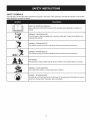 7
7
-
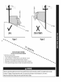 8
8
-
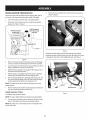 9
9
-
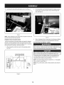 10
10
-
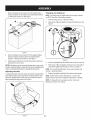 11
11
-
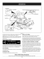 12
12
-
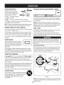 13
13
-
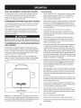 14
14
-
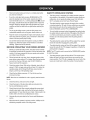 15
15
-
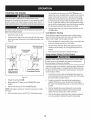 16
16
-
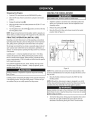 17
17
-
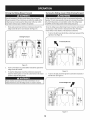 18
18
-
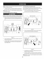 19
19
-
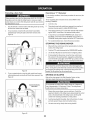 20
20
-
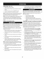 21
21
-
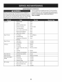 22
22
-
 23
23
-
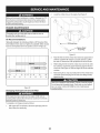 24
24
-
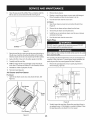 25
25
-
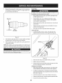 26
26
-
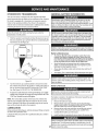 27
27
-
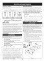 28
28
-
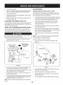 29
29
-
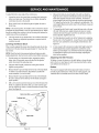 30
30
-
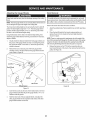 31
31
-
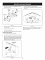 32
32
-
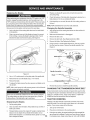 33
33
-
 34
34
-
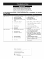 35
35
-
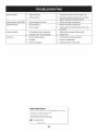 36
36
-
 37
37
-
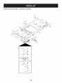 38
38
-
 39
39
-
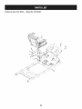 40
40
-
 41
41
-
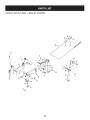 42
42
-
 43
43
-
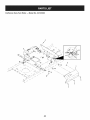 44
44
-
 45
45
-
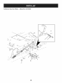 46
46
-
 47
47
-
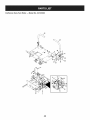 48
48
-
 49
49
-
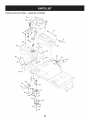 50
50
-
 51
51
-
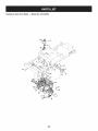 52
52
-
 53
53
-
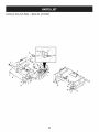 54
54
-
 55
55
-
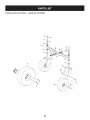 56
56
-
 57
57
-
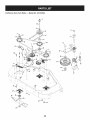 58
58
-
 59
59
-
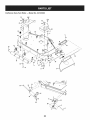 60
60
-
 61
61
-
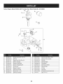 62
62
-
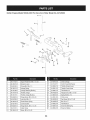 63
63
-
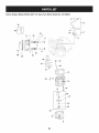 64
64
-
 65
65
-
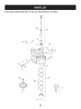 66
66
-
 67
67
-
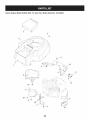 68
68
-
 69
69
-
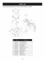 70
70
-
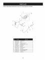 71
71
-
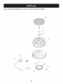 72
72
-
 73
73
-
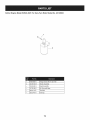 74
74
-
 75
75
-
 76
76
-
 77
77
-
 78
78
-
 79
79
-
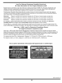 80
80
-
 81
81
-
 82
82
-
 83
83
-
 84
84
-
 85
85
-
 86
86
-
 87
87
-
 88
88
-
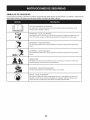 89
89
-
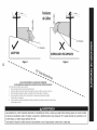 90
90
-
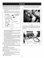 91
91
-
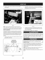 92
92
-
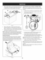 93
93
-
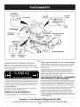 94
94
-
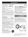 95
95
-
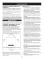 96
96
-
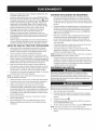 97
97
-
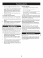 98
98
-
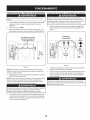 99
99
-
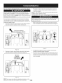 100
100
-
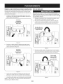 101
101
-
 102
102
-
 103
103
-
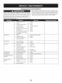 104
104
-
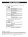 105
105
-
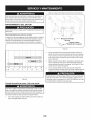 106
106
-
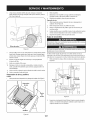 107
107
-
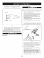 108
108
-
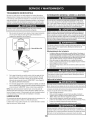 109
109
-
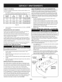 110
110
-
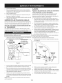 111
111
-
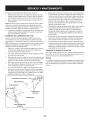 112
112
-
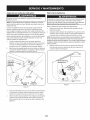 113
113
-
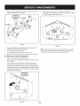 114
114
-
 115
115
-
 116
116
-
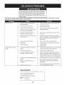 117
117
-
 118
118
-
 119
119
-
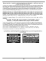 120
120
-
 121
121
-
 122
122
-
 123
123
-
 124
124


Craftsman 247250030 El manual del propietario
- Categoría
- Cortadoras de césped
- Tipo
- El manual del propietario
En otros idiomas
- English: Craftsman 247250030 Owner's manual
Documentos relacionados
-
MTD 17AK2ACP099 El manual del propietario
-
Craftsman 247.28672 Manual de usuario
-
-
-
-
-
-